

XICOY CG Meter 1.4 User Manual
1
CG & Angle Meter 1.4
Users Guide.
Plaça Pere Llauger, nau 18 08360, Canet de Mar, Barcelona, Catalonia, Spain
E-mail: sales@xicoy.com. +34 93 794 27 74
web: www.xicoy.com
Xicoy WEEE register number: ES004749 & DE 36558999
© Copyright 2015, Xicoy Electronica SL. All Rights Reserved
Manual contents & design: Gaspar Espiell. V1.4
2
Welcome!
Congratulations on the purchase of your weight, balance & angle meter. Xicoy are dedicated to
the design and production of electronic controllers to the highest standards of quality and
reliability to bring you the customer the very latest next generation designs.
Features
The Xicoy CGMeter allows both weight and balance of aero models up to 40kg (88lb) weight
(standard model) or up to 100Kg (220lb) on the HD model. By replacing the weight sensor by
angle sensors, the system can be used to adjust the travel of control surfaces and to measure
the different relevant angles in an aero plane.
The display unit can store the settings of up to 100 different models, and can save/recover the
data on a uSD card (not supplied).
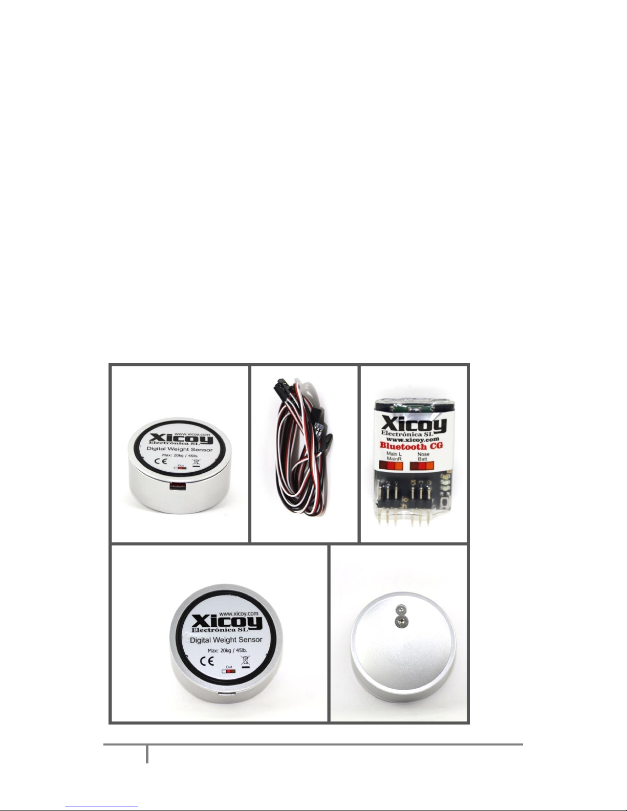
Measuring CG and Weight
The system consists of 3 x digital weight sensors, to be placed under the wheels of the
airplane, and one computer/display unit to show the results in graphical form.
Picture 1
3
Electric connections
Connect the 3 sensors to the display unit using the leads supplied
(Picture 2). Leads can be extended using standard servo leads if
necessary. Respect the proper orientation of the connector as
per the labels on the underside of the sensors and on the lateral
on the display. The 3 sensors are identical and interchangeable
on the 40kg version, but on the 100kg version, it uses 2 sensors
rated to 50Kg on the mains.
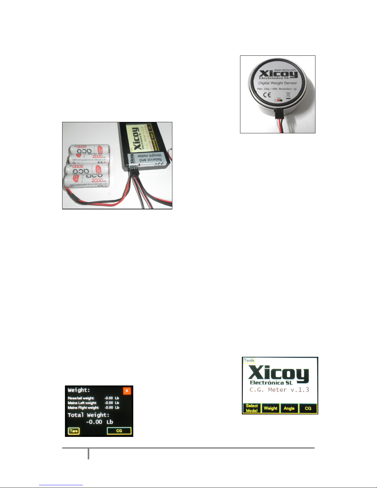
Connect a standard
battery (not supplied)
on the “Bat” input.
Battery voltage could be from 5V to 9V (Picture 3).
Connect the sensors to the sockets on the display
unit. Connect the sensor placed on the Nose
(Tricycle Undercarriage) or tail (Bicycle/Tail
Dragging planes) in the “Nose” input, and the
sensors on the main wheels on the “Left” and
“Right” inputs.
System check and calibration
Before to measure the weight or the CG, it is important to check and calibrate the sensors,
especially if they have got mechanical stress, like transport or shock, if the temperature is
significantly different since last calibration, or at least once per year.
After power-on, leave the system to stabilize for at least 5 minutes. Then touch the “weight”
button, and next touch the “Tare” button. All 3 readings should display zero. Then place a
known weight on each scale and check that the reading is accurate and same on the 3 scales. If
the readings are wrong, then perform the calibration procedure described in the “Advanced
Options” section.
Measuring the weight
Place the sensors close to the wheels of the airplane and connect
the battery. Don’t place the wheels over to the sensors yet.
Click on the “Weight” (Picture 4)
button on the main screen.
The individual readings of the 3
sensors will be displayed, together
with the Total Weight (Picture 5).
Sometimes you will see that the readings are not exactly zero. This
is normal; the sensors could drift a little due temperature and
Picture 2
Picture 3
Picture 4
Picture 5
 Loading...