

Xicom XTU-400K Operation And Installation Manual
XTU-400K
Operation and
Installation Manual
Document Number: MN5-0184-104
Revision: D
Applicable to: 305-0184-104
This is a controlled document.
The official version of this document is located
in Xicom Technology Document Control.
Printed copies are for reference only.
3550 Bassett Street
Santa Clara, CA 95054 USA
408-213-3000 Phone •408-213-3001 Fax
www.xicomtech.com

Operation and Installation Manual
XTU-400K
Document Number:
MN5-0184-104
Revision: D
Date: February 2007
XTU-400K
Operation and
Installation Manual
Document Number: MN5-0184-104
Revision: D
Applicable to: 305-0184-104
This is a controlled document.
The official version of this document is located
in Xicom Technology Document Control.
Printed copies are for reference only.
3550 Bassett Street
Santa Clara, CA 95054 USA
408-213-3000 Phone •408-213-3001 Fax
www.xicomtech.com

NOTICE
Copyright 2003 — 2007
This document contains proprietary information that is protected by copyright. All rights
are reserved.
The information in this document is subject to change without notice. Please contact
Xicom Technology for current technical specifications.
Xicom Technology reserves the right to revise this publication and to make changes
from time to time in the content hereof without obligation of Xicom Technology to notify
any person of such revision or changes.
Xicom Technology makes no war ranty of any kind with regard to this material, including,
but not limited to, the implied warranties of fitness for a particular purpose. Xicom
Technology shall not be liable for errors contained herein or for incidental consequential
damages in connection with the furnishing, performance, or use of this material.
MN5-0184-104 ii RevisionD

About this manual
XTU-400K Oper ation and Ins tallation M anual
This manual provides operators and technicians with a set of
tools for operating and maintaining the Outdoor Unit Family of
Xicom Power Amplifiers.
This Prefix contains a Table of Contents that applies to the
entire manual and a Record of Changes page that applies only
to this Prefix.
Each Chapter and Appendix has its own Part Number, Revision
Level, Record of Changes page, Table of Contents, List of
Figures, and List of Tables.
Chapter One— Provides an overview of the manual; deline ates
who should use the manual; how to contact Xicom Technology.
Chapter T wo—Describes safety information that pertains to
Xicom Technology products. It also provides information about
Warnings, Cautions and Notes that are found throughout the
manual.
Chapter Three—Provides general installation information,
communication interface switch settings and cable pinouts.
Chapter F our—Provides the operating instructions for the power
amplifier.
Chapter Five— Provides communication protocols used with
Xicom Technology power amplifiers.
Chapter Six— Describes the preventive maintenance
requirement s for Xicom Technology power amplifi ers.
Chapter Seven—Provides information regarding service and
repair of Xicom Technology power am plifiers, including
instructions on obtaining RMA (Retur n Maintenance
Authorization) Numbers.
List of Abbreviations, Acronyms, and CE Symbols— Lists the
abbreviations, acronyms, and CE symbols that may be found in
Xicom Technology documentation.
Appendices—The Appendices provide operators and
technicians with information and specifications that are specific
to their particular version of Xicom Technology Power Amplifier.
MN5-0184-104 iii RevisionD

Who should use this manual
This manual is designed for use by trained operators and
technicians who have a thorough knowledge of satellite
transmitting and receiving equipment.
Persons using this manual should familiarize themselves with
the information in the Appendices before reading the main
sections.
XTU-400K Oper ation and Ins tallation M anual
MN5-0184-104 iv RevisionD
XTU-400K Oper ation and Ins tallation M anual
Record of Changes
ELECTRONIC APPROVAL. SEE PLM.
Revision ECO Description Date Initiated By
A 9849 Original Release 05/29/2002 ALCjr
B 10125 Replace MNC-0500-013 with
08/07/2002 ALCjr
MNC-0000-015
C 11383 Update Interconnect Drawings 08/15/2003 ALCjr
D 14886 Update Table of Contents 02/20/2007 JN
MN5-0184-104 v RevisionD

XTU-400K Oper ation and Ins tallation M anual
Table of Contents
Paragraph Title Page Number
List of Abbreviations, Acronyms, and CE Symbols MNC-0000-010
Chapter 1 Overview MNC-0100-003
Chapter 2 Safety MNC-0200-001
Chapter 3 Unpacking and Installation MNC-0300-003
Chapter 4 Operation MNC-0400-001
Chapter 5 Amplifier Communication and Protocol MNC-0500-002
Chapter 6 Preventive Maintenance MNC-0600-003
Chapter 7 Service and Repair MNC-0700-001
Appendix A Product Specifications 305-0184-104
Appendix B Mechanical Drawings
Outline 304-0092-001
Appendix C Interconnect Drawings
RF Unit Interconnect 307-0162-104
Logic Interconnect 307-0165-104
Power Supply Unit Interconnect 307-0581-002
High Voltage Unit I nterconnect 307-0582-001
Appendix D Operation Addendum, Block Upconverter MNC-0000-015
MN5-0184-104 vi Revision D
List of Abbreviations, Acronyms , a nd CE Sy mbols
List of Abbreviations, Acronyms, and CE Symbols
Record of Changes
ELECTRON IC AP PR OVAL . SE E P LM.
Revision ECO Description Date Initiated By
A 9735 Original Release 04/17/2002 A.L. Crozier, Jr.
A1 10179 Add numerous abbreviations 08/21/2002 A.L. Crozier, Jr.
A2 10646 Add more abbreviations; CE symbols 01/14/2003 A.L. Crozier, Jr.
A3 11044 Add more abbreviations 05/15/2003‘A.L. Crozier, Jr.
A4 11802 Add more abbreviations 01/13/2004 A.L. Crozier, Jr.
A5 12050 Add more abbreviations 03/19/2004 A.L. Crozier, Jr.
A6 12808 Add more abbreviations 02/23/2005 A.L. Crozier, Jr.
A7 14758 Correct entries and add n ew entries 09/08/2006 ALCJr
MNC-0000-010 1 of 10 Revi sion A7

MNC-0000-010 2 of 10 Revi sion A7
List of Abbreviations, Acronyms , a nd CE Sy mbols
List of Abbreviations, Acronyms, and CE Symbols
References
The following documents are used as reference material for this
chapter:
• International Standard ISO-7000: 1989. Graphical symbols for use on
equipment — Index and synopsis
• International Standard CEI/IEC 60417-2: 1998. Graphical symbols for
use on equipment — Part 2: Symbol originals
• Society of Exploration Geophysicist. 1980. The SI Metric System of
Units And SEG Tentative Standard.
• The American Society of Mechanical Engineers. November 1999.
ASME Y14.38-1999. Abbreviations and Acronyms.
• Wachal, Robert S. 1999. Abbreviations Dictionary: A practical
compilation of today’s acronyms and abbreviations. Boston/New York:
Hougton Mifflin Company.
• Franklin Covey. 1999. Franklin Covey Style Guide: FOR BUSINESS AND
TECHNICAL COMMUNICATION,THIRD EDITION.
Abbreviations and Acronyms
Abbreviation or
Acronym
AC alternating current
ack Acknowledgement
ad analog-to-digital
ADC analog-to-digital converter
AFC automatic frequency control
AGC automatic gain control
ALC automatic level control
amp (A) ampere
amphr ampere-hour
ampl amplifier
anlg analog
ant antenna
ATP Acceptance Test Procedure
AVC automatic volume control
BA buffer amplifier
Definition
MNC-0000-010 3 of 10 Revi sion A7

List of Abbreviations, Acronyms , a nd CE Sy mbols
Abbreviation or
Acronym
Definition
BDELIM band elimination
BIT binary digit
bmw beamwidth
btry battery
BUC Block Upconverter
buz buzzer
bw bandwidth
°C degree Celsius
cal calibration
CATE comp uter aided test equipmen t
CB component board
CCTWT Coupled Cavity Traveling Wave Tube
commsat communications satellite
CPU central processing unit
CRC Cyclic Redundancy Check
CTRF center frequency
CTS Clear to Send
CW continuous wave
DA digital-to-analog
DAC digital-to-analog converter
dB Decibel
dBc Decibels referenced to carrier
dBI
Decibels referenced to Amperes or Decibels referenced to
Isotropic Gain
dBm decibels referenced to one milliwatt
dBW decibels referenced to Watts
DC direct current
DCD Date Carrier Detect
deg degree
dgtl digital
distn distortion
DSR Data Send Ready
DTR Data Terminal Ready
Ef filament voltage
EIK Extended Interaction Klystron
Ek cathode voltage
EMI electromagnetic interference
ETX End of Transmission
MNC-0000-010 4 of 10 Revi sion A7

List of Abbreviations, Acronyms , a nd CE Sy mbols
Abbreviation or
Acronym
Definition
Ew helix voltage
°F degree Fahrenheit
F farad
FAT First Article Test
FET field-effect transistor
FGIPA Fixed Gain Intermediate Power Amplifier
freq frequency
FTD Filament Time Delay (TWTA, KPA)
G Giga (one billion)
GHz Giga Hertz
H henry
Hi-pot
Process using a high voltage p ower supply to verify h igh voltage
insulation leakage.
HPA High Power Amplifier
HV High Voltage
Hz Hertz
IC integrated circuit
IESS Intelsat Earth Stati on Standards
IF Intermediate Frequency
I/P Input
inv inverter
IPA Intermediate Power Amplifier
IrDA Infrared Data Association
Iw helix current
k kilo (one thousand)
K cathode
kg kilogram
kHz kilo Hertz
KMT Klystron Microwave Tube
KPA Klystron Power Amplifier
kV kilo Volt
kVAH kilovolt-ampere hour
kVAHM kilovolt-ampere hour meter
kVAM kilovolt-ampere meter
kW kilo Watt
kWHM kilowatt-hour meter
LC inductance-capacitance
LCD liquid crystal display
MNC-0000-010 5 of 10 Revi sion A7

List of Abbreviations, Acronyms , a nd CE Sy mbols
Abbreviation or
Acronym
Definition
LDA Line Driver Amplifier
LED Light Emitting Diode
LO Local Oscillator
LPA Low Power Amplifier
M Mega (million)
M&C Monitor and Control
mA milli Ampere
MSDC Multistage Depressed Collector
MHz Mega Hertz
miprcs microprocessor
MPS Modular Power Supply
MSDC Multi-Stage Depressed Collector
MSL mean sea level
MTBF mean time between failures
MTTR mean time to repair
mV milli Volt
MW Mega Watt
mW milli Watt
NAK negative acknowledgement
oc overcurrent
ODU Outdoor Unit
OEM other equipment manufacturer
O/P Output
ovv over voltage
PBIT parity bit
PCB printed circuit board
PF power factor
PFC power factor correction
PS power supply
PSU power supply unit
PWM pulse-width modulation
pwr Power
RF Radio Frequency
RFU RF Unit
RMA Returned Material Authorization
RMS root mean square (.707)
RTS Ready to Send
MNC-0000-010 6 of 10 Revi sion A7

List of Abbreviations, Acronyms , a nd CE Sy mbols
Abbreviation or
Acronym
Definition
In a standard 19-inch rack, a set of fo ur mounting holes sp aced
as follows:
RU
.625 inches between holes 1, 2, and 3.
.5 inches between holes three and four.
RU = 1.75 inches.
RXD Received Data
SLIN Linearizer with an integrated variable gain SSA
SSA Solid State Amplifier
SSPA Solid State Power Amplifier
STDBY Standby
STX Start of Transmission
TD Time Delay (SSPA)
TEC
Thermal Electric Cooling. This is a technique used to regulate
the operating te mperature environment of a device.
TPS Test Performance Sheet
TWT Traveling Wave Tube
TWTA Traveling Wave Tube Amplifier
TXD Transmitted Data
UMBC umbilical cord
undc undercurrent
UPS uninterrupible power supply
VAC Volts alternating current
VDC Volts direct current
VGA variable gain amplifier
VGIPA Variable Gain Intermediate Power Amplifier
VPC Variable Phase Combiner
VSWR voltage standing wav e ratio
W Watt
wg waveguide
Wh watthour
WHM watthour meter
wm watt meter
wtrg with respect to ground
wtrc with respect to cathode
wtrprf waterproof
wtrtt watertight
WV working voltage
XFMR Transformer
MNC-0000-010 7 of 10 Revi sion A7
List of Abbreviations, Acronyms , a nd CE Sy mbols
Abbreviation or
Acronym
Definition
XMIT Transmit
XT Xicom Technology Analog Outdoor Amplifier
XTC Xicom Technology Controller
XTD Xicom Technology Digital Outdoor Amplifier
XTK Xicom Technology Klystron Ampli fier
XTKD Xicom Technology Klystron Amplifier with Flat Display
XTKH
Xicom Technology Klystron High Efficiency Amplifier — Flat
Display with Multistage Depressed Collector
XTPS Xicom Technology Power Supply
XTRD Xicom Technology Rack Mount Digital Amplifier
XTRD-LDA Xicom Technology Rack Mount Line Driver Amplifier
XTRS Xicom Technology Solid State Rack Mount Amplifier
XTS Xicom Technology Solid State Outdoor Amplifier
XTU Xicom Technology Outdoor Amplifier with Block Upconverter
MNC-0000-010 8 of 10 Revi sion A7
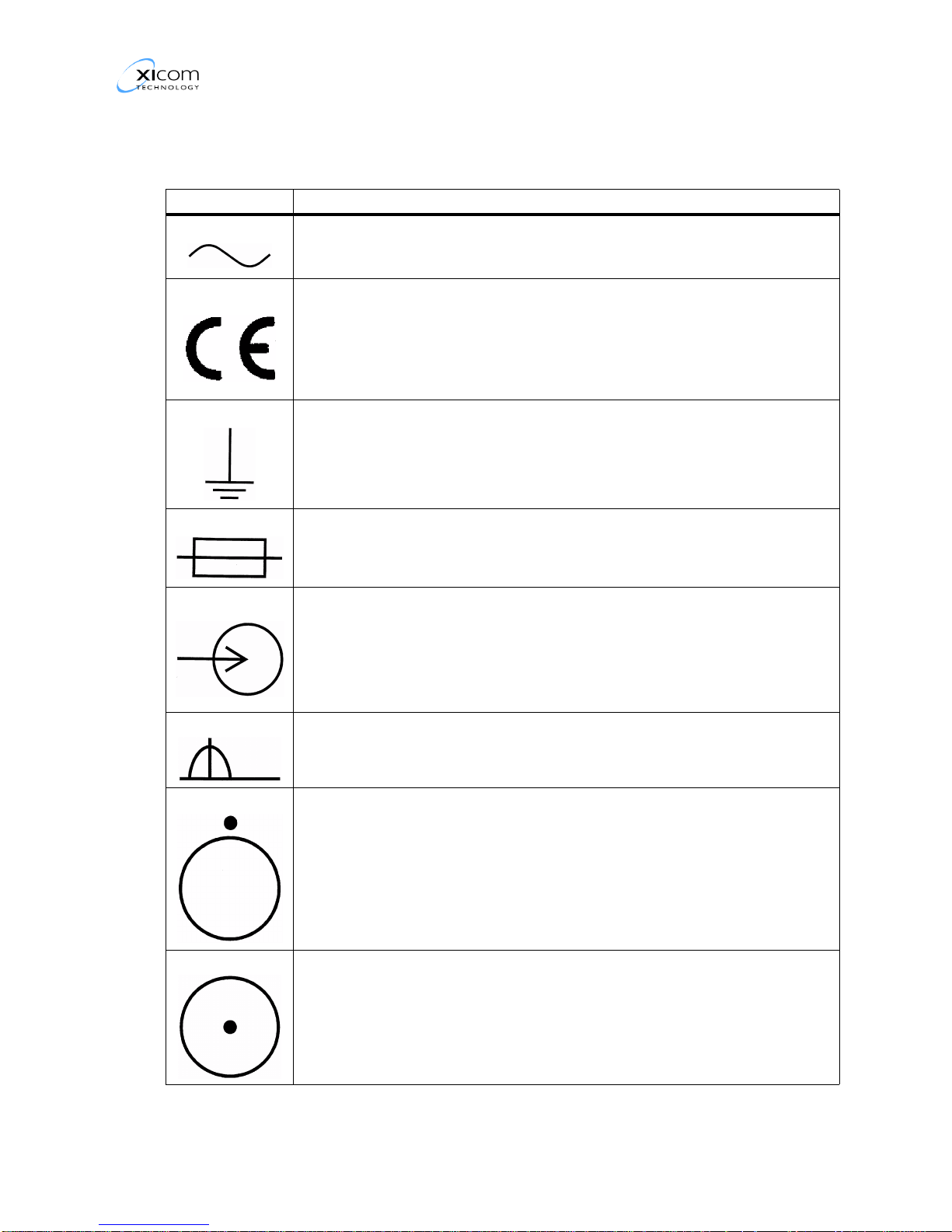
CE Symbols
Symbol Definition
List of Abbreviations, Acronyms , a nd CE Sy mbols
Alternating Current (AC)
CE Marking symbol for equipment and documentation meeting
European Quality Standards.
Earth Ground
Fuse
Input
Local
OFF for a part of equipment
ON for a part of equipment
MNC-0000-010 9 of 10 Revi sion A7
List of Abbreviations, Acronyms , a nd CE Sy mbols
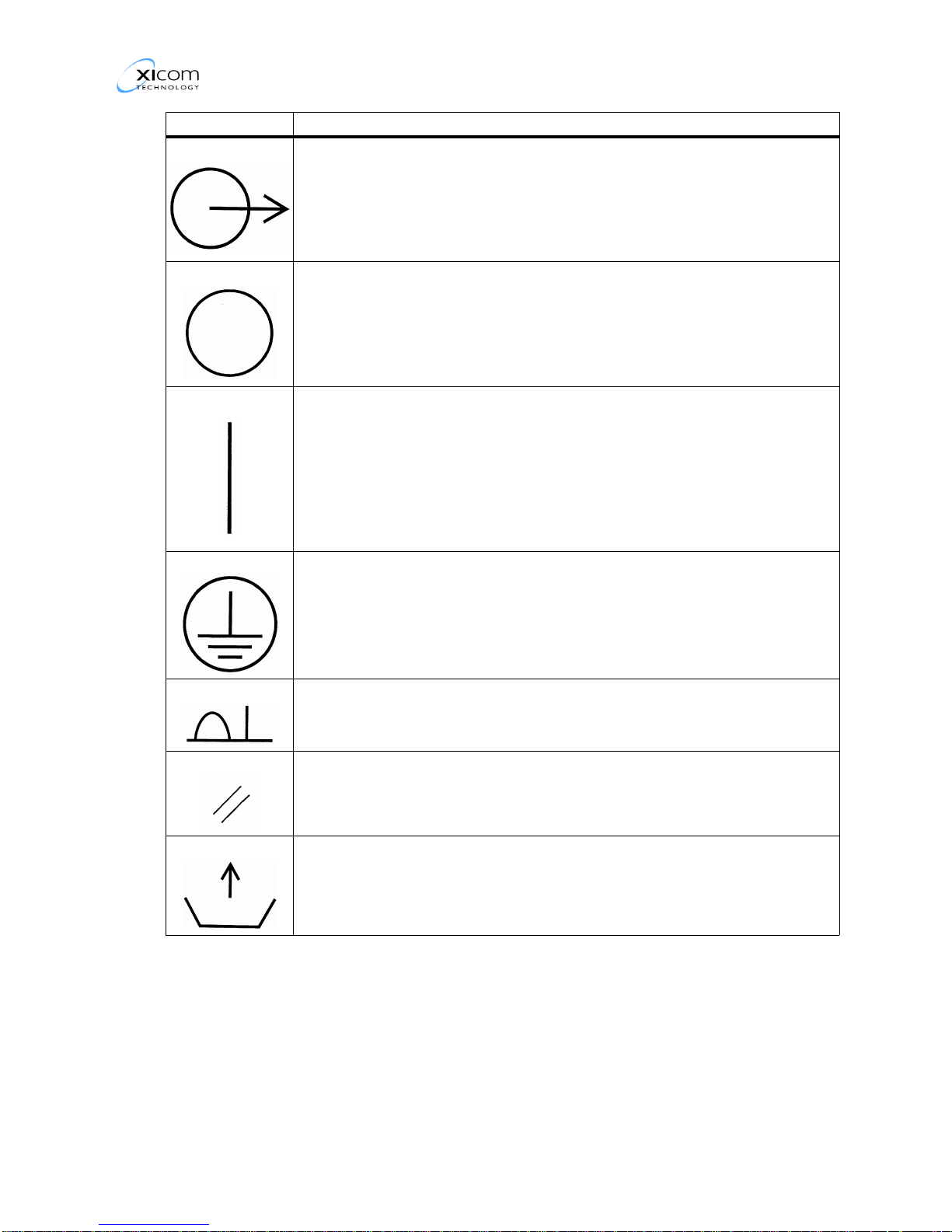
Symbol Definition
Output
Power OFF
Power ON
Protective Earth Ground
Remote
Reset
Transmitted Power Monitor
MNC-0000-010 10 of 10 Revi sion A7
Overview, Digital ODU HPAs
Overview, Digital ODU HPAs
Record of Changes
Revision ECO Description Date Initiated By
A 9295 Original Release 11/29/2001 A.L. Crozier, Jr.
B 10359 Update Contacting Xicom Technology
paragraph
C 11301 Update to reflect Waveguide Switching 08/08/2003 A.L. Crozier, Jr.
10/14/2002 A.L. Crozier, Jr.
MNC-0100-003 1 Revision C

Overview, Digital ODU HPAs
Table of Contents
Paragraph Title Page Number
Overview . . . . . . . . . . . . . . . . . . . . . . . . . . . . . . . . . . . . . . . . . . . . . . . . . . . . . . . . . . . . 3
Product Overview . . . . . . . . . . . . . . . . . . . . . . . . . . . . . . . . . . . . . . . . . . . . . . . . . . . 3
Control and Status Interface . . . . . . . . . . . . . . . . . . . . . . . . . . . . . . . . . . . . . . . . 3
Physical Characteristics . . . . . . . . . . . . . . . . . . . . . . . . . . . . . . . . . . . . . . . . . . . . . . 5
Environmental Characteristics . . . . . . . . . . . . . . . . . . . . . . . . . . . . . . . . . . . . . . . . . 5
Specifications . . . . . . . . . . . . . . . . . . . . . . . . . . . . . . . . . . . . . . . . . . . . . . . . . . . . . . 5
Contacting Xicom Technology . . . . . . . . . . . . . . . . . . . . . . . . . . . . . . . . . . . . . . . . . 6
Assistance. . . . . . . . . . . . . . . . . . . . . . . . . . . . . . . . . . . . . . . . . . . . . . . . . . . . . . 6
Feedback . . . . . . . . . . . . . . . . . . . . . . . . . . . . . . . . . . . . . . . . . . . . . . . . . . . . . . 6
List of Figures
Number Title Page Number
Figure 1, Typical ODU Antenna Mount Amplifier Block Diagram. . . . . . . . . . . . . . . . . . 4
List of Tables
Number Title Page Number
Table 1, Environmental Specifications. . . . . . . . . . . . . . . . . . . . . . . . . . . . . . . . . . . . . . 5
MNC-0100-003 2 Revision C

Overview, Digital ODU HPAs
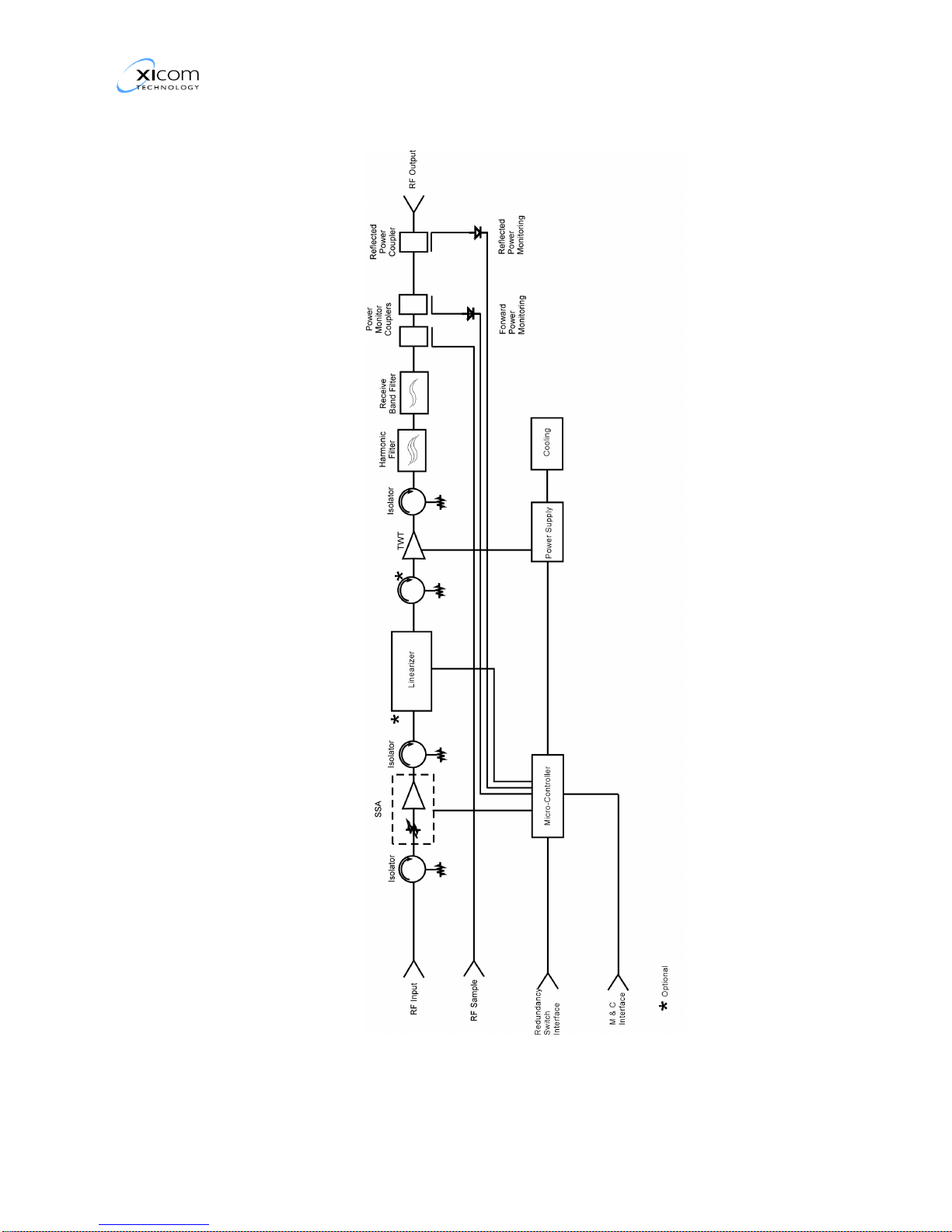
Product Overview
This manual is for the Xicom Technology ODU (Outdoor Unit)
Power Amplifier with microprocessor control. The ODU may be
mounted on an antenna or other outdoor location without the need
for an additional watertight enclosure. The standard amplifier
consists of:
• a Microwave Tube.
• an SSA (Solid State Amplifier).
• a power monitor.
• a Power Supply.
• a Linearizer (optional).
• an M&C (Monitor & Control) system.
• serial control interfaces (COM1 and COM2).
Overview, Digital ODU HPAs
• a forced air cooling system.
• 1:1 Waveguide switching capability.
The COM1 interface is RS-232 only; the COM2 interface is
configured for RS-422/RS-485 operation. There are hardwired
summary fault and external interlock circuits available for user
defined functions.
Refer to Figure 1, on page 4 for a typical block diagram of the
Power Amplifier.
Refer to Appendix titled Specifications for the details of your
amplifier.
Control and Status Interface
The amplifier is controlled in Local Mode from the switches on the
unit or in Remote Mode from an external controller or M&C system.
Refer to the Operation and Communication and Protocol Chapters
to operate the power amplifier in the Remote Mode.
MNC-0100-003 3 Revision C
Overview, Digital ODU HPAs
MNC-0100-003 4 Revision C
Figure 1, Typical ODU Antenna Mount Amplifier Block Diagram
Physical Characteristics
Refer to Appendix titled Mechanical Drawings for the Physical
Characteristic Specifications of your amplifier.
The Xicom ODUs are air cooled where the outside cooling air does
not pass through the microwave tube and power supply enclosure.
The tube and power supply are conduction cooled. They are
mounted on a thick, finned aluminum plate. A fan pushes outside
air through the fins keeping moist cooling air separate from the tube
and power supply.
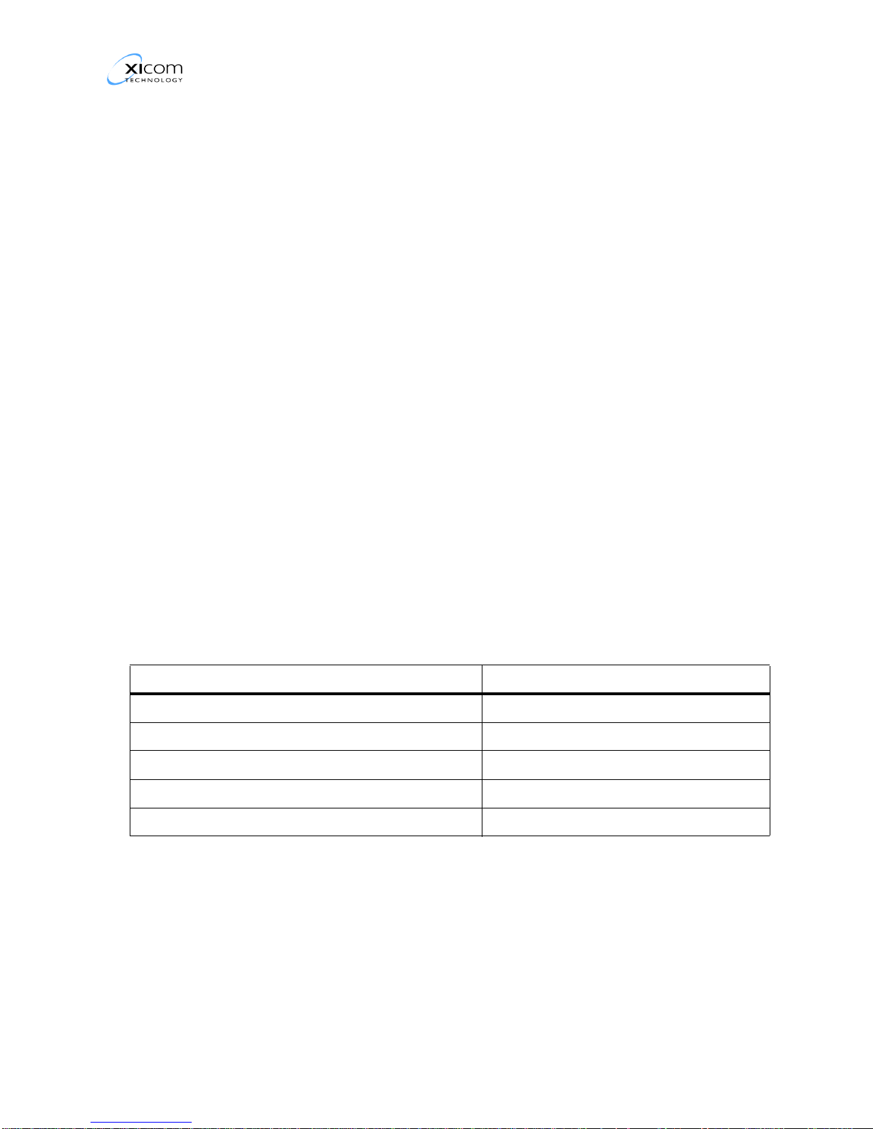
Environmental Characteristics
Table 1, Environmental Specifications, lists the typical amplifier
environmental specifications.
Refer to the appendix titled Specifications for the environmental
specifications unique to your amplifier.
Overview, Digital ODU HPAs
The amplifier is designed to operate in rain and snow. However, in
high snow load conditions it is advisable to provide a snow shroud
to prevent a buildup of snow at the air inlet causing a blockage that
will reduce air flow.
Table 1, Environmental Specifications
Parameter Specification
NON-OPERATING TEMPERATURE RANGE -50°C to +70°C
OPERATING TEMPERATURE RANGE -40°C to +50°C
ALTITUDE 10,000 feet MSL maximum
SHOCK AND VIBRATION Normal transportation
COOLING Forced air
Specifications
Refer to the Appendix titled Specifications for the specifications of
your amplifier.
MNC-0100-003 5 Revision C

Contacting Xicom Technology
Assistance
If you need to contact Xicom Technology for assistance with your
product you may use one of the following:
Address:
Xicom Technology
3550 Bassett Street
Santa Clara, CA 95054 USA
Telephone: 408-213-3000
Facsimile: 408-213-3001
www.xicomtech.com
Overview, Digital ODU HPAs
Feedback
Technical Support —
email: support@xicomtech.com
Telephone: 408-213-3109 (24 Hours)
Facsimile: 408-213-3107
Sales: sales@xicomtech.com
Xicom technology wants to receive customer feedback concerning
the format, content and accuracy of the documentation that is
shipped with the products. We also want customers to submit
comments and suggestions or request assistance in solving
problems with any of our products.
Please access our web site at http://www.xicomtech.com
and click
on Customer Feedback Forms to go to the Customer Feedback
Page. You may download the appropriate form and submit your
requests and comments using the forms on this page.
MNC-0100-003 6 Revision C
Safety/Sicherheit
Safety/Sicherheit
Record of Changes
Revision ECO Description Date Initiated By
1 Preliminary Release 08/2001 A.L. Crozier, Jr.
2 Format changes 08/2001 A.L. Crozier, Jr.
3 Format change—Table of Contents, List
of Figures, List of tables
A 9183 Original Release 10/12/2001 A.L. Crozier, Jr.
B 9288 Update to include 2kW Amplifiers 11/20/2001 A.L. Crozier, Jr.
C 9433 Change “dispatching” to “dissipating” on
page 7.
D 9535 Add General W arning on page 4. 02/22/2002 A.L. Crozier, Jr.
E 12926 Add German Translation for CE
compliance
09/2001 A.L. Crozier, Jr.
01/24/2002 A.L. Crozier, Jr.
03/22/2005 A.L. Crozier, Jr.
MNC-0200-001 1 of 14 Revision E

Safety/Sicherheit
Table of Contents
Paragraph Title Page Number
Safety/Sicherheit. . . . . . . . . . . . . . . . . . . . . . . . . . . . . . . . . . . . . . . . . . . . . . . . . . . . . . . . . . . . . . . 3
General Information . . . . . . . . . . . . . . . . . . . . . . . . . . . . . . . . . . . . . . . . . . . . . . . . . . . . . . . . . . 3
Summaries . . . . . . . . . . . . . . . . . . . . . . . . . . . . . . . . . . . . . . . . . . . . . . . . . . . . . . . . . . . . . . . . . 3
Description . . . . . . . . . . . . . . . . . . . . . . . . . . . . . . . . . . . . . . . . . . . . . . . . . . . . . . . . . . . . . . 3
Warnings, Cautions, and Notes . . . . . . . . . . . . . . . . . . . . . . . . . . . . . . . . . . . . . . . . . . . . . 3
General Warnings and Cautions. . . . . . . . . . . . . . . . . . . . . . . . . . . . . . . . . . . . . . . . . . . . . . . . 5
High Volt age Hazards . . . . . . . . . . . . . . . . . . . . . . . . . . . . . . . . . . . . . . . . . . . . . . . . . . . . . 5
Ladder Hazards . . . . . . . . . . . . . . . . . . . . . . . . . . . . . . . . . . . . . . . . . . . . . . . . . . . . . . . . . . 6
RF Radiation Hazards . . . . . . . . . . . . . . . . . . . . . . . . . . . . . . . . . . . . . . . . . . . . . . . . . . . . . 7
Magnetic Field . . . . . . . . . . . . . . . . . . . . . . . . . . . . . . . . . . . . . . . . . . . . . . . . . . . . . . . . . . . 7
Sicherheit . . . . . . . . . . . . . . . . . . . . . . . . . . . . . . . . . . . . . . . . . . . . . . . . . . . . . . . . . . . . . . . . . . 8
Allgemeine Information . . . . . . . . . . . . . . . . . . . . . . . . . . . . . . . . . . . . . . . . . . . . . . . . . . . . 8
Zusammenfassungen . . . . . . . . . . . . . . . . . . . . . . . . . . . . . . . . . . . . . . . . . . . . . . . . . . . . . 8
Beschreibung . . . . . . . . . . . . . . . . . . . . . . . . . . . . . . . . . . . . . . . . . . . . . . . . . . . . . . . . . 8
Warnungen, V o rsichtshinweise und Hinweise . . . . . . . . . . . . . . . . . . . . . . . . . . . . . . 8
Allgemeine Warnungen und V orsicht shinweise . . . . . . . . . . . . . . . . . . . . . . . . . . . . . . . 10
Hochspannungsgefahren . . . . . . . . . . . . . . . . . . . . . . . . . . . . . . . . . . . . . . . . . . . . . . 10
Gefahren bei Leiterbenutzung . . . . . . . . . . . . . . . . . . . . . . . . . . . . . . . . . . . . . . . . . . 12
Gefahren durch Hochfrequenzstrahlung . . . . . . . . . . . . . . . . . . . . . . . . . . . . . . . . . . 12
Magnetfeld . . . . . . . . . . . . . . . . . . . . . . . . . . . . . . . . . . . . . . . . . . . . . . . . . . . . . . . . . . 13
MNC-0200-001 2 of 14 Revision E

Safety/Sicherheit
General Information
This chapter identifies the safety requirements to be applied when
performing any of the procedures specified in this manual. It is the
responsibility of the user to follow all applicable safety regulations
when using this manual. This chapter contains safety summaries
consisting of general safety and health precautions.
Summaries
Description
Equipment of this nature has inherent hazards. Only trained
Operators and Service Personnel should work on or operate this
equipment.
The general safety requirements identified in this chapter are
applicable to anyone doing the procedures included in this manual.
Safety/Sicherheit
Warnings, Cautions, and Notes
Warnings, cautions, and notes are used in these procedures to alert
the user to special conditions regarding safety or correct performance
of a particular step or steps. They are placed immediately prior to the
procedural step to which they apply , or immediately prior to the
procedure itself if they apply to the entire procedure.
Warnings and cautions are constructed in three part s or sentences.
First, the hazard is stated; second, the correct action to be performed
is stated; and, third, the result of failing to comply with the action is
stated. Notes, however , can be in any form necessary to convey the
needed information. The definitions below show how warnings,
cautions, and notes are used.
MNC-0200-001 3 of 14 Revision E
Safety/Sicherheit
W ARNING — A procedure, technique, restriction, etc., if not followed
exactly , could result in injury or death to personnel.
W ARNING
This symbol denotes an ELECTRICAL SHOCK HAZARD WARNING
in a procedural step and is used whenever death or injury to personnel
could result from electrical shock.
W ARNING
This symbol denotes a RADIO FREQUENCY BURN HAZARD
WARNING in a procedural step and is used whenever death or injury
to personnel could result from radio frequency burns.
W ARNING
This symbol denotes a LADDER F ALL HAZARD W ARNING in a
procedure step and is used whenever death or injury to personnel
could result from improper use of a ladder .
W ARNING
This symbol denotes a GENERAL HAZARD WARNING in a
procedural step and is used whenever death or injury to personnel
could result from improper performance of the procedural step.
Caution — A procedure, technique, restriction, etc., if not followed
exactly , could result in damage to equipment.
Caution
This symbol denotes a CAUTION in a procedural step. A CAUTION is
used whenever equipment damage could result if the procedure is not
correctly followed.
MNC-0200-001 4 of 14 Revision E
Note — A procedure, technique, restriction, special interest, etc., that
requires emphasis or consideration for the performance of a
procedural step or steps.
This symbol denotes a NOTE in a procedural step. A NOTE is used
whenever emphasis or consideration for the performance of a
procedural step or steps is necessary .
General Warnings and Cautions
High V olt age Hazards
Safety/Sicherheit
Note
W ARNING
The ODU (Outdoor Unit) power amplifier is not equipped with internal
safety interlock switches. Turn OFF primary power before removing
amplifier enclosure cover . Failure to comply could result in serious
injury or death.
W ARNING
The power amplifier uses high voltage that may be lethal if contacted.
When the amplifier’s power supply cover is removed multiple high
voltage points are exposed. Use extreme care when operating the
amplifier with the cover removed. Failure to comply could result in
serious injury or death.
W ARNING
To prevent electrical shock the amplifier should not be operated with
the cover removed unless service personnel are thoroughly familiar
with its operation and are experienced with high voltage. Failure to
comply could result in serious injury or death.
W ARNING
To prevent electrical shock use a shorting probe rated at 20 kV
isolation at the handle to discharge capacitors. Failure to comply could
result in serious injury or death.
MNC-0200-001 5 of 14 Revision E
Safety/Sicherheit
W ARNING
To prevent electrical shock when servicing a Klystron Tube or a 2 kW
Power Amplifier:
• ensure the Bus Indicator LED located in the Power Supply Drawer
High Vo ltage side is out.
• use shorting probe before taking measurements on the capacitor
bank.
Failure to comply could result in serious injury or death.
W ARNING
When required to measure voltages in a High V oltage Power Supply:
• turn the equipment OFF.
• use shorting probe to ensure capacitors are discharged.
• ensure meter probes are properly insulated and capable of handling
votlages of 20 kV or more.
• attach probes using one hand.
• ensure probes are not touching other contacts.
Failure to comply could result in serious injury or death.
Ladder Hazards
W ARNING
When required to use a ladder ensure that:
• the ground in the area where the ladder will be used is free of
objects that could cause the ladder to be unstable.
• Y ou have read and understand ALL the labels that are af fixed to the
ladder .
• you are wearing all appropriate safety equipment such as hard hat,
safety harness, etc.
Failure to comply could result in serious injury or death.
MNC-0200-001 6 of 14 Revision E
 Loading...