

Hea rt to per fecti on、Born f or make r
Robots Instructions
www.throbots.cn
Wifi-robots Edu Platform
WiFi-Robots Edu Platform -C
Heart to perfection、Born for maker
shenz hen Chi na

Solemnly declare
Catalog
Solemnly declare:
1.The technic al data and the c opyrigh t of system software which are
provided by this produc t one and onl y belongs to th e developer,and th e
use is prote cted by the cop yright law of the People's Re public of China.
Without the written permissi on, any uni t or individual shall not sell ,
rental, copy, modify, or dis close the tec hnical data and softwa re c ontent
to third par ties, a nd your side wi ll beheld res ponsible for all the con sequences for its all p ro per ty proper ty disp utes which crea tived by the
techni cal data or sof twarevers ion .
2.This product is s uitable f or 12 years of age an d older use rs, and
enthusiasts and e ducatio n or teaching a ims, shall not suitabl e for
industrial, con sumer, militar y a nd other fi elds.
3.Please use the ba ttery and elec tronic acce ssories as our company
standard. If the user s change to the other acce ssories , all mista kes or
damages of rob ot can not enjoy the warra nty.
4.The company reser v es the right to c hange witho ut prior no tice of
this products descr ibed in thi s manual. For printing e rrors and program
changes ,the compan y can make the nece ssary chan ges at any time to
the new manual.
5.The company reser v es the rights of software upgrade and interests
of the final f unction a t the actual situation i n the machi ne,and the
company has the final e xplanat ion right.
6. I have carefully read an d noted the bes t statement of th e content.
Ⅰ. The list of items
Ⅱ. Matters needi ng attention
Common prob lems an d troub lesho oting s oluti on
Ⅲ.
... .. ... .. ... .. ... .. ... .. ... .. ... .. ... .. ... .. ... .. ... .. ... .. ... .. ... .. ... .. ... .. ... .. ..
... .. ... .. ... .. ... .. ... .. ... .. ... .. ... .. ... .. ... .. ... .. ... .. ... .
Ⅳ. The instruction of main control board
1.51duino Mainb oa rd
2. Arduino PWR Power-Motor dri ver board
Ⅴ.
Assembly drawings
5.1.
5.2.
Integr al wiring d iagram of elect ro nic system
1. 51duino
2. Arduino/STMdui no
Hardware installati on
5.2. 1.
Hardware installati on
5.2. 2. installation
Robot Link WiF i
5.2. 3.
Assembly drawin gs for Came ra and Cradle
5.2. 4.
Motors assembly
..... .. ..... .. ... .. ..... .. ..... .. ..... .. ... .. ..... .. ..... .. ..... ..... .. ..... .. ..... .
... .. ... .. ... .. ... .. ... .. ... .. ..
..... .. ..... .. ... .. ..... .. ..... .. ..... .. ... .. ..... .. ..... .. ...
... .. ... .. ... .. ... .. ... .. ... .. ... .. ... .. ... .
... .. ... .. ... .. ... .. ... .. ... .. ... .. ... .. ... .. ... .. ... .. ... .. ... ..
5.3. Assemb ly drawings over view for DS Robot
Ⅵ.
Extras functions of Sensors and mode switch
6.1. Sensor insta llation f or full function mode
... .. ... .. ... .. ... .. ... .. ... .. ... .. ... .. ... .. ... .. ... .. ... .. ... .. ... .. ... .. .
sensors
... .. ... .. ... .. ... .. ... .. ... .. ... .. ... .. ... .. ... .. ..
... .. ... .. ... .. ... .. ... .. ... .. ... .. ... .. ... .. ... .. ... .. ... .. ... .. .
6.2.
1.
51duino sensors
2. Arduino/STMdui no
The tuto rial of switching m ode in the software
Download Android APP
Ⅶ. Using the tutorial
1.Opera tion in struc tions o f the product(PC)
2. HONE/PADOperation instru ction s of the pr oduct (P )
... .. ... .
... .. ... .. ...
... .. ... .. ... .. ... .. ... .
... .. ... .. ... .. .
... .. ... .. ... .. ... .. ... .. .
... .
01
02
03-0 4
05
06
07
08
07-0 8
09
10-1 4
15-1 6
17-1 8
19
20
21
22
23-2 4
25-2 6

Ⅰ. The list of items
1. DS R ob ot
①.PCB m at er ial chassis*1
②.Mai n co nt rol board *1
③.Reg ul at ed power supply a nd m ot or driver board (P WR b oard)*1
(no this t yp e in 5 1duino )
④.Robot-Link W iFi video d ata module*1
⑤.Robot-Eye s USB camera*1
⑥.Te batter y and t he charger* 1
⑦.The wheels and motor*4
⑧.SG90 ser vo *2
⑨.The nylon parts of c radle*1
⑩.USB2.0 to MicroUSB cab le *1
⑪.Hardw are in bag*1
⑫.Wire *1
2.TH Robot
①.Cra wl er c hassis*1
②.Mai n co nt rol board *1
③.
Regu la te d power supply an d mo to r driver board( PW R bo ard)*1
(no this t yp e in 5 1duino )
④.Robot-Link W iFi video d ata module*1
⑤.Robot-Eye s USB camera*1
⑥.Te batter y and t he charger* 1
⑦.SG90 ser vo*2
⑧.The nylon parts of *1
⑨.USB2.0 to MicroUSB cable *1
⑩.Hardware in bag*1
⑪.Wire*1
⑫.Four degrees of freedom manipulator
(The ver sion with m anipula tor)
⑬.Driver board of manipula tor(The ver sion with m anipula to r)
⑭.Extension card of motor* 3(The ver sion with m anipulato r)
⑮.Infrared senso r*2(The ver sion with line patrol)
infrared sensor*3
(The version with line patrol&obs tacle avoid ance & foll owing)
⑯.Uit rasonic s ensors* 1(The ver sion with obstacle avo idance)
⑰.Miu nting base of sensor(The ver sion with s ensor)
Note (E ach pro duct pa ckage s are not t he s ame,t he real o bj ect sho ul d
be cons idere d as f inal ac tual pu rchas e of good s )
cradle
Ⅱ. Matters needing attention
1. please do not inst all the battery in t he mother b oa rd at first step. I t
will easily burne d circuit bec ause of short circuit wh ile insta lling,
please install th e other ele ctrical e quipment, and then put t he
batter y into th e main cont ro l board.
2. Before power on, ple ase carefully check the wi ring is cor re ct, if there
are other metal objec ts on the circu it board, eliminate all shor t
circuit condition s before you can turn it on.
3. The batte r y is not allowe d to inversel y connect , other wise it will
cause irreversible damage.
4. The robot only allow s one clien t software access at a time, i f you
have a cli ent softw are in the control co ndition , it needs to qui t the
current clientsof tware to access a nother ne w one.
5. 【Special attention】Before electrify t he robot with c radle or
robotic arm,the use rs should rea d specifi cation of clien t software,
then according it to adjust the angl e of each steerin g gear,finally
use the 'locking' f unction to lo ck all angl es of ser vo.
Without this step, it will lead to the servo damage cause
long time to go to the unavailable zone.
6.【Special attention】Please do not turn on th e ro bot when TX , RX
of WiFi board in sho rt ci rc uit conditions, othe r wise it wil l cause the
lights in WiFi board alwa ys shinin g, and the users can not s earch
the single. Find mo re s olve ways in
shoo ti ng s ol ution
7.【Special attention】
module, it is impor tan t to note that resistance in R68 m ark on the
WiFi module.We suggest clamp nut n ot moving ,and use the rotating
way to ins tall the column nylon on t he otherside, othe r wise the
rotary nut in t his side of is likely to lead to R68 resistance touch off
by exter nal forces.
.
Note: wh en installing nylon column to the WiFi
Comm on p ro blems and troub le
/// // /// // /// // /// // /// // /// // /// // /// // /// // /// // /// // /// // /// // /// // /// // /// // 1 / /// // /// // /// // /// ///// ///// ///// ///// ///// /// // /// // /// // /// // /// // /// /// // /// // /// // /// // /// // /// // /// // /// // /// // /// // /// // /// // /// // /// // /// // // 2 // // /// // /// // /// // /// ///// ///// ///// ///// ///// /// // /// // /// // /// // /// // /// //

Ⅲ.Common problems and trouble shooting solution
Q1:The p ow er i s on, and I can searc h th e wi fi s ignal of robo t, b ut I c an n ot or
hardly c on ne ct .
S:Pl ea se c ha rge up the batt er y of r ob ot and then try to co nt ro l again.
Q2:Tu rn on the switch, t he L ED l ight of WiFi modu le i s bl inking contin uo us ly .
S:1) .A t th e mo ment of power on, q ui ck ly press the Rese t bu tt on of Wifi board
rapidl y an d co ntinuousl y, until th e LE D li ght is blinking q ui ck ly. Use t he R j4
5 cable to c on ne ct Wifi board and P C, t he n set the local IP as 192.1 68 .1 .3,
run co mm an d ‘telnet 192.1 68 .1 .1' in CMD,and ru n co mm and ‘firstboo t’ .
2).If th e fi rs t step is not worki ng , pl ease contact th e cu st omer servicer t o so lv e
this pro bl em .
Q3: Op en t he c li ent software of P C, s ho wing that I shoul d se t up t he software of .
net fram ew or k.
S: 1). Goo gl e or B aidu the keyw or ds '. net framewo rk d ow nl oad', find th e ve rs io n
of frame wo rk , download and in st al l it.
Q4: The softwa re o f co mputer can not co nt ro l the robot, but mo bi le p hone or Pad
can.
S:1) .C lo se t he firewall o f co mp ut er.
2).R em ov e th e RJ45 Ethern et c ab le o f PC, then restar t co mp uter.
3).U se t he a no ther computer t o co nt rast.
Q5: You ca n se ar ch the signatur e of r ob ot, and it can show t he r ad io of robot, but
the soft wa re o f PC and mobile pho ne c an n ot control the ro bo t.
S:1) . Pl ug t he t wo jumper cap , ma ke s ur e the instructi on t ra nsmission is co rr ec t.
2).cha ng e th e USB cable.
3). If the s te ps a s above is not work in g, p lease use the exp lo re r to log in 192.1
68.1.1 w hi ch i s a managemen t in te rf ace of Wifi board ( Th e co de is admin),
find the c la ss ification of sy st em , then press the bu tt on o f restore the fac to ry
settin gs .
Q6: The robot ca n be c on trolled, but th e di re ction of all side i s on t he c ontrary.
S: in se tt in g ve rsion of uppe r ma ch in e, change the i ns tr uc tion of oppos it e ac ti on,
then s av e it .
Q7: The video is n o pr ob lem, but when cho os in g the Wifi mode opt io ns o f control
ling sof tw ar e in computer, the s of tw are will displa y a wr on g pop-up hint b ox .
S:1) . Cl os e th e firewll of co mp ut er, r estart the robo t an d so ftware, wait fo r ab ou t
30 secon ds , th en connect afte r mo du le system initi al iz ation is comple te .
2).U se t he e xp lorer to land i n 19 2. 16 8.1.1 manag em en t in terface mod ul e, r es t ore the fa ct or y settings agai n. ( Th es e qu estions are pro vi de d in Q5)
Q8: Ch oo si ng the Wifi mode in P C cl ie nt s oftware, ther e is n ot a w rong pop-up
hint box , bu t ca n not control the r ob ot c ar, but mobile pho ne c an .
S:1) . Us e th e ex plorer to log i n 19 2. 16 8.1.1 manag em en t in terface mod ul e, r e store th e fa ct ory settings ag ai n. ( Th es e questions are p ro vi ded in Q5)
2).If th e fi rs t step is not worki ng , ma ybe the MicroUS B is l oo se, it cause the
data can n ot p as s through the USB c ab le t o the main board. At t he s am e time,
use the Du po nt L ine in TTL seria l po rt p in o f WiFi module
Q9:The c ra dl e or robotic arm ma ke n oi se w hen turn to the d ea d zo ne o f position.
S: Sto p th e se rv o of cradle and a rm s, t he n connect each se rv o ac cording to the
inst ru ct io n , and adjust the an gl e an d lock the prop er o ne .
Q10: Th e vi de o of camera is no t cl ea r.
S: Rot at in g ca mera lens by ha nd s, a dj ust the focal l en gt h.
Q11: The c amera has no phot os , th e robot can contr ol .
S:1) . Ch ec k th e USB interfa ce i s co nn ecting corr ec tl y.
2).U se t he c am era with comp ut er, t ry t o chat by video, ma ke s ur e the camera
is perfe ct , if i t can not be used by co mp ut er, please conta ct c us tomer service r
to chang e it .
Q12: The dista nc e of r obot controll in g is n ear (less than 2 me te rs )
S:1) . Ch ec k wh ether the ant en na i s lo ose, please t ig ht en . 2), Avo id using the robo t
surrou nd in g the environ me nt o f ma ny wireless rou te r. 3) , using the explo re r
login 19 2. 16 8.1.1 WiFi modu le m an agement inter fa ce , Under the "WiFi " ca t
egory, change t he c ha nnel eleven (11) to 1 or 3, and sa ve t he S ettings.
Q13: M an ua l co ntrol mode is n or ma l, but the robot mo ve me nt i s amiss in line w al king and o bs ta cle avoidan ce a nd o th er mode of auto ma ti c.
S:1) . Acc or di ng to the tutor ia l, c ar efully chec k if t he s en sor wiring is cor re ct , the se nsitiv it y ad justment is cor re ct .
2).In th e pa tr ol still or other a ut om atic mode, the ro bo t sh ould be overall p er fo r mance fo r th e fo rward, please o bs er ve left and right s id e of t he motor rotati on
direct io n, e xchange the pos it io n of the retreat si de o f mo tor wiring, mak in g th e
state of t he v eh icle go forward , an d th en refer to "Q6" ad ju st t he direction of t he
robot in m an ua l control mode.
Q14: Af te r el ec trify, robot itself re gu la rly move around , un co ntrolled.
S: 1.C on ta ct c lient servi ce r, qu it t he test mode.
Q15: The users c an n ot d ownload burni ng p ro gram when secon da ry d evelopment.
S: 1). Re mo ve t he USB cable wh ic h is c on nected with t he m ai n co ntrol board .
2).Red uc e th e baud rate of the bu rn in g software.
3). Re pl ac e th e burn tool or co mp ut er .
Q16: Th e US B is i nstalled co rr ec tl y, an d tu rn on the switch, t he L ED l ight is not on
in WiFi mo du le , and can not find th e Wi re less signal.
S:Ch ec ki ng whether the R6 8 re si stance touch off by exter na l fo rces. If off, please
cont ac t th e cl ient servicer t o so lv e it.
/// // /// // /// // /// // /// // /// // /// // /// // /// // /// // /// // /// // /// // /// // /// // /// // 3 / /// // /// // /// // /// ///// ///// ///// ///// ///// /// // /// // /// // /// // /// // /// /// // /// // /// // /// // /// // /// // /// // /// // /// // /// // /// // /// // /// // /// // /// // /// 4 / // /// // /// // /// // /// ///// ///// ///// ///// ///// /// // /// // /// // /// // /// // /// //
Moto rs I nt er face
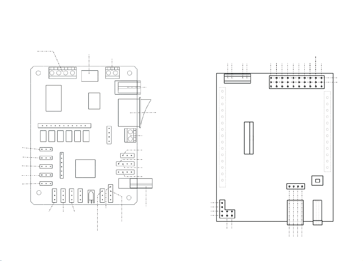
Ⅳ .Mainboard instructions
—— 51duino Mainboard
Outp ut v ol ta ge
5V out pu t
7-15 V in pu t
Swit ch
P22M ai nl ight
inte rf ac e
Arduino PWR Power-Motor driver board
Mo to r M2 +
Mo to r M2 -
Mo to r M1 +
Mo to r M1 -
PW M11
serv o2
A4
A3
A1
AO
2
A2
A5
serv o1
GND
5V
serv o1
serv o2
serv o3
serv o4
serv o5
serv o8
serv o6
/// // /// // /// // /// // /// // /// // /// // /// // /// // /// // /// // /// // /// // /// // /// // /// // 5 / /// // /// // /// // /// ///// ///// ///// ///// ///// /// // /// // /// // /// // /// // /// /// // /// // /// // /// // /// // /// // /// // /// // /// // /// // /// // /// // /// // /// // /// // // 6 // // /// // /// // /// // /// ///// ///// ///// ///// ///// /// // /// // /// // /// // /// // //
serv o7
The se ns or o f in frared obst ac le a vo idance
ultrasonic TRIG
ultrasonic ECHO
The i nf rar ed t rac in g lef t
The i nf rar ed t rac in g rig ht
The i nf rar ed f oll ow ing lef t
The i nf rared f ollow ing rig ht
USB po we r su pport
and UA RT interface
SCL
SDA
5V
GND
PWM3
4
GND
RX
TX
5V

Ⅴ.Assembly drawings
5.1 Integral wiring diagram of electronic syst em for 51 duino
Note: T he expo se d elect ronic s ys tems is p rohib ited to d o stati c te st!
Camera
USB2.0 interface
51duino Mainboard
USB2.0- Mi cr oU SB C able
WiFi m odule
5.2 Hardware installation
5.2.1 Hardware installation for 51duino
Power cab le
Battery
5.1 Integral wiring diagram of electronic system for Arduino
Note: T he expo se d elect ronic s ys tems is p rohib ited to d o stati c te st!
Arduino Mainboa rd
Camera
Power cable
USB2.0- Mi cr oU SB C able
WiFi module
BatteryUSB2.0 interface
5.2.1 Hardware installation for Arduino
PW R Power & M ot or- Driver
Arduino UNO R3 Main boa rd
/// // /// // /// // /// // /// // /// // /// // /// // /// // /// // /// // /// // /// // /// // /// // /// / 7 // /// // /// // /// // /// ///// ///// ///// ///// ///// /// // /// // /// // /// // /// // / /// // /// // /// // /// // /// // /// // /// // /// // /// // /// // /// // /// // /// // /// // /// // / 8 /// // /// // /// // /// // /// ///// ///// ///// ///// ///// /// // /// // /// // /// // /// // //

5.2.2 Robot Link WiFi installation
a) . Use s hor t nylon col umns to fix WiF i board in TH Robo t
b) . Use l ong nylon c olumns to fix W iFi board in DS Robot
5.2.3 Assembly drawings for Camera and Cradle
Servo whe el may not su itable for cradle,ma nual cut it
Follow the drawin gs to install t he cradle , use screw to fix parts
(1)
【Spe cial at tenti on】Note : whe n insta lling n ylon co lumn to t he Wi Fi modu le, it is i mpor tan t
to no te that r esi sta nce in R6 8 mar k on the Wi Fi modu le.We s ugg est c lamp nu t not m oving ,
and u se the ro tat ing way t o ins tall th e colum n nylon o n the oth ersid e, othe rwis e the r ota ry
nut i n this si de of is li kel y to le ad to R 68 re sis tan ce touc h off b y ext ern al fo rces.
/// // /// // /// // /// // /// // /// // /// // /// // /// // /// // /// // /// // /// // /// // /// // /// / 9 // /// // /// // /// // /// ///// ///// ///// ///// ///// /// // /// // /// // /// // /// // / / // /// // /// // /// // /// ///// ///// ///// ///// ///// ///// /// // /// // /// // /// // /// // 1 0 /// // /// // /// // /// // /// // /// // /// // /// // /// // /// // /// // /// // /// // /// ///// //
(2)

(3)
(4)
assemble the parts of cradle a nd servos
5.2.3 Assembly drawings for Camera and Cradle
Came ra a nd C radle install at io n
(5)
Final product
/// // /// // /// // /// // /// // /// // /// // /// // /// // /// // /// // /// // /// // /// // /// // /// 11 / /// // /// // /// // /// // /// // /// // /// // /// // /// // /// // /// // /// ///// ///// /// /// // /// // /// // /// // /// // /// // /// // /// // /// // /// // /// // /// // /// // /// // /// // / 12 // // /// // /// // /// // /// ///// ///// ///// ///// ///// /// // /// // /// // /// // /// // ///

5.2.3 Assembly drawings for Camera and Cradle
The connection of cra dle with 51duino main board
serv o8
serv o7
The connection of cra dle with Arduino main board
serv o2
serv o1
serv o7
serv o8
The connection of s er vo:
The yellow one is PWM
The red one is VCC
The brown one is GND
/// // /// // /// // /// // /// // /// // /// // /// // /// // /// // /// // /// // /// // /// // /// // /// 1 3 // /// // /// // /// // /// ///// ///// ///// ///// ///// /// // /// // /// // /// // /// // //
serv o1
serv o2
The connection of s er vo:
The yellow one is PWM
The red one is VCC
The brown one is GND
/// // /// // /// // /// // /// // /// // /// // /// // /// // /// // /// // /// // /// // /// // /// // // 14 / // /// // /// // /// // /// ///// ///// ///// ///// ///// /// // /// // /// // /// // /// // ///

5.2.4 Motors assembly(DS only)
Moto rs Inst allat ion tut orial
Motor connect installation
M1-
M1+
Parallel co nn ec t th e same side of mo to rs i n cr oss ,then c on ne ct
to motor in te rf ac e M1 +,M1- or M2+, M2 - in m ai nb oard.
Motor installation
/// // /// // /// // /// // /// // /// // /// // /// // /// // /// // /// // /// // /// // /// // /// // /// / 15 / /// // /// // /// // /// ///// ///// ///// ///// ///// /// // /// // /// // /// // /// // // /// /// // /// ///// ///// ///// ///// ///// ///// /// // /// // /// // /// // /// // /// // /// // / 16 // // /// // /// // /// // /// // /// // /// // /// // /// // /// // /// // /// ///// ///// ///// //

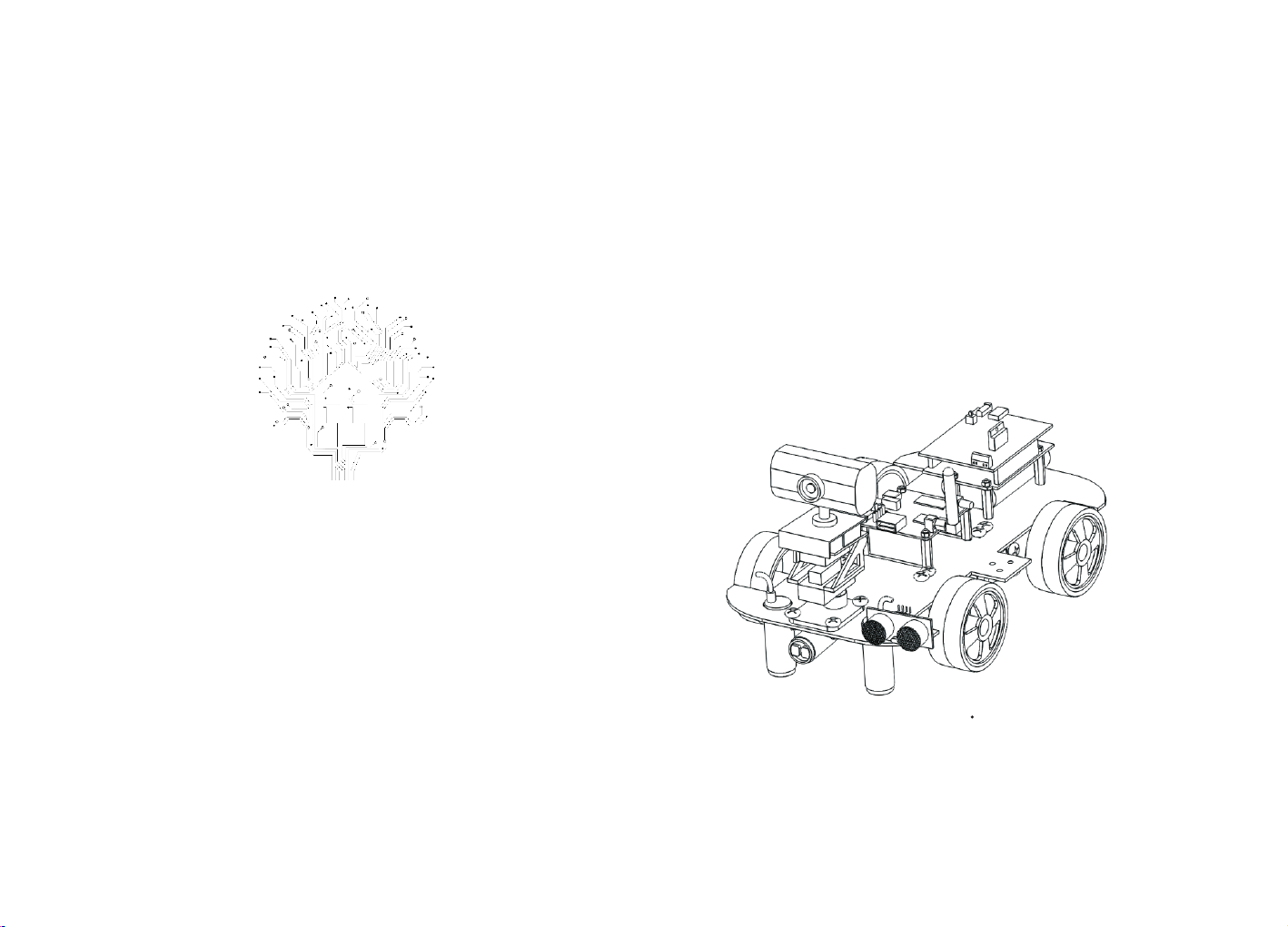
5.3 Assembly drawings overview for DS Robot
Installation of electronic systems Ⅰ
Mainboard(51duino o r Arduino)
batt er y
Installation of electronic systems Ⅱ
Mainboard
WiFi module
Camera and Cradle
/// // /// // /// // /// // /// // /// // /// // /// // /// // /// // /// // /// // /// // /// // /// // /// 1 7 // /// // /// // /// // /// ///// ///// ///// ///// ///// /// // /// // /// // /// // /// // // //// /// // /// // /// // /// // /// // /// // /// // /// // /// ///// ///// ///// ///// ///// ///// 1 8 /// // /// // /// // /// // /// // /// // /// // /// // /// // /// // /// // /// // /// // /// // /// /

Extras functions of Sensors and mode switch
6.1 The instruction of Arduino sensors with full functions
6.1 The instruction of 51duino sensors with full functions
refer to page 13
The right sensor of
automatic tracking
function P3^7
refer to page 14
The left s en so r of
automatic tracking
function P2^1
The left s en so r of
line patrol a nd a utonomous tracing/
cliff avoidance P2^3
/// // /// // /// // /// // /// // /// // /// // /// // /// // /// // /// // /// // /// // /// // /// // /// / 19 / /// // /// // /// // /// ///// ///// ///// ///// ///// /// // /// // /// // /// // /// // // /// /// // /// ///// ///// ///// ///// ///// /// // /// // /// // /// // /// // /// // /// // /// // / 20 // // /// // /// // /// // /// // /// // /// // /// // /// // /// // /// // /// ///// ///// ///// //
The middle sensor
of auto ma ti c tr ac king and Infrared
ray avoids blocke r
P3^3
ultrasonic sensors /distance
measure sensors Echo=P3^4
Trig =P 3^ 5
The right sensor of
line patrol a nd
autonomous tracing/
cliff avoidance
The left s en so r
of line pat rol
and autonomous
tracing/ cliff avoidance A2
The middle sensor
of Infrared r ay
avoids blocke r A4
The right sensor of
line patrol a nd a utonomous tracing/
cliff avoidance A3
ultrasonic sensors /
distance measure
sensors Echo=AO
Trig =A 1

6. 2 The tutorial of switching mode in the software
Bring up the multi-functional options by pres si ng t he p ho ne m en u
or clicking the small white circl e on t he i nter fa ce
Choosing custom commands in the multi -f un ct io n op ti on s of mobile phone
Download Android APP
The switching instruction in custom command mode:
FF130100FF The following mode
FF130200FF The line patro l mo de
FF130300FF The infrared o bs ta cl e av oi da nc e mo de
FF130400FF The ultrasonic obstacle avoi da nc e mo de
FF130000FF The normal mode
/// // /// // /// // /// // /// // /// // /// // /// // /// // /// // /// // /// // /// // /// // /// // /// / 21 / /// // /// // /// // /// ///// ///// ///// ///// ///// /// // /// // /// // /// // /// // //
password:501f
APP iphone download: In apple store input "wifi-robots" download.
/// // /// // /// // /// // /// // /// // /// // /// // /// // /// // /// // /// // /// // /// // /// // / 22 // // /// // /// // /// // /// ///// ///// ///// ///// ///// /// // /// // /// // /// // /// // ///

Ⅶ. Operation instructions to the product(PC)
1.Turn on the power switch of robot, the LED lights of Wifi module
and main control board start blinking, wait about 30 seconds, the
LED lights of Wifi module and main control board is always on, the
LED light of 51duino main control board is closed, it represents the
system is star ting competely.
2.Use the computer's wireless to search the hot spot signal of
robot, our hot spot is "wifi-robots.com" at the beginning of list,
then connect.
4.WASD is default operation of controlling four directions movement with robot in the keyboard .Choosing 'Auxiliary function '- '
The mouse and cradle of camera ' , then the users can drag
and control the movement of camera and cradle in video.
3.Starting the software of PC, choose the 'control mode'-'WiFi
mode' on the top of the sof tware, if there is no error in software
interface, the users can start controlling the robot.
/// // /// // /// // /// // /// // /// // /// // /// // /// // /// // /// // /// // /// // /// // /// // /// / 23 / /// // /// // /// // /// ///// ///// ///// ///// ///// /// // /// // /// // /// // /// // //
5.More functions reference the "help" option of software.
/// // /// // /// // /// // /// // /// // /// // /// // /// // /// // /// // /// // /// // /// // /// // // 24 / // /// // /// // /// // /// ///// ///// ///// ///// ///// /// // /// // /// // /// // /// // ///

Ⅶ. Operation instructions to the product(PHONE/PAD)
1.Open the power switch of robot, the L ED lights of Wifi module
and main control board start blinking, wait about 30 seconds, the
LED lights of Wifi module and main control board is always on, the
LED light of 51duino main control board is closed, it represents the
system is star ting competely.
2.Use the phone's wireless to search the hot spot signal of robot,
our hot spot is "wifi-robots.com" at the beginning of list, then
connect.
The default mode of operation is the circular cotrol board
on the interface to control the directions of robot movement .
Using the fingers slide screen can control the cradle of robot.
Open the software in mobile phone , select start item ,the user
can cotrol the robot if see the real-time video screen . The users
may need to activate the software at first time using by long pressing activation information to copy ID of mobile phone ,and send
it to the customer
servicer.
/// // /// // /// // /// // /// // /// // /// // /// // /// // /// // /// // /// // /// // /// // /// // /// / 25 / /// // /// // /// // /// ///// ///// ///// ///// ///// /// // /// // /// // /// // /// // //
Finding more functions in software prompts.
/// // /// // /// // /// // /// // /// // /// // /// // /// // /// // /// // /// // /// // /// // /// // // 26 / // /// // /// // /// // /// ///// ///// ///// ///// ///// /// // /// // /// // /// // /// // ///

VIII.
FCC NOTE
This device complies with part 15 of the FCC Rules. Operation is
subject to the condition that this device does not cause harmful
interference (1) this device may not cause harmful interference, and
(2) this device must accept any interference received, including
interference that may cause undesired operation.
Changes or modifications not expressly approved by the party
responsible for compliance
could void the user's authority to operate the equipment.
NOTE: This equipment has been tested and found to comply with
the limits for a Class B digital device, pursuant to Part 15 of the FCC
Rules. These limits are designed to provide reasonable protection
against harmful interference in a residential installation. This
equipment generates, uses and can radiate radio frequency energy
and, if not installed and used in accordance with the instructions,
may cause harmful interference to radio communications. However,
there is no guarantee that interference will not occur in a particular
installation.
If this equipment does cause harmful interference to radio or
television reception,
which can be determined by turning the equipment off and on,
the user is encouraged to try to correct the interference by one or
more of the following measures:
-- Reorient or relocate the receiving antenna.
-- Increase the separation between the equipment and receiver.
-- Connect the equipment into an outlet on a circuit different
from that to which the receiver is connected.
-- Consult the dealer or an experienced radio/TV technician for
help.
To maintain compliance with FCC’s RF Exposure guidelines, This
equipment should be installed and operated with minimum
distance between 20cm the radiator your body: Use only the
supplied antenna.
FCC ID: 2AI8ADSR51XR1MTPLA
 Loading...