

Page 1

Intelligent Gateway Device
ZF190
Operating Instructions
V1.0.0
Xi’an ZFE Technology Co., Ltd.
Page 2

Statement
All rights reserved, without the written permission of the company, the contents of any
paragraph in this manual shall not be extracted, copied or reproduced or transmitted in any form,
otherwise all consequences will be made by the offender.
The company reserves the right to modify the product specifications described in this manual
without prior notice.Before ordering, please contact the factory for the latest specifications of this
product.
Page 3

兆孚®
XI’AN ZFE TECHNOLOGY CO.,LTD
029-88469134 www.xaZFE.com
Table of Contents
1、Introduction ................................................................................................................................ 1
2、System structure diagram ........................................................................................................... 1
3. Technical characteristics ............................................................................................................... 2
4、Interface description and function description .......................................................................... 2
5、Technical Parameters .................................................................................................................. 4
6. Web browser parameter settings ................................................................................................. 6
7、Dimensions (147mm×103mm×42mm) .................................................................................... 10
~ 3 ~
Page 4
兆孚®
1、Introduction
and file transfer. It reads data from terminal devices such as data collectors and sensors locally, and communicates
via RS485 or CAN. Read data from the DTU device. After the reading is completed, the data of the DTU device is
periodically stored in the internal SD to store the history of the device. At the same time, it connects with the
remote background server, and uploads the historical data files in the SD to the remote background server through
the FTP protocol. For background server queries. The device has 2 RS485 communication, 2 CAN communication,
1 SD card storage, 1 GPRS/3G/4G network communication, 4 DI, 4 DO.
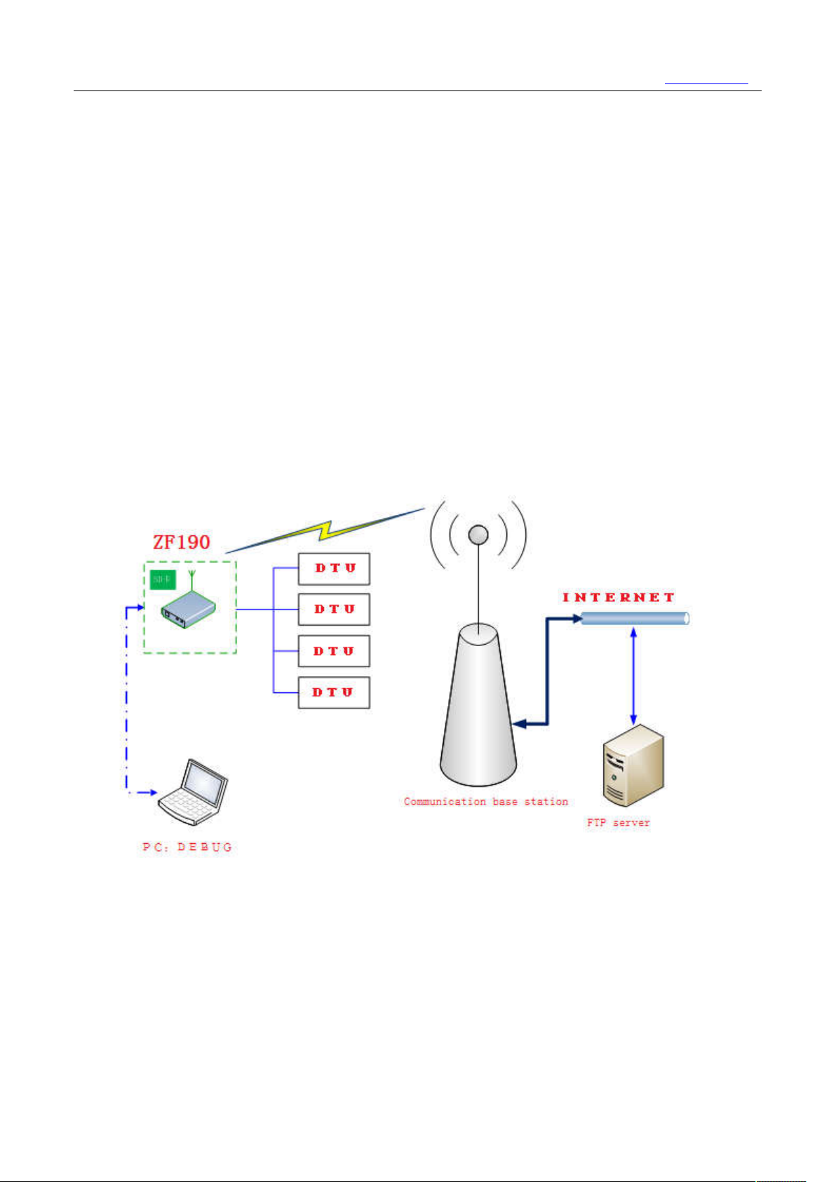
2、System structure diagram
The intelligent gateway device ZF190 is a product that specializes in the application of remote data reading
XI’AN ZFE TECHNOLOGY CO.,LTD
029-88469134 www.xaZFE.com
2.1 Network link:
(1) PC (or laptop) and gateway connected by RJ45 network cable
(2) Gateway and telecom base station are connected through air interface
(3) FTP server and telecom base station are connected through network cables, switches, routers, and optical
fibers.
2.2 Data transmission path:
(1)The gateway obtains grid data from the meter via the 485 bus.
(2) The gateway processes the data and stores it in the SD card in the gateway box.
1
Page 5

兆孚®
XI’AN ZFE TECHNOLOGY CO.,LTD
029-88469134 www.xaZFE.com
(3)The gateway transmits data to the FTP server through the network.
3. Technical characteristics
High performance, low power consumption, high reliability with NXP (formerly Freescale) i.MX
6UltraLite processor。
●All components of the core module reach the industrial temperature range of -40 to 85 °C
● Built-in super capacitor, at least 15 seconds after the power is cut off, to ensure that the
transaction information is not lost.
● Modular design, which can quickly provide customized services for customers' individual needs
● 4 channels DI, 4 channels DO, 2 channels 485, 2 channels CAN, all with electrical isolation and
interface protection, safe and reliable
●Upgrade the system with SD card, no need to disassemble the shell, simple and convenient
● Wide voltage range, safe and reliable operation in the range of 9 to 15V, and built-in super capacitor,
no fear of voltage fluctuation
●It adopts aluminum alloy profile shell with ear volume of only 147×103×42mm. It is compact in size,
beautiful in appearance and easy to install.
● Comprehensive status indicator, system operation, network communication, interface connection...
all conditions at a glance
●Multiple communication methods, onboard 100M network port, Bluetooth and Wi-Fi, 4G (or GPRS) module
●Standard DB9 debug serial port
● Standard SD card slot, support SD, SDHC and SDXC card, maximum measured capacity 64G, easy to expand
local storage space
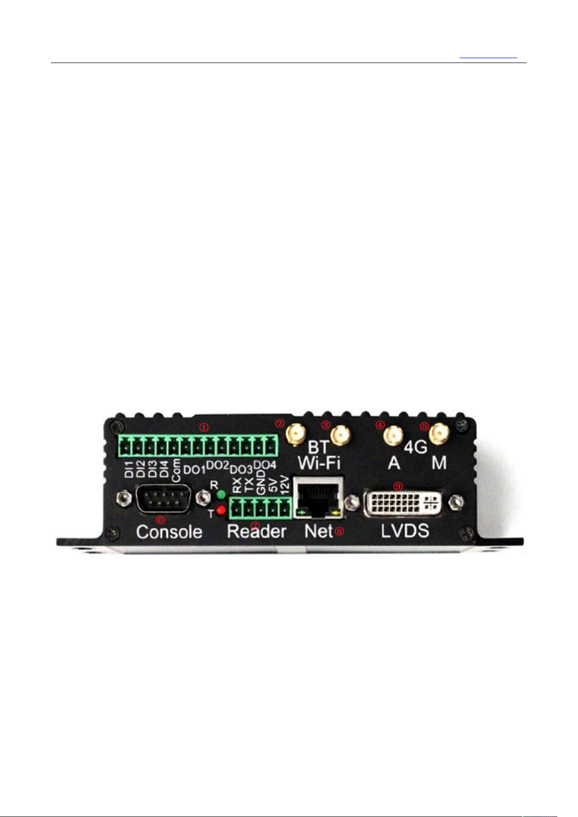
4、Interface description and function description
(1) 4G/GPRS status indicator.
(2) 8 digits 3.81mm pitch green terminal contains 4 interfaces, from left to right: RS-485-1,
RS-485-2, CAN1, CAN2.These interfaces are electrically isolated from the CPU and the function
2
Page 6
兆孚®
(3) Two rows of LEDs are the transceiver status indicators. The two lights on the green and red
(4) Standard drawer mini SIM card slot. Above is the card of the 4G/GPRS module, below is the PSAM
(5) This machine can update the system with SD card by inserting the prepared SD card into the card
(6) 12V power outlet is a 3-digit 3.81mm pitch green terminal with 12V+ on the left and 12V- on the
(7) The left side of the power socket is the running indicator. When the power is running, the green
(8) In the middle of the two USB sockets is the power indicator, and PG is the abbreviation of Power
of each terminal is identified by the character above the terminal. For example: A1 and B1
represent A and B of the first RS-485 interface, respectively, and L1 and H1 represent L and
H of the first CAN interface, respectively.
are grouped together. There are 4 groups from left to right, which in turn correspond to the
4 interfaces of the above green terminals. The green light indicates reception and the red light
indicates transmission.
card, press the yellow button on the right side of the drawer to pop up the drawer.
slot, holding down the Boot button, clicking the Reset button, then releasing the Boot button
to boot from the SD card, waiting for the system to update itself. carry out.
right, suspended in the middle.
light is on. When the fault occurs, the red light is on. These two lights are directly driven
by the CPU's IO port and can be customized according to customer requirements.
Good. When the power supply voltage is higher than 8V, the green light is on, indicating that
the power supply is normal; otherwise, the green light is off and the CPU is informed of the
power failure. When the internal super capacitor supplies power to the whole machine, the red
light is on, indicating that the external power supply is faulty.
XI’AN ZFE TECHNOLOGY CO.,LTD
029-88469134 www.xaZFE.com
(1) 13-bit 3.81mm pitch green terminal contains 4 digital inputs and 4 digital outputs. From left to
right: Input1 to 4, Input common, and Output1 to 4. The digital input interface can withstand the
switching voltage signal within 24V DC, above 3V is high level, below 1V is low level. These input
ports are internally compatible and can be configured to supply 5V power to the unit according
to user requirements. The external only provides dry contact.
(2) Bluetooth antenna.
(3) Wi-Fi antenna.
(4) 4G secondary antenna.
(5) 4G main antenna. The main antenna is required, and the secondary antenna is used to enhance the
receiving effect. It is not necessary, but it is recommended to connect.
(6) 3-wire debug serial port, standard DB9 male socket, RS-232 level, no electrical isolation.
3
Page 7
兆孚®
(7) 5-digit 3.81mm pitch green terminal is a card reader module interface, providing one RS-232
(8) 1 standard RJ-45 network cable interface, adaptive 10M/100M Ethernet.
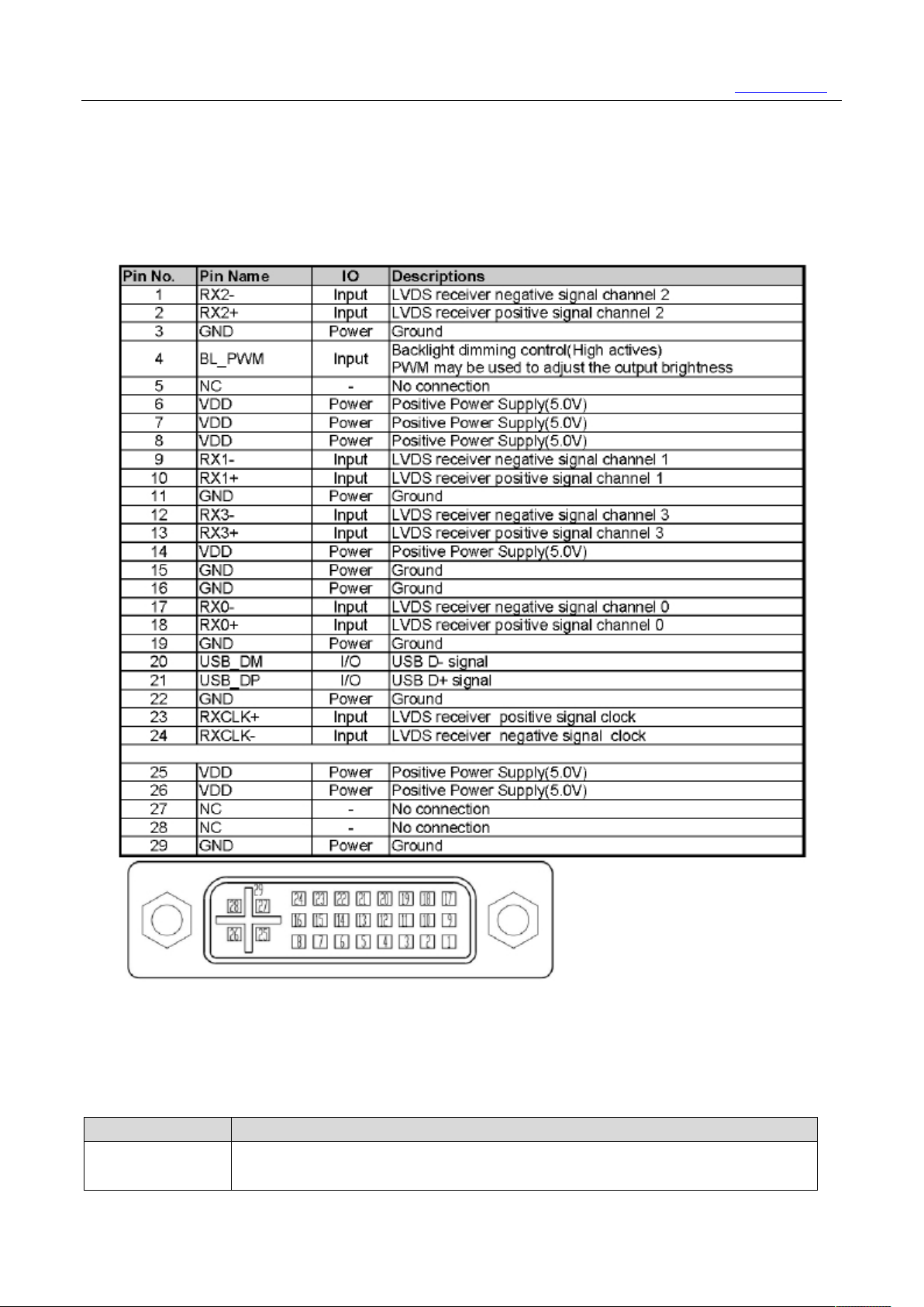
(9) The lower right corner is the LVDS interface. By default, it is connected to the LMT070DICFWD-AKA
three-wire serial port, 5V and 12V power supply
LCD monitor from Shenzhen Top Micro Technology Development Co., Ltd. The interface is defined as
follows (taken from the data sheet of the LMT070DICFWD-AKA LCD):
XI’AN ZFE TECHNOLOGY CO.,LTD
029-88469134 www.xaZFE.com
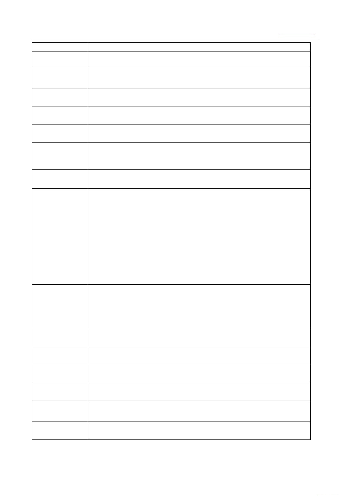
5、Technical Parameters
project parameter
CPU
NXP(原 Freescale)i.MX6UltraLite,ARM Cortex-A7 Architecture,
frequency
528MHz Main
4
Page 8
兆孚®
The four boot configuration jumpers of the backplane must be set
Standard SD card interface, support SD, SDHC, SDXC card, the maximum measured capacity
drawer type Mini SIM card slot ("SIM" logo on the right side
4 channels, electromagnetic relay isolation. Contact capacity: 1A 30VDC / 0.5A 125VAC
4 channels, optocoupler isolation, 3.81mm pitch green terminal, default configuration:
Touch color screen
When the external
High level, the PG green light on the housing lights up; otherwise it is low level,
witches to
drops by more than 10%, the whole machine is powered off, so as to
maintain at least 1 year
External storage
Mobile communication SIM800A module with drawer type Mini SIM card slot ("SIM-GPRS" logo above the card slot).
RAM 512MB LvDDR3
FLASH e.MMC 或 NandFlash,
according to the type of the core board.
is 64G SDXC card
PSAM Support PSAM card with
of the card slot)
Switch output
/ 0.3A 60VDC
Switch input
DC voltage input, 3 to 24VDC
It is judged as a high level, and 1 VDC or less is judged as a low level;
Adopt standard DVI-I socket, default to Shenzhen Top Micro's LMT070DICFWD-AKA LCD
interface
XI’AN ZFE TECHNOLOGY CO.,LTD
029-88469134 www.xaZFE.com
Power failure
response
measures
Serial port
(including RS-485)
USB 1 USB OTG interface with standard Micro USB socket
CAN BUS CAN1: CAN2.0 B, 1Mbps, electrically isolated, communicating with the charge controller
Ethernet Net1: Standard RJ-45 socket, 10M/100M adaptive for connecting to higher level system
The CPU has a GPIO dedicated to monitoring the external power state.
power supply voltage is higher than 8V, the IO is
and the PG green light is off.
When the external power supply is interrupted, the system automatically s
the built-in super capacitor power supply, and the PG red light point on the panel
bright. The super capacitor can maintain the system for at least 15 seconds while
monitoring the internal 5V mains voltage of the whole machine.
When the voltage
avoid the software abnormality caused by the system voltage being too low.
UART1: Three-wire debug serial port, DB9 socket, non-isolated, chassis ID is Console
UART2: card reader, three-wire, green terminal, non-isolated
UART3: Connect the GPRS module to the machine, not drawn
UART4: Converted to RS-485-1 in the machine, green terminal lead, electrical isolation
UART5: Converted to RS-485-2 in the machine, green terminal lead, electrical isolation
1 USB main port with standard USB Type A socket
CAN2: CAN2.0 B, 1Mbps, electrically isolated, spare
Bluetooth and
Wi-Fi
RTC Using dedicated RTC chip RX8010SJ, onboard CR2032 battery, can
Audio
Supports IEEE 802.11b/g/n 1T1R WLAN and RL-UM02WBS-8723BU-V1.2 module
Bluetooth 2.1/3.0/4.0
time
3.5mm standard stereo headphone jack with built-in mono microphone. 1W×2
speaker socket or 3.5mm can be added
5
Page 9

兆孚®
15V, with reverse connection
AKA
C, humidity
XI’AN ZFE TECHNOLOGY CO.,LTD
029-88469134 www.xaZFE.com
Power and power
consumption
size
147mm×103mm×42mm
installation 4 Φ4mm screws
working
environment
Rated voltage: 12V, can work normally in the range of 9Vprotection;
Total power consumption is less than 5W when equipped with TopView LMT070DICFWD-
LCD
Operating temperature -10 ° C ~ 70 ° C, storage temperature -40 ° C ~ 85 °
5% ~ 95% without condensation
6. Web browser parameter settings
(1) Connect your PC or laptop via a network cable
(2) Open a web browser on your PC or laptop (recommended to use google chome browser)
(3) Enter the gateway IP address http://192.168.0.232 in the address bar of the browser, and press Enter.
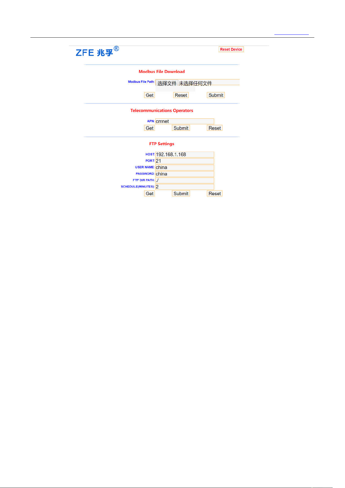
(4)The parameter configuration page is as follows:
6
Page 10
兆孚®
(1) Reset Device
Reboot the ZF190 Device
(2) Modbus File Download:
Browse the modbus config file and submit to modify the modbus config of ZF190.
(3) Telecommunications operators:
(4) FTP Settings:
USER NAME: FTP server login name
PASSWORD: FTP server login password
APN(Access Point Name): Telecom operators APN
HOST: FTP Server IP address
PORT: FTP Server port
FTP DIR PATH: Storage path of the CSV file on the FTP server
SCHEDULE(MINUTES): File upload FTP server interval
XI’AN ZFE TECHNOLOGY CO.,LTD
029-88469134 www.xaZFE.com
7
Page 11
兆孚®
XI’AN ZFE TECHNOLOGY CO.,LTD
029-88469134 www.xaZFE.com
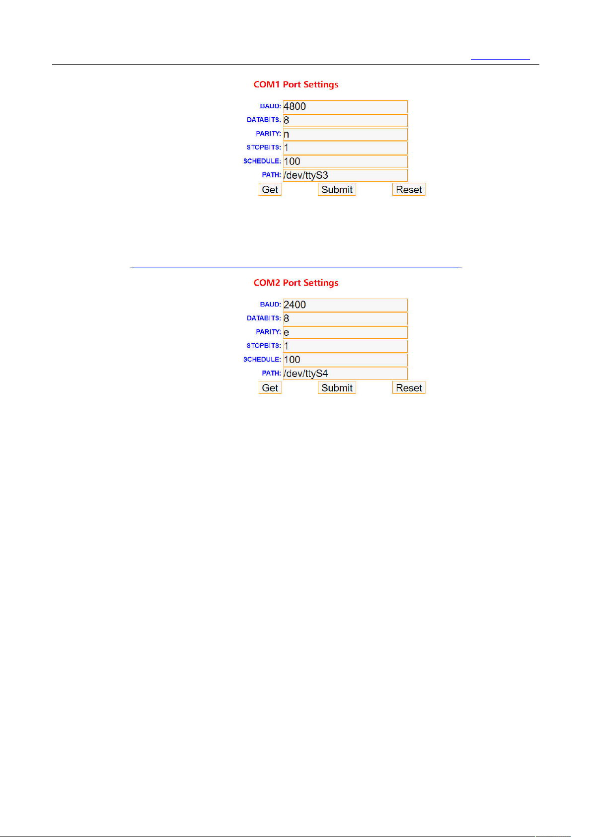
(5) COM1 Port Settings:
BAUD: 485 bus baud rate
DATABITS/PARITY/STOPBITS: Data bit/parity/stop bit
SCHEDULE: Gateway and meter communication handshake interval
PATH: File node mounted by the device on the gateway operating system
(6) COM2 Port Settings:
BAUD: 485 bus baud rate
DATABITS/PARITY/STOPBITS: Data bit/parity/stop bit
SCHEDULE: Gateway and meter communication handshake interval
PATH: File node mounted by the device on the gateway operating system
8
Page 12
兆孚®
XI’AN ZFE TECHNOLOGY CO.,LTD
029-88469134 www.xaZFE.com
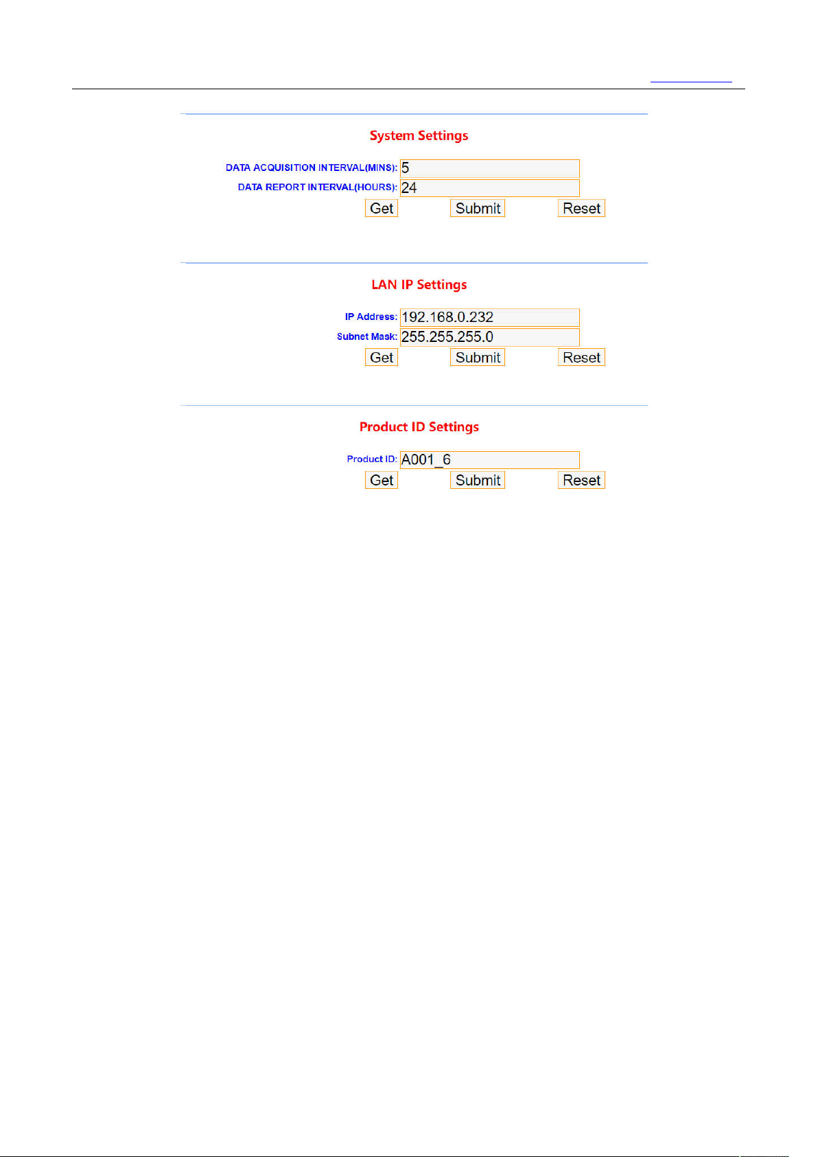
(7) System Settings:
DATA ACQUISITION INTERVAL(MINS): Data acquisition interval (unit: minute)
DATA REPORT INTERVAL(HOURS): CSV data storage interval (unit: hour)
(8) LAN IP Settings:
IP Address: Local IP Address of ZF190
Subnet Mask: Subnet Mask of ZF190
(9) Product ID Settings:
Product ID: Product ID of this Device
9
Page 13
兆孚®
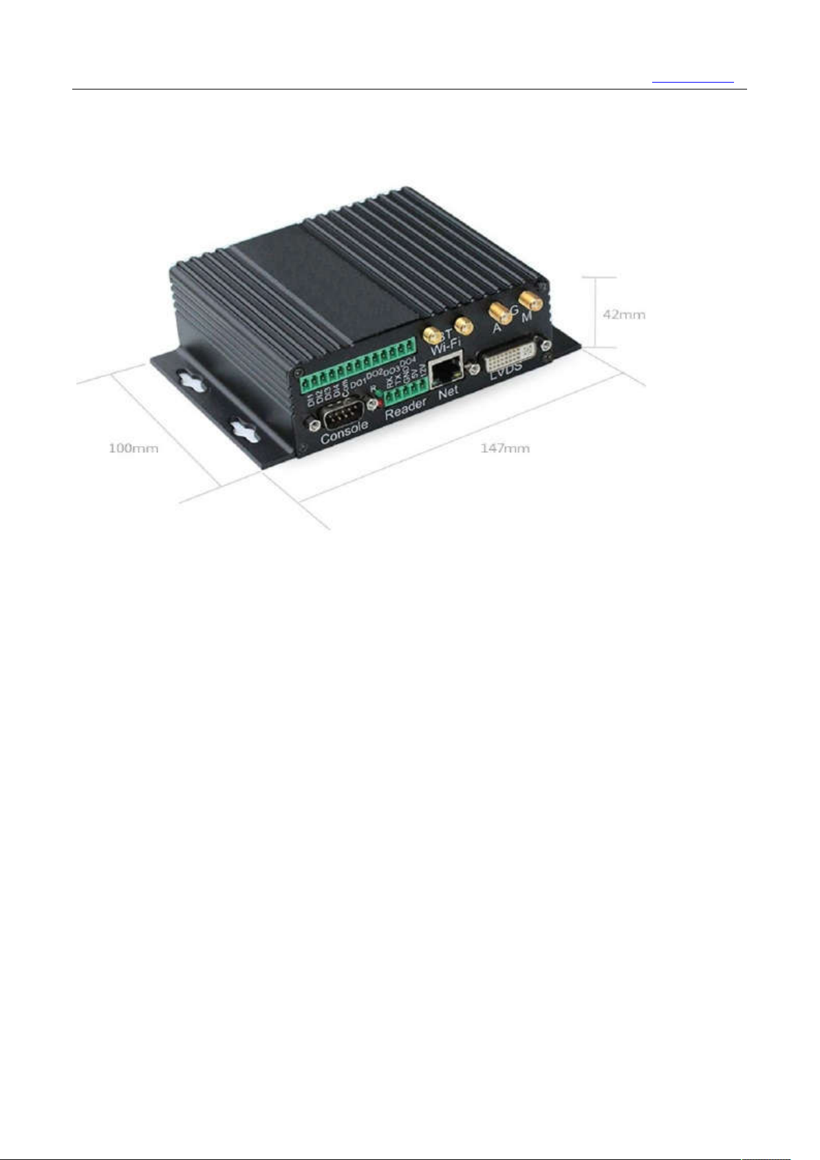
7、Dimensions (147mm×103mm×42mm)
XI’AN ZFE TECHNOLOGY CO.,LTD
029-88469134 www.xaZFE.com
4 Φ4mm screws
Positioning hole position: 47mm*135mm
10
Page 14

兆孚®
XI’AN ZFE TECHNOLOGY CO.,LTD
029-88469134 www.xaZFE.com
西安兆孚电气科技股份有限公司
XI’AN ZFE TECHNOLOGY CO.,LTD
Addr:Fengze Science and Technology Park, 170 West Avenue, High-tech Zone, Xi'an
Zip code:710000
Tel:029-88469134
Fax:029-88469134
Web:www.xazfe.com
Email:[email protected]
11
 Loading...