

1. Door sta ti on s
JB-304
(Door statio ns )
User’s manual
Model No.1 5 series
Mod el No.1 5C flus h mount
93X 168X5 2(mm)
Mod el No.1 5D flus h mount ,
car d reade r. 93X16 8X52( mm)
2. Technical parameters
Camera:
Viewing angle:
Lens:
Resolution:
Min. illumination:
Video output:
Audio SNR:
Audio distortion:
Standby current:
Work in g cu rr en t:
Work in g vo lt ag e:
Environment temperature:
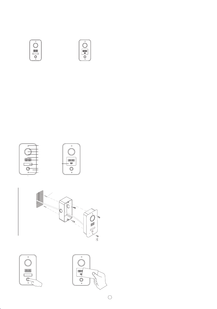
3. Structure
Scre w
LEDs
Came ra
Ligh t senso r
Cast a lumin ium pan el
Spea ker
Card r eader
Name t ag
insi de
Call b utton
Micr ophon e
Scre w
4. Installation
exp ansio n plugs
①
Box
③
5. Operation on door st at io ns
A. Call res id en ts
1/3” SONY CCD or 1/3” CMOS
92°
F=3.6
420TV Lin e
0.01 LUX
1Vp-p/75Ω
≥25dB
≤7%
≤60mA
≤230mA
DC18V±10%
-40℃ ~+ 45℃
a. Produce a groove
on a proper position of the wall( ).
b. Take off the door panel from the box
with the enclosed screw driver( ).
c. Fix the box in the groove with screws
and expansion plugs or cement( ).
d. Fix the door panel in the box with the
screws( ).
Doo r panel
②
B. Use cards to rel ea se d oo rs
(75x150x50mm)
①
②③
①
④
1
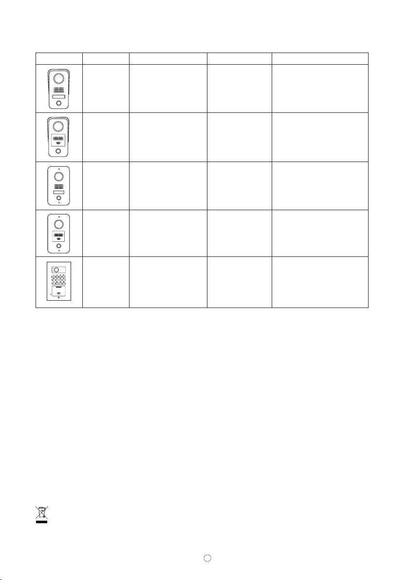
6. Door sta ti on l is t
Pro duct p ode l numbe rs Size s: L x W x D (mm ) Exclu sive fe ature shot os Mode l names S eries m
Mod el No.1 5A
Mod el No.1 5B
Mod el No.1 5C
Mod el No.1 5D
CAL L
MIC
Mod el No.1 8
JB- 304MN CW-S15
JB- 304MG CQ-S1 5
JB- 304MG CW-S15
JB- 304MN CQ-S1 5
JB- 304MC Q-S18 A
JB- 304MG CQ-S1 8A
79X 148X4 5
79X 148X4 5
93X 168X5 2
93X 168X5 2
102 X175X 39
With n ame tag a nd surf ace mou nt
With c ard rea der and s urfac e mount
With n ame tag a nd flus h mount
With c ard rea der and f lush mo unt
With k eypad
With k eypad a nd card r eader
XIMAN LEELEN TE CH NO LO GY CO.,LTD.
65, S UNBAN S OUTH RO AD, JIM EI, XIA MEN, 36 1021 CH INA
Thi s appli ance sh all not b e dispo sed tog ether
wit h the nor mal was te. It mu st be rec ycled .
Ati tude du ring op ertio n below 2 000m.
2

FCC Statement:
This device complies with part 15 of the FCC Rules. Operation is subject to the following
two conditions: (1) This device may not cause harmful interference, and (2) this device
must accept any interference received, including interference that may cause undesired
operation.
This equipment has been tested and found to comply with the limits for a Class B digital
device, pursuant to part 15 of the FCC Rules. These limits are designed to provide
reasonable protection against harmful interference in a residential installation. This
equipment generates, uses and can radiate radio frequency energy and, if not installed
and used in accordance with the instructions, may cause harmful interference to radio
communications. However, there is no guarantee that interference will not occur in a
particular installation. If this equipment does cause harmful interference to radio or
television reception, which can be determined by turning the equipment off and on, the
user is encouraged to try to correct the interference by one or more of the following
measures:
—Reorient or relocate the receiving antenna.
—Increase the separation between the equipment and receiver.
—Connect the equipment into an outlet on a circuit different from that to which the
receiver is connected.
—Consult the dealer or an experienced radio/TV technician for help.
Caution: Any changes or modifications not expressly approved by the party responsible
for compliance could void the user's authority to operate the equipment.
 Loading...