

Technology For Life
Xiamen Leelen Technology Co., Ltd.
No.65 Sunban South Road, Jimei North
Industrial Zone, Jimei District, Xiamen
National Unified Service Hotline 95105895
Website: http://en.leelen.com
The product shall be subject to the actual equipment
Access Control Reader
User’s Manual V1.0
RP.B06.ZC-SM.006
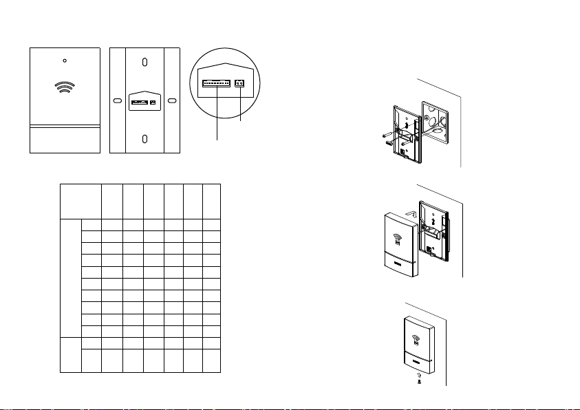
Ⅰ. Equipment Appearance View Ⅲ. Installation Diagram
1 Installation Way
1.1 Fix the rear shell with the screw to the 86 box.
CARD
Access
Lock、power supply、fire alarm、
door status detection port
control port
Ⅱ. Wiring Instructions
Digital
Access control
access
reader
control
NO black
NC white
COM grey
+ purple
- blue
10
FIRE green
cores
G yellow
socket
G orange orange
STATE red
OPEN brown
B black
Access
control
A red
port
1.2 Fasten the front shell to the back of the rear shell.
Door
Exit
Power
Fire
supply
alarm
Lock
1.3 Use the screws to tighten the front shell and rear shell,
complete the installation.
status
button
【1】 【2】

2 Installation Precautions
2.1 Before installation, please read the product instructions,
confirm the wiring mode, and ensure that the input
voltage complies with the product requirements.
2.2 Please make sure the product is used within the range of
the technical parameters; if not, this may cause damage
to the product.
2.3 Non-professionals shall not take the product apart;
otherwise, it may cause electric shock or damage to the
product.
2.4 Do not install the equipment outdoors or in heavily -dusty
places.
2.5 High voltage is dangerous! Non-professionals shall not
open the housing.
Ⅳ. Technical Specifications
Product name: Access control reader
Rated working voltage: 12~24DC
Static working current: 38mA
Maximum working current: 90mA
Environment temperature: -40℃~75
External dimension: 120*86*19.5mm
Degree of protection: IP54
V. Function
1 This device can receive the instruction sent by outdoor unit or
digital access controller, so that the lock controlled by this
device can be opened normally.
2 When receiving the swiping card information, the card data can
be uploaded to the digital access controller so that the digital
access controller can unlock the corresponding door.
3 This device has anti-dismantle, anti-removal detecting and
alarm function.
4 When the effective card is recognized, the access control reader
emits "beep" sound and then it emits a long “beep” sound;
When the invalid card is recognized, the "beep" sound emitted
by the access control reader is followed by two short bursts of
“beep” sound
5 Users can use the IC cardto unlock
【3】
【4】

Ⅵ. Dial Switch Ⅶ. Restricted Substances
The equipment has three dialing switches, dial switch 1 is low,
3 is high, and the representative address information is shown in
the following table.
3 2 1 Address
ON ON ON
ON ON
ON ON
ON
OFF
OFF
OFF
OFF
OFF
OFF OFF
ON ON
ON
OFF
OFF OFF
OFF
OFF
【5】 【6】
ON
1
2
3
4
5
6
7
8
Name
Metal part
Plastic part
CRT display
screen
LCD screen
Circuit board
component*
Power cord/
cable
Power/
adapter
Packaging
This form was prepared in accordance with SJ/T 11364 *:
It indicates that the contents of the hazardous substance in all
O:
homogeneous materials of the part are below the limit requirement
specified in GB/T 26572
X: It indicates that the contents of the hazardous substance in at least
one of the homogeneous materials of the part exceed the limit
requirement specified in GB/T26572
*: Circuit board components include a printed circuit board and its
components, such as resistors, capacitors, integrated circuits, etc.
Toxic and hazardous substances or elements
Part
(Pb) (Hg) (Cd) (Cr6+) (PBB) (PBDE)
O O O O O O
O O O O O O
X O O O O O
O O O O O O
X O O O O O
X O O O O O
X O O O O O
O O O O O O

* FCC
This device complies with Part 15 of the FCC Rules. Operation is subject to
the following two conditions:
(1) this device may not cause harmful interference, and
(2) this device must accept any interference received, including interference
that may cause undesired operation.
Changes or modifications not expressly approved by the party responsible
for compliance could void the user’s authority to operate the equipment.
This equipment has been tested and found to comply with the limits for a
Class B digital device, pursuant to Part 15 of the FCC Rules. These limits are
designed to provide reasonable protection against harmful interference in a
residential installation. This equipment generates, uses and can radiate radio
frequency energy and, if not installed and used in accordance with the
instructions, may cause harmful interference to radio communications.
However, there is no guarantee that interference will not occur in a particular
installation.
If this equipment does cause harmful interference to radio or television
reception, which can be determined by turning the equipment off and on,
the user is encouraged to try to correct the interference by one or more of the
following measures:
-- Reorient or relocate the receiving antenna.
-- Increase the separation between the equipment and receiver.
-- Connect the equipment into an outlet on a circuit different from that to
which the receiver is connected.
-- Consult the dealer or an experienced radio/TV technician for help.
【7】
 Loading...