


Warnings:
1. The intercom system including an outdoor station,an indoor station and a power supply. Please read this manual
before installation, and then install it according to this instruction.
2. To avoid the danger of electric shock,please make sure that the power system is off before installation or
maintenance.
3. If you are not a professional, please do not disassemble the shell to avoid electric shock.
4. Only the TF card is configured, will the video recording function be available. You can purchase TF cards and
install it on the indoor station according to your own needs.
Description of product model
Product Name ModelSequence No.
Model 15 Two Wires
Digital Outdoor Station
User Manual
EH2W-OS-M55-006
2
3
4
EH2W-OS-M55-007
EH2W-OS-M55-008
Model 15 Two Wires Digital Outdoor Station1
Model 15 Two Wires Digital Outdoor Station
Model 15 Two Wires Digital Outdoor Station
Model 15 Two Wires Digital Outdoor StationEH2W-OS-M55-009
FP.EH2W.OS.M55
Contents
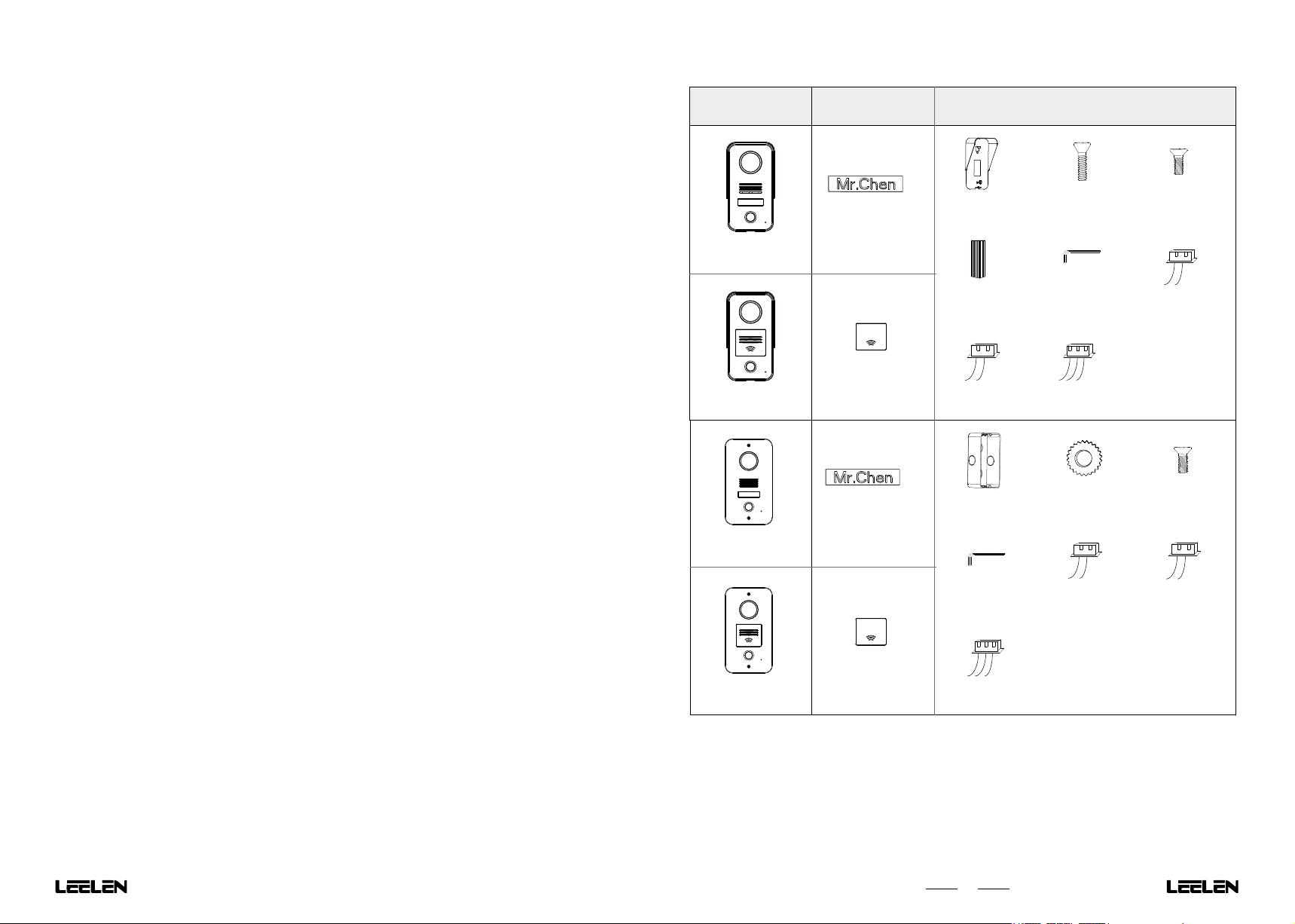
1. Contents of the Package
1. Contents of the Package .............................................................................................................................................
2. Product Description.....................................................................................................................................................
2.1 Product appearance(Four types)...........................................................................................................................
2.2 Main Technical Parameters ...................................................................................................................................
3. System Installation.......................................................................................................................................................
3.1 Wire Assignment and Distance..............................................................................................................................
3.2 Connection Diagram...............................................................................................................................................
3.2.1 One to One Kit................................................................................................................................................
3.2.2 Multi to Multi Kit..............................................................................................................................................
3.2.3 Lock Connection Instructions .........................................................................................................................
3.3 Installation..............................................................................................................................................................
3.3.1 Surface Mounted Installation..........................................................................................................................
3.3.2 Flush Mounted Installation .............................................................................................................................
3.3.3 Replace Nameplate of Outdoor Station............................................................................................................
4. Parameter Settings.......................................................................................................................................................
4.1 Enter Setting Function.............................................................................................................................................
4.2 Outdoor Station Parameter Settings........................................................................................................................
4.2.1 Parameter Setting List....................................................................................................................................
4.2.2 Outdoor Station Name....................................................................................................................................
4.2.3 Removing Alarm Setting.................................................................................................................................
4.2.4 Ring-back Tone Setting...................................................................................................................................
4.2.5 Card Management..........................................................................................................................................
4.2.6 Unlocking Setting............................................................................................................................................
4.2.7 IP Setting........................................................................................................................................................
5. Description of the System Functions...............................................................................................................................
5.1 Call,Intercom and Leave Message................................................................................................................................
5.2 Monitor...................................................................................................................................................................
5.3 Unlock by Card ......................................................................................................................................................
5.4 Unlock by Exit Button..............................................................................................................................................
FCC ................................................................................................................................................................................
Toxic and hazardous substances or elements ................................................................................................................
1
2
2
3
3
3
3
3
4
5
6
6
6
6
7
7
7
7
7
7
7
7
8
8
8
8
8
9
9
10
11
M55-001
M55-002
M55-003
M55-004
Different IdenticalOutdoor Station
Nameplate
Card reader
Nameplate
Card reader
×1
×2
Rain shield
×3
Expansion tube
×3
Wire(2.54)
×1
×2
Embedded box
×1
×2
Screws
×1
Screw driver
×1
Wire(2.54)
×2
Copper nut
×1
×1
Screws
×1
Wire(2.0)
×1
Screws
×3
Screw driver Wire(2.54)Wire(2.0)
×1
Wire(2.54)
1
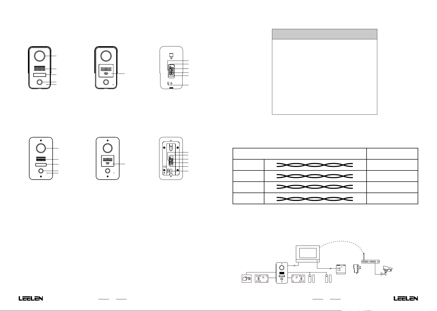
2. Product Description
2.2 Main Technical Parameters
2.1 Product appearance(Four types)
EH2W-OS-M55-001
1
2
3
4
5
1. Camera
2. Loudspeaker
3. Nameplate
4. Call Button
EH2W-OS-M55-003
1
2
3
4
5
EH2W-OS-M55-002
6
5. Microphone
6. Card Reader
7. 2-wire Communication Port
8. Exit Port
EH2W-OS-M55-004
6
7
8
9
10
11
12
9. Lock2 Port
10. Lock1 Port
11. Door Status Detector Port
12. Anti-dismantle Alarm Trigger
7
8
9
10
11
12
Camera 1/4 CMOS
Video format 1080p
Working voltage 24V
Operation mode Mechanical key
Max power consumption 5W
Standby power consumption 1W
Ingress protection IP54
CardType IC card
Card capacity 100
Working temperature -40℃~ 55℃
External dimensions(mm) 79×146×45(
(W×H×D)
93×168×32(M55-003/M55-004)
3. System Installation
3.1 Wire Assignment and Distance
Wire Assignment
AWG21
AWG22
Outdoor Station
M55-001/M55-002)
Length(m)
80
80
1. Camera
2. Loudspeaker
3. Nameplate
4. Call Button
5. Microphone
6. Card Reader
7. 2-wire Communication Port
8. Exit Port
2
9. Lock2 Port
10. Lock1 Port
11. Door Status Detector Port
12. Anti-dismantle Alarm Trigger
AWG23
AWG24
3.2 Connection Diagram
3.2.1 One to One Kit
A. System Expansion Diagram
Exit Button
Lock 1
2-wire
Lock 2 Door Open
Detector 1
WiFi
2-wire
Power Supply
Door Open
Detector 2
3
80
80
Power
or
Adaptor
IPCamera

B. Standard Installation
B. Standard Installation
DoorBell
DoorBell
DoorBell
Exit Button
InDoor Station
-
Bus
Power+
Power-
Bus+
110/220V AC
~
NLGnd
N L
Exit Port
Gnd
Bus-
Bus+
Door1 Open
Gnd
Door2 Open
Door2 Open
Detector
Door1 Open
Detector
-
Power
- -
OutDoor Station
Power+
+ +
Switch-
Switch+
NO
COM
NC
Power
Power Supply
or
Adaptor
Switch Output
(Lock2)
Power Control
Output(Lock1)
Power-
110/220V AC
~
-
Power
- -
Adaptor
DoorBell
DoorBell
Power+
+ +
Power+
Power
NLGnd
N L
Power
Power Supply
DoorBell
or
InDoor Station
3.2.3 Lock Connection Instructions
Power+
EH2W-MD-D04-001
2-Wires Digital
Power 1 2 3 4 5 6 7 8
Distributor
LAN : 10/100M
Bus : 10M
Power: 24VDC
2-Wire Digital Distributor
Bus+
Bus-
Bus+
Bus-
Bus+
Bus-
Bus+
Bus-
Bus+
Bus-
Connect to other Indoor/Outdoor Station
Exit Button
-
Bus
Bus+
-
Bus-
Bus+
Bus+
Bus-
Bus+
Bus-
Exit Port
Gnd
Bus -
Bus+
Door1 Open
Gnd
Door2 Open
Door2 Open
Detector
Door1 Open
Detector
OutDoor Station
Switch-
Switch+
NO
COM
NC
Switch Output
(Lock2)
Power Control
(Lock1)
Output
3.2.2 Multi to multi Kit
A. System Expansion Diagram
EH2W-MD-D04-001
2-Wires Digital
Distributor
LAN : 10/100M
Bus : 10M
Power: 24VDC
2-wire
2-wire
Power 1 2 3 4 5 6 7 8
Power Supply
2-wire
2-wire
Power Control Output (Lock1)
Note:
If the lock is opened by stopping power supply, the lock
+12V
Unlock
COM
NC
Gnd
NO
Power
or
Adaptor
WiFi
WiFi
Switch Output(Lock2)
Unlock
Switch -
Switch +
IPCamera
4
should be connected to NC and COM terminals, and the normal
working current of the lock is no more than 800mA.
If the lock is opened by power supply to the lock, the lock shall
be connected to the NO and COM terminals, and the current is
no more than 800mA when the lock is opened.
Note:
Lock 2 is the signal output mode, which is normally
disconnected and connected when the lock is opened.
The maximum voltage supported by lock 2 is 24VDC and the
maximum current is less than or equal to 800mA.
5

3.3 Installation
3.3.1 Surface Mounted Installation
Wall
Rain Shield
M3 Self-tapping
Door Panel
Screw
3.3.2 Flush Mounted Installation
Wall
Embedded Box
Door Panel
1. Drill the hole at the appropriate height on the
wall, and then insert the rubber plug into the
hole on the wall.
2. Fix the rain shield on the wall with the screw.
3. Connect the wire to the outdoor station.
4. Fix the outdoor station to the rain shield with
the screw.
1. Trepan a hole in the appropriate position on
the wall, insert the embedded box in the
wall slightly, and fix it with the cement slurry.
2. Connect the wire to the outdoor station.
3. Fix the outdoor station of which a sponge pad is
pasted at the alarm trigger, and lock the outdoor
station with the screw.
4. Parameter Settings
4.1 Enter Setting Function
1 1
08:22am
2018/08/08 Monday
Record Monitor Privacy Screen LockIntercom Settings
1. Touch the 「 」Icon.
4.2 Outdoor Station Parameter Settings
4.2.1 Parameter Setting List
Outdoor Station Settings
Name
Cards
About
Removal Alarm
Unlocking
IP Address
Ring-back tone
Set outdoor station parameters
Set system parameters
Set indoor station parameters
2. The indoor station shows
the setting list page.
System Parameters
Outdoor Station1Outdoor Station2
Indoor Station1 Indoor Station2
Note: If the outdoor stations or the indoor stations is not
connected, the outdoor station settings icon and
the indoor station settings icon will be missing.
4.2.2 Outdoor Station Name
Outdoor Station Settings
Name
Removal Alarm
Input OS Name
Ring-back tone
Cards
About
Outdoor Station1
Unlocking
IP Address
Home
Screw
3.3.3 Replace Nameplate of Outdoor Station
1.Push down and push to the left. 2.Take out the nameplate.
3.Change the nameplate sticker. 4.Push down and push to the right.
4.2.3 Removing Alarm Setting
Outdoor Station Settings
Name
Removal Alarm
Removal alarm
Ring-back tone
About
Cards
Unlocking
IP Address
4.2.4 Ring-back Tone Setting
Sounds
Volume:
25% 50% 75% 100%
0%
4.2.5 Card Management
1/1 No.
Card No. Time
1
01022238 2018-07-10 10:02:22
2
2018-07-10 10:02:2202013366
6
1. Press the 「Registering Card」
button to start.
2. The indoor station shows
registration cards page.
3. User can swip all cards on the
outdoor station.
4. The indoor station shows
how many cards have been registered.
5. User can press the call button
to finish registration.
7
1/1 No.
Card No. Time
1
1111-0001 2018-07-10 10:02:22
2
3
6. User also can press the finish
button to finish registration.
2018-07-10 10:02:22
1111-0002
2018-07-10 10:02:22
1111-0003
Registering Cards:01
Finish

4.2.6 Unlocking Setting
4.2.7 IP Setting
5.3 Unlock by Card
5.4 Unlock by Exit Button
Unlocking
Lock1 Delay Time(s)
Lock2 Delay Time(s)
Lock1 door sensor
Door open delay alarm
Lock2 door sensor
Door open delay alarm
5
20
IP Address
Subnet Mask
Router
DNS
Manual Setting
Note:
The router address of the outdoor station
should be filled in with the IP address of the
main indoor station.
5. Description of the System Functions
5.1 Call,Intercom and Leave Message
Answer
Hang up
2. The indoor station shows the ring page.
1. The visitor pushes the call button.
Note:
If the equipment with a TF card, video will be recorded automatically when the bell rings. Otherwise, take a photo
snap.
In intercom, you can press
In intercom,you can press
In intercom, press the 「 」 to expand other function buttons.
For leave message,the visitor can press the call button to leave a message after hearing message notice and press
the call button to end talking after leaving a message.
「 」or「 」to open the corresponding door.
「 」to switch the monitor video,then you can view other monitoring video.
Open the door 1
Open the door 2
Switch the IPC video
More
User can open the outdoor station’s
Lock1 by the registered card.
For the card registration, see the
description(4.2.5) in the parameter
settings section.
Exit Button
User can open the outdoor station’s
Lock1 by press the Exit Button.
5.2 Monitor
1 1
08:22am
2018/08/08 Monday
Record Monitor Privacy Screen Lock Intercom Settings
4. The indoor station shows
the monitor page.
Note:
In the monitoring state, press the 「 」 to
initiate a call to the outdoor station,so that you
can talk to someone outside the door.
1. User press the Monitor icon.
2. The indoor station shows
the monitor list.
3. User press the Outdoor
Station icon or IPC icon
to monitor the video.
8
Monitor List
Outdoor Station1 Outdoor Station2 IPC1
IPC2 IPC3 IPC4
Return
Call
Open the door 1
Open the door 2
Switch the IPC video
More
9

This device complies with Part 15 of the FCC Rules. Operation is subject to the following two conditions:
(1) this device may not cause harmful interference, and (2) this device must accept any interference
received, including interference that may cause undesired operation.
The statements should be displayed in the user manual:
changes or modifications not expressly approved by the party responsible for compliance could void the
user’s authority to operate the equipment.
Part Name
Toxic and hazardous substances or elements
Lead
(Pb)
Mercury
(Hg)
Cadmium
(Cd)
Hexavale
nt nobeliu
m(Cr6 +)
Polybromi
nated biph
enyl
(PBB)
Polybromi
nated diph
enylether
(PBDE)
This equipment has been tested and found to comply with the limits for a Class B digital device, pursuant
to Part 15 of the FCC Rules. These limits are designed to provide reasonable protection against harmful
interference in a residential installation. This equipment generates, uses and can radiate radio frequency
energy and, if not installed and used in accordance with the instructions, may cause harmful interference
to radio communications. However, there is no guarantee that interference will not occur in a particular
installation.
If this equipment does cause harmful interference to radio or television reception, which can be determined
by turning the equipment off and on, the user is encouraged to try to correct the interference by one or more
of the following measures:
-- Reorient or relocate the receiving antenna.
-- Increase the separation between the equipment and receiver.
-- Connect the equipment into an outlet on a circuit different from that to which the receiver is connected.
-- Consult the dealer or an experienced radio/TV technician for help.
Metal Part
Plastic Part
CRT display
screen
LCD screen
Circuit board
component*
Power/
cord/cable
Power/
adapter
Packaging
O
O
X
O
X
X
X
O
O
O
O
O
O
O
O
O
O
O
O
O
O
O
O
O
O
O
O
O
O
O
O
O
O
O
O
O
O
O
O
O
*: Circuit board components include a printed circuit board and its components,
such as resistors, capacitors, integrated circuits, etc.;
O
O
O
O
O
O
O
O
O: It indicates that the contents of the hazardous substanse in all homogeneous
materials of the part are below the limit requirement specified in IEC62321;
X: It indicates that the contents of the hazardous substanse in at least one of the
homogeneous materials of the part exceed the limit requirement specified in
IEC62321;
Technical specifications and contents are subject to change without notice.
RoHS
10
11
 Loading...