


V31 Two Wires
Digital Indoor Station
Warnings:
1)
The intercom system including an outdoor station,an indoor station and a power supply. Please read this manual
before installation, and then install it according to this instruction.
2)
To avoid the danger of electric shock,please make sure that the power system is off before installation or
maintenance.
3)
If you are not a professional, please do not disassemble the shell to avoid electric shock.
4)
Only the TF card is configured, will the video recording function be available. You can purchase TF cards and install
it on the indoor station according to your own needs.
RP.V31.ZC-SM.006
User Manual
Contents
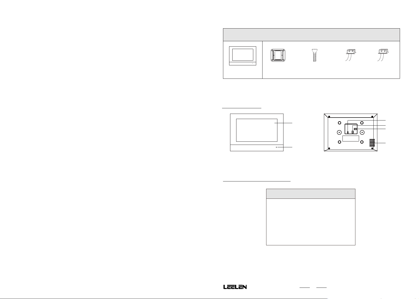
1. Contents of the Package
1. Contents of the Package .............................................................................................................................................
2. Product Description......................................................................................................................................................
2.1 Indoor Station..........................................................................................................................................................
2.2 Main Technical Parameters ...................................................................................................................................
3. System Installation........................................................................................................................................................
3.1 Wires and Distance.................................................................................................................................................
3.2 Connection Diagram...............................................................................................................................................
3.2.1 One to One Kit...............................................................................................................................................
3.2.2 Multi to Multi Kit..............................................................................................................................................
3.3 Installation..............................................................................................................................................................
4. Parameter Settings.......................................................................................................................................................
4.1 Enter Setting Function.............................................................................................................................................
4.2 System Parameter Settings ....................................................................................................................................
4.3 Indoor Station Parameter Settings............................................................................................................................
5. Description of the System Functions..............................................................................................................................
5.1 System Functions...................................................................................................................................................
5.2 Call, Intercom and Leave Message..........................................................................................................................
5.3 Monitor.....................................................................................................................................................................
5.4 Privacy.....................................................................................................................................................................
5.5 Screen Lock.............................................................................................................................................................
5.6 Record Views..........................................................................................................................................................
5.7 Anti-Dismantle Alarm...............................................................................................................................................
FCC ................................................................................................................................................................................
Restricted Substances ....................................................................................................................................................
1
1
1
1
2
2
2
2
3
4
5
5
5
6
7
7
7
8
8
8
8
9
9
10
EH2W-IS-V31
2. Product Description
2.1 Indoor Station
1. Touch Screen
2. Microphone
3. Doorbell Port
2.2 Main Technical Parameters
Bracket Screw(M4*20PMC)
×1
Indoor Station
1
2
×2
4. Power Supply Port
5. 2-wire Communication Port
6. Loudspeaker
×1
×2
Wire(2.54)Wire(2.0)
3
4
5
6
Indoor Station
LCD screen 1024×600
Working voltage 24V DC
Max power consumption 3.5W
Standby power consumption 1.5W
Ingress protection IP30
Working temperature -20℃~ +55℃
External dimensions 200mm × 140mm ×18mm
1
(W×H×D)
3. System Installation
B. Standard Installation
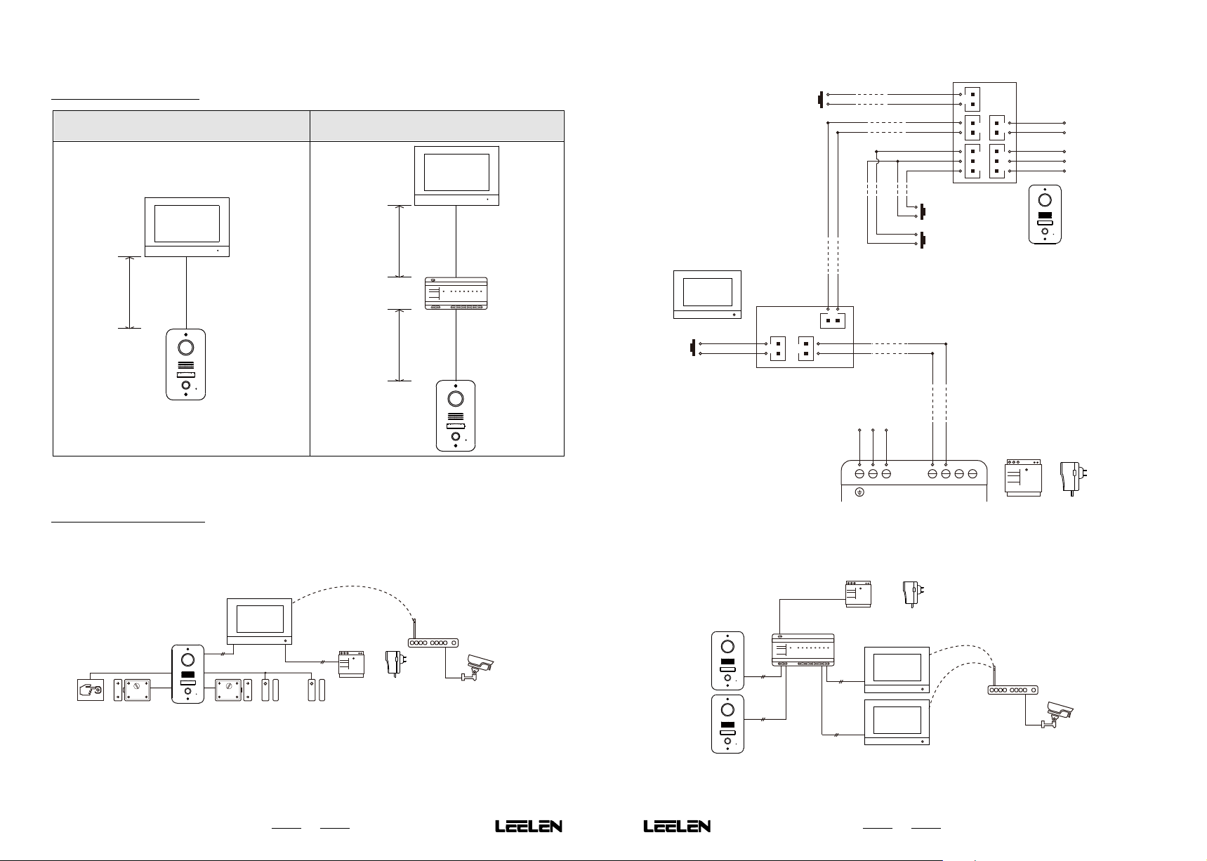
3.1 Wires and Distance
One to One Kit
A
The maximum distance of A is 80 meters. The supported wires include AWG21, AWG22,AWG23 and AWG24.Single
strand and twisted pair.
Multi to Multi Kit
A
EH2W-MD-D04-001
2-Wires Digital
Distributor
LAN : 10/100M
Bus : 10M
Power: 24VDC
A
Power 1 2 3 4 5 6 7 8
3.2 Connection Diagram
3.2.1 One to One Kit
A. System Expansion Diagram
Exit Button
Indoor Station
DoorBell
DoorBell
DoorBell
3.2.2 Multi to Multi Kit
A. System Expansion Diagram
-
Bus
Power+
Power-
Bus+
110/220V AC
~
NLGnd
N L
Exit Port
Gnd
Bus-
Bus+
Door1 Open
Gnd
Door2 Open
Door2 Open
Detector
Door1 Open
Detector
-
Power
- -
Outdoor Station
Power+
+ +
Switch-
Switch+
NO
COM
NC
Power
Power Supply
or
Adaptor
Switch Output
(Lock2)
Power Control
Output(Lock1)
Exit Button
Lock 1
Outdoor
Station
2-wire
Indoor
Station
Lock 2 Door Open
Detector 1
WiFi
2-wire
Power Supply
Door Open
Detector 2
2
Power
or
2-Wire Digital
Distributor
EH2W-MD-D04-001
2-Wires Digital
Power 1 2 3 4 5 6 7 8
Distributor
LAN : 10/100M
Bus : 10M
Power
or
Adaptor
IPCamera
Power: 24VDC
2-wire
Power Supply
2-wire
Adaptor
WiFi
WiFi
2-wire
Outdoor Station
2-wire
Indoor Station
IPCamera
3

B. Standard Installation
4. Parameter Settings
110/220V AC
~
NLGnd
N L
Power
Power Supply
DoorBell
3.3 Installation
Indoor station
or
Adaptor
DoorBell
DoorBell
-
Power
Power+
+ +
- -
Indoor Station
Power+
Power-
EH2W-MD-D04-001
2-Wires Digital
Distributor
LAN : 10/100M
Bus : 10M
Power: 24VDC
2-Wire Digital Distributor
Bus+
Bus-
Bus+
Bus-
Connect to other Indoor/Outdoor Station
-
Bus
Bus+
Power+
Power
-
Bracket
86-Box
Dimersion 86*86mm
Power 1 2 3 4 5 6 7 8
Bus+
Bus-
Bus+
Bus-
Exit Button
Bus+
Bus-
Bus+
Bus-
Bus+
Bus-
Bus+
Bus-
Outdoor Station
Exit Port
Gnd
Bus -
Bus+
Door1 Open
Gnd
Door2 Open
Door2 Open
Detector
Door1 Open
Detector
Switch-
Switch+
NO
COM
NC
1. Fix the bracket to the 86 box or wall
with the M4 * 20 screw.
2. Connect the wire to the equipment.
3. Put the indoor station on the bracket.
Switch Output
(Lock2)
Power Control
(Lock1)
Output
4.1 Enter Setting Function
1 1
08:22am
2018/08/08 Monday
Record Monitor Privacy Screen LockIntercom Settings
1. Touch the 「 」Icon.
4.2 System Parameter Settings
4.2.1 Parameter Setting List
System Parameters
Language
Call Duration
Message
4.2.3 Time Setting
Date
Time
Time Zone
Date Format
Time Format置
4.2.5 Privacy Setting
Y/M/D
12H 24H
2018/08/08
12:35
GMT+8
M/D/Y
Time
Privacy
IPC
D/M/Y
Set outdoor station parameters
Set system parameters
Set indoor station parameters
2. The indoor station shows the
setting list page.
Note: If the outdoor stations or the indoor stations is not
connected, the outdoor station settings icon and
the indoor station settings icon will be missing.
4.2.2 Language Setting
Return
4.2.4 Call Duration Setting
Note: Call duration is 30s~120s,please set in the range.
System Parameters
Outdoor Station1Outdoor Station2
Indoor Station1 Indoor Station2
System Parameters
English
français
Türk
Polski
Privacy
Call Duration(s)
45
Privacy
Time
IPC
IPC
IPC
Time
Time
IPC
IPC
Language
Call Duration
Message
System Parameters
Language
Call Duration
Message
Home
ScrewM4*20PMC
21:00-07:00
13:00-14:00
Repetition
Sun Mon Tues Wen
Sun Mon Tues
No. Time
1
2
4
Delete all privacy settings
Add a new privacy
Touch the record to
modify
5
Add Privacy Time
Start Time
End Time
Repetition :
21:00
12:35
Tues
Mon
Sun
Wen
SatThur
Fri

4.2.6 Message
System Parameters
Message function
Language
Default
Ring Time
Custom
Message
Time
Privacy S
IPC
Play the default
message.
Play the custom
message.
Record the custom
message.
4.3 Indoor Station Parameter Settings
4.3.1 Parameter Setting List
Indoor Station Settings
Name Main Indoor Unit
IP Settings
4.3.3 Main Indoor Station Setting
Indoor Station Settings
IP Settings
4.3.5 Brightness Setting
Indoor Station Settings
IP Settings
4.3.7 WiFi Setting
1/1
Brightness Sounds
Wifi Settings
About
About
Name Main Indoor Unit
Main Indoor Station
Extension
Brightness Sounds
Wifi Settings
About
About
Name Main Indoor Unit
20% 40%
80%
60%
Brightness Sounds
100%
Wifi Settings
About
About
WiFi
Network Access WiFi List
4.2.7 IPC Setting
IPC
IPC1
IPC2 IPC3
IPC5
IPC4
4.3.2 Indoor Station Name
Indoor Station Settings
Name Main Indoor Station
Input indoor station name
indoor station1
About
About
Brightness Sounds
Wifi Settings
IP Settings
4.3.4 Sounds Setting
Sounds
Ring1
Ring4
25%
5
Ring2 Ring3
Ring5
50% 75% 100%
Ring duration(1~120s)
Ring
Volume
4.3.6 IP Setting
Manual Setting
IP Address
Subnet Mask
Router
DNS
4.3.8 About
Device Information
Hardware Version:
Software Version:
Upgradable Version:
Web address:
Restore the factory settings
Delete all IPCs
Add new IPC
Touch the icon
to modify
5. Description of the System Functions
5.1 System Functions
Function Description
Monitor
Access control Open the door through intercom or swiping a card.
Alarm Door timeout alarm and device removal alarm.
Record and management
Unlock by card Support swiping card to open the door.
Exit button terminals Support Exit Button to open the door.
5.2 Call,Intercom and Leave Message
5.2.1 Outdoor Station to Indoor Station
2. The indoor station shows the ring page.
1. The visitor press the call button.
Note:
If the indoor station with a TF card, video will be recorded automatically when the bell rings. Otherwise, take a
photo snap.
In intercom, you can press
In intercom,you can press
In intercom, press the
For leave message, please check the description of 4.2.6 first.The visitor can press the call button to leave a
message after hearing message notice and press the call button to end talking after leaving a message.
5.2.2 Indoor Station to Indoor Station
08:22am
2018/08/08 Monday
Record Monitor Privacy Screen Lock Intercom Settings
Support indoor station and mobile phone monitoring the outdoor station video and
IPC video.
Support video recording with TF card and capturing without TF card.
「 」or「 」to open the corresponding door.
「 」to switch the monitor video,then you can view other monitoring video.
「 」to expand other function buttons.
1 1
1. User press the Intercom button.
2. The indoor station shows
the indoor station list.
3. User press the Indoor Station
icon which you want to call.
Indoor Station List
Indoor Station 1 Indoor Station 2
Indoor Station 3 Indoor Station 4
Answer
Hang up
Open the door 1
Open the door 2
Switch the IPC video
More
6
7

5.3 Monitor
5.7 Anti-Dismantle Alarm
1 1
08:22am
2018/08/08 Monday
Record Monitor Privacy Screen Lock Intercom Settings
4. The indoor station shows
the monitor page.
Note:
In the monitoring state, press the 「 」 to
initiate a call to the outdoor station,so that you
can talk to someone outside the door.
5.4 Privacy
1 1
08:22am
2018/08/08 Monday
Record Monitor Privacy Screen Lock Intercom Settings Record Monitor Privacy Screen Lock Intercom Settings
5.5 Screen Lock
1 1
08:22am
2018/08/08 Monday
Record Monitor Privacy Screen Lock Intercom Settings
1. User press the Monitor icon.
2. The indoor station shows
the monitor list.
3. User press the Outdoor Station
icon or IPC icon to monitor the
video.
1. User press the Privacy icon.
2. Press「 」button to turn on
privacy mode.
1. User press the Screen Lock
icon.
2. Press「 」button to clean,
and the indoor station will
lock the screen for 1 minute.
Monitor List
Outdoor Station1 Outdoor Station2 IPC1
IPC2 IPC3 IPC4
Return
Call
Open the door 1
Open the door 2
Switch the IPC video
More
Privacy mode on?
08:22
am
2018/07/09 Monday
08:22
am
Clean mode on?
2018/07/09 Monday
Record Monitor Privacy Screen Lock Intercom Settings
1 1
08:22am
2018/08/08 Monday
Removal alarm!
Record Monitor Privacy Screen Lock Intercom Settings
Once the outdoor station was removed, the indoor station
will receive a voice prompt and record the event.
1 1
FCC
This device complies with Part 15 of the FCC Rules. Operation is subject to the following two conditions:
(1) this device may not cause harmful interference, and (2) this device must accept any interference received,
including interference that may cause undesired operation.
The statements should be displayed in the user manual:
1 1
changes or modifications not expressly approved by the party responsible for compliance could void the user’s
authority to operate the equipment.
This equipment has been tested and found to comply with the limits for a Class B digital device, pursuant to Part 15
of the FCC Rules. These limits are designed to provide reasonable protection against harmful interference in a
residential installation. This equipment generates, uses and can radiate radio frequency energy and, if not installed
and used in accordance with the instructions, may cause harmful interference to radio communications. However,
there is no guarantee that interference will not occur in a particular installation.
5.6 Record Views
08:22am
2018/08/08 Monday
Record Monitor Privacy Screen Lock Intercom Settings
If this equipment does cause harmful interference to radio or television reception, which can be determined by
turning the equipment off and on, the user is encouraged to try to correct the interference by one or more of the
1 1
1. User press the Record icon.
2. The indoor station shows
the record list.
3. User can press the record
to view the detail info.
1/1 No.
1
2
3
4
5
6
7
8
9
2018-07-10 10:02
2018-07-10 09:42
2018-07-10 09:31
2018-07-10 08:52
2018-07-10 08:07
2018-07-10 07:52
2018-07-09 17:02
2018-07-09 16:42
2018-07-09 12:32
OtherTime
following measures:
-- Reorient or relocate the receiving antenna.
-- Increase the separation between the equipment and receiver.
-- Connect the equipment into an outlet on a circuit different from that to which the receiver is connected.
-- Consult the dealer or an experienced radio/TV technician for help.
This equipment complies with FCC radiation exposure limits set forth for an uncontrolled environment. This
equipment should be installed and operated with minimum distance 20cm between the radiator and your body. This
transmitter must not be co-located or operating in conjunction with any other antenna or transmitter.
8
9

Restricted Substances
Toxic and hazardous substances or elements
Part Name
Metal Part
Plastic Part
CRT display
screen
LCD screen
Circuit board
component*
Power/
cord/cable
Power/
adapter
Lead
(Pb)
O
O
X
O
X
X
X
Mercury
(Hg)
O
O
O
O
O
O
O
Cadmium
(Cd)
O
O
O
O
O
O
O
Hexavale
nt nobeliu
m(Cr6 +)
O
O
O
O
O
O
O
Polybromi
nated biph
enyl
(PBB)
O
O
O
O
O
O
O
Polybromi
nated diph
enylether
(PBDE)
O
O
O
O
O
O
O
Packaging
O
O
O
O
*: Circuit board components include a printed circuit board and its components,
such as resistors, capacitors, integrated circuits, etc.;
O: It indicates that the contents of the hazardous substanse in all homogeneous
materials of the part are below the limit requirement specified in IEC62321;
X: It indicates that the contents of the hazardous substanse in at least one of the
homogeneous materials of the part exceed the limit requirement specified in
IEC62321;
Technical specifications and contents are subject to change without notice.
RoHS
10
O
O
 Loading...