

Xiamen Intretech SMART User Manual
1132-05-SRevamp – IRON PCB
PCB specification
SMART Manual
Approval by
Checked by
Originated by
LS CMO
KFL
Page 1 5/3/2017 12:08:00 PM
1132-05-SRevampIRON-PCBSpec-V5.docx
This document contains confidential and/or privileged information. Any unauthorized distribution of this document is strictly prohibited.
1132-05-SRevamp – IRON PCB
PCB specification
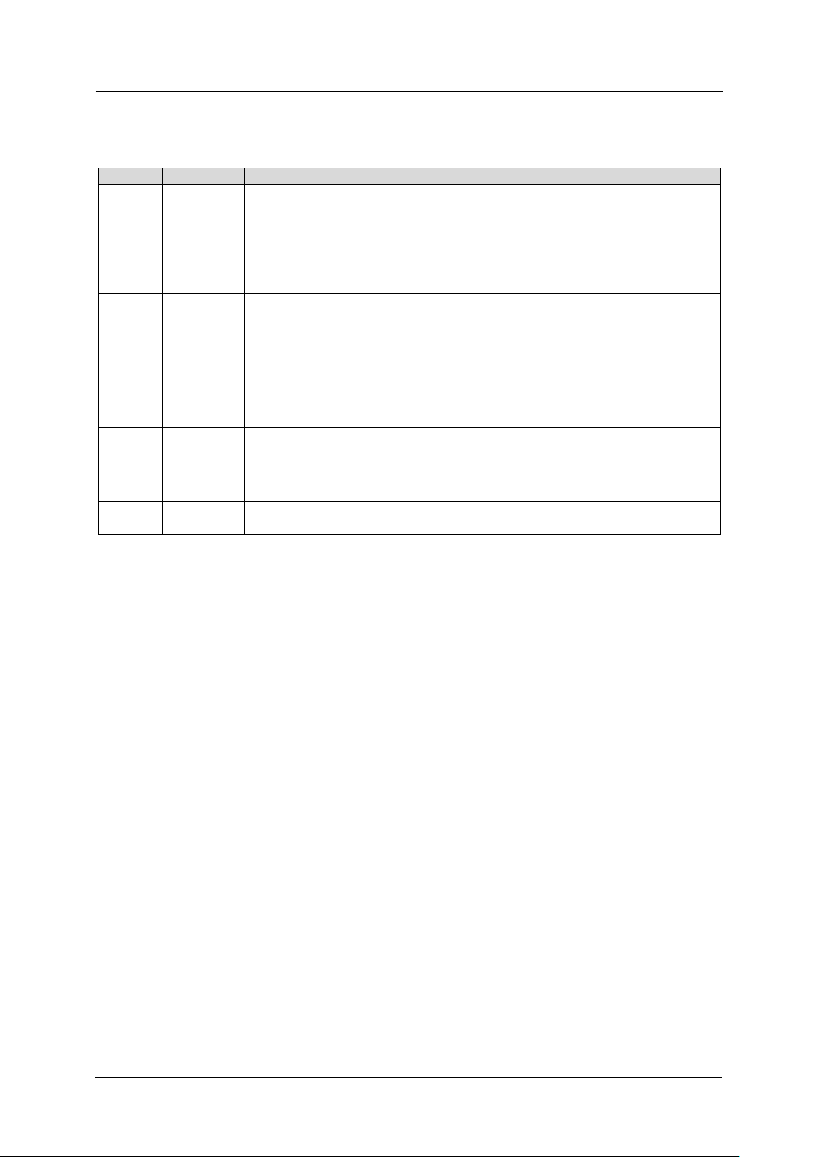
Versions
Version
Date
Editor
Modifications
1
01-09-2016
KFL
Initial release
2
10-10-2016
CMO
• Base for testing instructions
• Modify for cypress touch Chip version
• Cypress flashing FW instructions
• Changed to Accelerometer ST version
• Add the MAC label information
3
07-12-2016
CMO
• Completed the Production tests (especially DTM)
• Modified the QR code to a barre code
• Updated to V7 (BOM-SCH-Layout)
• Removed the Prog connector
4
17-02-2017
CMO
• Updated the TDE Iron position Info for Accelero.
• Updated the FW versions
5
03-05-2017
CMO
• Updated the BOM with alternates and Matched
antenna values
• Updated FW version for SOP
Page 2 5/3/2017 12:08:00 PM
1132-05-SRevampIRON-PCBSpec-V5.docx
This document contains confidential and/or privileged information. Any unauthorized distribution of this document is strictly prohibited.

1132-05-SRevamp – IRON PCB
PCB specification
Table of content
Contents
Versions 2
Table of content .................................................................................................................................................. 3
1 FCC Statement........................................................................................................................... 4
2 ISED statements ........................................................................................................................ 5
3 Notice to OEM integrator ............................................................................................................ 6
4 Machine label ............................................................................................................................. 6
Contains FCC ID : S96SMART , Contains IC: 22175-SMART ......................................................................... 6
5 Introduction 6
6 Mechanical specification ............................................................................................................ 7
7 Cables 8
8 Electrical specification ................................................................................................................ 8
9 PCB MAC Sticker ....................................................................................................................... 9
10 PCB specification ..................................................................................................................... 11
Property of SDATAWAY SA Page 3 5/3/2017 12:08:00 PM
1132-05-SRevampIRON-PCBSpec-V5.docx
This document contains confidential and/or privileged information. Any unauthorized distribution of this document is strictly prohibited.
1132-05-SRevamp – IRON PCB
PCB specification
1 FCC Statement
This device complies with part 15 of the FCC Rules. Operation is subject to the following two conditions:
(1) This device may not cause harmful interference, and (2) this device must accept any interference
received, including interference that may cause undesired operation
Caution: The user is cautioned that changes or modifications not expressly approved by the party
responsible for compliance could void the user's authority to operate the equipment.
Note: This equipment has been tested and found to comply with the limits for a Class B digital device,
pursuant to part 15 of the FCC Rules. These limits are designed to provide reasonable protection against
harmful interference in a residential installation. This equipment generates, uses and can radiate radio
frequency energy and, if not installed and used in accordance with the instructions, may cause harmful
interference to radio communications. However, there is no guarantee that interference will not occur in
a particular installation. If this equipment does cause harmful interference to radio or television reception,
which can be determined by turning
the equipment off and on, the user is encouraged to try to correct the interference by one or more of the
following measures:
—Reorient or relocate the receiving antenna.
—Increase the separation between the equipment and receiver.
—Connect the equipment into an outlet on a circuit different from that to which the receiver is connected.
—Consult the dealer or an experienced radio/TV technician for help.
CFR 47 FCC PART 15 SUBPART C has been investigated. It is applicable to the modular transmitter.
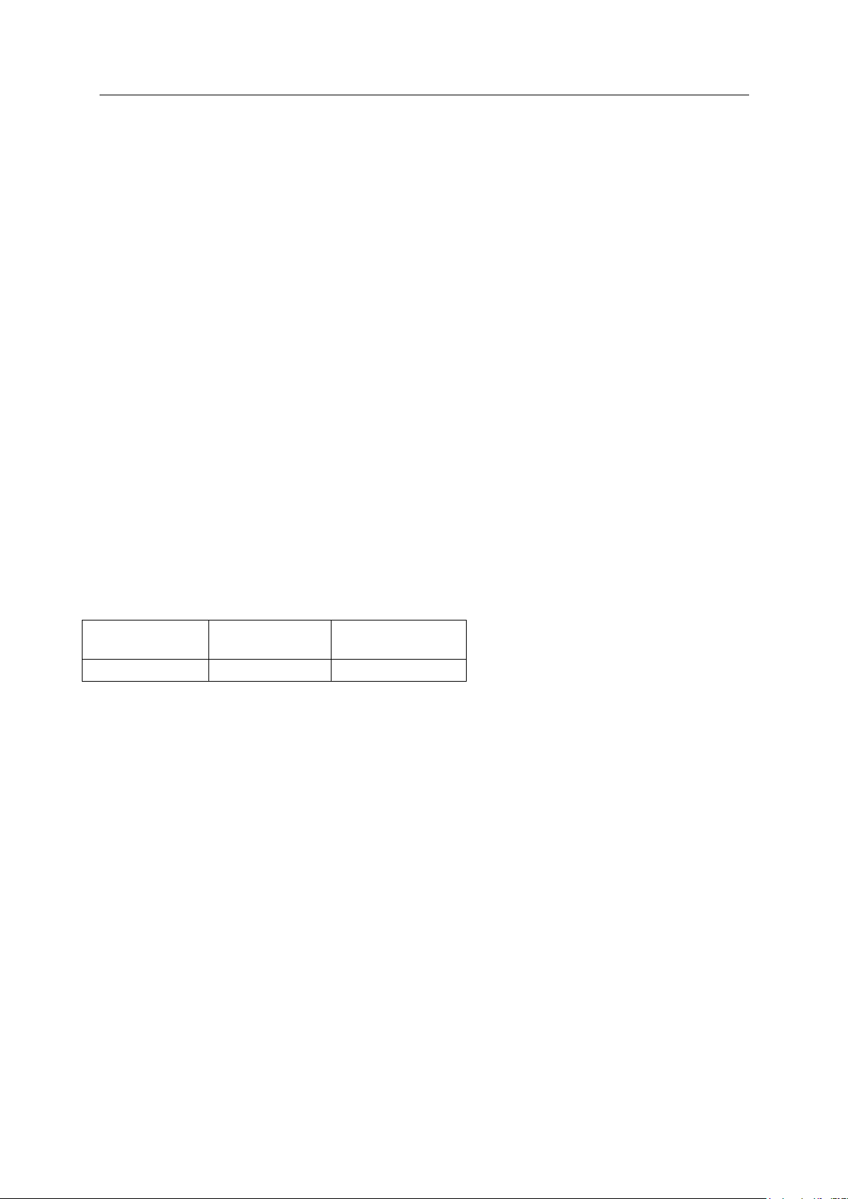
This radio transmitter S96SMART has been approved by Federal Communications Commission to
operate with the antenna types listed below, with the maximum permissible gain indicated. Antenna
types not included in this list that have a gain greater than the maximum gain indicated for any type
listed are strictly prohibited for use with this device.
Frequency (MHz)
Antenna Type
Antenna Gain
(dBi)
2402-2480
Chip
1.0
 Loading...