

Xiaguang XP XG2045 User Manual

ADSL2+ Tester Contents
72-0046-03A 1
Contents
1. Overview..........................................................................................................3
1.1 Symbol Descriptions........................................................................................3
1.2 Product Overview............................................................................................3
1.3 Basic Functions..............................................................................................4
1.4 Main Features................................................................................................5
1.5 Product Composition.......................................................................................6
1.6 General Specifications.....................................................................................8
2. Getting Started...............................................................................................10
2.1 General Information......................................................................................10
2.2 Unpacking Check..........................................................................................10
3. Manipulation...................................................................................................11
3.1 LED Indicators..............................................................................................11
3.2 Functional Keyboard......................................................................................13
3.3 Preparations for Operation..............................................................................15
3.4 Brief Menu Introduction.................................................................................15
3.5 Communication with PC.................................................................................16
3.6 Rechargeable Batteries and Charge..................................................................17
3.7 Power Management.......................................................................................20
3.8 Safety Precautions........................................................................................20
4. Navigating the Displays...................................................................................24
4.1 Menu Structure............................................................................................24
4.2 “Settings” Menu............................................................................................26
4.3 “Results” Menu.............................................................................................41
4.4 “Storages” Menu...........................................................................................50
4.5 “Others” Menu..............................................................................................53
5. Performing Measurements...............................................................................57
5.1 Overview.....................................................................................................57
5.2 Basic Information.........................................................................................57
5.3 Performing Measurements..............................................................................61

ADSL2+ Tester Contents
72-0046-03A 2
6. Working with TestManagerPro........................................................................65
6.1 Software Functions........................................................................................65
6.2 System Configuration and Running Environment.................................................65
6.3 Install and Uninstall the Software on the PC.......................................................66
6.4 How to Use TestManagerPro............................................................................66
7. Troubleshooting.............................................................................................69
8. Glossary.........................................................................................................70

ADSL2+ Tester 1 Overview
72-0046-03A 3
1. Overview
This chapter is intended to give first-time users a quick overview of the symbols used in the
manual, the main functions, features, compositions and the general specifications of
ADSL2+ Tester.
1.1 Symbol descriptions
1.2 Product overview
1.3 Basic functions
1.4 Main features
1.5 Product compositions
1.6 General specifications
1.1 Symbol Descriptions
The following symbols in the manual indicate precautions or information which must be
taken to maintain safe and right operation of the instrument.
Before operation, the instructions following above symbols in the manual must be fully
understood and met to ensure the right and safe operation of this instrument.
1.2 Product Overview
ADSL2+ Tester is an advanced handheld test set for verifying that ADSL/ADSL2+ services
can be properly delivered from Central Office to small and medium sized businesses or
resident subscribers. This instrument makes determining successful ADSL connections a
“Caution” symbol denotes attention to the operation of the
instrument, which if not correctly performed or adhered to could
result in failure to the test or damage to the instrument. Do not
proceed beyond a caution until the indicated conditions are fully
understood and met.
“Note” symbol denotes some help information to the operation of
the instrument, which if fully understood and met could help the
operator in performing the test.
“Warning” symbol denotes a hazard. It calls attention to a
procedure, which if not correctly performed or adhered to could
result in injury or loss of life, or serious damage or destruction to
the instrument. Do not proceed beyond a warning until the
indicated conditions are fully understood and met.

ADSL2+ Tester 1 Overview
72-0046-03A 4
snap. Whether for installation, maintenance and/or troubleshooting of ADSL circuits, ILECs,
CLECs and sub-contracting business installers will agree that this ADSL Tester is the right
tool for the job! It accurately verifies that the local loop can carry the promised service.
1.3 Basic Functions
Ÿ Auto line standard set
Ÿ Support ADSL2+, ADSL2, RE-ADSL and other regular ADSL standards
Ÿ ADSL Line Parameters Measurements:
ü Maximum Bit Rates: Upstream and Downstream
ü Actual Bit Rates: Upstream and Downstream
ü Capacity: Upstream and Downstream
ü Noise Margin (Signal to Noise Ratio): Upstream and Downstream
ü Output Power: Upstream and Downstream
ü Attenuation: Upstream and Downstream
ü Basic physical connection information displayed: Line modulation mode,
channel and connection status
ü SNR and Hlog per tone
Ÿ ADSL Link Statistics Counters (Upstream and Downstream):
ü Send Frame (SF)
ü Send Frame Errors (SFErr)
ü Loss of Signal (LOS)
ü Loss of Frame (LOF)
ü Reed-Solomon corrections (RS) and errors (RSCorr)
ü Cyclic Redundancy Check (CRC) anomalies
ü No Cell Delineation (NCD)
ü Header Error Check (HEC)
ü Out of Cell Delineation (OCD)
ü Error Seconds (ES), Severely Errored Seconds (SES), Unavailable Seconds
(UAS)
ü Bit Errors
ü Total Cells, Data Cells, Drop Cells
Ÿ ADSL Line BER testing:

ADSL2+ Tester 1 Overview
72-0046-03A 5
ü Counts for total BERT bits tested
ü Counts for BERT bit errors
ü Bit Error Ratio statistics
Ÿ Loop line measurements (DMM):
ü Loop DC and VC voltage: -400V~+400V
ü Loop DC current: 0~80mA
ü Loop resistance: 0~40000Ω
ü Loop capacitance: 0~2000nF
ü Isolation resistance: 10MΩ~100MΩ
ü Loop length estimation
Ÿ Auto-test mode and real-time status display
Ÿ Modem simulator:
ü Simulate ADSL CPE modem completely
ü Support multi-modes: Bridge, PPPoE, PPPoA, MER, IPoA
ü Real-time connection rates and throughputs display
Ÿ PING testing:
ü WAN (Wide Area Network) PING: IP PING (echo response) test sends a small
user modifiable ICMP data packet to investigate if a network host or other
device is on-line and responding. Support ping both IP address and domain
name directly.
ü LAN (Local Area Network) PING: IP PING the host PC in LAN. Easy to evaluate
the connectivity of PC.
Ÿ Trace testing:
ü Trace the route of IP packets
ü Display the route of IP packets
Ÿ The test results can be uploaded to PC via the serial port. And TestManagerPro
software could do further analysis, assembling, filing, and report outputting of the test
results
Ÿ On-line embedded software upgrading
1.4 Main Features
Ÿ Economical, easy-to-use and simple to operate
Ÿ High resolution backlight LCD, smart navigation mode operation displays in English

ADSL2+ Tester 1 Overview
72-0046-03A 6
Ÿ Handheld structure, durable design, suitable for carrying around and on-spot
measurements
Ÿ Embedded with Broadcom chipset, good compatibility
Ÿ Comply with multi-standards: ITU-T G.992.1 (G.DMT), ITU-T G.992.2 (G.lite), ITU-T
G.992.3 (ADSL2), RE-ADSL, ITU-T G.992.4 (Splitterless ADSL2), ITU-T G.992.5
(ADSL2+), ITU-T G.992 Annex A, Annex B, Annex C (FBM and DBM), ANSI T1.413
Issue 2, YDN078-1998
Ÿ Support multi-protocols: PPP over ATM (PPPoA), PPP over Ethernet (PPPoE),
RFC-1483 Bridge (BRIDGE), IP over Ethernet over ATM (MER), IP over ATM (IPoA)
Ÿ Easily confirm the successful delivery of ADSL services at the customer premise or
anywhere along the local loop
Ÿ Support both WAN PING and LAN PING
Ÿ Support replacing modem and simulating the whole process of login on internet.
Real-time display upstream and downstream bit rate and throughput.
Ÿ Attached clamp cable, LAN test cable (direct and intercross) can be conveniently
connected to the telephone twist wires and Ethernet card of PC.
Ÿ Built-in NiMH rechargeable batteries and embedded with smart fast charger circuit.
Can be charged with automobile cigarette lighter battery adapter.
Ÿ Field replaceable and rechargeable NiMH battery module.
Ÿ Beep and LEDs alarm and status indicators indications.
Ÿ High storages capacity, can store up to 10 groups of test settings including and 50
groups of test results information.
Ÿ Auto-shut function
Ÿ Real-time clock and storages could be kept during a long time by power supply of the
second spare battery without AC adapter and built-in NiMH battery module.
Ÿ By using TestManagerPro software, upgrading the embedded software of the tester
via the serial port to perfect the functionalities and protect your investment.
1.5 Product Composition
ADSL2+ Tester is consists of below modules:
Ÿ Hardware: Mainboard, Power board, Display board.
Ÿ Software: Embedded software and PC software--TestManagerPro.
Ÿ Accessories: Waterproof package, Test cables, AC power adapter, Rechargeable
batteries, Automobile cigarette lighter battery adapter cable, and etc.
1.5.1 Appearance and accessories of the tester
ADSL2+ Tester 1 Overview
72-0046-03A 7
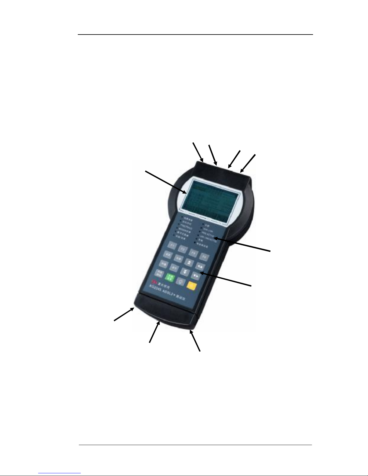
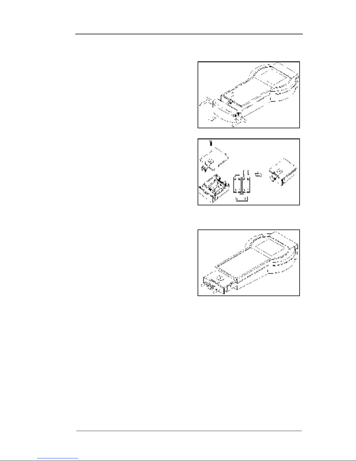
Ÿ Face panel: LCD display, LED alarm and status indicators, keyboard
Ÿ Back panel: four frangible labels and serial number label
Ÿ Front panel: ADSL interfaces connector, LAN interface connector and 12VDC input
jack
Ÿ Rear panel: End cover. Press the shrapnel to unpack the end cover, and you can see
the battery compartment and RS232 port jack.
See Fig 1 (Appearance of the tester).
Fig 1: Appearances of ADSL2+ Tester
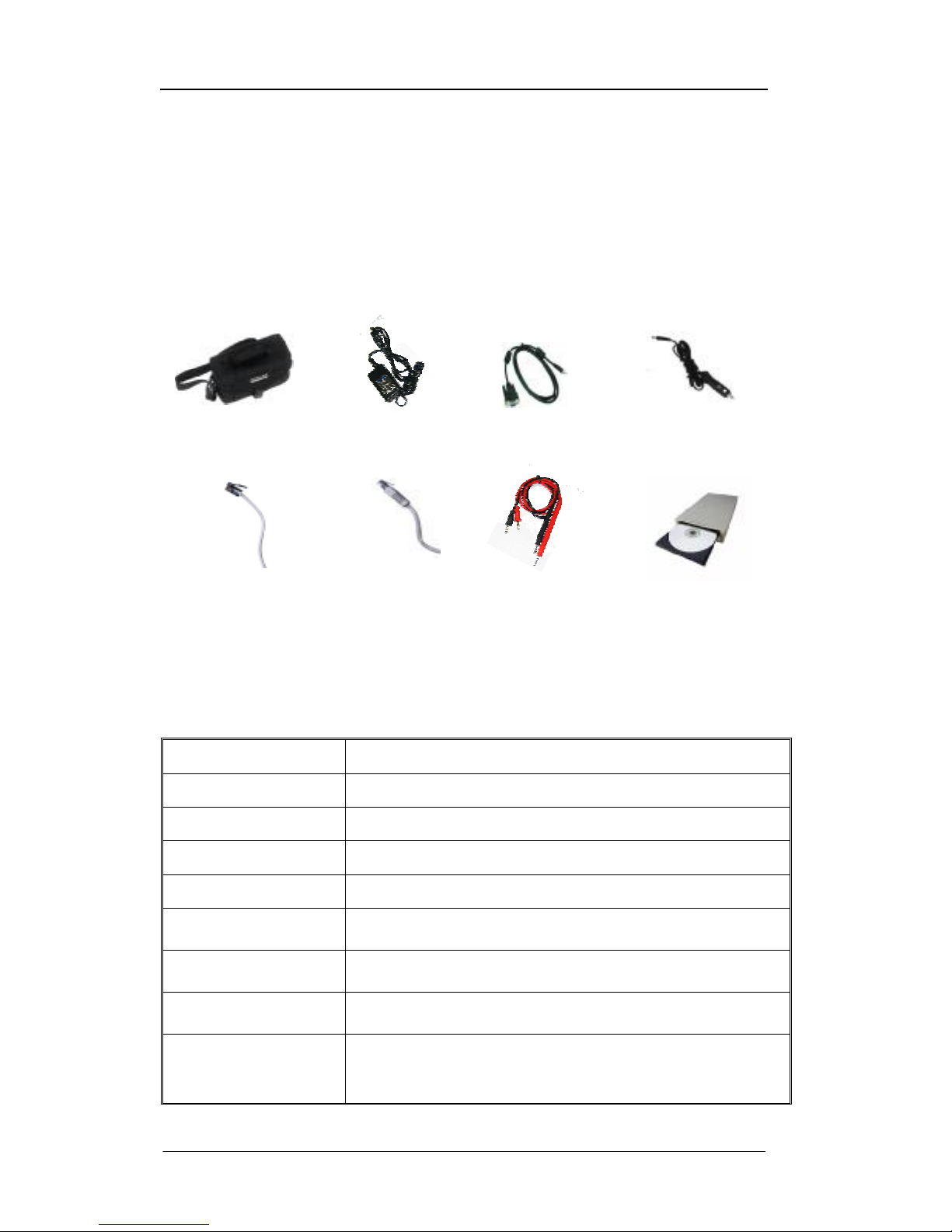
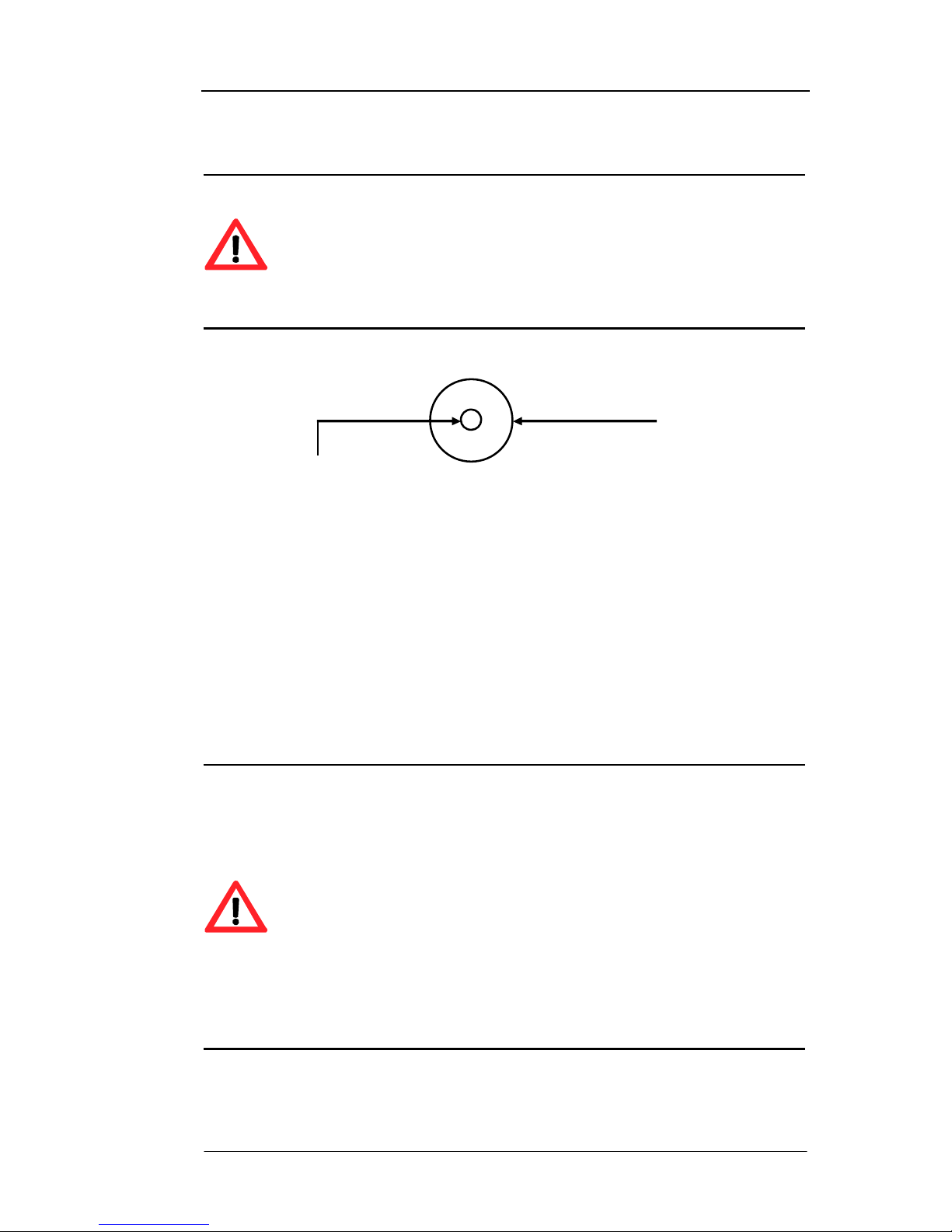
1.5.2 Accessories of ADSL2+ Tester
Ÿ Waterproof Package
Ÿ ADSL Test Cables
Ÿ LAN Test Cables
Battery
Compartment &
Rechargeable
NiMH Batteries
(Inside)
ADSL Line &
DMM Interface
LAN Interface
12VDC
Input
LCD Display
Alarm and Status Indications
Functional Keyboard
RS-232 Interface
(Inside)
DMM
Interface
End Cover
(Knock-down)
ADSL2+ Tester 1 Overview
72-0046-03A 8
Ÿ AC Power Adapter
Ÿ RS-232 Communication Cable
Ÿ Automobile Cigarette Lighter Battery Adapter Cable
Ÿ TestManagerPro Setup CD
Ÿ User’s Manual
See Fig 2 (Appearance of the tester).
Fig 2: Accessories of ADSL2+ Tester
1.6 General Specifications
The general specifications of ADSL2+ Tester are described in Table 1.
Item Descriptions
ADSL Line Connector RJ11
Ethernet Connector RJ45@100Ω
DMM Connector Φ4 Banana Connector
Line Code DMT
Downstream Rates
Supported
24Mb/s
Upstream Rate
Supported
1.2Mb/s
Transmission Distance
Supported
6.5km
Alarm and Status
Indications
LINE PARAMETER, LINE BERT, PING/TRACE, MODEM SIMULATOR,
DMM, START/STOP, ALARM, WAN LINK, WAN ACTIVE, LAN
LINK/ACTIVE, CHARGE, LOW BATTERY
Waterproof Package
AC Adapter
RS-232
Communication Cable
ADSL Test
Cables
Automobile Cigarette
Lighter Battery Adapter
TestManagerPro Setup CD
and User’s Manual
LAN Test
Cables
DMM Test
Cables

ADSL2+ Tester 1 Overview
72-0046-03A 9
Standards Supported
ITU-T G.992.1 (G.DMT), ITU-T G.992.2 (G.lite), ITU-T G.992.3
(ADSL2), RE-ADSL, ITU-T G.992.4 (Splitterless ADSL2), ITU-T
G.992.5 (ADSL2+), ITU-T G.992 Annex A, Annex B, Annex C
(FBM/DBM), ANSI T1.413 Issue 2, YDN078-1998
Encapsulation
Supported
PPP over ATM (PPPoA), PPP over Ethernet (PPPoE), RFC-1483
Bridge (BRIDGE), IP over Ethernet over ATM (MER), IP over ATM
(IPoA)
Services Supported
ATM、UBR、VBR、CBR
Serial Port
RS-232C
Rechargeable
Batteries
5×1.2V AA NiMH batteries, continuous working for 2.5 hours
Recharging Time
Embedded with fast re-charger, recharging time 1.5 hours, finish
recharging automatically when being full charged.
AC Power Adapter
Input: AC 100V-240V, 50/60Hz
Output: DC12V/1.5A
TestManagerPro
WIN98/ME/2000/NT/XP
Operating
Temperature
0°C~50°C
Humidity
5%~95% non-condensing
Dimensions
L×W×H 243mm×90/128mm×60mm
Weight
Approx. 700g
Table 1: Specifications of ADSL2+ Tester

ADSL2+ Tester 2 Getting Started
72-0046-03A 10
2. Getting Started
This chapter is intended to introduce unpacking check and attention points in summary.
2.1 General Information
2.2 Unpacking Check
2.1 General Information
In order to safely transport, ADSL2+ Tester is packaged by carton. And all the accessories
including User’s Manual, CD, Quality Certificate Card, Maintenance Card are placed in the
waterproof package.
2.2 Unpacking Check
Please check when receiving the product:
• If the packing carton is impaired and if the appearance of the product is impaired.
• If the instrument and all its accessories are available.
The standard configuration list of ADSL2+ Tester is shown in Table 2.
Item Qua.
Item Qua.
ADSL2+ Tester 1 TestManagerPro Setup CD 1
LAN Test Cable (Direct, Black) 1
LAN Test Cable (Intercross, Grey) 1
Automobile Cigarette Lighter Battery
Adapter Cable
1
ADSL Test Cable (RJ-11) 1
Waterproof Package
1
ADSL Test Cable (Clamp) 1
User’s Manual
1
DMM Test Cable 2 Maintenance card 1
RS232 Communication Cable 1
Quality Certificate Card
1
AC Power Adapter 1
Packing List
1
Table 2: Standard configuration list of ADSL2+ Tester
Caution:
Please check the configurations of instrument item by item according to the
packing list. Please contact your vendor if anything is unavailable.
Please fill in the product maintenance card carefully and take good care of it.
If necessary, keep the packing materials in case they will be needed some
time.

ADSL2+ Tester 3 Manipulation
72-0046-03A 11
3. Manipulation
This chapter mainly introduces the alarm LED indicators, functional keyboard, the
preparations for operation, brief menu introduction, communication with PC, charge, power
management and safety precaution in summary.
3.1 LED Indicators
3.2 Functional Keyboard
3.3 Preparations for Operation
3.4 Brief Menu Introduction
3.5 Communicate with PC
3.6 Rechargeable Batteries and Charge
3.7 Power Management
3.8 Safety Precaution
3.1 LED Indicators
ADSL2+ Tester has 10 alarm and 2 status LED indicators. The red LEDs flash to indicate that
any error or alarm conditions which occurred currently. All the indicators will be described as
below.
3.1.1 Status LEDs
• “LINE PARAMETER” functional LED
If you select “Line Parameter” function to test, this LED will be lit green. This LED
mainly indicates that the current selected test function.
• “LINE BERT” functional LED
If you select “Line BERT” function to test, this LED will be lit green. This LED mainly
indicates that the current selected test function.
• “PING/TRACE” functional LED
If you select “PING” or “Trace” function to test, this LED will be lit green. This LED
mainly indicates that the current selected test function.
• “MODEM SIMULATOR” functional LED
If you select “MODEM Simulator” function to test, this LED will be lit green. This
LED mainly indicates that the current selected test function.
• “DMM” functional LED
If you select “DMM” function to test, this LED will be lit green. This LED mainly
indicates that the current selected test function.

ADSL2+ Tester 3 Manipulation
72-0046-03A 12
• “START/STOP” status LED
To start or stop the test can be switched by pressing “Start/Stop” key. And in
“Start” status, LED is lit green continuously. In “Stop” status, LED will be turned off.
• “ WAN LINK” status LED
This LED indicates whether or not WAN link is normally connected.
Light: It indicates that the tester has linked to ATU-C.
Flash slowly: It indicates that the tester is trying to build link to ATU-C.
Flash quickly: It indicates that the tester is handshaking with ATU-C.
Wink: It indicates that the tester has unlinked to ATU-C.
• “WAN ACTIVE” status LED
This LED indicates a WAN active state.
Flash: It indicates that the tester is transmitting data to ATU-C.
Wink: It indicates that no data transitions between the tester and ATU-C, or the
ADSL line is interrupted.
• “LAN LINK/ACT” status LED
This LED indicates a LAN link and active state.
Light: It indicates that the tester has linked to LAN, and there has no data
transitions between the tester and LAN.
Flash: It indicates that there are data transitions between the tester and LAN.
Wink: It indicates that the tester unlinks to LAN
• “CHARGE” status LED
The LED lights orange when the battery is being charged. XG2040 embeds
rechargeable batteries and smart fast charger circuit. And LED will be turned off
after fully charged.
3.1.2 Alarm Indicators
• “ALARM” LED
Light: When this LED is lit red, it indicates that the tester links to ATU-C
unsuccessfully or other errors happened such as the parameters
breakthrough the thresholds. Otherwise, this LED will be turned off.
• “LOW BATTERY” LED
This LED lights red when built-in NiMH battery’s voltage has dropped to a low level
without external power supply. The LED will be turned off when the battery is
charged by the external power supply. This LED with red indicates that the tester will

ADSL2+ Tester 3 Manipulation
72-0046-03A 13
automatically shut down soon.
3.2 Functional Keyboard
ADSL2+ Tester has 16 functional keys at the front panel, including main functional keys,
softkeys, cursor keys, page keys, a backlight key, a power switch key, a start/stop key, a
auto test key, etc. The arrangement of functional keys and names of keys from left to right
are as shown in Fig 3.
These functional keys are described as in Table 3.
`
Fig 3: Functional keyboard
Caution:
The key-stroke beep can be set as “ON” or “OFF” in “Others” menu. When
the key-stroke beep is set as “ON”, the right key-stroke leads to one beep
while wrong or invalid key-stroke leads to two beeps. As prompt, there will be
relevant hint information in LCD display at the same time.
Key Name Description
Softkeys
Identified as “F1” to “F4”, used to select the parameter or activity in
corresponding highlight place at the bottom of LCD. Each LCD display
defines one or more functions of these softkeys.
“Setting”
Matched with the “Settings” menu. When this key is pressed, LCD display
switches to the “Settings” menu.
“Result”
Matched with the “Results” menu. When this key is pressed, LCD display
switches to the “Results” menu.
“Storage”
Matched with the “Storages” menu. When this key is pressed, LCD
display switches to the “Storages” menu.
“Other”
Matched with the “Others” menu. When this key is pressed, LCD display
switches to the “Others” menu.
F1
F2 F4 F3
SETTIN
G
RESULT
STORAGE
OTHER
AUTO
TEST
START
STOP
Softkeys: “F1”, “F2”, “F3”, “F4”
“Setting”, “Result”, “PgUp”, “Cursor
moveable left and up” key
“Storage”, “Other”, “PgDn”, “Cursor
moveable right and down” key
“
Auto Test
”, “Start/Stop”,
“Backlight”, “Power” key

ADSL2+ Tester 3 Manipulation
72-0046-03A 14
“Auto Test”
In “Line Parameter” test mode, press this key to auto start the test with
the “AUTO” line standard. And the displays of LCD will switch to “Result”
menu directly. In “DMM” test mode, press this key to auto detect and test
the loop line.
“Start/Stop”
Manually control the start or stop activity of the test. Press it to start the
test and press it again to stop the test.
“Page Up”
When page number appears in the display menu (Like “P: 2/4”, indicates
that display menu has 4 pages in all and is on page 2 currently), press this
key to go page up.
“Page Down”
When page number appears in the display menu (Like “P: 2/4”, indicates
that display menu has 4 pages in all and is on page 2 currently), press this
key to go page down.
“Cursor
Moveable Left
and Up”
Move the cursor upward and leftward and the cursor can reach the position
with “[ ]”.
“Cursor
Moveable Right
and Down”
Move the cursor downward and rightward and the cursor can reach the
position with “[ ]”.
“Backlight” Turn on or off the LCD backlight according to the light condition.
“Power” Switch on or off the instrument.
Table 3: Functional keys descriptions
Caution:
Pressing “AUTO TEST” key can auto start the ADSL line parameter test in any
operating menu of the tester, except for “DMM” testing mode. The displays
will be directly switched into the result menu of “Line Parameter” and the
“Start/Stop” LED will be turned on. In this condition, the line standard will be
automatically set as “AUTO”.
Caution:
The key-stroke beep can be set as “ON” or “OFF” in “Others” menu. When
the key-stroke beep is set as “ON”, the right key-stroke leads to one beep
while wrong or invalid key-stroke leads to two beeps. As prompt, there will be
relevant hint information in LCD display at the same time.

ADSL2+ Tester 3 Manipulation
72-0046-03A 15
3.3 Preparations for Operation
n After unpacking, check if the carton or the appearance of the tester is damaged or
not.
n Check if the tester and its accessories are integrated or not.
n Plug the AC adapter into an appropriate AC wall outlet. And connect the tester with
AC power adapter cable, check if the “Charge” status LED will be lit.
n Press “Power” key to switch on the tester, LCD screen will display the LOGO of
manufacturer and the embedded software version. After 3 seconds, buzzer will beep
once, the software will be loaded completely and the tester is initializing for about 20
seconds.
n Select the function what you want to test, and link the test cable between the tester
and the line under test.
After making above steps, you can configure settings and make the
measurements.
3.4 Brief Menu Introduction
The operating menus of ADSL2+ Tester include “Settings”, “Results”, “Storages” and
“Others” menu, matched with the “Setting”, “Result”, “Storage” and “Other” functional
keys respectively. These four menus can be switched from one to another at any time by
pressing these four functional keys.
“PgUp” and “PgDn” keys provide page up and down functions, “Cursor Moveable Right
and Down” and “Cursor Moveable left and Up” keys provide cursor movement functions,
“F1”, “F2”, “F3”, “F4” softkeys are used to select the parameter or actions at the bottom of
LCD which matched with the place highlighted by the cursor.
In each of display areas the field currently able to be changed is marked by a “Highlight
Cursor”. The menu of selection available for the active field is displayed on softkeys on the
bottom of the display. The choice from the menu is made using the keys situated
immediately below the display. The highlighted cursor is moved around the display using
page and cursor keys. When a highlighted field has more than 5 choices a softkey labeled >>
is provided. When >> is chosen the remainder of the menu is revealed.
n “Settings” Menu
Press the “Setting” key to enter into the settings menu. All the information that related to
the chosen test function and the setting of the parameters are provided in the “Settings”
menu. Press the “Cursor Moveable Right and Down” and “Cursor Moveable left and
Up” keys to move the cursor, press the “F1”, “F2”, “F3” and “F4” softkeys to select the
corresponding parameters. In case page number appears in the LCD menu, such as “P: 1/2”,
turn page by pressing the “PgUp” or “PgDn” key. Press the “Start/Stop” key to start the

ADSL2+ Tester 3 Manipulation
72-0046-03A 16
test after all the settings have already been configured completely.
n “Results” menu
Press the “Result” key to switch to the results menu. All the information that related to the
result statistics, performance analysis and measurement readings are provided in the
“Results” menu. “F1”, “F2”, “F3”, “F4” softkeys are used to select various types of result
analysis and statistics. In case page number appears in the menu, such as “P: 1/2”, then the
page can be turned by pressing the “PgUp” or “PgDn” key.
n “Storages” menu
Press the “Storage” key to switch to the storages menu. Press the “Cursor Moveable
Right and Down” and “Cursor Moveable left and Up” keys to select storage’s name,
press the “F1”, “F2”, “F3”, “F4” softkeys to view, delete, lock, unlock, rename and do other
actions to the settings and results of the stored record. In the stored results, the settings
and results information of a test are available.
n “Others” menu
Press the “Other” key to switch to the auxiliary information menus. In “Others” menu, it
provides the settings and examination to the auxiliary functions and instrument. Following
auxiliary information menus can be accessed by pressing the “F1”, “F2”, “F3” and “F4”
softkeys, including Miscellaneous, Power Management, Time & Date, RS232 Port,
Keyboard Test, Self-test, Tester Information.
Due to the working circumstances, the status prompt information line which is
above the highlighted field provides operating status of the instrument.
The upper right corner of LCD “Ð ” indicates that the parameters can be
modified, “Ï” indicates that the instrument is currently doing one test,
softkeys are under the lock status, and the highlighted settings can not be
modified.
“
Ð
” in the “Storages” menu indicates that there still has storage space to
save more records in the instrument. “Ï” indicates that no saving space is
available, some records must be deleted firstly to save the new records. “Ð ”
and “Ï” following each saved record respectively indicate that the record is
under locked or unlocked status.
3.5 Communication with PC
This tester supports communication with PC via RS232C interface by TestManagerPro
software. And TestManagerPro can do two jobs: one is to upload the test results stored in
the instrument to PC for further processing including filing, printing and analyzing, and the
other is to upgrade the embedded software via PC to protect your investment.
3.5.1 Communication Steps
ADSL2+ Tester 3 Manipulation
72-0046-03A 17
• Switch off the tester firstly.
• Open the end cover of the tester.
• Connect RS232 interface of the tester to PC serial port with RS232 communication
cable (supplied).
• Switch on the tester.
• Set RS232 port state to ON in “Others” menu.
• Run the TestManagerPro software on PC, click “Select” button to choose the tester’s
type and click “Connect” button. After the successful connection, the user can upload,
view, analyze, delete, print test results in the form of report and do other operations.
• Switch off the tester after communication with PC.
• Pull out the RS232 communication cable.
Warning:
Be sure not to plug and unplug the communication cable alive when
connecting PC serial interface to the tester using the serial communication
cable, and be sure to ground or use ESD wrist strip. Plug and unplug the
communication cable alive may result in damage to PC or the serial interface
of the tester.
3.5.2 Upgrading the Embedded Software
Manufacturer will launch the latest version embedded software and host software
TestManagerPro in the website of our company for the users to download. Make sure to
visit our website frequently to ensure you will always get the software of latest version.
For the software upgrading method, please refer to the relevant part of “Communication
with PC” and follow instructions of the TestManagerPro.
Caution:
When performing the embedded software upgrading, in order to prevent the
instrument powered off caused by the battery exhausted, it is strongly
recommended to use external AC power supply to power the tester.
3.6 Rechargeable Batteries and Charge
The rechargeable batteries will typically power the tester for more than 2.5 hours with the
backlight and testing mode selected. The tester uses 5 high-performance 2300mAH Nickel
Metal Hydride (NiMH) rechargeable batteries placed in the battery case that may not be fully
charged when the user receives the tester. Whatever the state of charge, use the tester until
the battery is completed exhausted before giving it its first charge. This will ensure better
accuracy from the battery charge indicator.
ADSL2+ Tester 3 Manipulation
72-0046-03A 18
Warning:
Do not change the battery model!
Do not use old and new rechargeable batteries together!
Do not use non-recharge battery, in case that may cause the battery
explosion or other danger.
Caution:
When the battery supplied for this tester has been used expiring the charging
life or are impaired, they should be dealt with control. If dealt with general
waste processing system detained in the tester, they will harm the tester. The
waste batteries contain Nickel-Metal Hydride and must be recycled or
disposed of properly at special recycling station or hazardous waste collection
center.
n Replacement of Rechargeable Battery
A new rechargeable battery can be charged and discharged for about 800~1000 times
before it can not be used any more. Normally the fully charged batteries could support the
tester continuous 2.5 hours working depending upon the test settings. So when the
operating duration of the battery is apparently reduced, the batteries should be replaced.
It is strong recommended that the rechargeable batteries should be replaced
every one or two years!
The NiHM recharge battery may become invalid after no used for a long time.
It can only be reused after reactivation.
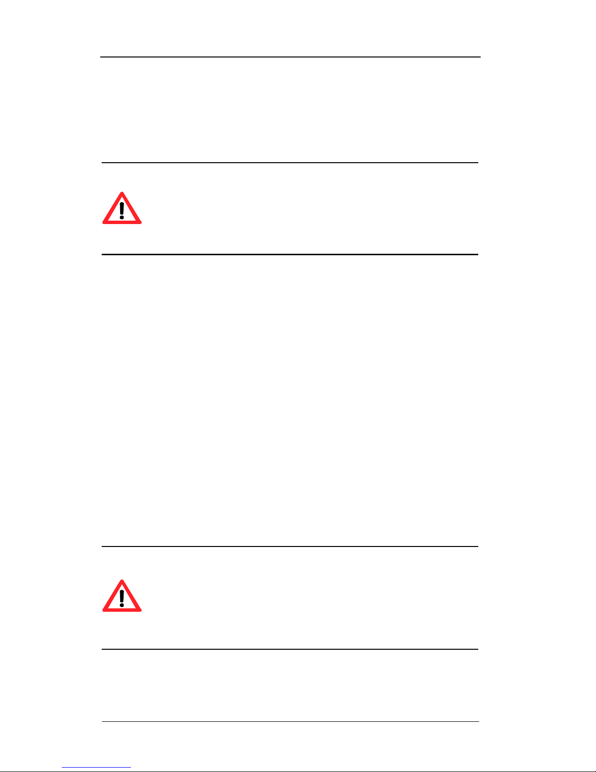
n Method of Battery Replacement
Ensure the tester is switched off firstly. And open the end cover of the tester and slightly
press the battery compartment lock card downward, the battery case will pop out. Extract
the battery compartment and unscrew the screws on the top of the case to open and replace
new batteries (Be careful of not mistaking the polarity of the battery). When the battery
compartment has been loaded again, slip it back into the battery case frame and push the
battery compartment inside (Put your fingers upon the case rather than the battery case
lock card), the battery case is installed well while a “KaTa” sound is heard. The battery
replacement is completed when the end cover of the tester is mounted again.
Warning:
When installing the battery compartment back to the battery case frame,
please ensure not to push overexerted, which if not will result in impairing the
battery case frame or making the battery shrapnel damaged!
ADSL2+ Tester 3 Manipulation
72-0046-03A 19
The battery replacement should be strictly conformed to the below instructions.
Ø Switched off the tester firstly. Press A
and B simultaneously with your fingers
and pull the end cover of the tester. Then
press the battery compartment lock card
C downward slightly and take out the
battery case.
Ø Unscrew the screws on the top of the
case to open the cover of the battery
case.
Ø Replace the new batteries according to
the polarity indications which are printed
in bottom of the battery case.
Ø Install the cover back and re-screw the
screws tightly.
Ø Slip the battery case back into the
battery case frame and put your fingers
upon D and E to push the battery
compartment inside. The battery case is
well installed while a “KaTa” sound is
heard. The battery replacement is
completed when the end cover of the
tester is mounted again.
n Charging the Battery
To recharge the battery, plug in the charger using an appropriate adapter (supplied).
Normally the battery will be fully charged after 2.5 hours. In exceptional circumstances
where the battery may have become deeply discharged, a charge time of 24 hours may be
required. Note that the tester can be used while the battery is charging. During rapid
charging, the “Charge” LED indicator turns on. When the rapid charging is completed,
charging automatically turns into a trickle charge, the “Charge” indicator turns off. The
tester certainly can be charged when it is powered off. The charging indicator can give the
right display.
In addition, the battery can be recharged with the automobile charger, at this time an
automobile cigarette lighter adapter cable is needed.
C
D E A B

ADSL2+ Tester 3 Manipulation
72-0046-03A 20
n “ Low Battery” Indication
When being powered by the battery, this tester can give the early alarm to low battery
voltage and the “Low Battery” indicator turns on. After being used for a couple of hours,
the battery voltage continues to drop to a low level, and the tester will automatically
perform protective shutdown. When the “Low Battery” indicator turns on, the external
power supply is needed to support the tester working while the battery is charging.
3.7 Power Management
This tester provides automatic power-off function. When the tester is not under test-started
status and there is no keystroke in 5 minutes, this tester will be turned off automatically.
This function can effectively prevent the tester from being accidentally turned on and the
battery from being exhausted during the transport. This function can be set to ON or OFF in
“Others” menu.
The LCD backlight can be turned on by pressing the “Backlight” key, and be automatically
turned off in 30 seconds. This function can be set to ON or OFF in “Others” menu. When set
as OFF, press the “Backlight” key to turn on the backlight, and press the “Backlight” key
again to turn off the backlight.
3.8 Safety Precautions
The following general safety precautions must be observed during all phases of operation,
service, and repair of this instrument. Failure to comply with these precautions or with
specific warnings elsewhere in this manual violates safety standards of design, manufacture,
and intended use of the instrument. The manufacturing company assumes no liability for
the customers’ failure to comply with these requirements.
Warning:
Do not operate damaged equipment: Whatever it is possible that the safety
protection features built into this product have been impaired, either through
physical damage, excessive moisture, or any other reason, remove power and
do not use the product until safe operation can be verified by service-trained
personnel. If necessary, return the product to your vendor and service office
for service and repair to ensure the safety features are maintained.
3.8.1 External Power Requirements
Please use the supplied AC adapter when operating with the instrument or charging the
battery. The supplied AC power adapter requires a power source of 100V to 240V AC at a
frequency between 50Hz and 60Hz (nominal).
AC Input: 100V ~ 240V, 50/60 Hz, Max 0.45A.
The AC adapter will output a DC power of 12V to the instrument.
ADSL2+ Tester 3 Manipulation
72-0046-03A 21
DC Output: 12V, Max 1500mA.
Warning:
Do not use other AC power adapter to provide power supply.
This instrument has an external power supply which has an autoranging line
voltage input. Ensure the line supply is within the specified range.
The supplied standard AC power adapter should be only used indoor.
DC Connector Polarity:
3.8.2 Battery Power Requirements
The battery power requirements should be strictly conformed by the instructions
described in Section 2.2.2.
In the exceptional circumstances, the operator can purchase general non-rechargeable
batteries to substitute rechargeable batteries to supply the power. When replacing the
built-in batteries, the battery compartment should be unfolded firstly. Then take out the
rechargeable batteries replacing by non-rechargeable batteries, plug the battery
compartment frame into the tail of the instrument.
Warning:
It is strongly recommended that do not use the non-rechargeable battery
unless in the urgent circumstances.
Do not recharge the batteries with the external AC power adapter when using
non-rechargeable battery to provide a power, which may result in explosion of
the battery.
Do not leave the non-rechargeable batteries in the battery compartment for a
long time after the non-rechargeable batteries have exhausted absolutely.
Please replace the non-rechargeable batteries with the rechargeable batteries
as soon as possible to avoid the explosion by mistaking charged.
3.8.3 Operating Environment
This instrument is designed for Indoor use only.
+VE
-VE
ADSL2+ Tester 3 Manipulation
72-0046-03A 22
This instrument may be operated in environments within the following limits:
Temperature: 0℃ ~ +40℃
Altitude: Up to 3050m (10,000 feet)
Humidity: 5% ~ 90%, non-condensing
Warning:
This instrument is designed for Indoor use only.
Do not operate the product in an explosive atmosphere or in the presence of
flammable gasses or fumes.
3.8.4 Operation Requirements
The network connectors are located at the top of the instrument. Before connecting, note
the Warning and Caution information given. The instrument contains components
sensitive to electrostatic discharge. To prevent component damage, carefully follow the
handling precautions presented below.
The smallest static voltage most people can feel is about 3500 volts. It takes less than one
tenth of that (about 300 volts) to destroy or severely damage static sensitive circuits.
Often, static damage does not immediately cause a malfunction but significantly reduce
the component’s life. Adhering to the following precautions will reduce the risk of static
discharge damage.
• Before handling the instrument, select a work area where potential static sources are
minimized. Avoid working in carpeted areas and non-conductive chairs. Keep body
movement to a minimum. We recommend that you use a controlled static
workstation.
• Handling the instrument by its cover. Avoid touching any components or edge
connectors.
Warning:
When connecting or disconnecting, ensure that you are grounded to bring you
and the instrument to the same static potential.
Do not connect this instrument to any signal cable carrying a hazardous
voltage.
3.8.5 Storage and Shipment Requirements
The instrument may be stored or shipped in environments within the following limits:
 Loading...