

Page 1

Pixie-32
User Manual
Version 0.2
July, 2018
Software Revision: 3.5.0
XIA LLC
31057 Genstar Rd
Hayward, CA 94544 USA
Email: support@xia.com
Tel: (510) 401-5760; Fax: (510) 401-5761
http://www.xia.com/
Information furnished by XIA LLC is believed to be accurate and reliable. However, no responsibility is
assumed by XIA for its use, or for any infringements of patents or other rights of third parties which may
result from its use. No license is granted by implication or otherwise under any patent or patent rights of
XIA. XIA reserves the right to change hardware or software specifications at any time without notice.
Page 2

Pixie-32 User Manual Version 0.2
Manual Convention 5
Introduction 5
Hardware Setup 5
Software Installation 5
Getting Started 7
Start Application 7
Configure tab 8
[Boot] 9
[Configure] 9
[Oscilloscope] 9
[Adjust Offsets] 10
Acquire tab 10
[Start] 10
[Stop] 11
[Statistics] 12
[Analysis] 12
Appendix 16
Initialization file format 16
Configuration file format 16
List-mode data format 19
Statistics file format 20
API functions 21
API Function: P32_GetAPIVersion 21
API Function: P32_SysConfig 22
API Function: Pixie_Boot_System 22
API Function: Pixie_Acquire_Data 23
API Function: PIXIE500E_GetNumberModules 25
API Function: PIXIE500E_GetModuleSerialNumber 25
© 2017 XIA LLC 2
Page 3

Pixie-32 User Manual Version 0.2
Warranty Statement
XIA LLC warrants that this product will be free from defects in materials and
workmanship for a period of one (1) year from the date of shipment. If any such product
proves defective during this warranty period, XIA LLC, at its option, will either repair the
defective products without charge for parts and labor, or will provide a replacement in
exchange for the defective product.
In order to obtain service under this warranty, Customer must notify XIA LLC of the
defect before the expiration of the warranty period and make suitable arrangements for
the performance of the service.
This warranty shall not apply to any defect, failure or damage caused by improper uses or
inadequate care. XIA LLC shall not be obligated to furnish service under this warranty a)
to repair damage resulting from attempts by personnel other than XIA LLC
representatives to repair or service the product; or b) to repair damage resulting from
improper use or connection to incompatible equipment.
THIS WARRANTY IS GIVEN BY XIA LLC WITH RESPECT TO THIS PRODUCT
IN LIEU OF ANY OTHER WARRANTIES, EXPRESSED OR IMPLIED. XIA LLC
AND ITS VENDORS DISCLAIM ANY IMPLIED WARRANTIES OF
MERCHANTABILITY OR FITNESS FOR A PARTICULAR PURPOSE. XIA’S
RESPONSIBILITY TO REPAIR OR REPLACE DEFECTIVE PRODUCTS IS THE
SOLE AND EXCLUSIVE REMEDY PROVIDED TO THE CUSTOMER FOR
BREACH OF THIS WARRANTY. XIA LLC AND ITS VENDORS WILL NOT BE
LIABLE FOR ANY INDIRECT, SPECIAL, INCIDENTAL, OR CONSEQUENTIAL
DAMAGES IRRESPECTIVE OF WHETHER XIA LLC OR THE VENDOR HAS
ADVANCE NOTICE OF THE POSSIBILITY OF SUCH DAMAGES.
1.1 Contact Information:
XIA LLC
31057 Genstar Rd.
Hayward, CA 94544 USA
Telephone: (510) 401-5760
Downloads: http://support.xia.com
Hardware Support: support@xia.com
Software Support: support@xia.com
© 2017 XIA LLC 3
Page 4

Pixie-32 User Manual Version 0.2
2 Manual Convention
The following conventions are used throughout this manual
Convention
Description
Example
Bold
Bold text denotes items that
you must select or click on in
the software, such as menu
items, and dialog box
options.
...click on the MCA tab.
[Bold]
Bold text within [ ] denotes a
command button.
[Start Run] indicates the command button
labeled Start Run.
monospace
Items in this font denote text
or characters that you enter
from the keyboard, sections
of code, file contents, and
syntax examples.
Setup.exe refers to a file called “setup.exe”
on the host computer.
“window”
Text in quotation refers to
window titles, and quotations
from other sources
“Options” indicates the window accessed via
Tools»Options.
Italics
Italic text denotes a new term
being introduced , or simply
emphasis
peaking time refers to the length of the slow
filter.
...it is important first to set the energy filter Gap
so that SLOWGAP to at least one unit greater
than the preamplifier risetime...
© 2017 XIA LLC 4
Page 5

Pixie-32 User Manual Version 0.2
3 Introduction
3.1 Hardware Setup
Place the Pixie-32 modules into any peripheral PXIe or PXIe/PXI hybrid slot with the
chassis still powered down, then power up the chassis (Pixie-32 modules are not hot
swappable). If using a remote controller, be sure to boot the host computer after powering
up the chassis.
3.2 Software Installation
Currently API library (Pixie32.dll) is distributed as a pre-built DLL for 64-bit Windows.
When the host computer is powered up the first time after installing the controller and
Pixie-32 modules in the chassis, it will detect new hardware and try to find drivers for it.
(A Pixie-32 module will be detected as a new device every time it is installed in a new
slot.) While there is no required order of installation of the driver software, the following
sequence is recommended (users with embedded host computer skip to step 4):
1. If you have a remote controller, first install the driver software for the controller
itself. Otherwise, skip to step 4.
Unless directed otherwise by the manufacturer of the controller, this can be done
with or without the controller and Pixie-32 modules installed in the host computer
and/or chassis. If the modules are installed, ignore attempts by Windows to install
drivers until step 7.
NI controllers come with a multi-CD package called “Device Driver Reference CD”.
For simplicity it is recommended to install the software on these CDs in the default
configuration.
2. Unless already installed, power down the host computer, install the controller in
both the host computer and chassis, and power up the system again (chassis first).
3. Windows will detect new hardware (the controller) and should find the drivers
automatically. Verify in Windows device manager that the controller is properly
installed and has no “resource conflicts”.
4. Unless already installed, power down the host computer and install the Pixie-32
modules in the chassis. Then power up the system again (chassis first). Ignore
attempts by Windows to install drivers until step 7.
5. Install the Pixie-32 software provided by XIA.
(for version X.Y.Z)
Pixie-32_X.Y.Z_setup.exe
Run the setup program and follow the instructions shown on the screen to install the
software to the default folder selected by the installation program, or to a custom
folder. Driver installation is rather lengthy (the PC may pause for extended periods
of time) and may require acknowledgment of unsigned drivers. The installation
© 2017 XIA LLC 5
Page 6
Pixie-32 User Manual Version 0.2
folder will contain 7 subfolders (Sample, Configuration, Firmware, Drivers, Doc,
DSP, PixieCLib). “Sample” is default location for starting the viewer.
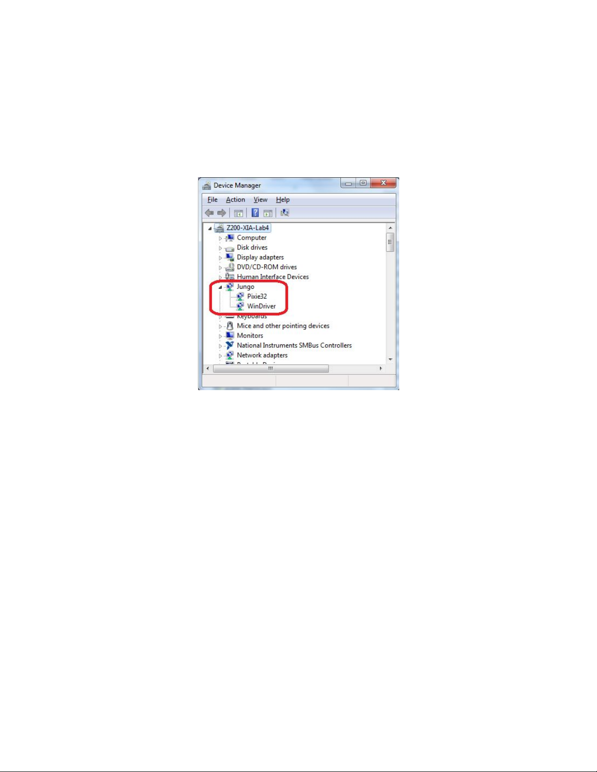
6. Windows will detect new hardware (the Pixie-32 modules) and should find the
drivers automatically. If not, direct it to the “Drivers” directory in the Pixie-32
software distribution installed in step 5. Verify in Windows device manager that the
modules are properly installed as “Pixie32” (along with WinDriver) under Jungo
devices and have no “resource conflicts”.
7. If kernel driver (WinDriver) and device driver (Pixie32) need to be installed
manually, change in “Drivers/amd64” directory (for 64-bit system), and execute
a. wdreg.exe -inf windrvr6.inf install
b. wdreg.exe -inf Pixie32.inf install
8. Display and analysis GUI needs Python and wxPython to be installed:
a. Install Python-2.7 for 64-bit architecture
b. Install wxPython-3.0 for 64-bit architecture
c. Install matplotlib/numpy modules for Python. On console, execute:
i. python -m pip install -U pip setuptools
ii. python -m pip install matplotlib
© 2017 XIA LLC 6
Page 7

Pixie-32 User Manual Version 0.2
Getting Started
Start Application
The installation script should have placed the following files in the Sample sub-folder: Pixie32.dll, Python
files (wx_pixie32.py, pixie32.py, p32_globals.py, event_frame.py, spectrum_frame.py, stats_frame.py,
oscilloscope_frame.py), initialization file (default p32.ini), parser.exe. The initialization file contains
locations of the FPGA firmware file (p32_firmware_r*.bin, placed in Firmware folder), and of
configuration files for each module (FipRegs_m00.txt in Configuration folder).
The initialization file must have the list of serial numbers, matching those of modules installed in chassis.
To start the Pixie-32 Viewer, open terminal, change into directory containing Python scripts and
Pixie32.dll (usually Sample folder), and execute:
python wx_pixie32.py p32.ini
Note that some operations can be applied to all modules at one (boot, configure, run start, run stop, adjust
offsets), if “All modules” checkbox by the module list is marked. Same operations can be performed on a
single module (checkbox is not marked). Some operations (oscilloscope, reading live statistics) only apply
to one module, selected from the module list. Some operations deal with post-processing data (event
display, reading offline statistics read and parse data from files), and do not depend on module selected in
the module list.
The viewer can be started in offline mode
python wx_pixie32.py --offline p32.ini
This can be used for analysis of already collected data.
Internally modules are addressed by 0-based enumeration, which is normally used by log printouts.
Console window is primary output of error, status, and debug messages from API function calls, and the
GUI. API messages are also recorded in PIXIEmsg.txt file. Verbosity of the output is set via initialization
file.
© 2017 XIA LLC 7
Page 8

Pixie-32 User Manual Version 0.2
Configure tab
Prior to performing any operations with the instrument, FPGA must be booted with correct firmware file,
and internal FPGA registers initialized with user-provided parameters. Locations of firmware and
© 2017 XIA LLC 8
Page 9

Pixie-32 User Manual Version 0.2
configuration files are read from the initialization file, and displayed above “Configure” button box.
Actions of clicking buttons are described below.
[Boot]
Load the FPGA firmware to the instrument. After successful booting, the front panel LED will start
blinking. Booting must be performed before any other operations after power up, and every time new
firmware file needs to be loaded. Not necessary in offline mode. Not needed if instrument has been
already booted (just restarting the viewer software).
[Configure]
Read in configuration file, check parameter values, apply them to the hardware. Needed every time after
re-booting FPGA (cold start, or after loading firmware), as well as when parameters have been changed in
the configuration file and need to be applied. Non necessary in offline mode, or if the instrument has been
already booted and configured (just after restarting the viewer software).
[Oscilloscope]
Can be used to check signal quality and DC offsets. Not available during data acquisition.
© 2017 XIA LLC 9
Page 10

Pixie-32 User Manual Version 0.2
[Adjust Offsets]
Can be used to automatically set baselines to 10% of ADC range. The values of DCOffset parameter for
each are written to file adjust_offsets_m##.txt (where ## is module number), so they can easily be pasted
into configuration file. Not available during data acquisition.
Acquire tab
Once device is booted and configured, it is ready to acquire list-mode data. Data stream consists of header
words and optional captured trace samples. Event is recorded if it passes threshold and no pile-up
conditions. Header structure is described in “List-mode data format” below. The configuration parameters
defining event recording are:
● FastThreshold: trigger threshold, must be adjusted, so the events are recorded with reasonable
dead time.
● TraceMode: when set to 3, trace is captured. With other values, only event headers are recorded.
● QDCEnable: when set to 1, QDC sums (of lengths defined by QDC#Len) are recorded in words
5--8 of event headers. Otherwise (parameter is set to 0), the event header consists of 4 words.
● TraceLength: size of recorded trace in 20-ns samples.
● ExtTrigEnable: when set to 1, external trigger must be provided to capture events.
● PSDEna: when set to 1, PSA trigger parameters must be tuned to trigger properly.
As data is streamed in 2MB buffers to the host, where it is recorded in file, defined by name in the main
panel (File Name: text input box), with extension .b## (## is module number).
It is possible to start/stop run simultaneously for all modules, or just the one selected in the module list.
[Start]
© 2017 XIA LLC 10
Page 11

Pixie-32 User Manual Version 0.2
Prepare for the run: open output files, initialize DMA and interrupts, and start data acquisition. In
free-running mode, run time in seconds is displayed in Time,(s) text box. When checkbox near Time is
checked, run time is set by preset time entered in the text box, and during run is counting down.
[Stop]
Stop data acquisition, record run statistics, close output files, free DMA and interrupt resources. [Stop]
can be used in either free-running, or time-preset mode.
© 2017 XIA LLC 11
Page 12

Pixie-32 User Manual Version 0.2
[Statistics]
During active run, display statistics (live time (seconds), fast peaks (number of triggers), number of
events (number of recorded events), and calculated Input Counting Rate, Output Counting Rate, Dead
Time) for selected module, for all 32 channels. Data is recorded in <base_name>.s## file (for format
description see below). The statistics is also automatically recorded at the end of a run. Clicking
[Refresh] on the Statistics window when no run is underway, prompts to open <base_name>.s## file,
parses, and displays its contents.
[Analysis]
© 2017 XIA LLC 12
Page 13

Pixie-32 User Manual Version 0.2
[Open] button prompts to open list-mode data <base_name>.b## file. Once file is opened, it is parsed (by
parser.exe, which should be in the current directory), outputting event information into
<base_name>.b##_TS.txt file. If the binary file has already been parsed: the <base_name>.b## _TS.txt
file has been generated, the time-consuming parsing can be skipped by unchecking the checkbox close to
[Open] button (but still selecting original list-mode binary file in the file selection box).
© 2017 XIA LLC 13
Page 14

Pixie-32 User Manual Version 0.2
Information from the parsed file for the selected event is displayed in the event window, along with
recorded (if configured so) trace.
After binary file is successfully parsed, [MCA] button is enabled, and it opens window, displaying time
stamps vs event number, and energy histogram for the selected channel.
© 2017 XIA LLC 14
Page 15

Pixie-32 User Manual Version 0.2
© 2017 XIA LLC 15
Page 16

Pixie-32 User Manual Version 0.2
Appendix
Initialization file format
Typical name is p32.ini, but can be anything, the filename is provided as argument to the wx_pixie32.py
script. The file should contain at least 5 lines, without blank lines.
Description of .ini file format:
1. firmware path (.bin file). Relative or absolute path.
2. configuration file path and basename. Relative or absolute path. Configuration parameter file
names would be <basename>_m##.txt (## is module number).
3. chassis ID (0--3)
4. verbosity (0: only errors, 1: errors and boot messages, 3: errors, status, and detailed debug
messages)
5. module serial numbers
The serial number entries must be on separate lines, and match the modules installed in the chassis.
Configuration file format
Filename should be in <Configuration_base_name>_m##.txt format (## is module number.), separate file
for each module, where <Configuration_base_name> is FipRegs by default, but can be anything.
Configuration file path and base name are given in the initialization file.
Description of FPGA parameters, their meaning, allowed ranges:
Polarity: Sets the polarity of input signal
= 1, input signal has positive polarity
= 0, input signal has negative polarity
DCOffset: Sets the DC-offset voltage. Valid value range is 0 to 16383.
FastLength: Sets the rise time of the trapezoidal trigger filter (regular). Valid value range is 2
to 63.
RiseTime (regular) = FastLength * 20 ns
There is a constraint concerning the sum value of the two trigger filter
parameters: 2 <= FastLength + FastGap <= 63
FastGap: Sets the flat top of the trapezoidal trigger filter (regular). Valid value range is 0 to
61.
FlatTop (regular) = FastGap * 20 ns
© 2017 XIA LLC 16
Page 17

Pixie-32 User Manual Version 0.2
There is a constraint concerning the sum value of the two trigger filter
parameters: 2 <= FastLength + FastGap <= 63.
FastThreshold: This is the threshold used by the trapezoidal trigger filter (regular) in the FPGA.
The value relates to the trigger threshold of the trapezoidal trigger filter (regular)
through the following formula:
Trigger Threshold (regular) = FastThreshold * FastLength
Note the constraint: 1 <= Trigger Threshold (regular) <= 65535.
ShortFastLength: Sets the rise time of the trapezoidal trigger filter (short). Valid value range is 2 to
63.
RiseTime (short) = ShortFastLength * 20 ns
ShortFastGap: Sets the flat top of the trapezoidal trigger filter (short). Valid value range is 0 to
61.
FlatTop (short) = ShortFastGap * 20 ns
There is a constraint concerning the sum value of the two trigger filter
parameters: 2 <= ShortFastLength + ShortFastGap <=
63.
ShortFastThreshold: This is the threshold used by the trapezoidal trigger filter (short) in the FPGA.
The value relates to the trigger threshold of the trapezoidal trigger filter (short)
through the following formula:
Trigger Threshold (short) = ShortFastThreshold * ShortFastLength
Note the constraint: 1 <= Trigger Threshold (short) <= 65535.
SlowLength: Sets the rise time of the trapezoidal energy filter. Valid value range is 2 to 124.
RiseTime (energy) = SlowLength * 2
SlowDecimation
* 20 ns
There is a constraint concerning the sum value of the two energy filter
parameters: 5 <= SlowLength + SlowGap <= 127.
SlowGap: Sets the flat top of the trapezoidal energy filter. Valid value range is 3 to 125.
FlatTop (energy) = SlowGap * 2
SlowDecimation
* 20 ns
There is a constraint concerning the sum value of the two energy filter
parameters: 5 <= SlowLength + SlowGap <= 127.
© 2017 XIA LLC 17
Page 18

Pixie-32 User Manual Version 0.2
SlowDecimation: Sets the energy filter range, i.e., the number of ADC samples (2
SlowDecimation
) to be
averaged before entering the energy filtering logic. The currently supported
energy filer range in the FPGA includes 1, 2, 3, 4, 5, and 6.
TraceMode: Selects trace recording mode:
= 3, record traces
= other values (0, 1, 2), no trace recorded
TraceLength: Sets how many 32-bit words of 16-bit trace data to record for each event (i.e.
number of samples ADC samples is twice TraceLength)
TraceLength must be multiples of 8
Note the constraint: 16 <= TraceLength <= 2000
TraceDelay: Sets the length of pre-trigger trace data for trace capture
TraceDelay must be multiples of 8
Note the constraint: 16 <= TraceDelay <= 1016
PreampTau: Sets preamplifier exponential decay time constant, in microseconds
BLScale: The Pixie-32 measures baselines continuously and effectively extracts DC-offsets
from these measurements. The DC-offset value is needed to apply a correction to
the computed energies. To reduce the noise contribution from this correction
baseline samples are averaged in a geometric weight scheme. The averaging
depends on BLScale:
DC_avg = DC_avg + (DC - DC_avg) * 2
-BLScale
DC is the latest measurement and DC_avg is the average that is continuously
being updated. At the beginning, and at the resuming, of a run, DC_avg is
seeded with the first available DC measurement.
Valid values for BLScale are 0, 1, …, 10
FtrigoutLen: Reserved and not used
CFDDelay: Reserved and not used
CFDScale: Reserved and not used
CFDMode: Choose leading edge trigger or CFD trigger:
= 0, use leading edge trigger
= 1, not supported
© 2017 XIA LLC 18
Page 19

Pixie-32 User Manual Version 0.2
ExtTrigEnable: Enable or disable external trigger:
= 1, use external trigger
= 0, do not use external trigger
TrigMode: Specify the trigger mode:
= 0, regular trigger mode
= 1, not supported
= 2, not supported
= 3, not supported
QDCEnable: Enable or disable QDC sums recording:
= 1, enable QDC sums recording
= 0, disable QDC sums recording
QDC0Len: Sets the length of the first QDC sum
Note the constraint: 1<= QDC0Len <= 32767
QDC1Len: Sets the length of the second QDC sum
Note the constraint: 1<= QDC1Len <= 32767
QDC2Len: Sets the length of the third QDC sum
Note the constraint: 1<= QDC2Len <= 32767
QDC3Len: Sets the length of the fourth QDC sum
Note the constraint: 1<= QDC3Len <= 32767
FFDelay: Sets the delay on the ADC data between the short fast filter and the regular fast
filter (ADC data for the short fast filter is later).
Note the constraint: 0 <= FFDelay <= 63.
TailIntThresh: Sets the threshold for the tail integration
Note the constraint: 1 <= TailIntThresh <= 4194303 (or 2
32
-1)
PSDEna: Enable or disable neutron pulse shape discrimination against gamma or thermal
noise:
= 1, enable pulse shape discrimination
= 0, disable pulse shape discrimination
© 2017 XIA LLC 19
Page 20

Pixie-32 User Manual Version 0.2
LongPulseDuration: Length of the long pulse detection period.
Note the constraint: 1 <= LongPulseDuration <= 63
LongPulseThreshold: Threshold of the long pulse detection.
Note the constraint: 1 <= LongPulseThreshold <= 255
CooloffPeriod: The length of the adaptive cooloff period
Note the constraint: 1 <= CooloffPeriod <= 4095
CooloffTau1: Exponential decaying constant 1
Valid range > 0 (unit in s, floating point)
CooloffTau2: Exponential decaying constant 2
Valid range > 0 (unit in s, floating point)
ScalingFactor1: Scaling factor for AF
Valid range > 0 (floating point)
ScalingFactor2: Scaling factor for AS
Valid range > 0 (floating point)
Filter_BW: Setting per ADC channel (i.e. only 4 entries). Sets the 3 dB attenuation frequency
for the antialiasing filter:
= 0, 14 MHz
= 1, 10 MHz
= 2, 7.5 MHz
Coarse_Gain: Setting per ADC channel (i.e. only 4 entries). Specifies coarse gain from -5 to 31
dB in 1 dB steps, values from 0 to 36 inclusive.
Total gain = Coarse_Gain + Fine_Gain
Fine_Gain:: Setting per ADC channel (i.e. only 4 entries). Specifies fine gain from 0 dB to
0.875 dB in steps of 0.125 dB, values from 0 to 7 inclusive.
Total gain = Coarse_Gain + Fine_Gain
List-mode data format
Description of header words.
Output data for each recorded event consists of an event header plus trace if the recording of trace is
enabled by the user. There are different types of output data options after enabling certain DAQ
© 2017 XIA LLC 20
Page 21

Pixie-32 User Manual Version 0.2
parameters. However, for all options the following 4 words will always be included in the event header as
the first 4 words.
I
n
d
e
x
Data
Description
0
[30:29]
[28:15
]
[14:10]
[9:6
]
[5:0]
tron
Fla
g
CrateID
Event
Header
Length
ID
Chan
#
1
[31:0]
EVTTIME_LO[31:0]
2
[31]
[30:16]
[15:0]
Finish
Code
Trace Start
Address[14:0]
EVTTIME_HI[15:0]
3
[31]
[30:16]
[15:0]
Trace
Out-of-Range
Flag
Trace
Length
Event Energy
The following sections illustrated different output data options.
● Recording of QDC sums ENABLED
Index
Data
Description
4
[31:0]
QDCSum0
5
[31:0]
QDCSum1
6
[31:0]
QDCSum2
7
[31:0]
QDCSum3
● Recording of trace ENABLED
© 2017 XIA LLC 21
Page 22

Pixie-32 User Manual Version 0.2
If trace recording is enabled, trace data will immediately follow the last word of the event header.
Since raw ADC data points are 12-bit numbers, two 12-bit numbers are packed into one 32-bit word, as
shown below. Since the event header could have variable length depending on the selection of various
output data options, the header length, event length and trace length that are recorded in the first 4 words
of the event header should be used to navigate through the output data stream.
Inde
x
Data
Description
n
[31:0]
Last word of event header
n+1
[31:28]
[27:16]
[15:12]
[11:0]
Not
used
ADC Data
#1
Not
used
ADC Data
#0
n+2
[31:28]
[27:16]
[15:12]
[11:0]
Not
used
ADC Data
#3
Not
used
ADC Data
#2
…
…
Statistics file format
Currently reported statistics registers: livetime, fast peaks, number of events.
● 2 32-bit words per statistics register.
● 3 statistics registers per channel.
● 32 channels: 192 32-bit words total.
● Per each channel:
○ Register 0, word 0: [31:26] channel number, [25:16] fixed value 17, [15:0] live time bits
0--15
○ Register 0, word 1: [31:0] live time bits 16--48
○ To get live time in seconds, multiply by 16*20*10^(-9)
○ Register 1, word 0: [31:26] channel number, [25:16] fixed value 19, [15:0] fast peaks bits
0--15
○ Register 1, word 1: [31:0] fast peaks bits 16--48
○ Fast peaks is number of fast filter triggers (before pileup inspection, etc.)
○ Register 2, word 0: [31:26] channel number, [25:16] fixed value 21, [15:0] number of
events bits 0--15
○ Register 2, word 1: [31:0] number of events bits 16--48
○ Number of events is number of events passed to the host for recording.
© 2017 XIA LLC 22
Page 23

Pixie-32 User Manual Version 0.2
Along with statistics registers, FPGA configuration registers are read back. Their values are recorded in
hex format as 32-bit words, 12 registers per each of 32 channels (768 words total). After statistics file is
generated, PIxie_Acquire_Data(0x4500) will parse it, extract FPGA configuration parameters from the
register values, read in the configuration parameter file, and compare values written to hardware and read
back. Mismatched values are reported. Some configuration parameters are read-only, thus DCOffset,
Filter_BW, Coarse_Gain, Fine_Gain are not checked. The read back parameters are recorded in
<file_name>_FipRegs_m##.txt, corresponding to <file_name>.s## statistics file and <file_name>.b##
list mode file. Read-only parameters are set to “-1”.
API functions
Description of implemented API functions available to user.
● P32_GetAPIVersion (get version of library)
● P32_SysConfig (Process configuration file, prepare for FPGA boot)
● Pixie_Boot_System (Boots modules)
● Pixie_Acquire_Data (start/stop run, control tasks, etc)
For testing and debugging purposes, extra API functions are defined:
● PIXIE500E_GetNumberModules (report number of modules registered with API)
● PIXIE500E_GetModuleSerialNumber (Read device's serial number by its index)
API Function: P32_GetAPIVersion
Syntax
S32 version = P32_GetAPIVersion ();
Description:
Returns the current major.minor.revision version of the library (defined in
xia_version.h).
Calling Parameters:
None
Return Parameters:
major = (version >> 24) & 0xF
minor = (version >> 16) & 0xF
revision = version & 0xFF
API Function: P32_SysConfig
Syntax
© 2017 XIA LLC 23
Page 24

Pixie-32 User Manual Version 0.2
S32 status = P32_SysConfig (char *config_filename);
Description:
Read configuration file, pass variables to C-library. Must be called prior booting or accessing
hardware.
Calling Parameters:
config_filename configuration file name (relative or absolute path). This text file should contain at
least 5 lines, being:
● FPGA firmware file path (relative or absolute). Usually ../Firmware/pixie32.bin
● FPGA parameters file path base name. Usually ../Configuration/FipRegs. With this path,
library is expecting to find files ../Configuration/FipRegs_m##.txt, where ## is module
number
● Cassis number (in 0 to 3 range, decimal)
● Debug printout verbosity level, decimal integer. Bit 0 set prints debug messages during
boot (if bit 0 is not set, only errors during boot will be reported). Bit 1 set prints debug
messages during data acquisition (if bit 1 is not set, only errors will be reported). Normally
1. 3 for debugging and highest verbosity.
○ Bit 2 is a switch to user-provided interrupt service routine: when bit 2 is set,
pointer to this ISR is passed via Pixie_Acquire_Data(0x1500)
● Serial number of module 0, decimal integer
● Serial number of module 1, if present,
● ... and so on, for all the modules in the chassis.
Devices are enumerated according to order in which they are entered in the configuration file.
Also, it is always possible to match device number (ModNum) and device serial number use
PIXIE500E_GetModuleSerialNumber(ModNum).
There should not be empty lines. (Though, first 4 lines can have comments after '#')
Return Parameters:
Status is a code which indicates an error in opening or structure of the configuration file (negative
status value), or number of modules that are expected to be installed (positive status value).
API Function: Pixie_Boot_System
Syntax
S32 status = Pixie_Boot_System (uint16 Boot_Pattern, uint8 ModNum);
Description:
Use this function to boot one or all Pixie-32 modules in the chassis. Before booting the modules, it
scans all PXIe crate slots and finds the address for each slot where a Pixie-32 module is installed.
If number of located modules matches the list of serial numbers recorded in the configuration file,
FPGA can be booted and/or initialized, using files defined in the configuration file. Expects that
P32_SysConfig has already been executed. This function has to be called before any hardware
access (i.e. calling Pixie_Acquire_Data()).
Calling Parameters:
© 2017 XIA LLC 24
Page 25

Pixie-32 User Manual Version 0.2
Boot_Pattern is an unsigned 16-bit integer that represents a bit mask used to control the boot
pattern of the Pixie-32 modules:
Bit 0: ignored
Bit 1: Boot signal processing FPGA (using file path from configuration file)
Bit 2: ignored
Bit 3: Load parameters. (reads parameters from Fip_Regs_m##.txt file, checks parameter
ranges)
Bit 4: Apply parameters (reads parameters from Fip_Regs_m##.txt file, writes to
hardware)
Bit 5: ignored
ModNum is an unsigned 8-bit integer that represents module number intended to receive the
Pixie32_Boot_System command. If ModNum == the number of modules present in system, this
function will loop over each module and boot all. Module numbering is 0-based, so to address a
single module, 0 <= ModNum < number of modules.
Return Parameters:
status: is a 32-bit integer indicating the status of the function call. 0---success, negative--error.
API Function: Pixie_Acquire_Data
Syntax
S32 status Pixie_Acquire_Data (uint16 Run_Type,
uint32 *User_Data,
char *file_name,
uint8 ModNum);
Description:
Use this function to start/stop a run, acquire run data, and other run control functions.
Calling Parameters:
Run_Type is a 16-bit word whose lower 12-bit specifies the type of either data run or control task
run and whose upper 4-bit specifies actions (start\stop\poll) as described below.
User_Data is a pointer to either:
a) pre-allocated array of unsigned integers of arbitrary size (caller ensures that User_ptr has the
correct size and data type before reading out statistics).
b) a function pointer to a user supplied callback function that is attached to the interrupt service
routine for that module. The main purpose of this function will be to retrieve the 2MB of data that
is ready on the interrupting module.
If no data is returned to user, User_Data would be NULL pointer.
© 2017 XIA LLC 25
Page 26

Pixie-32 User Manual Version 0.2
file_name is a string which specified the (path and) filename for the data generated during the run.
(with “.bin” extension. Full name of the output binary file would be filename.b##, ## is ModNum.
ModNum is an uint8 which specifies the module number that this function targets within the
chassis (valid range: 0-15). For run types 0x1500, 0x3500, 0x4500 ModNum can be equal to the
number of modules in the system, then the operation is applied to all modules, internally looping
over module numbers from 0 to ModNum.
Return Parameters:
Run_Type
Return Value
0x1500
Negative: Error. 0x10: Success
0x3500
Negative: Error. 0x30: Success
0x4500
Negative: Error. 0x40: Success
0x83, 0x4
Negative: Error. 0: Success
Run Types:
The table below specifies the Run_Type words that will be used to execute the following functions (rows)
given the desired operational mode (columns).
Operation
Run_Type
Start run
0x1500
Stop run
0x3500
Read statistics
0x4500
Acquire ADC traces
0x4
Adjust DC offsets
0x83
● All run types require fully configured FPGA: FPGA should be booted, and FIPPI registers loaded
(Pixie_System_Boot() has been executed without errors)
● Pixie_Acquire_Data(0x1500, NULL, "file_name.bin", 0): start data
acquisition. Data is automatically recorded in file_name.b00 (for single-module chassis). Files are
written to whenever 2MB DMA buffer is transferred to the host. I.e. smallest recorded binary file
would be 2MB in size.
● Pixie_Acquire_Data(0x1500, ISR_ptr, "file_name.bin", 0): start data
acquisition using Custom Interrupt Service Routine. ISR_ptr is function pointer to that Custom
ISR. User is required to open output file for writing. Each DMA buffer is available via
LMBuffer[<ModNum>] array , number of processed interrupts via
LMBufferCounter[<ModNum>] array (both global variables in C-library).
© 2017 XIA LLC 26
Page 27

Pixie-32 User Manual Version 0.2
● Pixie_Acquire_Data(0x3500, NULL, "file_name.bin", 0): stop data
acquisition. When using Custom ISR, user is required to close the output file. To make sure that
all data processed by FPGA is transferred, FPGA is automatically flushing data path with zeros
(thus the binary output file might contain zeroes at the end).
● Pixie_Acquire_Data(0x4500, NULL, “file_name.bin", 0): read out statistics.
After each readout statistics is written to file_name.s## file. Statistics registers contents for each
channel need to be combined in physical values. This operation is done automatically when run is
stopped.
● Pixie_Acquire_Data(0x83, offsets_ptr, “”, 0): only for single module; ramp
input DAC, find DC offsets for each channel, corresponding to 10% of ADC range, and set DC
offsets to that value. The obtained values are also returned to user in a 32-element array of 32-bit
integers, which user has to preallocate, and provide its address as offsets_ptr. GUI also writes the
offsets values in adjust_offsets_m##.txt file
● Pixie_Acquire_Data(0x4, traces_ptr, “”, 0): only for single module; force
trigger and capture 2000-sample waveform for each channel. Waveform data is returned to user
via traces_ptr, an array of 32-bit integers. 1000 32-bit words (each word is two 16-bit waveform
samples) for trace of channel 0 are followed by 1000 words for channel 1, and so on, until
channel 31.
API Function: PIXIE500E_GetNumberModules
Syntax
U8 number_modules = PIXIE500E_GetNumberModules ();
Description:
Returns number of entries device handle array in API library. Number of devices listed in the
configuration file may not match the devices registered with the C-library (device not found,
communication errors).
For testing purposes, after attempts of configuration/re-configuration of FPGA (i.e.
Pixie_Boot_System(0x2, #), call Pixie_Boot_System(0x0, 0) to force chassis scan, which would
only repopulate device handle array, so the following P500E_GetNumberModules() calls will use
up-to-date information.
Calling Parameters:
None.
Return Parameters:
number_modules: copy of Number_Modules global variable in C-library.
API Function: PIXIE500E_GetModuleSerialNumber
Syntax
U32 serial_number = PIXIE500E_GetModuleSerialNumber (U8 ModNum);
© 2017 XIA LLC 27
Page 28

Pixie-32 User Manual Version 0.2
Description:
Function used to match module number (index in device handles array) with its serial number.
Calling Parameters:
U8 ModNum: 0-based module number (0--15 for these chassis)
Return Parameters:
U32 serial_number: 32-bit decimal integer serial number (actually only 16 lower bits are valid, because in
EEPROM BoardVersion and SerialNumber form one 32-bit word). Assumed to be a natural number.
© 2017 XIA LLC 28
 Loading...