

Page 1

mod.#
USER MANUAL
D01
ENG
Page 2

INTRODUCTION
1
Thanks for your purchasing of this vehicle. This model is designed for safety, built for durability, and
perfected for daily street use. The unique vehicle design, enrich of stylish and peronality, represents your
outstanding taste and favor to pursue the state of the art living attitude.
This manual describes the correct usage of this motorcycle including safety riding, simple inspection methods
and so on. For a more comfortable and safety riding, please read this manual carefully. If any questions concerning
the operation or maintenance of your vehicle, please consult a dealer.
Page 3

IMPORTANT MANUAL INFORMATION
2
In this manual with some important information is distinguished by the following notations:
!
WARNING
It is WARNING instructions that need to follow, failure of follow coulnd be end in result
severe injuiry or lead to death to the operator.
CAUTION
A CAUTION indicates with special precautions to avoid damage to the vehicle.
CAUTION
• Please always put this manual with vehicle for rider maintenance/ dealer tracking of service records even if vehicle is
being sold.
• This manual contains the most of the vehicle information, however, the maker will continually imrprove it’s product
design and quality that lead to difference between the manual and vehicle . If you have any questions concerning this
manual, please consult your dealer.
!
WARNING
FOR YOUR OWN SAFETY, PLEASE READ THIS MANUAL CAREFULLY BEFORE OPERATION THIS VEHICLE. ONLY OPERATE
THE VEHICLE UNTIL YOU HAVE COMPLETELY AWARE OF ADEQUATE KNOWLEDGE OF CONTROLS AND OPERATION FEATURE AND YOU HAVE BEEN TRAINED IN SAFE AND PROPER RIDING TECHNIQUES. PERIODIC INSPECTIONS, WELL MAINTENANCE AND GOOD RIDING SKILLS, WILL ENSURE YOUR SAFETY RIDING AND INCEASE THE PRODUCT RELIABILITY OF
THIS VEHICLE.
*Product and specications are subject to change without notice.
Page 4

3
IMPORTANT MANUAL INFORMATION
Dealer label here
Page 5

TABLE OF CONTENTS
4
INTRODUCTION 1
IMPORTANT MANUAL INFORMATION 2
TABLE OF CONTENTS 4
SAFETY INFORMATION 5
Other safe-riding points 7
Anti-tampering label 8
DESCRIPTION OF THE VEHICLE 9
Left view 9
Right view 10
Controls and instruments 11
INSTRUMENT AND CONTROL
FUNCTIONS 12
Main switch / steering lock 12
Dashboard unit - Analog 12
Dashboard unit - Digital 13
Handlebar switches - Left 16
Handlebar switches - Right 17
Kickstarter 17
Brake lever 17
Brake pedal 18
Clutch pedal 18
Fuel cock 18
Fuel tank cap 19
Fuel 19
Oil tank cap 20
Radiator and coolant reservoir 20
Catalytic converter 21
Seat 21
Owner’s tool kit 22
Side stand 22
PRE-OPERATION CHECKS 23
Pre-operation check list 24
OPERATION AND IMPORTANT RIDING
POINTS 25
Starting the engine 25
Starting off 26
Shifting and riding 26
Acceleration and deceleration 26
Braking 27
Parking 27
Stop the Engine 27
Engine break in 27
PERIODIC MAINTENANCE AND MINOR
REPAIR 29
Owner’s tool kit 30
Spark plug 30
Final transmission oil 31
Coolant 32
Air lter 32
Carburetor 33
Idling speed 33
Throttle cable free play 33
Clutch lever free play 34
Tires 34
Rims 36
Brake lever free play /
Brake pedal free play 36
Brake pads 37
Brake uid 37
Cables 38
Throttle grip and cable 38
Lubricating the front and rear brake 38
Front fork 39
Steering 39
Wheel bearings 40
Drive chain 40
Shock absorber 40
Battery 41
Fuse 42
Lighting - Option 1 42
Lighting - Option 2 44
TROUBLESHOOTING 46
Troubleshooting chart 47
CLEAN AND STORAGE 48
Clean the vehicle 48
Storage 49
SPECIFICATIONS 50
CONSUMER INFORMATION 52
Vehicle identikation number (VIN) 52
WARRANTY INFORMATION 53
MAINTENANCE SCHEDULE 54
SERVICE PLAN 55
WIRING DIAGRAM 56
SPACE FOR NOTES 57
Page 6

SAFETY INFORMATION
5
THIS VEHICLE ARE TWO WHEEL
SINGLE TRACK VEHICLES. THE
USE OF SAVETY AND OPERATION
MAY IN DIFFERENT RESULT BY THE
USE OF PROPER RIDING TECHNIQUES OF THE OPERATOR.
TO REMIND OF OPERATOR, WHO
SHOULD KNOW THE FOLLOWING
REQUIREMENTS BEFORE RIDING.
HE OR SHE SHOULD:
• WELL TRAINED AND FIMILIAR
TO ALL THE ASPECTS OF Vehicle
OPERATION.
• FULLY READ AND AWARE OF
MAINTENANCE REQUIREMENTS
THAT NOTED IN THIS OWNER’S
MANUAL.
• OBTAIN QUALIFIED TRAINING &
LEGAL LICENSE FOR OPERATION OF THIS VEHICLE.
• WELL AND PROFESSIONAL
MAINTENANCE SERVICE FOR
OPERATOR AND CERTIFICATED REPAIR SHOP/DEALER TO
ACQUIRE GOOD MECHANICAL
CONDITIONS OF VEHICLE.
Safe riding
• Always pre-check your vehicle before riding is key point to prevent an
accident.
• Please follow the maxium loads limited of operator and passenger.
• Most of accident on the motorists is
cased by automobile driver who “failure to recognize out the vehicle” and
caused mobile/vehicle accidents.
Therefore, to make yourself conspicuous apprear to public will be very
effective in reducing the change of
this kind of accidents.
Therefore:
• Wear a brightly colored and protective clothes/Jacket
• Operate the turning signals before
turning and slow down the Speed
when approaching and passthrough
the intersection
• Keep proper distance with other Motorists, and let them aware of your
location
• Know your skills and limits.
• Never lend your vehicle to oththers
who not qualied for riding
• Always follow the legal speed limit
on the vehicle and trafc law
• The posture of the operator and
passenger is important for proper
control. properly riding posture can
Keep vehicle in balance while riding.
• Operator should sit up-right with
two hand hold on handle bar, foot
on oorboard while driving.
• Passenger should make sure that
he/she can rmly hold on grip or
operator with foot step on footrest.
• Drving after Acohol drink or other illegal drugs is strickly prohibited.
• This vehicle is designed for onroad
use only. It is not suitable for off-road
use.
Protective clothing
Properly clothing yourself will keep you
safety from potential accidents:
• Always wear an approved helmet.
• With face shield to protect your eye
from dust and rain drop.
Page 7

uence on the steering & balance.
It
may cause possibility of an accident,
please extremely caution and follow
below limitation when you equipped
with accessories. Below are some general or accessories. Here are some
guidelines to follow if loading cargo or
adding accessories to your vehicle.
Loading
The total weight of the operator, passenger, accessories and cargo must
not exceed the maximum load limit.
Maximum load
(not include the vehicle): 150kg
When loading within this weight limit,
keep the following in mind:
• Cargo and accessory weight should
be kept as low and close to the vehicle as possible. Make sure to distribute the weight as evenly as possible on both sides of the vehicle to
minimize imbalance or instability.
SAFETY INFORMATION
6
• The wear of proper jacket, shoes,
groves etc., can be better protection,
reducing the degree of injuiry from
un-expected accident.
• Never wear loose-tting clothes,
otherwise they could catch on the
control levers or wheels and cause
injury or an accident.
• Never touch the engine or exhaust
system during or after operation.
They become very hot and can
cause burns. Always wear protective
clothing that covers your legs, ankles, and feet.
Modications
Modications made to this vehicle that
not approved by maker, or the removal
of original equipment, may let vehicle
unsafe for use and cause severe per-
sonal injury. Modications may also
make your vehicle illegal touse.
Loading and accessories
Adding accessories or cargo to your
vehicle may cause the different on the
weight distribution of vehicle and in-
• Make sure that accessories and
cargo are securely attached to vehicle before riding
• Never attach any large or heavy
items to the handlebar, front fork, or
front fender. Such items can create
unstable handling or a slow steering
response.
Accessorries
Genuine accessories have been speci-
cally designed for use on this vehicle.
If need, please contact with dealer for
detail. Since the maker can not test all
other accessories , you must personally be responble for the proper selection, installation and use of non-OEM
accessories.
Keep the following guidelines in mind,
when mounting accessories.
• Never install accessories or carry
cargo that would inuence on the
ground clearance, limit suspension
travel, steering,or obscure lights or
turning lights, reectors.
Page 8

SAFETY INFORMATION
7
• Accessories on the handle bar/front
suspension area will cause bad inuence on steering the vehicle. if you
will install accessories, please keep
it as light in weight and not interfere
on steering the vehicle.
This vehicle
is for On-Road transportation purpose only, please do not install any of
extended cargo carrier as sulky, that
will make vehicle unstable in cross
winds and vehicle turns.
• While equip with electrical accesso-
ries, please consult with qualiled
stores, to make sure such items
will not exceed the capacity of the
vehicle’s electrical system. Unproper install of such items may cause
a dangerous loss of lights, lower engine power or even damage the vehicle.
Gasoline and exhaust gas
• GASOLINE IS HIGHLY FLAMMABLE:
• Always turn the engine off when
refueling.
• Take care not to spill any gasoli-
ne on the engine (hot) or exhaust
system when refueling.
• Do not smoke or use Mobile phone while re-fueling.
• Never start the engine or let it run for
any length of time in a closed area.
The exhaust fumes are poisonous
and may cause loss of consciousness and death within a short time.
• Always turn the engine off before
leaving the vehicle and remove the
key from the main switch. When
parking the vehicle, please note the
following:
• The engine and exhaust system
remain hot, therefore, park the vehicle in a place where pedestrians
or children are not likely to touch
these hot areas.
• Do not park the vehicle on a slope
or soft ground, otherwise it may
fall over.
• Do not lay your vehicle to near
ammable place.
• In case of swallow any gasoline, or
gasoline get into your eyes, please
see your doctor immeidately. Keep
away the gasoline to your skin and
water.
OTHER SAFE-RIDING POINTS
• Turn the signal before making turns.
• When raining or across on run on
the wet road, Iron Plates, keep your
speed low, slightly using braking to
avoid slipping or even fall down.
• Be careful when passing parked
cars. A driver might not see you and
open a door in your path.
Page 9

SAFETY INFORMATION
8
ANTI-TAMPERING LABEL
1. Anti-tampering label
1
Symbol image
Page 10

DESCRIPTION OF THE VEHICLE
9
LEFT VIEW
1. Front wheel
2. Front disc brake
3. Headlight
4. Front turn signal light
5. Radiator
6. Fuel tank cap
7. Spark plug
8. Fuel cock
9. Side stand
10. Air lter
11. Pedal
12. Seat lock
12
8
9
10
2
1
4
3
6
11
7
5
Page 11

DESCRIPTION OF THE VEHICLE
10
RIGHT VIEW
13. License plate light
14. Tail light / brake light
15. Rear wheel
16. Mufer
17. Rear turn signal light
18. Rear disc brake
19. Kickstarter
20. Brake pedal
21. Coolant reservoir
22. Brake lever
21
18
22
20
19
15
13 16
14 17
Page 12

DESCRIPTION OF THE VEHICLE
11
CONTROLS AND INSTRUMENTS
23. Clutch lever
24. Left handlebar switches
25. Clutch pedal
26. Dashboard unit
27. Main switch
28. Brake pedal
29. Brake lever
30. Throttle grip
31. Right handlebar switches
23
24
31
28
29
26
27
30
25
Page 13

INSTRUMENT AND CONTROL FUNCTIONS
12
MAIN SWITCH / STEERING LOCK
The main switch/steering lock controls
the ignition and lighting systems, and
also used to lock the steering. The various positions are described as below.
On
All electrical circuits are supplied with
power, the engine can be started. The
key cannot be removed.
Off
All electrical systems are off . The key
can be removed.
Steering lock
The steering is locked, and all electrical systems are off. The key can be
removed.
Lock the steering
1. Turn the handlebars all the way to
the left.
2. Push the key in and turn it to the
position while still pushing it.
3. Remove the key.
Unlock the steering
Push the key in and then turn it to
position while still pushing it.
!
WARNING
Never turn the key to or , while
the vehicle is moving, otherwise the
electrical systems will be switched
off, which may result in loss of control or an accident. Make sure that
the vehicle is stopped before turning the key.
DASHBOARD UNIT - ANALOG
2
5
6
1
4
3
7
8
1. Turn signal indicator lamp
2. Main beam indicator lamp
3. Low beam indicator lamp
4. 2-stroke engine oil indicator
5. Coolant indicator light
6. Neutral indicator lamp N
7. Speedometer
8. Odometer
Turn signal indicator lamps
The relevant indicator lamp ashes
whenever you activate the turn signals.
Page 14

DASHBOARD UNIT - DIGITAL
5
2
7
4
3
9
1
6
8
1. Turn signal indicator lamp
2. Main beam indicator lamp
3. 2-stroke engine oil indicator
4. Coolant indicator light
5. Neutral indicator lamp N
6. Speedometer
7. Odometer
8. SEL - button
9. ADJ - button
Turn signal indicator lamps
The relevant indicator lamp ashes
whenever you activate the turn signals.
INSTRUMENT AND CONTROL FUNCTIONS
13
Main beam indicator lamp
Lights up whenever main beam is switched on.
Low beam indicator lamp
Low beam indicator comes on when
low beam headlight is on.
2-stroke engine oil indicator
The warning light when the engine oil
level in the 2-stroke engine oil tank is
low. If the warning light comes on during operation, check the oil level and
ll the oil tank with an 2- stroke engine
oil. The warning light should go off after
the 2-stroke engine oil tank has been
relled.
CAUTION
Do not operate the vehicle until you
know that the 2-stroke engine oil level
is sufcient. Lack of engine oil will damage the engine.
!
WARNING
Please note that the engine oil warning light is model dependent. If
your vehicle has no engine oil warning you must check the oil level
before each ride.
Water thermometer indicator
It indicates the cooling uid temperature. When it is on, means the water
temperature is too high and should
have a break sometime. If it is on by
a long time, please check the coolant
bottle.
Neutral indicator lamp (N)
Lights up whenever neutral (N) is selected.
Speedometer and odometer
The dashboard unit is equipped with
a speedometer and an odometer. The
speedometer shows the riding speed.
The odometer shows the total distance
traveled.
Page 15

Water thermometer indicator
It indicates the cooling uid temperature. When it is on, means the water
temperature is too high and should
have a break sometime. If it is on by
a long time, please check the coolant
bottle.
Neutral indicator lamp (N)
Lights up whenever neutral (N) is selected.
Speedometer and odometer
The dashboard unit is equipped with
a speedometer and an odometer. The
speedometer shows the riding speed.
The odometer shows the total distance
traveled.
INSTRUMENT AND CONTROL FUNCTIONS
14
Main beam indicator lamp
Lights up whenever main beam is switched on.
2-stroke engine oil indicator
The warning light when the engine oil
level in the 2-stroke engine oil tank is
low. If the warning light comes on during operation, check the oil level and
ll the oil tank with an 2- stroke engine
oil. The warning light should go off after
the 2-stroke engine oil tank has been
relled.
CAUTION
Do not operate the vehicle until you
know that the 2-stroke engine oil level
is sufcient. Lack of engine oil will damage the engine.
!
WARNING
Please note that the engine oil warning light is model dependent. If
your vehicle has no engine oil warning you must check the oil level
before each ride.
Adjust button
Main screen
In the main screen press the adjust
button once to switch the function from
odometer to trip.
When the odometer display range is
over the Max it starts at zero. When the
display range of trip meter is over the
Max it will also start at zero automatically but it can also be reset manually
by holding the adjust button for 3 sec
under the trip screen.
In the main screen press and hold the
adjust button for 3 sec to switch from
km to mile.
Page 16

Watch screen
In clock screen press the adjust button
once to switch from clock to the main
screen.
INSTRUMENT AND CONTROL FUNCTIONS
Trip screen
In trip screen press the adjust button
once to switch from trip to clock.
Press and hold the adjust for 3 sec to
reset the trip.
Select button
Main screen
In main screen press and hold the select button for 3 sec to switch the backlight color.
Watch-settings
In main screen press and hold the se-
lect and the adjust button for 3 sec to
enter the clock settings.
15
Page 17

HANDLEBAR SWITCHES - LEFT
1
2
4
3
1. High/Low beam switch /
2. Turn signal switch
3. Horn switch
4. Choke switch
High/Low bean switch /
Set this switch tof for the high
beam and to for the low beam.
Turn signal switch
To signal a right-hand turn, push this
switch to . To signal a left-hand turn,
push this switch to . When released,
the switch returns to the center posi-
Example: You want to set the hour to
14h press the adjust button to choose
the hour you want to set.
Example: You want to set the minute
to 14:05 press the select button to enter the minute settings.
Then press the adjust button to choose
the minute you want to set.
After the settings are done press the
select button to store your settings and
get back to the main screen.
INSTRUMENT AND CONTROL FUNCTIONS
16
Page 18

tion. To cancel the turn signal lights,
push the switch in after it has returned
to the center position.
Horn switch
Press this switch to sound the horn.
Choke switch
The actuation of the lever facilitates the
ignition and start of the vehicle when
the engine is cold. Do not forget to give
back the handle to the starting position
after reaching the operating temperature.
HANDLEBAR SWITCHES - RIGHT
1
1. Starter switch
Starter switch
Pull the clutch lever in and press the
electric starter switch to start the
vehicle.
CAUTION
At the same time you have to pull the
brake lever to start the vehicle. For starting the vehicle read the notes in manual.
KICKSTARTER
The kickstarter (1) is located on the
right side of the vehicle. It is used to
start when the battery is empty or the
electric starter would not work. The engine can only be started with the neutral gear is selected.
To start the engine with the kickstarter,
move it down lightly with your foot until the gears engage, and then push it
down smoothly but forcefully.
1
CAUTION
After starting the engine it is necessary
to bring back the kickstarter to the starting position.
BRAKE LEVER
INSTRUMENT AND CONTROL FUNCTIONS
17
Page 19
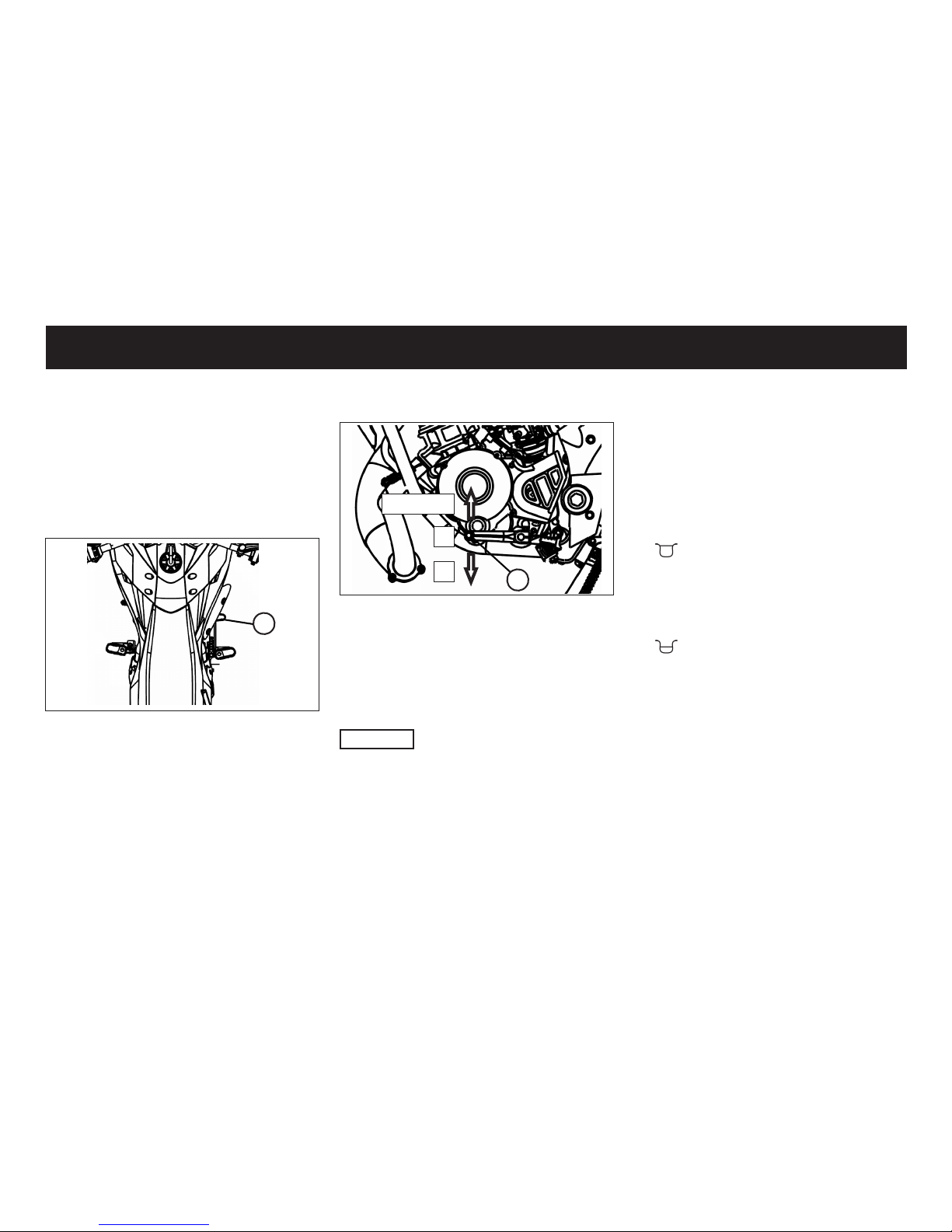
The brake lever is for the front brake is
located in the right side of the handlebar. Pull back the lever to operate the
brake.
BRAKE PEDAL
1
The brake pedal (1) is located on the
right-hand side of the vehicle and operates the rear brake. Familiarise yourself with how it works before you ride
the vehicle on public roads. Novices
and returning riders are recommended
to take a riding techniques course.
CLUTCH PEDAL
1
1
6,5,4,3,2
N
The clutch pedal (1) is located on the
left side of the vehicle. The possible
switching positions you see in the picture. The idle is between rst and second gear.
CAUTION
Never attempt to change gear without
releasing the clutch. Novices and returning riders are recommended to take a
riding techniques course.
FUEL COCK
1. ▪ OFF
No petrol can ow from the fuel tank
to the carburettor. Always turn the
petrol tap to the OFF position as
soon as you have parked the vehicle.
2. ON
Turn the petrol tap to this position
before you attempt to start the ve-
hicle. Petrol ows from the fuel tank
to the carburettor.
3. RESERVE
Irregular vehicle behaviour is often caused by a lack of fuel. In this
event, turn the petrol tap to the RES
position.
INSTRUMENT AND CONTROL FUNCTIONS
18
Page 20
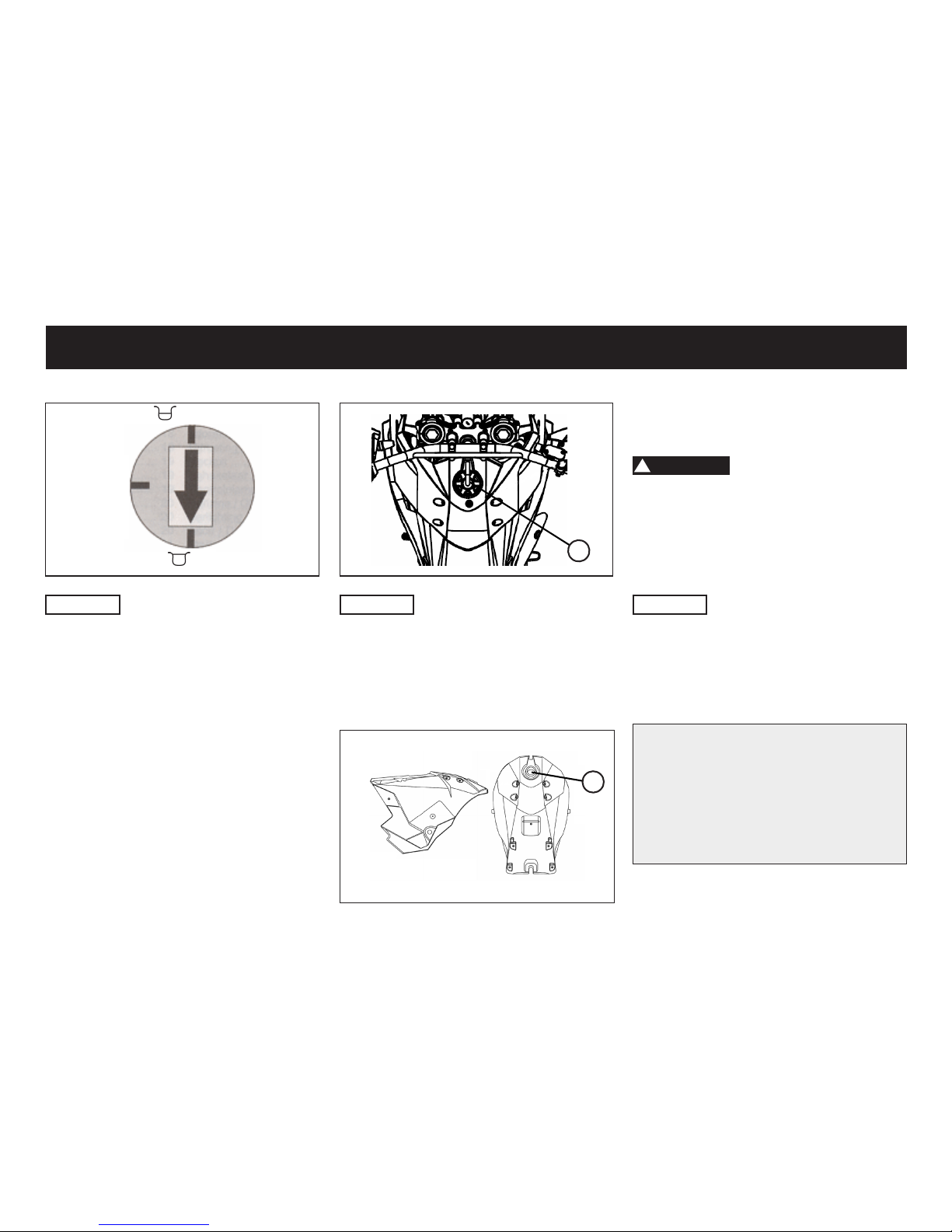
Make sure that there is sufcient fuel in
the tank. Fill the fuel tank to the bottom
of the ller tube as shown.
!
WARNING
• Do not overll the fuel tank, otherwise it may overow when the fuel
warms up and expands.
• Avoid spilling fuel on the hot engine.
CAUTION
Immediately wipe off spilled fuel with
a clean, dry, soft cloth, since fuel may
damage the painted surfaces or plastic
parts.
Regular unleaded gasoline only.
Recommended fuel: 95 oct
10 l +/- 0,2l
!!CAUTION!!
BIOETHANOL E10 IS NOT SUITABLE
1
CAUTION
Make sure that the fuel tank cap is properly closed and locked before riding.
FUEL
1
INSTRUMENT AND CONTROL FUNCTIONS
RESERVE
ON
▪ OFF
CAUTION
If you need switch to the RESERVE
position, visit a lling station at the earliest opportunity to refuel.
FUEL TANK CAP
To open the fuel tank cap (1) you have
to turn it counterclockwise. After refueling, you must turn it clockwise to close.
19
Page 21
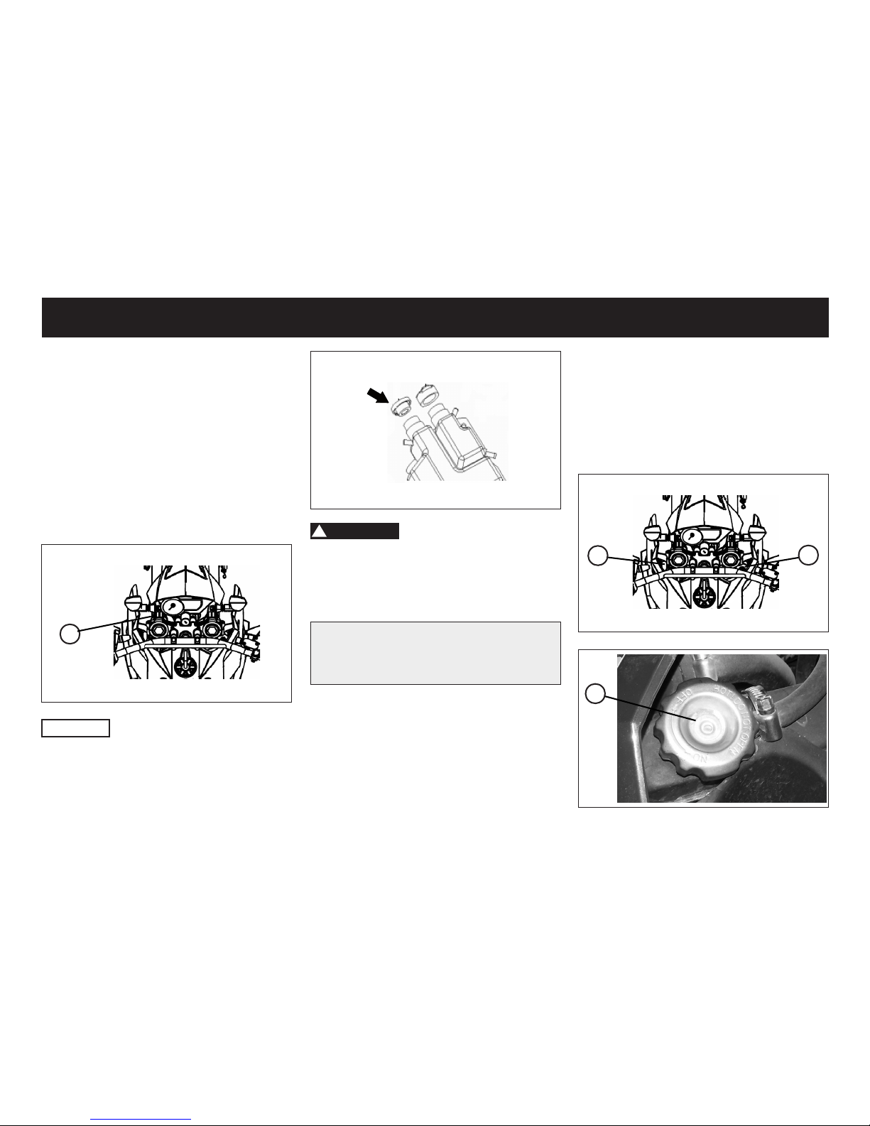
OIL TANK CAP
The oil tank (1) is located under the fuel
tank on front left side.
1. Remove the 2-stroke oil tank cap by
unscrew it.
2. Top up the oil.
3. Install the 2-stroke oil tank cap by
screw it into the oil tank opening.
1
CAUTION
Make sure that the 2-stroke oil tank
cap is properly installed before riding
the vehicle.
!
WARNING
At each refuelling you have to controll
the engine 2-stroke oil.
Capacity: 1 l
Recommendation:
Castrol Power 1 Racing 2T
RADIATOR AND COOLANT RESERVOIR
The radiator (2) is located under the
fuel tank on the right front side.
The coolant reservoir (1) is located under the fuel tank on the front left side.
1. Remove cap by unscrew it.
2. Top up the coolant
3. Install the cap by screw it into.
1
2
1
INSTRUMENT AND CONTROL FUNCTIONS
20
Page 22
2
Capacity: 1 -1,5 l
Recommended coolant:
CASTROL RADICOOL PREMIX
CAUTION
Make sure that the cap is properly installed before riding the vehicle.
CATALYTIC CONVERTER
This model is equipped with a catalytic
converter in the exhaust system.
!
WARNING
The exhaust system is hot after operation. Make sure that the exhaust system has cooled down before doing any
maintenance work.
CAUTION
The following precautions must be ob-
served to prevent a re hazard or other
damages.
• Use only unleaded gasoline. The
use of leaded gasoline will cause
unrepairable damage to the catalytic
converter.
• Never park the vehicle near possible
re hazards such as grass or other
materials that easily burn.
• Do not allow the engine to idle too
long.
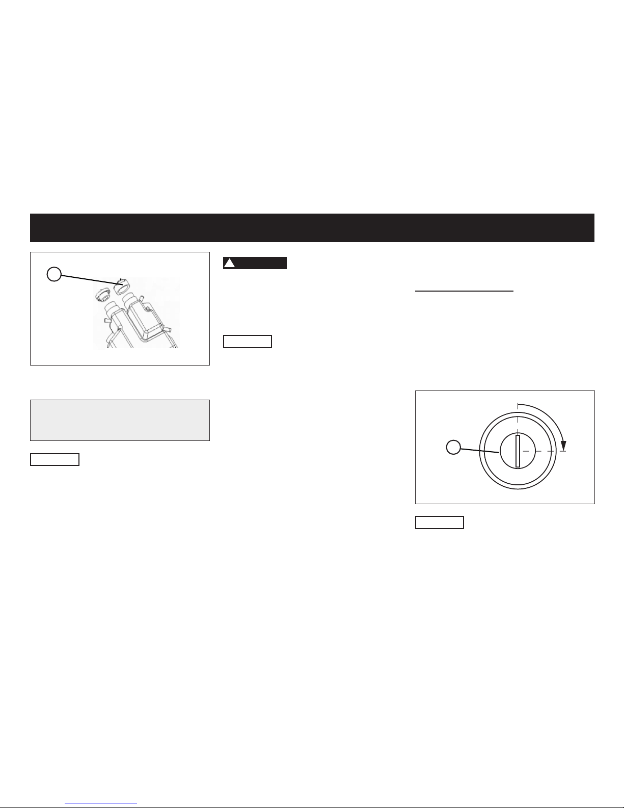
SEAT
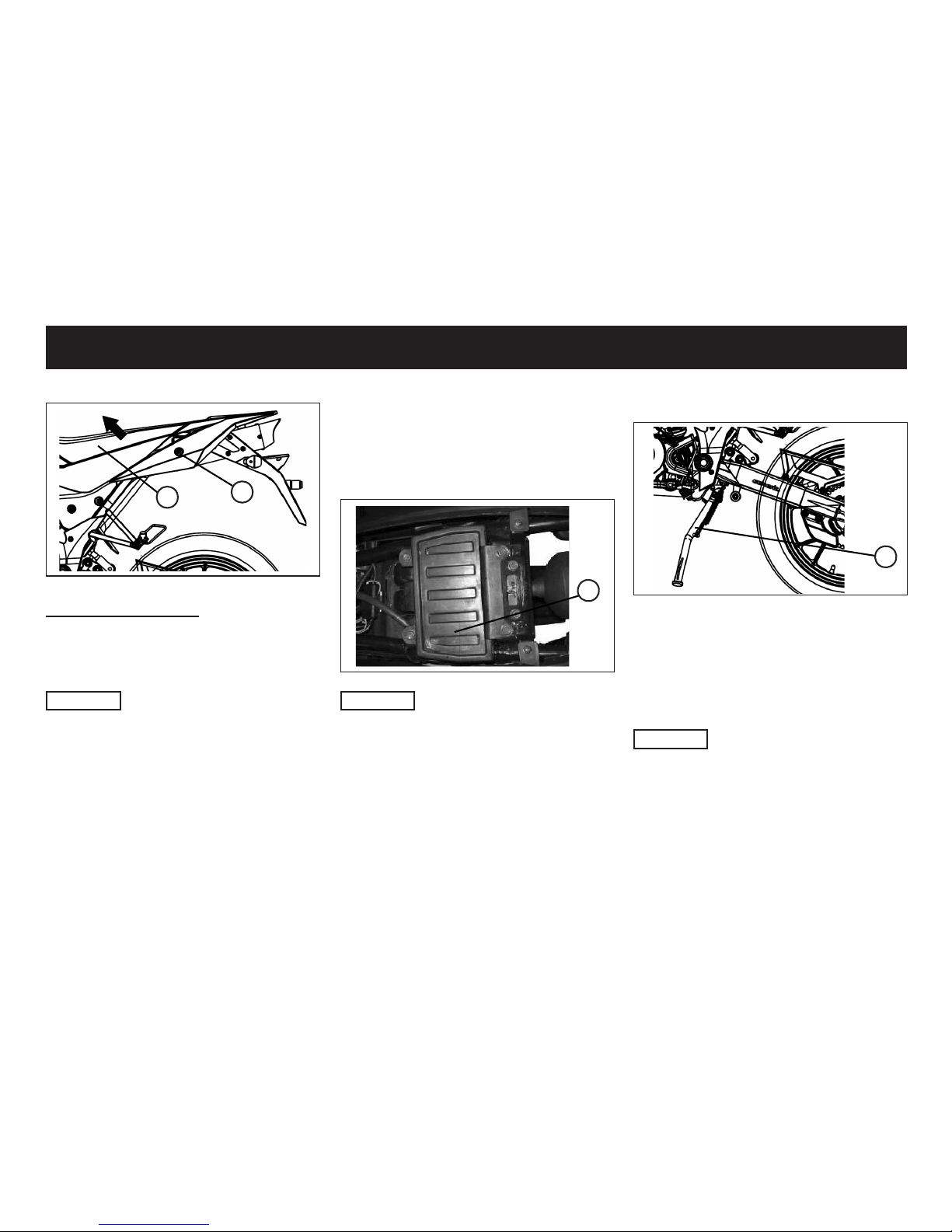
To open the seat (2)
1. Place the vehicle on the side stand.
2. Insert the key in the lock (1) which is
located under sead on the left side
3. Turn the key about 1/4 turn clockwise.
4. The lock is unlocked and the seat
opens and you can fold it up.
1
CAUTION
Do not push inward when turning the
key.
INSTRUMENT AND CONTROL FUNCTIONS
21
Page 23
1
2
To close the seat (2)
Fold down the seat and press it directly over the lock with the palm of your
hand into it.
CAUTION
• When you close the seat by force
or strike, parts can be damaged.
• Make sure that the seat is locked
before driving or when you park
the vehicle.
OWNER’S TOOL KIT
The owner‘s tool kit is located in the
tool box (1) under the seat and can be
used for repairs.
1
CAUTION
• Since the tool box will accumulates
heat by the heat of sun and engine,
please do not put any thing that sentitive to the heat.
• Do not put anything valuable or
breakable objects in the storage luggage box.
SIDE STAND
1
The side stand (1) is located on the left
side of the Vehicle. Release the sidestand by using your feet to step on the
bracket of side stand to up-right position to stand the vehicle.
CAUTION
• The side stand with auto-rebound
system. Make sure your vehicle have been park well are stable
enough to stand the vehicle.
• Please avoid to use side stand to
park the vehicle on the slope, soft
land or un-at ground.
INSTRUMENT AND CONTROL FUNCTIONS
22
Page 24

PRE-OPERATION CHECKS
The condition of a vehicle is the owner’s responsibility. The operator should check the vehicle by simple but thorough
inspection,to make sure of vehicle condition, quick inspect some key and important parts, to prevent the vehicle from serious consquence/accident. Please carefully check the following points before each ride.
CAUTION
Pre-operation checks should be made each time the vehicle is used. Such an inspection can be accomplished in a very
short time; and the added safety it assures is more than worth the time involved.
!
WARNING
If any item in the Pre-operation check list is not working properly , have it inspected and repaired before operating
the vehicle. If failed to be corrected by yourself, please turn to repair shop immediately.
If failed to be corrected by yourself, please turn to repair shop immediately.
23
Page 25
PRE-OPERATION CHECKS
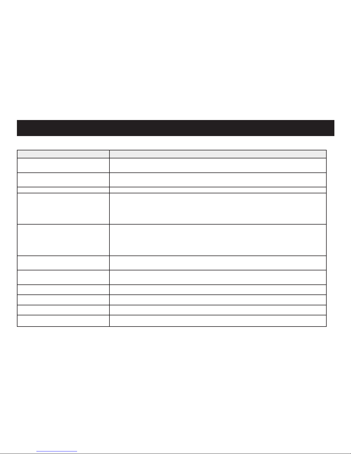
PRE-OPERATION CHECK LIST
CHECKPOINT TO VERIFY
Fuel • Check fuel level in fuel tank.
• Refuel if necessary.
• Check fuel line for leakage.
Engine oil • Check oil level in oil tank.
• If necessary, add recommended oil to specied level.
• Check vehicle for oil leakage.
Final transmission oil • Check vehicle for oil leakage.
Front brake • Check operation.
• If soft or spongy, have dealer bleed hydraulic system.
• Check brake pads for wear.
• Replace if necessary.
• Check uid level in reservoir.
• If necessary, add recommended brake uid to specied level.
• Check hydraulic system for leakage.
Rear brake • Check operation.
• If soft or spongy, have dealer bleed hydraulic system.
• Check brake pads for wear.
• Replace if necessary.
• Check uid level in reservoir.
• If necessary, add recommended brake uid to specied level.
• Check hydraulic system for leakage.
Throttle grip • Make sure that operation is smooth.
• Check cable free play.
• If necessary, have dealer adjust cable free play and lubricate cable and grip housing.
Wheels and tires • Check for damage.
• Check tire condition and tread depth.
• Check air pressure.
Brake levers • Make sure that operation is smooth.
• Lubricate lever pivoting points if necessary.
Side stand • Make sure that operation is smooth.
• Lubricate pivot if necessary.
Chassis fasteners • Make sure that all nuts, bolts and screws are properly tightened.
• Tighten if necessary.
Instruments, lights, signals and switches • Check operation
• Correct if necessary
24
Page 26
OPERATION AND IMPORTANT RIDING POINTS
!
WARNING
• Before riding the vehicle, please
make sure that you are fully miliar with all operating controls &
their functions before riding. To
consult a dealer shop if you not
thoroughly understand.
• Please do not start the engine in
a closed area, the exhaust air are
poisonous, and inhaling them can
cause loss of consciousness and
even death in short time.
CAUTION
• When engine is cold set the choke
on the close position, use the kickstarter or the electric starter to start
the engine. Then set the choke on
the midway position in order to warm
the engine. At last set the choke on
the open position, if the engine operates smoothly, it implies the warmed engine.
• When engine is warm do not use the
choke system.
• Do not crank the engine more than 5
seconds on any one attempt.
Starting with the kickstarter
1. Turn the fuel cock to the position
ON
2. Turn the key to ON .
3. Insert the neutral gear.
4. Unfold the kickstart lever (1) and
push with your foot down until you
see a noticeable resistance.
5. Then kick the kickstarter evenly and
powerfully downwards.
STARTING THE ENGINE
CAUTION
Note the point „Engine break in“ before
you start to riding the vehicle.
1
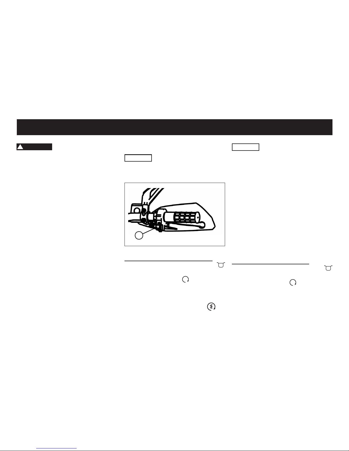
Starting with the electric starter
1. Turn the fuel cock to the position
ON
2. Turn the key to ON .
3. Insert the neutral gear.
4. Pull the right brake lever otherwise
the vehicle will not start.
5. Push the start swich button (1)
for a few seconds.
25
Page 27
CAUTION
Before driving allow the engine to
warm up otherwise the spark plug and
engine can be damaged early.
STARTING OFF
1. Pull the clutch lever
2. Shift the engine to the rst gear
3. Slowly release the clutch lever and
open the throttle at the same time.
SHIFTING AND RIDING
a) Shifting gears upwards
1. Release the throttle
2. Pull the clutch lever
3. Lift the gear lever upwards to change
to the higher gears.
4. Slowly release the clutch lever and
open the throttle at the same time.
b) Shifting gears downwards
1. Release the throttle
2. Operate the brakes and reduce the
speed to a appropriate speed.
3. Pull the clutch lever
4. Lift the gear lever down wards to
change to the lower gears.
5. Slowly release the clutch lever and
open the throttle at the same time.
!
WARNING
Always switch one gear only, otherwise
the transmission can be damaged.
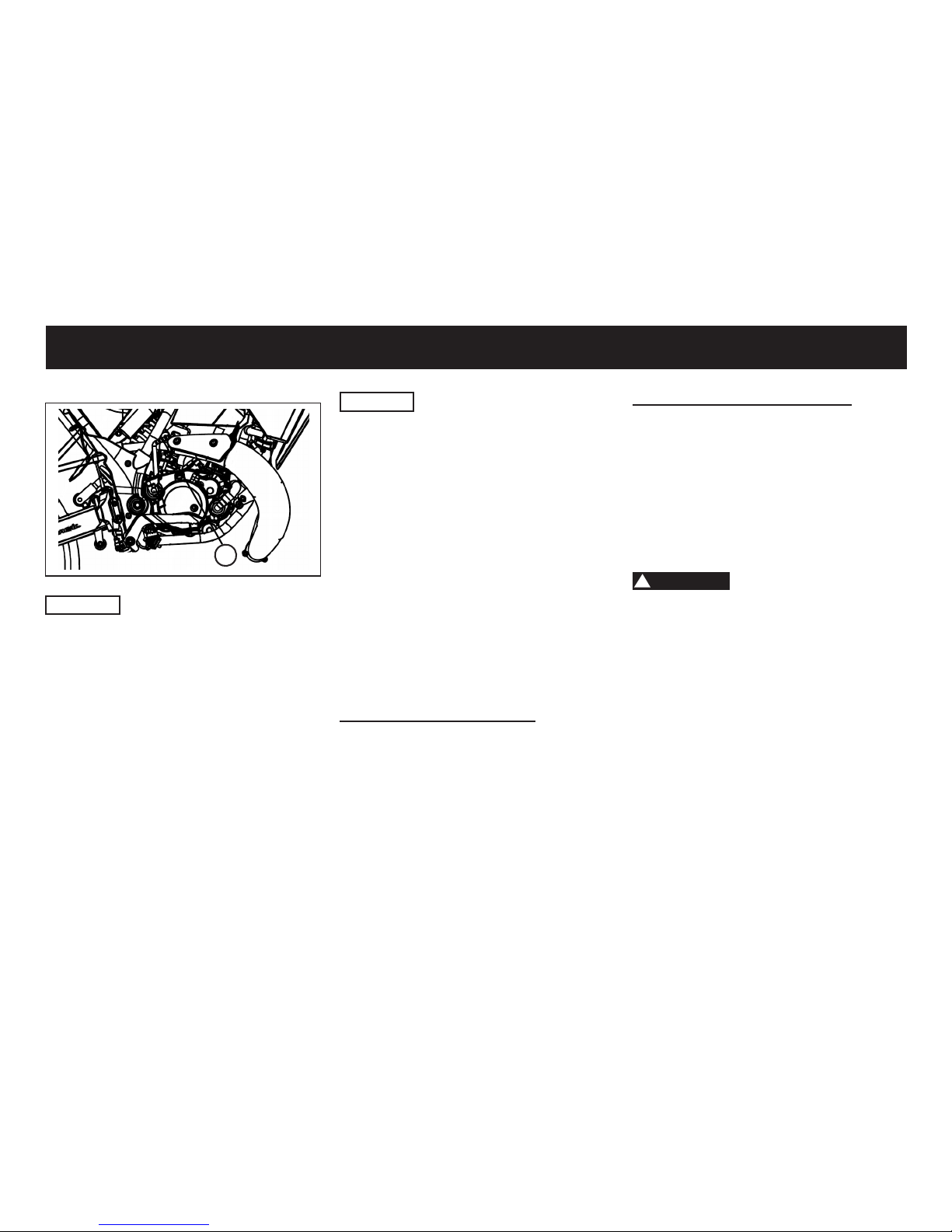
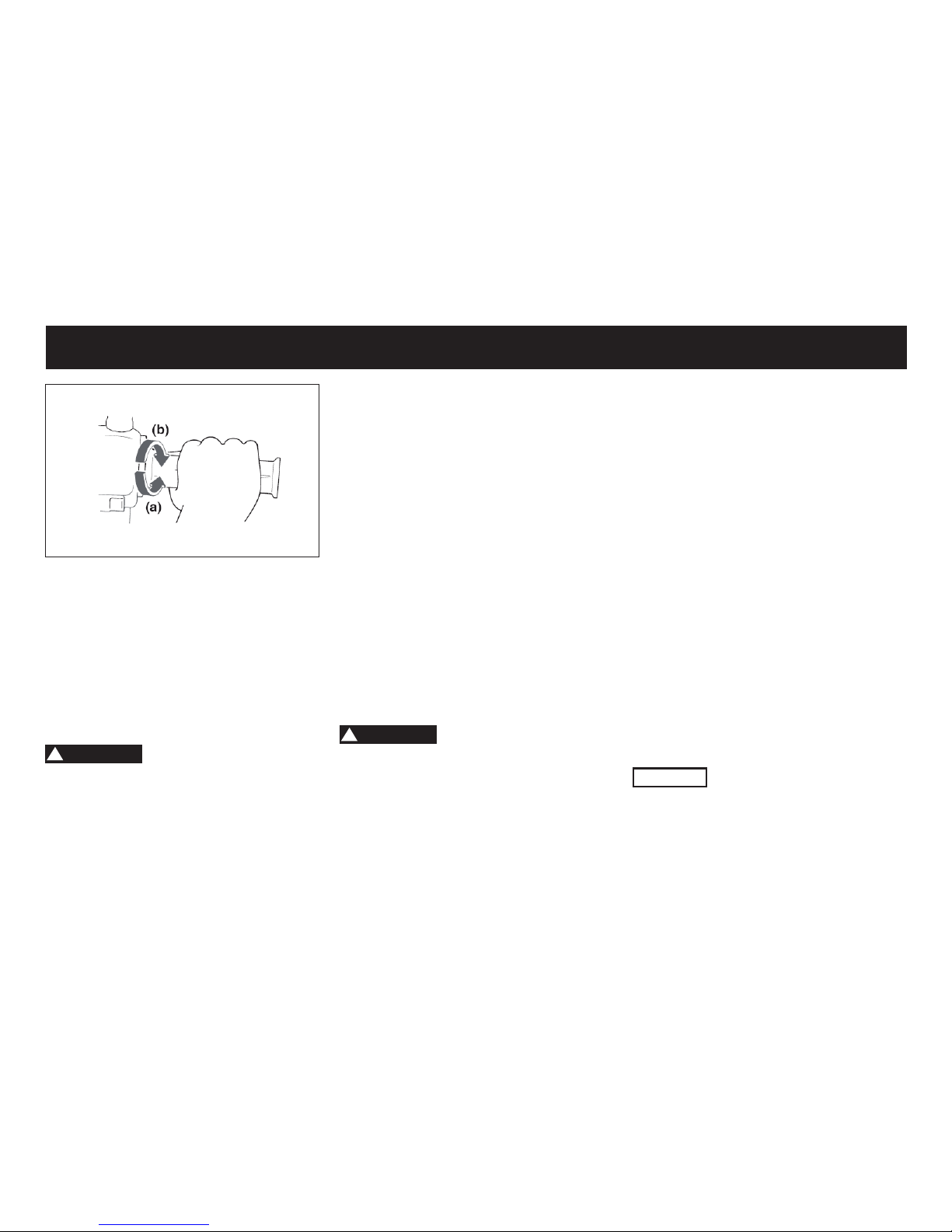
ACCELERATION AND DECELERATION
The speed can be adjusted by opening
and closing the throttle. To increase the
speed, turn the throttle grip in direction
(a). To reduce the speed, turn the throttle grip in direction (b).
1
CAUTION
• The engine starts immediately upon
actuation of the starter, then wait a
few seconds before you try to start it
again. Each starting process should
be as short as possible in order to
save battery and the starter.
• The vehicle must periodically (re-
commended weekly) start with the
kick starter, otherwise the grease
can gum up the kick starter gear and
the kick starter not to operate. den
Anlasser zu schonen.
OPERATION AND IMPORTANT RIDING POINTS
26
Page 28
STOP THE ENGINE
1. Reduce the throttle to 0 position.
2. Pull the clutch lever
3. Switch the gear to N - neutral
4. Operate the brakes
5. After the vehicle is stopped turn off
the ignition.
ENGINE BREAK IN
During the rst 1000 km do not ride
the vehicle over 75% of its maximum
speed. Avoid opening the accelerator
completely and varies speed repea-
tedly over long distances. After the rst
1000 km increase speed gradually until
reaching maximum performance.
CAUTION
• The durability and the efciency of
your scooter depend strongly on the
care received during the run-in period. The mechanisms of the mobile parts are mutually hardened and
adapted.
BRAKING
1. Release the throttle.
2. Apply the clutch lever gradually increasing the pressure.
3. Apply the front and rear brake at the
same time.
!
WARNING
• Avoid hard or sudden braking (especially when cornering) otherwise the
motorcycle may skid.
• Railroad crossings, street-car rails,
iron plates on road construction sites, and manhole covers become
extremely slippery when wet.
• Therefore slow down when approaching such areas and cross them
with caution.
PARKING
1. Reduce the throttle to 0 position.
2. Pull the clutch lever
3. Switch the gear to N - neutral
4. Operate the brakes
5. After the vehicle is stopped turn
off the ignition.
6. Lower the side stand with your foot
while holding the motorcycle upright. Remove the key from the main
switch.
!
WARNING
Since the engine and exhaust system
can become very hot, park in a place
where pedestrians or children are not
likely to touch them.
Do not park on a slope or on soft
ground, otherwise the vehicle may
overturn.
OPERATION AND IMPORTANT RIDING POINTS
27
Page 29

• After better run-in is obtained not by
riding slowly but softly and carefully. During this period, it is advisable
to ride the vehicle at ¾ of maximum
performance. In the event that full
acceleration is necessary (overtaking maneuvers, steep slopes, etc.)
try to limit the time to a minimum.
• Gearbox oil must be changed once
the rst 1000 km are covered. Use
the recommended oil type and spe-
cied quantity only.
The durability and the efciency of your
scooter depend strongly on the care
received during the run-in period. The
mechanisms of the mobile parts are
mutually hardened and adapted.
After better run-in is obtained not by riding slowly but softly and carefully. During this period, it is advisable to ride
the vehicle at 3/4 of maximum performance. In the event that full accelera-
tion is necessary (overtaking maneuvers, steep slopes, etc.) try to limit the
time to a minimum.
OPERATION AND IMPORTANT RIDING POINTS
Gearbox oil must be changed once
the rst 1000 km are covered. Use the
recommended oil type and specied
quantity only.
To obtain optimum adjustment of mobile parts, a long life and better performance, it is necessary not to force the
vehicle during the 1000 km. The vehicle must have a suitable run-in period,
during which the following precautions
must be considered:
• After starting the engine, warm it up
progressively, without maximum acceleration (we recommend not to exceed 3/4 of the throttle grip opening
for 1st gear) or overcharge.
• In long stretches, do not use full
speed consistently and varies the
speed repeatedly.
• When facing steep slopes, downshift to have better power.
• After a long run do not stop the engine suddenly, leave it running at
minimum acceleration for some seconds.
• Check the non-existence of oil, fuel
or brake liquid leaks.
• In case of anomalous noise, try to
identify its cause immediately.
28
Page 30

CAUTION
Most of the Safety and condition of vehicle depend on how you do the correct maintenance , periodic inspection,
adjustment and lubrication. The following are contents that help the operator to do such skills on the following pages.
!
WARNING
Maintenance, replacement, or repair of the emission control devices and systems may be performed by any repair shop or
individual that is certied and must follow the local law regulations.
If you are not familiar with maintenance work, have a dealer do it for you.
PERIODIC MAINTENANCE AND MINOR REPAIR
29
Page 31
SPARK PLUG
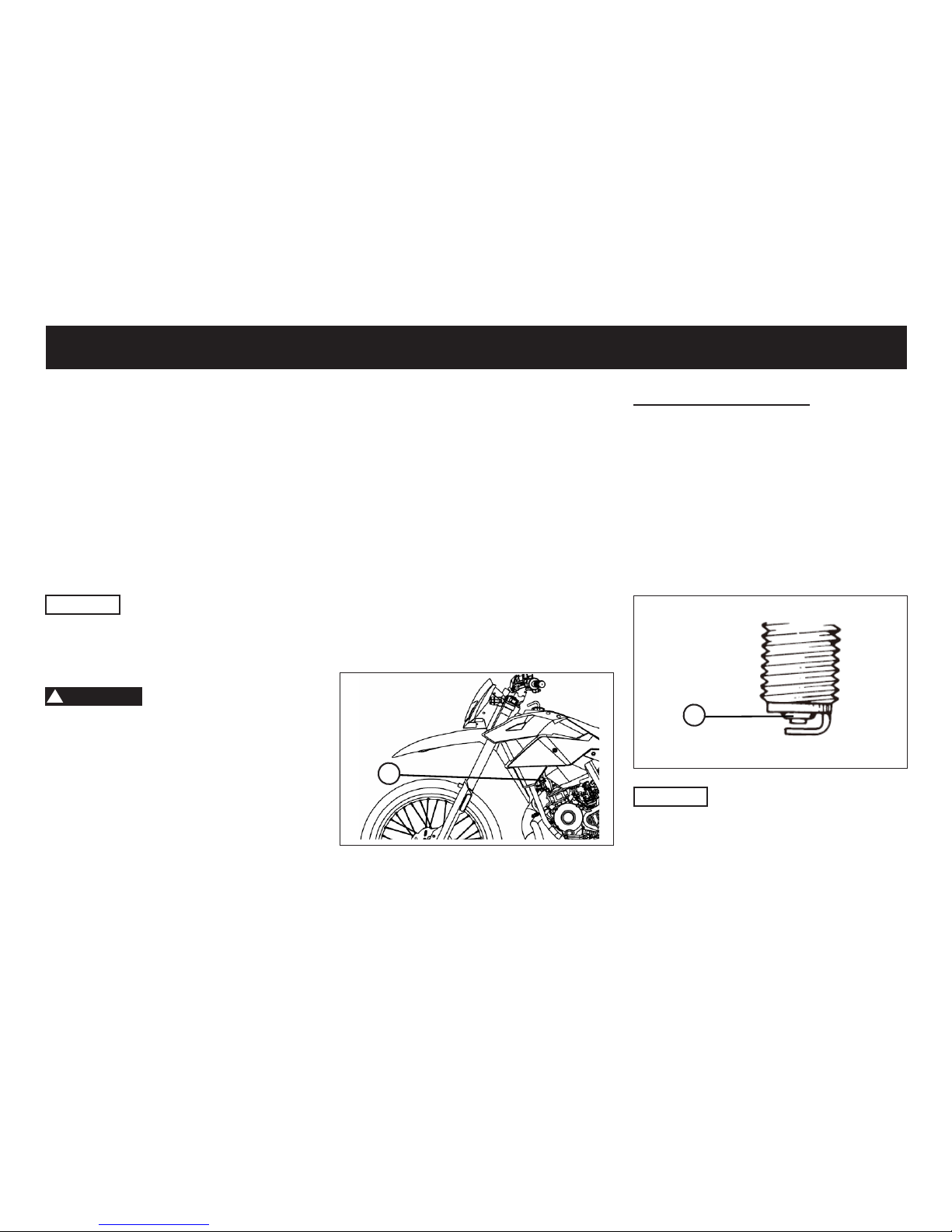
The spark plug is an important engine
component, which is easy to check.
Since heat and deposits will cause any
spark plug to slowly erode, the spark
plug should be removed and checked
in accordance with the periodic maintenance and lubrication chart. In addition, the condition of the spark plug can
reveal the condition of the engine.
The spark plug (1) is on the left front of
the vehicle.
1
Remove the spark plug
1. Remove the spark plug cap
2. Remove the spark plug, with the
spark plug wrench included in the
owner’s tool kit.
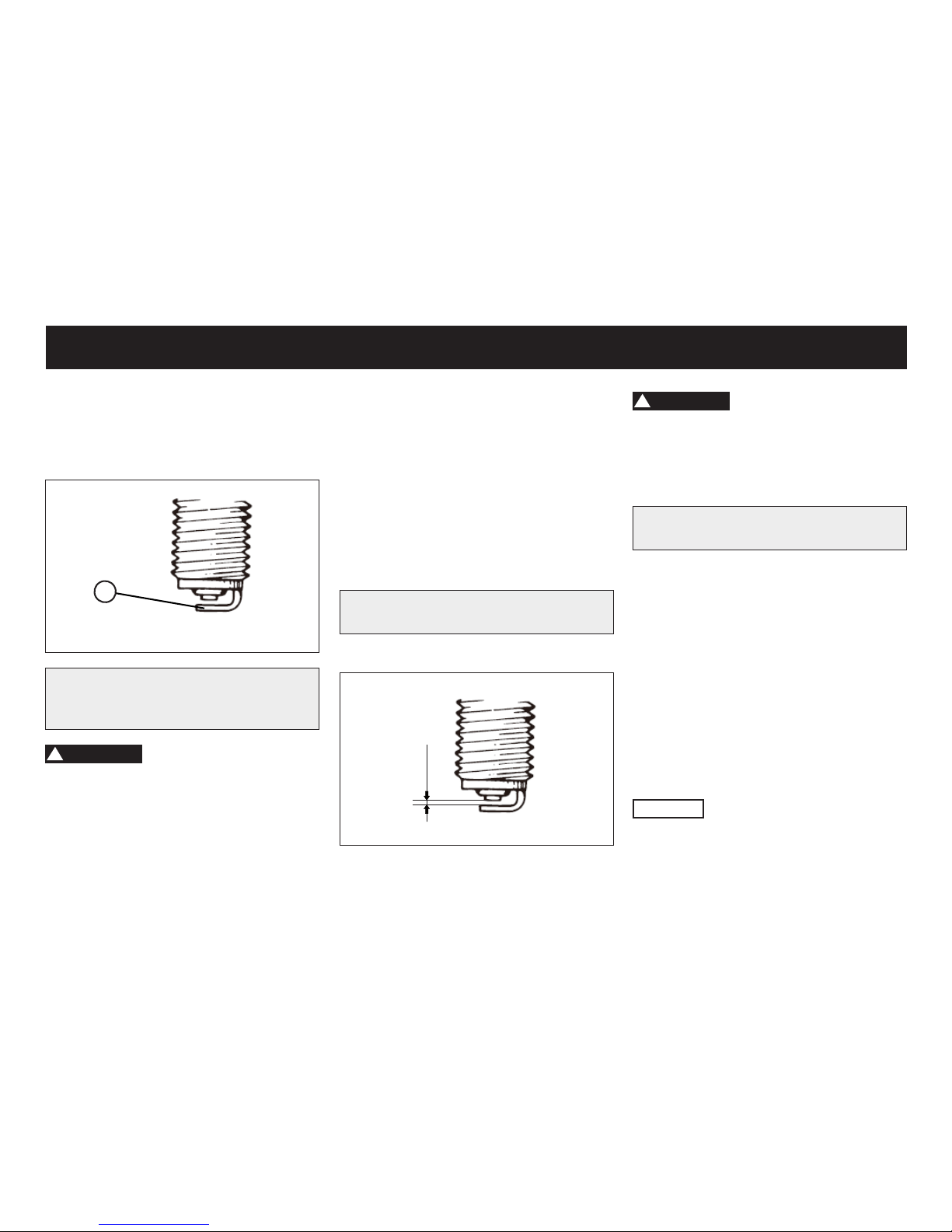
3. Check that the porcelain insulator
(2) around the center electrode of
the spark plug is a medium-to-light
tan (the ideal color when the vehicle
is ridden normally).
2
CAUTION
If the spark plug shows a distinctly different color, the engine could be operating improperly. Do not attempt to diagnose such problems yourself. Instead,
have a dealer check the vehicle.
OWNER’S TOOL KIT
The service information included in this
manual and the tools provided in the
owner’s tool kit are intended to assist
you in the performance of preventive
maintenance and minor repairs. However, additional tools such as a torque
wrench may be necessary to perform
certain maintenance work correctly.
CAUTION
If you do not have the tools or experi-
ence required for a particular job, have
a dealer perform it for you.
!
WARNING
Modications not approved by maker
may cause loss of performance, excessive emissions, and render the vehicle
unsafe for use. Consult a dealer before
attempting any changes.
Modications without authorization of
the manufacturer cause void the warranty.
PERIODIC MAINTENANCE AND MINOR REPAIR
30
Page 32
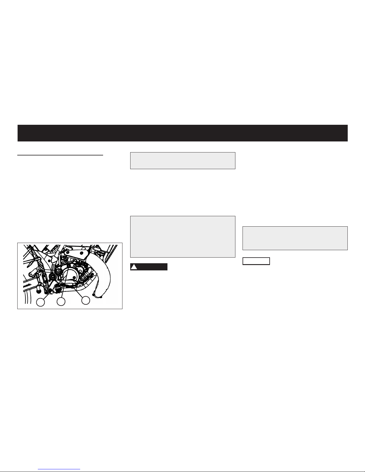
5. Measure the spark plug gap with a
wire thickness gauge and, if neces-
sary, adjust the gap to specication.
Clean the surface of the spark plug
gasket and its mating surface, and
then wipe off any grime from the
spark plug threads.
6. Install the spark plug with the spark
plug wrench, and then tighten it to
the specied torque.
Spark plug gap: 0,6 - 0,7 mm
0,6-0,7 mm
31
4. Check the spark plug for electrode
(3) erosion and excessive carbon or
other deposits, and replace it if necessary.
3
Specied spark plug:
NGK BR8ES
!
WARNING
Please note that no other spark plug
model is allowed. Using a different
spark plug model can immediately lead
to engine damage.
!
WARNING
Please note the max. torque when inserting the plug. If you do not have the
ability to control you leave control of
the spark plug to the dealer.
Tightening torque: 12 Nm
FINAL TRANSMISSION OIL
The nal transmission case (1) must
be checked for oil leakage before each
ride. If any leakage is found, have a
dealer check and repair the vehicle. In
addition, the nal transmission oil must
be changed as follows at the intervals
specied in the periodic maintenance
and lubrication chart.
CAUTION
As long as the vehicle is within the warranty period the dealer is responsible
to change the gear oil.
PERIODIC MAINTENANCE AND MINOR REPAIR
Page 33
Tightening torque: 18 Nm
6. Add the requested amount of the
recommended nal transmission oil,
and then install and tighten the oil
ller cap.
Recommended nal transmission
oil:
Castrol Power 4T 10W40 or ATF Öl
Oil quantity: Full: 0,5 l / Change: 0,4 l
!
WARNING
• Make sure that no foreign material
enters the nal transmission case.
• Make sure that no oil gets on the tire
or wheel.
7. Check the nal transmission case
for oil leakage. If oil is leaking, check
for the cause.
Change nal transmission oil
1. Start the engine, warm up the nal
transmission oil by riding the vehicle
for several minutes, and then stop
the engine.
2. Place the vehicle on the main stand.
3. Place an oil pan under the nal trans-
mission case to collect the used oil.
4. Remove the oil ller cap (2) and
drain bolt (3) to drain the oil from the
nal transmission case.
1
2
3
5. Install the nal transmission oil drain
bolt, and then tighten it to the speci-
ed torque.
COOLANT
Before you start operating the vehicle, check the coolant level. The radi-
ator should be completely lled with
coolant. The reservoir is located right
in front of the tank xed to the frame.
In the expansion tank, the coolant
should be between the MIN and MAX
mark stand.
Recommended coolant:
CASTROL RADICOOL PREMIX
CAUTION
The new lling and bleeding of the cooling system should be carried out by a
dealer.
AIR FILTER
The air lter should be replaced according to the maintenance schedule.
Replace the air lter more often if you
drive in unusually wet or dusty areas.
32
PERIODIC MAINTENANCE AND MINOR REPAIR
Page 34
CAUTION
• Make sure that the air lter element is
properly seated in the air lter case.
• The engine should never be operated without the air lter element installed, otherwise the piston and/or
cylinder may become excessively
worn.
CARBURETOR
The carburetor is an important part of
the engine and its emission control system, which requires very sophisticated
adjustment. Therefore, carburetor adjustments should be left to dealer, who
has the necessary professional knowledge and experience.
IDLING SPEED
If the idle is not correct consult a dealer
to check it.
33
PERIODIC MAINTENANCE AND MINOR REPAIR
The minimum speed of the engine
(idling) must be approxemately 1800
±100 rev/min.
THROTTLE CABLE FREE PLAY
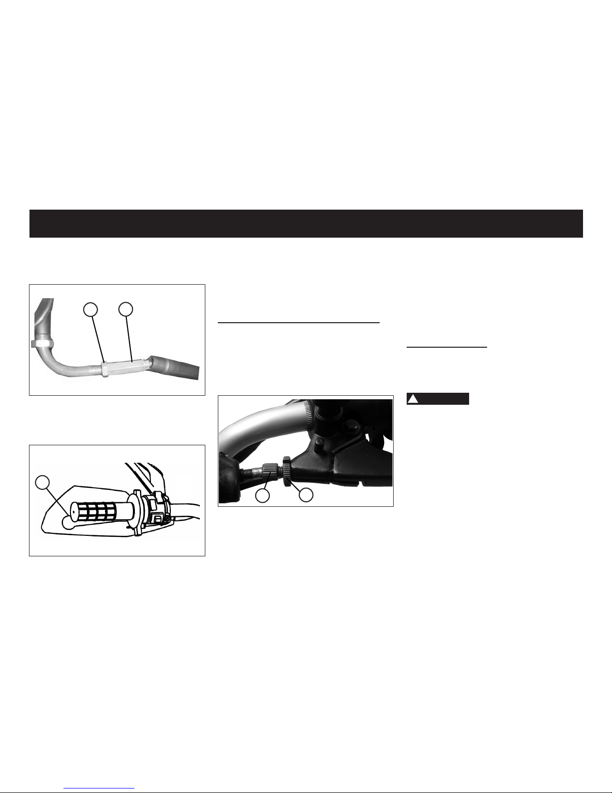
1
The throttle cable free play (1) should
measure 1.5 ~ 3.5 mm at the throttle grip. Periodically check the throttle
cable free play and, if necessary, have
a dealer adjust it.
Throttle cable free play adjustment
1. Release the locknut (1)
2. Rotate the adjusting nut (2) to ad-
just the clearance.
1
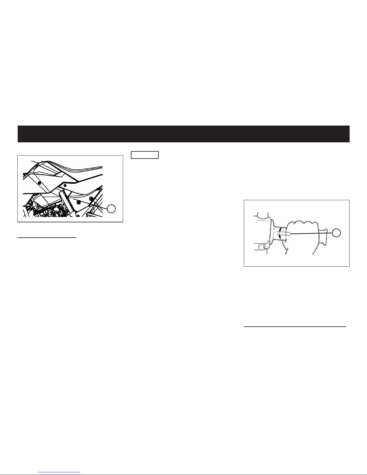
Replace the air lter
1. Remove the seat
2. Remove the side cover
3. Unscrew the screws of the air lter
housing (1).
4. Pull the air lter out.
5. Replace the lter with a new one.
6. Coat the mating surfaces of the air
lter case and air lter case cover
lightly with grease for an airtight
seal.
7. Install the air lter.
8. Mount the air lter housing.
9. Mount the side cover
10. Install the seat.
Page 35
34
The clutch lever free play (1) should
measure 1.0 ~ 2.0 mm. Periodically
check the clutch lever free play and if
necessary, have a dealer adjust it.
Clutch lever free play adjustment
1. Release the locknut (1)
2. Rotate the adjusting nut (2) to ad-
just the clearance.
3. Tighten the lock nut (1) after adjustingthe nut (2).
1
2
3. Tighten the lock nut (1) after adjustingthe nut (2).
1
2
CLUTCH LEVER FREE PLAY
1
TIRES
To maximize the performance, durability, and safe operation of your vehicle,
note the following points regarding the
specifed tires.
Tire air pressure
The tire air pressure should be che-
cked and, if necessary, adjusted before
each ride.
!
WARNING
The tire air pressure must be checked
and adjusted on cold tires (i.e., when
the temperature of the tires equals the
ambient temperature).
The tire air pressure must be adjusted
in accordance with the riding condition.
If you are not familiar to this, please
have dealer for help.
PERIODIC MAINTENANCE AND MINOR REPAIR
Page 36
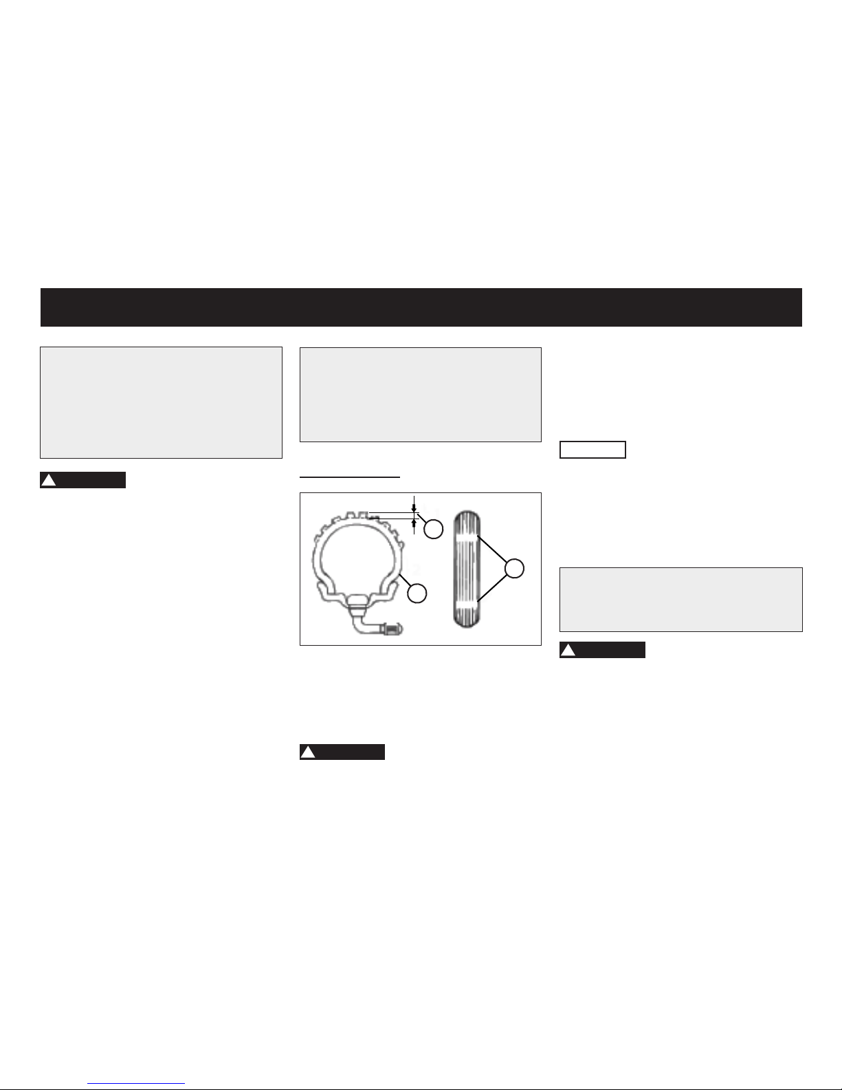
If a tire tread shows crosswise lines
(minimum tread depth), if the tire has
a nail or glass fragments in it, or if the
sidewall is cracked, have a dealer replace the tire immediately.
CAUTION
The tread depth may vary depending
on country. Observe local regulations.
The values listed here are technical values and may differ from the legal values of your region.
Minimum tire tread depth:
Front and rear: > 1,6 mm
!
WARNING
• Drive with worn tire is illegal, reduces stability and can lead to loss of
control over the vehicle.
• Let worn or damaged tires replaced
immediately by your dealer.
• Working tires and the dealer is responsible.
•
Maximum load*: 150 kg
* Total weight of rider, passenger,
cargo and accessories
Tire inspection
1
2
3
1. Tire tread depth
2. Tire sidewall
3. Tire wear indicator
!
WARNING
The tires must be checked before each
ride.
35
Tire air pressure:
Front: 2,1 bar - 2,5 bar
Rear: 2,1 bar - 2,5 bar
Total weight of rider, passenger,
cargo and accessories!
!
WARNING
Do not over load your vehicle, since
it will increase pressure on the tire,
braking, steering than original design,
and may could cause damge or even
lead to accident.
Allocation of your cargo and weight of
your vehicle is very important for your
own safety and vehicle performance.
Load your cargo rmly on vehicle and
put the heaviest cargo to the center
of vehicle, then distribute the weight
evenly from side to side. It will keep
you to have good steering after load.
PERIODIC MAINTENANCE AND MINOR REPAIR
Page 37
BRAKE LEVER FREE PLAY / BRAKE PEDAL FREE PLAY
CAUTION
There should be no free play at the brake lever end. If there is free play, have
a dealer inspect the brake system.
!
WARNING
A soft or spongy feeling in the brake
lever can indicate the presence of air
in the hydraulic system. If there is air
in the hydraulic system, have a dealer
bleed the system before operating the
motorcycle. Air in the hydraulic system
will diminish the braking performance,
which may result in loss of control and
an accident.
Rear brake
CAUTION
There should be no free play at the
brake padal‘s end. If there is free play,
have a dealer inspect the brake system.
RIMS
To maximize the performance, durability, and safe operation of your motorcycle, note the following points regarding
the specied wheels.
• The wheel rims should be checked
for cracks, bends or warpage before each ride. If any damage is found,
have a dealer replace the wheel. Do
not attempt even the smallest repair
to the wheel. A deformed or cracked
wheel must be replaced.
• The wheel should be balanced whenever either the tire or wheel has
been changed or replaced. An unbalanced wheel can result in poor performance, adverse handling characteristics, and a shortened tire life.
• Ride at moderate speeds after changing a tire since the tire surface must
rst be “broken in” for it to develop its
optimal characteristics.
DIMENSIONS TIRE / RIMS
SM model
Front: Rim: 17x2.5
Tire: 100/80-17
Rear: Rim: 17x3.0
Tire: 130/80-17
TYRE TYPE: tubeless
DIMENSIONS TIRES / RIMS
X model
Front: Rim: 21x1.6
Tire: 100/80-17
Rear: Rim: 18x1.85
Tire: 130/80-17
TYRE TYPE: tubeless
36
PERIODIC MAINTENANCE AND MINOR REPAIR
Page 38
37
!
WARNING
If proper adjustment cannot be obtained as described contact a dealer to
make this adjustment.
BRAKE PADS
The brake pads must be checked for
wear at the intervals specied in the
periodic maintenance and lubrication
chart.
Each brake pad is provided with wear
indicators, which allows you to check
the brake pad wear without having to
!
WARNING
A soft or spongy feeling in the brake
padel can indicate the presence of air
in the hydraulic system. If there is air
in the hydraulic system, have a dealer
bleed the system before operating the
motorcycle. Air in the hydraulic system
will diminish the braking performance,
which may result in loss of control and
an accident.
Brake padel free play
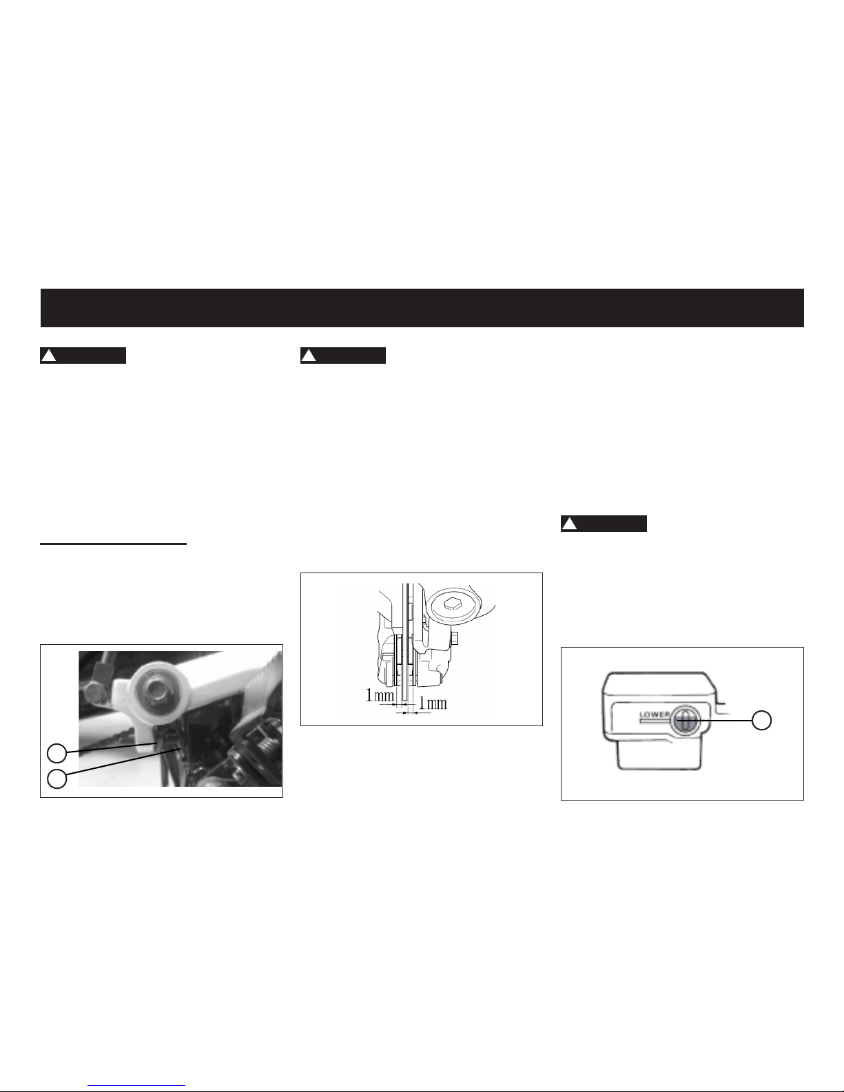
1. Loosen the locknut (1)
2. Turn the adjusting bolt (2) until the
lever position is within specied position (10 mm free play on the lever)
3. Tighten the locknut again.
1
2
disassemble the brake. To check the
brake pad wear, check the position of
the wear indicators while applying the
brake. If a brake pad has worn to the
point that a wear indicator almost touches the brake disc, have a dealer replace the brake pads as a set.
BRAKE FLUID
!
WARNING
Insufcient brake uid may allow air to
enter the brake system, possibly
causing it to become ineffective. Befo-
re riding, check that the break uid is
above the minimum level mark (1) and
rell it if necessary.
1
PERIODIC MAINTENANCE AND MINOR REPAIR
Page 39
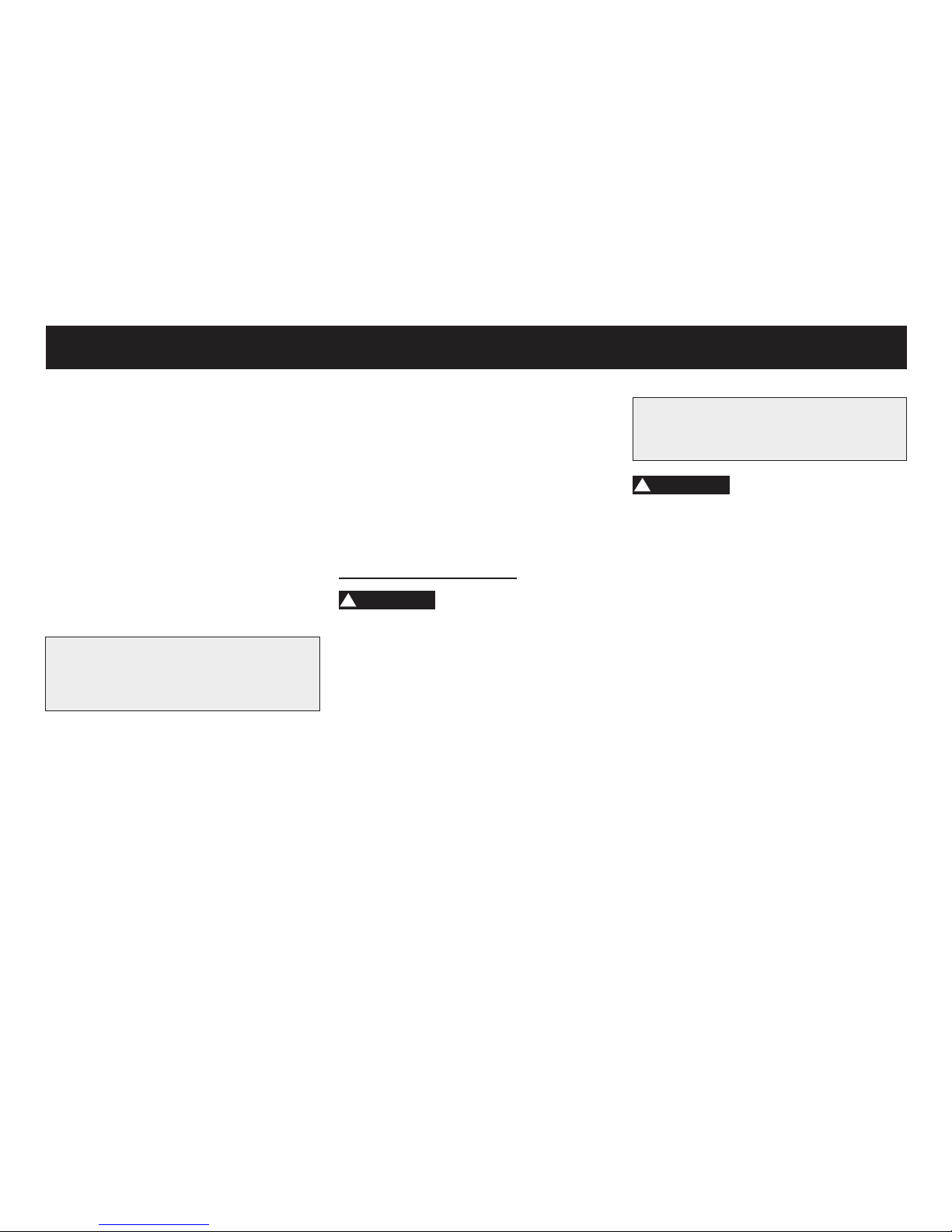
Recommended lubricant:
Castrol Motorrad DWF oilspray
!
WARNING
Damage to the outer housing of cables
may result in internal rusting and cause
interference with cable movement. Replace damaged cables as soon as possible to prevent unsafe conditions.
THROTTLE GRIP AND CABLE
The operation of the throttle grip should
be checked before each ride. In addition, the cable should be lubricated at
the intervals specied in the periodic
maintenance chart.
LUBRICATING THE FRONT AND
REAR BRAKE
The pivoting points of the front and rear
brake must be lubricated at the inter-
Low position brake uid level may indicate worn brake pads and/or brake
system leakage. If the brake uid level is low, be sure to check the brake
pads for wear and the brake system for
leakage. When checking the uid level,
make sure that the top of the master
cylinder is level by turning the handlebars. Use only the recommended qua-
lity brake uid, otherwise the rubber
seals may deteriorate, causing leakage
and poor braking performance.
Recommended brake uid:
Castrol Super Disc Brake Fluid DOT 4
• Rell with the same type of brake uid. Mixing uids may result in a harm-
ful chemical reaction and lead to poor
braking performance.
• Be careful that water does not enter
the master cylinder when relling.
Water will signicantly lower the boiling point of the uid and may result
in vapor lock.
38
• Brake uid may deteriorate painted
surfaces or plastic parts. Always clean
up spilled uid immediately.
A
• s the brake pads wear, it is normal
for the brake uid level to gradually
go down. However, if the brake uid
level goes down suddenly, have a
dealer check.
Chaning the brake uid
!
WARNING
Have a dealer change the brake uid
at the intervals specied in the NOTE
after the periodic maintenance and lubrication chart.
CABLES
The operation of all control cables
and the condition of the cables should
be checked before each ride, and the
cables and cable ends should be lubricated if necessary. If a cable is damaged or does not move smoothly, have
a dealer check or replace it.
PERIODIC MAINTENANCE AND MINOR REPAIR
Page 40
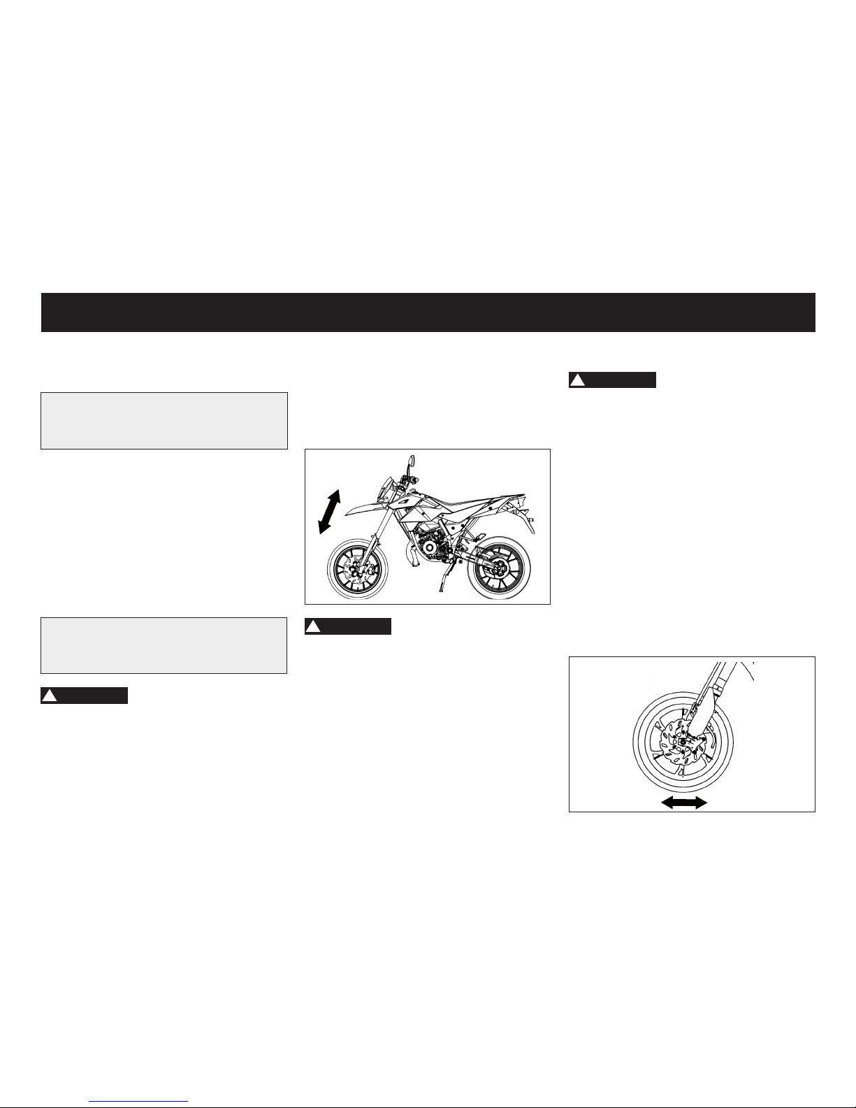
2. Check the inner tubes for scratches,
damage and oil leakage.
3. Apply the front brake and push the
handlebars several times down hard
to verify the suspension of the fork.
!
WARNING
• When damage to the fork, please
contact your dealer.
• If you treat the telescopic fork with
cleaning agents, make sure that they
get no contact with the tires or the
brakes. This can lead to dangerous
accidents.
39
vals specied in the periodic maintenance and lubrication chart.
Recommended lubricant:
Castrol Motorrad DWF oilspray
FRONT FORK
The condition and operation of the front
fork must be checked as follows at the
intervals specied in the periodic maintenance and lubrication chart.
Recommended lubricant:
Castrol Motorrad DWF oilspray
!
WARNING
Securely support the motorcycle so
that there is no danger of it falling over.
1. Place the vehicle at and upright
from.
STEERING
!
WARNING
Worn or loose steering bearings may
cause danger. Therefore, the operation of the steering must be checked as
follows at the intervals specied in the
periodic maintenance and lubrication
chart.
1. Place the vehicle on the side stand/
suitable motorcycle stand to raise
the front wheel off the ground.
2. Hold the lower ends of the front fork
legs and try to move them forward
and backward.
3. If any free play can be felt, have a
dealer check or repair the steering.
PERIODIC MAINTENANCE AND MINOR REPAIR
Page 41
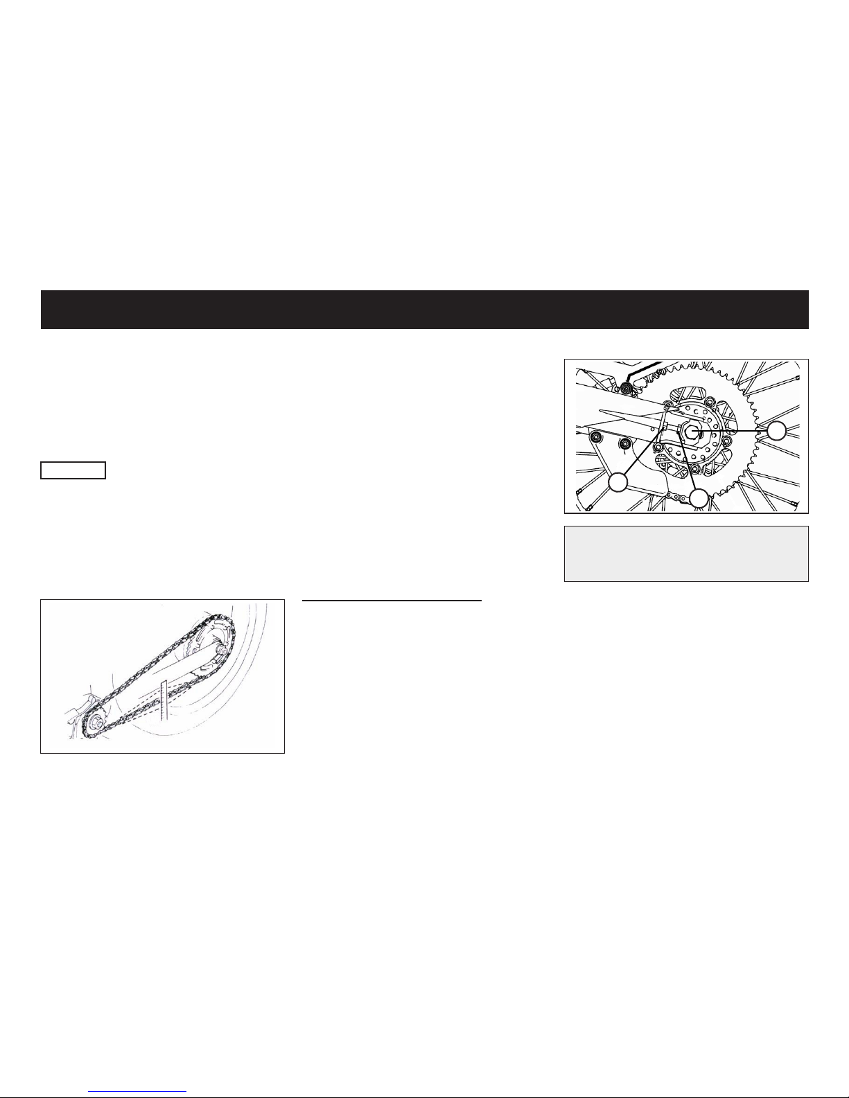
1
3
2
Tightening torque of the collor nut
(1): 70 Nm
SHOCK ABSORBER
Press the rear of the vehicle down to
test the function of the rear damper.
Make sure that no pressure is exerted
on the exhaust in order not to damage
it.
The shock absorber can be adjusted
to suit the weight of the driver and the
load.
WHEEL BEARINGS
The front and rear wheel bearings must
be checked at the intervals specied in
the periodic maintenance and lubrication chart.
CAUTION
If there is play in the wheel hub or if the
wheel does not turn smoothly, have a
dealer check the wheel bearings.
DRIVE CHAIN
10-20 mm
If the chain tension is too great, parts
within the secondary power trasmission
(chain, chain sprockets transmission
and rear wheel bearings) will be subjected to unnecessary stress resulting
in early wear and even chain breakage. Too much slack in the chain, on the
other hand, can result chain jumping off
the chain wheels. If this happens the
chain could also block the rear wheel
or damage the engine. In either case
the operator is likely to lose control of
the vehicle.
Tensioning the chain drive
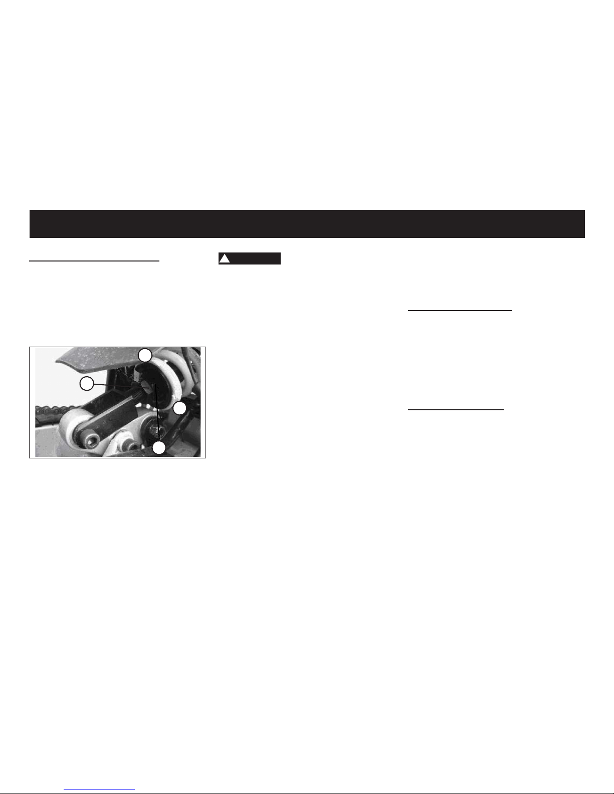
1. Loosen collar nut (1)
2. Loosen counter nut (2)
3. Turn right and left adjusting screws
(3) equally far. The drive chain free
play should be between 10 mm and
20 mm.
4. Tighten counter nut (2) and the collar
nut (1).
40
PERIODIC MAINTENANCE AND MINOR REPAIR
Page 42
!
WARNING
• Do not remove the battery vent seal,
this can be dangerous, the battery
permanently damaged.
• Battery acid is poisonous and dangerous, it contains sulfuric acid and
leads to dangerous burns.
• Avoid skin, eye and clothing contac.
Protect your eyes always when working near the battery.
• Upon contact with the battery aicd,
make immediate FIRST AID.
• If skin or eye contact with battery
acid, rinse the affected areas with
plenty of water.
• When accidentally swallowed battery
acid drink large amounts of water.
• In both cases, as soon as possible,
see a doctor.
• Batteries develop explosive hydro-
gen gas. Keep open ames, smoking
materials away from the battery and
make sure there is adequate ventilation when you charge a battery indoors.
Adjust the shock absorber
Use the nuts (1) and (2) to adjust the
rear shock. Loosen the locknut (1) and
adjust with the help of the nut (2) to adjust the preload of the shock absorber.
Secure the damper then again with the
locknut (1).
1
2
-
+
BATTERY
This model is equipped with a sealedtype (MF) battery, which does not require
any maintenance. There is no need to
check the electrolyte or to add distilled
water.
41
• KEEP THIS AND ALL BATTERIES
OUT OF THE REACH OF CHILDREN.
To charge the battery
Have a dealer charge the battery as
soon as possible if it seems to have discharged. Keep in mind that the battery
tends to discharge more quickly if the
vehicle is equipped with optional electrical accessories.
To store the battery
• If the vehicle will not be used for
more than one month, remove the
battery, fully charge it, and then
place it in a cool, dry place.
• If the battery will be stored for more
than two months, check it at least
once a month and fully charge it if
necessary.
• Fully charge the battery before installation.
• After installation, make sure that the
battery leads are properly connected
to the battery terminals.
PERIODIC MAINTENANCE AND MINOR REPAIR
Page 43
42
!
WARNING
Do not use a fuse of a higher amperage rating than recommended to
avoid causing extensive damage to
the electrical system and possibly a
re.
3. Turn the key to and turn on the
electrical circuits to check if the devices operate.
4. If the fuse immediately blows again,
have a dealer check the electrical
system.
LIGHTING - OPTION 1
Headlight bulbs
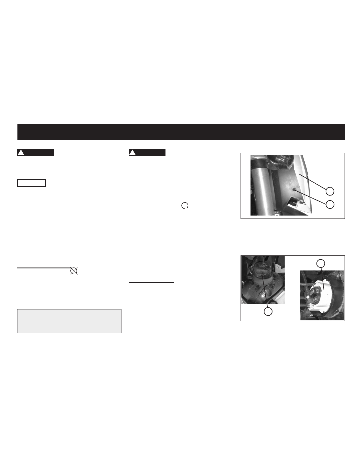
1. If the headlight bulp does not glow,
switch off all consumers and switch
off the engine.
2. Remove the bolts on the left and right
side of the headlight (1).
3. Remove the headlight (2).
!
WARNING
Please contact your dealer if you are
not familiar with handling the battery.
CAUTION
Always keep the battery charged. Storing a discharged battery can cause
permanent battery damage.
FUSE
The fuse holder is located beside battery.
Replacing the fuse
1. Turn the key to and turn off all
electrical circuits.
2. Remove the blown fuse, and then
install a new fuse of the specied
amperage.
Specied fuse:
10 Amp
2
1
4. Take out the rubber dust cover (3).
5. Turn the xing disc anti-clockwise to
take out the the blup (4).
4
3
PERIODIC MAINTENANCE AND MINOR REPAIR
Page 44
43
Front turn signal light
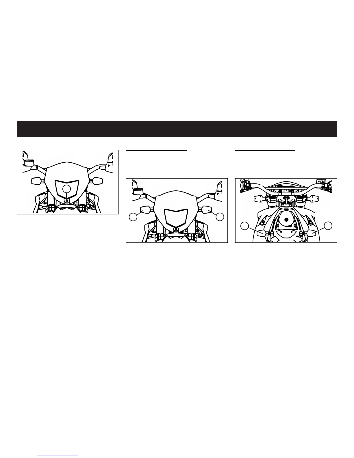
If the turn signal light bulb does not com
on, remove the screw of the indicator
lens (1) out and replace the bulb.
1
1
5
When you need to adjust the headlight
turn in or turn out the adjusting screw
(5).
Rear turn signal light
If the turn signal light bulb does not
com on, remove the screw of the indi-
cator lens (1) out and replace the bulb.
1
1
PERIODIC MAINTENANCE AND MINOR REPAIR
Page 45
44
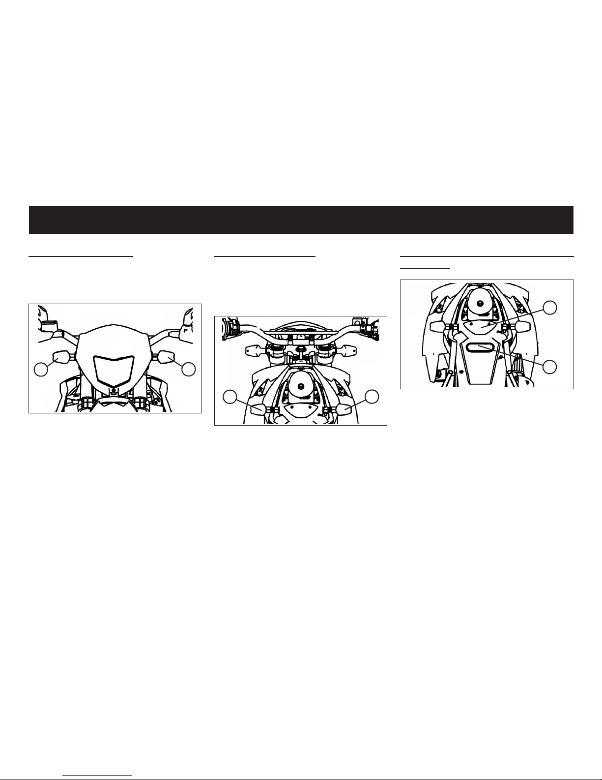
LIGHTING - OPTION 2
Headlight bulbs
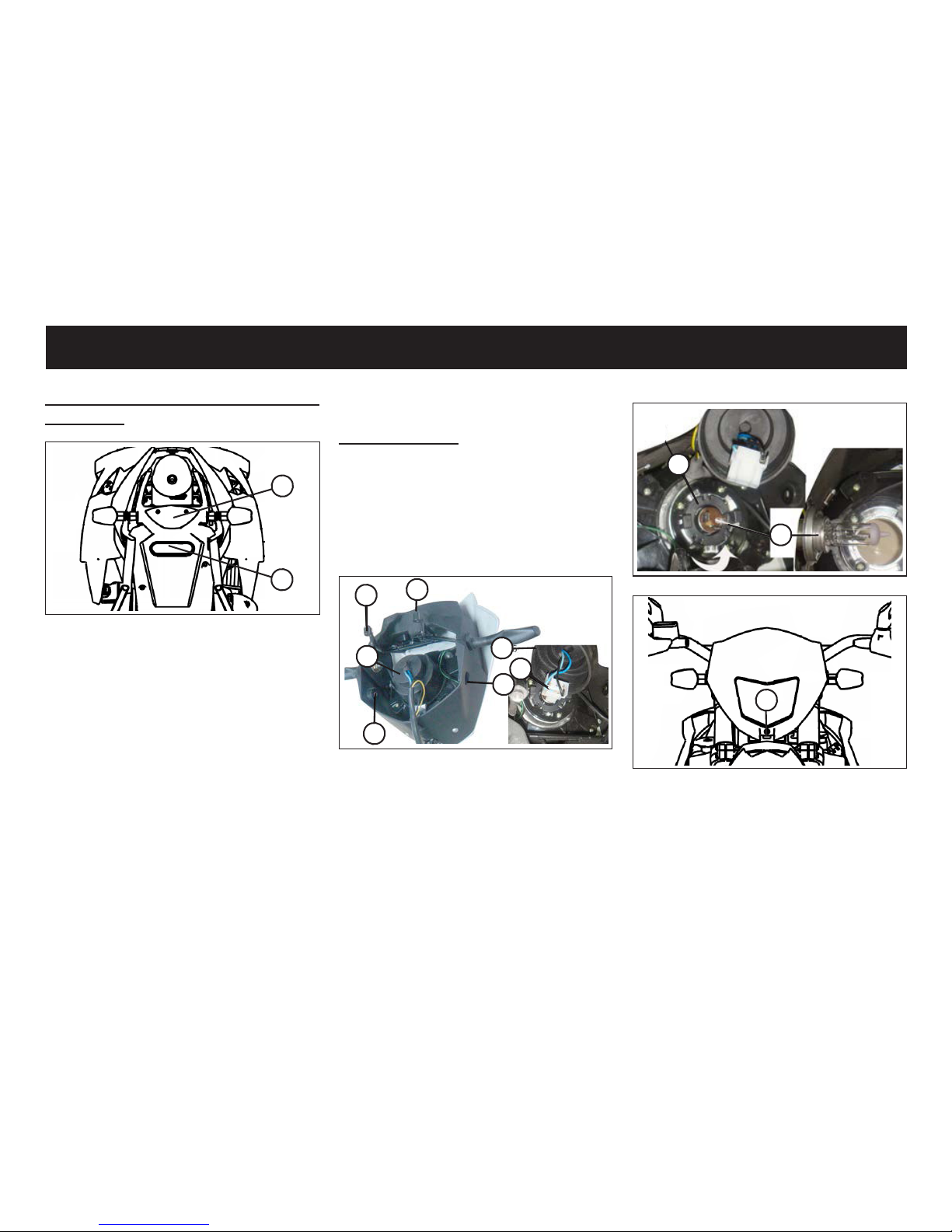
1. If the headlight bulp does not glow
remove the bolts and screws (1 to 4)
to disassemble the head light assembly.
2. Take out the rubber dust cover (5)
and the pug (6).
1
2
5
4
5
6
3
3. Turn the xing disc anti-clockwise to
take out the the blup (7).
Taillight / Brake light and license
plate lamp
2
1
If the tail/brake light (1) or the license
plate light (2) do not glow disassemble
the bolts for changing the bulb.
7
7
8
When you need to adjust the headlight
turn in or turn out the adjusting screw
(8).
PERIODIC MAINTENANCE AND MINOR REPAIR
Page 46
45
Rear turn signal light
If the turn signal light bulb (1) does not
com on, please contact your dealer to
replace it.
1
1
Front turn signal light
If the turn signal light bulb (1) does not
com on, please contact your dealer to
replace it.
1
1
Taillight / Brake light and license
plate lamp
2
1
If the tail/brake light (1) or the license
plate light (2) do not glow disassemble
the bolts for changing the bulb.
PERIODIC MAINTENANCE AND MINOR REPAIR
Page 47

46
TROUBLESHOOTING
Although the vehicles receive a thorough inspection before shipment from the factory, trouble may occur during operation.
Any problem in the fuel, compression, or ignition systems, for example, can cause poor starting and loss of power.
The following troubleshooting chart represents a quick and easy procedure for checking these vital systems yourself.
However, should your vehicle require any repair, take it to a dealer, whose skilled technicians have the necessary tools,
experience, and knowhow to service the vehicle properly.
Use only genuine replacement parts. Imitation parts may look like parts, but they are often inferior have a shorter service
life and can lead to expensive repair bills.
TROUBLESHOOTING
Page 48
47
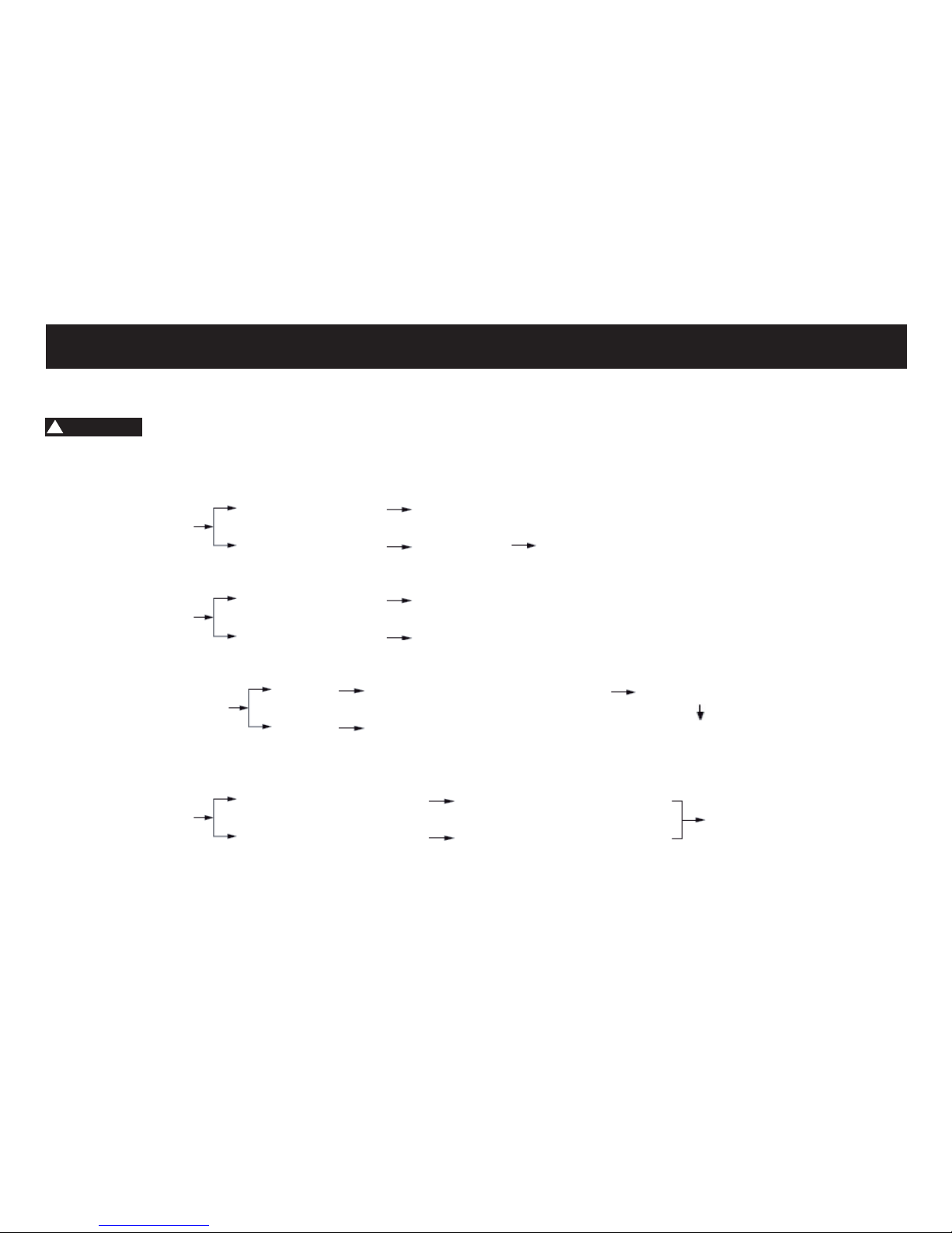
TROUBLESHOOTING CHART
!
WARNUNG
Keep away open ames and do not smoke while checking or working on the fuel system.
TROUBLESHOOTING
1. Fuel
2. Compression
3. Ignition
4. Battery
Check the fuel level in
the fuel tank.
Operate the electric
starter.
Remove the spark plug
and check the electrodes.
Operate the electric
starter.
Operate the electric
starter.
There is no fuel.
There is compression.
There is no compression.
Check the compression.
Supply fuel.
The engine does not start.
Check the compression.
Check the ignition.
Have a dealer check the
vehicle.
Wet
Dry
Wipe off with a dry cloth and correct the
spark plug gaps, or replace the spark
plug.
Have a dealer check the
vehicle.
Operate the electric starter.
The engine does not start.
Check the battery.
The engine turns over quickly.
The engine turns over slowly.
The battery is good.
Check the battery lead connections,
and charge the battery if necessary.
The engine does not start.
Have a dealer check the
vehicle.
Page 49
CLEAN AND STORAGE
48
of the vehicle to prevent damage.
Dry the plastic parts then wipe with a
soft, dry cloth or sponge.
• Protect particularly plastic parts,
paint, headlight glass from harsh
chemicals such as fuel, rust remover,
brake cleaner or similar. The use of
such agents may result in malfunction, damage and affect the security
itself.
• Do not use a high pressure washer
or steam cleaner, causing water
in storage can penetrate electrical
components such as connectors or
switches, lighting, ventilation hoses,
brake shoes and brake linings or
damage, seals, paint and other surfaces.
Cleaning after normal use
Remove dirt with warm water, a mild detergent, and a soft, clean sponge, and
then rinse thoroughly with clean water. Use a toothbrush or bottlebrush for
hard-to-reach areas.
CLEAN THE VEHICLE
Clean of the vehicle in proper and suitable way will make it attractive, extend
it’s lfe and optimize the performance.
Before cleaning
1. Cover the mufer outlet with a plas-
tic bag to prevent water to come . inside. Please do it only after the
2. Closed every caps, covers, electrical connectors that are well install
and water can be avoid to get into,
while you do the clean job.
CAUTION
• Do not use acid-based cleaners. If
such funds used for stubborn stains,
so use this only occasionally, dry it
immediately after and then apply a
corrosion protection spray.
• Always follow the manufacturer‘s
instructions on care and cleaning
agents.
• Use best only water and mild detergent or special cleaner from the
dealer to the sensitive components
Cleaning after riding in the rain,
near the sea or on salt-sprayed
roads
CAUTION
Since sea salt or salt sprayed on the
roads during winter are extremely corrosive in combination with water, carry
out the following steps after each ride.
• Wait until the engine / exhaust have
cooled.
• Clean the vehicle with warm water
and a mild detergent.
• Do not use hot water, which increases the corrosive effect of the salt.
• Apply a corrosion protection spray
on all metal, including chrome- and
nickel-plated, surfaces to prevent
corrosion.
After cleaning
• Dry the vehicle.
• To prevent rust, we recommend appropriate care to use according to
manufacturer‘s instructions.
• Wax all painted surfaces.
Page 50
Recommended Castrol care pro-
ducts:
Greentec Bike Reiniger
Bike Politur
Motorrad DWF oilspray
!
WARNING
• Make sure that there is no oil or wax
on the brakes or tires.
• If necessary, clean the brake discs
and brake linings with a regular brake disc cleaner and wash the tires
with warm water and a mild detergent.
• Before operating the vehicle, test
the braking performance and tires.
STORAGE
Short-term (for a few days)
• Always store your vehicle in a cool,
dry place and, if necessary, protect
it against dust with a vehicle cover.
49
CLEAN AND STORAGE
!
WARNING
Please store the vehicle in a well air
ow room with dry air if possible. A
place with wet humidity will cause rust.
Long-term (for weeks)
• Clean the vehicle.
• Drain the fuel from the carburetor.
• Enter the drained fuel back into the
fuel tank.
• Fill the fuel tank to completely or add
if necessary a fuel stabilizer to protect the fuel tank from rusting and
the fuel from degradation.
Follow the steps below to cylinders,
piston rings, etc. to prevent rusting.
• Remove spark plug cap and the
spark plug.
• Give a teaspoon of engine oil into
the spark plug hole.
• Join the Kickstarter to slow down and
let the engine several times slowly
rotate (thus the cylinder is oiled).
• Put the spark plug back in and put
on the spark plug cap.
!
WARNING
To prevent damage or injury from sparking, make sure to ground the spark
plug electrodes while turning the engine over.
• Lubricate all control cables and the
pivoting points of all levers and pedals as well as of the side stand/
main stand.
• Check and, if necessary, correct the
tire air pressure, and then lift the vehicle so that both of its wheels are
off the ground. Alternatively, turn the
wheels a little every month in order
to prevent the tires from becoming
degraded in one spot.
• Cover the mufer outlet with a plastic bag to prevent moisture from entering it.
• Remove the battery and fully charge
it. Store it in a cool, dry place and
charge it once a month. Do not store
the battery in an excessively cold or
warm place [less than 0 °C (30 °F) or
more than 30°C (90 °F)].
Page 51
ENGINE
Engine type
2-stroke liquid cooled
Cylinder arrangement
Forward-inclined single cylinder
Displacement
49,6 cm 3
Compression ratio
7,0:1
Starting system
Electric starter and kickstarter
Lubrication system
Separate lubrication
2-stroke engine oil
ENGINE OIL
Quantity 1 l
recommended type:
Castrol Power 1 Racing 2T
TRANSMISSION OIL
Type SAE 10W-40
recommended type:
Castrol Power 4T oder ATF Öl
AIR FILTER
Sponge
FUEL
Unleaded gasoline only 95 Oct
Capacity
10 +/- 0,2 l
CAUTION
!! BIOETHANOL FUEL E10 IS NOT PERMITTED !!
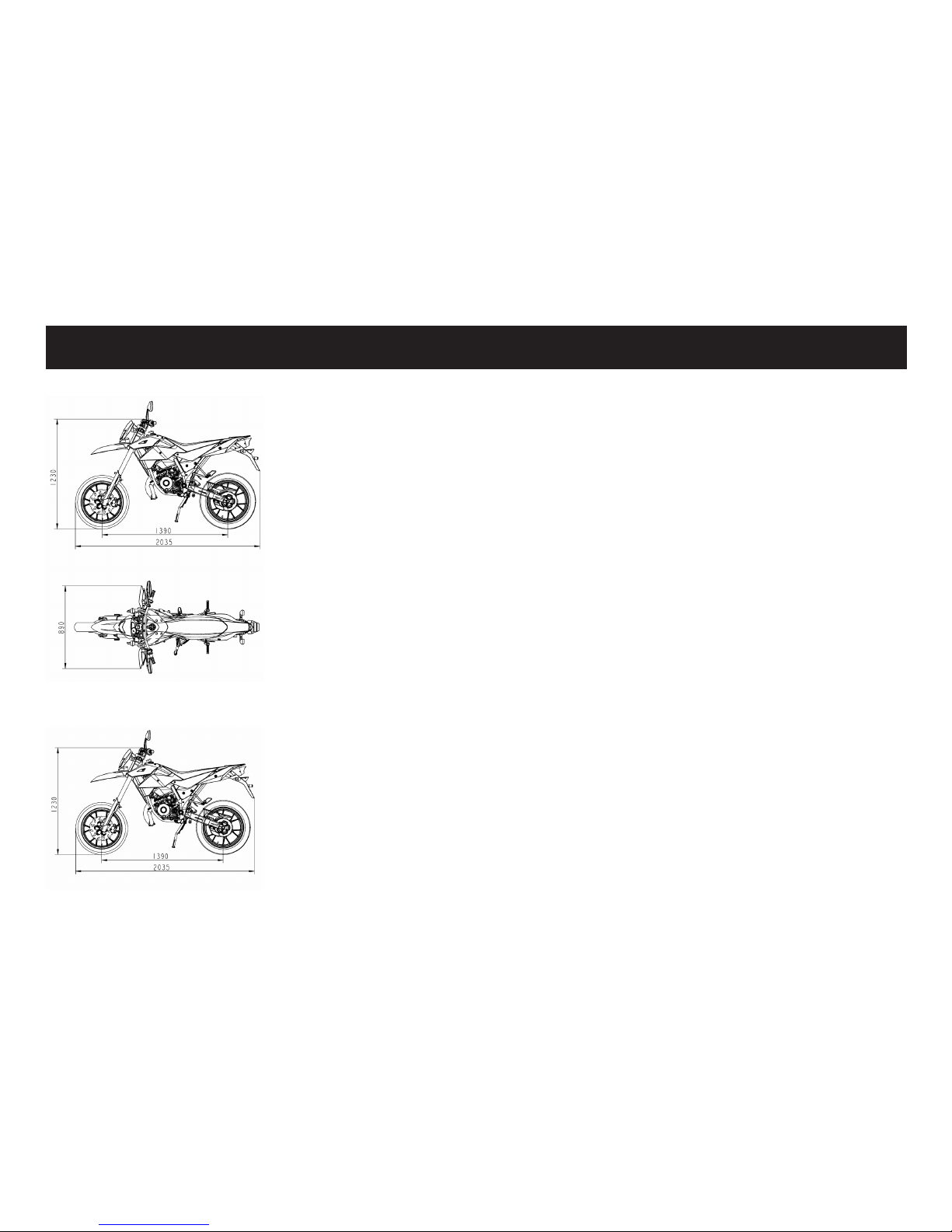
DIMENSIONS - SM MODEL
DIMENSIONS - X MODEL
CARBURETOR
Manufacturer
QJ or LEADER
SPARK PLUG
Manufacturer / model
NGK / BR8ES
Spark plug gap
0,6-0,7 mm
CLUTCH
Clutch type
Multiple plate clutch
Transmission type
6-speed constant mesh transmission
CHASSIS
Frame type
Steel tube backbone
FRONT TIRE - SM MODEL
Rim: 17x2.5
Tyre: 100/80-17
REAR TIRE - SM MODEL
Rim: 17x3.0
Tyre: 130/80-17
FRONT TIRE - X MODEL
Rim: 21x1,6
Tyre: 100/80-17
REAR TIRE - X MODEL
Rim: 18x1,85
Tyre: 130/80-17
SPECIFICATIONS
50
Page 52

51
FRONT SUSPENSION
Type
Telescopic fork
Spring/shock absorber type
Coil spring/oil damper
REAR SUSPENSION
Type
Unit swing
Spring/shock absorber type
Gas/oil damper
ELECTRICAL SYSTEM
Ignition system
CDI
Charging system
CDI magneto
BATTERY
Model
YT4L-BS
Voltage, capacity
12 V, 3 Ah
HEADLIGHT
Halogen bulb
BULB VOLTAGE, WATTAGE X QUANTITY
Headlight
12 V, 35 W/35 W
TIRE AIR PRESSURE (COLD TIRES)
Front: 2,1 bar - 2,5 bar
Rear: 2,1 bar - 2,5 bar
The selected tire pressure depends
on the load!
FRONT BRAKE - SM MODEL
Type
Single Hydraulic disc brake
230 mm
Operation
Right hand
REAR BRAKE - X MODEL
Type
Single Hydraulic disc brake
280 mm
Operation
Right hand
REAR BRAKE
Type
Single Hydraulic disc brake
220 mm
Operation
Right food
RECOMMENDED FLUID
DOT 4 - CASTROL Super Disc
Bremsüssigkeit DOT 4
Tail/brake light
12 V, 5 W/21 W
Front turn signal light
12 V, 10 W or LED
Rear turn signal light
12 V, 10 W or LED
License plate light
12 V, 5 W
Meter lighting
12 V, 2 W
High beam indicator light
12 V, 2 W
Engine oil indicator
12 V, 3 W
Turn signal indicator light
12 V, 3 W
SICHERUNGEN
Hauptsicherung
10 A
SPECIFICATIONS
Page 53
CONSUMER INFORMATION
52
VEHICLE IDENTIFIKATION NUMBER
(VIN)
Please write down the VIN (vehicle identication number) to order replacement
parts from your dealer or the vehicle
should be stolen.
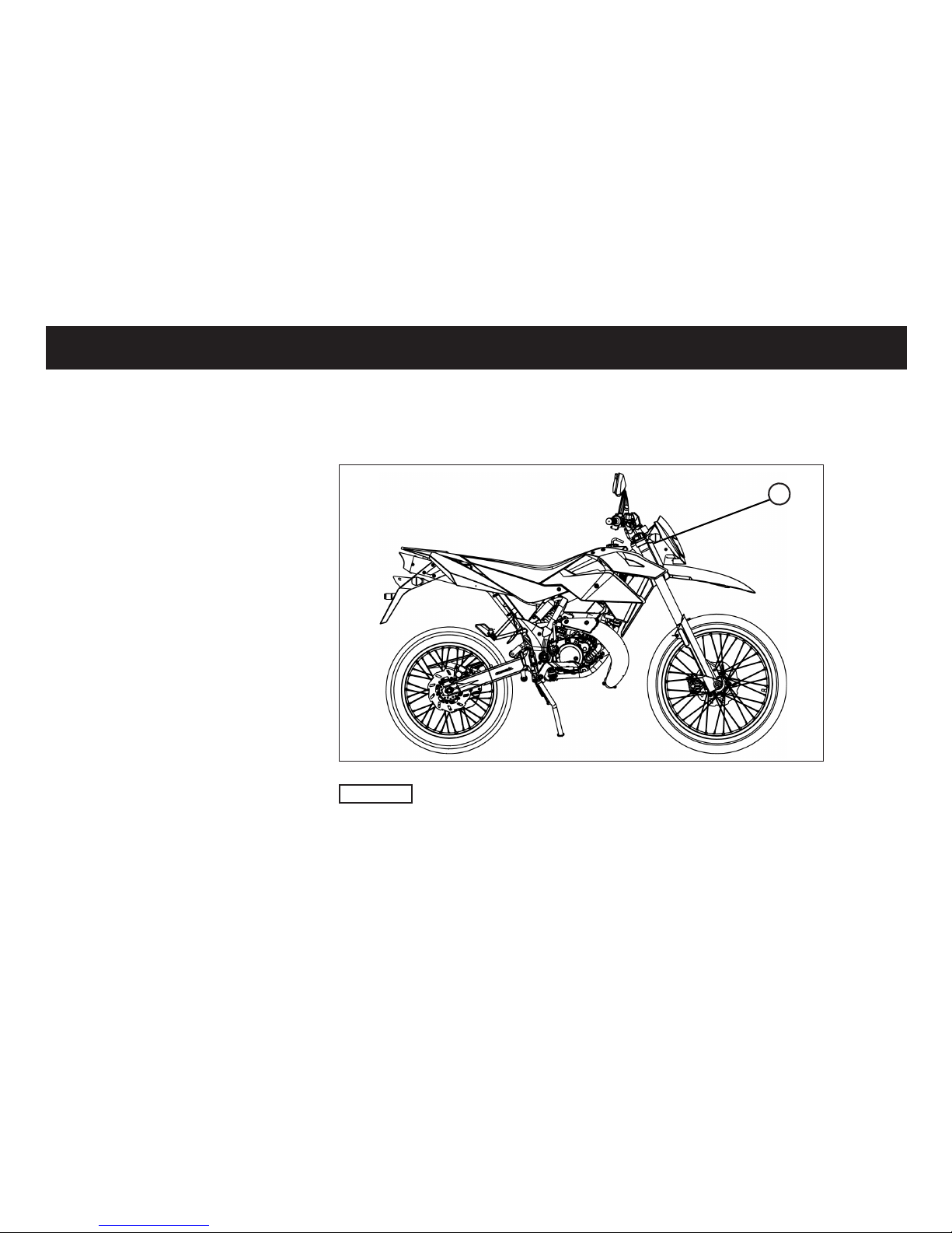
The vehicle identication number of the
vehicle (1) is stamped on the steering
head.
1
CAUTION
The vehicle identication number is used
to identify your motorcycle and may be
used to register your vehicle with the
licensing authority in your area.
Page 54

WARRANTY INFORMATION
53
Please carefully read the instruction manual of your vehicle before operating it in order to make yourself familiar with its handling. We
explicitly point out that the instruction, maintenance, and care instructions given in the operating manual have to be complied with in order
to sustain your claim towards warranty. Only the strict compliance with customer specications stated in the instruction manual ensures
the prolonging of the natural life of your vehicle. Starting with the date of the invoice a limited warranty of 24 months is granted regarding
the accuracy of the vehicle in terms of material and manufacturing according to latest standards. The legal warranty regulations will not
be restricted by this limited guarantee. Maintenance work has to be exclusively done by authorized workshops entitled by us. Warranty in
general is bound to the region of invoicing and can therefore only be carried out within the country the vehicle was bought. Damages that
can be traced back to inappropriate usage, manipulation, or neglecting of the maintenance/care/operating instructions will not be covered
by warranty. Warranty can only be granted if occurring damages are immediately being reported to the seller or any other authorized
workshop by the buyer. The warranty claim entitles the buyer to remedy deciencies or to the reparation respectively the exchange of
a damaged part in an authorized workshop after our approval. Compensation for remote or instantaneous damages cannot be granted.
Vehicles in desolate condition will not be covered by warranty. Repair works carried out on warranty do not enlarge the guarantee period.
Only this document entitles you to call on warranty services. Therefore please make sure that you are delivered this fully lled in document by the seller and that he has registered your vehicle correctly in our system. Please also mind the following advices.
Body and panelling of the vehicle have to be kept free of dirt constantly. Do not use high pressure water blasters, strong jets of water,
sharp and corrosive or other aggressive detergents which could harm surfaces and varnish permanently and foster corrosion. It is vital
to use protecting cleansers. Please consult our dealers for the right and appropriate products. Aluminium parts or other rened parts
(chrome parts, anodized parts or other processed surfaces)have to be treated with appropriate maintenance products in order to prevent
oxidation. Frame and metal parts are continuously to be treated with anticorrosive. A vehicle constantly parked outside has to be covered
to avoid weathering and crack formations on seat and plastic parts. Vehicles used off-road and for racing purposes are excluded from
warranty.
Material which is to be used in the context of service and maintenance works are excluded from warranty as well as the following parts:
incandescent bulbs, brake pads, clutch lining, lter elements, spark plugs, drive sprocket, wheel and axle., as well as the tires.
Page 55
MAINTENANCE SCHEDULE
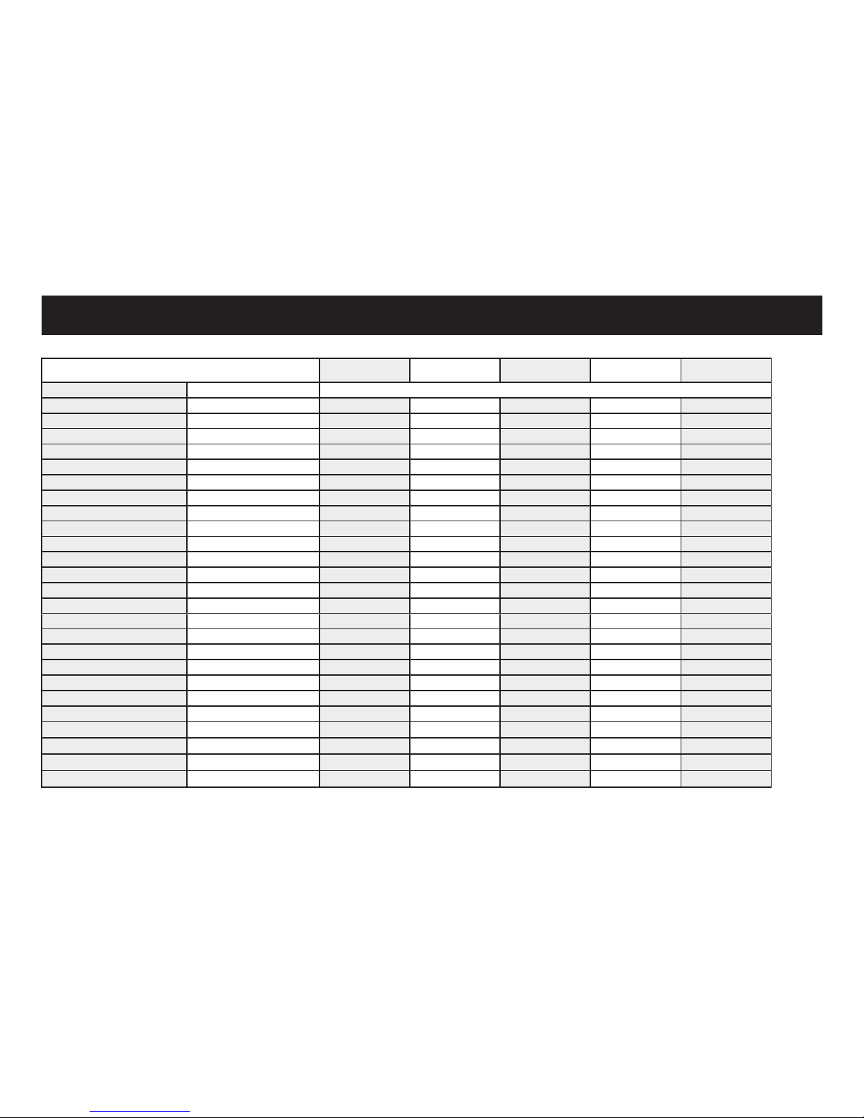
54
The guarantee can be granted only if the vehicle has been serviced in accordance with this maintenance schedule.
CAUTION: Variomatic belt, y wheels respectively drive chain/sproket, spark pluge, fuel lter and air lter element have to be exchanged every 7000km. Only use duration coolant. Brake lines have to be exchanged at least every 4 years. From 13.000km or 24th month the inspection should be made every
7000km. The vehicle is constantly checked for rust. The owner is responsible for rust prevention.
* Model specic deviations are possible
The inspection intervals are required, otherwise, no guarantee can be granted. 1000 km or
1. month
4.000 km or
6. month
7.000 km or
12. month
10.000 km or
18. month
13.000 km or
24. month
PART TO DO
Air lter Clean / exchange √ √ exchange √ √
Wheels, rims Control √ √ √ √ √
Tires Control / tire pressure √ √ √ √
Wheel bearing Control / exchange √ √ √ √
Steering bearing Control / clean / lubricate √ √ √ lubricate √
Screws Coverparts Control / tighten √ √ √ √
Brake system Control / clean / exchange √ √ √ √
Main stand Control / clean / lubricate √ √ √ √
Front fork Control √ √ √ √
Rear suspension Control √ √ √ √
Oil lter Clean √ √ √
Engine oil Control / exchange exchange √ exchange √ exchange
Valves (Engine) Control / adjust √ √ √ √ √
Transmission oil* Exchange exchange exchange exchange
Variomatic belt* Control / exchange √ exchange √
Fly wheels* Control / exchange √ exchange √
Driven chain / sprokets* Control / clean / exchange √ √ √ √ √
Clutch Control √ √ √ √ √
Cable / bowden Control / clean / lubricate √ √ √ √ √
Throttle Control / adjust / lubricate √ √ √ √
Lights / switches Control / adjust √ √ √ √ √
Fuel line / fuel lter Control / exchange
√ exchange √ √
Idle speed Control / adjust
√ √ √ √ √
Exhaust system Control / tighten
√ √ √ √
Coolant* Control
√ √ √ √ √
Page 56
The warranty can be granted only if the vehicle has been serviced in accordance with this service plan.
55
SERVICE PLAN
1000 km or 1. month
Stamp / Signature
4000 km or 6. month
Stamp / Signature
7000 km or 12. month
Stamp / Signature
10000 km or 18. month
Stamp / Signature
13000 km or 24. month
Stamp / Signature
16000 km
Stamp / Signature
19000 km
Stamp / Signature
21000 km
Stamp / Signature
VEHICLE IDENTIFICATION NUMBER:.........................................................................................................................................................................................................................................
MODEL:.................................................................................................................................................................................................................................................................................................................................................................................................
NAME OF THE CUSTOMER:.......................................................................................................................................................................................................................................................................................
SIGNATION OF THE CUSTOMER:............................................................................................................................................................................................................................................................
Page 57
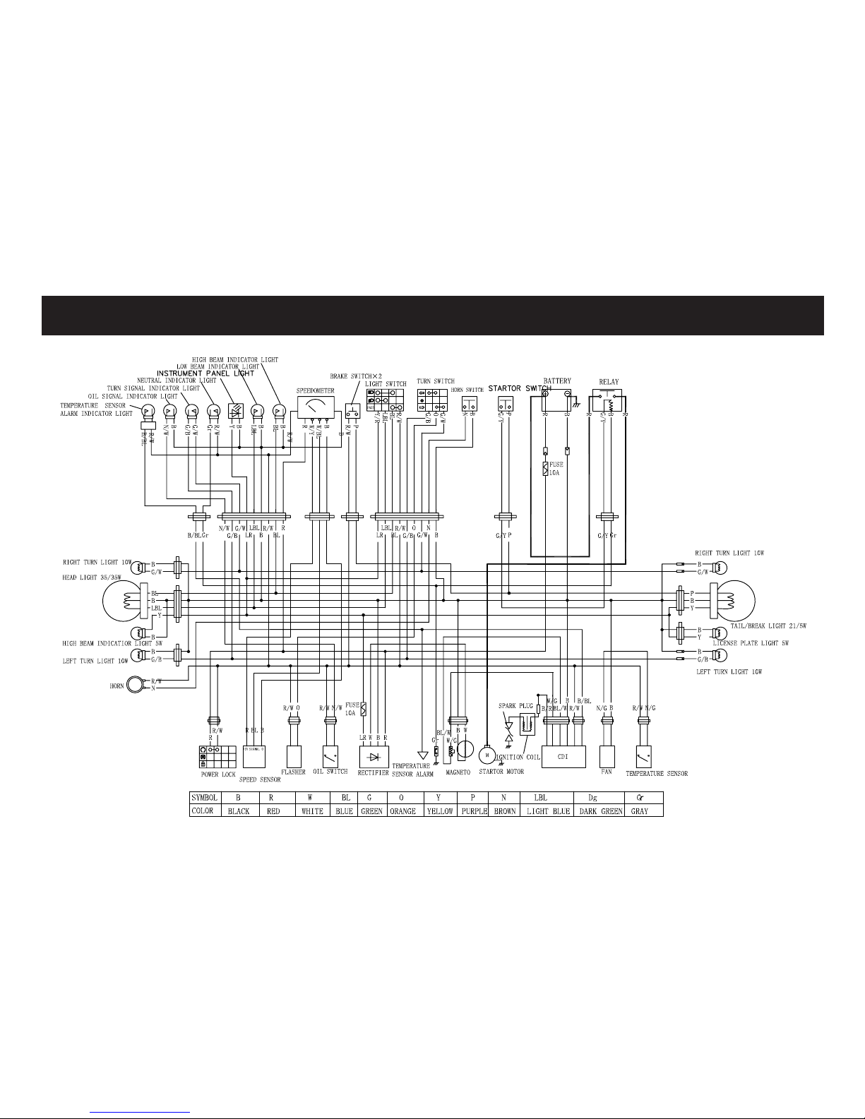
WIRING DIAGRAM
56
Page 58

SPACE FOR NOTES
57
Page 59
 Loading...