


G7603 - Release 3.3

2
CN3200 Access Point - Installation Guide - G7604 - Release 3.3
Product features and specifications are subject to change without prior notice.
xG® and xMax® are registered trademarks of xG Technology, Inc.
All other trademarks used herein are property of their respective owners.
For the latest product documentation and software
updates, please refer to our Web site at
www.xGTechnology.com/support
xG Technology, Inc.
240 South Pineapple Avenue, Suite 701
Sarasota, FL 34236
(941) 953-9035
www.xGTechnology.com

3
CN3200 Access Point - Installation Guide - G7604 - Release 3.3
Table of Contents
Introduction ............................................................................................................... 7
About this Product .................................................................................................................... 7
About this Book ........................................................................................................................ 7
Before You Begin ...................................................................................................................... 7
Hardware Overview .................................................................................................... 8
Powering the CN3200 Modem ................................................................................................. 8
Connectors ................................................................................................................................ 9
Status LED ................................................................................................................................. 9
Important Installation and Safety Notices ................................................................. 10
RF Exposure ............................................................................................................................ 10
FCC Compliance ...................................................................................................................... 11
Before Powering the CN3200 Dual Band Routing Modem ......................................... 12
Configuring the CN3200 Dual Band Routing Modem ................................................. 13
xMax Network Management ................................................................................................. 14
WiFi Network Management ................................................................................................... 15
Connect to the WiFi Access Point .................................................................................................. 16
Antenna Considerations ........................................................................................... 17
Antenna Configuration ........................................................................................................... 18
Installation Preparation ............................................................................................ 19
Assemble Your Parts and Tools .............................................................................................. 19
Equipment Provided in the Standard CN3200 Dual Band Routing Modem Kit ..................... 21
Installation Procedure Overview ............................................................................... 22
Antenna Cabling Identification ............................................................................................... 23
Antenna Orientation Overview .............................................................................................. 24
Antenna Alignment ......................................................................................................................... 24
Antenna Azimuth ............................................................................................................................. 24
Antenna Tilt ..................................................................................................................................... 24
Estimating Installation Times ................................................................................................. 25
Completion and Quality Control Check List ........................................................................... 26
Installation Details .................................................................................................... 27
Antenna Installation and Adjustment Overview .................................................................... 27
Antenna Azimuth Adjustment ......................................................................................................... 27
Mechanical Tilt Adjustment ............................................................................................................ 27
Installation Example ........................................................................................................................ 27
CN3200 Modem / xMax Panel Antenna Assembly ................................................................ 29
Mounting Bracket ............................................................................................................................ 29

4
CN3200 Access Point - Installation Guide - G7604 - Release 3.3
U-Bolts ............................................................................................................................................. 30
2.4 GHz Panel Antenna .................................................................................................................... 30
Installation Procedure ............................................................................................................ 31
Connecting the CN3200 Dual Band Routing Modem to the xMax Network ............... 34
Wired Internet Connectivity and Setting Up a WiFi Hotspot ...................................... 35
Wired Internet Connectivity ................................................................................................... 35
Technical Specifications ............................................................................................ 36
Warranty .................................................................................................................. 37
Limited Warranty .................................................................................................................... 37
SCOPE OF THE WARRANTY .............................................................................................................. 37
ADDITIONAL PROVISIONS OF THE WARRANTY ............................................................................... 38
OBTAINING SERVICE AND SUPPORT UNDER WARRANTY ............................................................... 39
EXCLUSIVITY OF THE WARRANTY .................................................................................................... 39

5
CN3200 Access Point - Installation Guide - G7604 - Release 3.3
List of Figures
Figure 1 — Antenna Configuration ........................................................................................................... 18
Figure 2 — CN3200 Dual Band Routing Modem Parts Checklist .............................................................. 19
Figure 3 — Installation Tool Kit Checklist ................................................................................................. 20

6
CN3200 Access Point - Installation Guide - G7604 - Release 3.3
THIS PAGE INTENTIONALLY LEFT BLANK

7
CN3200 Access Point - Installation Guide - G7604 - Release 3.3
The CN3200 Dual Band Routing Modem is an all-IP, high-capacity and high-performance wireless
access point. It is waterproof and made to handle wide temperature ranges. The CN3200 Modem is
designed for installation in fixed locations such as towers and buildings.
This manual provides basic instructions for installation and configuration of the CN3200 Modem. It
also describes how to connect to the xMax Network and then connect Internet-enabled wireless
devices to the xMax Network.
IMPORTANT
The CN3200 Modem is shipped with the parts needed for basic installation and operation. These
items are shown below. Be sure each of these items is included in your product package. If any item
is missing, please contact the place of purchase.
Depending upon the requirements of your installation, you will also need to purchase additional
components such as cables and surge protectors. A checklist of typically required parts is shown in
the Installation section.
xMax Panel Antenna
and Cables
2.4 GHz Panel Antenna
with Mounting Bracket
and Cable
PoE++ Power Supply
and AC Power Cord
Weatherproof
Ethernet Kit
Ferrite Beads (6)
Installation Bracket
and Hardware

8
CN3200 Access Point - Installation Guide - G7604 - Release 3.3
The CN3200 Dual Band Routing Modem is a compact form-factor base station used for
communicating wirelessly with xMod Mobile Hotspots. The xMax CN3200 Modem is an all-IP, highcapacity, high-performance wireless access point that that delivers wide-area coverage and
reliability, even when there is significant interference.
The CN3200 Modem is totally protected against dust and moisture.
The CN3200 Modem is a Power-over-Ethernet (PoE+) device. The IEEE 802.3at PoE+ standard
enables transmission of both data and the power to operate a device over a single Cat5e cable
connection.
The CN3200 Modem REQUIRES a PoE++ adaptor, as supplied.
The device will NOT operate with a low-power PoE switch or adaptor.
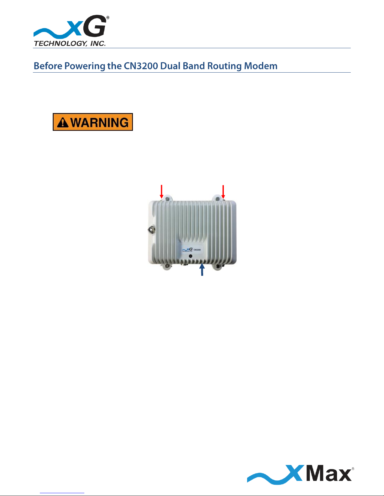
Both top Tx RF ports MUST be properly terminated
before power (PoE) is applied to the unit.
Applying power without proper RF port
termination might damage the unit
and void the product warranty.
Private
Network
110-240
VAC,
50-60 Hz
PoE++
Power Supply
CN3200
DATA OVER
ETHERNET
POWER
plus DATA
TERMINATE
BEFORE
POWER UP

9
CN3200 Access Point - Installation Guide - G7604 - Release 3.3
The CN3200 Modem features seven connectors:
Four external xMax antenna connectors (N-type / female)
A connector for an external 2.4 GHz antenna (TNC-type / female)
A weatherproof Ethernet connector
An unused connector
TOP CONNECTORS
BOTTOM CONNECTORS
Tx 3 Tx 1
Tx/Rx 4
Unused Port
Ethernet
Tx/Rx 2
The CN3200 Modem Status LED indicates power, network status, and hardware fault conditions.
Under normal operating conditions, the LED glows GREEN.
2.4 GHz ANTENNA CONNECTOR
xMax Network
GREEN
SOLID
CONNECTED
RED
SOLID
NOT
CONNECTED
STATUS LED
10
CN3200 Access Point - Installation Guide - G7604 - Release 3.3
These notices apply to the CN3200 Dual Band Routing Modem.
Be sure to read, understand and follow these instructions.
Heed all warnings.
Only use accessories and attachments specified by xG Technology.
Keep a copy of these instructions for future reference.
FCC Part 15 Requirement
The CN3200 Dual Band Routing Modem MUST only be installed by a professional installer. It is the
responsibility of the installer to adjust the transmit power level to ensure that the output power
plus antenna gain does not cause the device to exceed FCC Part 15 output power regulations.
Shielded and grounded Ethernet MUST be used to avoid damage to the CN3200 Modem unit
and ensure proper operation.
Lightning Protection MUST be used on all antenna connections and Ethernet tower runs.
Hazardous situation, which if not avoided,
could result in death or serious injury.
All antennas MUST either be located on the exterior of a vehicle or mounted on a pole.
Every antenna MUST be separated from users by more than 23 cm (0.75 ft) at all times.
This equipment complies with FCC radiation exposure limits set forth for an uncontrolled
environment. This equipment should be installed and operated with minimum distance of
23 cm (0.75 ft) between the radiator and your body. This transmitter must not be co-located
or operating in conjunction with any other antenna or transmitter.
Changes or modifications to this device
not expressly approved by xG Technology
could void the user’s authority to operate the equipment
and void the product warranty.

11
CN3200 Access Point - Installation Guide - G7604 - Release 3.3
NOTE
This equipment has been tested and found to comply with the limits for a Class B digital device,
pursuant to Part 15 of the FCC Rules. These limits are designed to provide reasonable protection
against harmful interference in a residential installation. This equipment generates, uses, and can
radiate radio frequency energy and, if not installed and used in accordance with the instructions,
may cause harmful interference to radio communications. However, there is no guarantee that
interference will not occur in a particular installation. If this equipment does cause harmful
interference to radio or television reception, which can be determined by turning the equipment off
and on, the user is encouraged to try to correct the interference by one or more of the following
measures:
Reorient or relocate the receiving antenna.
Increase the separation between the equipment and receiver.
Connect the equipment into an outlet on a circuit different from that to which the receiver is
connected.
Consult the dealer or an experienced radio technician for help.
12
CN3200 Access Point - Installation Guide - G7604 - Release 3.3
Both top Tx RF ports, MUST be properly terminated
before power (PoE) is applied to the unit.
Applying power without proper RF port
termination might damage the unit
and void the product warranty.
TERMINATE
BEFORE
POWER UP
ETHERNET

13
CN3200 Access Point - Installation Guide - G7604 - Release 3.3
These steps set up the CN3200 Dual Band Routing Modem for use. After completing these
configuration steps, the CN3200 Modem will be fully functional and ready for operation.
The CN3200 modem will provide any Internet-ready device the ability to connect to a public
network via both xMax and WiFi using a hardwired connection to either an Ethernet switch/hub or
an external WiFi hotspot connected through the Ethernet port on the CN3200. The switch/hub or
hotspot is not provided and must be purchased separately.
Devices may also be connected to the xMax network through a wired Ethernet connection to the
CN3200 Modem.
For more information, see Wired Internet Connectivity and Setting Up a WiFi Hotspot on page 35.
NOTES
This procedure should be completed before installing the CN3200 Modem in a service location.
The setup sequence assumes that the CN3200 Modem device is in factory-default
configuration and has not been previously configured.
IMPORTANT: BEFORE YOU CONTINUE
Antennas or dummy loads MUST be connected to the two top Tx RF ports.
The CN3200 Dual Band Routing Modem is powered through the Ethernet cable. PoE (Power-overEthernet) is a standardized system which passes electrical power along with data on Ethernet
cabling.
After terminating the Tx RF ports, connect the provided PoE++ Power Supply, as shown:
DO NOT plug the power cord into the AC outlet until directed.
Private
Network
110-240 VAC,
50-60 Hz
PoE++
Power Supply
DATA OVER
ETHERNET
POWER
plus DATA
CN3200
TERMINATE
BEFORE
POWER UP

14
CN3200 Access Point - Installation Guide - G7604 - Release 3.3
1. Use a laptop or desktop computer to configure the CN3200 Modem.
Ensure that the computer network adapter is configured to Obtain an IP address automatically,
and if DNS servers are static, change the setting to Obtain DNS server addresses automatically.
2. Using an Ethernet cable, connect the computer to the Ethernet connector on the CN3200 Modem.
3. Connect the power cable on the PoE++ Power Supply to a 110 to 240 VAC power source.
The Status LED glows RED within fifteen seconds after the power source is switched on.
NOTE
The CN3200 Modem start up process takes approximately two minutes.
Before continuing, wait until this process completes and the LED glows GREEN.
1. On the computer, open a Web browser.
2. In the browser address line, enter the IP address to open the CN3200 Modem management
window:
CN3200 Modem xMax Network Management
xMax Network IP Address:
https:// 192.168.88.1:8081
3. In the User name and Password fields enter:
User name:
admin
Password:
admin1
The password is case sensitive.
The CN3200 Modem Management window opens to the Status page.
xG Technology strongly recommends that you change the User Password.
4. The menu bar is at the top of the window. To change the User Password, on the right side of the
menu bar, click Admin.
NOTES
The Password is case sensitive.
Before clicking Enter, be sure to write down the new password for future reference:
New Password:

15
CN3200 Access Point - Installation Guide - G7604 - Release 3.3
Enter the User Password, and then click Enter.
The message User password was successfully updated is displayed.
NOTE
DO NOT SET OR USE THE WIFI OPTION WITH THE CN3200 Modem.
5. At the bottom of the page, click Save Changes, and then on the right side of the menu bar,
click Logout to complete the configuration process.
6. Restore the network adapter to its previous settings.
1. In the browser address line, enter the IP address to open the WiFi Network Management window:
CN3200 Modem WiFi Network Management
WiFi Network IP Address:
http://192.168.88.1
2. In the User name and Password fields enter:
User name:
webadmin
Password:
(NULL)
The password is case sensitive.
The first time the interface opens, a warning displays that no password is set.
xG Technology strongly recommends that you create a Password.
3. Click Go to password configuration… in the message box at the top of the window.
Before clicking Save & Apply, be sure to write down the new password for future reference:
NOTE
The password is case sensitive.
New Password:
4. On the Router Password page, enter the new password in the Password field, and then enter it
again in the Confirmation field. Click Save & Apply.
NOTE
To change the password in the future:
On the bar at the top of the window, hover over the Network and then click Administration on the
drop down menu to open the Router Password page.

16
CN3200 Access Point - Installation Guide - G7604 - Release 3.3
Connect to the WiFi Access Point
1. On theTool Bar at the top of the window, hover over Network and then click WiFi on the drop
down menu.
2. On the Wireless Overview page, click Scan.
All available CN1300 WiFi Access Points display in the Associated Stations section.
3. Select a listed WiFi AP by SSID and then click Join Network.
4. On the Join Network: Settings page, enter the passphrase for the WiFi AP in the WPA passphrase
field.
5. In the Name of the new network field, ensure that the value is wwan (lower case).
6. In the Create / Assign firewall-zone section, click to select the wan: radio button,
and then click Submit.
7. On the Wireless Network: Client page, click the General Setup tab in the Device Configuration
section, select the required Transmit Power from the dropdown menu.
8. Click the Advanced Settings tab of the Device Configuration section, and then select the desired
Country Code from the dropdown menu.
9. Continuing in the Wireless Network: Client page, scroll down to the Interface Configuration
section, and then click the Wireless Security tab.
10. Confirm that the displayed Key matches the WPA passphrase set in Step 4.
NOTE
If the passphrase is not visible, click the green reveal toggle icon to the right of the field to display it.
11. Click Save & Apply.
The WiFi network is now available.
IMPORTANT
All other configuration settings must remain unchanged.
Only an advanced user should attempt to adjust any other settings.

17
CN3200 Access Point - Installation Guide - G7604 - Release 3.3
The CN3200 Modem is a 2x4 MIMO device with four antenna connectors — two Tx/Rx and two
Rx-only.
All connectors are always used.
Omni, Panel and Sector antenna configurations are supported.
For optimum performance, the CN3200 Modem should be placed as close as possible to the
antennas.
The antenna cable lengths should be as short as possible.
The GPS antenna can be mounted in any convenient location.
FOR OPTIMUM PERFORMANCE
The cables from the two Tx/Rx connectors on the CN3200 Modem should be connected
to the two antennas on one diagonal.
The cables from the two Rx connectors on the CN3200 Modem should be connected
to the two antennas on the opposite diagonal.
IMPORTANT
UV-resistant CMX outdoor-rated, Cat 5e UTP Ethernet cable MUST be used.
Foil-shielded cable is recommended in areas requiring protection from EMI, RFI, or cross talk.
Failure to properly install the provided IP68-rated Weatherproof Ethernet Power Connector
may lead to product failure, and void the product warranty.
For additional information, please refer to the Antenna Configuration illustration on page 18.

18
CN3200 Access Point - Installation Guide - G7604 - Release 3.3
This is a typical tower-mounted CN3200 Modem installation with a 2x4 MIMO Panel Antenna.
IMPORTANT
Install the provided six (6)
ferrite beads as shown
by this marker
in the wiring diagram.
xMax
ANTENNA
2.4 GHz
ANTENNA
110-240 VAC,
50/60 Hz
PoE++
Power
Supply
PoE
Surge
Protector
ETHERNET
DATA
POWER
plus DATA
xMCC
PoE Surge Protector
Grounded at Building Entry
Figure 1 — Antenna Configuration
Tx/Rx Tx/Rx
1 3
H V
Rx Rx
4 2

19
CN3200 Access Point - Installation Guide - G7604 - Release 3.3
NOTE
xG Technology recommends that the CN3200 Dual Band Routing Modem be configured on a bench
before installing the device in the field. Please refer to the topic Configuring the CN3200 Dual Band
Routing Modem on page 13.
This checklist may assist you in assembling the parts needed to complete the installation.
CN3200 Dual Band Routing Modem
SUPPLIED BY xG Technology
OBTAIN FROM YOUR PART SUPPLIER
CN3200 Modem
with Wall Mount Bracket
UV-resistant CMX outdoor-rated,
Cat 5e UTP Ethernet Cables
(4-6 mm OD; lengths as required)
Weatherproof Ethernet Kit
Data Cable Connectors (RJ45)
PoE++ Power Supply
Grounded PoE Surge Protector
(CTC Union SP-POE-01 or equivalent)
900 MHz Panel Antenna
and 4 Cables (SMA-Female)
2.4 GHz Panel Antenna
and Cable (TNC-Female)
Ferrite Beads
Alternative mounting solution
(as ordered)
Figure 2 — CN3200 Dual Band Routing Modem Parts Checklist
IMPORTANT
The provided weatherproof Ethernet connector requires the use of Ethernet cables with an outside
diameter of 4-6 mm.

20
CN3200 Access Point - Installation Guide - G7604 - Release 3.3
Installation Tool Kit Checklist
8 mm Metric Wrench
10 mm Metric Wrench
11 mm Metric Wrench
Cat 5 Crimp Tool
Digital Inclinometer
or
Magnetic Angle Locator
Magnetic Compass
or
Smart Phone
Compass App
Colored Weatherproof Tape
(if installing multiple units)
Figure 3 — Installation Tool Kit Checklist

21
CN3200 Access Point - Installation Guide - G7604 - Release 3.3
xMax Panel Antenna
and Cables
2.4 GHz Panel Antenna
with Mounting Bracket
and Cable
PoE++ Power Supply
and AC Power Cord
Weatherproof
Ethernet Kit
Ferrite Beads (6)
Installation Bracket
and Hardware
CN3200 Dual Band Routing Modem

22
CN3200 Access Point - Installation Guide - G7604 - Release 3.3
These steps outline the basic tasks required to complete a successful installation at each tower
location. Specific steps will vary, depending upon the requirements of the system design and the
conditions each site.
Details regarding specific steps are found in dedicated topics, as noted.
Optimum network performance can only be achieved through careful planning. Most successful
networks deploy multiple transmission sites, in a triangular overlapping-cell pattern, as shown.
Before beginning the installation steps, the installer should carefully read all of the work orders,
blueprints, plans, datasheets, and site drawings to determine work to be done, and then plan out
the deployment.

23
CN3200 Access Point - Installation Guide - G7604 - Release 3.3
When installing multiple CN3200 Dual Band Routing Modem devices at a site, color code each
sector. Use colored weatherproof tape on each end of each Ethernet cable run, and then record the
azimuth and tilt of each sector.
Refer to the example shown.
Antenna Sector Color Coding
Tower
Sector
Degrees
Azimuth
Degrees
Tilt
Color
1 1 0 0 Red
2 90 0 Blue
3 180 0 Green
4 270 0 Yellow
2 1 0 0 Red
2 45 0 Red-Red
3 90 0 Blue
4 135 0 Blue-Blue
5 180 Green
6 225
Green-Green
7 270 Yellow
8 315
Yellow-Yellow
Single and double striping

24
CN3200 Access Point - Installation Guide - G7604 - Release 3.3
Antenna Alignment
Correct orientation and tilt of the antennas is the most critical part of the installation.
Alignment of the antennas consists of two steps, azimuth orientation (horizontal) and mechanical
tilt adjustment (vertical).
Antenna Azimuth
Azimuth is the horizontal orientation of the antenna on the horizon. The antenna is installed in the
desired azimuth direction.
Compass directions are measured in degrees, with North = 0° (or 360°), East = 90°, South = 180°, and
West = 270°, as shown on the compass rose.
Antenna Tilt
Tilt of the antenna is the vertical angle of the antenna in relation to the horizon. It is also referred to
as elevation or inclination of the antenna.
The angle of elevation is measured in positive or negative degrees, with an angle above the horizon
being positive and below the horizon being negative.
Tilt is used when antenna radiation must be redirected to concentrate the energy in a new
direction. Downward tilt (downtilt) is most common. Inclination up, called uptilt, is very rare and
only used in extreme cases.
Antenna tilt is typically adjusted to zero degrees. The site installation plan indicates any deviation
from the normal zero inclination for each antenna.
25
CN3200 Access Point - Installation Guide - G7604 - Release 3.3
This guide may assist in estimating the time required to complete each xMax CN3200 site
installation.
Every installation has its own unique requirements, specifications, and challenges. The provided
activities and timelines are subjective.
Estimated Installation Times
ACTIVITY
TIME
NOTES
Unpack and inventory CN3200 shipment box
10 minutes
Assemble CN3200 equipment
(CN3200, Antennas, Bracket, Cables)
15 minutes
Mechanical installation of each CN3200
(varies depending upon building or tower installation)
30-60 minutes
Not including climb time
Installation of Cat5 cabling
15-45 minutes
Depending on length and difficulty
Provisioning / programming
15 minutes
Installation of switch
15-30 minutes
Installation of Cat5 surge arrestors
15-30 minutes
Depending on distance from switch
Installation of ground buss for equipment grounding
15-45 minutes
Depending on availability of
existing grounds
Variables
Building and roof access
Use of existing mounts or installation of new mounts
Tower Related Variables
Tower access
Height of equipment to be installed
Type of Cat5 clamping and securing methods
Tower equipment room access
Power locations and availability
Best case scenario for installation of a single CN3200
140 minutes
Any variables will add to this time.

26
CN3200 Access Point - Installation Guide - G7604 - Release 3.3
This checklist may be used to ensure the integrity and quality of the installation during a site
inspection.
Completion and Quality Control Check List
ITEM DESCRIPTION
SATISFACTORY
COMPLETION
NOTES
All equipment installed per site plan
GPS coordinates recorded
Cat 5 installed does not exceed 100 m
Proper materials used
All equipment grounded
All antenna azimuths correct and verified
All antenna tilts correct and verified
All hardware properly tightened
Cable hangers in place
Drip loops in place
Cable stress relief in place
Cat5 cables tested with a cable tester
Each CN3200 properly programmed
Each CN3200 fully tested and operational
Site photos taken and documented
Optional surge arrestors installed
Customer signed off on installation
Signature
Printed Name
Date
Installation Completed By:
Inspected By:
Date:
NOTES:

27
CN3200 Access Point - Installation Guide - G7604 - Release 3.3
These steps outline the basic tasks required to complete a successful installation.
Your specific steps will depend upon the requirements of your system design.
When multiple antennas are installed on the tower, mast, or other support structure, each antenna
is installed at the same height (vertical level), using standard installation practice. On a tower
structure, mount the antennas on a vertical or horizontal member.
Most towers have only three tower legs. When installing four antennas, consider the required
degree separation for the desired coverage. Determine which tower leg will best accommodate two
of the antennas that will not interfere mechanically with the two antennas mounted on the other
two tower legs.
Antenna Azimuth Adjustment
Mount the antenna in the desired azimuth direction, as shown in the site plan.
Use a magnetic compass to determine the optimum mounting location, and then mount the
antenna into place. If a physical compass is not available, a free smart phone compass app can also
be used.
After mounting, again use the compass to ensure that the antenna azimuth is correct. Do not fully
tighten the mount until completing the mechanical tilt adjustment.
Mechanical Tilt Adjustment
Before fully tightening the mounting bolts, measure and adjust the tilt of the antenna with an
inclinometer positioned against the back of the antenna.
Installation Example
After installing the cable, each antenna is then installed and oriented as required by the network
site plan. The rest of the equipment is then installed and connected. This example assumes that the
xMax Network tower is located at 90° (degrees) magnetic in relation to the CN3200 location.
The steps in this example assume that two antennas, one xMax one 2.4 GHz, are to be installed.
1. Install the CN3200 / xMax antenna array.
2. Adjust the azimuth (horizontal orientation) of the antenna to a compass reading of 90° (degrees)
magnetic.
3. Measure and adjust the tilt of the antenna to 0° with an inclinometer positioned against the
back of the antenna. Securely tighten all mounting bolts.
4. Install the 2.4 GHz antenna within 18 inches of the CN3200 mounting location.

28
CN3200 Access Point - Installation Guide - G7604 - Release 3.3
5. Adjust the azimuth (horizontal orientation) of the 2.4 GHz antenna to a compass reading of 90°
magnetic.
6. Measure and adjust the tilt of the antenna to 0° with an inclinometer positioned against the
back of the antenna. Securely tighten all mounting bolts.
7. Complete the remaining installation steps required to connect these components to the power
supply and xMax network, as described in the topic
8. Installation Procedure starting on page 31.

29
CN3200 Access Point - Installation Guide - G7604 - Release 3.3
B A C D D C B
A
These steps outline the basic tasks required to prepare for a successful installation of the CN3200
Dual Band Routing Modem using the two provided panel antennas. These initial steps prepare the
CN3200 for placement in a service location.
1. Locate the supplied mounting bracket and secure the CN3200 Modem to the bracket with
four (4) hex-head screws, as shown.
Mounting Bracket
2. Align the bracket onto the threaded posts on the back of the xMax Panel Antenna
and then secure it with 4 hex-nuts, as shown.
3. Using the photos below, and the wiring diagram in the topic Antenna Configuration on page 18,
as a guide, secure the four supplied cables to the antenna connectors and the CN3200 Modem
connectors.
IMPORTANT
Ensure that the correct Modem connector is attached to the correct antenna connector.
30
CN3200 Access Point - Installation Guide - G7604 - Release 3.3
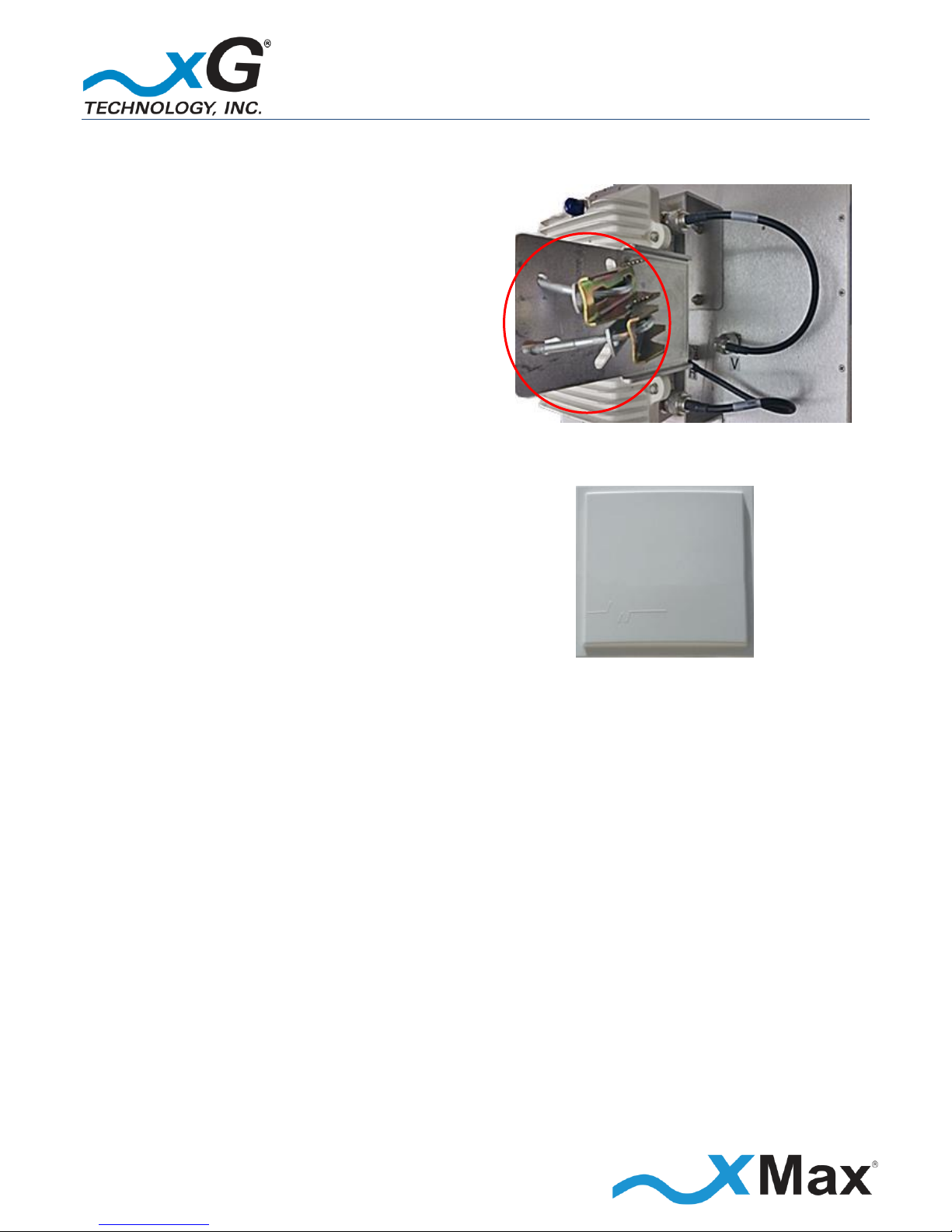
4.
U-Bolts
Locate the two supplied U-bolts,
and then install them onto the
mounting bracket, as shown.
5.
2.4 GHz Panel Antenna
Locate the supplied 2.4 GHz Panel
Antenna and 24 inch cable.
The CN3200 Modem / xMax Panel Antenna array is now prepared for installation.

31
CN3200 Access Point - Installation Guide - G7604 - Release 3.3
NOTE
The CN3200 Modem / Panel Antenna array was previously prepared for installation, as shown in the
topic
CN3200 Modem / xMax Panel Antenna Assembly on page 29.
1. Identify the desired location and height for installation of the CN3200 Modem devices and
antennas to be installed on the structure.
2. At the site location, record the GPS coordinates at the installation location.
3. Install an Ethernet data cable from the CN3200 location to the weather-protected CN3200 PoE
power supply location.
IMPORTANT
To ensure proper operation:
The maximum length of this cable run MUST be less than 100 M (109 yds.)
Outdoor-rated, foil-shielded Ethernet cable (Cat 5e FTP) MUST be used.
Failure to properly install the provided IP68-rated Weatherproof Ethernet Power connector
may lead to failure and void the product warranty.
4. Using the supplied U-bolt mounting bracket, lightly secure the CN3200 Modem / xMax Panel
Antenna assembly to the antenna mast.
5. Orient the antenna towards the xMax Network station, as described in the topic
6. Antenna Orientation Overview on page 24, and then securely tighten the nuts on the U-bolt.
7. In the same manner, using the supplied bracket and hardware, lightly secure the 2.4 GHz Panel
Antenna to the antenna mast.
8. Orient the antenna towards the xMax Network station and then securely tighten the nuts on the
2.4 GHz Panel Antenna U-bolt.
9. Using the supplied cable, attach the cable connector to the 2.4 GHz Panel Antenna, and then attach
the other end of the cable to the top connector on the CN3200 Modem.
10. Attach the supplied weatherproof Ethernet connector onto the CN3200 end of the data cable.
11. Attach two of the supplied ferrite cores to the CN3200 end of the Ethernet cable, as shown in the
wiring diagram in the topic Antenna Configuration on page 18.
12. Attach the cable with the weatherproof Ethernet connector to the connector on the mounted
CN3200 Modem.
Install appropriate ground lightning protection.

32
CN3200 Access Point - Installation Guide - G7604 - Release 3.3
Check the antenna positioning to ensure that the specified azimuths and tilts are correct, and
readjust as necessary.
Inspect the completed work to ensure all hardware is tight, antennas are level, hangers are properly
fastened, proper support is in place, and strain reliefs and drip loops are provided on all exposed
cables.
IMPORTANT NOTICE
All connectors on the CN1100 Access Point are IP67-rated, providing full protection against dust and
water intrusion. Application of any additional weatherproofing is NOT required.
If weatherproofing products are used, future servicing of the equipment might be difficult or
impossible, and void the product warranty.
Complete the remainder of the installation at the indoor CN3200 PoE power supply location.
13. At the end of the Ethernet cable running from the location where the CN3200 Modem and
antennas are installed, install a PoE Surge Protector at the location where the cable enters the
building.
IMPORTANT
The PoE Surge Protector MUST be properly grounded.
14. Attach two ferrite cores to the PoE Surge Protector end of the Ethernet cable, as shown in the
wiring diagram in the topic Antenna Configuration on page 18.
15. Secure the Ethernet cable to the grounded PoE Surge Protector.
16. Install the supplied PoE++ Power Supply near the PoE Surge Protector.
17. Using a short Ethernet cable, connect the PoE Surge Protector to the Power plus Data (OUT) port
on the PoE++ Power Supply.
18. Prepare an Ethernet cable to connect the PoE++ Power Supply to the xMax network:
Attach two ferrite cores to the power supply end of the Ethernet cable, within 6 inches of the
PoE++ Power Supply, as shown in the wiring diagram in the topic Antenna Configuration on
page 18.
19. Connect the Ethernet cable from the xMax network to the Data (IN) port on the
PoE++ Power Supply.
This completes the physical installation of the CN3200 Dual Band Routing Modem.

33
CN3200 Access Point - Installation Guide - G7604 - Release 3.3
20. Connect the supplied AC Power Cord to the PoE++ Power Supply.
21. Ensure that all connections are correct, and then plug the AC Power Cord into a 110 VAC power
source.
Within approximately three minutes, the CN3200 Modem initializes and begins broadcasting
beacons.
At this time the Status LED glows GREEN. If backhaul is not available, the Status LED glows RED.
22. Test the operation of all transmission components, using a Cat5 tester, or xMax xDrive software.
Refer to the xDrive User Guide for instructions.
23. Document the installation with site photos of the completed work performed. In multiple CN3200
Dual Band Routing Modem device installations, be sure to record the device cable color-code and
azimuth for each sector.

34
CN3200 Access Point - Installation Guide - G7604 - Release 3.3
IMPORTANT
Before you begin this step, it is assumed that the CN3200 Dual Band Routing Modem has been
configured as described in the steps shown in the topic Configuring the CN3200 Dual Band Routing
Modem on page 13.
These steps connect the CN3200 Modem to an xMax network.
Connect the power cable on the PoE++ Power Supply to a 110 to 240 VAC power source.
Within 15 seconds after the power source is applied, the Status LED glows RED.
If the CN3200 Modem is within range of an xMax Network, it connects within 2 minutes and the LED
glows GREEN.
The CN3200 Dual Band Routing Modem is now fully functional.
NOTES
If the Status LED remains RED after two minutes have elapsed,
ensure that the CN3200 Modem is within range of an operating xMax Network.
If the CN3200 Modem is within range of an operating xMax Network, but not connecting,
follow these steps to restart the CN3200 Modem:
Power off the CN3200 Modem.
Wait 60 seconds.
Power on the CN3200 Modem.
35
CN3200 Access Point - Installation Guide - G7604 - Release 3.3
A properly configured device, such as a PC or laptop computer, can be wired directly to the
CN3200 Dual Band Routing Modem for Internet access.
1. Configure the device network interface for DHCP operation.
2. Using an Ethernet cable, connect the device to the CN3200 Dual Band Routing Modem.
The CN3200 Modem can be used to create a WiFi hotspot.
3. Using an Ethernet cable, connect a WiFi router to the CN3200 Modem.
4. Configure the WiFi router according to the manufacturer instructions.

36
CN3200 Access Point - Installation Guide - G7604 - Release 3.3
xMax RADIO
Tx Power Output AVG:
RANGE: 24 dBm in 1 dB steps; (BPSK, QPSK, QAM 16/64)
Receiver Sensitivity
-100 dBm BPSK/-90 dBm QAM64
2.4 GHz RADIO
Operating Parameters:
8.5 to 24 dBm, sensitivity @ -92 db; Total throughput rated at 150
SYSTEM OVERVIEW
Frequency Band:
902-928 MHz
Channel size:
1.44 MHz
Modulation:
Adaptive BPSK / QPSK / QAM16 / QAM64
Spectral Efficiency:
Up to 4.25 Bits/Hz
PHY Protocol:
Proprietary OFDM, 2x4 MIMO
Mobility:
Up to 100 MPH
Raw Data Rate :
Up to 6 Mbps
RADIO PERFORMANCE
Tx Power Output AVG:
RANGE: 27 dBm in 1 dB steps
Receiver Sensitivity:
-100 dBm BPSK/-90 dBm QAM64
ANTENNA
Four N-type female connectors (xMax), one TNC female (2.4 GHz)
POWER
PoE++ (Power over Ethernet Plus)
PHYSICAL DESCRIPTION
Size:
8.5” x 7.5” x 3.5” (21.59 cm x 19.05 cm x 8.89 cm)
Weight:
5 lbs (2.27 kg)
ENVIRONMENTAL
Operating Temp:
-40° F to 122° F (-40° to 50° C)
Water/Dust:
IP67
Humidity:
0-100% condensing
ESD:
ESD ±30 kV
REGULATORY
EMC:
FCC CFR 47 Part 15 Class B
Vibration and Shock:
MIL-STD 810F Method 514.5 Vibration (constant acceleration), MIL-STD
MANAGEMENT
NMS:
xMonitor® Proprietary Event/Fault Manager
SNMP v2 Management

37
CN3200 Access Point - Installation Guide - G7604 - Release 3.3
CN3200 Dual Band Routing Modem
xG Technology, Inc. (“xG”)
240 South Pineapple Avenue, Suite 701
Sarasota, FL 34236
SCOPE OF THE WARRANTY
Unless a different period is specified for a particular hardware Product, or in a sales agreement
between xG and customer, or in the published specification sheet for the hardware Product, xG's
hardware Products are generally warranted against defects in workmanship and materials for a
period of twelve (12) months from the date of original purchase, provided the Product remains
unmodified and is operated under normal and proper conditions. Unless otherwise so provided the
warranty period for computer programs in machine-readable form included in a hardware Product,
which are essential for the functionality will be coincident with the warranty period of the
hardware Product. Software patches, bug fixes or workarounds do not extend the original warranty
period. For Software sold by xG and run outside the hardware Product (e.g. xMSC), the warranty
term is 90 days from date of original purchase. All accessories (e.g. antennas, cables, power supply,
POE) carry a warranty term of 90 days from date of original purchase.
The Limited Warranty extends only to the original purchaser of the Product from xG, or its
authorized Resellers, and is not assignable or transferable to any subsequent purchaser or enduser.
xG’s warranty applies only to a Product that is manufactured by or for xG Technology and is
identified within xG’s price book at time of purchase . Any products not covered by xG’s warranty,
but supplied under the customer's Purchase Order with xG as part of the delivered equipment, are
covered under that manufacturer's standard warranty and any warranty claims should be handled
directly with that manufacturer.
xG’s warranty shall not apply: (i) to any Product subjected to accident, misuse, neglect, alteration,
acts of God, improper handling, improper transport, improper storage, improper use or application,
improper installation, improper testing or unauthorized repair; (ii) use of parts or accessories not
approved or supplied by xG, or failure to perform operator handling and scheduled maintenance
instructions supplied by xG or (iii) to cosmetic problems or defects that result from normal wear
and tear under ordinary use, and do not affect the performance or use of the Product.
If the Product develops a covered defect within the warranty period, xG will, at its option, either
repair or replace the Product found by xG to be defective or not in conformity with material
specifications, provided that the Product is returned during the warranty period.

38
CN3200 Access Point - Installation Guide - G7604 - Release 3.3
Customer is responsible for shipment to xG (or authorized service provider) and assumes all costs
and risks associated with this transportation; return shipment to the Customer will be at xG’s
expense. Customer shall be responsible for return shipment charges for Product returned where xG
determines there is no defect ("No Defect Found"), or for Product returned that xG determines is
not eligible for warranty repair. No charge will be made to customer for replacement parts for
warranty repairs.
Product that has been repaired or replaced may consist of refurbished equipment that contains
used components, some of which have been reprocessed. The used components comply with xG
Product performance and reliability specifications. The repair services provided are warranted
against defects in workmanship and materials on the repaired component of the product for a
period of 30 days from the shipment date of the repaired product, or until the end of the original
warranty period, whichever is longer.
xG is not responsible for any damage to or loss of any software programs, data or removable data
storage media, or the restoration or reinstallation of any software programs or data other than the
software, if any, installed by xG during manufacture of the Product or shipped with Product. xG’s
sole obligation for software that when properly installed and used does not substantially conform
to the published specifications in effect when the software is first shipped by xG, is to use
commercially reasonable efforts to correct any reproducible material non conformity (as
determined by xG at its sole discretion) by providing Customer with: (a) telephone or e-mail access
to report non conformance so that xG can verify reproducibility; (b) a software patch or bug-fix, if
available, or a workaround to bypass the issue, if available; and (c) where applicable, replacement
of damaged or defective external media, such as a CD-ROM disk, on which the software was
originally delivered. xG does not warrant that the use of the software will be uninterrupted, error-
free, free of security vulnerabilities, or that the software will meet Customer’s particular
requirements. Customer’s sole and exclusive remedy for breach of this warranty is, at Seller's
option, to receive (i) suitably modified software, or part thereof, or (ii) comparable replacement
software or part thereof.
ADDITIONAL PROVISIONS OF THE WARRANTY
Because it is impossible for xG to know the purposes for which the purchaser acquired this Product
or the uses to which this Product will be put, the purchaser assumes full responsibility for the
selection of the Product for its installation and use. While every reasonable effort has been made
to insure that the purchaser will receive a Product that can be used and enjoyed, xG does not
warrant that the functions of the Product will meet the purchaser’s requirements or that the
operation of the Product will be uninterrupted or error-free. xG is not responsible for problems
caused by the interaction of the Product with any other software or hardware.

39
CN3200 Access Point - Installation Guide - G7604 - Release 3.3
OBTAINING SERVICE AND SUPPORT UNDER WARRANTY
To obtain warranty service or technical support, please contact the party from whom you
purchased the product. If you purchased the product directly from xG, contact your xG Sales
Representative or call 754-206-4800. To take advantage of this Limited Warranty Purchasers are
required to supply an original point of purchase receipt. Returned Product must be accompanied by
the purchaser’s sales receipt or comparable substitute proof of sale showing the date of purchase,
the serial number of Product, and the sellers’ name and address (if purchased through a authorized
xG reseller).
EXCLUSIVITY OF THE WARRANTY
This Limited Warranty Policy shall be the sole and exclusive remedy of the purchaser with respect
to xG’s Products. xG's sole liability on any claim arising out of the sale of the Product or xG's
replacement of defective product, whether in contract, warranty, tort, or otherwise shall be limited
to the purchase price of the goods that prove defective or nonconforming. In no event shall xG be
liable for, and purchaser shall hold xG harmless from, any damages, direct, indirect, or
consequential, whether resulting from xG's negligence or otherwise, arising out of, in connection
with, or resulting from the goods sold to the Purchaser (including, without limitation, damages, for
loss of business profits, business interruption, loss of information, or any other pecuniary loss), and
any and all claims, actions, suits, and proceedings which may be instituted in respect to the
foregoing, including those made by subsequent owners and users of the goods. In no event shall xG
be liable for damages from alleged negligence, breach of warranty, strict liability, incidental or
consequential damages, or any other theory, other than the Limited Warranty set forth herein.
xG neither assumes nor authorizes any of its dealers, representatives, or any other person or entity
to assume for it any other obligation or liability beyond that which is expressly provided for in this
Limited Warranty.
xG MAKES NO WARRANTY OTHER THAN THE LIMITED WARRANTY REFERRED TO HEREIN. THIS
LIMITED WARRANTY IS EXPRESSLY IN LIEU OF ANY AND ALL OTHER EXPRESS OR IMPLIED
WARRANTIES, INCLUDING ANY IMPLIED WARRANTY OF MERCHANTABILITY OR FITNESS FOR A
PARTICULAR PURPOSE, AND IT CONSTITUTES THE ONLY WARRANTY MADE WITH RESPECT TO THE
GOODS COVERED BY THESE TERMS AND CONDITIONS. xG SHALL UNDER NO CIRCUMSTANCES BE
LIABLE FOR ANY INCIDENTAL OR CONSEQUENTIAL DAMAGES.

G7603 - Release 3.3
© Copyright xG Technology, Inc. 2015. All Rights Reserved.
xG Technology, Inc.
240 South Pineapple Avenue, Suite 701
Sarasota, FL 34236
(941) 953-9035
www.xGTechnology.com
 Loading...