


Certification Exhibit
FCC ID: VEYXVMR1
FCC Rule Part: 15.247
ACS Project: 15-2067
Manufacturer: xG Technology, Inc.
Model: CN3100
User Manual
3998 FAU Blvd. Suite 310 Boca Raton, FL 33431 Tel: 561-961-5585 Fax: 561-961-5587
G7609 - Release 3.0 - DRAFT
For xG Technology Internal Review Only!
2
CN3100 Vehicle Modem - Installation Guide - G7609 - 3.0 - DRAFT
Product features and specifications are subject to change without prior notice.
xG® and xMax® are registered trademarks of xG Technology, Inc.
All other trademarks used herein are property of their respective owners.
For the latest product documentation and software
updates, please refer to our Web site at
www.xGTechnology.com/support
xG Technology, Inc.
240 South Pineapple Avenue, Suite 701
Sarasota, FL 34236
(941) 953-9035
www.xGTechnology.com
For xG Technology Internal Review Only!
DRAFT
3
CN3100 Vehicle Modem - Installation Guide - G7609 - 3.0 - DRAFT
Table of Contents
Introduction ............................................................................................................... 5
About this Product .................................................................................................................... 5
About this Book ........................................................................................................................ 5
Before You Begin ...................................................................................................................... 5
Hardware Overview .................................................................................................... 6
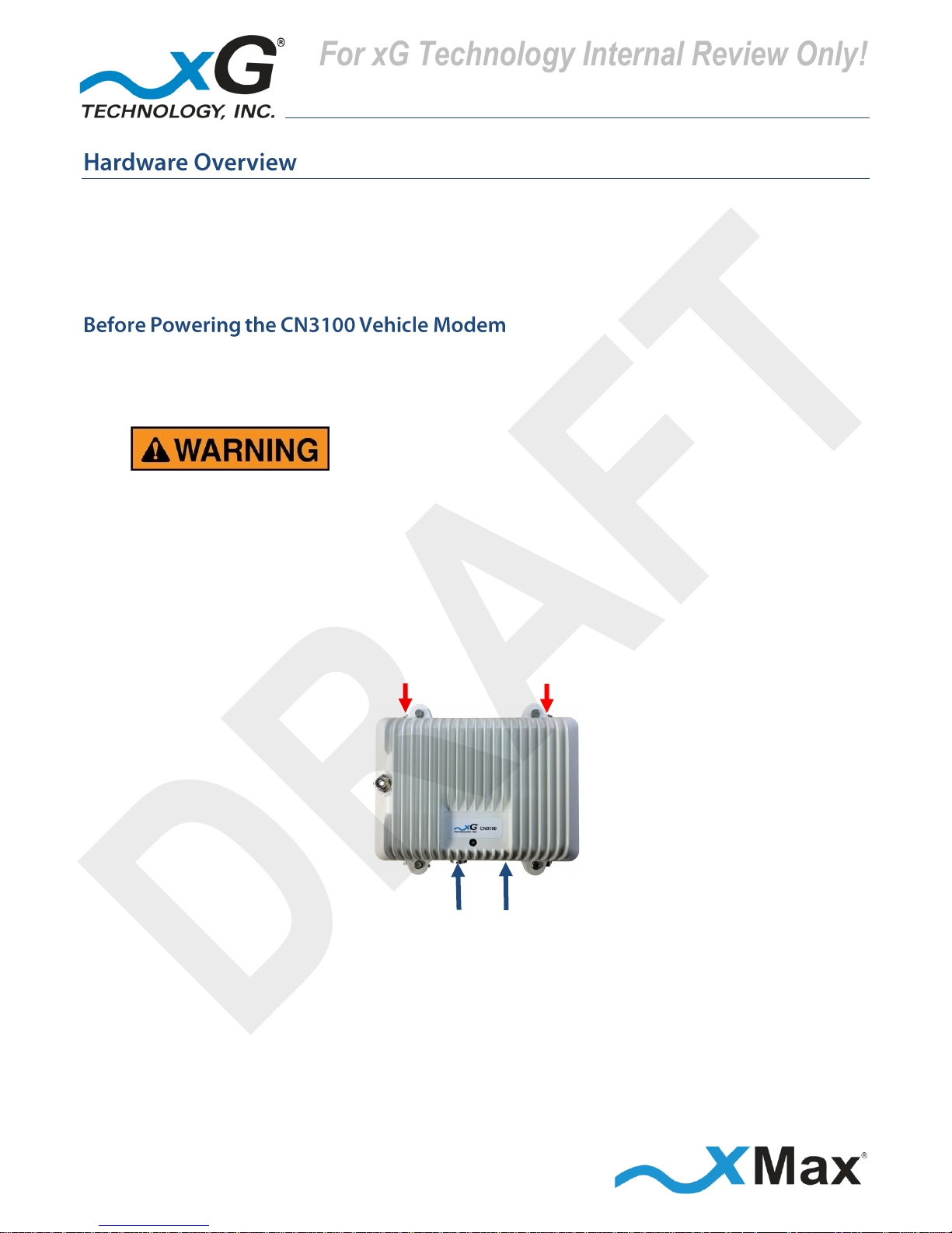
Before Powering the CN3100 Vehicle Modem ........................................................................ 6
Connectors ................................................................................................................................ 7
Status LED ................................................................................................................................. 7
Important Safety and Installation Requirements ........................................................ 8
FCC Part 15 Requirement ......................................................................................................... 8
Hazard ....................................................................................................................................... 8
FCC Compliance ........................................................................................................................ 8
RF Exposure .............................................................................................................................. 9
Antenna Considerations ........................................................................................... 10
Antenna Configurations ............................................................................................ 11
Omni Antenna Configuration ................................................................................................. 11
xMax Dual-polarity Vehicle Antenna Configuration .............................................................. 11
Omni Configuration Connections ........................................................................................... 12
xMax Dual-polarity Vehicle Antenna Configuration Connections ......................................... 13
Configuring the CN3100 Vehicle Modem ................................................................... 14
Installation ............................................................................................................... 18
Assemble Your Parts and Tools .............................................................................................. 18
Installation Procedure ............................................................................................................ 19
Connecting Wireless Devices to the xMax Network .................................................. 20
Wired Internet Connectivity ................................................................................................... 20
CN3100 Vehicle Modem Management Tool .............................................................. 21
Overview ................................................................................................................................. 21
Content and Functions Chart .......................................................................................................... 23
CN3100 Vehicle Modem Management Details ...................................................................... 24
Home View ...................................................................................................................................... 24
Information View – Home ............................................................................................................... 24
Information View – xMax ................................................................................................................ 25
Information View – WiFi.................................................................................................................. 25
Information View – System Information ......................................................................................... 26
For xG Technology Internal Review Only!
DRAFT

4
CN3100 Vehicle Modem - Installation Guide - G7609 - 3.0 - DRAFT
Information View – Tools ................................................................................................................ 26
Settings View – WiFi ........................................................................................................................ 27
Settings View – xMax ...................................................................................................................... 27
Settings View – Other ...................................................................................................................... 28
Logs View ......................................................................................................................................... 28
Accounts View ................................................................................................................................. 29
Upgrade View .................................................................................................................................. 29
Technical Specifications ............................................................................................ 30
Warranty .................................................................................................................. 31
Limited Warranty .................................................................................................................... 31
SCOPE OF THE WARRANTY .............................................................................................................. 31
ADDITIONAL PROVISIONS OF THE WARRANTY ............................................................................... 32
OBTAINING SERVICE AND SUPPORT UNDER WARRANTY ............................................................... 33
EXCLUSIVITY OF THE WARRANTY .................................................................................................... 33
For xG Technology Internal Review Only!
DRAFT
5
CN3100 Vehicle Modem - Installation Guide - G7609 - 3.0 - DRAFT
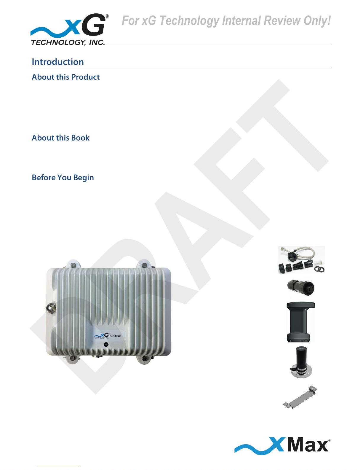
The CN3100 Vehicle Modem is a ruggedized subscriber device. It is waterproof and made to handle
wide temperature ranges. While primarily designed for vehicle usage, the device may be used in fixed
locations, such as in parks or at outdoor events.
It enables any Internet-ready device to connect to the xMax network, either wirelessly using secure
WiFi links or through a wired Ethernet connection.
This manual provides basic instructions for installation and configuration of the CN3100 Vehicle
Modem. It also describes how to connect to the xMax Network and then connect Internet-enabled
wireless devices to the xMax Network.
IMPORTANT
The CN3100 Vehicle Modem is shipped with the parts needed for installation and operation.
Be sure each of these items is included in your product package. If any item is missing, please contact
the place of purchase.
Depending upon the requirements of your installation, you may also need to purchase additional
components such as fuses and cables. A checklist of typically required parts is shown in the topic
Weatherproof
Ethernet Kit
Weatherproof Power
Connector
with 3 ft. cable
xMax Antenna with
Magnetic Mount
Magnetic Mount
WiFi Antenna
CN3100 Vehicle Modem
Mounting
Bracket
For xG Technology Internal Review Only!
DRAFT
6
CN3100 Vehicle Modem - Installation Guide - G7609 - 3.0 - DRAFT
The CN3100 Vehicle Modem is a self-contained IEEE 802.11b/g access point and xMax modem.
It is a full-featured hotspot allowing connection by up to 5 users.
The CN3100 is totally protected against dust and moisture.
Both top Tx RF ports, MUST be properly terminated
before power is applied to the unit.
Applying power without proper RF port
termination might damage the unit
and void the product warranty.
POWER
ETHERNET
TERMINATE
BEFORE
POWER UP
For xG Technology Internal Review Only!
DRAFT
7
CN3100 Vehicle Modem - Installation Guide - G7609 - 3.0 - DRAFT
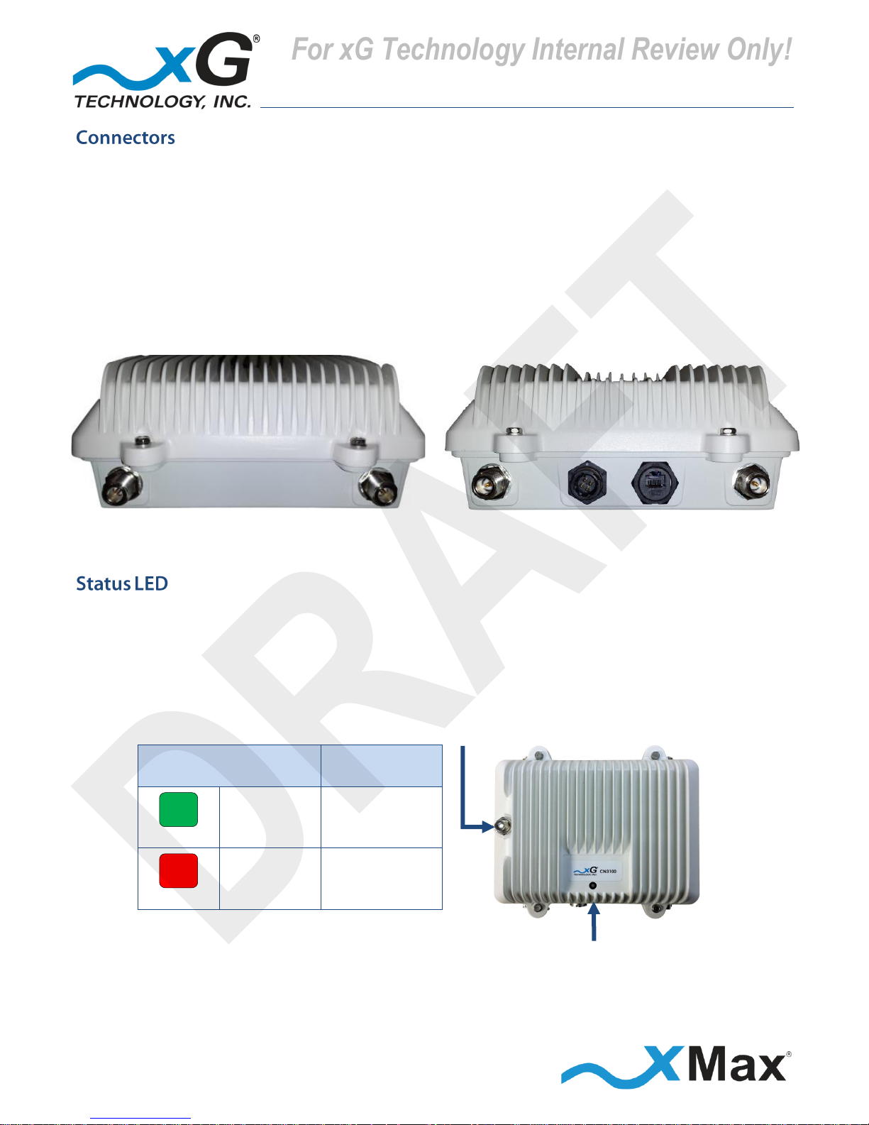
The CN3100 features seven connectors:
Four external xMax antenna connectors (N-type Jack, Female Socket)
A connector for an external WiFi antenna (TNC Jack, Female Socket)
A weatherproof Ethernet connector
A weatherproof Power connector
TOP CONNECTORS
BOTTOM CONNECTORS
Tx 3/Rx Tx 1/Rx
Rx 4
Power
Ethernet
Rx 2
The CN3100 Vehicle Modem Status LED indicates power, WiFi and network status and hardware fault
conditions.
Under normal operating conditions, the LED glows GREEN.
WiFi CONNECTOR
xMax Network
GREEN
SOLID
CONNECTED
RED
SOLID
NOT
CONNECTED
STATUS LED
For xG Technology Internal Review Only!
DRAFT
8
CN3100 Vehicle Modem - Installation Guide - G7609 - 3.0 - DRAFT
These notices apply to the CN3100 Vehicle Modem.
Be sure to read, understand and follow these instructions.
Heed all warnings.
Only use accessories and attachments specified by xG Technology.
Keep a copy of these instructions for future reference.
The CN3100 Vehicle Modem MUST only be installed by a professional installer. It is the responsibility
of the installer to adjust the transmit power level to ensure that the output power plus antenna gain
does not cause the device to exceed FCC Part 15 output power regulations.
Hazardous situation, which if not avoided,
could result in death or serious injury.
All antennas MUST either be located on the exterior of a vehicle or mounted on a pole.
Every antenna MUST be separated from users by more than 25 cm (0.82 ft) at all times.
Shielded and grounded Ethernet cable MUST be used to avoid damage to the CN3100 Modem
unit and ensure proper operation.
Lightning Protection MUST be used on all antenna connections and Ethernet tower runs.
NOTE
This equipment has been tested and found to comply with the limits for a Class B digital device,
pursuant to Part 15 of the FCC Rules. These limits are designed to provide reasonable protection
against harmful interference in a residential installation. This equipment generates, uses, and can
radiate radio frequency energy and, if not installed and used in accordance with the instructions, may
cause harmful interference to radio communications. However, there is no guarantee that
interference will not occur in a particular installation. If this equipment does cause harmful
interference to radio or television reception, which can be determined by turning the equipment off
and on, the user is encouraged to try to correct the interference by one or more of the following
measures:
Reorient or relocate the receiving antenna.
Increase the separation between the equipment and receiver.
Connect the equipment into an outlet on a circuit different from that to which the receiver is
connected.
Consult the dealer or an experienced radio technician for help.
For xG Technology Internal Review Only!
DRAFT
9
CN3100 Vehicle Modem - Installation Guide - G7609 - 3.0 - DRAFT
This equipment complies with FCC radiation exposure limits set forth for an uncontrolled environment.
This equipment should be installed and operated with minimum distance of 25 cm (0.82 ft) between
the radiator and your body. This transmitter MUST not be co-located or operating in conjunction with
any other antenna or transmitter.
Changes or modifications to this device not expressly approved
by xG Technology could void the user’s authority to operate
the equipment and void the product warranty.
For xG Technology Internal Review Only!
DRAFT
10
CN3100 Vehicle Modem - Installation Guide - G7609 - 3.0 - DRAFT
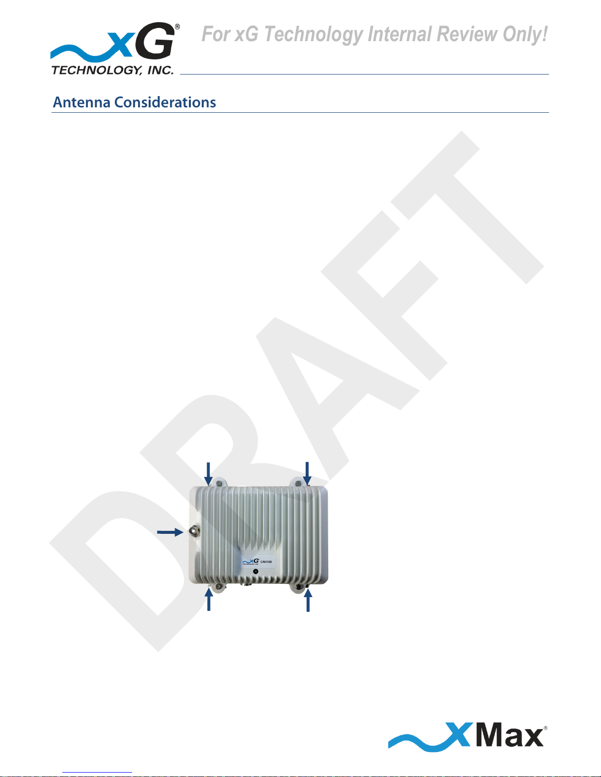
The CN3100 has four antenna connectors — two Tx/Rx and two Rx-only.
All connectors are always used.
The WiFi antenna can be positioned in any convenient location.
On a vehicle, magnetic-mount or through-hole mount antennas may be used.
FOR OPTIMUM PERFORMANCE
The CN3100 should be placed as close as possible to the antennas.
The antenna cable lengths should be as short as possible.
Use of Low-loss cables (LMR 195/240 or equivalent) is highly recommended.
When using four antennas
The cables from the two Tx/Rx connectors on the CN3100
should be connected to the two antennas on one diagonal.
The cables from the two Rx connectors on the CN3100
should be connected to the two antennas on the opposite diagonal.
When using two dual-polarity antennas, connect the cables as shown:
Vertical Polarity
Horizontal Polarity
Antenna 1
Antenna 2
WiFi
Antenna
Antenna 1
Antenna 2
Horizontal Polarity
Vertical Polarity
For additional information, please refer to the antenna configuration illustrations in the
Antenna Configurations section on page 11.
For xG Technology Internal Review Only!
DRAFT

11
CN3100 Vehicle Modem - Installation Guide - G7609 - 3.0 - DRAFT
The following illustrations show typical antenna configurations. The antennas must be separated by
at least 2 feet (0.6 meters) in horizontal and vertical orientation. This is the minimum separation
distance required for proper operation.
Four antennas are used with an Omni antenna installation. The antennas should be arranged in a
square configuration with two feet (2 ft.) separation on each side.
Two antennas are used with an xMax Vehicle Antenna installation. The antennas should be arranged
either in line or side-to-side, with two feet (2 ft.) separation between the antennas.
Side-to-Side
In-line
For xG Technology Internal Review Only!
DRAFT

12
CN3100 Vehicle Modem - Installation Guide - G7609 - 3.0 - DRAFT
For xG Technology Internal Review Only!
DRAFT

13
CN3100 Vehicle Modem - Installation Guide - G7609 - 3.0 - DRAFT
For xG Technology Internal Review Only!
DRAFT

14
CN3100 Vehicle Modem - Installation Guide - G7609 - 3.0 - DRAFT
This procedure should be completed before installing the CN3100 in a service location.
These steps set up the CN3100 Vehicle Modem for use. After completing these configuration steps,
the CN3100 Vehicle Modem will be fully functional and ready for installation and operation.
It will broadcast on the configured channel and enable any authorized Internet-ready device to
securely connect to the Internet through the xMax Network.
Devices may also be connected to the xMax network through a wired Ethernet connection to the
CN3100. For more information, refer to the topic Wired Internet Connectivity on page 20.
NOTE
This sequence assumes that the CN3100 device is in factory-default configuration
and has not been previously configured.
IMPORTANT: BEFORE YOU CONTINUE
Antennas or dummy loads MUST be connected to the two top Tx RF ports.
Both top Tx RF ports MUST be properly terminated
before power is applied to the unit.
Applying power without
proper RF port termination might damage the unit
and void the product warranty.
1. Use a laptop or desktop computer to configure the CN3100 Vehicle Modem.
Configure the computer network adapter to Internet Protocol Version 4 (TCP/IPv4) for a static IP
address and subnet mask.
BEFORE YOU CONTINUE
Be sure to take note of the current settings to restore them after configuration.
2. Use the IP Address as shown below:
Computer Network Adapter Settings
IP Address:
169.254.90.100
Subnet Mask:
255.255.255.0
3. Using an Ethernet cable, connect the computer to the Ethernet connector on the CN3100.
For xG Technology Internal Review Only!
DRAFT

15
CN3100 Vehicle Modem - Installation Guide - G7609 - 3.0 - DRAFT
4. Connect the flying leads on the supplied weatherproof power connector to a 12 to 19 VDC
power supply capable of providing 3 amp service.
5. Secure the power plug to the power connector on the CN3100 Vehicle Modem.
The Status LED glows RED within fifteen seconds after the power source is switched on.
NOTE
The CN3100 startup process takes two to three minutes.
Before continuing, wait until this process completes and the LED glows GREEN.
6. On the computer, open a Web browser.
In the browser address line, enter the IP address to open the CN3100 xVM Management window:
CN3100 Management
IP Address:
http://169.254.90.101
7. In the User name and Password fields enter:
User name:
admin
Password:
admin1
The password is case sensitive.
The CN3100 xVM Management window opens to the Home view.
For xG Technology Internal Review Only!
DRAFT

16
CN3100 Vehicle Modem - Installation Guide - G7609 - 3.0 - DRAFT
The menu bar is at the top of the window.
8. On the tool bar, click Settings to open to the Settings – WiFi view.
xG Technology strongly recommends that you change the SSID and WPA security key.
NOTE
Before saving changes, be sure to write down the new SSID, and then keep it in a safe place
for future reference:
SSID:
9. In the SSID field, enter a unique SSID for the device.
Select a security protocol:
10. Click the down arrow on the right side of the Security field to reveal the options menu.
11. Click the desired security protocol. The best, and most secure, level of security is WPA2.
Enter the desired security key/passphrase:
Be sure to write down the new Shared Key and then keep it in a safe place for future reference:
Shared Key
After confirming that the settings are written down for future reference, click Save.
For xG Technology Internal Review Only!
DRAFT

17
CN3100 Vehicle Modem - Installation Guide - G7609 - 3.0 - DRAFT
On the tool bar, click Accounts to open the User Accounts view.
The Change User Password section, displays the current Username.
xG Technology strongly recommends that you change the default Account Password.
IMPORTANT
Before clicking Apply, be sure to write down the new password, and then keep it in a safe place for
future reference.
The password length must be a minimum of 6 characters.
The password is case sensitive, and may contain any alphanumeric or special character.
Note the New Password:
12. Enter the selected password in the New Password field, and then again enter the password
in the Repeat Password field. Finally, click Apply.
The system displays the message:
Saving Settings! Please wait while the server saves your settings, and then followed by
Settings saved! Server has successfully saved your settings.
NOTE
This completes the minimum setup. For additional information on the many features of the
CN3100 xVM Management tool, please refer to the topic CN3100 Vehicle Modem Management Tool
starting on page 21.
13. To complete the setup, log out of the CN3100 xVM Management. On the right side of tool bar
click Logged In to reveal the options menu, and then click Log Out.
14. Be sure to restore the computer network adapter to its previous settings.
For xG Technology Internal Review Only!
DRAFT

18
CN3100 Vehicle Modem - Installation Guide - G7609 - 3.0 - DRAFT
NOTE
xG Technology recommends that the CN3100 Vehicle Modem be configured on a bench before
installing the device in the field. See Configuring the CN3100 Vehicle Modem on page 14.
This checklist may be of assistance in assembling the parts needed to complete the installation.
CN3100 Vehicle Modem Parts Checklist
SUPPLIED BY xG Technology
OBTAIN FROM YOUR PART SUPPLIER
1
CN3100 with Wall Mount Bracket
1
Ethernet Cable
(for configuration)
1
Weatherproof Ethernet Kit
1
In-line Fuse Holder
(Littelfuse FHA010 or equivalent)
1
Weatherproof Power Connector
with 3 ft. cable
1
Fuse (10 Amp ATO®)
2
Magnetic Mount xMax Antennas
1
Magnetic Mount WiFi Antenna
Alternative CN3100 mounting
solution (as ordered)
For xG Technology Internal Review Only!
DRAFT

19
CN3100 Vehicle Modem - Installation Guide - G7609 - 3.0 - DRAFT
These steps outline the basic tasks required to complete a successful installation.
Your specific steps will depend upon the requirements of your system design.
1. Select an appropriate location to mount the CN3100 Vehicle Modem and secure it in place with
an appropriate mounting bracket.
2. Position the Magnetic Mount xMax Antennas on the roof of the vehicle as shown in the topic
Antenna Configurations on page 11. For optimum performance, the antennas should be arranged
with a separation of two feet (2 ft.) between the antennas.
3. Position the Magnetic Mount WiFi Antenna on the roof of the vehicle in any convenient location.
4. Route the cables to the CN3100 unit location, and then connect the cables from the antennas to
the CN3100 unit.
IMPORTANT
Ensure that the correct antenna cable is attached to correct CN3100 connector, as shown in the
diagrams in the topic Antenna Configurations starting on page 11.
5. Connect the flying leads of the supplied weatherproof power plug cable to a in-line fuse holder
fitted with a 10 Amp fuse.
6. Connect the fuse holder cable to a 12 to 19 VDC power source capable of providing 3 amp service.
7. Secure the power plug to the power connector on the CN3100 Vehicle Modem.
Within 15 seconds after the power source is applied, the Status LED glows RED.
If the CN3100 is within range of an xMax Network, it connects within 2 minutes and the LED glows
GREEN.
The CN3100 Vehicle Modem is now fully functional and provides IEEE 802.11 wireless connections to
wireless devices.
NOTES
If the Status LED remains RED after two minutes have elapsed,
ensure that the CN3100 is within range of an operating xMax Network.
If the CN3100 is within range of an operating xMax Network, but not connecting,
follow these steps to restart the CN3100:
Power off the CN3100.
Wait 60 seconds.
Power on the CN3100.
For xG Technology Internal Review Only!
DRAFT

20
CN3100 Vehicle Modem - Installation Guide - G7609 - 3.0 - DRAFT
When within range of an operating CN3100 Vehicle Modem, any authorized Internet-ready device is
enabled to securely connect to the Internet through the xMax Network.
These steps connect WiFi devices to the xMax Network.
1. Configure a WiFi-enabled device for Internet Protocol Version 4 (TCP/IPv4) and DHCP operation.
2. Enter the SSID and password that was saved in the steps performed in the section
Configuring the CN3100 Vehicle Modem on page 14.
Once connected, the device can be used for any common Internet function.
A properly configured device, such as a PC or laptop computer, can be connected directly to
the CN3100 Vehicle Modem for Internet access.
1. Configure the device network interface for DHCP operation.
2. Using the provided Ethernet cable, connect the device to the operating
CN3100 Vehicle Modem.
For xG Technology Internal Review Only!
DRAFT

21
CN3100 Vehicle Modem - Installation Guide - G7609 - 3.0 - DRAFT
Much like a common wireless router, the CN3100 Vehicle Modem requires only minimal
configuration for general use. Additional configuration features, however, are available using the
CN3100 Vehicle Modem Management tool.
The CN3100 Vehicle Modem tool provides a means to perform the complex configuration tasks
in a visually appealing, Web-based interface. In addition, the tool provides powerful facilities
for network monitoring and analysis.
Before You Begin
Ensure that the computer network adapter is configured is as described in the topic
Configuring the CN3100 Vehicle Modem on page 14.
1. On the computer, open a Web browser, type the CN3100 Vehicle Modem IP address in the
address line, and then press Enter:
CN3100 Vehicle Modem Management
IP Address:
http://169.254.90.101
2. The User Authentication window displays.
Enter the User Name and Password, as saved in the topic Configuring the CN3100 Vehicle
Modem on page 14, and then click Log In.
For xG Technology Internal Review Only!
DRAFT

22
CN3100 Vehicle Modem - Installation Guide - G7609 - 3.0 - DRAFT
The CN3100 Vehicle Modem window opens to the Home view, as shown.
Figure 1: CN3100 Vehicle Modem – Home View
There are six CN3100 Vehicle Modem Management tabs at the top of the window.
Each of these tabs presents additional CN3100 Vehicle Modem Management functions.
Topics in this section describe the functions of each CN3100 Vehicle Modem Management tab.
For xG Technology Internal Review Only!
DRAFT

23
CN3100 Vehicle Modem - Installation Guide - G7609 - 3.0 - DRAFT
This diagram shows the major functions in each of the CN3100 Vehicle Modem Management
views. Topics in this guide describe the features and usage information for each CN3100 Vehicle
Modem Management function. Click one of the six CN3100 Vehicle Modem Management tabs, at
the top of the window, to display that view.
VIEW
CONTENT AND FUNCTIONS OVERVIEW
Toolbar
Options
Click the arrow to the right of the of Logged In status to reveal the options
Click Edit Account to display the User Accounts view.
Click to select the CN3100 Management Dark Theme or Light Theme.
Click to Log Out of CN3100 Vehicle Modem Management.
Home
The Home view displays a real-time overview of CN3100 system information:
System Information
Device
Hostname, IP Address, Time, Uptime, CPU
Memory
Total Available, Free, Used, Buffers, Cached
Traffic Statistics
Interface, Alias, Bytes (In/Out), Packets (In/Out), MTU
Active Clients
IP Address, MAC Address, Type
Information
Device Information
Home
Version, Wireless, Network, Control System Components
xMax
WAN Information:
Configuration Type, Total Traffic, RF Settings, Wireless
WiFi
Status, Packets, Clients
System
Device, Memory, Traffic Statistics, Active Clients
Tools
Network Tools: Ping, Trace Route, NS Lookup
Restart: CN3100 Vehicle Modem
Settings
WiFi
WiFi Radio Enable, Broadcast SSID Enable, SSID,
Broadcast Channel, Security
xMax Radio
RF Channel, Network ID, Transmit Power,
Enable/Disable Other Parameters
Other
Date/Time: Set or Sync
RADIUS Secret, System Reboot Enable
Logs
View
messages, debug, syslog, Dmesg, WdReboot
Accounts
User Accounts
Change User Password
Upgrade
Sofware Upgrade
Display Current Software and xMax Components, Upload File,
Swap to Backup
Figure 2: CN3100 Vehicle Modem Management – Content and Functions Overview
For xG Technology Internal Review Only!
DRAFT

24
CN3100 Vehicle Modem - Installation Guide - G7609 - 3.0 - DRAFT
The Home view is the initial page
presented.
This page displays real-time System
Information from the xMCC database
for:
Devices
Memory
Traffic Statistics
Active Clients
The Information – Home view
displays Device Information:
Version
Wireless
Network
Control System Components
For xG Technology Internal Review Only!
DRAFT

25
CN3100 Vehicle Modem - Installation Guide - G7609 - 3.0 - DRAFT
The Information – xMax view
displays WAN Information:
Configuration Type
Total Traffic
RF Settings
Wireless
The Information – WiFi view displays
WAN Information:
Wireless Status
Wireless Packets
Wireless Clients
For xG Technology Internal Review Only!
DRAFT

26
CN3100 Vehicle Modem - Installation Guide - G7609 - 3.0 - DRAFT
The Information – Sys-Info view
displays System Information:
Device
Memory
Traffic Statistics
Active Clients
The Information – Tools view
displays System Tools:
Network Tools
Click the down arrow to
the right of Ping to reveal
the other tools:
Option: Restart Device
For xG Technology Internal Review Only!
DRAFT

27
CN3100 Vehicle Modem - Installation Guide - G7609 - 3.0 - DRAFT
The Settings – WiFi view displays
WiFi Settings:
WiFi Radio Enable
Broadcast SSID Enable
SSID
Broadcast Channel
Security
The Settings – xMax view displays
Radio Settings:
RF Channel
Network ID
Use Fixed Channel and ID
Transmit Power
Enable:
Hardcoded CDT Mode
Rate Selection
Timing Advance
One CN3100 Vehicle Modem
Mode Only
For xG Technology Internal Review Only!
DRAFT

28
CN3100 Vehicle Modem - Installation Guide - G7609 - 3.0 - DRAFT
The Settings – Other view enables
configuration of additional settings:
RADIUS Secret
Enable System Reboot
Date/Time Settings:
Manually set date, time,
and time zone, or
Time/Date Sync Options:
Automatically syncs the date and time with a preset Internet time IP address.
Acquires the date and time from the current local machine and sets it to that device.
Syncs the date and time with a specific NTP server.
The Logs view enables viewing of
CN3100 Vehicle Modem logs. Scroll
down to view any available log.
messages
Software Events
debug
Debug Events
syslog
All Events
Dmesg
Hardware Events
wdReboot
Reboot Events
Useful icons are available in the
upper right corner of each log frame:
Click to enable filtering of
searched information.
Click to download the Log file
in .TXT format.
For xG Technology Internal Review Only!
DRAFT

29
CN3100 Vehicle Modem - Installation Guide - G7609 - 3.0 - DRAFT
The Accounts view enables the
currently logged-in user to update
the account password.
The Upgrade view displays the
software versions for the CN3100
Vehicle Modem components:
Software Components
xMax Components
This view also enables upgrading and
rollback of the firmware and software
on the CN3100 Vehicle Modem.
For xG Technology Internal Review Only!
DRAFT

30
CN3100 Vehicle Modem - Installation Guide - G7609 - 3.0 - DRAFT
SYSTEM OVERVIEW
Frequency Band:
902-928 MHz
Channel Bandwidth:
1.44 MHz
Modulation:
Adaptive BPSK / QPSK / QAM16 / QAM64
Spectral Efficiency:
Up to 4.25 Bits/Hz
PHY Protocol:
Proprietary OFDM, 2x4 MIMO
Max Simultaneous
Users per Channel:
200 Users
Mobility:
Up to 100 MPH
Handoff:
Sessions maintained in CN3100 to CN3100 handoffs
Data rate:
Per channel: up to 6 Mbps; Aggregate (16 channels): up to 96 Mbps
RADIO PERFORMANCE
Tx Power Output
RANGE: Up to 24 dBm in 1 dB steps (BPSK, QPSK, QAM 16/64)
Receiver Sensitivity:
-100 dBm BPSK/-90 dBm QAM64
ANTENNA CONNECTORS
Four N-type female (xMax), one TNC-type female (GPS)
POWER
PoE++ (Power over Ethernet Plus) Power Supply with Power Cord
Input: 100-240 VAC, 50-60 Hz; Output: 56 V 0.9 A up to 50 W 100 M
PHYSICAL DESCRIPTION
Size:
8.5” x 7.5” x 3.5” (21.59 cm x 19.05 cm x 8.89 cm) excluding antenna
Weight:
5 lbs. (2.27 kg), excluding antenna
Interface:
100BASE-T Ethernet
ENVIRONMENTAL
Operating Temp:
-40° to 122° F (-40° to 50° C)
Water/Dust:
IP67
Humidity:
0-100% condensing
REGULATORY
EMC:
FCC CFR 47 Part 15 Class B
Vibration and Shock:
MIL-STD 810F Method 514.5 Vibration (constant acceleration),
MIL-STD 810F Method 516.5 Shock
MANAGEMENT
NMS:
xMonitor® Proprietary Event/Fault Manager
SNMP Management
For xG Technology Internal Review Only!
DRAFT

31
CN3100 Vehicle Modem - Installation Guide - G7609 - 3.0 - DRAFT
CN3100 Vehicle Modem
xG Technology, Inc. (“xG”)
240 South Pineapple Avenue, Suite 701
Sarasota, FL 34236
Unless a different period is specified for a particular hardware Product, or in a sales agreement
between xG and customer, or in the published specification sheet for the hardware Product, xG's
hardware Products are generally warranted against defects in workmanship and materials for a
period of twelve (12) months from the date of original purchase, provided the Product remains
unmodified and is operated under normal and proper conditions. Unless otherwise so provided the
warranty period for computer programs in machine-readable form included in a hardware Product,
which are essential for the functionality will be coincident with the warranty period of the
hardware Product. Software patches, bug fixes or workarounds do not extend the original warranty
period. For Software sold by xG and run outside the hardware Product (e.g. xMCC), the warranty
term is 90 days from date of original purchase. All accessories (e.g. antennas, cables, power supply,
POE) carry a warranty term of 90 days from date of original purchase.
The Limited Warranty extends only to the original purchaser of the Product from xG, or its
authorized Resellers, and is not assignable or transferable to any subsequent purchaser or enduser.
xG’s warranty applies only to a Product that is manufactured by or for xG Technology and is
identified within xG’s price book at time of purchase. Any products not covered by xG’s warranty,
but supplied under the customer's Purchase Order with xG as part of the delivered equipment, are
covered under that manufacturer's standard warranty and any warranty claims should be handled
directly with that manufacturer.
xG’s warranty shall not apply: (i) to any Product subjected to accident, misuse, neglect, alteration,
acts of God, improper handling, improper transport, improper storage, improper use or application,
improper installation, improper testing or unauthorized repair; (ii) use of parts or accessories not
approved or supplied by xG, or failure to perform operator handling and scheduled maintenance
instructions supplied by xG or (iii) to cosmetic problems or defects that result from normal wear
and tear under ordinary use, and do not affect the performance or use of the Product.
If the Product develops a covered defect within the warranty period, xG will, at its option, either
repair or replace the Product found by xG to be defective or not in conformity with material
specifications, provided that the Product is returned during the warranty period.
For xG Technology Internal Review Only!
DRAFT

32
CN3100 Vehicle Modem - Installation Guide - G7609 - 3.0 - DRAFT
Customer is responsible for shipment to xG (or authorized service provider) and assumes all costs
and risks associated with this transportation; return shipment to the Customer will be at xG’s
expense. Customer shall be responsible for return shipment charges for Product returned where xG
determines there is no defect ("No Defect Found"), or for Product returned that xG determines is
not eligible for warranty repair. No charge will be made to customer for replacement parts for
warranty repairs.
Product that has been repaired or replaced may consist of refurbished equipment that contains
used components, some of which have been reprocessed. The used components comply with xG
Product performance and reliability specifications. The repair services provided are warranted
against defects in workmanship and materials on the repaired component of the product for a
period of 30 days from the shipment date of the repaired product, or until the end of the original
warranty period, whichever is longer.
xG is not responsible for any damage to or loss of any software programs, data or removable data
storage media, or the restoration or reinstallation of any software programs or data other than the
software, if any, installed by xG during manufacture of the Product or shipped with Product. xG’s
sole obligation for software that when properly installed and used does not substantially conform
to the published specifications in effect when the software is first shipped by xG, is to use
commercially reasonable efforts to correct any reproducible material non conformity (as
determined by xG at its sole discretion) by providing Customer with: (a) telephone or e-mail access
to report non conformance so that xG can verify reproducibility; (b) a software patch or bug-fix, if
available, or a workaround to bypass the issue, if available; and (c) where applicable, replacement
of damaged or defective external media, such as a CD-ROM disk, on which the software was
originally delivered. xG does not warrant that the use of the software will be uninterrupted, errorfree, free of security vulnerabilities, or that the software will meet Customer’s particular
requirements. Customer’s sole and exclusive remedy for breach of this warranty is, at Seller's
option, to receive (i) suitably modified software, or part thereof, or (ii) comparable replacement
software or part thereof.
Because it is impossible for xG to know the purposes for which the purchaser acquired this Product
or the uses to which this Product will be put, the purchaser assumes full responsibility for the
selection of the Product for its installation and use. While every reasonable effort has been made
to insure that the purchaser will receive a Product that can be used and enjoyed, xG does not
warrant that the functions of the Product will meet the purchaser’s requirements or that the
operation of the Product will be uninterrupted or error-free. xG is not responsible for problems
caused by the interaction of the Product with any other software or hardware.
For xG Technology Internal Review Only!
DRAFT

33
CN3100 Vehicle Modem - Installation Guide - G7609 - 3.0 - DRAFT
To obtain warranty service or technical support, please contact the party from whom you
purchased the product. If you purchased the product directly from xG, contact your xG Sales
Representative or call 754-206-4800. To take advantage of this Limited Warranty Purchasers are
required to supply an original point of purchase receipt. Returned Product must be accompanied by
the purchaser’s sales receipt or comparable substitute proof of sale showing the date of purchase,
the serial number of Product, and the sellers’ name and address (if purchased through a authorized
xG reseller).
This Limited Warranty Policy shall be the sole and exclusive remedy of the purchaser with respect
to xG’s Products. xG's sole liability on any claim arising out of the sale of the Product or xG's
replacement of defective product, whether in contract, warranty, tort, or otherwise shall be limited
to the purchase price of the goods that prove defective or nonconforming. In no event shall xG be
liable for, and purchaser shall hold xG harmless from, any damages, direct, indirect, or
consequential, whether resulting from xG's negligence or otherwise, arising out of, in connection
with, or resulting from the goods sold to the Purchaser (including, without limitation, damages, for
loss of business profits, business interruption, loss of information, or any other pecuniary loss), and
any and all claims, actions, suits, and proceedings which may be instituted in respect to the
foregoing, including those made by subsequent owners and users of the goods. In no event shall xG
be liable for damages from alleged negligence, breach of warranty, strict liability, incidental or
consequential damages, or any other theory, other than the Limited Warranty set forth herein.
xG neither assumes nor authorizes any of its dealers, representatives, or any other person or entity
to assume for it any other obligation or liability beyond that which is expressly provided for in this
Limited Warranty.
xG MAKES NO WARRANTY OTHER THAN THE LIMITED WARRANTY REFERRED TO HEREIN. THIS
LIMITED WARRANTY IS EXPRESSLY IN LIEU OF ANY AND ALL OTHER EXPRESS OR IMPLIED
WARRANTIES, INCLUDING ANY IMPLIED WARRANTY OF MERCHANTABILITY OR FITNESS FOR A
PARTICULAR PURPOSE, AND IT CONSTITUTES THE ONLY WARRANTY MADE WITH RESPECT TO THE
GOODS COVERED BY THESE TERMS AND CONDITIONS. xG SHALL UNDER NO CIRCUMSTANCES BE
LIABLE FOR ANY INCIDENTAL OR CONSEQUENTIAL DAMAGES.
For xG Technology Internal Review Only!
DRAFT

G7609 - Release 3.0 - DRAFT
Vehicle Modem
© Copyright xG Technology, Inc. 2015. All Rights Reserved.
xG Technology, Inc.
240 South Pineapple Avenue, Suite 701
Sarasota, FL 34236
(941) 953-9035
www.xGTechnology.com
For xG Technology Internal Review Only!
 Loading...