

xG Technology CN1100 Installation Manual
G7601 - Release 3.8

2
CN1100 Access Point - Installation Guide - G7601 - 3.8
Product features and specifications are subject to change without prior notice.
xG® and xMax® are registered trademarks of xG Technology, Inc.
All other trademarks used herein are property of their respective owners.
For the latest product documentation and software
updates, please refer to our Web site at
www.xGTechnology.com/support
xG Technology, Inc.
240 South Pineapple Avenue, Suite 701
Sarasota, FL 34236
(941) 953-9035
www.xGTechnology.com

3
CN1100 Access Point - Installation Guide - G7601 - 3.8
Table of Contents
Introduction ............................................................................................................... 7
About this Product .................................................................................................................... 7
About this Book ........................................................................................................................ 7
Before You Begin ...................................................................................................................... 7
Hardware Overview .................................................................................................... 8
Powering the CN1100 ............................................................................................................... 8
Connectors ................................................................................................................................ 9
Status LED ................................................................................................................................. 9
Important Safety and Installation Requirements ...................................................... 10
FCC Part 15 Requirement ....................................................................................................... 10
Hazard ..................................................................................................................................... 10
FCC Compliance ...................................................................................................................... 10
RF Exposure ............................................................................................................................ 11
Antenna Considerations ........................................................................................... 12
Antenna Configurations ............................................................................................ 13
Sector Antenna Configuration ................................................................................................ 13
Omni Antenna Configuration ................................................................................................. 14
Panel Antenna Configuration ................................................................................................. 15
Configuring the CN1100 Access Point ........................................................................ 16
Installation Preparation ............................................................................................ 22
Assemble Your Parts and Tools .............................................................................................. 22
Equipment Provided in the Standard CN1100 Access Point Kit ............................................. 24
Antenna Mounting Solutions ................................................................................................. 25
Installation Procedure Overview ............................................................................................ 26
Antenna Cabling Identification ............................................................................................... 27
Antenna Orientation Overview .............................................................................................. 28
Antenna Alignment ......................................................................................................................... 28
Antenna Azimuth ............................................................................................................................. 28
Antenna Tilt ..................................................................................................................................... 28
Estimating Installation Times ................................................................................................. 29
Completion and Quality Control Check List ........................................................................... 30
Installation Details .................................................................................................... 31
Panel Antenna Assembly ........................................................................................................ 31
Mounting Bracket ............................................................................................................................ 31
U-Bolts ............................................................................................................................................. 32

4
CN1100 Access Point - Installation Guide - G7601 - 3.8
GPS Antenna .................................................................................................................................... 32
Antenna Installation and Adjustment Overview .................................................................... 33
Antenna Azimuth Adjustment ......................................................................................................... 33
Mechanical Tilt Adjustment ............................................................................................................ 33
Tower Installation Example ............................................................................................................. 33
Installation Procedure ............................................................................................................ 34
CN1100 Management Tool ....................................................................................... 37
Overview ................................................................................................................................. 37
CN1100 Management – Content and Functions ............................................................................ 38
CN1100 Management Details ................................................................................................ 39
Home View ...................................................................................................................................... 39
Information View – Home ............................................................................................................... 39
Information View – xMax ................................................................................................................ 40
Information View – GPS .................................................................................................................. 40
Information View – SNMP ............................................................................................................... 40
Information View – System Information ......................................................................................... 41
Information View – Tools ................................................................................................................ 41
Settings View – LAN ......................................................................................................................... 42
Settings View – xMax ...................................................................................................................... 42
Settings View – SNMP .................................................................................................................... 43
Settings View – xDrive ..................................................................................................................... 43
Settings View – Other ...................................................................................................................... 43
Logs View ......................................................................................................................................... 44
Accounts View ................................................................................................................................. 44
Upgrade View .................................................................................................................................. 45
Setting Up xMax with SON (Self Organizing Network) ............................................... 46
SON Rules Table ...................................................................................................................... 46
One Channel Selected - Locked Channel ......................................................................................... 46
Preferred, Enabled and Disabled Channels ..................................................................................... 46
xMax Network Management ................................................................................................. 47
Auto Channel Selection upon Boot ................................................................................................. 47
Periodic Re-scan for a Better Channel ............................................................................................ 47
xMods / xVMs Always Scan ............................................................................................................. 47
Configuring xMax with SON ................................................................................................... 48
Channel Selection Tips ............................................................................................................ 49
Sample Network Architecture ................................................................................................ 50
Available Optional xMax Services .......................................................................................... 51

5
CN1100 Access Point - Installation Guide - G7601 - 3.8
Technical Specifications ............................................................................................ 52
Warranty .................................................................................................................. 53
Limited Warranty .................................................................................................................... 53
SCOPE OF THE WARRANTY .............................................................................................................. 53
ADDITIONAL PROVISIONS OF THE WARRANTY ............................................................................... 54
OBTAINING SERVICE AND SUPPORT UNDER WARRANTY ............................................................... 55
EXCLUSIVITY OF THE WARRANTY .................................................................................................... 55
List of Figures
Figure 1 — Sector Antenna Configuration ................................................................................................ 13
Figure 2 — Omni Antenna Configuration ................................................................................................. 14
Figure 3 —Panel Antenna Configuration .................................................................................................. 15
Figure 4 — CN1100 Access Point Parts Checklist ..................................................................................... 22
Figure 5 — Installation Tool Kit Checklist ................................................................................................. 23
Figure 6 —CN1100 Management – Content and Functions Overview .................................................... 38

6
CN1100 Access Point - Installation Guide - G7601 - 3.8
THIS PAGE INTENTIONALY LEFT BLANK
7
CN1100 Access Point - Installation Guide - G7601 - 3.8
The xMax® CN1100 is an all-IP, high-capacity, high-performance wireless access point that delivers
unmatched range, coverage and reliability in even the most challenging conditions. The CN1100 is a
waterproof, ruggedized device, and built to operate in wide temperature ranges. The CN1100 Access
Point is designed for installation in fixed and rapid deployment platforms.
This manual provides basic instructions for installation and configuration of the CN1100 Access Point.
IMPORTANT
The CN1100 Access Point MUST only be installed by a professional installer. For additional
information, please refer to the statement FCC Part 15 Requirement on page 12.
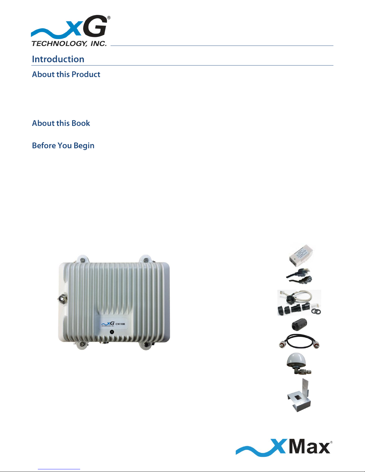
The CN1100 Access Point is shipped with the parts needed for installation and operation. These
items are shown below. Be sure each item is included in your product package. If any item is
missing, please contact the place of purchase.
Depending upon the requirements of your installation, you will also need to purchase
additional components such as antennas, cables, and surge protectors. A checklist of the
typically required parts is shown in the topic Assemble Your Parts and Tools on page 22.
PoE++ 56 VDC
Power Supply
AC Power Cord
Weatherproof
Ethernet Kit
Ferrite Beads
Antenna Cables
CN1100 Access Point
GPS Antenna
with right-angle
connector
Mounting Hardware
8
CN1100 Access Point - Installation Guide - G7601 - 3.8
The CN1100 Access Point is a compact form-factor base station used for communicating wirelessly
with CN5100 Mobile Hotspots and other xMax bridge devices. The xMax CN1100 is an all-IP, highcapacity, high-performance wireless access point that delivers wide-area coverage and reliability,
even when there is significant interference. The CN1100 is totally protected against dust and
moisture.
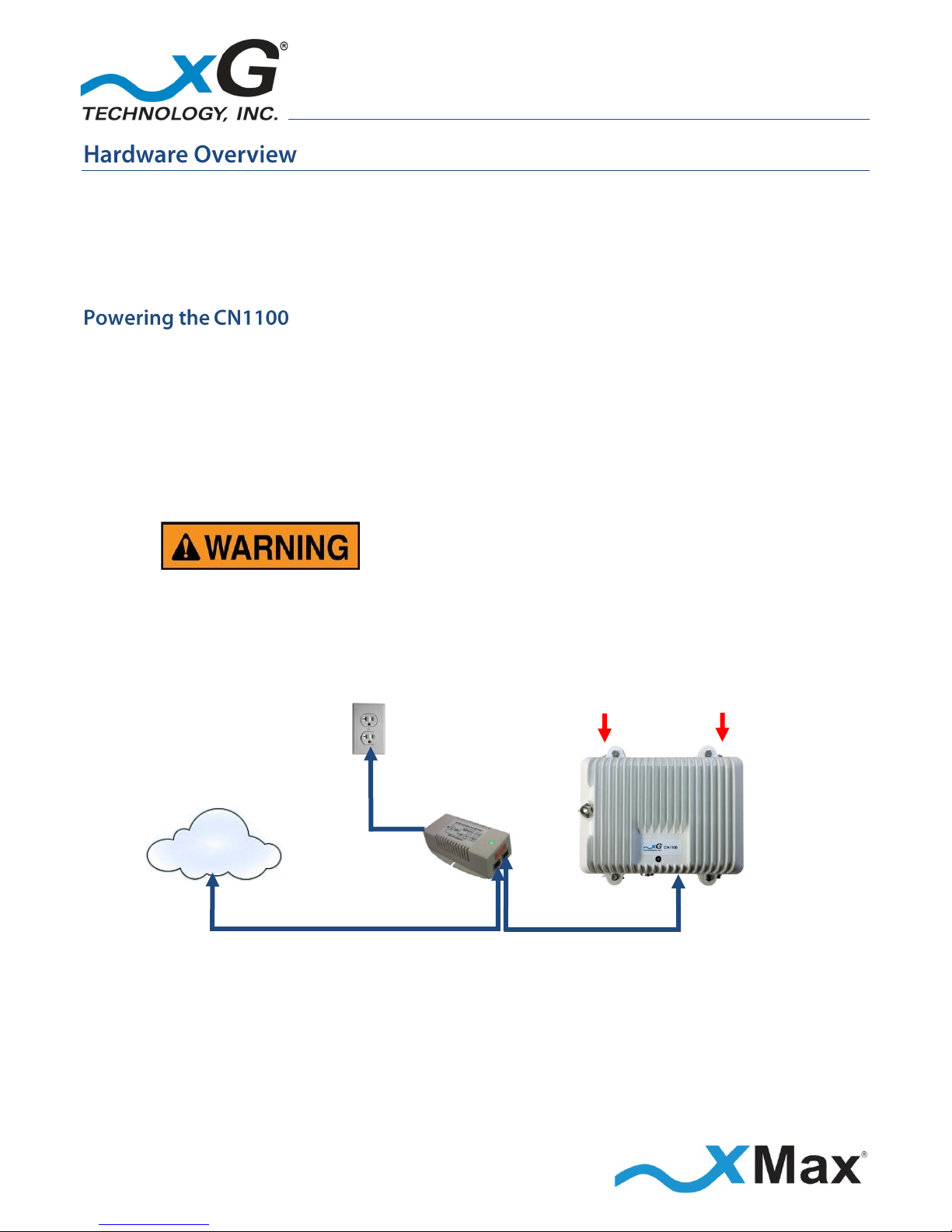
The CN1100 is a Power-over-Ethernet (PoE++) device. The PoE++ standard enables transmission
of both data and the power to operate a device over a single Cat5 cable connection.
The CN1100 REQUIRES a PoE++ adaptor, as supplied.
The device will NOT operate with a low-power PoE switch or adaptor.
Both Tx RF ports MUST be properly terminated
before power is applied to the unit.
Applying power without proper RF port
termination might damage the unit
and void the product warranty.
Public
or
Private
Internet
110-240
VAC,
50-60 Hz
PoE++
Power Supply
CN1100
DATA OVER
ETHERNET
POWER
plus DATA
TERMINATE
BEFORE
POWER UP
9
CN1100 Access Point - Installation Guide - G7601 - 3.8
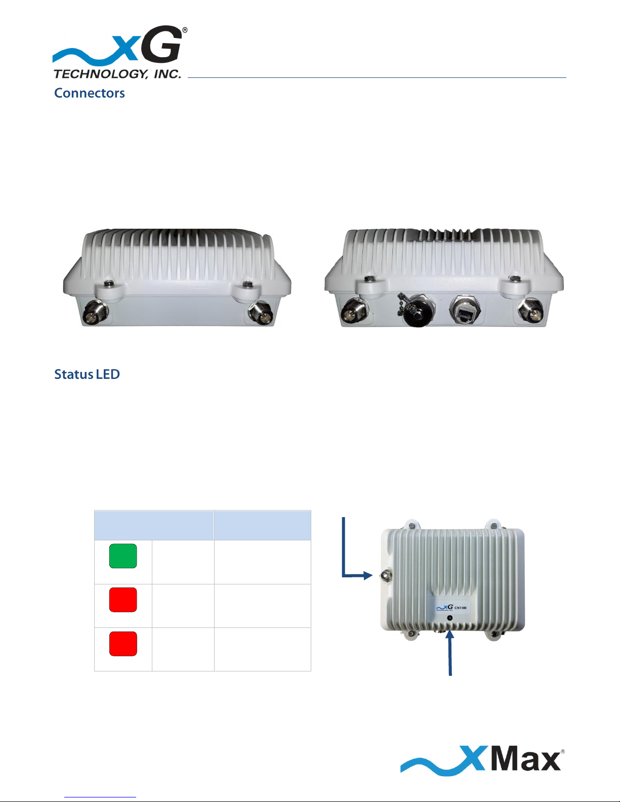
The CN1100 features seven connectors:
Four external xMax antenna connectors (N-type Jack, Female Socket)
A connector for an external GPS antenna (TNC Jack, Female Socket)
A weatherproof Ethernet connector
An unused connector
TOP CONNECTORS
BOTTOM CONNECTORS
Tx3/Rx3 Tx1/Rx1
Rx4
Unused Port
Ethernet
Rx2
The CN1100 Access Point Status LED glows to indicate power, network status and hardware fault
conditions:
GREEN indicates Normal Operation
Backhaul is present, GPS is present, and the device is transmitting beacons.
Solid RED indicates that the device is booting up, or no backhaul is detected.
Flashing RED indicates that no GPS signal is present.
GPS CONNECTOR
LED Status
xMax Network
GREEN
SOLID
NORMAL
RED
SOLID
BOOTING OR
NO BACKHAUL
RED
FLASHING
NO GPS SIGNAL
STATUS LED
10
CN1100 Access Point - Installation Guide - G7601 - 3.8
These notices apply to the CN1100 Access Point.
Be sure to read, understand and follow these instructions.
Heed all warnings.
Only use accessories and attachments specified by xG Technology.
Keep a copy of these instructions for future reference.
The CN1100 Access Point MUST only be installed by a professional installer. It is the responsibility of
the installer to adjust the transmit power level to ensure that the output power plus antenna gain
does not cause the device to exceed FCC Part 15 output power regulations.
Hazardous situation, which if not avoided,
could result in death or serious injury.
All antennas MUST either be located on the exterior of a vehicle or mounted on a pole.
Every antenna MUST be separated from users by more than 25 cm (0.82 ft) at all times.
Shielded and grounded Ethernet cable MUST be used to avoid damage to the CN1100 Access
Point and ensure proper operation.
Lightning Protection MUST be used on all antenna connections and Ethernet tower runs.
NOTE
This equipment has been tested and found to comply with the limits for a Class B digital device,
pursuant to Part 15 of the FCC Rules. These limits are designed to provide reasonable protection
against harmful interference in a residential installation. This equipment generates, uses, and can
radiate radio frequency energy and, if not installed and used in accordance with the instructions, may
cause harmful interference to radio communications. However, there is no guarantee that
interference will not occur in a particular installation. If this equipment does cause harmful
interference to radio or television reception, which can be determined by turning the equipment off
and on, the user is encouraged to try to correct the interference by one or more of the following
measures:
Reorient or relocate the receiving antenna.
Increase the separation between the equipment and receiver.
Connect the equipment into an outlet on a circuit different from that to which the receiver is
connected.
Consult the dealer or an experienced radio technician for help.

11
CN1100 Access Point - Installation Guide - G7601 - 3.8
This equipment complies with FCC radiation exposure limits set forth for an uncontrolled
environment.
This equipment should be installed and operated with minimum distance of 25 cm (0.82 ft)
between the radiator and your body. This transmitter MUST not be co-located or operating
in conjunction with any other antenna or transmitter.
Changes or modifications to this device not expressly approved
by xG Technology could void the user’s authority to operate
the equipment and void the product warranty.
12
CN1100 Access Point - Installation Guide - G7601 - 3.8
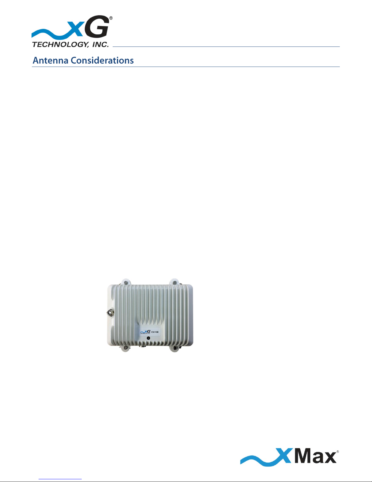
The CN1100 is a 2x4 MIMO device with four antenna connectors — two Tx/Rx and two Rx-only.
All connectors are always used.
Omni, Panel, and Sector antenna configurations are supported.
For optimum performance, the CN1100 should be placed as close as possible to the antennas.
The antenna cable lengths should be as short as possible.
When the antennas are not co-located with the CN1100, grounded bulkhead lightning arresters
should be installed on each cable. xG Technology recommends using L-com AL-NMNFB-9, or
equivalent, lightning arresters.
The GPS antenna is mounted directly to the CN1100 with the provided right-angle connector;
if desired, it may be mounted in any other convenient location and connected using a suitable
cable.
FOR OPTIMUM PERFORMANCE
Low-loss cables (LMR® 195/240 or equivalent) are highly recommended.
The cables from the two Tx/Rx connectors on the CN1100 should be connected
to the two antennas on one diagonal.
The cables from the two Rx connectors on the CN1100 should be connected
to the two antennas on the opposite diagonal.
Tx 1/Rx 1
VERTICAL
Tx 3/Rx 3
HORIZONAL
Rx 4
HORIZONAL
Rx 2
VERTICAL
For additional information, please refer to the antenna configuration illustrations in the topic
Antenna Configurations starting on page 13.
13
CN1100 Access Point - Installation Guide - G7601 - 3.8
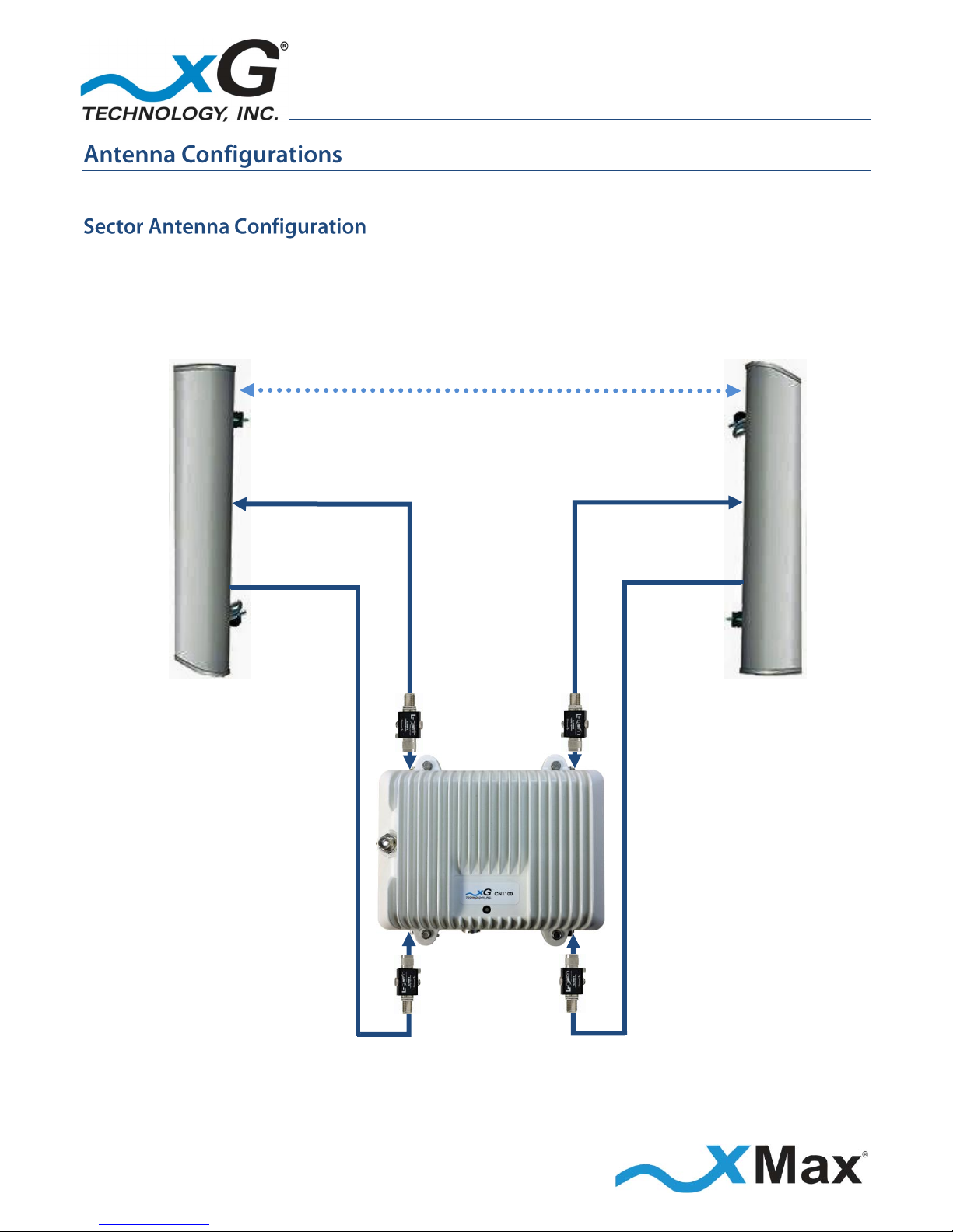
The following illustrations show typical antenna configurations.
When 2x2 MIMO sector antennas are used, they must be separated by at least 2 feet (0.6 meters) in
horizontal or vertical orientation. This is the minimum separation distance required for proper
operation.
The only sector antenna approved for use with the CN1100 is the Ubiquiti AM-9M13-120.
2 feet (0.6 m)
Tx1/Rx1
Tx1/Rx3
VERTICAL
HORIZONAL
HORIZONAL
VERTICAL
Rx4
Rx2
Figure 1 — Sector Antenna Configuration
14
CN1100 Access Point - Installation Guide - G7601 - 3.8
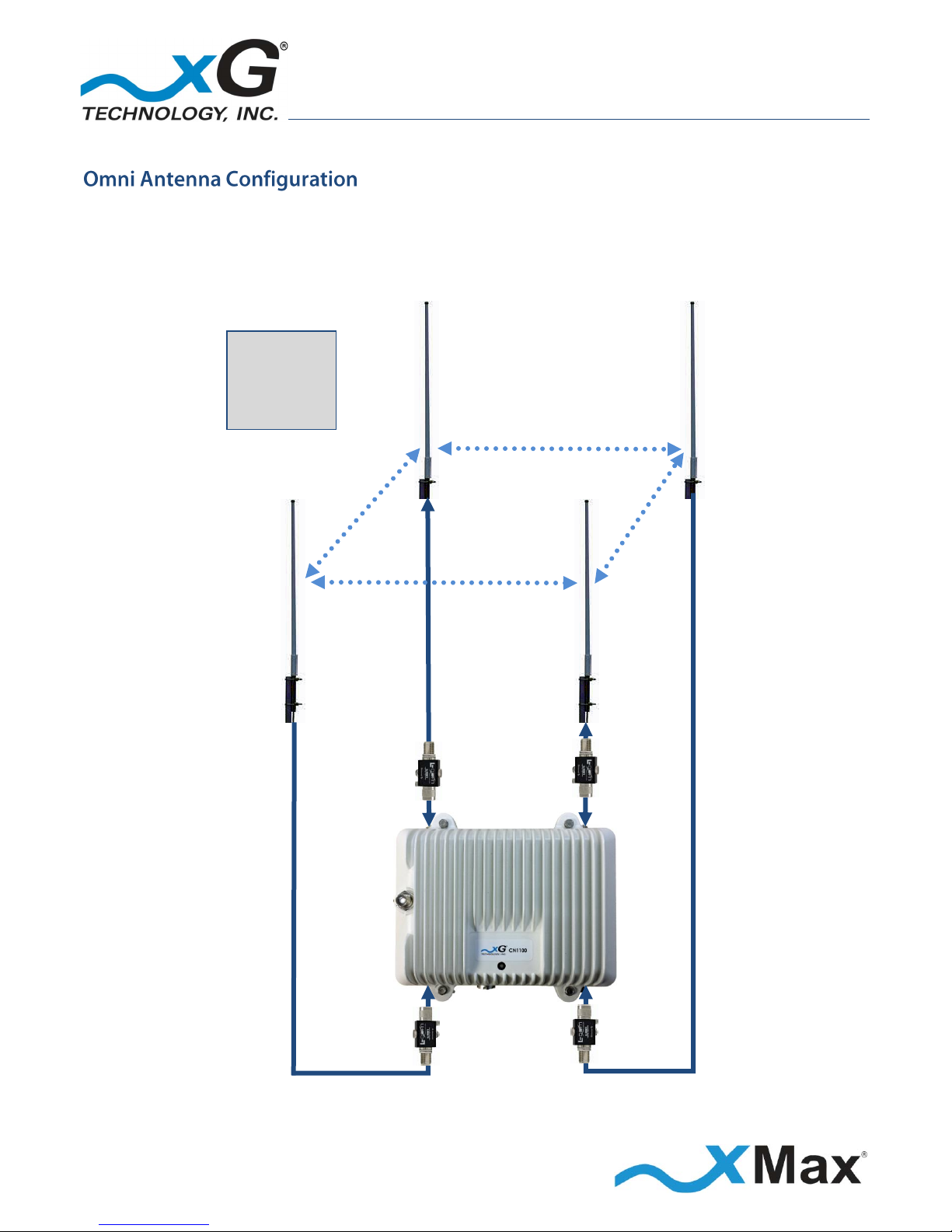
Four antennas are used with an Omni antenna installation. The antennas should be arranged in a
square configuration with two feet (2 ft.) separation on each side. This is the minimum separation
distance required for proper operation.
Omni antenna gain is limited to 5 dBi. The Laird Technologies OD9-5 antenna is approved for use.
VERTICAL
HORIZONAL
Tx1/Rx1
Tx3/Rx3
Rx4
Rx2
HORIZONAL
VERTICAL
Figure 2 — Omni Antenna Configuration
2 feet
(0.6 m)
Each Side
15
CN1100 Access Point - Installation Guide - G7601 - 3.8
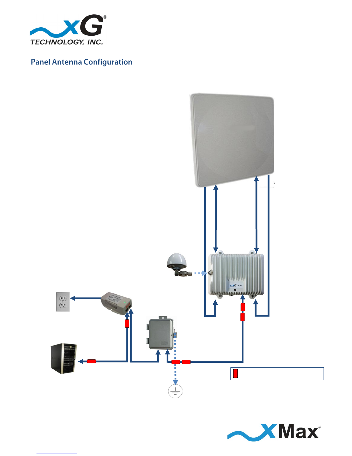
This is a typical tower-mounted CN1100 installation with an xMax KP Performance 2x4 MIMO Panel
Antenna (KPPA-900MHZ4P90S), exclusively supplied by xG. The required parts are listed.
CN1100 PANEL ANTENNA
INSTALLATION PARTS LIST
SUPPLIED BY xG Technology
1 – CN1100 with Mounting Bracket
1 – PoE++ Power Supply
with Power Cord
1 – Weatherproof Ethernet Kit
8 – Ferrite Beads
1 – GPS Antenna (TNC-type)
and right-angle connector
1 – 2x4 MIMO Panel Antenna
4 – Antenna Cables (N-type)
OBTAIN FROM YOUR PART SUPPLIER
3 – Low-Loss Ethernet Cables
(Lengths as required)
1 – PoE Surge Protector
1 – GPS Antenna Cable (If required)
GPS
ANTENNA
110-240 VAC,
50/60 Hz
PoE++
Power Supply
PoE
Surge
Protector
ETHERNET
DATA
POWER
plus DATA
Install Ferrite Beads as shown.
xMCC
Grounded PoE Surge Protector at Building Entry
Figure 3 —Panel Antenna Configuration
Tx/Rx Tx/Rx
V H
V
Rx
H
Rx
16
CN1100 Access Point - Installation Guide - G7601 - 3.8
This procedure should be completed before installing the CN1100 in a service location.
These steps set up the CN1100 Access Point for use. After completing these configuration steps, the
CN1100 Access Point will be fully functional and ready for operation. It broadcasts on the configured
channel and provides any Internet-ready device the ability to connect wirelessly to the xMax
network, using a secure WiFi connection.
A personal computer is used to configure the CN1100 Access Point. The xMax xAP Management tool
is supported and operates on the following platforms:
Operating Systems
Any version of Windows that supports the listed browsers (XP, Vista, 7, 8, 10)
Any version of Linux that supports Chrome or Firefox
Any version of OSX that supports Chrome or Firefox
Browsers
Firefox 3 or later
Internet Explorer 6 or later
Chrome 13 or later
The examples shown in this document present the view using a computer running Windows 7.
NOTE
This sequence assumes that the CN1100 device is in factory-default configuration and has not been
previously configured.
IMPORTANT: BEFORE YOU CONTINUE
Antennas or dummy loads MUST be connected to the two Tx RF ports.
Both Tx RF ports MUST be properly terminated
before power (PoE) is applied to the unit.
Applying power without
proper RF port termination might damage the unit
and void the product warranty.
17
CN1100 Access Point - Installation Guide - G7601 - 3.8
1. Use a laptop or desktop computer to configure the CN1100 Access Point. Configure the computer
network adapter to Internet Protocol Version 4 (TCP/IPv4) for a static IP address and subnet mask.
BEFORE YOU CONTINUE
Be sure to take note of the current network adapter settings to restore them after configuration.
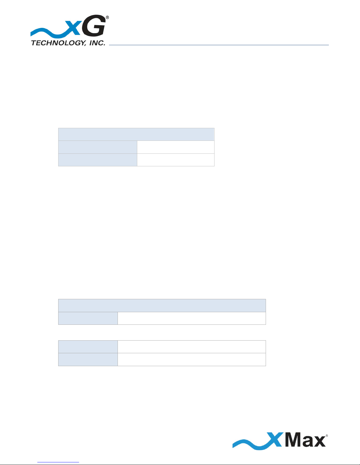
2. Use the IP Address as shown below:
Computer Network Adapter Settings
IP Address:
10.0.0.3
Subnet Mask:
255.240.0.0
3. Connect the AC Power Cord to the PoE++ Power Supply and plug it into an AC power source.
The LED on the power supply glows GREEN.
4. Using an Ethernet cable, connect the computer to the Data (IN) port on the PoE++ Power Supply.
5. Using a second Ethernet cable, connect the Power plus Data (OUT) port on the PoE++ Power Supply
to the Ethernet connector on the CN1100.
The Status LED glows RED within 20 seconds after the power source is switched on.
NOTE
If a GPS antenna with signal is not connected, the LED on the CN1100 slowly flashes RED.
6. On the computer, open a Web browser.
7. In the address line enter the IP address to open the CN1100 Management window:
CN1100 Management
IP Address:
https://10.0.0.3
8. In the Username and Password fields enter:
User name:
admin Password:
admin1
The password is case sensitive.
 Loading...