


Quick Install Guide
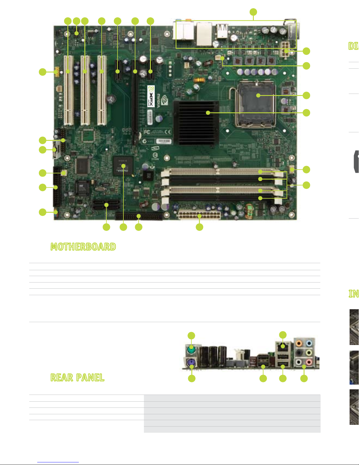
1. CPU Socket
2. NVIDIA SPP with passive heat sink
3. CPU fan connector
4. DDR DIMM Slots 0 - 3
5. 24-pin ATX Power Connector
6. IDE connector
7. NVIDIA MCP
15. PCI slots
16. Front Panel Audio connector
17. PCI Express x1 slot
18. PCI Express x16 slot
19. Back panel connectors
20. 8-pin ATX_12V power connector
8. Serial-ATA connectors
9. Front panel connector
10. Floppy drive connector
11. System fan connector
12. Motherboard battery
13. USB headers
14. Serial connector
MOTHERBOARDMOTHERBOARD
REAR PANELREAR PANEL
INSTALLING THE CPUINSTALLING THE CPU
DIMM SLOTSDIMM SLOTS
1
2
18
20
3
4
5678
5432
1
6
9
14
10
12
13
11
15 15 15 17 171816
19
1. PS/2 Mouse Port
2. PS/2 Keyboard
3. USB 2.0 Ports (two)
4. USB 2.0 ports (two)
5. Audio
6. LAN Port with LED status
indicators
• Yellow/Light Up/Blink = 10 Mbps/Link/Activity
• Yellow and Green/Light Up/Blink = 100 Mbps/link/Activity
• Green/Light Up/Blink = 1000 Mbps/Link/Activity
Port
Blue
Green
Pink
Orange
Black
2-Channel
Line-In
Line-Out
Mic In
4-Channel
Line-In
Front Speaker Out
Mic In
Rear Speaker Out
6 or 8-Channel
Line-In
Front Speaker Out
Mic In
Center/Subwoofer
Rear Speaker Out
5. Audio Configuration
Single Channel
Dual Channel
Memory Configuration
Front Panel Header Pins
RESET
PWRSWBlank
No Connect
9
10
USB Header
Refer to page 12 of the manual in the motherboard installation CD for additional details.
10
8
6
4
2

INSTALLING THE CPUINSTALLING THE CPU
DIMM SLOTSDIMM SLOTS
DIMM Slot 0
DIMM Slot 2
DIMM Slot 1
DIMM Slot 3
Configuration
1
2
3
4
5
6
7
LABEL
HD_LED
PWRLED
RESET
PWRSW
No Connection
Empty
DESCRIPTION
Hard Disk Activity LED
Front Panel Power LED
Reset Switch
Power Switch
PIN
1
2
3
4
5
6
7
8
9
10
DIMM0
Populated
Populated
Populated
DIMM1
Populated
Populated
Populated
DIMM2
Populated
Populated
Populated
DIMM3
Populated
Populated
Populated
Single Channel
Dual Channel
Memory Configuration
Front Panel Header Pins
RESET
PWRSWBlank
No Connect
PWRLED
– +
1
2
9
10
– +
HD_LED
SIGNAL
5V_Dual
DD+
GND
Empty
SIGNAL
5V_Dual
DD+
GND
No Connect
PIN
1
3
5
7
9
PIN
2
4
6
8
10
USB Header
Refer to page 12 of the manual in the motherboard installation CD for additional details.
10
8
6
4
2
9
7
5
3
1
Remove the protective socket cover on the load plate which is used to protect the
socket when there is no CPU installed.
Unhook the socket lever by pushing down and away from the socket.
Lift the load plate.
Align the notches in the processor with the notches on the socket.
Lower the processor straight down into the socket without tilting or sliding it into
the socket.
Close the load plate over the CPU and press down while you close and engage the
socket lever.
There are many different fan types that can be used with this motherboard. Follow
the instructions that came with your fan assembly. Be sure that the fan orientation
is correct for your chassis type and your fan assembly.
3
1
2
4
5
6
7
Align notches with notches on the CPU.

PWRLED – Front Panel Power LED
PWRSW – Power Switch
HD_LED – Hard Disk Activity LED
RESET – Reset Switch
These connectors are for peripherals such as
floppy drive, hard disk drives, and optical drives.
(i.e. DVD-ROM, CD-ROMS, etc)
Note: Drive cables are designed to fit in these
connectors in only one orientation.
Unlock a DIMM slot by pressing the module clips outward.
Match the notch on the memory with the notch on the DIMM slot. Align the memory module to
the DIMM slot, and insert the module vertically into the DIMM slot. The plastic clips at both sides
of the DIMM slot automatically lock the DIMM into the connector.
DIMM Slot
RESET
PWRSWBlank
No Connect
PWRLED
– +
1
2
9
10
– +
HD_LED
INSTALLING MEMORYINSTALLING MEMORY
Refer to page 13 of the manual in the motherboard installation CD for additional details.
CONNECTING FRONT PANEL HEADERCONNECTING FRONT PANEL HEADER
Refer to page 19 of the manual in the motherboard installation CD for additional details.
CONNECTING DISK DRIVESCONNECTING DISK DRIVES
Refer to page 17 of the manual in the motherboard installation CD for additional details.
POWER CONNECTIONPOWER CONNECTION
Refer to page 16 of the manual in the motherboard installation CD for additional details.
1
2
Note: In general white and black wires are the negative leads (-) and the other colored
wires are the positive (+) leads. LED will not work if the negative and positive leads are
plugged in backwards.
SATA
Connectors
Floppy
Connectors
EIDE
Connectors
*The quick guides are used only for reference, please refer to the installation manual for detailed installation procedures.
This motherboard requires an ATX power supply.
Note: Power supply cables are design to fit the motherboard power
connectors in only one orientation.
• For general motherboard setup, make sure the 24-pin
ATX power connector, and the 8-pin 12V power
connector are properly connected to the power supply.
8-pin ATX 12 Power
Connector (PWR2)
24-pin ATX Power
Connector (PWR1)
To set up Raid using NVIDIA MediaShield Storage, refer to the manual in the motherboard installation CD.
(Page 82).
Please refer to the manufacture’s installation manual when installing any devices (i.e. graphics boards,
hard disk drives, optical drives, etc.) to the motherboard.
 Loading...