

X-Factor X–60 Assembly Instructions Manual
–
0
X – 60 ASSEMBLY
www.2wdrc.com
INSTRUCTIONS
Version 1.0
X
X – 60 Instructions Version 1.0 Page 1
6
CONVERSION KIT

TABLE OF CONTENTS
T4 Disassembly………………………………………………………….... 5
Bag A – Transmission Assembly………………..………………………. 12
Front End Installation……………………………………………………… 17
Bag B – Bulkhead & Transmission Install ……………………………… 20
Bag C – Rear Suspension Assembly…….……………………………… 25
Bag D – Final Assembly………………………………………………….. 29
Tuning Section……………………………………………………………… 33
X – 60 Instructions Version 1.0 Page 2

X – 60 ASSEMBLY INSTRUCTIONS
FIRST THINGS FIRST
A) ASSUMPTIONS These instructions assume several things:
1. You have at least some experience building R/C cars. These
instructions are not written for a first-timer.
2. You have the usual assortment of R/C tools.
3. You have a Team Associated RC10 T4 rolling chassis, any model.
If you do not meet all the assumptions above, please contact us
immediately. Contact information is on Page 4.
WE WANT YOU TO HAVE A PLEASANT EXPERIENCE
BUILDING THIS KIT, AND HOPE YOU HAVE MANY
PLEASURABLE DAYS DRIVING YOUR NEW X- 60. Please
contact us with the slightest problem. We want to help. Talking
with the Family is so much more fun than work.
B) We suggest you have a clean, well-lighted work area with enough space
to simultaneously do three things: Work on the car; Store sub-
assemblies for later use; Store parts which will no longer be needed.
C) Before threading in screws, tap all holes with a 4-40 tap.
D) You will want to re-build many components, for example shocks, or to
disassemble some assemblies for inspection and cleaning. We include
no instructions for this – refer to your T4 manual.
E) All references to right and left are from the viewpoint of the driver sitting
in the car facing forward.
F) Throughout this manual the names of many parts are followed by a
number in parenthesis. This is the AE part number.
G) To photograph this manual, we assembled the truck several times. In
some photos, parts you have already assembled are “missing.” We
have done this deliberately so you may clearly see this particular step.
Follow the steps in order and you’ll get to the end quickly.
Most important, a big “thank you” to Chris Krieg, father of Team driver Alex,
who assembled his X – 60 at least three times to take the great photos and
wrote many of the instructions. Thank you, Chris!!!
X – 60 Instructions Version 1.0 Page 3

SOME IMPORTANT INFORMATION
This is our third Kit, and we know we are not perfect. If you experience the
slightest difficulty assembling your X – 60, either because a part does not fit
properly or because you have difficulty with the instructions, please contact us
immediately. Even if you figure out what needs to be done, or make a
modification that allows the part to fit, we want to make changes that help the
next person.
You are much more than a customer at X Factory. You have become a member
of a world-wide Family of R/C racing enthusiasts who love working on their cars,
trying new things, and helping others at the track. We communicate with our
Family constantly, and the Family gives us ideas every day for new products and
improvements on existing products. We welcome and encourage this input.
Contact us by: E-mail: chazz@2wdrc.com
Snail mail: X Factory R/C Racing Products
P.O. Box 2361
Whitehouse, Ohio 43571
Phone: 419-887-1787 (USA)
Thanks in advance for your help!
These instructions are available on our web
site, www.2wdrc.com . The photos are in
color. In many instances, the color photos
on the web are better than the black and
white in this printed manual.
THANK YOU FOR YOUR
CONFIDENCE IN THE X – 60
Photographer and
Instruction-writer
Chris Krieg (Large Arrow)
His X – 60 (Small Arrow)
X – 60 Instructions Version 1.0 Page 4
WELCOME TO THE X FACTORY FAMILY!!
X - 60 INSTRUCTIONS
T4 DISASSEMBLY
FRONT END
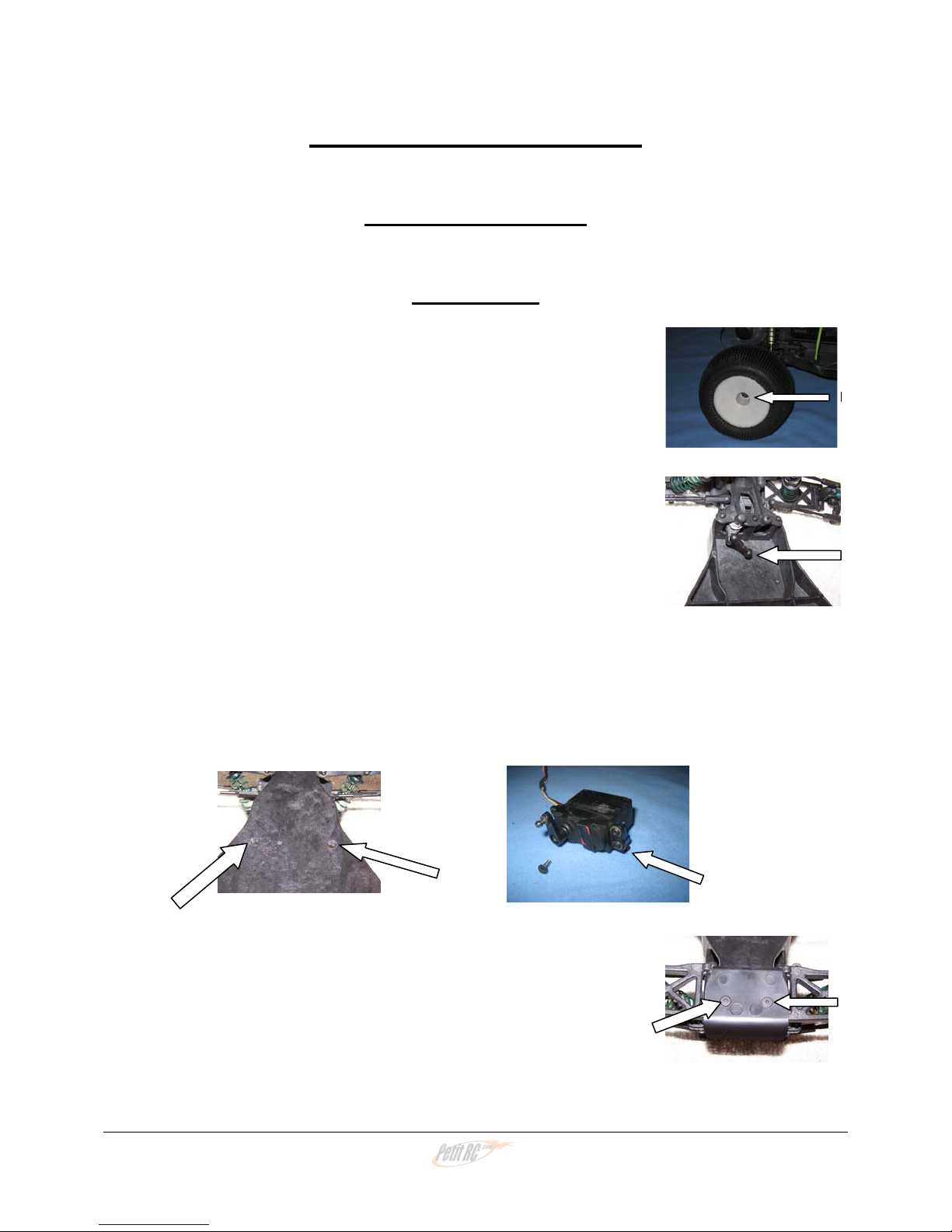
1) Remove the body. Save all the body clips for re-use.
Remove the front wheels. Leave the wheel bearings
inside the wheels. Save the wheels and nuts for re-use.
2) Disconnect the servo link from the servo horn. Leave it
connected to the steering bell crank.
3) Remove the two flat head screws from under the chassis that hold the servo in,
and remove the servo. Leave the servo horn and the two servo mounts
attached. Save the two flat head screws that hold the servo in for re-use. Want
to make sure you don’t lose the two screws? Put them a few turns back in the
holes they came from – they’ll be right there later.
4) Remove the two flat head screws that hold on the front
bumper. Take off the bumper. Save it and the two
screws for re-use.
X – 60 Instructions Version 1.0 Page 5
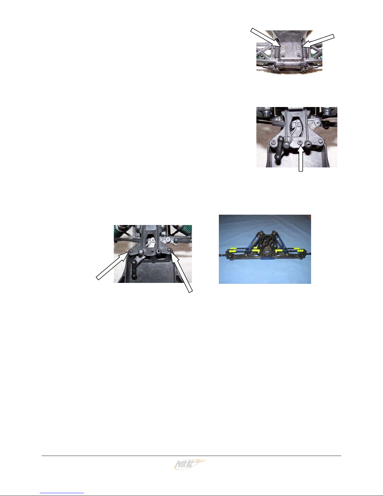
5) Remove the two flat head screws which hold the
bulkhead to the chassis. Save them for re-use.
6) From the top of the truck, remove the center screw
holding the top plate to the post on the T4 chassis.
Save the screw for re-use.
7) Remove the two side top plate screws. Save them for re-use. Carefully remove
the front end and steering assembly, and set it aside for re-use. Make sure the
steering linkage stays in place.
That’s it! Let’s do the rear of the truck.
X – 60 Instructions Version 1.0 Page 6
REAR CVDs & HUB CARRIERS
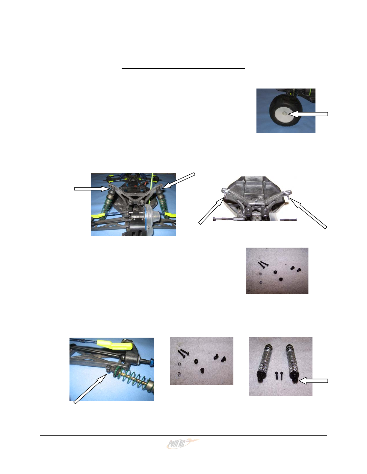
8) Remove the wheels and tires. Save them and the
nuts for re-use.
9) Remove the two nuts that hold the top of the rear shocks on. Save them for re-
use. Slide the shocks off the bolts, and save the mounting bushings for re-use.
10) Remove the nuts that hold the shock bolts in the
tower. Remove the bolts, and save the bolts, nuts,
bushings and plastic nuts for re-use.
11) Remove the bolt that holds the bottom of each rear shock to the rear control arm.
Set the shocks and bolts aside for re-use. Do not lose the bushing in the bottom
shock eyes.
X – 60 Instructions Version 1.0 Page 7
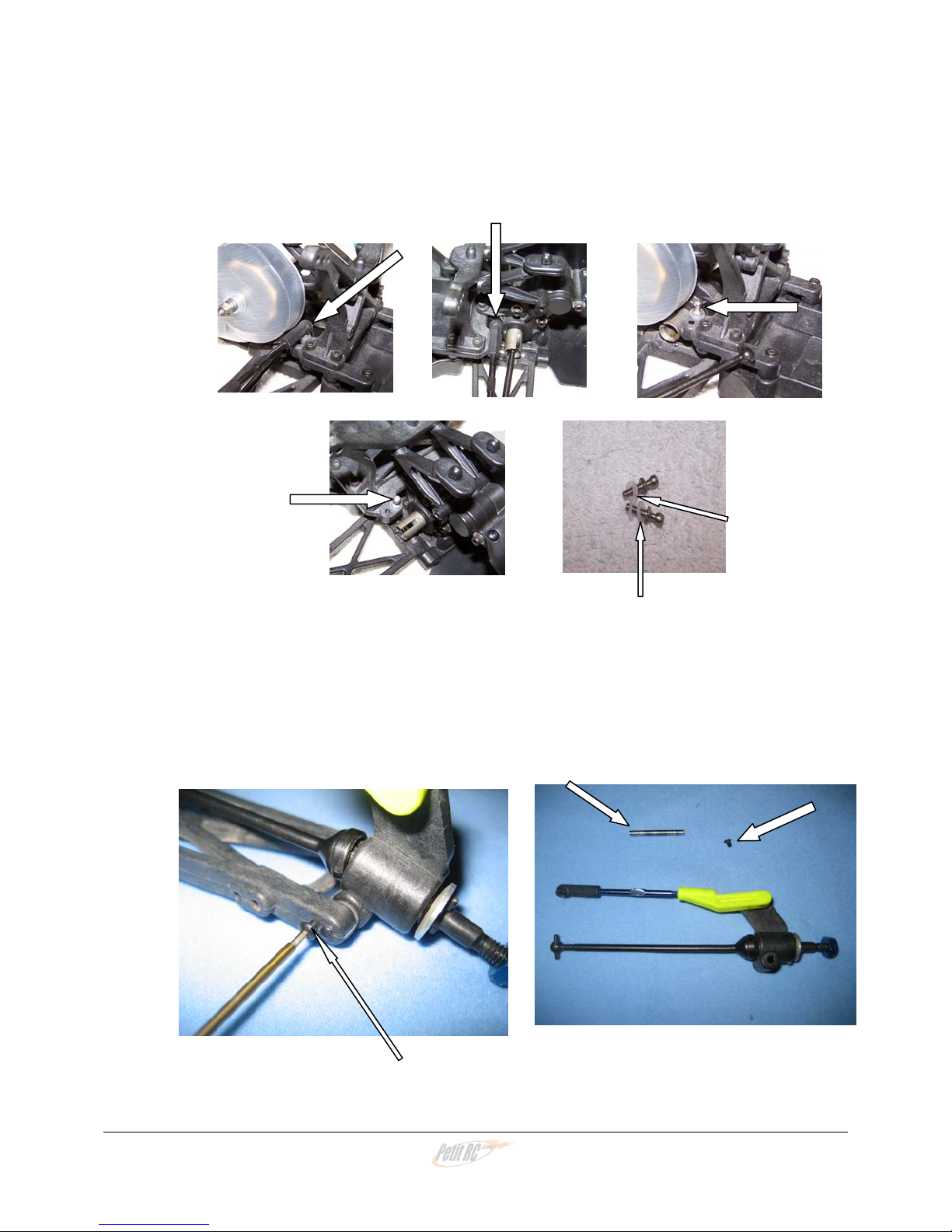
12) Remove the inner camber link ball cups from their studs. Leave them attached to
the turnbuckle and leave the other end of the link attached to its ball stud at the
hub carrier. Then remove the ball studs. Save the ball studs and any washers
that were under them for re-use.
13) From the outside end of the front of the rear control arm, remove the little 2-56
screw that holds in the hub carrier. Don’t lose it! Now, from the rear of the
control arm, use your wrench to push the hinge pin forward so you can remove
the pin. The hub carrier, with camber link and CVD assembled, will fall off. Save
the spacers. Set all these parts, hub carrier assembly, hinge pin, spacer(s) and
little screw, aside for re-use.
14) Repeat for the other side.
X – 60 Instructions Version 1.0 Page 8
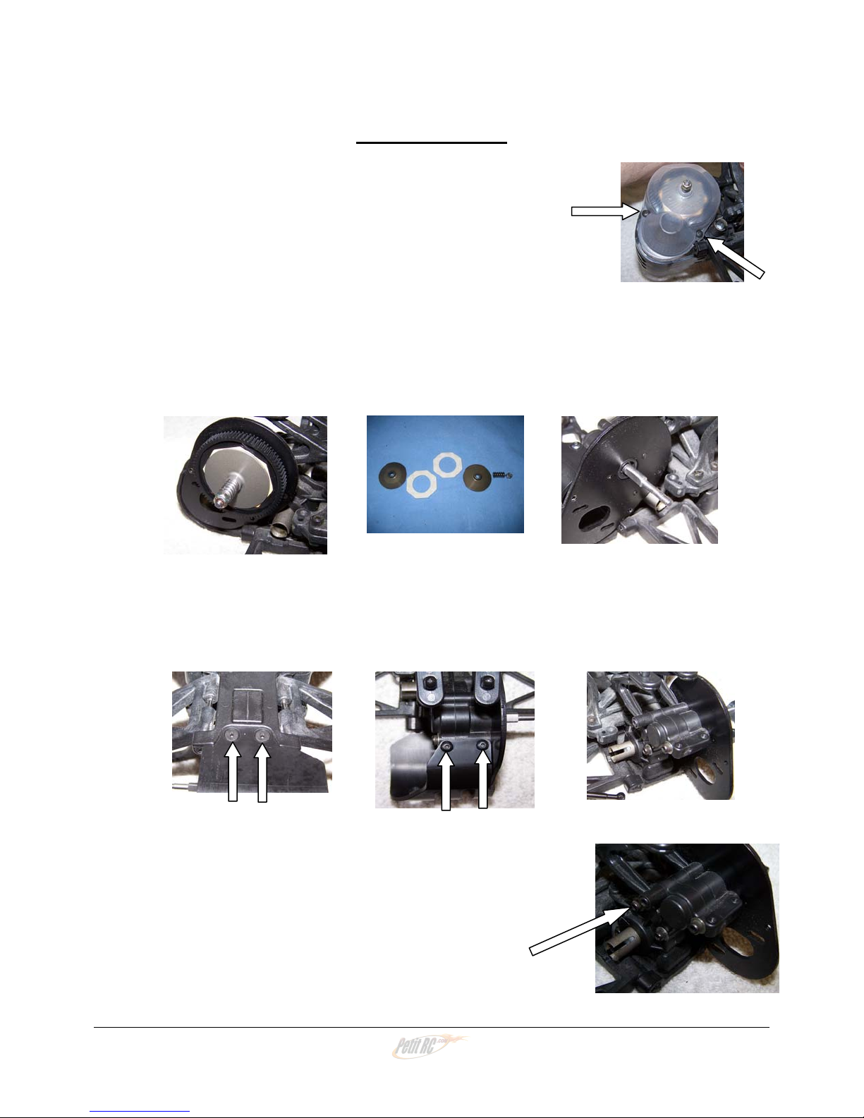
TRANSMISSION
15) Remove the two button head screws that secure the gear
cover. Remove the cover. The cover and screws will
not be needed.
16) Remove the slipper nut, then the spring, slipper plate, slipper pad, spur gear,
inside slipper pad, and inside slipper plate. You will not need the spur gear, but
you must save all the other parts for re-use.
17) From under the truck remove the two flat head screws that hold the motor guard.
Then, from above, remove the two button head screws that hold the motor guard
to the top rear of the transmission. The motor guard and the two button head
screws will not be needed. Save one flat head screw for re-use in B-11.
18) Remove the long bolt through the transmission that
holds the body mounts. This bolt will not be needed.
X – 60 Instructions Version 1.0 Page 9
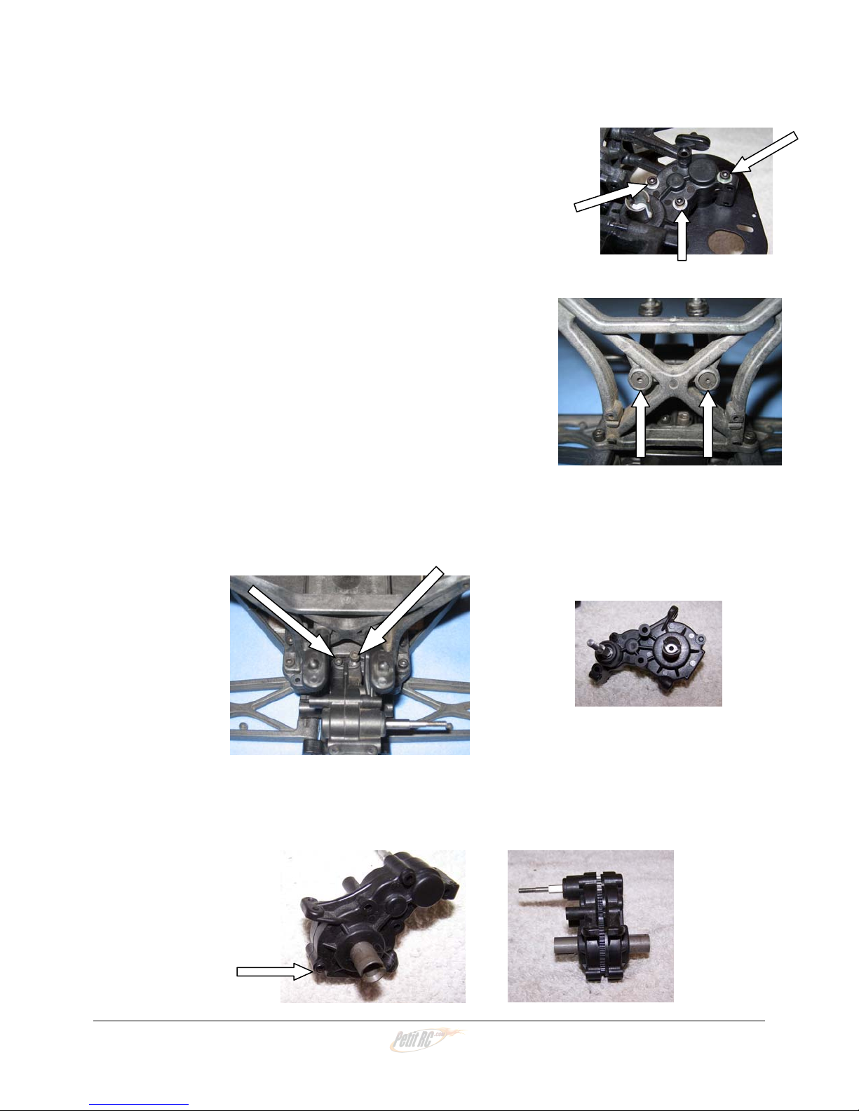
19) Remove the three bolts that go through the transmission
and hold the motor plate on. Save these bolts for reuse
in A-12; the plate will not be needed.
20) Two flat head screws hold the body mounts on from
the front of the tower. You may remove them and
the mounts if you wish, or just loosen and twist the
mounts out of the way for step 21.
21) From the top, put your wrench down between the body mounts and remove the
two cap head screws that secure the transmission to the shock tower. You
should now be able to remove the transmission from the truck. Save the screws
for re-use in D-2.
22) Remove the bottom bolt that holds together the two halves of the transmission
case and carefully separate the case halves. Save this bolt for re-use in A-10.
X – 60 Instructions Version 1.0 Page 10
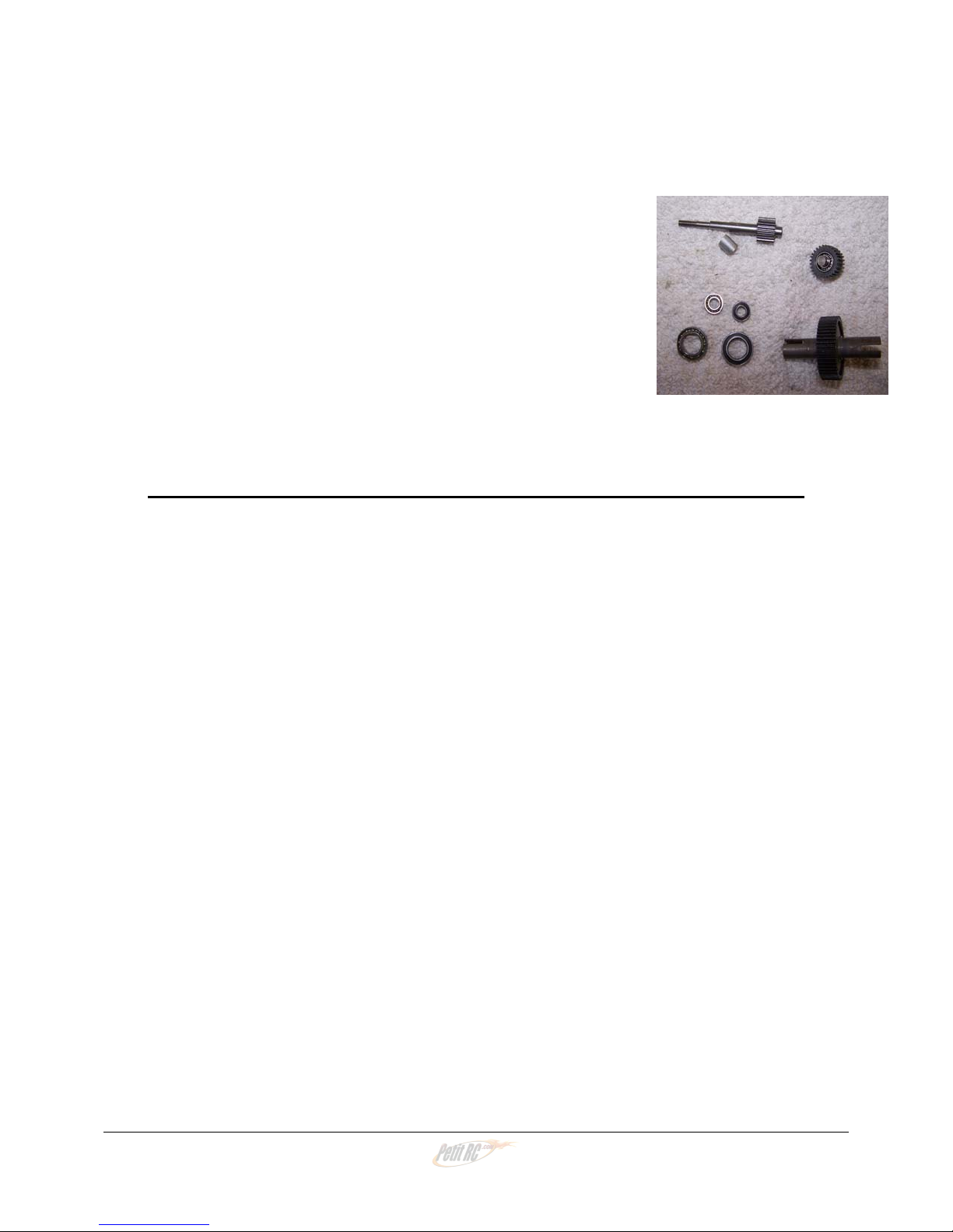
23) As the case halves come apart, remove and save all of
the following parts: Top shaft, spacer, and two 3/8 X
3/16 bearings, Idler gear, two more 3/8 X 3/16 bearings,
& idler shaft, Ball differential and two ½ X 5/8 outdrive
bearings. You will need all the parts from inside the
transmission but the two case halves will not be
needed.
That’s it! You have now removed all the parts needed to build your X - 60!
X – 60 Instructions Version 1.0 Page 11
 Loading...