

READ ME FIRST
1-22-88
THANK YOU for purchasing the Lt. Kernal. Please read the following before proceeding.
1.
Make sure that all functions of your computer system are working
properly before adding the Lt. Kernal Disk drive to your system
because any problems that your system might have, could be seen
as Lt. Kernal problems after it is installed.
2.
READ the Lt. Kernal manual thoroughly before doing any installa-
tion.
Do not assume anything. See Section II, pages 2-1 through 2-20.
3.
Do not attempt any of the installation work with the power on. Do
not connect anything to your computer with the power on.
4.
When doing the internal hook-up on your computer, DOUBLE
CHECK the connections before closing the computer.
5. If all of
with the steps in the manual to bring your Lt. Kernal to life. See Sections m and on.
6. Most problems encountered on an initial system boot are due to having a C-128 computer system set for an 80 column display. This will
result in a Commodore sign-on message with no apparent activity from
the Lt. Kernal. This is due to the fact that the Lt. Kernal is shipped
to boot-up in the 64 mode (40 column display). Simply make sure
that both the monitor and computer are set to 40 column operation
OR change the boot-up default to C-128 mode with the CONFIG
command.
7. If you have carefully followed the instructions, your Lt. Kernal should
be running and ready for your use. If it is not functioning, re-check
the installation
8. After you have the system running, become familiar with it before
making changes. Learn how to use the simple commands before attempting a system CONFIGuration, for example.
9. DO NOT DO a SYSGEN unless absolutely necessary. Read the
REPLACEMENT pages 2-25 and 2-26 tided THE SYSGEN UTILITY to determine when and how to do a SYSGEN.
the
above has been done properly, you are ready to continue
and
refer
to
the Trouble Shooting section of the manual.
10.
When making changes, record the condition the system was in prior
to making the changes.
11.
Most Users get into trouble
are doing, and then question the need to do it.
12.
If you have any doubts, call us or check into the BBS for help. The
BBS is listed on page A-7 of your manual.
13.
If possible, save the box and packing material your unit was shipped
in.
This box was designed to safely ship the Lt. Kernal.
assuming.
Make sure you know
what
you


Lt. Kernal
20 or 40 Megabyte Systems
Operating
Manual
Lt. Kernal is a registered trademark of Fiscal Information, Inc.

LIMITED WARRANTY
Xetec, Inc. warrants this Xetec hard disk drive known as the Lt.
Kernal, to be in good working order for a period of one year from the
date of purchase from Xetec, Inc. or an authorized Xetec dealer.
Should this product fail to be in good working order at any time during this one year warranty period, Xetec will at its option, repair or
replace this product at no additional charge except as set forth below.
Repair parts and replacement products will be furnished on an exchange basis and will be either reconditioned or new. All replaced
parts and products become the property of Xetec, Inc. This limited
warranty does not include service to repair damage to the product
resulting from accident, disaster, misuse, abuse, or non-Xetec
modification of the product.
Limited warranty service may be obtained by delivering the product
during the one year warranty period to an authorized Xetec dealer or
to Xetec, Inc., and by providing proof of purchase date. Warranty will
be valid for registered owners only. If this product is delivered by
mail, you agree to insure the product or assume the risk of loss or
damage in transit, to prepay shipping charges to Xetec, Inc., and to
use the original shipping container or equivalant. Contact Xetec,
Inc.,
2804 Arnold Rd., Salina, Ks.
information.
67401,
(913)827-0685 for further
All express and implied warranties for this product including the warranties of merchantability and fitness for a particular purpose, are
limited in duration to a period of one year from the date of purchase,
and no warranties, whether expressed or implied, will apply after this
period. Some states do not allow limitations on how long an implied
warranty lasts, so the above limitations may not apply to you.
If this product is not in good working order as warranted above, your
sole remedy shall be repair or replacement as provided above. In no
event will Xetec be liable to you for any damages including any lost
profits, lost savings or other incidental or consequential damages arising out of the use of, or inability to use such product, even if Xetec or
an authorized Xetec dealer has been advised of the possibility of such
damages, or for any claim by any other party.
Some states do not allow the exclusion or limitation of incidental or
consequential damages for consumer products, so the above limitations
or exclusions may not apply to you.
This warranty gives you specific legal rights, and you may also have
other rights which may vary from state to state.
TABLE
The Lt. Kernal preface v
OF
INTRODUCTION
CONTENTS
FCC Statement
The Lt. Kernal 1-1
DOS features
Technical specifications
Installation 2-1
Power voltage
Physical handling precautions
Equipment installation
C-64 installation
C-128 installation
128D installation
Burst Mode Modification
I/O Modification
Power Application
vi
SECTION I
1-1
1-2
SECTION II
and
frequency
2-1
for CP/M 2-18
and
Removal
2-1
2-1
2-3
2-7
2-12
2-14
2-20
SECTION III
Activating the System 3-1
What
to
expect
Operating Concepts 4-1
How
the Lt.
Operating limitations
Commands Overview 5-1
Run-mode commands
Direct-mode commands
Review
Syntax Definitions and Conventions 6-1
of
3-1
SECTION IV
Kernal works
4-1
DOS features
4-1
SECTION V
5-1
5-1
5-2
SECTION VI
I
SECTION VII
Run-mode Features and Commands ..
command page
autoaccess feature
autostart feature 7-2
bell feature
BUILDKEY file
COPY
DELETE key
INSERT key 7-6
LDLU
LG
LOAD
OPEN
SAVE
SCRATCH 7-12
SEARCH for key 7-13
SHUFFLE key file directory
SECTION VIII
Direct-Mode Features and Commands.
7-1
7-1
7-3
7-4
8-13
7-5
7-7
7-8
7-9
7-10
7-11
7-14
8-1
command page
Tt
(restore defaults)
8-1
ACTIVATE 8-2
AUTOCOPY
8-3
AUTODEL 8-4
AUTOMOVE
BUILD
BUILDCPM
BUILDINDEX
CHANGE
8-5
8-6
8-7
8-8
8-9
CHECKSUM 8-10
CLEAR
CONFIG
COPY
D (change drive if)
8-11
8-12
8-13
8-14
DELete BASIC lines 8-15
DI (dump key file directory) 8-16
File type definitions 8-16
DIRectory 8-17
DUMP BASIC to text 8-19
ERAse file
8-20
FASTCOPY backup utility 8-21
FETCH text to BASIC 8-22
FIND
8-23
ii

Direct-Mode Features and Commands
G064 8-25
GO 128
GOCPM 8-27
ICQUB capture utility 8-28
Invoke feature 8-30
L (abbrieviated LOAD)
LOAD 8-31
LKOFF
LKREV 8-33
LU (change logical unit
MERGE 8-35
OOPS (recover erased file)
QUERY 8-37
RECOVER 8-38
RENUMber BASIC programs 8-39
S (special save) 8-45
SAVE program
SHIP (prepare drive
TYPE disk BASIC
UPDATEDOS
USER (change subdirectory) 8-50
VALIDATE 8-51
to
#)
disk 8-46
to
ship) 8-47
to
screen 8-48
continued
8-26
8-31
8-32
8-34
8-36
8-49
SECTION
Programming Considerations
General precautions 9-1
Backup copying 9-2
Directly invoked applications 9-4
Stack manipulations 9-5
Reserved memory areas 9-5
Speed tips 9-6
Disk partitioning 9-6
KEY FILES
KEY file usage
Definitions
KEY file structure 9-7
Simple
KEY file constraints 9-11
DIRECTORY lengths
KEY Run-mode values 9-13
KEY command mode values
KEY command parameters 9-14
KEY command general status returns 9-15
BUILDKEY file command 9-15
Machine Language
of KEY
KEY
file terminology 9-7
file examples
vs KEY
key
file access 9-16
IX
9-1
9-7
9-8
lengths
9-12
9-14
iii
Programming considerations
INSERT
DELETE
SHUFFLE directory command
SEARCH commands
The CONFIG processor
The SYSGEN utility
key
key
command
command
9-17
9-19
9-21
9-25
continued
9-18
9-18
SECTION
Addenda/Errata
and
Update Documentation
SECTION
Trouble-Shooting
Trouble-shooting guide
Functional tests
Equipment return policy
and
Warranty Service
11-1
11-2
11-5
SECTION
DOS System Enhancements
Obtaining updates
'BUG' reporting
'BUG' reporting form
12-1
12-1
12-1
12-2
SECTION XIII
Installing CP/MTM 0n the Lt.
Using
Building
Operating Speed
CP/M 13-1
CP/M 13-1
13-3
X
XI
XII
Kernal
10-1
11-1
^
13-1
Lt. Kernal Networking
DIAG command
KEY File Programming Example
Bulletin Board
20/40
Index
Meg
X-l
A-7
Add-on Drives
SECTION
XIV
14-1
SECTION
XV
15-1
APPENDIX
I
A-l
APPENDIX
APPENDIX
II
III
A-8
iv
The Lt. Kernal
Welcome to the world of Serious Computing!
PLEASE READ THIS MANUAL CAREFULLY
BEFORE ATTEMPTING TO INSTALL YOUR LT. KERNAL!
If the first few pages of section II of this manual seem a little stern,
please understand — we want you to have the BEST possible service
from your Lt. Kernal. The only way to let you know about the potential for damage you could do to your system is to tell it like it is!
You've invested in the most advanced disk system available for
Commodore™ computers, and an incorrect installation may damage
the Lt. Kernal, your computer, or both. Read the installation portion of this manual carefully before connecting together any parts of
the system.
The Lt. Kernal results from eighteen years of experience in designing
large multi-user, multi-tasking mini-computer systems. We have applied the technology used in those larger systems to improve the
operating characteristics and speed of the C-64® and C-128® .
Thank you for purchasing the Lt. Kernal. You now have at your
fingertips really high speed computing power and a comfortable, userfriendly disk operating system that significantly upgrades the functions
and usability of your Commodore computer. Quality software written
with the user in mind, and rugged, conservatively designed hardware
are combined to produce the best accessory ever for Commodore
computers.
Lt. Kernal is a registered trademark of Fiscal Information, Inc.
C-64 and C-128 are reg. TM of Commodore Business Machines, Inc.
v
FCC STATEMENT
This equipment generates and uses radio frequency energy and if not
installed and used properly, that is, in strict accordance with the
manufacturer's instructions, may cause interference to radio and television reception. It has been type tested and found to comply with the
limits for a Class B computing device in accordance with the specifications in Subpart J of Part 15 of FCC Rules, which are designed to
provide reasonable protection against such interference in a residential
installation. However, there is no guarantee that interference will not
occur in a particular installation. If this equipment does cause interference to radio or television reception, which can be determined by
turning the equipment off and on, the user is encouraged to try to cor-
rect the interference by one or more of the following measures:
• Reorient the receiving antenna
• Relocate the computer with respect to the receiver
• Move the computer away from the receiver
• Plug the computer into a different outlet so that computer and
receiver are on different branch circuits.
If necessary, the user should consult the dealer or an experienced
radio/television technician for additional suggestions. The user may
find the following booklet prepared by the Federal Communications
Commission helpful: "How to Identify and Resolve Radio-TV Interference Problems." This booklet is available from the U.S. Government Printing Office, Washington, D.C., 20402, Stock No.
004-000-00345-4.
MANUFACTURER'S WARNING: Using a cable between the "Host
Adaptor" and the "Hard Drive Assembly", other than that provided
by Xetec Inc. may result in interference to radio and television
reception.
vi
I
The Lt. Kernal Disk Operating System V7.1
DOS FEATURES
Runs certain copy-protected software
Built-in KEYED INDEXED-RANDOM ACCESS METHOD
Supports both C-64 and 128 modes of operation and CP/M®
58 additional or enhanced system commands and features
Disk access speed more than 100 times faster than the 1541 floppy
Automatic power-up execution of any application program
Built in CP/M™ - like command-line features in C-64 and 128 modes
User configurable system characteristics such as screen and character
colors, and logical drive sizes
Up to eleven logical drives may be defined on the hard disk
Up to 7 hard drives in one system
DOS allows up to seven files to be OPEN for reading and writing
simultaneously in addition to the command/error channel
DOS differentiates between BASIC and machine language programs
Built-in backup and restore facilities
Direct invocation of programs from the READY prompt
Standard capacity of 20 Megabytes configurable up to 140 Meg.
Optional Multiplexer allows up to 16 computers to share 1 Lt.
Kernal system
1-1

TECHNICAL SPECIFICATIONS
Standard capacities, Formatted
Bytes per sector
20 Megabytes
512
Sectors per track 17
Tracks per cylinder
4
Number of cylinders 626
Media size
Recording density
5'/4" (13.3 cm)
10,200 Bits/inch
Track density 300 tracks/inch
Transfer rate to C-64 memory
38,000 Bytes/sec
Transfer rate to C-128 memory 65,000 Bytes/sec
Rotational speed
3,600
RPM
Average latency time 8.3 ms
Positioning time
18 ms min.
192 ms max.
Power consumption
20 Meg. SCSI Drive unit
117 Volts A.C. 60 Hertz 30 w typical
Host Adaptor
+ 5 Volts D.C. 250 ma typical
Size
20 Meg. SCSI Drive unit
Weight
20 Meg.SCSI Drive unit 10.80 lbs.
40 w max.
12"
x 14" x 2.5
1-2
II.
INSTALLATION
CAUTION!
Unless your Lt. Kernal hard disk system is specifically labeled
otherwise, your system has been factory wired for:
115 volts A.C. 60 hertz only
Do not plug the power cord into any other voltage or frequency
outlet.
For domestic American systems, the correct outlet type is the
three prong grounded variety. Use of a three prong adapter in a
two prong ungrounded outlet is strongly discouraged since such
use presents a high shock hazard and may damage your system.
CAUTION!
Always handle your hard disk/power supply assembly with the utmost
care.
Mechanical bumps and shocks to the drive could irrepairably
damage it.
Never move or ship the drive without first conditioning it for shipping
via the "ship" system command, described later in this manual.
Never move the drive unless power has been off for at least 30
seconds.
Never ship the drive in any container except its original carton.
INSTALLING THE LT. KERNAL
Installation of the Lt. Kernal hardware takes only a few moments, but
MUST be done carefully to avoid damage. For a typical system setup
refer to FIG 1. Be gentle, and work slowly and deliberately, referring
to the text frequently as you go.
2-1
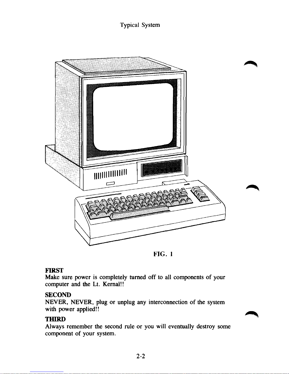
Typical System
FIRST
Make sure power is completely turned off to all components of your
computer and the Lt. Kernal!!
SECOND
NEVER, NEVER, plug or unplug any interconnection of the system
with power applied!!
THIRD
Always remember the second rule or you will eventually destroy some
component of your system.
FIG. 1
2-2
BEFORE BEGINNING YOUR INSTALLATION OF THE
LT.
KERNAL, CAREFULLY CHECK YOUR COMPUTER FOR
PROPER OPERATION WITHOUT THE LT. KERNAL
INSTALLED. THIS WILL PREVENT FALSE
INDICATIONS OF TROUBLE LATER.
There are two possible installations of the Lt. Kernal. One is for the
C-64 computer, and the other for the C-128. To utilize the 128 mode
in the C-128, the C-128 adaptor board must be installed. Both installations will void your computer's warranty, as you will be required to
open the computer case install clips and/or an adaptor board. If you
do not feel competent to do this installation properly, seek the
assistance of a qualified computer technician. CAUTION: Read each
step thoroughly first before proceeding.
TOOLS REQUIRED: A #1 phillips screwdriver and possibly a T-10
TORX driver plus needle nose pliers for the 64C inner shield and a
small flat blade screwdriver.
C-64 or C-64C INSTALLATION
Step 1 - Remove screws on the bottom of the computer case, un-snap
the upper keyboard section and carefully unplug the keyboard and indicator LED cables. Place this section aside for now.
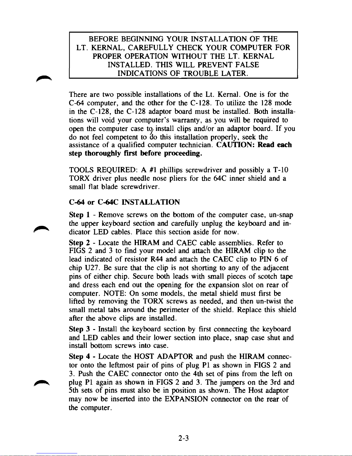
Step 2 - Locate the HIRAM and CAEC cable assemblies. Refer to
FIGS 2 and 3 to find your model and attach the HIRAM clip to the
lead indicated of resistor R44 and attach the CAEC clip to PIN 6 of
chip U27. Be sure that the clip is not shorting to any of the adjacent
pins of either chip. Secure both leads with small pieces of scotch tape
and dress each end out the opening for the expansion slot on rear of
computer. NOTE: On some models, the metal shield must first be
lifted by removing the TORX screws as needed, and then un-twist the
small metal tabs around the perimeter of the shield. Replace this shield
after the above clips are installed.
Step 3 - Install the keyboard section by first connecting the keyboard
and LED cables and their lower section into place, snap case shut and
install bottom screws into case.
Step 4 - Locate the HOST ADAPTOR and push the HIRAM connector onto the leftmost pair of pins of plug PI as shown in FIGS 2 and
3.
Push the CAEC connector onto the 4th set of pins from the left on
plug PI again as shown in FIGS 2 and 3. The jumpers on the 3rd and
5th sets of pins must also be in position as shown. The Host adaptor
may now be inserted into the EXPANSION connector on the rear of
the computer.
2-3

C-64 cable connections version 2
You may have a newer version of the C64 computer board that is smaller
at about 5" wide. Use the information below to make your HIRAM and
CAEC connections.
HIRAM cable to pin 28 of U6 (MPU) or to pin 6 of U8 (PLA)
CAEC cable to pin 5 of U6 (MPU) or to pin6 of U3.
2-5
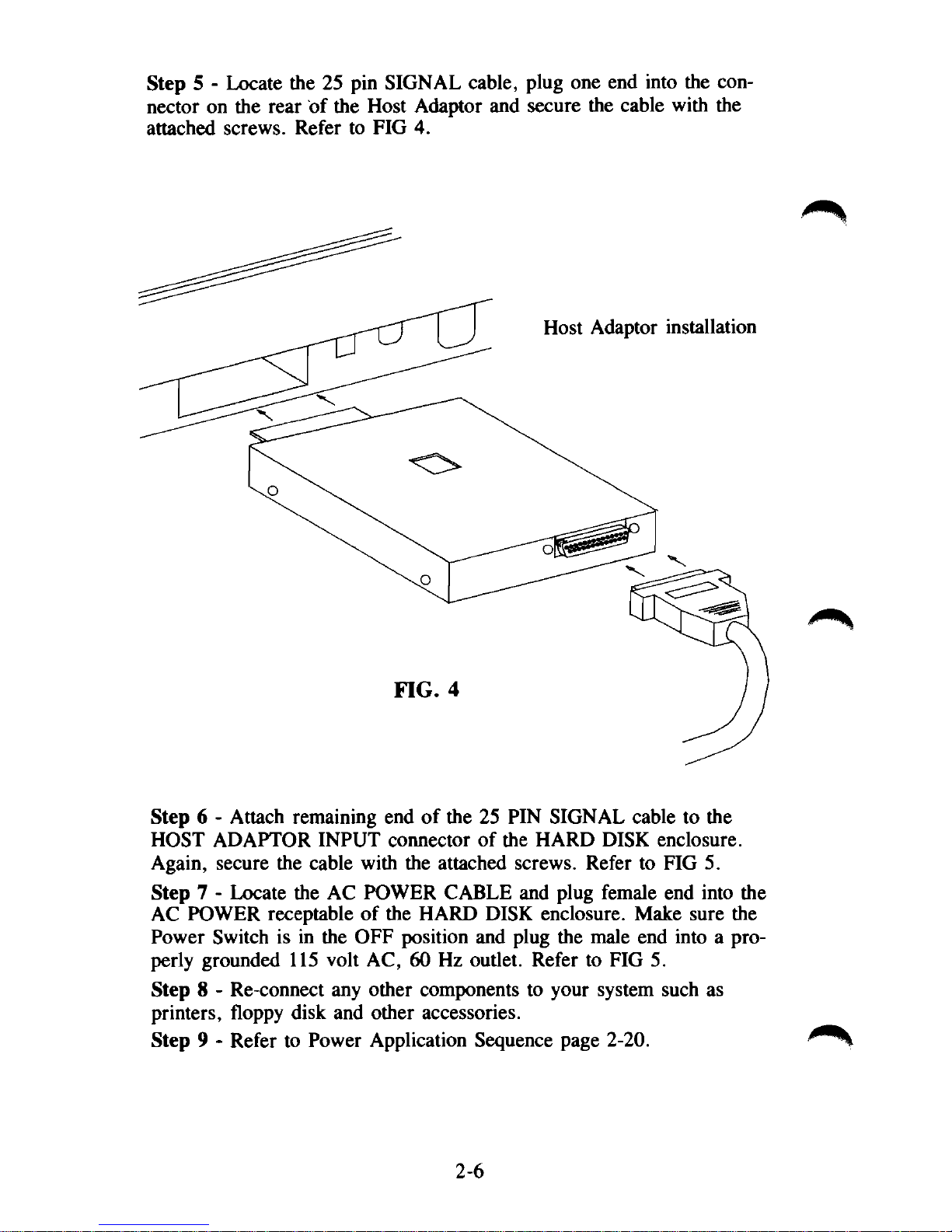
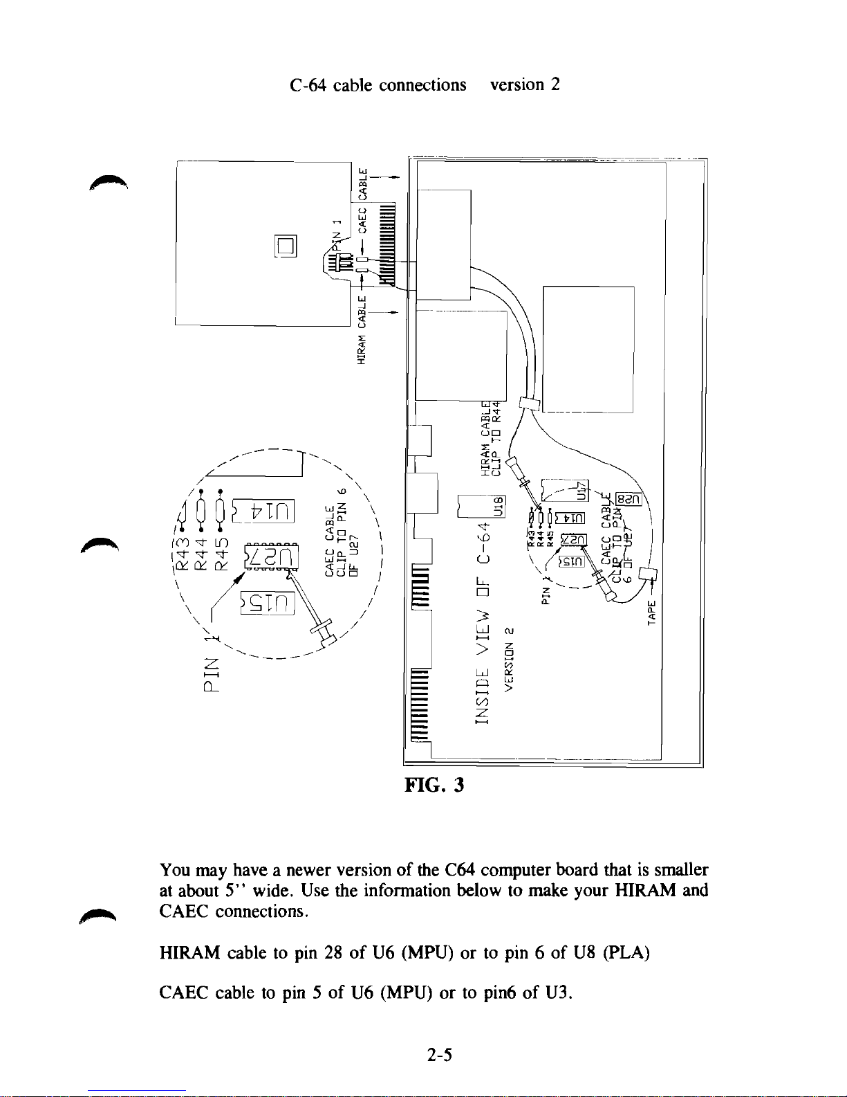
Step 5 - Locate the 25 pin SIGNAL cable, plug one end into the connector on the rear of the Host Adaptor and secure the cable with the
attached screws. Refer to FIG 4.
Step 6 - Attach remaining end of the 25 PIN SIGNAL cable to the
HOST ADAPTOR INPUT connector of the HARD DISK enclosure.
Again, secure the cable with the attached screws. Refer to FIG 5.
Step 7 - Locate the AC POWER CABLE and plug female end into the
AC POWER receptable of the HARD DISK enclosure. Make sure the
Power Switch is in the OFF position and plug the male end into a properly grounded 115 volt AC, 60 Hz outlet. Refer to FIG 5.
Step 8 - Re-connect any other components to your system such as
printers, floppy disk and other accessories.
Step 9 - Refer to Power Application Sequence page 2-20.
2-6
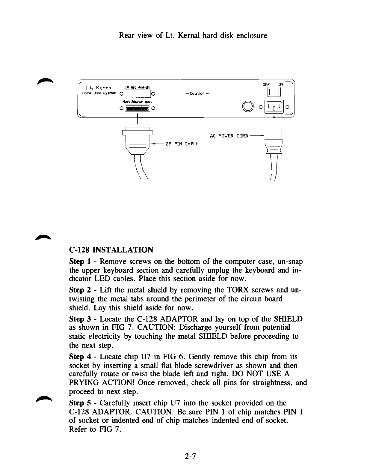
Rear view of Lt. Kernal hard disk enclosure
C-128 INSTALLATION
Step 1 - Remove screws on the bottom of the computer case, un-snap
the upper keyboard section and carefully unplug the keyboard and indicator LED cables. Place this section aside for now.
Step 2 - Lift the metal shield by removing the TORX screws and untwisting the metal tabs around the perimeter of the circuit board
shield. Lay this shield aside for now.
Step 3 - Locate the C-128 ADAPTOR and lay on top of the SHIELD
as shown in FIG 7. CAUTION: Discharge yourself from potential
static electricity by touching the metal SHIELD before proceeding to
the next step.
Step 4 - Locate chip U7 in FIG 6. Gently remove this chip from its
socket by inserting a small flat blade screwdriver as shown and then
carefully rotate or twist the blade left and right. DO NOT USE A
PRYING ACTION! Once removed, check all pins for straightness, and
proceed to next step.
Step 5 - Carefully insert chip U7 into the socket provided on the
C-128 ADAPTOR. CAUTION: Be sure PIN 1 of chip matches PIN 1
of socket or indented end of chip matches indented end of socket.
Refer to FIG 7.
2-7
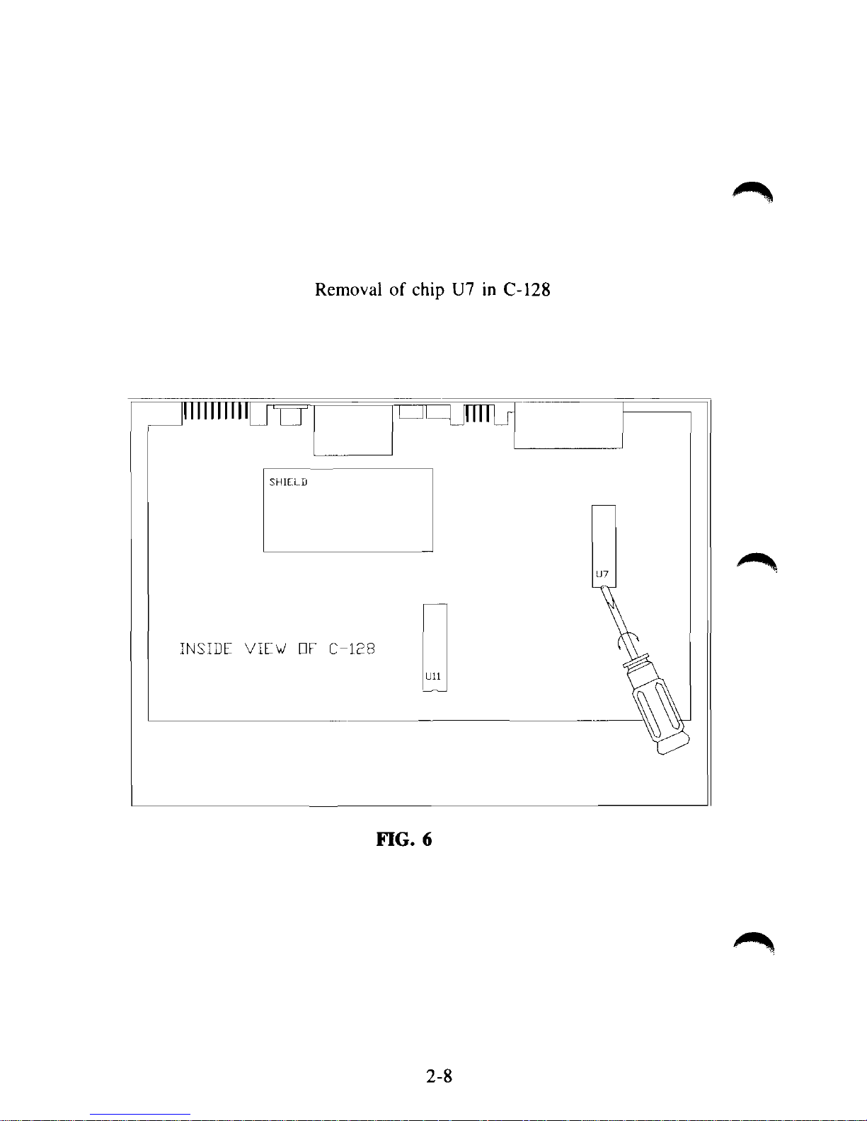
Removal of chip U7 in C-128
On
INSIDE VIEW EiF C-128
FIG. 6
2-8
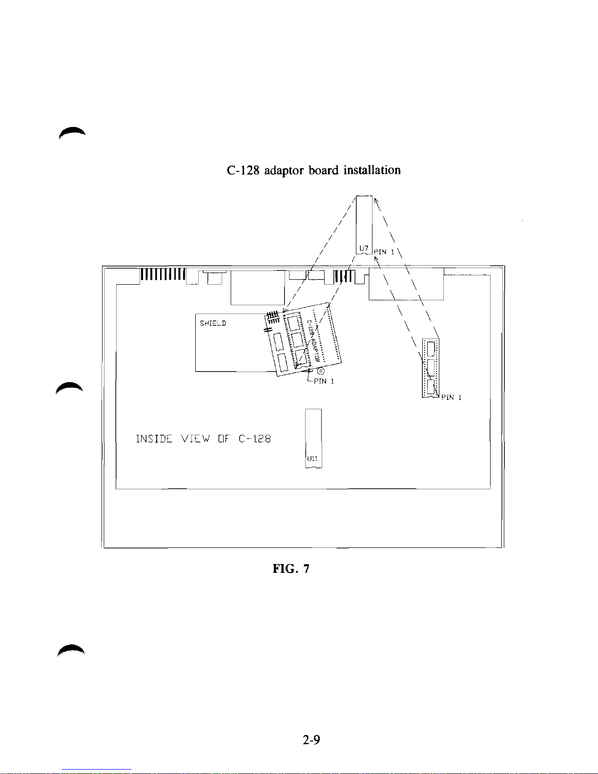
C-128 adaptor board installation
TO
INSIDE VIEW OF C-128
FIG. 7
2-9

C-128 cable connections with Rev C adaptor board
\
\
\
PIN
1
\
4
\
10
INSIDE VIEW DF C-128
FIG 7A
The Rev B and Rev C adaptor boards are functionally identical. They vary
only in size. Your Lt. Kernal 128 system may contain either Rev board.
2-9A
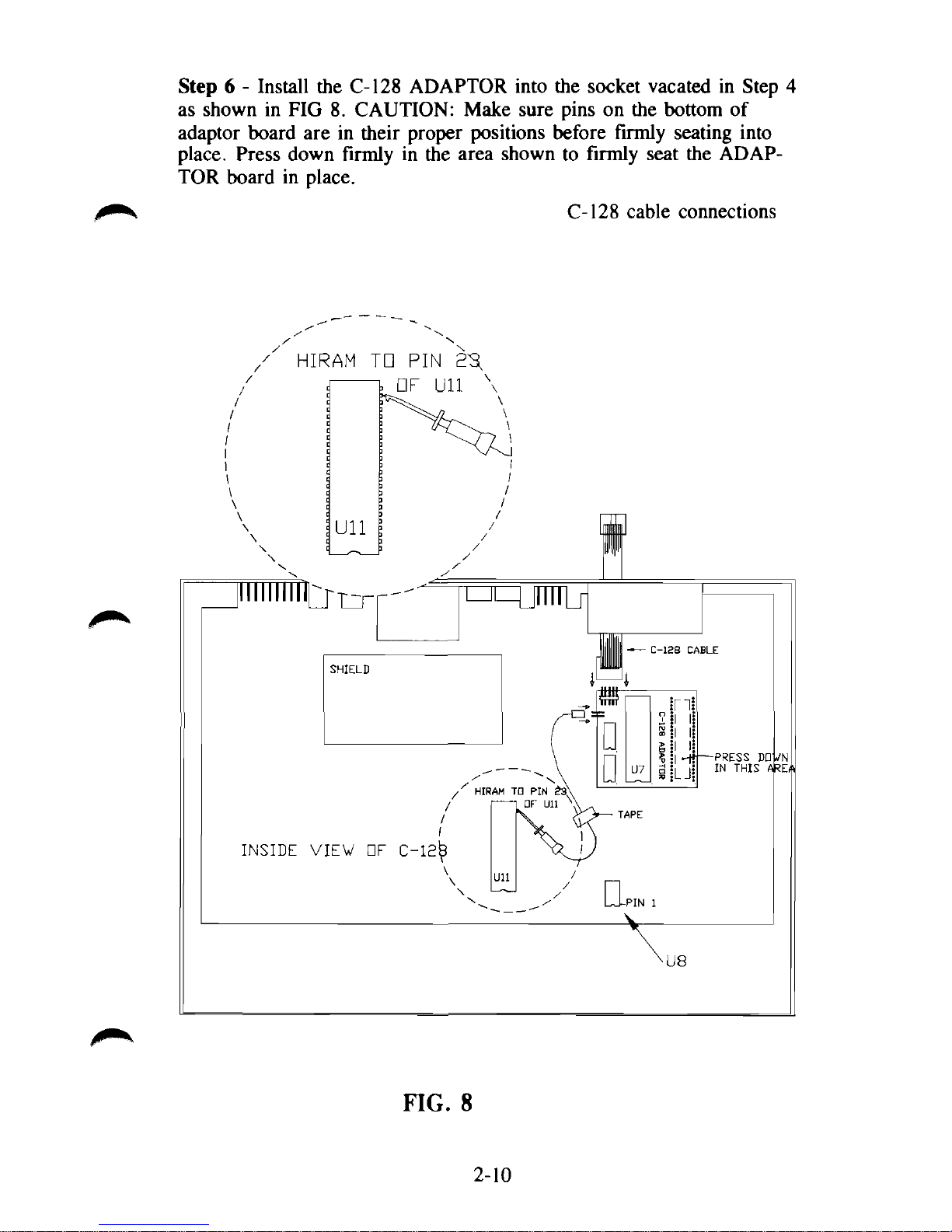
Step 6 - Install the C-128 ADAPTOR into the socket vacated in Step 4
as shown in FIG 8. CAUTION: Make sure pins on the bottom of
adaptor board are in their proper positions before firmly seating into
place. Press down firmly in the area shown to firmly seat the ADAPTOR board in place.
C-128 cable connections
FIG. 8
2-10
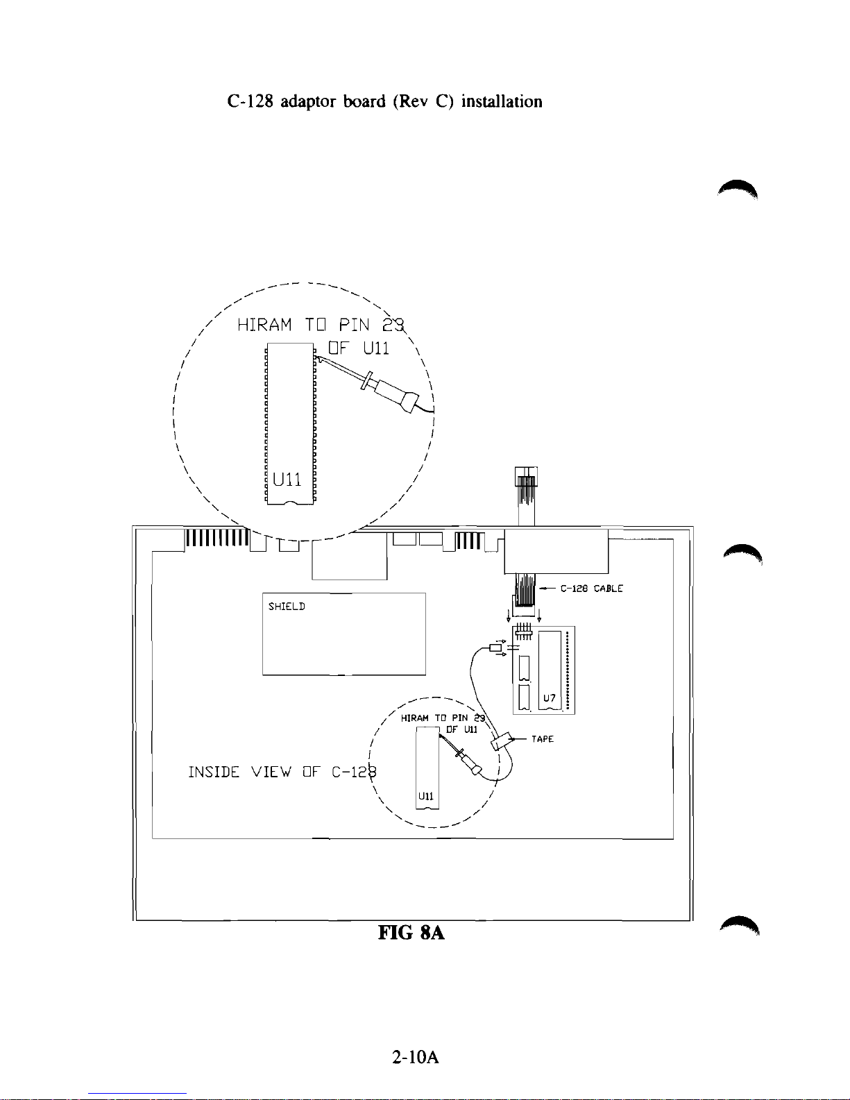
C-128 adaptor board (Rev C) installation
2-10A
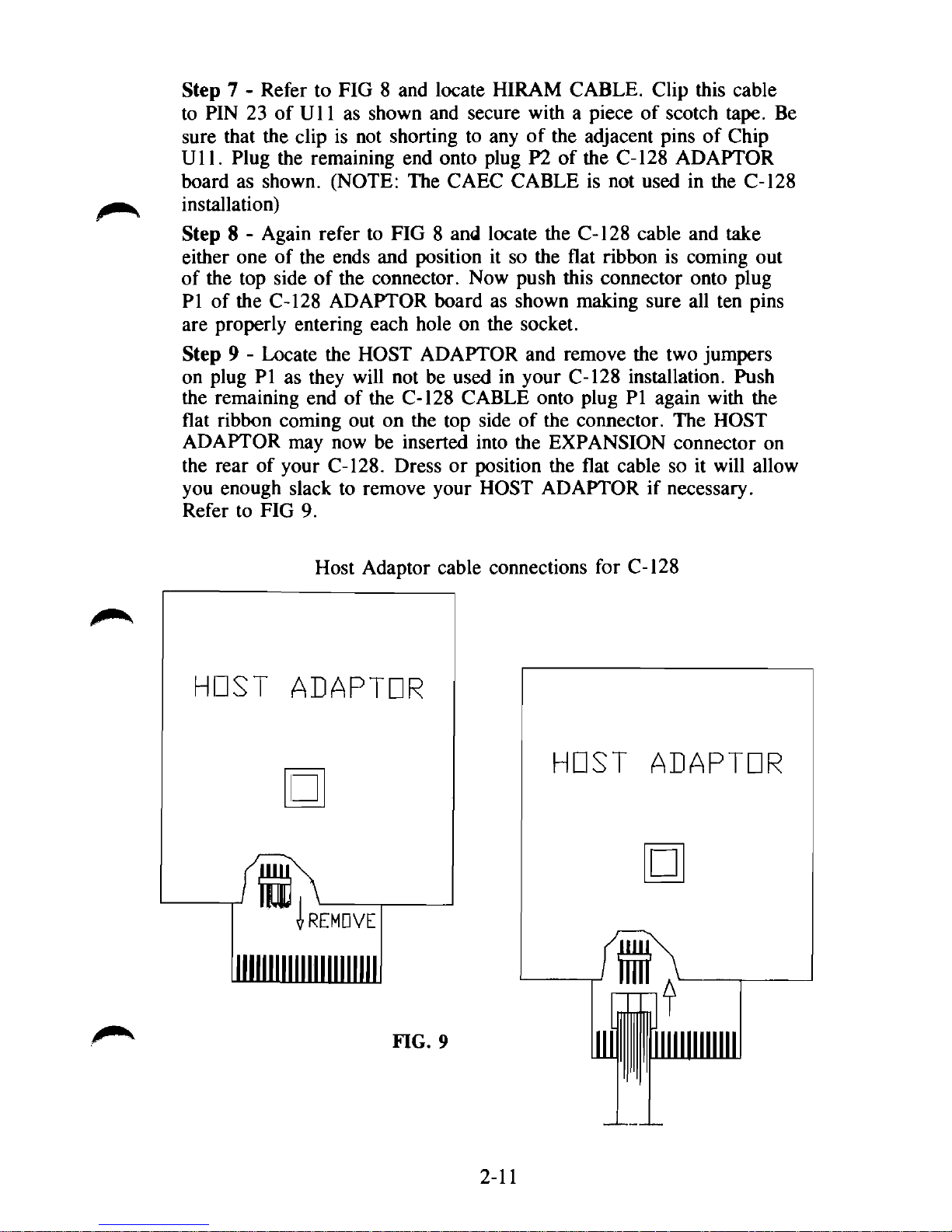
Step 7 - Refer to FIG 8 and locate HIRAM CABLE. Clip this cable
to PIN 23 of U11 as shown and secure with a piece of scotch tape. Be
sure that the clip is not shorting to any of the adjacent pins of Chip
Ull.
Plug the remaining end onto plug P2 of the C-128 ADAPTOR
board as shown. (NOTE: The CAEC CABLE is not used in the C-128
installation)
Step 8 - Again refer to FIG 8 and locate the C-128 cable and take
either one of the ends and position it so the flat ribbon is coming out
of the top side of the connector. Now push this connector onto plug
PI of the C-128 ADAPTOR board as shown making sure all ten pins
are properly entering each hole on the socket.
Step 9 - Locate the HOST ADAPTOR and remove the two jumpers
on plug PI as they will not be used in your C-128 installation. Push
the remaining end of the C-128 CABLE onto plug PI again with the
flat ribbon coming out on the top side of the connector. The HOST
ADAPTOR may now be inserted into the EXPANSION connector on
the rear of your C-128. Dress or position the flat cable so it will allow
you enough slack to remove your HOST ADAPTOR if necessary.
Refer to FIG 9.
HOST
Host Adaptor cable connections for C-128
ADAPTOR
•
rREMDVE
HOST
ADAPTOR
•
FIG. 9
2-11
Step 10 - Replace the metal shield on the C-128 main board being
careful not to pinch or bind the C-128 CABLE.
Step 11 - Install the keyboard sections by re-connecting the cables,
snap case halves together, and install bottom screws in case.
Step 12 - Locate the 25 pin SIGNAL cable, plug one end into the
connector on the rear of the Host Adaptor and secure the cable with
the attached screws. Refer to FIG 4.
Step 13 - Attach remaining end of the 25 PIN SIGNAL cable to the
HOST ADAPTOR INPUT connector of the HARD DISK enclosure.
Again, secure the cable with the attached screws. Refer to FIG 5.
Step 14 - Locate the AC POWER CABLE and plug female end into
the AC POWER receptable of the HARD DISK enclosure. Make sure
the Power Switch is in the OFF position and plug the male end into a
properly grounded 115 volt AC, 60 Hz outlet. Refer to FIG 5.
Step 15 - Re-connect any other components to your system such as
printers, floppy disk and other accessories.
Step 16 - Refer to Power Application Sequence page 2-20.
128D INSTALLATION
Step 1 - Unplug power, keyboard, and all other connections from the 128D
computer.
Step 2 - Remove the 2 screws on the bottom and the 3 screws on the back
of the computer case. Slide top back and lift up to remove. Place this aside
for now.
Step 3 - Locate the 128D Adaptor Board and place it on a firm, flat sur-
face.
CAUTION: Discharge yourself from potential static electricity by
touching the metal case of
the
computer before proceeding to the next step.
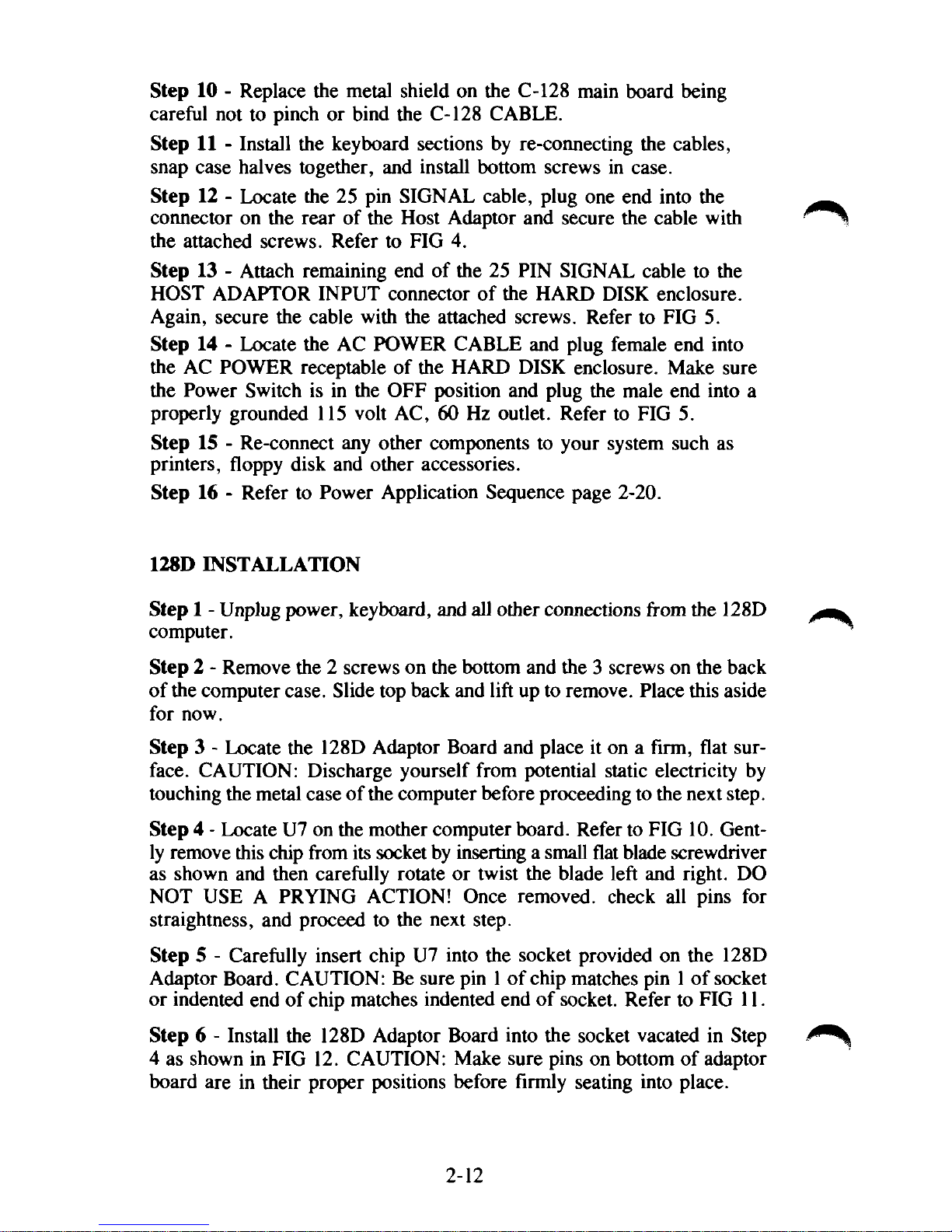
Step 4 - Locate U7 on the mother computer board. Refer to FIG 10. Gently remove this chip from its socket by inserting a small flat blade screwdriver
as shown and then carefully rotate or twist the blade left and right. DO
NOT USE A PRYING ACTION! Once removed, check all pins for
straightness, and proceed to the next step.
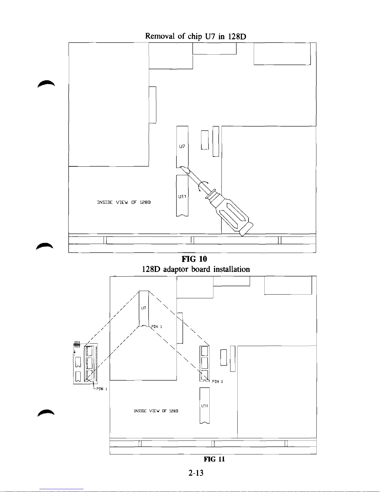
Step 5 - Carefully insert chip U7 into the socket provided on the 128D
Adaptor Board. CAUTION: Be sure pin 1 of chip matches pin 1 of socket
or indented end of chip matches indented end of socket. Refer to FIG 11.
Step 6 - Install the 128D Adaptor Board into the socket vacated in Step
4 as shown in FIG 12. CAUTION: Make sure pins on bottom of adaptor
board are in their proper positions before firmly seating into place.
2-12
INSIDE VIEW OV 128D
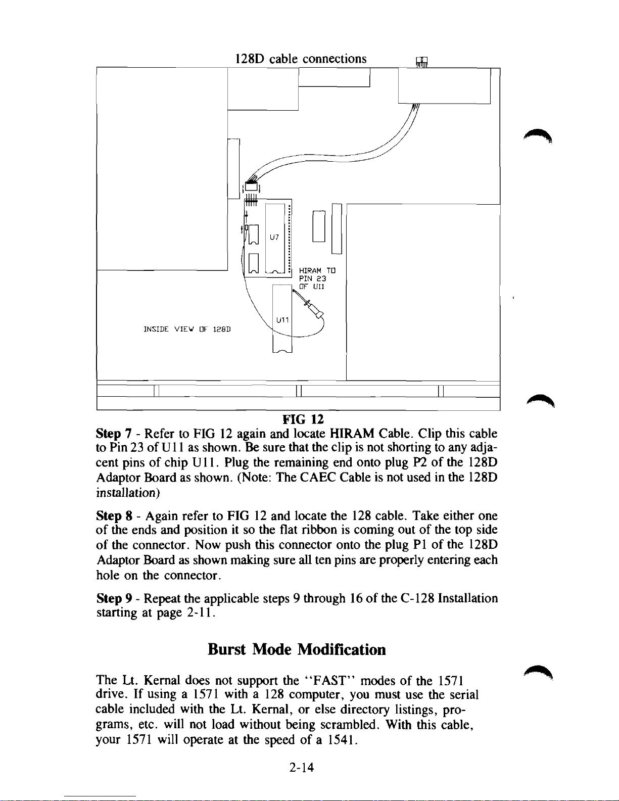
128D cable connections
FIG 12
Step 7 - Refer to FIG 12 again and locate HIRAM Cable. Clip this cable
to Pin 23 of
U11
as shown. Be sure that the clip is not shorting to any adja-
cent pins of chip Ull. Plug the remaining end onto plug P2 of the 128D
Adaptor Board as shown. (Note: The CAEC Cable is not used in the 128D
installation)
Step 8 - Again refer to FIG 12 and locate the 128 cable. Take either one
of the ends and position it so the flat ribbon is coming out of the top side
of the connector. Now push this connector onto the plug PI of the 128D
Adaptor Board as shown making sure all ten pins are properly entering each
hole on the connector.
Step 9 - Repeat the applicable steps 9 through 16 of the C-128 Installation
starting at page 2-11.
Burst Mode Modification
The Lt. Kernal does not support the "FAST" modes of the 1571
drive. If using a 1571 with a 128 computer, you must use the serial
cable included with the Lt. Kernal, or else directory listings, programs, etc. will not load without being scrambled. With this cable,
your 1571 will operate at the speed of a 1541.
2-14
The following steps instruct how to modify your 128 computer to take
advantage of the burst mode. The Burst Mode Modification MUST
BE DONE if you are using a C-128D computer to work correctly
with the Lt. Kernal. If you do not have a need for the burst mode, we
suggest that you do not perform this modification. It will VIOLATE
your Commodore warranty. If you do not have any technical skills and
yet would like to make this modification, we suggest you have a
qualified technician perform it.
Step 1 - Remove screws on the bottom of the computer case, unsnap the
upper keyboard section and carefully unplug the keyboard and indicator
LED cables. Place this section aside for now.
Step 2 - Lift the metal shield by removing the TORX screws and untwisting
the metal tabs around the perimeter of the circuit board shield. Lay this
shield aside for now.
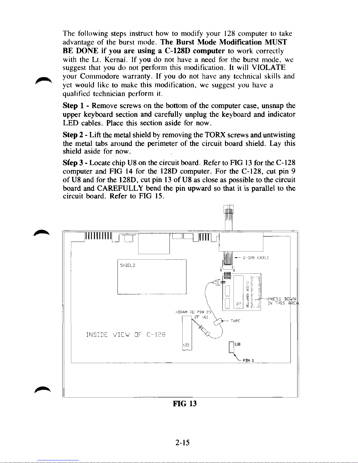
Sfep 3 - Locate chip U8 on the circuit board. Refer to FIG 13 for the C-128
computer and FIG 14 for the 128D computer. For the C-128, cut pin 9
of U8 and for the 128D, cut pin 13 of
U8
as close as possible to the circuit
board and CAREFULLY bend the pin upward so that it is parallel to the
circuit board. Refer to FIG 15.
Illlllllll
INSIDE VIEW
ElF C-128
HIRAM
ID PIN 2
• F Ull
FIG 13
mi
I
"
4JJJJ
TTTTT
n
u
D
- C-128
117
?
a
CABLE
n|
-PRESS
IN
THIS
DO
A
2-15
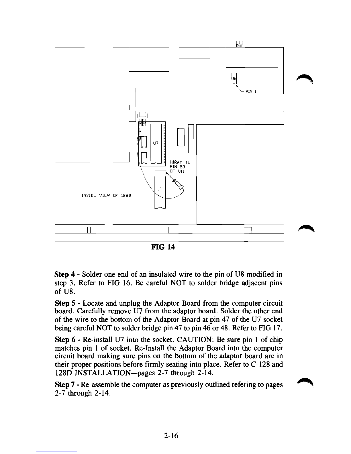
FIG 14
Step 4 - Solder one end of an insulated wire to the pin of U8 modified in
step 3. Refer to FIG 16. Be careful NOT to solder bridge adjacent pins
of U8.
Step 5 - Locate and unplug the Adaptor Board from the computer circuit
board. Carefully remove U7 from the adaptor board. Solder the other end
of the wire to the bottom of the Adaptor Board at pin 47 of the U7 socket
being careful NOT to solder bridge pin 47 to pin 46 or
48.
Refer to FIG 17.
Step 6 - Re-install U7 into the socket. CAUTION: Be sure pin 1 of chip
matches pin 1 of socket. Re-Install the Adaptor Board into the computer
circuit board making sure pins on the bottom of the adaptor board are in
their proper positions before firmly seating into place. Refer to C-128 and
128D INSTALLATION—pages 2-7 through 2-14.
Step 7 - Re-assemble the computer as previously outlined refering to pages
2-7 through 2-14.
2-16

2-17

I/O Modification for CP/M
CP/M operation requires the Host Adaptor to be set for I/O-l. The
current version of the Lt. Kernal should already be set for I/O-l.
Refer to FIG 18. The current version Host Adaptor (Rev. C) is the
only one that has the I/O selectable pins. If you have an older version
system, you will have to do a slight modification to the Host Adaptor.
Refer to FIGs 19 and 20.
!/•
Illlllllllllllllllllll
FIG 18
Host Adaptor Rev. C
To select I/O-l, remove the jumper from 1/0-2 pins and slide on I/O-l
pins.
The Rev. B Host Adaptor is manufactured to operate in I/0-2 mode.
To convert to I/O-l follow the steps below. If you do not have
technical skills, we suggest you have a qualified person perform this
modification.
Step 1 - Cut trace on component side of Host Adaptor as shown that
connects gold pad 10 with feed through hole.
Step 2 - Solder an insulated wire (approx. 22 ga.) as shown from feed
through hole to gold pad 7. Be careful not to solder 'bridge' the wire
to any other surrounding pads.
2-18

CUT TRACE HERE
^-PIN 10
FIG 19
Host Adaptor Rev. B
SOLDER WIRE HERE
iiiiiiiiiiiiiiii
FIG 20
Host Adaptor Rev. B
2-19

POWER APPLICATION SEQUENCE
Power should be applied to your Lt. Kernal/Commodore combination
in a specific manner.
Before you do power up your system, please remember that things are
going to act a little differently than what you accustomed to seeing, so
read this whole section before actually applying power. We want you
to know what to expect BEFORE it happens.
Follow the steps in this order:
1.
Monitor or television set.
2.
Printers, floppy disks, and any other accessories EXCEPT the
Lt. Kernel hard-disk.
3.
The Lt. Kernal hard disk system.
4.
Finally, the Commodore computer
itself.
POWER REMOVAL SEQUENCE
1.
The Lt. Kernal hard disk system
2.
Printers, floppy disks, and any other still powered accessories,
including your monitor or TV set.
3.
The computer.
Read Section IX before continuing.
A demo program called PXE is located on LUO, USEROO, and may be
run in the C-64 mode by simply typing PXE and then press the
"RETURN" key. Ignore the message "HIT ANY KEY WITHIN 5
SECONDS" or it will take you to an un-documented editor of the
demo program. ENJOY!
2-20

III.
ACTIVATING THE SYSTEM
The Lt. Kernal is configured to come up in the 64 mode. (This can be
changed). Therefore, your computer system must be ready to use the
64 mode which is a 40 column screen.
With the 128 computer, DO NOT HOLD the C= key down during
power up. The Lt. Kernal will automatically take control and place
the 128 in a 64 mode. If you do not see any results at this point, you
are probably in an 80 column condition.
NOW IT ALL COMES TOGETHER! When you apply power to
your system without the Lt. Kernal present, you ordinarily would ex-
pect to see the Commodore BASIC power-up messages and then the
BASIC ready prompt within just a couple of seconds of turn-on.
That's not going to happen with the Lt. Kernal ... at least not instant-
ly. What will happen instead is this:
As soon as the drive has run up to speed, you should see the indicator
light on the front of the drive blink twice, just briefly. About three
seconds after that, the light will come on solidly for one second while
the Lt. Kernal copyright messages appear. If the volumn control on
your monitor is turned up, you will hear a beep and see a new ready
prompt with the following information:
C64 D#08 LU10 USER00 PORT#00 READY
These prompts will be explained in latter parts of the manual. On a
C-128, you may see even more activity. If the Lt. Kernal is configured to power-up as a C-64, you will see the screen blank again.
The whole process repeats, finally to arrive at the C-64 mode of
operation.
A lot went on to get to this point, and that's why there's a delay after
you turn on the system. While you were waiting for the system signon message, and while the disk drive was running up to speed, a long
series of system diagnostics took place — checking the Lt. Kernal
Host Adaptor — testing the drive's controller electronics — and finally, even testing the Disk Operating System software installed on your
drive.
3-1

If any one of the diagnostics along the way should fail, you'll just see
the regular Commodore sign-on without the Lt. Kernal message, and
without the beep. If the tests do fail, please TURN THE SYSTEM
OFF and turn directly to "TROUBLE-SHOOTING" in this manual.
NOW CHECK YOUR CABLING AND WIRING - AND
TURN ON YOUR SYSTEM.
Then we'll introduce you to your new DOS.
Running the INSTALLCHECK program
The Lt. Kernal DOS features a test program called INSTALLCHECK
that tests the circuitry of the Host Adaptor and detects any errors of
the HIRAM and CAEC connections you made to your computer.
To use the INSTALLCHECK program, you must first be in the 64
mode and then simply type INSTALLCHECK. The program will begin
its testing and prompt you through the process. If any of the tests
should fail, recheck your connections.
3-2

IV.
OPERATING CONCEPTS
HOW IT WORKS
The Lt. Kernal DOS was written with the business user in mind.
Many comfortable and easy-to-use new features have been added to
your Commodore disk operating system while still supporting most of
the existing 1541 floppy commands. The only commands not supported
have no appropriate use in this environment. Most existing applications
written in BASIC will run unmodified under the Lt. Kernal DOS.
Many machine language applications and utilities such as assemblers,
editors, and 'wedges' will also operate normally under the Lt. Kernal's
control — but some programs will not run in cooperation with the Lt.
Kernal. The reason lies in how the Lt. Kernal got its name, and in
how it operates.
In order to support the tremendous speed at which the Lt. Kernal
operates, it was essential that the cartridge/expansion port be used to
communicate with the hard disk. To do that, there has to be a body of
programs run by the Commodore computer to control the cartridge
port and the Lt. Kernal Host Adaptor
Kernal to operate without making you sacrifice any of the memory you
were accustomed to using. That has been accomplished by making the
DOS support programs run in RAM (a modified Kernal) on the Lt.
Kernal Host Adaptor. Since the Commodore computer itself is running
the DOS, a few "programming considerations" (discussed in a later
section) must be observed in order not to disrupt the always-running
DOS.
itself.
But we wanted the Lt.
4-1

This page intentionally left blank
4-2

V.
COMMANDS OVERVIEW and
DOS FEATURES (review)
RUN MODE Features or Enhanced Commands
autoaccess LDLU
autostart LG
bell LOAD
BUILDKEY fde OPEN
COPY SAVE
DELETE key SCRATCH
INSERT key SEARCH key
SHUFFLE
DIRECT MODE Features or Enhanced Commands
TT
ACTIVATE
AUTOCOPY
AUTODEL
AUTOMOVE
BUILD
BUILDCPM
BUILDINDEX
CHANGE
CHECKSUM
CLEAR
CONFIG
COPY
D
DEL
DI
DIR
DUMP
ERA
EXEC
FASTCOPY
FETCH
FIND
G064
G0128
GOCPM
ICQUB
invoke
L
LOAD
LKOFF
LKREV
LU
MERGE
OOPS
QUERY
RECOVER
RENUM
S
SHIP
TYPE
UPDATEDOS
USER
VALIDATE
5-1

This page intentionally left blank
5-2

VI.
COMMAND SYNTAX DEFINITIONS
Throughout the descriptions of the commands which follow, we will
use certain conventions to describe the command syntaxes and
responses. Here are the definitions of those conventions.
• COMMANDS are always noted in UPPER-CASE. You enter
commands from the keyboard, or include them in programs.
• FEATURES are noted in LOWER-CASE. A feature is an enhanced
or added mode of operation, not a command.
• Within a command's syntax description, capital letters indicate the
COMMAND name as you must enter it.
• Within a command's syntax description, lower-case letters indicate
FILE-names or parameters for the command.
• A " " symbol indicates_a__REQUIRED space in the
command syntax.
• Text within brackets indicates [optional parameters or file names].
• A "—" symbol indicates—a—REQUIRED—hyphen—in—the—
command—syntax.
• A term "< range >" indicates a save range for the SAVE command
where the range may be expressed either in decimal or hexidecimal
as
hexadecimal range <$hex start-hex end> inclusive
decimal range <dec. start-dec. end> inclusive
• An exclamation mark (!) appended to the end of a DIRectory listing
line indicates that the file has been changed or modified since the
last CLEAR or FASTCOPY was executed.
• lfn is the Commodore 'logical file number' convention
• dev refers to the hardware device number of the drive selected
• sa is the Commodore 'secondary address or channel number'
• lu refers to the logical drive number (not to be confused with
_ hardware device number) which may accompany a LOAD, SAVE,
or OPEN command.
6-1

• When used in the context of LUs or Logical Drives, a DIRECTORY
is a list of the fdes stored on that LU.
• user refers to a logical sub-directory number within a logical drive's
(LU's) directory.
• When used in the context of KEY fdes, a DIRECTORY is one of up jm*.
to five LISTS of KEYS stored in a KEY file.
• A KEY is a fixed length string stored in a KEY file which is
associated with a RECORD NUMBER for use in indexing records
within RELative files.
6-2

VII.
RUN-Mode Features and Commands
autoaccess
feature
Autoaccess allows transfer of a load request to the floppy disk when a
file-not-found condition arises on the hard disk.
If the hard disk is defined as device #8 (this is user definable), and the
floppy is also defined as device #8, then all Commodore syntax
LOAD's will first be referred to the hard disk. If the file is not found,
than an attempt to LOAD that same file from the floppy will be made.
This feature may be disabled via CONFIG if it interferes with your
application software.
7-1

autostart
feature
Mode: Power-up or hardware reset
Autostart is almost self-explanatory. Simply stated, any program saved
under the name "AUTOSTART" will be automatically loaded and run
upon power-up or after a hardware reset. Autostart functions for both
BASIC and machine language programs, and is one of the best
features any turn-key business system can have available.
Autostart may be overridden by holding down the space bar during a
power-up or reset start.
7-2

bell
feature
Mode: Direct or Run
Bell offers programmers a method of issuing an audible prompt
without having to maintain SID drivers in their programs. Any PRINT
from BASIC or CHROUT from machine language of the ASCII Bell
character [CHR$(7) or hex, 07] will cause a beep on the monitor or
television set if the BEEPER option is selected by the user in the
CONFIG mode described later.
7-3

BUILDKEY file
command
From BASIC
Syntax: SYS 64628:0,lfn,directory,Stringvar,reel,rech,status
Ifn is not used, but a dummy variable must be provided
directory is the NUMBER OF DIRECTORIES you wish to have built
in the new KEY file
Stingvar contains the KEY FILE NAME and the KEY LENGTHS for
each directory you wish to create
reel and rech are the low and high order bytes of the number of keys
in the largest directory.
status is the value returned from the SYS indicating the success or
failure of the BUILDKEY operation
Please see the KEY file usage examples in Section IX of this manual
for detailed examples of BUILDKEY.
For further descriptions of KEY file operations, refer to Section IX,
page 9-16 for information on machine language calls.
7-4

DELETE key
command
From BASIC
Syntax: SYS 64628:2,lfn,directory,Stringvar,reel,rech,status
Ifn is the logical file number of a KEY file already OPENed on the
hard drive.
directory is the number (1-5) of the selected key DIRECTORY within
the KEY file.
Stringvar contains the EXACT key you wish to delete,
reel and rech are the Low and High bytes of the EXACT double-
precision record number associated with the key to be deleted,
status is the value returned from the SYS to indicate the success or
failure of the DELETE to occur.
Please see the KEY files usage examples in Section IX of this manual
for detailed examples of DELETE key.
For further descriptions of KEY file operations, refer to Section IX,
page 9-16 for information on machine language calls.
7-5

INSERT key
command
From BASIC
Syntax: SYS 64628:l,lfn,directory,Stringvar,reel,rech,status
lfn is the logical file number of a KEY file already OPENed on the
hard drive.
directory is the number (1-5) of the selected key DIRECTORY within
the KEY file.
Stringvar contains the EXACT key you wish to insert,
reel and rech are the Low and High bytes of the EXACT double-
precision record number to be associated with the key being inserted,
status is a value returned from the SYS to indicate the success or
failure of the INSERT to occur.
For further descriptions of KEY file operations, refer to Section IX,
page 9-16 for information on machine language calls.

LDLU
command
Syntax: OPEN #lfn,dev,sa,''Ldev#LU#USR#"
Mode: Direct or RUN via channel 15
dev# is a single hexidecimal digit expressing the NEW Lt. Kernal
device number.
LU# is a single HEXIDECIMAL digit expressing the NEW Lt. Kernal
operating LU.
USR# is a single HEXIDECIMAL digit expressing the NEW Lt. Kernal operating USER partition.
LDLU permits you to change the operating characteristics of the Lt.
Kernal on the fly. Any values provided which are illegal will be ignored. There is NO error status returned from the LDLU command
except SYNTAX ERROR. A syntax error will be returned if ANY of
the values are illegal, or not provided. BUT THE VALUES WHICH
WERE LEGAL, will be acted upon, even if a syntax error exists.
Example:
To change the operation of the Lt. Kernal from
Device #8
LU 0
USER 2
to
Device #9
LU 10
USER 15 issue
OPEN 15,8,15,"L9AF":CLOSE15
Always remember that if you change the operating DEVICE number
of the Lt. Kernal , all files OPENed under the OLD device will still
remain OPEN, but now under the NEW number.
The LDLU command will permit you to open files across LU and
USER boundaries then to switch back to your 'normal' operating LU,
keeping those files open.
There is no DEFAULT setting for LDLU.
7-7

LG
command
Syntax: Open 15,8,15, "LG" or
Open 15,8,15, "LG#"
LG# is a single HEXIDECIMAL digit representing the LU# for which '
LG is to be performed.
LG 'gets' the current STATUS of the currently-logged or expressly-
requested LU.
The status of the LU is refunded via the command/error channel in an
error message format. The status is read via the following syntax:
Input#15,E,E$,D,L,U,BF,BU
where E =6 (command successful) or
other than 6 (command not successful)
E$ = "STATUS"
D = current device#
L = current or requested LU#
U = current user #
BF = current BLOCKS FREE (hard drive blocks)
BU = current BLOCKS USED (hard drive blocks)
LG will return this status in one second or less, regardless of the size
or fulness of the LU. Approximate CBM blocks are computed as INT
(Hardblocks/254*512)
7-8

Syntax: LOAD "[|u:]|user:]filename",dev[,sa]
dev is the drive selected
i^^>
sa is the secondary address where
0 or none = BASIC load
and 1 = machine-language load
Mode: Direct or Run
on the hard drive, LOAD may be abbreviated to
L_["][lu:][user:]filename["]
with optional quotation marks about the name and without specifying
either device number or secondary address.
when used in this abbreviated syntax, LOAD will load the file at its
correct load address depending on the filetype.
Example: L l.MYFILE - LOADs the program MYFILE from the hard
disk logical unit #1.
LOAD
command
7-9

OPEN
command
Syntax: OPEN lfn,dev,sa,"[lu:]filename"
Ifn is the logical file number
dev is the physical address (number) of the disk accessed
sa is the DOS channel associated with this logical file (channel 15 is
reserved for the command/error channel).
Mode: Direct or Run
OPEN retains exactly the same syntax as when used with the 1541
floppy disk, but now allows up to SEVEN logical FILES regardless of
type,
to be OPEN for reading and writing simultaneously on the hard
disk. The Commodore ROM operating system will allow you to have
as many as three more files open on a floppy disk, as well, for a total
of ten open files.
Some 1541 file types occupy more than one channel when OPENed.
All Lt. Kernal files use only one channel. This enhancement does
NOT increase the open channel capability of the 1541 floppy disk.
Note that the "user" number is NOT an option in OPEN.
7-10

SAVE
command
Syntax: SAVE "[<range>][lu:]filename",dev
where dev is the disk selected onto which to save the file
Mode: Direct or Run
SAVE may be abbreviated on the hard disk (only in the Direct Mode)
to
S_["][
< range > ]|lu:]filename['']
without optional quotation marks about the filename and range, and
without specifying the disk's device number.
Where < range> is specified, the range may be stated either in hexadecimal or decimal and is an INCLUSIVE range.
Examples:
S <$2000-3FFF>MYFILE - saves the area of memory from Hex
2000 through and including Hex 3FFF to the hard disk.
SAVE "< 1024-4096 >MYFILE", 8 - Saves the area of memory
from decimal address 1024 through and including location 4096 to
drive #8.
Note that USER# is NOT presently a SAVE operation.
7-11

SCRATCH
command
Syntax: OPEN lfn,dev,sa,"S[lu][user:]:filename"
Mode: Direct or Run via channel 15
The SCRATCH command is available in the Run mode only via the
command/error channel.
Note that the colon following the LU number is NOT optional.
In the Direct mode, the ERA command discussed later in this manual
performs the SCRATCH function.
SCRATCH deletes the NEXT file encountered on the hard disk which
qualifies according to the filename. This mode differs from the 1541
floppy disk equivalent in that the 1541 SCRATCH command deletes
ALL filenames qualifying according to the filename given.
This limitation may be overridden via CONFIG for applications which
require pattern-match scratching capabilities.
7-12

SEARCH key
command
From BASIC
Syntax: match search SYS
64628:3,lfn,directory,Stringvar,recl,rech,status
greater-than search
SYS 64628:4,lfn,directory,Stringvar,recl,rech,status
less-than search
SYS 64628:5,lfn,directory,Stringvar,reel,rech,status
lfn is the logical file number of a KEY file already OPENed on the
hard drive.
directory is the number (1-5) of the selected key DIRECTORY within
the KEY file.
Stringvar contains the key for which you wish to search.
On return from the SYS
reel and rech will contain the double-precision record number
associated with the first key to satisfy the SEARCH criteria,
status will contain a value to indicate the success or failure of the
SEARCH.
Please see the KEY files usage examples in Section DC of this manual
for detailed examples of SEARCH key.
For further descriptions of KEY file operations, refer to Section IX,
page 9-16 for information on machine language calls.
7-13

SHUFFLE key directory
command
From BASIC
Syntax: SYS 64628:7,lfn,directory,Stringvar,reel,rech,status
lfn is the logical file number of a KEY file already OPENed on the
hard drive.
directory is the number (1-5) of the selected key DIRECTORY you
wish to SHUFFLE.
On return from the SYS
status will contain a value to indicate the success or failure of the
SHUFFLE.
Please see the KEY files usage examples in Section IX of this manual
for detailed examples of SHUFFLE.
For further descriptions of KEY file operations, refer to Section IX,
page 9-16 for information on machine language calls.
7-14

VIII.
DIRECT-MODE FEATURES and COMMANDS
tt
command
Syntax:
The
CPU mode under which you are presently operating.
This is provided as a quick and easy way to return to your 'home'
LU/User and colors when you have moved elsewhere on the system,
or when a 'break' has changed your screen colors.
TT
TT
command restores all your CONFIG'd DEFAULTS for the
8-1

ACTIVATE
command
Syntax: ACTIVATE
ACTIVATE totally erases an existing logical unit and creates a new
'BAM' and 'INDEX'. ACTIVATE also gives you the opportunity to
create a DOS IMAGE FILE to enhance operating speed on LU's
physically distant from the DOS LU (lu 10).
DO NOT USE THIS COMMAND UNTIL YOU HAVE
THOROUGHLY READ AND COMPLETELY UNDERSTAND THE
ACTIVATE and CONFIG PROCESSES.
ACTIVATE must be run ONLY AFTER the LU 'type' has been
assigned via CONFIG.
ACTIVATE and CONFIG are discussed in detail in the 'PROGRAMMING CONSIDERATIONS' chapter (section IX) of this manual.
8-2

AUTOCOPY
command
Syntax: AUTOCOPY
This self-documenting command allows you to rapidly copy multiple
fdes across LU and USER boundaries.
8-3

AUTODEL
command
Syntax: AUTODEL
AUTODEL is self-documenting, and allows you to rapidly delete
multiple fdes from a specified lu/user area. If you wish to delete ALL
files from an existing LU, ACTIVATE is faster.
8-4

AUTOMOVE
command
Syntax: AUTOMOVE
AUTOMOVE is a self-documenting command which allows you to
rapidly MOVE files from one USER sub-directory of an LU to
another USER sub-directory of the same LU.
8-5

BUILD
command
Syntax: BUILD filename,nrecs,reel
filename is any legal 1541 filename
nrecs indicates the number of records to be formatted (65535 max)
reel indicates the length in bytes of each record (3072. max)
The maximum allowable size of any one file on the Lt. Kernal system
is 32768 hard disk blocks of 512 bytes, or 16.78 mega-bytes.
BUILD is similar to the 1541 RELative-file formatting function in that
it creates a relative file 'formatted' with a number of fixed length
records. Unlike the 1541 which requires that you OPEN and POSITION within a relative file to format it, BUILD is a direct mode command, and is EXTREMELY FAST.
The Lt. Kernal will also format a relative file using the 1541 OPEN
and POSITION syntaxes, but more slowly than when using BUILD.
8-6

BUILDCPM
command
Syntax: BUILDCPM
BUILDCPM sets up necessary machine status to construct a CP/M
operating system on the CP/M DEFAULT LU you have previously
defined via CONFIG.
You must have previously defined a CP/M default LU, and MUST
have ACTIVATEd it prior to invoking BUILDCPM.
You must be in the 128 mode to invoke BUILDCPM.Please refer to
Section 'Using CP/M on the Lt. Kernal' prior to using this
command.
Refer to Section XIII, page 13-1 for the installation of CP/M on the
Lt. Kernal.
8-7

BUILDINDEX
command
Syntax: BUILDINDEX
BUILDINDEX builds a KEY fde with up to five DIRECTORIES of
keys.
Necessary information about the file will be requested by
BUILDINDEX as required.
You will first be requested to supply the name of the new KEY file to
be built.
You will then be requested to specify how many DIRECTORIES (lists
of keys) the file will hold. Once a KEY file is built, the number of
directories within it may not be changed. You must build at least one
directory, and you are limited to five within any one KEY file.
You will be requested to supply the KEY LENGTH for each direc-
tory. This specifies the permanently fixed length of the key strings
contained within each of the directories. Each directory's key length
may be different and may range from 1 to 30 characters.
Once you have supplied the key length for the last directory specified,
BUILDINDEX will create the KEY file.
Please see the KEY file usage examples in Section IX of this manual
for detailed examples BUILDINDEX.

CHANGE
command
Syntax: CHANGE [lu:][user:]filename
CHANGE allows you to change several characteristics of a file. You
may CHANGE the:
Filename
User number
Load address
'Dirty flag' (archiving bit)
M/L or BASIC program types
8-9

CHECKSUM
command
Syntax: CHECKSUM
CHECKSUM totally checks the intergrity of the DOS on LU 10 and
forces an UPDATEDOS of all LU's on which Lt. Kernal DOS image
files exist.
8-10

CLEAR
command
Syntax: CLEAR
CLEAR permits you to clear the 'dirty-flags' of all files in a specified
LU/USER area. CLEAR will request the LU and USER parameters
from you at the appropriate time. To clear the dirty-flag for a single
file,
use the CHANGE command.
Dirty-flags (archiving bits) are the mechanism the Lt. Kernal uses to
do archival backups to floppy disk. Whenever a file is either created
or modified, the Lt. Kernal sets a 'flag' bit in that file's directory entry saying that the file has been modified. Only performing a backup
copy of the file via FASTCOPY, or executing the CLEAR command
will erase that bit. Files with the archiving bit set may be selectively
listed with DIR by using the C option.
8-11

CONFIG
command
Syntax: CONFIG
CONFIG allows the user to establish custom system characteristics for
the Lt. Kernal.
System characteristics affected are
CONFIG menu colors
Logical Drive sizes
Logical Drive 'types' (regular or
CP/M)
C-64 Screen color
C-64 Border color
C-64 Character color
128 40 column Screen color
128 40 column Character color
128 40 column Border color
128 80 column Screen color
128 80 column Character color
Default device #
Default USER partition
Beep enable
Printer Codes
Autoaccess enable
Scratch override
CPU reset mode (C-64, 128, or
CP/M)
CPU speed in 128 mode
C-64 mode KEYPAD enable on
128
Interrupt Traps
Multi-user index locking
CP/M Default LU
Default LU #
In addition to all these things, in a multi-user system, the 'master' user
may configure these items for EACH of up to 16 separate CPU's connected to the system. CPU's OTHER than the 'master' may only
change their OWN CONFIG parameters.
The following is a list of the default parameters:
LU#
Beg. Cyl
DOS
0
1
2
# of Cyl
0000
0030
30
200
0230 200
0430
166
8-12

COPY
command
Syntax: COPY ["] [lu: ] [user: ] [newfilename] = [lu: ] [user: ]oldfilename['']
Mode: Direct or Run
COPY creates a new file copied from oldfilename into newfilename.
Copy will copy fdes across logical unit (logical drive) boundaries to
the currently active subdirectory (user #).
The syntax in RUN mode is:
OPEN lfn,dev, 15,''C[|u]:destfile = [|u:]sourcefile''
Note that almost all the COPY parameters are optional. Several syntaxes will accomplish a COPY of a file.
1.
COPY THISFILE = THATFILE
will copy the file named THATFILE into a new file called
THISFILE on the logical drive on which you are currently
working.
Now assume that you are 'logged' (working) on LOGICAL DRIVE #1
and working in User sub-directory 12 (1:12:).
2.
COPY
2:
THISFILE=THATFILE
will copy the file named THATFILE from logical drive 1 into a
new file called THISFILE on logical drive #2, User #12 (2:12:).
3.
COPY 2: = THATFILE
will copy the file named THATFILE from logical drive 1 into a
new file of the SAME name on logical drive #2, subdirectory 12.
4.
COPY 2:10:=3:5:THATFILE
will demonstrate the ability to copy from and to logical drives on
which you are NOT logged. The syntax above will copy
THATFILE from logical drive #3 subdirectory #5 to logical drive
#2,
subdirectory #10 even though you are currently working on
logical drive #1, user 12.
5.
COPY =3:THATFILE
will copy THATFILE from logical drive #3 to your currently
logged logical unit (2) and currently working subdirectory (12).
The optional quotation marks in the syntax definition for COPY are
allowed so that graphics characters may be included in the filenames.
8-13

D
command
Syntax: D[ drvnum]
drvnum is the desired hardware device number of the hard disk
D is used to temporarily change the device number of the hard disk
from the CONFIGured default. D typed without a drive number will
cause the device number to revert to the power-on default.
8-14

DEL
command
Syntax: DEL line number or
DEL [beg. line] -[end. line]
DEL deletes BASIC program lines in memory. When the hyphen is
used to indicate a range-delete, at least one line number must be
given, (either beginning or end) to satisfy the range calculation.
8-15

DI
command
Syntax: DI
DI (display index) is a self-documenting command. DI displays all of
the active keys in the directories of a KEY file.
Please see the examples of KEY file usage in section IX of this
manual for detailed use of DI.
FILE TYPE DEFINITIONS
The Lt. Kernal DOS supports the Commodore conventions for file
type,
such as "SEQ", "REL", etc., but uses within its own operations a more finely divided set of file definitions. Each Lt. Kernal file
type is assigned a numeric type. The types are:
TYPE DEFINITIONS
1 CONTIGUOUS DOS system file
(i.e.
INDEX and DISCBITMAP)
2 CONTIGUOUS DOS system processor
(i.e.
DIR)
3 RANDOM DOS external system
processor (i.e. RENUM)
4 KEY file for indexed RELative files
(supports 5 key directories)
5-10 UNASSIGNED
11 BASIC language program file
stored block-list random
12 MACHINE LANGUAGE program file
stored block-list random
13 SEQUENTIAL FILE (i.e. editor text)
stored block-list random
14 USER FILE
15 RELATIVE FILE
8-16

DIR
command
Syntax: DIR_[[lu:[user:]]:[Tfiltyp][P][S][A][G]|C]_][filename]
DIR is a powerful directory command that allows a directory of the
* hard disk to be listed or optionally printed. Listings based on file type
or file name matches with wild-cards and don't-care characters are
supported. You may use either trailing OR leading wildcards in the
filename specification. The options are:
lu requests the logical drive # from which the DIRectory will be read
user requests the subdirectory on the requested lu.
Tfiltyp (type) filtyp is the numeric hard disk file type.
P (print) causes the listing to be printed
S (sort) causes the listing to be alphabetized
A (all users) lists from all subdirectories on the requested LU
G (global) lists from all subdirectories of ALL LU's
C (changed) lists only those files Changed or Created since the last
backup or CLEAR command was issued. The directory listing for any
file which reflects a 'changed' status will have an exclamation mark (!)
appended to the end.
The options may be used singly or combined in any order except that
the ':options' field must precede the file name specification, and that
the G and A options override the optional user #, and G automatically
implies the A option.
Examples:
DIR - causes a screen listing of all hard disk files in the current
LU/USER area in which you are operating.
DIR :P - causes a printed directory of all hard disk files in the current
subdirectory and LU.
DIR 1:4: MYFI - causes a directory of all files on LU 1 under subdirectory #4 whose names begin with the sequence 'MYFF. Note that
the trailing '*' is IMPLIED, and does not need to be entered.
DIR :T4A - causes a directory of all type 4 (KEY) files in all subdirectories of the current LU.
DIR :SG - causes a directory of ALL files on ALL LU's to be listed
in alphabetic order.
DIR *.ASM - causes a directory of all files whose names contain the
string '.ASM' anywhere after the first character.
DIR :C - causes a directory from the currently active LU and USER
subdirectory of all files which have been Created or Changed since the
last backup or CLEAR.
8-17

FULL OPTIONS EXAMPLE
This example uses all the options which may be meaningfully
combined.
Example:
DIR :T11SPGC ?YFIL* - causes an alphabetized, printed directory of
all BASIC programs on the hard disk which were created or modified
since the last backup or CLEAR, the first character of whose names
we do not care and whose names' next four characters are 'YFIL'.
8-18

DUMP
command
Syntax: DUMP [range ][lu:]seqfile
range is the range of basic lines to dump in the form
startline#-endline#.
seqfile is the filename of the desired new text fde to be created.
DUMP causes a new sequential fde to be created then writes the detokenized version of the BASIC program in memory into the sequential fde.
DUMP turns BASIC programs into editable text files and also functions in both C-64 and 128 modes.
Example:
DUMP 200-250 l:myfile
would cause current BASIC lines 200 through and including 250 to be
written to the SEQuential file MYFILE on hard disk logical unit 1.
8-19

ERA
command
Syntax: ERA_[lu:[user:]]filename
ERA erases (scratches) the NEXT file from the hard disk which
qualifies according to the filename given. If the user: field is not supplied, then the file MUST exist on the currendy active subdirectory, or
the message "FILE BELONGS TO ANOTHER USER" will be
issued, and the ERAse will be aborted.
The 'pattern-match scratch override' discussed in CONFIG will not
cause ERA to delete multiple files. If you wish to delete several files
at once, then the AUTODEL command should be used.
8-20

EXEC
command
Syntax: EXEC_[lu:[user:]]filename
filename may be any valid TEXT fde stored as PRG, USR, or SEQ
formats.
EXEC provides an easy and natural way to automate procedures which
otherwise would have to be performed manually.
EXEC performs the commands and statements contained in the fde as
if they had been typed from the keyboard. EXEC files may contain
any characters which are legal to be typed from the keyboard. "Normal" lines of text such as commands or lines of BASIC code should
be terminated with carriage returns. This is how most wordprocessors
store text.
EXEC is a direct-mode command which can supply input to running
programs and/or other direct-mode commands. EXEC may not work
properly with types of programs that "clear" the input buffer before
proceeding to the next input.
8-21

FASTCOPY
command
Syntax: FASTCOPY
FASTCOPY is a self-documenting, menu driven fde copy and
backup/restore utility. FASTCOPY will only work properly on a Commodore 1541/1571 disk drive (or fully compatible clone).
The 1541/1571 disk drive MUST be assigned Drive #8 for
FASTCOPY to function.
FASTCOPY will allow you to
• BACKUP your hard disk or an LU/USER area of your disk to
diskettes rapidly
• RESTORE your hard disk or an LU/USER area from diskettes
rapidly.
FASTCOPY will report any floppy diskette errors encountered during
the copy process, but DOES NOT REPRODUCE DISKETTE ERRORS ON THE DESTINATION DISKETTES. It is not intended for
use as a 'protected-disk' copier.
8-22

FETCH
command
Syntax: FETCH [lu:]filename
filename is a SEQuential text file image of a BASIC program (created
via DUMP).
FETCH causes a text image of a BASIC program to be reloaded into
memory in tokenized form for SAVEing as an actual program file.
FETCH is the reciprocal command to DUMP.
The use of these two commands in conjunction with one another
allows the programmer to utilize the features of a text editor to revise
and edit BASIC programs. The FETCH command functions for both
the C-64 and 128 BASIC.
For example: FIND /GOTO
650/,
100-650 will find any occurence of
GOTO650 between and including lines 100 and 650.
8-23

FIND
command
Syntax: FIND delimSTRINGdelim[< line-range >
Both delim characters are the same and NOT included in STRING.
FIND searches for and lists lines of BASIC in which the STRING is
found.
FIND will find combinations of TEXT and TOKENIZED BASIC and
ignores useless space embedded in BASIC command.
8-24

G064
command
Syntax: G064 or GO 64
Mode: 128 direct
G064 sends the CPU to the C-64 mode of operation, and sets the
system parameters to the CONFIGed defaults for the C-64 mode.
Refer to Section XIII, page 13-1 for the installation of CP/M on the
Lt. Kernal.
8-25

G0128
command
Syntax: G0128 or GO 128
Mode: C-64 direct on 128*s only
GO 128
system parameters to the CONFIGed defaults for the 128 mode.
Refer to Section XIH. page 13-1 for the installation of CP/M on the
Lt. Kernal.
sends the CPU to the 128 mode of operation., and sets the
8-26

GOCPM
command
Syntax: GOCPM
Mode: C-64 or 128 direct on 128;s only
GOCPM sends the CPU to the CPM mode of operation IF a CP/M
LU has been defined and activated, and IF a CP/M operating system
has been built on the LU.
Refer to Section XHI, page 13-1 for the installation of CP/M on the
Lt. Kernal.
8-27

ICQUB
(Image - Capturing Quick Utility Backup)
command
Syntax: ICQUB or filename
filename is the name of an auto-loader built by the ICQUB utility.
ICQUB (pronounced 'icecube') permits you to capture and save to the
hard disk certain copy protected software.
SOFTWARE CAPTURED BY ICQUB CANNOT BE USED ON
ANY OTHER COMMODORE COMPATIBLE DISK DRIVES.
ICQUB functions only in the C-64 mode. ICQUB is designed NOT to
be a 'pirating tool'. The 'copies' it creates of the protected software
require the Lt. Kernal hardware to be present in order for them to
run.
ICQUB does allow you to back up many of your own(ed) copy protected software packages on the Lt. Kernal. It does so by allowing you
to load protected software into your computer from a floppy disk, then
capturing a running image of the program. This technique will not
allow you to run software which periodically re-checks its protection
scheme, unless you are willing to have the protected disk in your flop-
py disk drive continually while using the captured copy.
Since ICQUB actually snap shots a running program, some software
which appears not to work when ICQUB'd may work if you choose
another time or stage of operation at which to capture the copy. Once
a working copy is captured, it should work every time. Don't give up
on a package just because your first try didn't produce a working program. Most software will ICQUB on the first try - but not all
packages will.
ICQUB is simple to use, and for the most part it is self-documenting.
Be sure that you are logged on to the LU on which you wish the cap-
ture to take place before invoking ICQUB.
When you type the ICQUB command, you will be presented with a
menu. You may:
• Select from ICQUB files already on any LU
• Run the 'current' (last) capture file on this LU
• Assign a new name to the current capture file on this LU
• Capture a new program via ICQUB on this LU
• Return to Basic
OPTION #1
You will be presented with a files list similar to that which
AUTODEL and AUTOCOPY produce from which to select your
program. From this list you will also be permitted to select a file
for which to build an 'auto-loader'. Once built, the auto-loader may
be direcdy invoked just by typing its name at the READY prompt.
8-28

OPTION #2
You can test the current ICQUBCAPTUREFILE without bothering
to search the list above.
OPTION #3
You may give ICQUBCAPTUREFILE a new name. Actually,
ICQUBCAPTUREFILE is copied into the new fde so that
ICQUBCAPTUREFILE will not have to be re-built for option #4.
The new filename will be your own selected 12 character name
followed by the suffix ".ICQ" (i.e. MYFILECAPTUR.ICQ).
OPTION #4
You may capture a new program into ICQUBCAPTUREFILE. If
ICQUBCAPTUREFILE does not exist on the currently logged LU
when you select this option, it will be built. It may take as long as
a minute to allocate capture space. Once the space is allocated, the
computer will seem to 'reset', and return to a normal power-up
screen, as if the Lt. Kernal were NOT present.
This is the point at which you LOAD your protected software from
the floppy disk. When the program has progressed to the point at
which you wish to capture it, press the ICQUB button on your Lt.
Kernal Host Adaptor. When the capture is complete, the Lt. Kernal
will return to control.
Here's a brief hint on capturing. The ICQUB button performs much
the same function as the RESTORE key on your computer. An example will show you how that affects captures.
Let's say you have a wordprocessor running which always returns to
its 'main menu' when you press RUN/STOP and RESTORE
simultaneously. The proper way to capture that software would be to
allow it to get to a point where you COULD return to the main menu,
then to hold down RUN/STOP and instead of pressing RESTORE, to
then press the ICQUB button.
When the captured version is run, it will go directly to the main
menu! You will have to experiment. Each software package ICQUB's
a little differently.
OPTION #5
You may return to BASIC. Things will be a little 'messed-up' if
you attempt to get back to BASIC any way other than via option
#5,
and you'll probably have to reset your computer to get back to
proper operation.
NOTE: Make sure your screen border color is NOT black or you will
get a blank screen. Use CONFIG to change to any other color.
8-29

invoke
feature
Syntax: [lu:][user:]filename
Any legal filename typed beginning in the first column of the screen
will cause the system to attempt to load and execute that file. The
INVOKE feature works for both BASIC and machine language pro-
grams. Simply type the program's name, followed by a carriage
return.
8-30

L or LOAD
command
Syntax: LOAD "[lu:][user:]filename",dev[,sa]
dev is the drive selected
sa is the secondary address where
0 or none = BASIC load
and 1 = machine-language load
in the Direct-Mode, LOAD may be abbreviated to
L_["]|;iu:]filename["]
with optional quotation marks about the name and without specifying
either device number or secondary address.
when used in this abbreviated syntax, LOAD will load the fde at its
correct load address depending on the fde type.
Example: L LMYFILE - LOADs the program MYFILE from the hard
disk logical unit #1.
8-31

LKOFF
command
Syntax: LKOFF
LKOFF
turns off the Host Adaptor and puts the computer in the mode
being used (C-64 or 128). It allows direct computer use without
disconnecting the Lt. Kernal. To go back to your Lt. Kernal, do a
system reset.
8-32

Syntax: LKREV
LKREV
command
LKREV reports
the Lt.
Kernal
DOS
Version number
and
release date.
8-33

LU
command
Syntax: LU[ lunumb]
lunumb is the number of the logical unit on which you wish to begin
operation.
lunumb may range from 0-10 decimal.
LU typed without a number following will log you onto the power-on
default logical unit specified in CONFIG.
8-34

MERGE
command
Syntax: MERGE_[lu:]filename
filename is the name of any disk-resident BASIC program file.
MERGE can actually merge or interleave the lines of the specified
BASIC file on disk with the BASIC program currently in memory. If
you wish to append basic files using MERGE, RENUMber one or
both programs first so that the line numbers of the two do not conflict
with or interleave one another.
In the case of lines of the disk based program duplicating line numbers
of the program in memory, the lines from disk will replace lines of
the same numbers in memory.
Merge presently functions only in the C-64 mode.
8-35

OOPS
command
Syntax: OOPS
OOPS will attempt to recover the LAST file ERAsed, SCRATCHED
or SAVEd with replacement on the currendy logged logical unit into a
new file named OOPSFILE#. The # character will be replaced with a
digit from 1 to 9. Up to 9 OOPSFILEs may be created before you
MUST rename or delete some of them.
If any disk activity has taken place that makes it impossible to recover
the last file deleted. OOPS will report the file as unrecoverable. Only
the LAST file deleted is ever OOPSable.
It is important to remember that any SAVE or OPEN for writing or
appending AFTER a file is accidentally SCRATCHED or ERAsed will
make it impossible to recover the file via OOPS.
8-36

QUERY
command
Syntax: QUERY_[lu:]filename
QUERY will tell you all the pertinent information about the file re-
quested. Depending on the file type of the file, the following file
characteristics may be described:
File size (hard disk blocks) LU #
USER # Lt. Kernal numeric file type
Commodore convention file type Hard disk file header address
# records (REL files) Record length (REL files)
load address # keys/directory (KEY files)
# directories (KEY files) # of active keys (KEY files)
8-37

RECOVER
command
Syntax: RECOVER
RECOVER builds the Index on the selected LU. The old 'system in-
dex' file is deleted, then the entire LU is scanned for legitimate fdes.
Each file found during the scan has its name placed in the new index.
After the scan, validate is automatically run to check the integrity of
the new index and to rebuild the Bitmap for that LU.
8-38

RENUM
command
Syntax: RENUM[ incr[.newstart[,oldstart-o]dend]]]
incr is the desired line increment over the RENUMbered range of
lines.
newstart is the line number to be assigned to the first line of the
RENUMbered range of lines.
oldstart-oidend is the range of OLD line numbers which you wish to
be RENUMbered. At least the hyphen and one old line number are required to satisfy the range option,
i.e. 10-500 (all lines between and including 10 and 500)
or -350 (all lines from the start of the program up to and including
line 350)
or 510- (all lines after and including line 510)
If you specify a SINGLE line number without the hyphen, the effect
would be as if you had typed the range 'oldstart-63999'.
if no options are specified, the defaults will be set as if you had typed:
RENUM 10,10,0-63999
RENUM will renumber a BASIC program currendy in memory. If no
options are specified, the entire program will be renumbered. The
renumbered program will begin with line 10 and line numbers will increment by 10.
The options provide extremely powerful editing capabilities to BASIC.
Proper use of the options will even allow blocks of code to be moved
within a BASIC program.
Any error in GOTO or GOSUB targets which would make renumbering impossible will cause an error message along with a listing of the
line in which the error occurred. If any fatal renumbering error does
occur, the BASIC program will be returned unmodified so that you
may more easily debug the error. RENUM does not recognize the GO
TO variant of GOTO.
RENUM is very fast. A typically organized BASIC program 24
Kbytes long takes about 14 seconds to renumber. Most BASIC programs are not nearly that long, and routine RENUMbering of short
programs is almost instantaneous.
RENUM will NOT preserve a machine language tail on the end of a
BASIC program. If you do RENUMber this sort of 'hybrid' program,
you will have to manually re-link the machine lanaguage portion of it.
Also.
RENUM uses all of the BASIC space and parts of the memory
under the BASIC ROM for line and target buffers. Any programs resi-
dent in those areas at RENUMber time will be destroyed.
8-39

The options are powerful enough to be somewhat dangerous if used
improperly, so some examples of RENUMber's use are appropriate.
Here is a review of the RENUM syntax.
Syntax: RENUM[ incr[,newstart[,oldstart—oldend]]]
example 1. RENUM
Typing just RENUM without options will renumber the entire BASIC program in memory to a beginning line number
of 10 and with line numbers incrementing by 10.
example
example
To demonstrate this command,
would
example
2. RENUM 1
will renumber
number
of 10 and
the
entire program
with line numbers incrementing
3. RENUM 2,5000
will renumber
number
10
REM
of 5000
THIS
12 GOTO
15
the
entire program
with line numbers incrementing
IS A
LINE NUMBERING EXAMPLE
15 PRINT "HELLO"
30
LET A =
be
renumbered
5000 REM THIS
1:PRINT
to
IS A
A:GOTO
this:
LINE NUMBERING EXAMPLE
5002 GOTO 5004
5004 PRINT "HELLO"
5006
LET
A=1:PRINT A:GOTO 5000
4. RENUM 1,10,5000-5004
the
program:
10
to a
beginning line
to a
beginning line
by 1.
by 2.
To demonstrate this command,
5000
REM
5002 GOTO 5004
5004 PRINT "HELLO"
5006
LET A = PRINT A:GOTO
5008
END
would
be
renumbered
10 REM THIS
11 GOTO
12 PRINT "HELLO"
5006
LET A =
5008
END
THIS
12
the
program:
IS A
LINE NUMBERING EXAMPLE
10
to
this:
IS A
LINE NUMBERING EXAMPLE
1:PRINT
A:GOTO
10
8-40

EXACTLY
the
same effect could have been produced
RENUM 1,10,-5004
by
typing:
You could complete
typing:
RENUM 1,13,5006—
which would yield:
10
REM
11 GOTO
12 PRINT "HELLO"
13
LET
14
END
EXACTLY
THIS
12
A=1:PRINT A:GOTO
the
same effect could have been produced
RENUM 1,13,5006-5008
Now
on to the
moving lines
grams using
to
be
moved elsewhere
kept
in
mind.
FIRST, if you
current copy
cidently overwrite lines
very powerful
via RENUM. You can
the
full options list
plan
to
to
disk before
the
renumbering
IS A
LINE NUMBERING EXAMPLE
10
or
RENUM
and
somewhat DANGEROUS subject
actually edit your BASIC pro-
of
RENUM
in the
move lines about
by
program,
you
start
mis-specifying options.
but
in
the
changes.
of the
last result
by
by
1,10
to
cause groups
some cautions need
your program, SAVE
It is
possible
of
lines
to be
to ac-
typing
of
a
SECOND, if you
that
the
lines PHYSICALLY encountered LAST
process will overwrite
countered earlier. Some examples will clarify this process.
example
5.
Take
10 GOSUB 70:PRINT
20 PRINT "THIS
30 INPUT
40 PRINT
50
60 GOTO 120:REM JUMP OVER SUBROUTINE
70 PRINT "THIS
80 PRINT "WHICH I SHOULD REALLY MOVE
90 PRINT "AREA
100 A=0:RETURN
110 PRINT
115 GOTO
120 PRINT
130
actually PLAN
any
the
following program:
A
A
IF A <
MINE"
OUT
END
10 THEN GOTO
OF
THIS"
"A IS
130
"A IS
to
overwrite some lines, remember
lines
of the
A
IS A
BLOCK-MOVE EXAMPLE"
IS A
FAVORITE SUBROUTINE
OF THE
LESS THAN
GREATER THAN
same numbers which were
110
PROGRAM"
10"
in the
OR
renumbering
EQUAL
TO 10"
8-41
en-
OF

typing
RENUM 1,5000,70-100
would yield:
10 GOSUB
20 PRINT "THIS
30 INPUT
40 PRINT
50
IF A<
5000:
PRINT
IS A
A
BLOCK-MOVE EXAMPLE''
A
A
10 THEN GOTO
110
60 GOTO 120:REM JUMP OVER SUBROUTINE
110 PRINT
115 GOTO
120 PRINT
"A IS
130
"A IS
LESS THAN
10"
GREATER THAN
OR
EQUAL
TO 10"
130 END
5000 PRINT "THIS
IS A
FAVORITE SUBROUTINE
OF
MINE"
5001 PRINT "WHICH 1 SHOULD REALLY MOVE
OUT
OF THIS"
5002 PRINT "AREA
5003
The lines from
LET
70
A=0:RETURN
through
OF
THIS PROGRAM"
100
actually moved.
Be
careful, though,
because this process could also modify your program's flow.
We could INTENTIONALLY overwrite part
of the
program like this:
Taking
the
same original program
10 GOSUB
20 PRINT "THIS
30 INPUT
40 PRINT
50
IF A<
60 GOTO
70 PRINT "THIS
70:
PRINT
IS A
A
A
10 THEN GOTO
120:
REM JUMP OVER SUBROUTINE
IS A
A
BLOCK-MOVE EXAMPLE"
FAVORITE SUBROUTINE
as
110
above:
MINE"
80 PRINT "WHICH I SHOULD REALLY MOVE
OF THIS"
90 PRINT "AREA
OF THE
PROGRAM"
100 A=0:RETURN
110 PRINT
115 GOTO
120 PRINT
"A IS
130
"A IS
LESS THAN
10"
GREATER THAN
OR
EQUAL
130 END
OF
OUT
TO 10"
8-42

Typing RENUM 10,10,70-100 would yield
10 PRINT "THIS IS A FAVORITE SUBROUTINE OF
MINE"
20 PRINT "WHICH I SHOULD REALLY MOVE OUT
OF THIS
30 PRINT "AREA OF THE PROGRAM"
40 A=0:RETURN
50 IF A< 10 THEN GOTO 110
60 GOTO 120:REM JUMP OVER SUBROUTINE
110 PRINT "A IS LESS THAN 10"
115 GOTO 130
120 PRINT "A IS GREATER THAN OR EQUAL TO 10"
130 END
Note that the original lines 10-40 were overwritten by old lines
70-100. More specifically, since lines 70-100 were encountered LAST
in the program with the new line numbers 10-40, they took
precedence, and overwrote any earlier encountered lines of the same
numbers.
As a final example of the same effect, let's take example 5 program
once more:
10 GOSUB 70:PRINT A
20 PRINT "THIS IS A BLOCK-MOVE EXAMPLE"
30 INPUT A
40 PRINT A
50 IF A < 10 THEN GOTO 110
60 GOTO 120:REM JUMP OVER SUBROUTINE
70 PRINT "THIS IS A FAVORITE SUBROUTINE OF
MINE"
80 PRINT "WHICH I SHOULD REALLY MOVE OUT
OF THIS"
90 PRINT "AREA OF THE PROGRAM"
100 A=0:RETURN
110 PRINT "A IS LESS THAN 10"
115 GOTO 130
120 PRINT "A IS GREATER THAN OR EQUAL TO 10"
130 END
8-43

Typing RENUM 10,70,10-40 would yield:
50 IF A< 10 THEN GOTO 110
60 GOTO 120:REM JUMP OVER SUBROUTINE
70 PRINT "THIS IS A FAVORITE SUBROUTINE OF
MINE"
80 PRINT "WHICH I SHOULD REALLY MOVE OUT
OF THIS"
90 PRINT "AREA OF THE PROGRAM"
100 A=0:RETURN
110 PRINT "A IS LESS THAN 10"
115 GOTO 130
120 PRINT "A IS GREATER THAN OR EQUAL TO 10"
130 END
The lines 10-40 WERE actually renumbered to the range 70-100, but
since other lines of the same range were encountered LATER in the
renumbering process, they were replaced.
We could have protected against accidential overwriting of lines, but
the power of having that capability strongly outweighs the dangers.
We do suggest, though, that you be VERY careful with the range option of RENUM until you become comfortable with what it can do.
Any time lines are moved with RENUM, the message
RE-ORDERING DISPLACED LINES'
will appear. If the program is quite large and the lines have moved to
very near the beginning of the program, the re-ordering process could
take several minutes.
RENUM presently functions only in the C-64 mode. The 128 has a
built-in renumber function.
8-44
 Loading...