


XETA24M-T
User Manual (Preliminary)
February 25th 2015

Table of
Contents
Contents
Warranty ............................................................................................................................. 1
FCC & IC Notifications ......................................................................................................... 2
1 Specifications (Preliminary and TBC) .......................................................................... 8
1.1 Performance ....................................................................................................... 8
1.2 Environmental ..................................................................................................... 9
1.3 Security & Certifications ..................................................................................... 9
1.4 Mechanical / Physical Design ............................................................................ 10
2.1 Menu System .................................................................................................... 11
2.1.1 Operating Menu – Status Page ................................................................. 11
2.1.2 Main Configuration Menu ......................................................................... 11
2.1.3 Serial Port Configuration Menu ................................................................ 12
2.1.4 RF and Hopping Menu .............................................................................. 12
2.1.5 Bit Rate and Modulation Type Menu ........................................................ 13
2.1.6 Network Configuration Menu ................................................................... 13
2.1.7 Advanced Settings Menu .......................................................................... 13
i

Warranty
XetaWave LLC warrants your XetaWave wireless data transceiver against defects in
materials and manufacturing for a period of two years from the date of purchase. In the
event of a product failure due to materials or workmanship, XetaWave will, at its
discretion, repair or replace the product.
In no event will XetaWave LLC, its suppliers or its licensors, be liable for any damages
arising from the use of or the inability to use this product. This includes business
interruption, loss of business information, or other loss which may arise from the use of
this product. XetaWave LLC transceivers should not be used in situations where failure
to transmit or receive data could result in damage of any kind to the user or any other
party, including but not limited to personal injury, death, or loss of property. XetaWave
LLC accepts no responsibility for damages of any kind resulting from delays or errors in
data transmitted or received using the XetaWave transceiver, or for the failure of such
transceiver to transmit or receive such data.
Warranty policy may not apply:
1) If product repair, adjustments, or parts replacements is required due to
accident, neglect or unusual physical, electrical or electromagnetic stress.
2) If product is used outside of XetaWave specifications.
3) If product has been modified, repaired or altered by Customer unless XetaWave
specifically authorized such alterations in each instance in writing.
The warranty period begins from the date of shipment and is defined per the standard
warranty policy stated above.
Information in this document is subject to change without notice. The information
contained in this document is proprietary and confidential to XetaWave LLC. This
manual is for use by purchasers and other authorized users of the XetaWave wireless
data transceiver only.
No part of this document may be reproduced or transmitted in any form or by any
means, electronic or mechanical, or for any purpose without the express written
permission of XetaWave LLC.
This product is licensed by the United States. Diversion contrary to U.S. law is
prohibited. Shipment or re-export of this product outside of the United States may
require authorization by the U.S. Bureau of Export Administration. Please contact
XetaWave LLC for assistance and further information.
1

FCC & IC
Notifications
Federal Communications Commission & Industry Canada
This device complies with Title 47 CFR § Parts 1, 15, 101 of the federal code along with
Industry Canada: RSS-102, Radio Frequency (RF) Exposure Compliance of Radio
communication Apparatus (All Frequency Bands) and Safety Code 6 of Health Canada.
Specifically, 47CFR § 1.1310, Table 1, Limits for General Population/Uncontrolled
Exposure and RSS-102, Radio Frequency (RF) Exposure Compliance of Radio
communication Apparatus (All Frequency Bands) Table 4.2 RF Field Strength Limits for
Devices Used by the General Public (Uncontrolled Environment).
Operation is subject to the following two conditions:
1) This device may not cause harmful interference and
2) this device must accept any interference received, including interference that
may cause undesired operation.
This device must be operated as supplied by XetaWave LLC. Any changes or
modifications made to the device without the express written approval of Xetwave LLC
may void the user’s authority to operate the device, pose violations and liabilities.
This device complies with Industry Canada license-exempt RSS standard(s). Operation is
subject to the following two conditions: (1) this device may not cause interference, and
(2) this device must accept any interference, including interference that may cause
undesired operation of the device.
Le present appareil est conforme aux CNR d'lndustrie Canada applicables aux appareils
radio exempts de licence. L'exploitation est autorisée aux deux conditions suivantes : (1)
l’appareil ne doit pas produire de brouillage, et (2) l’utilisateur de l'appareil doit
accepter tout brouillage radioélectrique subi, méme si Ie brouillage est susceptible d'en
compromettre Ie fonctionnement
Caution
The model number XETA24 has a maximum transmitted output power of 1000 mW
when used in the 2402-2483MHz band. The transmit antenna shall be kept at least
71.11 cm from psychical space where humans may exist. Additional details may be
found in the “RF Exposure Calculations” at the end of this section.
This equipment has been tested and found to comply with the limits for a Class B digital
device, pursuant to Title 47 CFR § Part 15 and ICES-003. These limits are designed to
provide reasonable protection against harmful energy and, if not installed and used in
accordance with the instructions, may cause harmful interference to radio
communications. However, there is no guarantee that interference will not occur in a
particular installation. If this equipment does cause harmful interference, which can be
2
determined by turning the equipment off and on, the user is encouraged to try to
correct the interference by one or more of the following measures:
1) Reorient or relocate the devices and/or antennas.
2) Increase the separation between the equipment and the receiver.
3) Connect the equipment to an outlet on a circuit different from that to which the
receiver is connected.
4) Consult the dealer or an experienced RF/radio/Electronics professional for help.
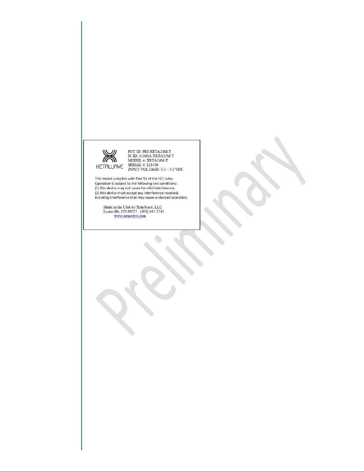
Note: Whenever any XetaWave LLC module is placed inside an enclosure, a label must
be placed on the outside of that enclosure which includes the module’s FCC ID and IC ID.
WARNING
These radio systems shall be installed by a RF/radio professional familiar with the
applicable rules. Installation of all antennas shall be performed in a manner that will
provide at least the MPE Distance from the direction of maximum radiation, to any user
or member of the public and consistent with the settings in the applicable antenna
installation compliance section below.
Exposure Compliance
FCC ID: PEJ-XETA24M-T
IC ID: 11169A-XETA24M-T
It is the responsibility of the licensee or user to guarantee compliance with the
appropriate MPE regulations when operating this device in a way other than described
herein. The installer of this equipment must ensure the antenna is located or oriented
such that it does not emit an RF field in excess guidelines as posted in the Canadian RSS102/Safety Code 6 of Health Canada, 47 CFR Bulletin 65/47CFR § 1.1310 of the Federal
Communications Commission, or the Council of European Union as appropriate.
3

22
/10/ cmmWmW
2
/(4
)(
cmmWmtExposureLi
nAntennaGaiDutyCyclemWowerConductedP
MPED
The XetaWave XETA24 uses a low power radio frequency transmitter. The concentrated
energy from an antenna may also pose a health hazard in the near field. People should
not be near the antenna when the radio link is operating as general practice and
maintain a safe distance as calculated below.
Note: Industry Canada and the FCC use the same RF power density level for their limits,
but express them in different units. The US/FCC/OSHA/ANSI use milliwatts per square
centimeter (mW/cm2) and Industry Canada uses Watts per square meter (W/m2).
Equation 1:
The following calculations are based off the Maximum Permissible Exposure
requirements as outlined by the FCC and IC.
The MPED (Maximum Permissible Exposure Distance) is calculated based on the limits
for a General Population/Uncontrolled Exposure in the 1,500 – 100,000 MHz frequency
band using the stated MPE power density limit of 1.0 mW/cm2 or 10 W/m2. The
following table provides safe distance for several power levels and antennas besides the
worst case for convenience.
To calculate safe distance:
Equation 2:
Where:
MPED is Maximum Permissible Exposure Distance or safe distance.
All quantities are calculated in linear or numeric quantities.
The exposure limit, MPED, and conducted power units must be consistent, mW and cm
for this case.
Duty cycle is set using packet sizes for master and slave. The highest duty cycle, 93%,
that can be set is 1600 transmit and 64 receive using a modulation of 57 kbps MSK.
Packet settings are set in the radio Network Configuration Menu. If the radio is a master
then master packet size is set to 1600 and slave packet size is set to 64. All radios in the
link must have the same master and slave settings. At Power up and with no data
transmitting, the radios will transmit or beacon with a duty cycle of 6 to 10% depending
upon modulation setting.
4
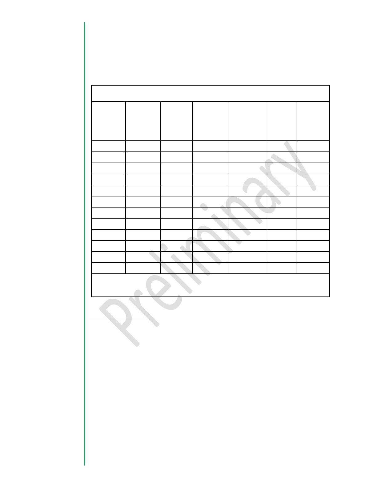
Table of MPE Safe Distance vs. Antenna Gain and Power Output Setting
Power
Out
Setting
(mW)*
Duty
Cycle
(linear)
Antenna
Gain
(dBi)
Antenna
Gain
(linear)
FCC MPE
Limit
(mW/cm2)
IC MPE
Limit
(W/m2)
Safe
Distance
(cm)
1000
0.93
20
100
1.0
10
86.03
1000
0.93
15
31.62
1.0
10
48.37
1000
0.93
12
15.85
1.0
10
34.25
1000
0.93
3
2.00
1.0
10
12.17
100
0.93
20
100
1.0
10
27.20
100
0.93
15
31.62
1.0
10
15.3
100
0.93
12
15.85
1.0
10
10.83
100
0.93
3
2.00
1.0
10
3.85
10
0.93
20
100
1.0
10
8.60
10
0.93
15
31.62
1.0
10
4.83
10
0.93
12
15.85
1.0
10
3.42
10
0.93
3
2.00
1.0
10
1.22
*The worst case is 1000 mW with an antenna with 20 dBi gain or greater or 86.03 cm
as power output is reduced as required by the appropriate regulating authority.
The limits for Industry Canada are in Watts per square meter and easily calculated from
equations 2 and then 1 above.
FCC antenna compliance
Since professional installation is required, standard RF connectors are used. Adapters or
custom coaxial cables may be required to connect the radio output connector to the
desired antenna.
Any antenna from a reputable manufacturer with desired bandwidth, gain/pattern
coverage, and have an input surge impedance of approximately 50 ohms can be used
provided the requirements of Title 47 CFR Part 51.247 (a), (b) and (c) are met, i.e.
conducted power of 1W (30 dBm) or EIRP of 4W (36 dBm) maximum in a PTMP
configuration. If the antenna gain is greater than 6 dBi, the power setting shall be
reduced by the amount the gain of the antenna exceeds 6 dBi. In other words the EIRP
cannot exceed 4W or 36 dBm for a PTMP Configuration. In a fixed PTP link configuration
you can increase the antenna gain to get an EIRP above 36 dBm but for every 3dBi
5

Transmit Power (dBm)
Antenna Gain (dBi)
EIRP (dBm)
30 6 36
29 9 38
28
12
40
27
15
42
26
18
44
25
21
46
24
24
48
23
27
50
22
30
52
increase of antenna gain you must reduce the transmit power by 1 dBm. The table
below shows the combinations of allowed transmit power / antenna gain and the
resulting EIRP.
Industry Canada antenna compliance
Under Industry Canada regulations, this radio transmitter may only operate using an
antenna of a type and maximum (or lesser) gain approved for the transmitter by
Industry Canada. To reduce potential radio interference to other users, the antenna
type and its gain should be so chosen that the equivalent isotropic radiated power
(E.I.R.P.) is not more than that necessary for successful communication.
Conformément a la réglementation d'lndustrie Canada, cet émetteur radio ne peut
fonctionner a l’aide d'une antenne d'un type et maximum (ou moins) Gain approuvé
pour l'émetteur par Industrie Canada. Pour réduire Ie risque d'interférence avec
d'autres utilisateurs, Ie type d’antenne et son gain doivent étre choisis afin que la
puissance isotrope rayonnée équivalente (PIRE) ne dépasse pas ce qui est nécessaire
pour une communication réussie.
This radio transmitter 11169A-XETA24M-T has been approved by Industry Canada to
operate with the antenna types listed below with the maximum permissible gain and
required antenna impedance for each antenna type indicated. Antenna types not
included in this list, having a gain greater than the maximum gain indicated for that
type, are strictly prohibited for use with this device.
Cet émetteur radio 11169A-XETA24M-T a été approuvé par lndustrie Canada pour
fonctionner avec les types d'antennes énumérés ci-dessous avec Ie gain maximal
admissible et l’impédance d'antenne requise pour chaque type d'antenne indiqué.
Types d’antennes ne figurent pas dans cette liste, ayant un gain supérieur au gain
maximum indiqué pour ce type, sont strictement interdites pour une utilisation avec cet
appareil."
6

Gain
Impedance
Type
dBi
Antenna
Manuf.
Part
Number
Input ()
Small, radio
connected,
omni-directional
3
Rubber Duck
Laird
MAF943
00
50
Base station
directional
11
Yagi
L-Com
HG824-
11LP-NF
50
Base station,
omni-directional
12
Tubular
vertical
TPLink
TL-
ANT2412
D
50
Base station,
Panel
19
Panel
ITElite
SRA0.9/2.
4/5
50
The installer of this radio equipment must ensure that the antenna is located or pointed
such that it does not emit RF field in excess of Health Canada limits for the general
population; consult Safety Code 6, obtainable from Heath Canada’s website www.hcsc.gc.ca/rpb.
The following antennas are approved for US & Canadian use as detailed below.
7

Specifications
1 Specifications (Preliminary and TBC)
1.1 Performance
8

1.2 Environmental
-40°C to +85°C operating temperature range. -55°C available. Exceeds MIL-STD-
810G methods 501.4 and 502.4.
95% operating humidity @ 40°C non-condensing.
Exceeds MIL-STD-810G methods 501.4 and 502.4.
Humidity storage satisfies MIL-STD-810G method 504.7
Shock & vibration satisfies MIL-STD-810G methods 514.5 and 516.5 3-axis 3G
vibration and 40G shock.
1.3 Security & Certifications
AES 256-bit encryption
Password authentication
FIPS 140-2 validation in progress
FCC, UL Class 1 Div 2 and ETSI
9

1.4 Mechanical / Physical Design
10

2.1 Menu System
2.1.1 Operating Menu – Status Page
2.1.2 Main Configuration Menu
11

2.1.3 Serial Port Configuration Menu
2.1.4 RF and Hopping Menu
12

2.1.5 Bit Rate and Modulation Type Menu
2.1.6 Network Configuration Menu
2.1.7 Advanced Settings Menu
13
 Loading...