

Xerox
Data
Systems
XIDlS
SIGMA 9 COMPUTER
Reference Manual
XoS
SIGMA
9
INSTRUCTION
LIST
(MNEMONICS)
Mnemonic Code
AD 10
AH
AI
AIO
AND
ANLZ
AW
AWM
BAL
BCR
BCS
BDR
BIR
CAll
CAL2 05
CAL3
CAL4
CB
CBS
CD
CH
CI
CLM 19
CLR
CS
CVA
CVS
CW
DA
DC 7D
DD
DH
•
DL
DM
DS
DSA
DST'
DW
EBS
EOR
EXU
FAL
FAS
FDL
FDS
FML
FMS
FSL
FSS
HIO
lNT
LAD
LAH
LAS
LAW
LB
LCD
Instruction
Add
Add Halfword
50
Add Immediate
20
6E
Acknowledge
4B
AND
44
Analyze
Add Word
30
66
Add Word
6A
Branch
Branch
68
69
Branch
Branch
64
65 Branch
Call
04
Call
06
Call
07
Call
71
Compare Byte
Compare Byte String
60
11
Compare Doubleword
51 Compare Halfword
21
Compare Immediate
Compare
39
Compare
45
Compare
29
Convert
Convert
28
Compare Word
31
79
Decimal
Decimal Compare
Decimal
7A
Divide
56
Decimal Load
7E
Decimal
7B
Decimal
78
Decimal Shift
7C
7F
Decimal
Divide
36
Edit Byte String
63
48
Exclusive OR Word
Execute
67
ID
Floating
3D
Floating
Floating
IE
3E
Floating
Floating
IF
Floating
3F
lC
Floating
Floating
3C
4F
Halt
Interpret
6B
Load Absolute Doubleword
1B
5B
Load
26
Load
Load Absolute Word
3B
Load Byte
72
Load Complement Doubleword
lA
Name
Doubleward
Input/Output
Word
to
Memory
and
link
on
Conditions
on
Conditions
on
Decrementing
on
Incrementing
1 102
2 102
3 102
4
with
Limits in Memory
with
Limits in Register
Selective
by
Addition
by
Subtraction
Add
Divide
Halfword
Multiply
Subtract
Arithmetic
Store
Word
Add Lang
Add Short 77
Divide Long
Divide
Multlply
Multiply
SiJbtract Long
Subtract
Input/Output
Absolute
Halfword
and
Set
Interrupt
Reset
Set
Register
Register
Short
Long
Short 77
Short
~age
60
'
60
59
120
68
57
60
64
101
100
100
101
JOO
102
66
87
67
66
66
68
67
67
72
73
67
81
82
82
63
80
81
81
82
81
63
89
68
99
77
78
78
77
77
77
119
58
50
48
51
49
47
49
Mnemonic
LCF
LCFI
LCH
LCW
LD
LH
LI
LM
LMS
LPSD
LRA
LRP
LS
LW
MBS
MH
MI
MMC 6F
MSP
MTB
MTH
MTW
MW
OR
PACK
PLM
PLW
POLP
POLR
PSM
PSW
RD
RIO 4F
S
SD
SF
SH
SIO
STB
STCF
STD
STH
STM
STS
STW
SW
TBS
TDV
TIO
HBS
UNPK 77 Unpack Decimal Digits
WAIT
WD
XPSD
XW
~ode
70
02
5A
3A
12
52
22
2A
2D
OE
2C
2F Load Register
4A Load
32
61
57
23
13
73 Modify
53
33
37
49
76
OA
08
4F Poll Processor
4F Poll
OB
09
6C
25 Shift
18
24
58
4C
75
74
15 Store Doubleword
55
2B
47
~5
38
41
4E
4D Test
40
2E
6D
OF
46
Instruction
Load
Load
Load
Load
Load'Doubleword
Load Halfword
Load Immediate
Lood
Load Memory
Load Program Status Doubleword 103
Load Rea I Address
Load Word
Move Byte String
Multiply
Multiply
Move
Modify
Modify
Modify
,
M~ltiply
OR Word
Pack Decimal Digits
Pull
Pull Word
Push
Push Word
Read
Reset
Subtract
Shift
Subtract
Start
Store Byte
Store
Store Ha I fword
Store
Store
Store Word
Subtract
Translate
Test
Translate
Wait
Write
Exchange Program Status Doubleword
Exchange Word
Name
Conditions
Conditions
Complement
Complement
Multiple
Selective
Multiple
and
Multiple
Direct
Input/Output
Floating
Input/Output
Conditions
Multiple
,Selective
Device
Input/Output
ond
and
Halfword
Word
Status 51
Pointer
Halfword
Immedi-ate
to
Memory Control 106
Stack
Pointer
and
Test Byte
and
Test Halfword
and
Test Word
Word
Reset Processor
Doubleword
Ralfword
and
Word
Byte String
and
Test Byte String
Direct
Floating
Floating
Floating
Control
Control
Control
Immediate
Page
55
54
48
48
48
47
47
54
50
106
53
47
86
62
62
98
64
64
65
63
68
83
97
96
120
120
96
95
108
120
69
61
71
61
114
55
56
56
55
56
56
55
61
87
118
117
88
84
108
110
103
55
Price:
$6.50
XDS
SIGMA
REFERENCE
FIRST
October
9
COMPUTER
MANUAL
EDITION
90 17 33A
1970
Xerox
© 1970, Xerox Data Systems, Inc.
Data
Systems/701 South Aviation Boulevard/EI Segundo,
California
Printed
90245
in U.S.A.
RELATED
PUBLICATIONS
Title
XDS
Sigma Glossary of Computer Terminology
XDS
Symbol/Meta-Symbol Reference Manual (Sigma
XDS
Macro-Symbol Reference Manual (Sigma
5/7
Computers)
5/7
Computers)
Publ
ication No.
90 09
90
90
57
0952
15
78
ii
CONTENTS
SIGMA
l.
Introduction
General
General-Purpose
Input/Output
Time-Sharing
RealMultiusage
Multiprocessor
Multiprocessor
Homespace
Multiport
Manual
Multiprocessor
Shared
SIGMA
2.
Central
General
Memory
Computer
Information
Information
Instruction
Main
Memory
Virtual
Homespace
Memory
Types
Address
Memory Address Control
Program
Interrupt
Internal
Externa I
States
Control
Time
Single-Instruction
Trap System
Trap
T
rap
Trap Masks
Trap
Trap Addressing
Nonallowed
Unimplemented
Push-Down
Fixed-Point
Floating-Point
Decimal
CALL
Processor
Trap
Register
9 SYSTEM
Characteristics
Capabi I ities
Features
Time
Features
Features
Memory System
Partitioning
Input/Output
9 SYSTEM
Processing
Registers
Control
Modes
Memory
Unit
and
Reference
of
Addressing
Modification
Status
System
Interrupts
Interrupts
of
an
of
the
of
Interrupt
Entry
Sequence
Condition
Arithmetic
Instruction
Detected
ConditIons
Altered
Features
Features
Interlock
Capabi
Control
ORGANIZA
Un
Format
Boundaries
Register
Real Memory
Doubleword
Interrupt
Interrupt
Code
Operation
Instruction
Stack
Overflow
Arithmetic
During HAnti cipateJl
Function
it
Storage
Address
Examples
Level
System
Occurrences_
Interrupts
Trap
Limit Trap
Trap
Fault
Trap
Fau Its
Bit
lity
nON
Trap
Fault
Trap
Trap
Operations
3
4
4
5
6
6
6
6
6
7
7
7
8
8
8
8
11
11
12
12
13
13
14
14
14
17
20
22
26
28
29
30
30
32
32
32
__
33
33
_______
33
33
33
33
35
36
37
37
38
39
39
39
_ 42
42
3.
INSTRUCTION
1
1
Load/Store
Analyze/Interpret
Fixed-Point
Comparison
Logical
Shift
Byte-String
Push-Down
Execute/Branch
CALL
Control
Input/Output
Instructions
Instructions~
Floating-Point
Zoned
Decimal
Decimal
Illegal
Overflow
Decimal
Condition
Stack
Push-Down
Branches in
Mode
Nonallowed
of
Instructions
Instructions
Program Status
Loading
Loading
Loading
Locks
Interruption
Read
(Mode 0)
Read
(Mode
Write
(Mode
Write
(Mode
I/O
Addresses
Processor Addresses
(Bits
Device
(Bits
I/O
Unit
I/O
Status Response 114
Status
General
REPERTOIRE
Instructions
Arithmetic
Instructions
Decimal
Accumulator
Instruction
Digit
Detection
Instruction
Code
Instructions
Instructions
Pointer
Condition
Real
______________
Branch
the
Memory
the
Access
the
Memory
_______________
of
Direct -Internal
__________
Instructions
____________
____________
Shift
__________
Numbers
Format
and
Sign
__________
Nomenclature
Settings
__________
__________
Doubleword
Instructions
Extended
Operation
Instruction
Doubleword
Protection
MMC
____________
Direct,
Interrupt
1)
_________________
Direct -Internal
0)
____________
Direct,
Interrupt
1)
____________________
Instructions
19-23)
___________
Controller
Addresses
24-31)---
Address Assignment
Information
Registers
for
_____________
________
Instructions
__________
________
__________
________
Detection
_________
(SPD)
Code
Settings
________
Addressing
Trap During
_________
Map
Write
Protection
Computer
Control
Computer
Control
__________
SIO
_____
_____
_____
_____
____
Execution
Controls
Control
Control
_
_
_
_
_
_
_
_
_
_
_
_
_
_
_
_
__
_________
______
_
_
_
_
__
44
99
99
101
102
102
106
107
107
108
109
109
110
112
113
113
113
113
113
114
116
iii
INPUT/OUTPUT OPERATIONS
4.
Operational Command Doublewords
Order
Memory
Flags
Byte
Control Command Doublewords
OPERATOR
5.
Processor Contro I Pane I
Contro I Mode
POWER
MEMORY
SYS
I/O
LOAD
UNIT
SENSE
NOT
HALT
WAIT
RUN
Program Status Doubleword
INSERT
CPU
INTERRUPT
ADDRESS
SELECT
DISPLA
INSTR
DISPLAY
DISPLAY
FORMAT
DATA
STORE
COMPUTE
Maintenance Controls
Alarm
Margins
PHASES
CLOCK
SNAP
MEMORY
OVERRIDE
SCAN
EXT
Operating Procedures
Loading Operation
Fetchi
Byte
Address 123 (USASCII)
Count
CONTROLS 127
CLEAR
RESET
RESET
ADDRESS
NORMAL
RESET
STOP
ADDRESS
Y (switch)
ADDR
(Indicator) 132
FORMAT
SEL
MODE
MODE
MODE
DIO
ng
and Storing Procedure 137
APPENDIXES
REFERE
NCE
A.
XDS
XDS
TABLES
Standard
Standard Character Sets
Symbols
and Codes
122
123
123
123
125
125
127 Hexadecimal-Decimal Fraction Conversion
127
·128
128
128
128
128
128
128
128
128
129 Timing Considerations
129 Effects of Memory Interference
129 Effects of Indexing
130 Effects of Indi rect Addressi
130
130
130
131
131
131
132
132
132
132
132
133
133
133
133
133
133
134
134
134
135
135
135
138
138
138
Contro I Codes
Special Code Properties
XDS
Standard 8-Bit Computer· Codes
XDS
Standard 7-Bit
XDS
Standard Symbol-Code Correspondences
Hexadecimal Arithmetic 144
Addition Table
Multiplication Table
Table of Powers
Table of Powers
Hexadecimal-Decimal Integer Conversion
Table of Powers
Mathematical
SIGMA 9 INSTRUCTION
B.
INSTRUCTION TIMING
C.
SYSTEM
D.
System Maintainabi I ity Features
GLOSSARY OF
E.
RELIABILITY
CPU
Features 167
Main Memory Features
Multiplexor
(MIOP)
High-Speed
Features
Communi
of
of
of
Two
Constants 156
Input/Output
Features
RAD
I/O
SYMBOLIC
cation Codes
Sixteen
Ten16
AND MAINTAINABILITY 166
10
LIST
Processor
Processor (HSRIOP)
TERMS
(EBCDIC)
ng
ILLUSTRATIONS
SIGMA 9 Computer System
A Typical SIGMA 9 System 9
l.
Central Processing Unit
2.
Information Boundaries
3.
Addressing Logic
4.
Index Displacement
5.
Virtual Addressing Modes)
Displacement
Index
6.
Addressing}
Generation of
7.
Virtual Addressing (SIGMA 9 Mode)
Generation of Effective
8.
Extended Addressi
Interrupt
9.
Operational
10.
Processor Control Panel 127
11.
Priority Chain
AI
ignment (Real and
AI
ignment
Actual Memory Addresses,
ng
States of an Interrupt Level
{Real
Extended
Virtual Address,
__
__
Table_146
Table_152
Real
138
138
139
139
140
144
144
145
145
156
157
158
158
158
158
158
166
169
169
170
171
vi
10
12
16
21
22
23
24
29
31
iv
Homespace Layout
1.
Computer
2.
SIGMA 9 Interrupt Locations
3.
Summary
4.
TCe
5.
Registers Changed
6.
Status Word 0
7.
Operating
of
SIGMA 9 Trap Locations
Setting for Instruction Exception
(XI4D')
Trap
an
Operand
Access
TABLES
and
Addressing Modes
at
Time
of
a Trap
Due
to
___
Status Word 1
8.
Status Word 2
9.
15
28
29
34
41
42 Indi
52
ANAL
10.
11.
12.
13.
14.
C-l.
YZE
Codes
Floating-Point
Condition Code Settings for
Instructions
Status Response for
Program Status Doubleword
Basic Instruction Timing
Table for
cation
SIGMA 9
Number Representation
I/O
Operation
Floating-Point
Instructions
(PSD)
53
53
58
74
76
115
129
J58
v
1.
SIGMA 9 SYSTEM
INTRODUCTION
The
XDS
SIGMA 9 Computer System
general-purpose
variety
for a
time-sharing
central
and
system
other
The basic system can be
the
for four million words. Memory access paths
creased
Input/output
input/output
devices.
The CPU has a large instruction
point
1I100k-ahead
cution
execution
(512K) words
16
of
independent
CPUs or lOPs. Each bank
address
banks. This multibanK, multiaccess memory subsystem with
interleaving
single
clude
port expansion
processors
transfer
concurrent
The SIGMA 9 computer design
SIGMA 7 computer, so
on SIGMA 9. Therefore, comprehensive, modular
ware,
operating
and
Reliabi lity,
significantly
A
an
lOP,
tem for diagnosis
continues
This manual describes
features, system organ
ations,
prbcessing unit (CPU), a main memory subsystem,
an
independent
element
elements.
user1s requirements. Main memory has addressing
from
and
with memory
modular units
ports
in
interleaving
memory bank designs. The SIGMA 9 system
up
to
data
requiring no reprogramming
uti I ity routines.
partitioning
entire
and
operator
digital
computer system. It
of
scientific,
applications.
performs asynchronously with
the
basic two ports to a maximum
capability
processors (lOPs),
decimal instructions. A
ll
enables
time.
and
systems, assemblers, compilers,
subsystem, consisting
attached
operation.
A large main memory
is
provided. The memory consists
of
each
memory unit
access to memory by
achieves
11
independent
capability)
high-speed
at
rates
with CPU instruction
maintainabi
improved
feature,
peripherals to be isolated
and
controls,
business
A basic system includes a
input/output
readi
Iy
can
be increased
device
set
the
CPU
to
accessing,
32,768 (32K) words
can
system performance far
up
to
lity,
over
for
repair
the
ization,
thereby
can
operates
be provided between
I/O
of
two types - multiplexor
RAD
I/O
three
that
SIGMA 7 programs will run
and
previous SIGMA computers.
example,
whi Ie
general
instruction
and
timing
is a high-speed,
is
designed
data
processing,
subsystem
expanded
that
special
overlap
be
up
to
processors (limited only by
processors - which
mill ion bytes per
execution.
is
compatible
is
avai
of
a CPU, memory
the
characteristics
..
Each major
respect
to accommodate
by
controllers,
includes
feature
instruction
reducing program
of
up
each.
expanded
12
processors -
asynchronously,
avai
lable,
mathematical
labi lity have been
permits faulty units or
from
primary system
set,
of
the
system.
and
to
space
can
be
of
12
ports.
adding more
and
I/O
floating-
called
exe-
to 524,288
of
up
to
The number
to
allow
either
and
adjacent
in
excess
can
I/O
can
second,
with
the
soft-
including
un
it,
the
sys-
and
I/O
oper-
in-
of
in-
GENERAL
A SIGMA 9 computer system has
characteristics
purpose, multiprocessing,
multiusage environments:
•
Word-oriented
which
halfword
(8-byte)
• Memory
(512K) words in blocks
and
blocks
256K to 512K (where K
• Direct addressing
entire
• Indirect addressing with or without
• Displacement index registers, automati
adjusting for
• Immediate
effi
•
16
general-purpose
blocks
isters
• Hardware memory mapping, which
nates memory fragmentation
program
• Four modes
and
• Memory
destruction
• Watchdog timer
•
Real-time
identification
time,
armed,
• Instructions with long
terrupted
• Automatic traps for error or fault
masking
under program contro
• Power
event
that
can
be addressed
(2-byte),
quantities.
expandable
65,536 (64K) words. Expansion proceeds in 32K
from
128K to 256K,
memory.
all
operand
ciency
and
of
16)
in
a multiusage environment.
relocation.
of
information
write
of
priority
and
up to 238 levels
enabled,
to
guarantee
capabi
fail-safe
of
power fai lure.
CHARACTERISTICS
features
permit
efficient
time-sharing,
memory
increased
reduce
memory
security
protection
critical
to
and
lity
for
(32-bit
and
word
from
of
= 1024 words).
capability
data
sizes.
instructions, for
registers,
data
access
areas
assure nonstop
interrupt system with
priority
and
triggered
execution
response
and
maximum
I.
automatic,
functioning
word plus
a Itered as
(4-byte),
131,072 (l28K) to
16,384 (16K),
and
in 64K blocks from
(real
speed.
expandable
transfer to
and
protection
and
protection.
preventing
of
memory.
assignment, fast response
that
can
by program
to
safe
real-time,
and
extended
post-indexing.
greater
and
virtually
provides dynamic
inadvertent
operation.
be
times
interrupts.
conditions,
recoverabi
shutdown
and
operating
in
general-
parity
bit)
byte
(8-bit),
doubleword
524,288
32,768
(32K),
mode)
ca
lIy
self-
storage
to
64
(in
from
reg-
elimi-
for system
automatic
individually
control.
can
be
in-
with
lity,
in
and
of
SIGMA 9 System
Multiple
•
for
Privi
•
in
multi usage
Complete
•
• Byte,
• Use
•
•
•
•
•
•
• Decimal
• Push-down
•
•
•
• Shift
interval
independent
leged
operations.
of
register-to-register
out
indirect
within
Multiple
Fixed-point
halfword,
Floating-point
and
long formats
normalization
un
der
Full
complement
OR,
exclusive
Comparison
between
registers).
Call
amically
and
allow
system functions
intervention.
metic,
plemented)
automatic
allocation,
recursive
Automatic
binary/BCD
systems.
Analyze
address
Interpret
interpretive
doubleword,
arithmetic,
point
timers with a
time
instruction
environments.
instruction
halfword,
all
memory-referencing
addressing
normal instruction format.
register
integer
word,
fu
II
program
operations,
limits (with limits
instructions
variable,
a program
hardware
edit,
and
stack
of
single
limit
subroutine
routine
conversion
and
instruction
computati
instruction
programs.
operations
including
searching
modes.
choice
bases.
logic for program
set
that
includes:
word,
and
operations,
and
operations.
arithmetic
and
doubleword modes.
hardware
with
control
of
OR).
without
pack/unpack.
operations
checking,
capabi
any
on.
(left
operations
significance,
and
contro
I.
logical
including
that
permit up
user-defined
access
operating
operations,
or
multiple
for
communication,
lity.
operations,
other
that
facilitates
that
increases
and
right)
logical,
shift,
of
resolutions
integrity
doubleword
instructions for
with or
post-indexing,
operations
checking,
operations
in
memory or
to
operating
including
(hardware
words, with
dynamic
weighted-number
of
circular,
and
with-
and
in
in short
zero,
and
all
(AND,
compare
to
64
dyn-
instructions,
system
arith-
im-
space
and
including
effective
speed
of
word or
floating-
Built-in
•
that
•
• Extensive
• Full
• Address stop
in
• Programmable "snapshot" registers
• CPU
•
Independently
•
lowing features:
•
•
•
reliabi
lity
and
include:
Diagnostic
tem
faulty
mine
faulty;
what
tected,
available
subsequent
communicated
tween
It
fau
mit
the
quickly
to
maintenance
diagnostic
snapshot
tion,
conditions.
variety
designed
recoverability.
Partitioning
figuration.
from
from
subsystem, consisting
input/output
peripherals,
ational
of a faulty
tinues
Direct
of a channel.
use
Up
to
by port limitations).
Multiplexor
channel
programs with
verification
unit; unit
the
and
physical component
system status and
parity
memory units
detection
operating
Stop on
Stop on
Stop when
of
register
thus
traps,
of
the
system by
busses. Thus,
system
operation.
input/output
eleven
capability,
and
functional
specific
memory
accurately
to
function
fault
location
error
logging.
for program
analysis.
checking
in
either
and
system or
determine a faulty
feature
personnel to:
any
instruction address.
any
memory
any
is
routines to
with
which
provide
CPU
and
enable
unit
operating
a high
features
SIGMA 9
selectively
processor
can
be
to
enable
while
I/O
processors
I/O
processors (MIOP) with dual
maintainabi
testing
retrieval
on
all
direction
and
processors, providing
location
that
word in a
referenced.
compare
known
determining
system
that
un
faulty
of
a CPU, memory
(lOP),
isolated
the
I/O
of
a full word, without
providing forsimultaneous
lity
capabilities
to
determine
testing
of
diagnosing
is
When a
fault
data
diagnostic
permits
reference
for
fault
degree
enable
its
units or an
diagnosis
primary system
system with
to
a unit
malfunctioning.
information
and logging for
and
on busses
capabi
lity
unit.
operator
address.
selected
that
contents
correct
system
detection
conditions,
of
system
can
be
partitioned
disabling
and
attached
from
the
and
(restricted
features
for:
sys-
the
deter-
that
is
to
analyze
fault
is
addresses
to
per-
program
page
enable
of
informa-
fault
of
system
recon-
them
entire
unit,
oper-
repair
con-
the
only
de-
are
be-
or
a
a
fol-
2
General
Characteristics
operation
and
concurrently,
eight
devices
of
up
to 24 devices on one
simultaneous
on
the
other
operation
channel.
channel,
of
with transfer rates
and
at
rates
37.5
up
second
transfer
up
to
60,000
inches per second with
to
20,800
bytes
bytes per
per
second.
• High-speed Rapid Access Data
(HSRIOP) for use with
•
•
Comprehensive
•
program
computers:
• Expands in
•
•
storage units,
up
to
three
Both
data
read
and
Up
to
32,000
put
test
compatible
grows.
Operating
(BPM), Batch Time-Sharing Monitor
Real-Time Batch Monitor
Time-Sharing System (UTS),
ating
System (XOS).
General-Purpose
FORTRAN IV,
and
FLAG.
allowing
million bytes
and
command
scatter-write
output
signals.
array
of
with
capability
systems: Batch Processing Monitor
Compilers: Extended
XDS
I/O
processor
XDS
high-speed
data
transfer
per
second.
chaining,
operations.
control signals
modular software
XDS
SIGMA
and
speed
(RBM),
and
FORTRAN IV-H, BASIC,
RAD
rates
for
gather-
and
that
5,
6,
and
as system
(BTM),
Universal
Xerox
Oper-
XDS
in-
of
is
• Displays:
acter
ups, as well as iight
function keyboard.
• Card equipment: Reading speeds up
cards
cards
EBCDIC
Line printers: Fully buffered with. speeds up
•
7
• Keyboard/printers:
• Paper
•
1,500 lines per minute; 132 print positions
to
with
also
acters
per second).
to
300
speeds
Graph
ing
300 steps per
meters
Graphic
generator,
per
minute; punching speeds
per
minute; intermixed binary
card
64
characters.
available
per second)
tape
equipment; Readers
characters
up
to 120
plotters: Digital
drift-free
to
3 inches per second.
display has
vector
codes.
with
and
per
characters
plotting
second
pen,
10
paper
second; punches with
in
at
standard
generator,
and
alphanumeric/
characters
tape
reader
punch
(l0
with
per
incremental,
two axes
speeds
from
char-
and c lose-
to
1500
up
to 300
and
per second;
(20char-
characters
speeds
second.
provid-
in
up
30
milli-
up
to
• Assemblers: Symbol, Macro-Symbol,
Meta-Symbo
• Library:
output programs.
• Business software: Data Management System
(DMS-l),
ANS COBOL,
Manage,
•
Application
cal
Programming System (FMPS),
Matrix
Simulation Language
Systems (CIRC-AC, CIRC-DC),
Display Library
Standard
•
ment including:
• Rapid Access Data
•
and
6.2
million bytes per unit; transfer
three
times from 17
Magnetic
systems, IBM-compatible;
operating
fer rates
other
I.
Mathematical,
Generalized
Manage,
and
1401
software: Functional
Generator/Report
(GDL-l).
special-purpose
mill ion bytes per second;
mi
IIiseconds.
tape
units:
at
150 inches per
up
to 120,000 bytes per second;
units
operating
utility,
Sort
and
Terminal-Oriented
Simulator.
Writer (GAMMA 3),
(S
L-1),
peripheral
(RAD)
files:
7-track
high-speed
second
at
75
inches per
Circuit
average
and
and
and
input/
Merge,
and
Capacities
XDS
Mathemati-
FMPS
Analysis
Graphic
equip-
rates
of
access
9-track
units
with
trans-
and
second
to
• Data communications equipment: Complete
of
character-oriented
line
oriented
terminals (including remote batch) to
computer system
and
equipment
via
local terminals
GENERAL-PURPOSE
General-purpose
by emphasis
Many operations
on strings
include
number conversion (for printing or display),
able
puter
features.
Floating-Point
available
Under program
checking,
causes a
hexadecimal
point number).
short
storage economy
sign ifi
decimal
input/output
system includes
trap
floating-point
cance
computing
on
computation
are
performed
of
characters.
arithmetic
at
standard speeds. The SIGMA 9
the
Hardware.
in
both short
control,
normalization,
when a
places
is
post-operation
occurs in
Significance
format
and
of
detected.
applications
Other
operations,
following
Floating-point
J32-bit)
the
user may
and
for
the
and
message-
to
connect
common
directly.
remote user
carrier
FEATURES
are
and
internal
in
floating-point
typical
binary to decimal
general-purpose
and
long (64-bit) formats.
select
significance
shift of more than two
the
fraction
checking
high processing
long format when
permits use
the
lines
characterized
data
handling.
format
characteristics
and
consider-
com-
instructions
optional
checking
of a f/oating-
of
speed
loss
zero
(which
of
and
are
the
and
Genera
I-Purpose Features 3
Decimal
instructions
struction
verting
and a genera
check
display
Indirect
linkages
separate
Displacement
displacement
without
ca
register
For
word,
may be
using
register
cesses
word, or doubleword. Incrementing by various
according
is
the
Instruction
short,
rapidly
execution
Translate
rapid
from a variety
verted
Arithmetic
operate
set
to/from
protection,
or
print
Addressing.
and
from
considering
lIy al ign themselves
may
example,
single-precision,
stored
the
same
contains
the
kth
to
always
by units
size
of
data
Set.
highly
assembled
time.
Instruction. The
translation
easi
Iy
on up
includes
the
packed
Ii
zed
edit
and
it.
permits
procedure
indexing.
permits
be
used on arrays with
in a matrix multipl
in a
second
index
the
element,
data
size
in a continuous
element
More
optimized
and
between
of
input sources
for
output.
Hardware. Decimal
to
31
digits plus
pack/unpack
format
instruction for
formatting, with
Indirect
keeping
accessing
its
quantity
value
data
sections
Indexing by means
size.
appropriately;
fixed-point
array
of
whether
is
not
required;
used.
than
100 major instructions permit
programs
minimize both program
Translate
any
instructions for
of
two digits per
zero
addressing faci
sections
for
ease
a desired unit
The
index
thus,
different
ication
numbers,
as
double-precision
for both arrays.
k,
then
the
it is a
byte,
instead,
array
table
to
be
written,
instruction permits
two
8-bit
can
be
handled
arithmetic
sign.
suppression,
punctuation
of
of
maintenance.
of a "floating"
registers
the
of
any
user always
codes; thus
This
conbyte,
to
litates
table
a program
of
data
automati-
same
index
data
sizes.
array
of
the
results
numbers,
If
an
index
ac-
halfword,
quantities
incrementing
regardless
which
are
space
and
data
and
recon-
in-
full
of
INPUT
jOUTPUT
Multiplexing
initialized,
CPU,
needs. The
CPU by using
mit both command
tervening
slow rates involving human
example) to transfer
up to
one
operated
Direct Data
program control
With this
or
from
need
not be used for
High-Speed
feature
one
RAD
This
high-speed
logic
sufficient
bytes per
this
enables
less
than
Input/Output
I/o processors
leaving
it free
to
MIOP requires minimal
channel
chaining
CPU
control.
rates
million bytes per
simultaneous Iy.
Input/Output
of
asynchronous or
feature
general-purpose
is
simi lar to
per
second.
40
information
relatively
RAD
Input/Output
multiplexing
channel
channel
to sustain transfer rates up
In a typical
a program swap into
milliseconds.
provide faster response to system
command doublewords, which
I/O
registers so
controller
contains
TIME-SHARING
Time-sharing
capacities
can
be performing a
share
of
interactive,
Other
requires on
is
the
among many users
the
available
"conversational"
users may be
Iy
final
ability
different
resources)
entering
output.
CAPABILITIES
Processor (MIOP).
operate
and
interaction
of
second.
(DIO). DIO
independently
interaction
data
chaining
equipment
rotating
can
infrequent
Processor (HSRIOP). This
is
time-sharing
or
speeds
(teletypewriter,
memory
Many
devices
facilitates
special-purpose
be transmitted
that
an
I/O
transmissions.
input/output
operating
the
buffering
to
out
of
main memory
FEATURES
of
a system
at
the
task (requiring a
and
mode with
work
to
same time. Each user
may be
the
to
be processed
Once
of
the
with
the
per-
without
range
from
devices
at
three
application,
share
on-line
of
can
in-line
devices.
directly
channel
except
that
a time.
and
priority
million
its
total
different
in an
computer.
that
in-
for
be
to
in
Conversion Instructions. Two
structions
internal
cluding
Call
up
machine
erating
Interpret
and
thus
other
Four-Bit
results by
every
flow, underflow,
without
4
provide
binary
BCD.
Instructions. These four instructions permit
to
64
user-defined
instructions,
system
Instruction. The
speeds
reducing
interpretive
Condition
automatically
instruction
requiring
Input/Output
for
and
any
services
interpretive
space
and
systems.
Code.
execution,
zero,
an
extra
Capabi
bidirectional
other
subroutines,
and
without
operations
minus,
generalized
conversions
weighted
as if
gaining
time
This simpl ifies
providing information on almost
instruction
lities/fime-Sharing
access
requiring
Interpret
such as
requirements for compi lers
including
and
pi
conversion
between
number system,
they
were
to
specified
its
intervention.
instruction simplifies
compilation,
the
checking
indicators for
us, as
appropriate,
execution.
Features
in-
handling
built-in
op-
and
over-
in-
of
The SIGMA 9 system provides
features
Rapid
another,
quickly
mit storing
registers by a
automatically
when
program status doubleword (PSD), which
description
operation,
PSD
Multiple
to
sponse time by
blocks. A
tions as
cally
described
Context
and
needed
loaded,
four blocks
needed;
selects
Saving. When
the
operating
easily.
in
a push-down
single
and
(also, by a
of
the
can
be
all
Register Blocks. The
of
reducing
distinct
the
below.
Stack-manipulating
instruction.
information in
current
stored
with a
16
general-purpose
block
the
program status doubleword
applicable
the
time-sharing
changing
environment
stack
single
user's environment
anywhere
single
the
need
can
register block.
can
of
1 to 16
Stack
the
stack
instruction). The
in
instruction.
optional
to
store
be assigned for
computer
from
one
user to
be
switched
instructions
general-purpose
status
is
updated
can
be
retrieved
current
contains
memory
avai
registers improves
and
and
labi lity
and
load register
different
automati-
the
mode
a new
entire
of
per-
of
up
re-
func-
User Protection. The
user to his own
set
operating system
tions
that
could destroy
correctly.
vents a user
Also, a memory
From
those assigned to him. It permits
areas for
reading
routines, while preventing
accessing instructions-in areas
Storage Management. SIGMA 9 memory
from
128K
sizes
provide the
for expansion.
the
memory map hardware permits storing a user's program
in
fragments as small as a
space
is
avai
(l31,072)words
capacity
To
lable;
contiguous block
map also
so
at
in
automatically
that
the
program appears
execution
time,
a different set
memory. The memory map
compatible SIGMA 7 mode in addition to providing
ability
words. Thus,
memory
output
to
locate
in
the
SIGMA 9's logical addressing
the
of
128K words regardless
Input/Output
quirements
Capabi I ity. Time-sharing
are
handled by
capabilities
Features
Nonstop
II.
Operation.
system continues to
due to failure
of
slave
mode feature restricts
of
instructions whi
certain
"privileged"
another
accessing
only,
such as those
access-protection
any
him
Ie
reserving
{master mode)
user's program
system
storage areas other than
him
to access
certain
containing
from
reading,
set
aside for other users.
writing, or
is
available
to 512K (524,288) words
make
yet
of
needed
storage
while assuring
efficient
page
a
II
fragments
at
use
of
available
of
512 words wherever
appear
execution
time.
the
as a sing Ie,
The memory
handles dynamic program
to
be stored in a standard way
even though it may
of
locations
any
128K-word (131,072) virtual program
system
each
for
SIGMA 9 can
can
always address a virtual
actua
time it
of
is
space
of
physical memory
lIy be stored
brought into
operate
four million
input/output
the
same
general-purpose
described under
A IIwatchdog
operate
special
even
I/O
"General-purpose
II
timer assures
in
case
devices.
of
halts or delays
Multiple
each
to
the
instruc-
if
used
pre-
public
sub-
in
potential
memory,
relocation
in a
the
size.
re-
input/
that
the
real-time
clocks with varying resolutions permit independent time
bases for flexible
allocation
of
time slices to
each
user.
to
in-
and
easy,
even
quick
progress.
each
group
In
establ ishing a con figuration
of
up
while a
to
16
interrupt levels
ity assigned in different ways
of
a problem;
not
affected
Programs
that
the
way interrupt levels
by
the
priority assignment.
deal
with interrupts
equipment sometimes must be
ment
is
actually
cia
I equipment,
IItriggered
struction. This
hierarchy
high-priority
pleted,
it may
ll
by
the
of
responses.
interrupt,
be
available.
any
SIGMA 9 interrupt level
CPU through
capability
after
desirable
the remaining portion so
other
to respond to
critical
real-time
to
checked
To
permit simulating this
execution
is also useful in establishing a
For
example,
the
to assign a lower priority
that
the
stimuli. The interrupt
can accomplish this by triggering a
which processes
rupts have been
Certain
instructions
described in
interrogate
to
restore
and
Nonstop
(on a ready/resume
become
respond
excessively
quickly. A built-in
the SIGMA 9 computer
length
of
Real-Time
occur
to
also
event
up
at
needed
/ or
to four
solution to meet
easy handling
the
remaining
handled.
(READ
Chapter
the
condition
that
system
Operation.
basis),
delayed
time.
Clocks. Many
specific
- for
the
instants.
example,
current
real-time
these
of
separate
data
DIRECT
3)
allow
the
of
the interrupt system
at a later
When
connected
the
computer
if
the
watchdog timer assures
cannot
be
real-time
Other
elapsed
time
of
day. SIGMA 9
clocks with varying degrees
needs. These clocks a
time bases
priorities.
meet
from
process
for
can
the
specific
are
programmed
specially
out
before
the
system,
have its
designed
the
is
can
of a single
in responding to a
urgent processing
interrupt
routine
is
routine
lower-priority
only
after
and
WRITE
program
other
DIRECT,
to
completely
at
level,
any
time.
to
special
delayed
special
can
device
for
devices
sometimes
does not
an
excessive
functions must be timed
timing information
time
since
a given
can
contain
Iso
and
relative
time
in
prior-
needs
is
equip-
spe-
be
in-
is
com-
to
free
inter-
that
of
re-
allow
time
is
REAL-TIME
Real-time
(1)
environment,
real-time
flexibi lity to handle a wide
applications
hardware
process itself,
that
(2)
provi des
speed
FEATURES
are
characterized
qu
i ck response to
great
enough to
and
(3)
varietyof
speeds. The SIGMA 9 system includes provisions for
following
Multilevel,
oriented
rupts by means
source
responded
be programmed.)
individually
disabled
real-time
computing features.
True Priority Interrupt System. The
SIGMA 9 system provides quick response to
of
up
to 224 external interrupt levels. The
of
each
to
according
interrupt
For
is
automatically
to
its priority.
further flexibi lity,
disarmed (to discontinue input
(to
defer responses). Use
ture makes programmed dynamic reassignment
keep
sufficient
data
(This
each
of
the
disarm/disable
by a need
an
extern a I
up with
input/output
types
at
varying
real-time-
inter-
identified
function must
level
can
acceptance)
of
priorities
for
the
the
and
and
be
fea-
Context
Rapid
interrupt-initiated
preserve
later,
while
of
environments must be done
1I0verhead
of
up
to
can,
if
relevant
tion address,
protection
Switching. When responding to a new
circumstances, a computer system must
the
current
setting
ll
time costs.
four blocks
operating
up
of
desired, be assigned to a
"information
about
current
key/etc.)
is
doubleword (PSD). A
PSD
anywhere in memory
to establish a new
environment/which
identifying a new block
can
SIGMA 9 system
environment
completely
thus preserve
instruction.
environment/for
the
new environment. This changing
quickly,
In
the
SIGMA 9 system/
with a minimum
general-purpose
specific
the
current environment (instruc-
general
single
register
kept
in a 64-bit
instruction stores
and
loads a new
block,
includes
of
general-purpose
and
change
through
the
execution
Rea 1-Ti
continuance
each
arithmetic
environment. All
memory-
program status
the
one
from
informatic:>n
registers. A
its
of a single
me
Features 5
set
of
of
one
registers
current
memory
operating
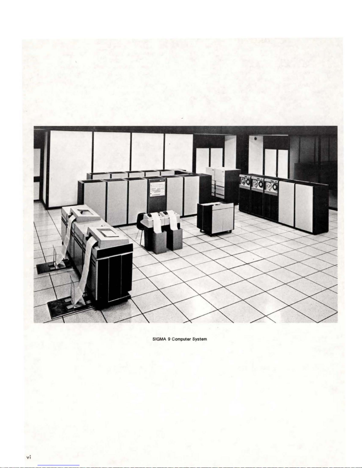
SIGMA 9 Computer System
vi
Memory
background
system
destruction
operating
feature
tions
Variable
tered
this
operations
arithmetic
included.
Direct
a
general-purpose
be
transm
because
prevents
of
in
real-time
data
Data
32-bit
occupied
iss
Protection.
programs
by
system
reading,
Precision
efficiently,
in
addition
operations
Input/Output.
word
with
ions.
Both foreground
can
be
run
concurrently
a foreground program
an
unchecked
control,
accessing
writing,
Arithmetic.
systems
can
be
register
relatively
SIGMA
background
the
memory for
and
are
16 bits or less.
9provides
to
fullword
(for
extended
For
transferred
so
that
infrequent
memory
instruction
Much
handling
an
(real-time)
is
protected
program. Under
access-protection
specified
acquisition.
of
the
halfword
operations.
precision)
asynchronous
directly
I/O
to or from a
channel
and
and
in a SIGMA
against
combina-
data
encoun-
To
process
arithmetic
Doubleword
are
also
need
not
nonperiodic
I/O,
Instruction
9
provides
required
each
and
SIGMA 9
multiprocessor system. It
processing units
(the
maximum memory port
SIGMA
a
This
wi"
cessor system.
Set.
The
large
SIGMA 9
the
user
the
computational
for
widely
IS
program
speed
of
differing
obtaining
length
and
application
and
runn ing
results
MULTIPROCESSING
is
designed
sum
of
both
9 system address memory uniformly.
section
allow
describes
growth from a monoprocessor
to function as a
can
and
up
to n input/output
types
of
processors
limitation
the
major
contain
instruction
data-handling
is
increased.
areas;
time
capabilities
therefore,
is
decreased,
FEATURES
shared-memory
up
to
four
processors
is
restricted
of
12). All processors in
features
of
SIGMA 9
to a multipro-
set
central
by
the
that
MULTI
As
implemented
bines two or more
difficult
cation
the
application
Because
time
tions in a
that
useful
capability
usage
puter
Priority
ments
interrupt
With it
proper
without
lengthy
Quick
duce a quick-response
rapid
fit
able
Memory
only
guarantee
real-time
general
because
most
the
base,
prove
in
applications.
features
Interrupt.
operate
system (as in
the
order,
the
execution
Response. The many features
context
all
users
at
any
Protection.
protect
in
the
computer
computing
of
its
difficult
it
multiusage
valuable
others,
makes
computer system corresponds qui ck Iy,
the
appl
multiusage
that
includes
SIGMA 9 system has
is
uniquely
for
although
SIGMA 9 particularly
The
are
described
In a multiusage
asynchronously.
to
the
many demands
high
overhead
time,
saving,
because
instant
each
more
for useful work.
user from
integrity
ications.
USAGE
SIGMA
severe
environment.
SIGMA
system (multiple
multiple
The memory
FEATURES
9 system, IImultiusage
application
problem
requirements.
problem
one
or more
been
qualified
certain
of
in
major
costs
and
of
every
programs
application
different
SIGMA
below.
Thus,
9)
is
of
extensive
push-pull
the
machine's
protection
other
areas.
is
the
real-time
is a time-sharing
real-time
designed
for a
mixtureof
Many
hardware features
areas
ways. This
effective
9 multi usage
environment,
having a true
especially
being
made
complicated
storage
that
combine
register
operations)
power
features not
user,
they
essential
ll
com-
The most
appli-
Similarly,
processes.
on a
real-
applica-
are
equally
multiple
in
mu
Iti-
com-
many
ele-
priority
important.
and
in
upon
it,
programming
allocations.
to
pro-
blocks,
bene-
is
avai
also
to
critical
MULTIPROCESSOR
In
a multiprocessor system,
often
need
(CPUs)
This
resource
peripheral
process.
required
LOAD
AND
position
store
cycle
previously
to
be
IIset"
On
the
other
a
zero,
the
and
simultaneously
processor.
device
SIGMA
multiprocessor
of
the
of
set
and
resource
exclusive
may be a region
or,
9 has a
SET,
unconditionally
referenced
the
memory
by
another
the
testing
hand,
in some
interlock.
if
the
is
allocated
the
interlock
INTERLOCK
the
central
control
of
memory, a
cases, a specific
special
instruction
memory
operation.
processor,
program
sign bit
to
The
sets a
proceeds
of
the
is
processing units
of
a system
particular
software
to
provide
special
111"
bit
location
If
the
the
set
during
this
bit
interlock
to
tested
testing
for
any
another
processor,
resource.
this
instruction,
in
the
sign
the
had
been
is
said
task.
location
other
re-
is
HOMESPACE
Since
all
processors in a multiprocessor system address
ina
un
i form
memory
vate
memory
and
interrupt
This
private
1,024 words for
real
with
tions,
1-
tions,
ters,
occupy
remaining words in
private,
that
memory
address
interrupt
plus
the
the
independent
manner,
is
un
locations,
is
each
CPU. Each Homespace
zero.
locations,
16
locations
first
the
storage
MUL
TIPORT
ique
320
it
is
necessary
to
each
processor for its
I/O
communication
called
Homespace region
The
implicitly
and
that
locations
by
MEMORY
Homespace
assigned
lOP
commun
are
reserved
of
Homespace. The
the
CPU.
SYSTEM
to
locations,
and
region
ica
ti on
for
can
be
reta
ina
trap
consists
trap
loca-
loca-
the
regis-
used as
pr
etc.
of
begins
i-
Input/Output.
speeds,
needs
both in terms
6
the
of
Multiusage/Multiprocessing
Because
SIGMA 9 I/O
many
different
of
equipment
of
its
wide
system
application
and
programming.
range
of
simultaneouslysatisfiesthe
areas
economically,
Features
capacities
and
SIGMA 9 has growth
unit. A basic
ory
16K
words
each,
in
operating
when
addressed
capabi
I ity
of
up
to 12 ports per mem-
memory unit consists
which
each
bank
can
by two
of
the
of
two banks of
be
concurrently
possible
12
ports.
This system
and
provides large amounts
to multiprocessor systems.
SIGMA 9 has manual
units. Thus, besides its primary
throughput
processor system
can
system busses. Faulty units
ational
units to be
A multiprocessor control function
cessor systems. This function provides
1.
architecture
MANUAL
capabi
is
be
partitioned
system. Reenabling
returned
MULTIPROCESSOR
Control
(External DIO), used for
of
the
allows flexibi lity
of
PARTITIONING
partitioning
lity, a
secondary
its fai I-soft
by
selectively
are
to
service.
CONTROL
External Direct
memory bandwi
CAPABILITY
capability
advantage
advantage
abi
lity. Any SIGMA 9 unit
disabling,
thus isolated
the
connection
is
provided on a
controlling
in
growth patterns
dth,
for
all
of
increased
of a multi-
it
from
from
allows
FUNCTION
II
three
basic features:
Input/Output
system
essentia I
system
the
the
oper-
repaired
multipro-
bus
maintenance
AID
converters.
2.
Central
3. Interprocessor interrupt
one
processor
cessor
control
that
an
and
of
to
action
special
system
directly
SHAREDINPUT/OUPUT
Provisions
system for
cessor. This is,
HIO instruction to
or
cess. However,
process
This
uration
action
resolution problems.
have
been
made in a SIGMA 9
any
CPU
to
direct
any
CPU
can
begin,
the
end-action
is
directed
feature
control switches) allows
tasks to a single processor and avoids
at
one
(accomplished by
purpose units such as
partitioning.
connection,
signal
is
to be
I/O
issue an
stop, or
sequence
of
the possible four CPUs.
setting a pair
dedicating
another
taken.
actions
SIO,
test
a !lowing
mul
to
any
no,
any
of
I/O
pro-
tiprocessor
I/O
TDV,
I/O
pro-
the
I/O
of
config-
end-
conflict
pro-
Multiprocessing Features 7
2.
SIGMA 9 SYSTEM
ORGANIZATION
The
primary
system, as
units,
elements
as a group
cati
ng
asynchronously
overlapping
greater
system
duction
subsystem performs
of
digital
selected
expanded
to
16),
cluding
ber
of
elements
illustrated
memory
wi
primarily
central
units,
permit
of
program-control I ed
th a common memory. Each subsystem
and
the
operation
speed
(when
tasks
while
information
peripheral
by
increasing
increasing
MIOPs
and
processors (up
CENTRAL
This
section
SIGMA 9 central
and
data
control.
memory
in Figure 2.
describes
formats, information
Basically, a SIGMA
and
an
arithmetic
of a basic
in Figure
and
input/output
the
total
computer
semi-independently,
of
the
circumstances
performs
overall
each
lOP
the
tasks
associated
between
devices.
the
number
the
number of lOPs (up
HSRIOPs), or by
to
PROCESSING
the
organization
processing
unit
processing,
and
SIGMA 9 computer
1,
are
central
processors. These
system
subsystems commun
other
permit).
control
(MIOP
the
main
A
basic
4).
to
automatically
subsystems for
and
or
HSRIOP)
wi
th
memory
system may be
of
memory units (up
to
increasing
UNIT
and
operation
in terms
9 CPU consists
control
unit
of
and
as
processor
be
viewed
i-
operates
A
CPU
data
re-
the
exchange
and
11,
in-
the
num-
of
instruction
program
of
a fast
illustrated
sub-
the
The
CPU
has
three
storage
for
codes
protection
computer
Memory
standing
and
A
virtual
used by a
the
of
data,
It
may
addresses
through
loading
during
clude
addresses,
gram,
An
actual
(memory address
location
by
the
addresses
ware.
of
a memory
associated
codes.
is
in
Map.
of
the
actual
address.
address
machine-level
location
of
or
the
also
be
are
derived
an
assembly (or
process.
a program's
all
instruction
and
as
well as those addresses
address
for
storage
execution
are
fixed
(See
"Main
MEMORY
the
Two terms
memory mapping
an
location
an
addresses used as
CONTROL
high-speed
map,
with
the
memory
This
storage
master or
is a value
instruction,
explicit
Virtual
execution.
addresses,
is a value
register)
or
sequence
and
Memory" for
master-protected
are
pertaining
program,
of a data
quantity.
from programmer-suppl ied
compilation)
addresses may
used
to
retrieval
of
dependent
STORAGE
integrated-circuit
memory
essenti al
access a specific
an
access
map,
can
be
concept:
and
the
location
address
Normally,
process
Thus,
virtual
data
addresses,
counts
computed
within
of
information,
instruction.
on
the
further
protection
and
memory
changed
to a proper
virtual
to
the
which
of
(indirect
followed
also
addresses
within a stored
by
the
memory
wired-in
details.)
memories
write-
when
mode.
under-
address
logical
be
the
space
designates
an
element
address).
virtual
labels
computed
indirect
program.
unit
memory
as
required
Thus,
actual
hard-
the
by a
in-
pro-
GENERAL
An
integrated-circuit
general-purpose
CPU. These 16 reg i sters
register
a
register
4
ister
block
selects
are
block
master
fied
(0 through 15 in
decimal
fixed-point
temporary
formation such
General
ters,
accumulator
31
used when a
the
general
16
referred
pointer
or
master-protected
Each
general
by a 4-bit
notation).
registers
and regi sters 12 through 15 may be used as a
digits
plus
registers,
block. A SIGMA
blocks. A 4-bit
pointer)
block
registers
to
accumulator,
data
in
currently
selected
as
the
can
be
register
code
in
decimal,
Any
storage
as a data
1 through 7 may
capable
sign.
Registers 12 through
dec
imal
REGISTERS
memory,
the
current
changed
in
the
location,
of
instruction
consisting
is
used
within
of
fast memory
9 system may
control
Program
mode.
the
or
general
floating-point
address,
containing a decimal
available
by
the
register
when
current
range
0000
X'O'
register
or
count,
is
field
Status
register
the
register
through
to
be
executed.
of
sixteen
the
SIGMA
are
referred
contain
(called
to
block.
computer
through
accumulator,
contain
used as
the
Doubleword (PSD)
a program. The
block
The
is
block
1111
X'
F' in
may
be
used as a
control
pointer,
index
number
15
are
always
32-bit
9
to
as
up to
reg-
pointer
register
in
the
is
identi-
hexa-
in-
etc.
regis-
decimal
of
The memory map
relocation
the
into
whatever
map
program,
system.
When
the
word,
memory as
o
through
addresses
ple,
address
general
in
of
in memory
When
addresses
regi
are
order
from
cess
into
memory map
512-word
transforms
the
memory map
all
if
the
ster
transformed into
portion
the
is
described
pages
pages
into
actua
memory map
virtual
actual
15
are
rather
an
instruction
where a result
register 5 in
location
computer
in
the
addresses.
of
memory map. (The memory map
feature
discontinuous
is
of
space
virtual
control
address
addresses.
always
than
range
the
in
provides
in
effect,
and
distributed
are
addresses,
I addresses, as
is
not
bit
in
values
used by
as memory addresses. Thus, for
uses a
is
to
be
the
current
5.
is
operating
0 through 15
However,
actual
addresses,
virtual
address with a
the
section
for
segments
any
program may
throughout
available.
as
seen
seen
in
effect,
the
program status
above
Virtual
all
addresses in
the
CPU
virtual
address
stored,
register
with memory
are
vi rtual addresses
by
"Memory Address Control
dynamic
of
memory. When
be
memory in
Thus
the
by
the
individual
by
the
memory
as
determined
15
are
used by
as
general
of
the
result
is
block
map,
still used as
replacing
value
obtained
replacement
program
broken
memory
by
double-
the
the
range
register
exam-
5 as
the
stored
instead
virtual
general
above
the
high-
pro-
15
II
• )
8
SIGMA
9 System
Organization
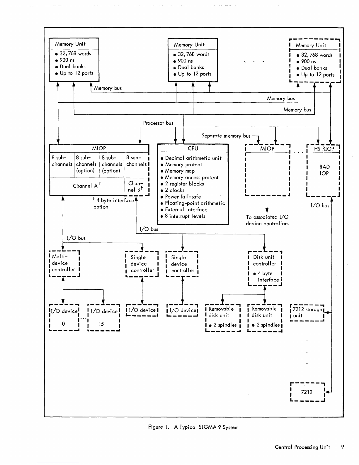
Memory
•
.900
• Dual banks
•
32,768
ns
Up
to 1 2 ports
Unit
words
t Memory bus
Processor bus
Memory Unit
•
32,768
• 900
• Dual banks
•
Up
to
ns
words
12
ports
j
r---------,
I Memory
I I
I •
I • 900
: • Dual banks :
1 •
L.
Memory bus
Memory bus
Unit
32,768
Up
________
j j J
to
ns
12
words I
ports 1
...I
I
I
1
MIOP
8
sub-
channels
'---r-----~-----
.--
•
Multi-
:
device
1
controller
Io
__ .-__
,..._.:.~
1
1/0
I 1 1
•
I a • I
..
-----1
8
sub-
channels I channels I channels
(option) I (option) I :
Channe
I/O
bus
1
~--1
1
1
•
J
j~
__
... . __
devicel• •
." " "I
I 8
sub-
I 1
t
I A
t 4 byte i nterfa
option
1
__
I/O
device
15
•
_____
.,
....
I 8
sub-
____
Channel B
--I'" - ..J
ce
j
..
__ 1 __
: Single
I
device
~~j~~~
•
I/O
1
L-
_____
1
I
t
I/O
devi
I
i
1
1
1
I
bus
ce
~-....&.
• Decimal
• Memory
• Memory map
• Memory
•
2 register blocks
• 2 clocks
• Power
•
Floating-point
• External
• 8
interrupt
, .
__
.:
• 1
~:~I~~:~
I I
I/O
.I
....
,
,Ir
......
------....
fail-safe
~
__
Single :
device
Separate
CPU 1
arithmetic
protect
access
protect
arithmetic
interface
levels
....
•
..
____
devi
I Removable •
ce·1
....
•
disk
I I
I • 2 sp i
L.
memory bus
unit
__ i __
_____
unit
nd
...,
I
I es I
~
~
r-------,
1 1
1 1
1 1
1 1
1 I
1 I
: 1
....
---r---
To
associated
device
r--~--'
• Disk
I
control I
I •
I • 4
, 1
MIOP
controllers
If
unit
byte
er
.
I
" " .
J
I/O
I
I
I
,
r
-HS"Ri'O'P'
l
I •
• •
•
RAD
• lOP I
1 1
• 1
1 1
L
_____
I/O
I
J
j~
bus
L-~Jte~~eJ
r--
I Removable I
I disk
I I
I •
L
--...,
unit
2 spindles I
_____
r-----...,
17212
•
I
unit
..
-I
storage!
-----
...
•
....
Figure
1.
A Typical SIGMA 9 System
r-----'
I 7212
• I
L
Central
_____
Processing
~
..
.J
Unit
9
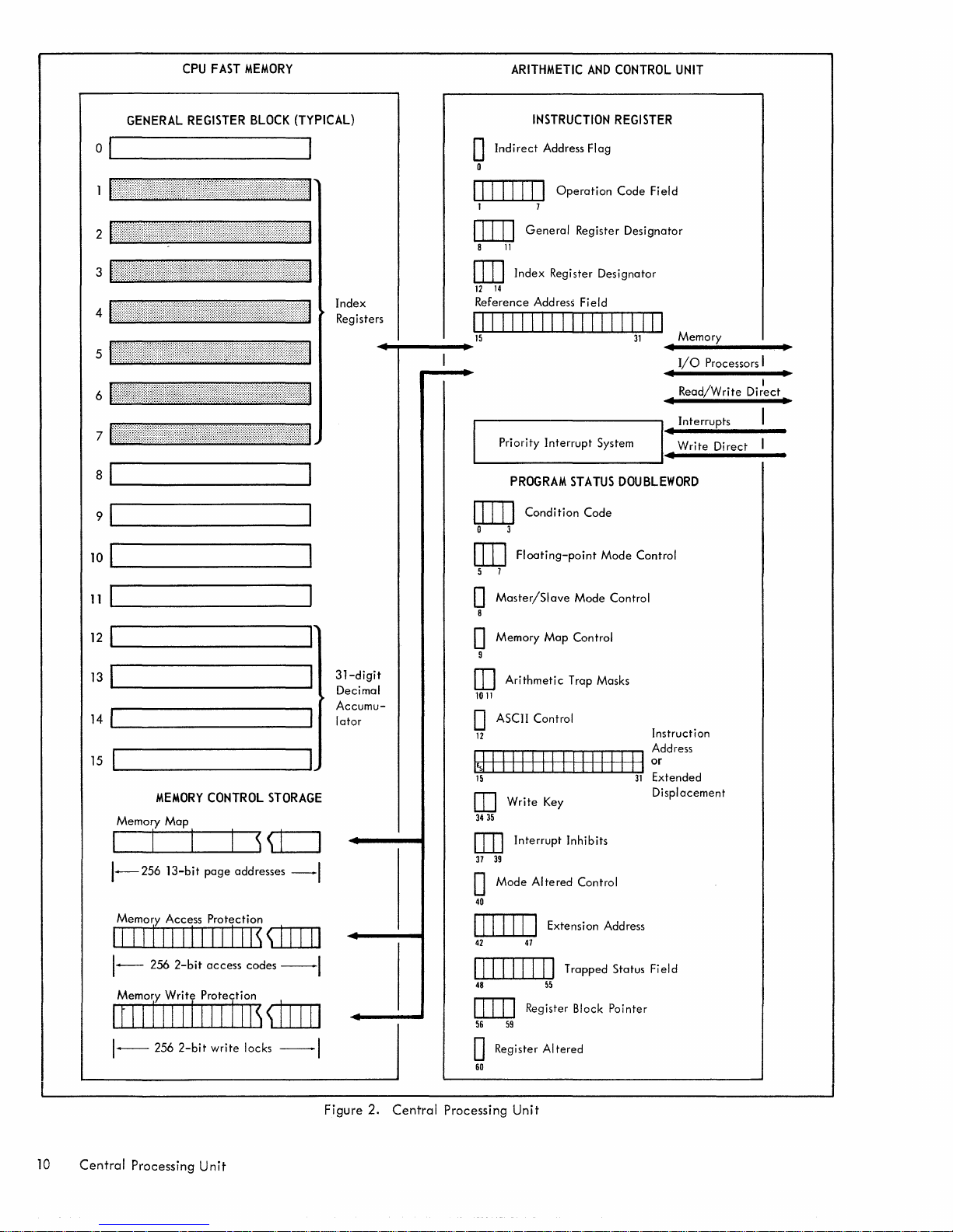
CPU
FAST
MEMORY
ARITHMETIC
AND
CONTROL
UNIT
GENERAL
REGISTER
BLOCK
(TYPICAL)
a I I
::::::::::::::::::::::
1 {:tttt,
2
3
4
5
6
7
8~1
9~1
10~1
.:.'
:::::::}::,:::::::::,::,,:::::,:
I
r::::I:::::
:{:'::::::.:.::::\::::::\/:?:
t·················
1:::::::::::::::::::1:11:::
1:::::::::::::::I:I:::::::::t:::::::::::
1:::::::::I::r:::I::::::::::::::::::::::::::::::::::::::::::
1:::::::::::::::::::tf:tII:::::::::::::::::::t:::::::::::::::::::::::::::::::::::::I::::::::::::::::::::::::::::II::::tl
II::::i::::::::I:I::::i:i(:::::it:t::i:::::i:::i{:::::::::i::t:t::I:::::
______________
______________
________________
.:.:.:.::
... : ..
::.:)t::::::·
.::::::::::,.,:::;::,
:,,:,::::::':'
,:::::::::::}::::}}:::,::}
...
:::::::::'::::::::::::::;:;:;:;:;:;:;:;:;:;:;:::::
:-:.:.:.:.:.:.:.:.:.:.:.:.:.:.:.:.:.:.:.:-:.:.:.:-:.:
.':::':::::':::::::::::::::::::.
:':-'-:':-:"':""':'::':::',::':':::'::::':':':'
:::::::::::::::::::
:::::::,.:':'::r:::::::'::::;::.:?::::!:!:::!}
::::::::}~:::
f't:::t::}::::::'::::
.:.:':'::'::'::':::':::'::'::"::::"::':.:::·1
.
:tI::::::::It·::1
':':':':':':':""1
':::r:::r::;
:::::I::::::I
i:::::::
J:::::::j::::!j@t::::::::::::1
Index
Registers
I:::::]
~
~
~
~
........
--
INSTRUCTION
o
Indirect
o
III
1 7
DIIJ
8
OJ]
12
14
Reference Address Field
I1111111111111111111
15
...
.------------,1
IIII
General
11
Index
Priority
Address Flag
I
Operation
Register Designator
Interrupt
REGISTER
Code
Register Designator
System I
I
PROGRAM
OJ]]
o 3
[ill
5 7
Floating-point
Condition
STATUS
Code
Mode
DOUBLEWORD
Field
Memory
31
I
I/O
I I
Read/Write
I •
Interrupts
I
Write
I
Control
Processors I
Direct
Direct
I
I
11
~I
________________
12~1
________________
13~1
________________
14
~I
__________________
15
MEMORY
Memory
1-256
Memory Access Protection
II I I
III
1--
256
Memory
It
IllllllllllllsffiIIJ
1-----
256
Map
13-bit
1IIIIII1
2-bit
Write
Protection
2-bit
CONTROL
page
addresses
access
write
~
STORAGE
-I
~
~"'-+-'-II"""""""I
codes
--I
locks
--I
~
~
~
II
31-digit
Decimal
Accumu-
lator
o
Master/Slave
8
o Memory
9
[I]
Arithmetic
1011
Map
Trap Masks
Mode
Control
Control
D ASCII Control
\I
I I
Instruction
or
31
Extended
Displacement
12
r-r-,...,...,...,..-r-r""T"'"'1I'"""T'"",....,...,...,..-r-r-, Add r e
IJ
I I I
II
15
OJ
3435
OJ]
37 39
o
40
III I II
42 47
II I II "
Write
Key
Interrupt
Mode
Altered
I Extension Address
Inhibits
Control
IIIIIIII1 Trapped Status Field
48
IllJJ
56 59
o Register
60
55
Register Block Pointer
Altered
ss
10
Central
Processing
Unit
Figure
2.
Central
Processing
Unit
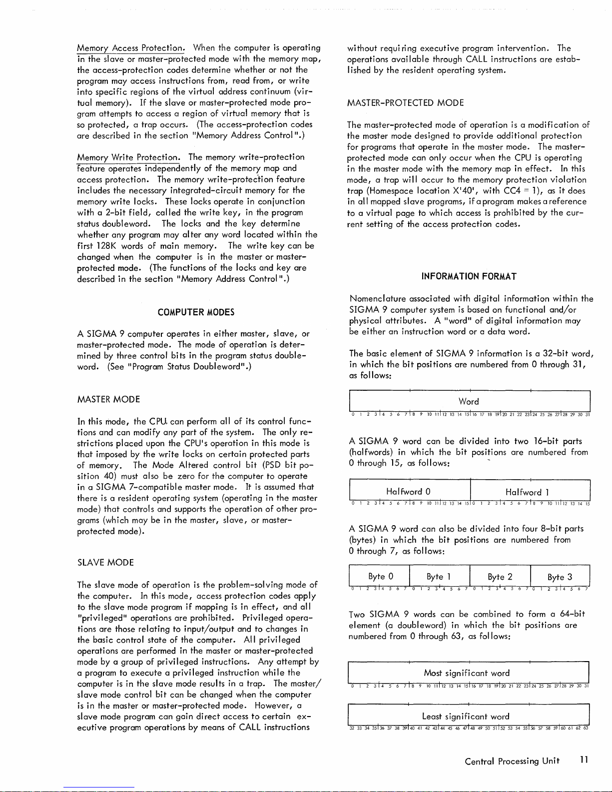
Memory Access
in
the
slave
the
access-protecti
program may
into
specific
tual memory). If
gram
attempts
protected, a trap
so
are
described
Memory
feature
access
Write
operates
protection.
includes
Protection.
or
master-protected
access
regions
to
access
in
the
Protection.
independently
the
necessary
When
on codes determ i ne
instructions
of
the
virtual
the
slave
or
master-protected
a region
occurs.
section
(The
"Memory Address Control
The memory
The memory
integrated-circuit
memory write locks. These locks
with a
2-bit
field,
called
the
write
doubleword.
status
whether
any
program may
first 128K words
changed
protected
described
when
mode. (The functions
in
the
The locks and
alter
of
main memory. The
the
computer
section
"Memory Address
is
the
computer
mode with
the
whether
from,
read
from,
address continuum
of
virtual
memory
access-protecti
write-protection
of
the
memory map and
write-protec'tion
memory for
operate
any
key,
the
word
in
conjunction
in
the
key
located
write
in
the
master
of
the
locks
Control".)
is
operating
memory
or not
or
write
mode
that
on
codes
feature
program
determine
within
key
can
or
master-
and
key
the
(virpro-
".)
the
are
map,
is
the
be
without
operations
I ished
requi
by
ri
ng
available
the
resident
executive
MASTER-PROTECTED
The
master-protected
the
master mode
for programs
protected
in
the
master mode with
mode, a trap
trap
(Homespace
all
mapped
in
to a virtual
rent
setti
ng
that
mode
will
page
of
designed
operate
can
occur
location
slave
to whi ch
the
access
INFORMATION
through
operating
program
CALL
intervention.
instructions
system.
are
MODE
mode
of
only
operation
to
provide
in
the
master mode. The
occur
when
the
memory map in
to
the
memory
1
X140
,
is a
modification
additional
the
CPU
protection
is
effect.
protection
with CC4 = 1), as
programs, if a program makes a
access
is
protection
prohibited
codes.
by
FORMAT
The
estab-
master-
operating
In
this
violation
it
does
reference
the
cur-
of
A
SIGMA 9 computer
master-protected
mined by
word.
MASTER
In this
tions and
strictions
that
of
sition
in a
there
mode)
three
control
(See"
Program Status
MODE
mode,
the
can
modify
placed
imposed by
memory. The Mode
40) must
SIGMA
7-compatible
is a resident
that
controls
grams (which may
protected
SLAVE
The
the
to
"privileged"
tions
the
operations
mode
a program
computer is in
slave
is in
slave
ecutive
mode).
MODE
slave
mode
computer.
the
slave
are
those
basic
control
are
by
a group
to
mode control
the
master or
mode program
program
In
mode program
operations
relating
performed in
execute a privileged
the
COMPUTER
operates
MODES
in
mode. The mode of
bits
in
the
Doubleword".)
cpu.
can
perform all
any
part
of
upon
the
CPUls
the
write
locks on
Altered
also
be
zero
for
master mode. It
operating
and
be
of
operation
this
state
of
privileged
slave
bit
system
supports
in
the
master,
is
the
mode,
access
if
mapping
are
prohibited.
to
input/output
of
the
computer.
the
master
instructions. Any
mode results in a
can
be
changed
master-protected
can
gain
direct
operations
by
means
either
master,
operation
program
the
operation
certain
control
the
status
of
its control
system. The
in this mode
protected
bit
computer
is
(operating
the
operation
slave,
or
problem-solving
protection
is
in
effect,
Privileged
and
to
All
or
master-protected
instruction
trap.
when
mode.
access
of
However,
to
CALL
slave,
is
deter-
double-
func-
only
parts
(PSD
bit
to
operate
assumed
in
the
master
of
other
master-
mode
codes
apply
and
opera-
changes
privileged
attempt
while
the
The
master/
the
computer
certain
instructions
or
re-
is
po-
that
pro-
all
in
a
ex-
of
by
Nomenclature
SIGMA 9 computer
physical
be
either
The
basic
in which
associated
attributes.
an
instruction
element
the
bit
positions
with
digital
system is based on
A "word"
word
of
or a data
of SIGMA 9 information is a
are
numbered from 0 through
as follows:
SIGMA
A
(halfwords) in which
9 word
can
the
be
divided
bit
positions
o through 15, as follows: '
A
SIGMA
(bytes) in which
o through
Two
element
numbered from 0 through
9 word
can
also
the
bit
7,
as follows:
Byte 1 Byte 2
234567012345
SIGMA
9 words
can
(a doubleword) in which
be
divided
positions
be combined
63,
as follows:
information
functional
digital
word.
into
are
into
are
numbered from
the
bit
within
and/or
information
32-bit
two
16-bit
numbered from
four
8-bit
to
form a
positions
the
may
word,
31,
parts
parts
64-bit
are
Central
Processing
Unit
11
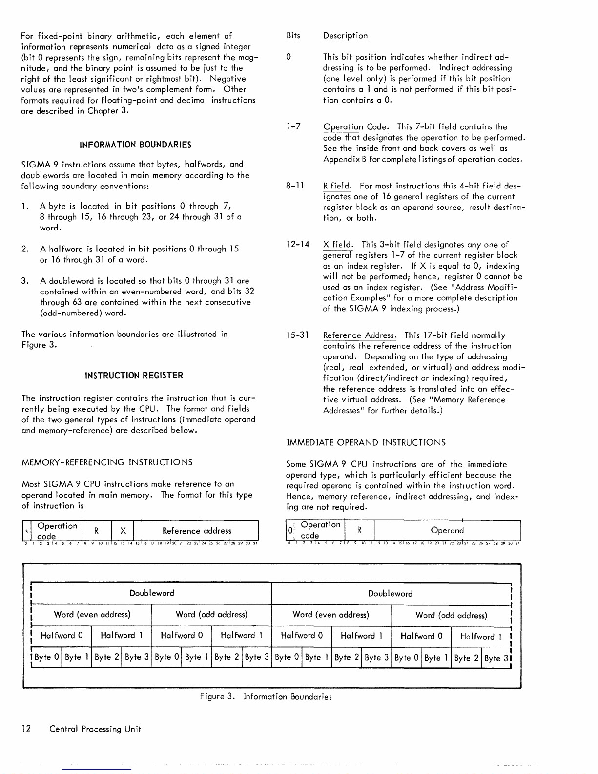
For
fixed-point
information
(bit 0 represents
nitude,
right
values
formats
are
and
of
the
are
required
described
binary
represents
the
the
binary
least
significant
represented
for
in
Chapter
INFORMATION
SIGMA 9 instructions
doublewords
following
1. A
8
word.
boundary
byte
is
through
are
located
15,
located
16 through
arithmetic,
numerical
sign,
remaining
point
is
or
in
two's
floating-point
3.
BOUNDARIES
assume
that
in
main
conventions:
in
bit
positions 0 through
23,
each
data
as a signed
bits
represent
assumed
rightmost
complement
and
bytes,
memory
or
24
to
bit).
decimal
halfwords,
according
through
element
be
just
Negative
form.
instructions
integer
the
to
Other
7,
31
of
to
of
the
and
a
mag-
the
Bits
o
1-7
8-11
Description
This
bit
position
dressing
(one
contains
tion
Operation
code
See
Append
R
ignates
register
tion,
level
contains
the
field.
that
inside
ix B for
one
block
or
both.
is
a 1
to
be
only)
and
a
O.
Code.
des
ignates
front
complete
For most
of
16
as
indicates
performed.
is
is
This
whether
performed if this
not
performed
7-bit
the
operation
and
back
I istings
instructions
general
an
operand
registers
source,
Indirect
if
field
contains
covers
of
operation
this
4-bit
of
indirect
addressing
bit
position
this
bit
to
be
performed.
as well
field
the
result
ad-
posi-
the
as
codes.
des-
current
destina-
2. A halfword
or
16
3. A doubleword
contained
through
(odd-numbered)
The
various
Figure
3.
The
instruction
rently
be
of
the
two
and
memory-reference)
MEMORY-REFERENCING INSTRUCTIONS
Most
SIGMA
operand
of
located
instruction
through
within
63
information
register
ing
executed
general
9 CPU
is
is
located
31
is
are
in
of a word.
located
an
even-numbered
contained
word.
boundaries
INSTRUCTION
contains
by
the
types
of
instructions
are
described
instructions
in
main
memory. The
bit
positions
so
that
bits
0 through
word,
with
in
the
next
are
illustrated
REGISTER
the
instruction
CPU. The format
(immediate
below.
make
reference
format
0 through 15
31
and
bits
consecutive
in
that
is
and
fields
operand
to
an
for this
are
32
cur-
type
12-14
15-31
IMMEDIATE OPERAND INSTRUCTIONS
Some
operand
required
Hence,
ing
X
general
as
will
used as
cation
of
Reference
contains
operand.
(real,
fication
the
tive
Addresses" for
SIGMA
type,
operand
memory
are
not
field.
Th
is
3-bit
registers
an
index
register.
not
be
performed;
an
index
Exampl es
the
SIGMA 9 indexing
Address. This
the
reference
Depending
real
extended,
(direct/indirect
reference
virtual
9 CPU
which
required.
address
address.
instructions
is
particularly
is
contained
reference,
field
1-7
register.
II
for a more
further
indirect
designates
of
the
If X is
hence,
(See
process.)
17-bit
address of
on
the
or
virtual)
or
is
transl
(See
"Memory
details.)
are
efficient
within
addressing,
current
complete
type
indexing)
of
the
anyone
register
equal
to
0,
indexing
register 0 cannot
"Address
field
the
of
and
ated
the
instruction
description
normally
instruction
addressing
address
required,
into
an
Reference
immediate
because
and
Modifi-
of
block
mod
effec-
the
word.
index-
be
i-
i
I
•
I
Word
(even
!
i
Halfword 0
I
! Byte 01 Byte 1
Central
12
address) Word (odd address)
Byte
Processing
Doubleword
Halfword 1 Halfword 0 Halfword 1
21
Byte 3 Byte 0 I Byte 1 Byte
Figure
Unit
Word
Halfword 0
21
Byte 3
3.
Information Boundaries
Byte 0 1 Byte 1
(even
address)
Halfword
2\
Byte
Doubleword
1
Halfword
Byte 3
Byte
Word (odd address)
0
Halfword 1
0 I Byte 1
Byte
21
Byte
3!
1
I
I
.
I
I
:
I

Bits
o
1-7
8-11
12-31
The
similar
not
of
ment
modification
tion
instruction
Description
This
bit
preted
Operation
that
formed. When
code
tents
operand.
as follows:
Operation
Code
X'02'
X'20'
X'21'
X'22'
X'23'
R
eral
register
designated
th
Operand.
ate
in
tions,
cated)
32-bit
byte
string instructions
to
immediate
be modified by
byte
string
(or a
is
indirectly
bit
is
coded
as
designates
is
encountered,
of
field.
registers
may
is
operation
operand.
two's
bit
to
operand.
instructions
byte
address)
by
the
addressed,
by
the
position
bits 12-31
This
complement
computer.
must
with a
being
nonexistent.
Code.
the
any
Immed
iate
Instruction
Name
Load
Floating
Immediate
Add Immediate
Compare
Load Immed
Multiply
4-bit
of
the
contain
as
the
register
will
This
20-bit
Negative
12
(the
sign
the
left
through position 0
(described
operand
indexing.
contains a byte
that
memory
be
coded
1,
the
instruction
This
7-bit
operation
immediate
the
CPU
of
the
instruction
operand
Conditions
Control
Immediate
iate
Immediate
field
designates
current
another
in
be
stored
field
numbers
form. For
bit)
instructions
However,
is a virtual
map.
If a byte
it
is
treated
with a
(See
"Trap
field
contains a code
that
will
operand
interprets
operation
and
register
operand
which
or
accumulated.
contains
are
arithmetic
is
extended
in
Chapter
in
that
the
address
address
string
as a
O.
If
is
inter-
System".)
be
per-
operation
the
word
as
codes
Mnemonic
LCFI
AI
CI
LI
MI
one
of
16
block.
and/or
the
results
the
immedi-
represented
opera-
(dupli-
to
form a
3)
are
they
operand
displace-
subject
instruc-
nonexistent
this
con-
an
are
gen-
Th
is
be
of
can-
field
to
complete
be
A memory
Both memory
operating.
"ports"
within
provide
MEMORY BANK
A memory
ment
elements,
data
Each
or
location
MEMORY INTERLEAVING
Memory
distributes
memory banks.
a processor
out
Both banks
example,
assigned to
interleaving
respective
MEMORY UNIT STARTING
Each memory
individual
These
un it responds when
dresses,
the
given
access
boundary
a
the
starting
ary
assembly.
part
of
logically
of
registers. A bank
data),
encountering
same for
event
equal
isolated
unit
always
banks
Each memory
or
access
the
unit;
access
to both banks
bank
the
memory system. It consists
drive
location
switches
word remains
the
stores a 32-bit
plus a
(or word)
interleaving
sequential
can
gain
within a unit
in
two-way
bank A and
(the
bank)
unit
identity
define
including
all
word. The
equal
that
the
address for
to a multiple
the
system,
from
consists
may
be
points
that
that
is,
all
is
the
basic
and
sense
consists
parity
bit.
is
an
"actual
is a built-in
addresses into
Interleaving
access
interference
may be
interleaving,
odd
assignment
may
occur
in
the
SIGMA
by
means
the
servicing
the
starting
ports
in
that
the
same
starting
to a multiple
unit
is
the
combined
of
and
the
the
rest
of
two
concurrently
unit
has a
are
common
ports
in a given
within
functionally
electronics,
of
16,384
information
Associated
address".
hardware
increases
to a given
from
interleaved
addresses
of
every
between
ADDRESS
9 system
of
starting
range
of
memory
address,
unit;
that
regardless
address
of
the
interleaved
un its must
the
total
smallest
of
the
memory system.
physical
and
asynchronously
set
of
to
both
memory
that
unit.
independent
of
magnetic
control
memory
word
with
feature
independently
the
probabil
memory
other
processors.
two ways. For
even
addresses
to
bank
fourth address
two
adjacent
is
provided
address
addresses
size
requests.
for a
is,
the
of
the
of a un
size
of
with
another
be
of
the
to
given
part
that
can
memory banks.
from 2
each
B.
port
it
the
to
banks
unit
ele-
storage
timing,
locations.
(instruction
memory
that
operating
ity
that
location
are
Four-way
to
its
units.
its
switches.
which
the
All
ad-
unit
address
on a
of
used
must
be
unit.
unit,
bound-
interleaved
and
with-
are
to
on
In
the
12
a
MAIN
MEMORY
This
section
main memory
including
describes
and
indexing.
the
the
organization
various
modes
MEMORY
The main memory for
group
of
"un
its".
SIGMA 9 is
A memory un
and
UNIT
physically
it
is
the
and
operation
types
organized
smallest,
of
addressing,
logically
of
as
the
a
MEMORY PORTS
The memory ports
between
they
memory
ports.
all
make
busses
a
examine
processors (IOPs
permit
unit
A memory
the
busses
up
the
connected
port
structure
incoming addresses
the
may
entering
unit.
of
a memory
processors
have
unit
port
that
As
an
to
it
and
designated
unit
are
and
CPUs)
and
to
access
memory
from 2
to
12
is
effectively a switch
un
it
and
the
example, a unit
two banks
as a 4 x 2
to
within
switch.
determine
the
connecting
memory
locations.
independent
two
banks
that
has four
it
would
The ports
if
the
Main
Memory 13
banks,
access
between
that
request
points
and
Each
have
is
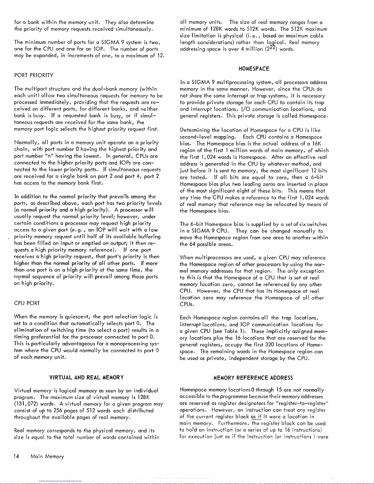
for a
bank
the
priority
The minimum
one
for
the
be
may
PORT PRIORITY
The
each
processed
ceived
bank
taneous
memory
Normally,
chain,
port
connected
nected
are
has
In
ports,
(a normal
usually
certain
access
_
priority
has
quests a high
rece
higher
than
nC?,rmal
on
CPU PORT
expanded,
multiport
unit)
on
is
busy.
requests
port
with
number
to
received
access
addition
as
request
conditions a processor
to a given
memory
been
ives a
than
one
sequence
high
priority.
within
of
memory
number
CPU
structure
allow
immed
iately,
different
If
are
logic
all
ports
port
"n"
to
the
the
lower
for a
to
the
to
the
described
priority
the
request
filled
on
priority
high
priority
the
normal
port
is
on a high
the
memory
of
and
one
in
increments
two
simultaneous
ports,
a
requested
received
selects
in a memory un it
number 0 having
having
higher
pr
iority
single
memory
normal
above,
and a high
normal
port
input
memory
of
priority
unit.
requests
ports for a
for
an
and
the
providing
for
different
bank
for
the
highest
the
lowest.
priority
ports.
bank
on
bank
priority
each
priority). A processor
priority
may
(e.
g.,
an
until
half
or
emptied
reference).
request,
priority
priority
will
They
received
SIGMA
lOP.
of
one,
dual-bank
requests
that
is busy,
the
same
priority
operate
the
highest
In
ports
and
If simul
port 2 and
fj rst.
that
prevails
port
has
level;
request
lOP
will
of
its
on
that
portis
of
all
other
at
the
prevail
also
determine
simultaneously.
9 system
The
number
to a maximum
memory
for memory
the
requests
banks,
output;
or
bank,
request
on a
priority
general,
lOPs
taneous
port
two
priority
however,
high
wait
available
If
priority
ports.
same
among
and
if siml!l-
the
CPUs
are
4,
among
priority
with a low
it
then
one
time,
those
is
two,
of
ports
of
(within
to
are
re-
neither
first.
priority
and
are
con-
requests
port
2
the
levels
will
under
buffering
re-
port
is
then
If
more
the
ports
12.
be
all
memory
minimum of 128K words to 512K words. The 512K maximum
size
length
addressing
units.
limitation
considerations)
space
The
is
physical
rather
is
over 4 million
size
(i.
of
e.,
than
real
based
memory
logical.
(222) words.
ranges
on maximum
Real memory
from a
cable
HOMESPACE
In a
SIGMA 9 multiprocessing
memory in
not
to
provide
and
general
Determining
second-level
bias.
region
the
address
i ust
are
Homespace
of
the
any
of
real
the
The
in a
move
the
When
the
mal memory
to
this is
memory
CPU.
location
CPUs.
the
share
the
same
private
interrupt
first
before
tested.
time
Homespace
6-bit
SIGMA
the
64
multiprocessors
Homespace
locations,
registers.
the
mapping.
The
Homespace
of
the
first 1
1,024
is
generated
it is
If
bias
most
significant
the
CPU makes a
memory
Homespace
9 CPU. They
Homespace
possible
addresses
that
location
However,
zero
the
may
same
storage
This
location
words is
sent
all
plus two
that
bias.
areas.
region
Homespace
zero,
the
manner.
interrupt
private
bias
million
in
the
to
memory,
bits
eight
reference
bias
region
are
of
for
cannot
CPU
reference
system,
However,
or
trap
for
each
I/O
communication
storage
of
Homespace
Each
CPU
is
the
actual
words
of
Homespace.
CPU
by
the
are
equal
leading
used, a given
other
that
of
these
reference
may
is
supplied
can
from
processors
region.
of
a CPU
be
that
has its
the
zeros
be
one
referenced
all
processors
since
systems,
CPU
contains a Homespace
main
After
whatever
most
to
bits.
to
be
changed
Homespace
it
to
contain
locations,
is
called
for a CPU is
address
memory,
an
si
gn i fi
zero,
are
inserted
This means
the
first
relocated
by a
set
area
to
CPU may
by
using
The
only
that
is
by
Homespace
address
the
CPUs do
is
necessary
its
Homespace.
like
of
a 16K
of
effective
method,
then a 6-bit
of
manually
another
cant
1,024
by
means of
six
switches
reference
the
exception
set
at
any
at
of
all
and
12
in
within
real
other
real
other
trap
and
which
real
bits
place
that
words
to
nor-
When
the
memory
set
to a condition
elimination
timing
preferential
This is
particularly
tem
where
the
of
each
memory un
Virtual
program.
(131,072)
consist
throughout
Real memory
size
14
memory is
of up
is
equal
Main
The maximum
words. A
is
that
of
switching
CPU would
it.
VIRTUAL
logical
to
256
the
avai
corresponds
to
the
Memory
quiescent,
automatically
time
(to
for
the
processor
advantageous
normally
AND
REAL
memory as
size
of
virtual
pages
lable
total
memory for a
of
512
pages
to
the
number
the
port
selection
selects
select a port)
connected
for a
monoprocessing
be
connected
MEMORY
seen
virtual
memory is 128K
words
each
of
real
memory.
physi
cal
memory,
of
words
port
by
given
contained
logic
O.
The
results
to
port
to
port
an
individual
program may
distributed
and
within
is
in a
O.
sys-
its
Each
Homespace
interrupt
a
ory
0
general
space.
be
Homespace
accessibl
are
operations.
of
main memory.
to
for
locations,
given
CPU (see
locations
registers,
The
used as pri
e to
reserved
the
current
hold
an
execution
region
contains
and
lOP
Table
1). These
plus
the
16
locations
occupy
remaining
vate,
MEMORY
memory 10cationsO through 15
the
as
register
However,
register
instruction
just as if
words in
independent
REFERENCE
programmer
designators
an
block
Furthermore,
(or c series
the
all
communication
implicitly
that
the
first
320
the
Homespace
storage
because
for
instruction
as if
it
were a location
the
register
of
instruction
the
ADDRESS
thei
can
up to 16
trap
locations,
locations
assigned
are
reserved
locations
by
the
are
not
r memory
"register-to-register
treat
block
instructions)
(or
instructions)
for
of
Homeregion
CPU.
normally
addresses
any
register
in
can
be
mem-
can
used
for
the
ll
were
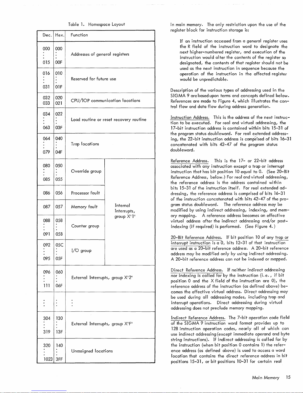
Dec.
Hex.
000
000
OOF
015
016
010
031 01F
032 020
033
021
022
034
063 03F
040
064
079
04F
Table 1. Homespace Layout
Function
Addresses
Reserved for future use
CPU/lOP
Load routine
T rap
of
general
communication
or
locations
reset
registers
recovery
locations
routine
in main memory. The
register
Description
SIGMA 9 are
References
trol flow and
Instruction Address. This is
tion
17-bit
the
ing,
concatenated
doubleword.
block
for instruction
If
an instruction
the
R field
next
higher-numbered
instruction would
designated,
used as
operation
would
to
program
the
the
be
unpredictable.
of
the
based upon terms and
are
data
be
executed.
instruction address is
status doubleword.
22-bit
with bits
only
accessed
of
the
instruction
alter
the
contents
next
instruction in
of
the
instruction in
various types
made to Figure
flow during address
For real and
instruction address is comPrised
42-47
restriction
storage
from a
word
register,
the
contents
of
that
sequence
of
addressing used in
concepts
4,
which illustrates
the
address of
virtual
contained
For real
of
the
upon
the
use
is:
general
and
register
the
generation.
register
to
designate
execution
of
the
register
should
because
affected
defined
the
next
addressing,
within bits 15-31
extended
of
program
status
of
the
uses
the
of
the
so
not
be
the
register
the
below.
the
con-
instruc-
the
of
address-
bits 16-31
080 050
085 055
086 056
057
087
058
088
091
05B
092
05C
095
05F
096 060
111
06F
Override
Processor fau
Memory fau
Counter group
I/O
External Interrupts, group X'2
group
group
I t
I t
Internal
Interrupts,
group
Reference Address. This is
associated
instruction
Reference Address,
the
bits 15-31
dressing,
of
the
gram status doubleword. The
modified by using
X
11
'
1
ory mapping. A
virtual
indexing
20-Bit
interrupt
are
address may
A
20-bit
Direct
nor
position 0 and
reference
comes
be
used during all addressing modes,
interrupt
addressing does
with
any
instruction
that
has
bit
below.)
reference
instruction
Reference Address.
used as a
indexing
the
address is
of
the
instruction
the
reference
concatenated
indirect
reference
address
Reference Address. If
after
the
(if required) is performed. (See Figure
instruction is a
20-bit
reference
be
modified
reference
address of the instruction (as
effective
operations.
address
is
called
the X field
virtual address.
not
preclude
the
except a trap
position 10
For real and
the
address
itself.
address
for by
Direct
is
with bits
reference
addressing,
address becomes
indirect
If
bit
0,
bits 12-31
address. A
only
by using
can
not be
neither
the
of
the
addressing during
memory mapping.
17-
or
22-bit
equal
to
O.
virtual
contai
For real
comprised of
42-47
address may
indexing,
addressing
position 10
of
that
20-bit
indirect
indexed
indirect
instruction
instruction
defined
Direct
addressing may
including
address
or
interrupt
(See
addressing,
ned
wi
thi n
extended
bits
16-31
of
the
and
an
effective
and/or
4.
)
of
any
instruction
reference
addressing.
or mapped.
addressing
(i.
e.,
if
are
0),
above)
trap
virtual
20-Bit
ad-
pro-
be
mem-
post-
trap
bit
the
be-
and
or
130
304
External
319 13F
320
140
Unassigned
1023
3FF
Interrupts, group
locations
XI
Indirect
F'
of
128
use
string instructions). If
the
ence
location
positions
Reference' Address. The
the
SIGMA 9 instruction word format provides up
instruction
indirect
instruction (when
address (as
addressing
that
contains
15-31,
operation
(except
indirect
bit
position 0
defined
the
or
bit
positions 10-31 for
7-bit
operation
codes,
nearly
all
immediate operand and
addressing
contains
above)
direct
is used
reference
to
Main
is
access
certain
code
of which
called
for by
1)
the
refer-
a word
address in
real
Memory
field
to
can
byte
bit
15
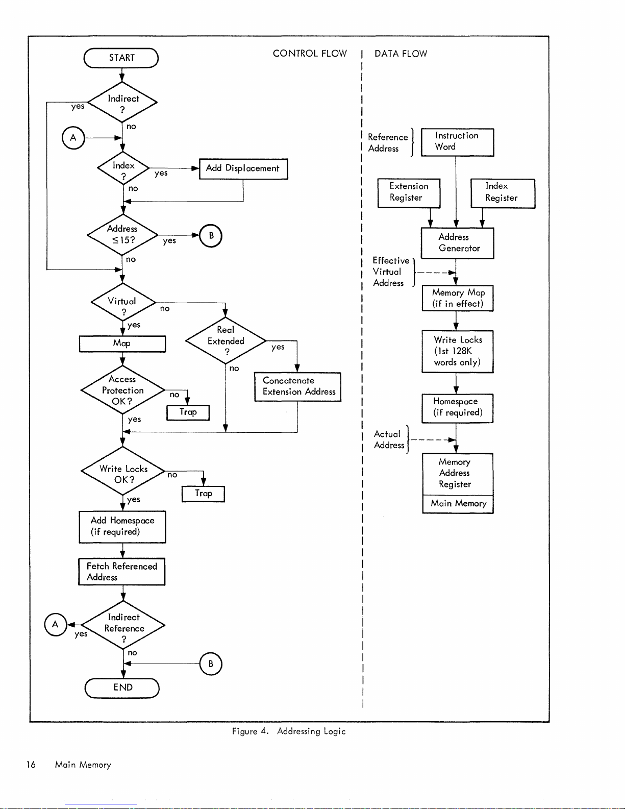
CONTROL
FLOW
DATA
FLOW
yes
Reference}
Address
Instruction
Word
Address
Write locks
(lst
128K
words only)
Add
Homespace
(if required)
B
Figure 4. Addressing Logic
Actual}
Address - - - -
r----'-----.
Memory
Address
Register
Main Memory
16
Main Memory
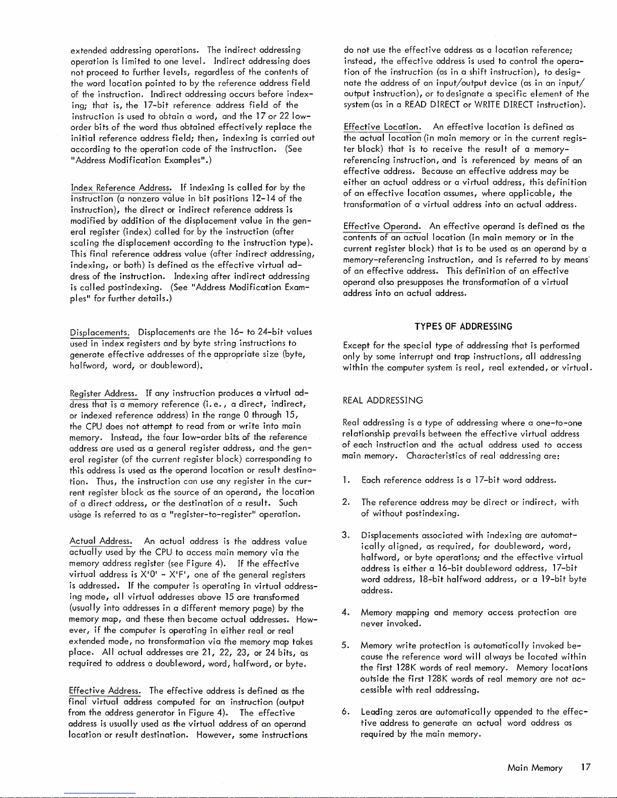
extended
operation
not
the
of
ing;
instruction
order
initial
according
II
Address
proceed
word
the
instruction.
that
bits
reference
addressing
is
I imited to
to
further
location
pointed
Indirect
is,
the
17-bit
is
used
to
of
the
word thus
address
to
the
operation
Modification
operations.
levels,
obtain
Index Reference Address.
instruction
instruction),
modified by
eral
scaling
This final
indexing,
dress of
called
is
ll
ples
(a
register
the
displacement
reference
or
the
postindexing.
for
further
nonzero
the
direct
addition
(index)
of
called
address
both)
is
defined
instruction.
details.)
value
The
one
level.
regardless
to by
the
addressing
reference
a word, and
obtained
field;
then,
code
of
Examples
or
the
ll
.)
If
i ndexi ng is
in
bit
indirect
displacement
for by
according
value
as
the
Indexing
(See IIAddress
indirect
Indirect
of
reference
occurs
address
effectively
indexing
the
instruction.
ca
positions
reference
the
instruction
to
the
(after
indirect
effective
after
indirect
Modification
addressing
addressing does
the
contents
address
before
field
of
the
the
17
or
22
replace
is
carried
(See
II
ed
for by
12-14
of
address is
value
in
the
(after
instruction
addressing,
virtual
addressing
Exam-
of
field
index-
low-
the
out
the
the
gen-
type).
ad-
do
not
use
the
effective
instead,
tion
nate
output
system (as in a
Effective
the
ter
referencing
effective
either
of
transformation
Effective
contents
current
the
of
the
the
address of
instruction),
Location.
actual
location
block)
that
address. Because
an
actual
an
effective
Operand.
of
register
effective
instruction
READ
is to
instruction,
address
location
of a virtual
an
actual
block)
memory-referencing
of
an
effective
operand
address
into
also
presupposes
an
address. This
actual
address as a
address is used
(as in a
an
input/output
or to
designate a specific
DIRECT
An
or
effective
shift
device
WRITE
location
location
to
instruction),
DIRECT
(in main memory or in
receive
An
location
that
instruction,
the
result
and
is
referenced
an
effective
or a virtual
assumes,
address
effective
address,
where
into
operand
(in main memory or in
is
to
be
used as
and
is
an
definition
the
transformation
address.
reference;
control
the
to
(as in
an
element
instruction).
is
defined
the
current
of
a memory-
by
means of
address may
this
applicable,
actual
address.
is
defined
an
operand
referred
of
an
effective
to
of a virtual
opera-
desig-
input/
of
the
as
regis-
an
be
definition
the
as
the
the
by
by means-
a
Displacements. Displacements
used in
generate
halfword, word,
Register Address. If
dress
or
the
memory.
address
eral
this address is used as
tion.
rent
of a direct
usage is
Actual
actually
memory address
virtual
is
ing
(usually
memory
ever,
extended
place.
required
Effective Address. The
final
from
address
location
index
registers and
effective
that
is a memory
indexed
CPU
reference
does
not
Instead,
are
used
as a general
register
register
Thus,
(of
the
the
instruction
block
address,
referred
to as a
Address.
used by
register
address
addressed.
mode,
if
If
all
virtual
into
addresses in a
map,
and
the
computer
is
the
mode, no transformation
All
actual
to address a
virtual
the
address computed for
address
is
or
generator
usually
result
addresses
or
doubleword).
any
instruction
reference
address) in
attempt
the
to
four
current
the
operand
as
the
source
or
the
destination
II
reg
An
actual
the
CPU to
(see
XIQI
- XIFI,
computer
addresses
these
then
is
operating
addresses
doubleword,
effective
in Figure
used
as
the
destination.
by
low-order
register
can
different
are
the
16-
byte
string
of
th e
appropriate
produces a virtual
(i.
e., a direct,
the
range
read
from or
h
its-
register
address,
block)
location
use
any
register
of
an
operand,
of a result.
ister-to-register
address
access
Figure
is
main memory
4). If
one
of
operating
above
is
the
15
the
are
memory
become
are
actual
in
either
via
the
21, 22,
word,
23,
halfword,
address is
an
instruction
4).
virtual
address
However,
to
24-bit
values
instructions
size
to
(byte,
ad-
indirect,
Q through
write
of
the
into
reference
and
the
15,
main
gen-
corresponding
or
result
destina-
in
the
cur-
the
location
Such
ll
operation.
address
the
general
in
via
effective
registers
virtual
value
the
addresstransformed
page)
by
the
addresses. How-
real
or
real
memory map
or
defined
24
bits,
or
as
takes
as
byte.
the
(output
The
effective
of
an
opercmd
some instructions
to
TYPES
Except for
only
within
REAL
Real addressing
relationship
of
each
main memory.
1. Each
2.
3.
4.
5.
6.
the
by some
the
computer
special
interrupt
type
and
system
ADDRESSING
is a type
prevails
instruction
between
and
Characteristics
reference
The
reference
of
without
Displacements
ically
aligned,
halfword,
address
word
is
address,
address is a
address may
postindexing.
associated
as
required,
or
byte
operations;
either a 16-bit
18-bit
address.
Memory mapping and memory
never
invoked.
Memory
cause
the
outside
cessible
Leading
tive
required
write
protection
the
reference
first 128K words
the
first 128K words
with real addressing.
zeros
are
automatically
address
by
to
the
generate
main memory.
OF
ADDRESSING
of
trap
is
of
addressing
the
actual
addressing
instructions,
real,
the
effective
of
real addressing
17-bit
be
with
for
that
real
extended,
where a one-to-one
address used to
word address.
direct
or
indexing
doubleword,
and
the
doubleword
halfword
address,
access
is
automatically
word will
of
always
real memory. Memory
of
real memory
appended
an
actual
word address as
is performed
all
addressing
virtual
are:
indirect,
are
automat-
effective
address,
or a 19-bit
protection
invoked
be
located
are
to
or
virtual.
address
access
with
word,
virtual
17-bit
byte
are
be-
within
locations
not
ac-
the
effec-
Main
Memory
17
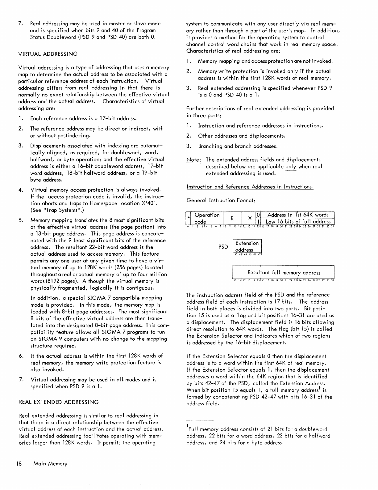
7.
Real
addressing
and
is
specified
Status
Doubleword
VIRTUAL ADDRESSING
Virtual
map
particular
addressing
normally
address
addressing
1. Each
2.
3.
4.
5.
6.
7.
addressing
to
determine
reference
differs
no
exact
and
the
are:
reference
The
reference
or
without
Displacements
ically
aligned,
halfword,
address
word
byte
Virtual
If
tion
(See
Memory mapping
of
a
nated
address.
actual
permits
tual
throughout
words (8192
physically
In
mode
loaded
8
lated
patibility
on
structure
If
real
also
Virtual
specified
REAL
is
address,
address.
memory
the
access
aborts
"Trap
the
effective
13-bit
with
address
anyone
memory
addition, a special
is
with
bits
of
into
SIGMA 9 computers
the
actual
memory,
invoked.
addressing
EXTENDED ADDRESSING
may
when
is a type
the
actual
address
from
relationship
actual
address is a
address may
postindexing.
associated
as
or
byte
either a 16-bit
l8-bit
access
protection
and
traps
Systems".)
virtual
page
address. This
the 9 least
The
resultant
used
user
of
up
a real
or
pages).
fragmented,
provided.
8-bit
the
effective
the
designated
feature
required.
address
the
when
PSD
be
used
in
master or
bits 9 and
(PSD 9
and
PSD
of
addressing
address to
of
each
real
addressing
between
address.
required,
operation;
to
translates
to
at
to
actual
Although
In
page
allows
memory
may
9 is a 1.
Characteristics
17-bit
be
direct
with
indexing
for
and
doubleword
halfword
protection
significant
access
128K words (256
SIGMA 7 compatible
this
virtual
is
address,
code
is
Homespace
the
8 most
address
22-bit
any
logically
addresses.
with
within
be
(the
page
word address
memory. This
given
memory
the
mode,
address
8-bit
page
all
SIGMA
no
the
write
used in
slave
40
of
the
Program
40)
are
both
that
uses a memory
be
associated
instruction.
in
the
address.
or
doubleword,
the
effective
address,
is
always
inval
id,
location
page
address
bits
of
time
of
up
virtual
it
is
contiguous.
the
memory map is
The most
are
address.
7 programs to run
change
first 128K words of
protection
all
modes
Virtual
that
there
effective
of
indirect,
are
automat-
word,
or a 19-bit
invoked.
the
instruc-
X'40'.
significant
portion)
is
concqte-
the
reference
is
the
feature
to
have a vir-
pages)
located
to
four
memory
mapping
significant
then
This
to
the
mapping
feature
and
mode
O.
with
is
virtual
virtual
with
virtual
l7-bit
bits
into
million
is
trans-
com-
is
is
system to
ory
it
channel
Characteristics
1.
a
2.
3.
Further
in
1.
2.
3.
Note:
Instruction
General
The
address
field
tion
displacement.
a
direct
the
is
If
address
If
addresses a word
by bits
When
formed by
address
communicate
rather
than
through a
provides
three
addressed
the
the
a method for
control word
of
Memory mapping
Memory
address
Real
is
Instruction
Other
Branching
instruction
15
Extension
write
is
extended
a 0
and
descriptions
parts:
addresses
The
extended
described
extended
and
Instruction
PSD
field
of
in
both
places
is
used
resolution
by
Extension
is
to a word
Extension
42-47
bit
position
concatenating
field.
within
PSD
and
address
as a flag
Selector
of
with
part
the
chains
real
addressing
and
access
protection
the
first 128K words
addressing
40
is
a 1.
of
real
and
reference
and
displacements.
branch
address
below
are
addressing
Reference
each
The
to
the
Selector
Selector
within
the
15
Addresses
Format:
field
instruction
is
divided
and
displacement
64K words. The
and
16-bit
equals 0 then
within
equals
the
PSD,
equals
PSD
any
user
directly
of
the
user's
map.
operating
that
is
is
extended
addresses in
addresses.
fields
appl
is
used.
of
bit
indicates
displacement.
the
64K
call
ed
1,
42-47
system
work in
are:
protection
invoked
specified
icable
the
is
into
positions 16-31
first 64K
1,
region
the
a full memory addresst is
real
are
only
of
whenever
addressing is
instructions.
and
displacements
only
--
in
Instructions.
PSD
and
17
bits.
two
parts.
field
is 16
flag
(bit
which
of
the
displacement
of
real
then
the
that
Extension Address.
with
bit"s
via
real
mem-
In
addition,
to
control
memory
not
if
real memory.
when real
the
The address
bits
15)
two regions
displacement
is
identified
16-31
invoked.
the
actual
PSD
provided
reference
Bit
posi-
are
used as
allowing
is
called
memory.
of
space.
9
the
Real
extended
that
there
virtual
extended
Real
ories
larger
18
Main
is a direct
address
than
Memory
addressing is
of
each
addressing
128K words. It permits
similar
relationship
instruction
faci I itates
between
to
real
and
the
operating
addressing in
the
actual
the
effective
address.
wi
th
mem-
operating
t
memory address consists
Ful1
address,
address,
22
bits
and 24 bits for a
for a word
of
address,
byte
address.
21
bits for a
23 bits for a halfword
doubleword
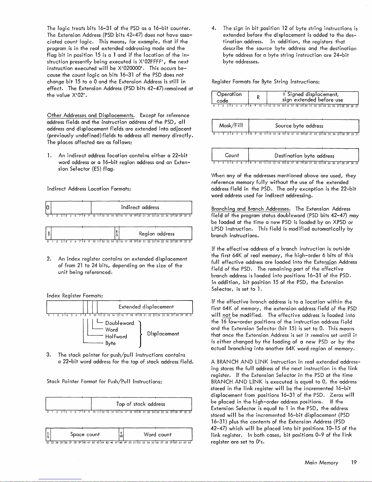
The
logic
treats
bits
The Extension Address
ciated
count
logic.
program
flag
struction
instruction
cause
change
effect.
the
Other
address
address and
(previously
The
is
in
the
real
bit
in position 15 is a 1 and if
presently
executed
the
count
bit
15 to a 0
The Extension Address
value
X'021.
Addresses
fields
places
affected
being
logic
and
and
the
displacement
undefined)
16-31 of
This means, for
extended
will
on bits 16-31
and
Displacements.
instruction address
fields
are
the
(PSD
bits
addressing mode and
executed
be
X'020000'. This
the
Extension Address
(PSD
fields
are
to
address
as follows:
PSD
42-47)
as a
does not
example,
the
location
is
X'02FFFF',
of
the
bits
42-47)
Except for
of
extended
all
memory
16-bit
occurs
PSD
the
into
counter.
have
that
if
the
of
the
the
next
be-
does
not
is
still
remained
reference
PSD,
all
adjacent
directly.
asso-
the
in-
in
at
4.
The sign in
extended
tination
describe
byte
byte
Register Formats for Byte String Instructions:
bit
position
before
address.
the
source
address for a
addresses.
12 of
the
displacement
In
addition,
byte
byte
stri ng
byte
the
address
instruction
string
is
added
registers
and
instructions
to
the
that
the
destination
are
24-b
is
des-
it
1. An
Indirect
2.
Index Register Formats:
3.
Stack
indirect
word address or a
sion
Selector
Address Location Formats:
An
index
of from
unit
being
The
stack
a
22-bit
Pointer Format for Push/Pull Instructions:
address
register
21
to
referenced.
~
pointer
word address for
location
16-bit
(ES)
flag.
contains
24
bits,
~
Doubleword }
Word
Halfword DIsplacement
Byte
for
region address and
an
depending
push/pull
the
contains
extended
on
instructions
top
of
either a 22-bit
an
displacement
the
size
of
•
contains
stack
address
Exten-
the
field.
When
any
of
the
addresses
reference
address
word address used for
Branching and Branch Addresses. The Extension Address
field
be
LPSD
branch
If
the
the
full
field
branch
In
addition,
Sel
the
If
first 64K of memory,
will
the
and
that
is
either
actual
A BRANCH
ing stores
register.
BRANCH
stored in
displacement
be
Extension
stored
16-31)
42-47)
I ink
register
memory
field
of
the
loaded
at
instruction.
instructions.
effective
first 64K of real memory,
effective
of
the
address
ector,
is
effective
not
be
f6low-order
the
Extension
once
the
changed
branching
the
If
AND
the
placed
in
Selector
will
plus
which will
register.
are
fully
in
the
program
the
time a new
This
address
address
PSD. The remaining
is
loaded
bit
position
set
to
1.
branch
modified. The
positions of
Selector
Extension Address
by
into
AND
LINK instruction in real
full address of
the
Extension
LINK
link
register
from positions 16-31 of
the
high-order
is
be
the
incremented
the
contents
be
In
both
set
to
OIS.
mentioned
without
PSD. The
indirect
status
doubleword
field
of a branch
are
loaded
into
15 of
address
the
extension
effective
(bit
the
loading
another
Selector
is
executed
will
address positions.
equal
to 1
of
the
placed
cases,
above
are
the
use
of
the
extended
only
exception
addressing.
(PSD
PSD
is
loaded
is
modified
instruction
the
high-order
into
the
part
of
positions 16-31
the
PSD,
is
to a
location
address
address
the
instruction
15)
is
set
is
set
it
of a new
64K word
the
next
instruction in
in
the
is
equal
be
the
incremented
the
in
the
PSD,
16-bit
displacement
Extension Address (PSD
into
bit
positions
bit
positions
is
bits
by
an
automatically
6 bits of this
ExtelltiQJJ Address
the
effective
of
the
Extension
field
is
address
to
O.
remains
PSD
region
extended
PSD
at
to
0,
PSD.
the
10-15
0-9
of
used,
the
22-bit
42-47)
XPSD or
is
outside
the
PSD.
within
the
of
the
loaded
field
This means
set
until
or by
of memory.
address-
the
the
time
the
address
16-bit
Zeros
will
If
the
address
(PSD
of
the
I ink
they
may
by
PSD
into
it
the
link
the
Main
Memory 19
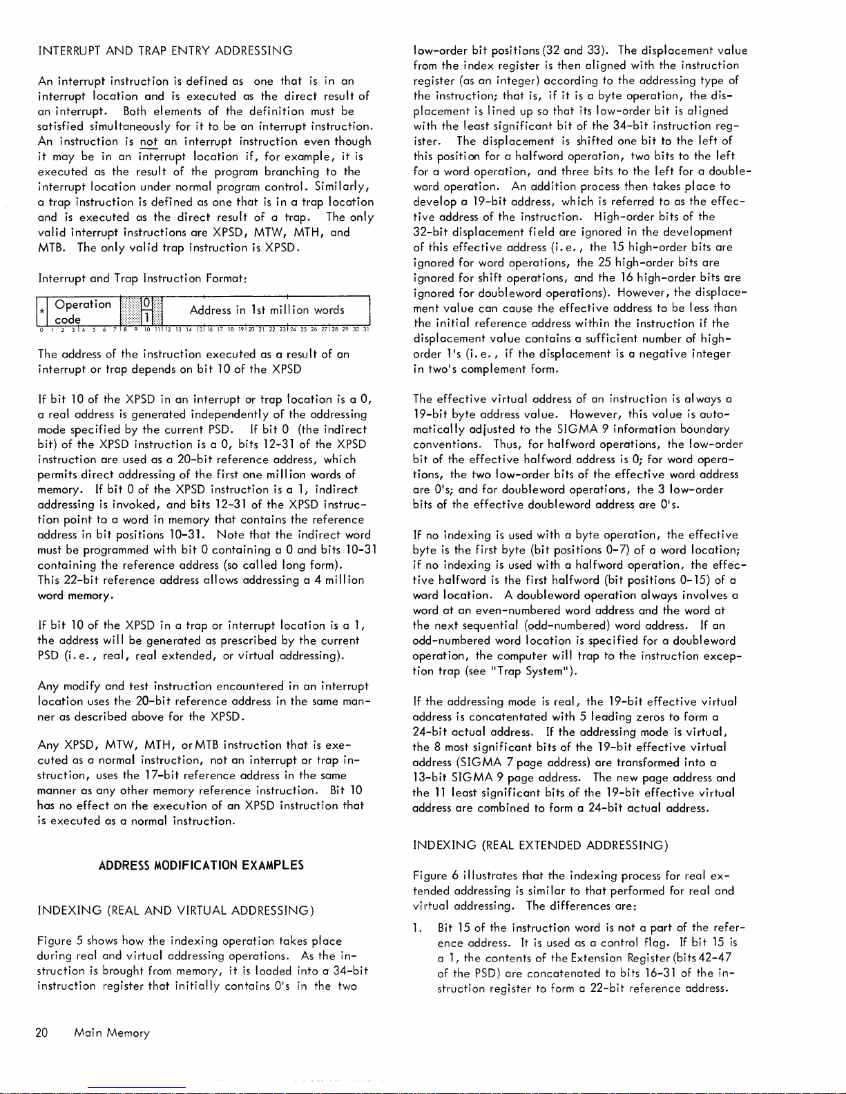
INTERRUPT
interrupt
An
interrupt
an
interrupt.
satisfied
An
instruction
it
may
executed
interrupt
a
trap
and
valid
MTB.
Interrupt
The address of
interrupt
If
bit
a
real
mode
bit)
of
instruction
permits
memory.
addressing
tion
point
address in
must
containing
This
AND
instruction
location
Both
simultaneously
is
be
in
an
as
the
location
instruction
is
executed
interrupt
The
instructions
only
valid
and
Trap Instructi on Format:
the
or
trap
10
of
the
XPSD
address
specified
the
be
22-bit
is
by
XPSD
are
used as a
direct
addressing
If
bit 0 of
is
invoked,
to
a word in memory
bit
positions
programmed with
the
reference
reference
TRAP
ENTRY
is
and
is
elements
for
not
an
interrupt
result
of
under
normal program
is
defined
as
the
direct
trap
instruction
depends
in
an
generated
the
current
instruction
20-bit
the
XPSD
and
10-31.
address
defined
executed
of
it
to
interrupt
location
the
as
are
instruction
executed
on
bit
interrupt
independently
PSD.
is a
of
the
bits
bit 0 containing
address (so
allows
word memory.
If
bit
10
of
the
XPSD
in a
trap
the
address will
PSD
(i.
e.,
Any modify
location
ner
as
described
uses
real,
and
the
be
generated
real
test
instruction
20-bit
above
as
extended,
reference
for the XPSD.
Any XPSD, MTW, MTH, orMTB
cuted
as a normal
struction,
manner
has no
effect
is
executed
as
uses
any
instruction,
the
17-bit
other
memory
on
the
execution
as a normal
reference
reference
instruction.
ADDRESSING
as
one
that
is
as
the
direct
the
definition
be
an
interrupt
instruction
if,
program
even
for
example,
branching
control.
one
that
is
in a
trap
result
of a trap.
XPSD, MTW, MTH,
is XPSD.
as a
result
10
of
the
XPSD
or
trap
location
of
the
addressing
If
bit 0 (the
0,
bits 12-31
reference
first
one
instruction
12-31
of
that
contains
Note
that
called
addressing
or
interrupt
prescribed
or
virtual
encountered
address in
instruction
not
an
interrupt
address
of
address,
mi
II
ion words of
is
a 1,
the
XPSD
the
the
indirect
a 0
and
long form).
a 4 mill ion
location
by
the
addressing).
in
an
the
that
or
in
the
instruction.
of
an
XPSD
instruction
in
an
result
of
must
be
instruction.
though
it
is
to
the
Similarly,
location
The
only
and
of
an
is a 0,
indirect
the
XPSD
which
indirect
instruc-
reference
word
bits
10-31
is a 1,
current
interrupt
same
man-
is
exe-
trap
in-
same
Bit
10
that
low-order
from
register
the
placement
with
ister. The
this positi
for a word
word
bit
the
index
(as
an
instruction;
is I
the
least
displacement
on
for a
operation,
operation.
positions
register
integer)
that
ined
significant
develop a 19-bit
tive
address
32-bit
of
this
ignored
ignored
ignored
ment val
the
initial
displacement
order
in
two's
The
effective
19-bit
matically
conventions.
bit
of
tions,
are
O'S;
bits of
If
no
byte
if
no
tive
halfword
word
word
the
next
odd-numbered
operation,
tion
trap
If
the
address is
24-bit
the
8 most
address
13-bit
the
11
address
of
the
displacement
effective
address (i.
for word
for
shift
operations,
for
doubleword
ue
can
cause
reference
value
lis
(i.
e.,
if
complement
virtual
byte
address
adjusted
Thus, for
the
effective
the
two
low-order
and
for
doubleword
the
effective
indexing
is
indexing
the
first
is
is
is
byte
the
location. A doubleword
at
an
even-numbered
sequential
word
the
computer
(see
liT
rap System
addressing mode
concatentated
actual
address.
significant
(SIGMA 7 page
SIGMA 9 page
least
significant
are
combined
(32
and
33). The
is
then
aligned
according
is, if
it
is a byte
up so
that
its
bit
of
the
is
shifted
halfword
An
address,
and
three
addition
which
operation,
bits
process
instruction.
fi
eld
are
ignored
e.,
the
operations,
the
and
operations).
the
effective
address
within
contains a sufficient
the
displacement
form.
address of
value.
to
the
an
However,
SIGMA 9 information
halfword
halfword
bits
address
of
the
operations,
doubleword
used
with a byte
(bit
positions
used
with
a halfword
first halfword
operation
word address
(odd-numbered)
location
is
If
bits
will
II
).
real,
with 5
the
of
is
specified
trap
the
leading
addressing
the
address)
address. The new
bits
.of
the
to
form a
24-bit
displacement
with
to
the
addressing
operation,
low-order
34-bit
one
bit
two
to
the
then
is
referred
High-order
in
the
15
high-order
25
high-order
the
16
high-order
However,
address
the
instruction
number of
is a
negative
instruction
this
operations,
is
0; for word
effective
the 3 low-order
address
are
operation,
0-7)
of
operation,
(bit
positions
always
and
word address.
for a
to
the
instruction
19-bit
zeros
mode
19-bit
effective
are
transformed
page
19-bit
effective
actual
the
instruction
the
bit
is
al
instruction
to
the
bits
to
left
for a
takes
place
to
as
the
bits
of
development
bits
bits
the
to
be
I ess
integer
is
always
value
is
boundary
the
low-order
word address
O's.
the
effective
a word
location;
the
0-15)
involves
the
word
doubleword
effective
to
form a
is
virtual,
virtual
into
address
address.
value
type
dis-
igned
reg-
left
of
the
left
double-
to
effec-
the
are
are
bits
are
displace-
than
if
the
high-
a
auto-
opera-
effec-
of a
at
If
an
excep-
virtual
a
and
virtual
of
a
ADDRESS
INDEXING
(REAL
Figure 5 shows how
during
real
and
struction
instruction
is
brought
register
MODIFICATION
AND
the
indexing
virtual
addressing
from memory,
that
initially
EXAMPLES
VIRTUAL ADDRESSING)
operation
takes
operations.
it
is
loaded
contains
O's
20 Mai n Memory
place
As
the
into a
in
the
in-
34-bit
two
INDEXING
Figure 6
tended
virtual
illustrates
addressing
addressing.
1. Bit 15
ence
a 1 r
the
of
the
struction
(REAL
of
the
address.
contents
PSD)
register
EXTENDED ADDRESSING)
that
the
is
simi
The
instruction
It
is
of
are
concatenated
to form a
indexing
lar
to
differences
word
used as a control
the
Extension Register (bits
process for
that
performed for real
are:
is
not a part
to bits 16-31 of
22-bit
reference
flag.
real
of
the
If
bit
42-47
the
address.
ex-
and
refer-
15
in-
is
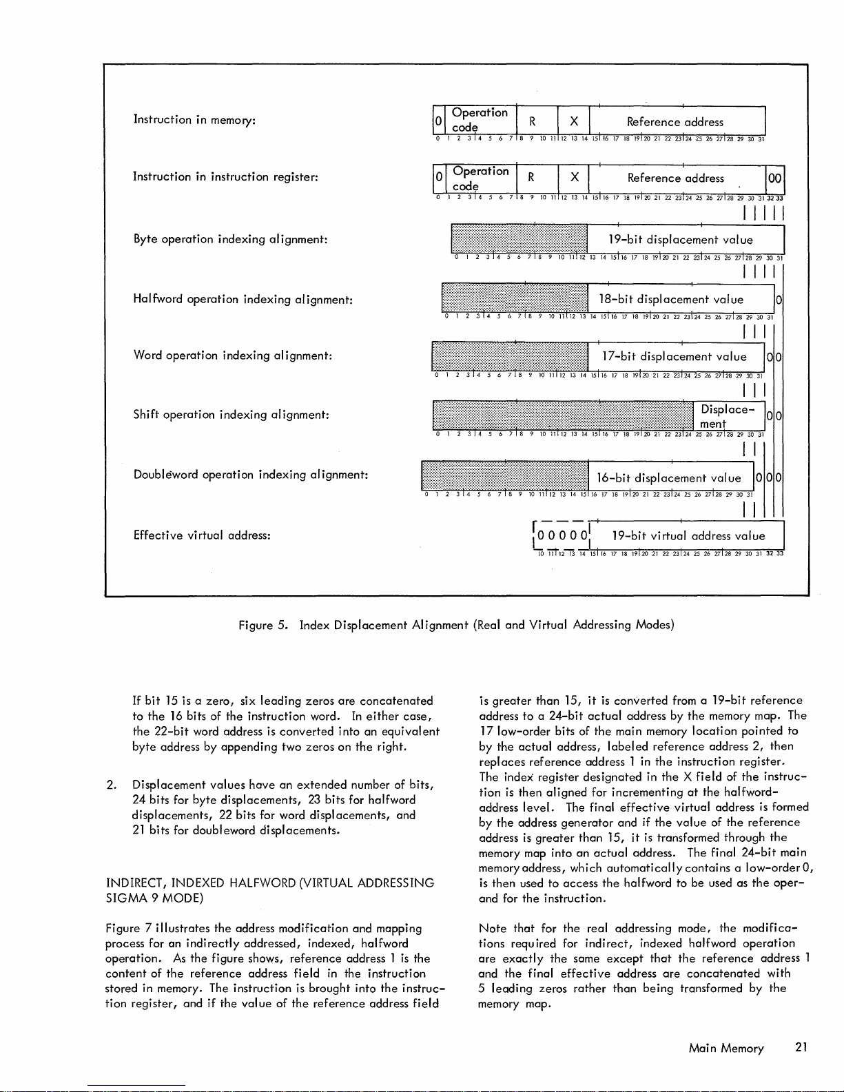
Instruction in memory:
Instruction
Byte
operation
Halfword
Word
Shift
Doubleword
Effective
operation
operation
operation
virtual address:
in
instruction
indexing
indexing
indexing
operation
register:
alignment:
indexing
alignment:
alignment:
indexing
al ignment:
alignment:
I
IIII
5.
Index
Figure
If
bit
15 is a
zero,
six
leading
to
the
16 bits of
the
22-bit
byte
address
2.
Displacement
24
bits for
displacements,
21
bits for doubleword
INDIRECT, INDEXED HALFWORD (VIRTUAL ADDRESSING
SIGMA
Figure 7
process for
operation.
content
stored in memory. The
tion
9 MODE)
illustrates
of
the
register,
an
As
and
the
instruction
word address is
by
appending
values
have
byte
displacements,
22 bits for word
the
address
indirectly
the
reference
figure
if
the
addressed,
shows,
address
instruction
value
converted
two
an
displacements.
modification
reference
of
the
Displacement
zeros
are
word.
into
zeros
on
extended
23
bits
displacements,
indexed,
address 1
field
in
the
is brought
reference
concatenated
In
either
an
the
number of
for halfword
and
halfword
instruction
into
address
AI
case,
equival
right.
bits,
and
mapping
is
the
the
instruc-
field
ent
ignment
(Real
and
Virtual Addressing Modes)
is
greater
address
17
by
replaces
The
tion
address
by
address
memory map into
memoryaddress,
is
then
and for
Note
tions requ ired for
are
and
leading
5
memory map.
than
to a 24-bit
low-order
the
actual
reference
index
register
is
then
level.
the
address
is
greater
used
the
that
exactly
the
final
zeros
bits of
address,
aligned
to
instruction.
for
the
15,
it
actual
the
address 1 in
designated
for
The final
generator
than
an
actual
which
access
the
real
indirect,
same
effective
rather
is
converted
address by
main memory
labeled
incrementing
effective
and
15,
it
automatically
the
halfword to be used
addressing mode,
except
address
than
from a
reference
the
instruction
in
the X field
virtual
if
the
value
is transformed through
address. The final
indexed
that
the
are
being
19-bit
reference
the
memory map. The
location
at
contains a 10w-orderO,
halfword
concatenated
transformed
pointed
address
the
of
reference
2,
then
register.
of
the
instruc-
halfword-
address is formed
the
reference
the
24-bit
as
the
oper-
the
modifica-
operation
address 1
with
by
the
to
main
Main Memory
21
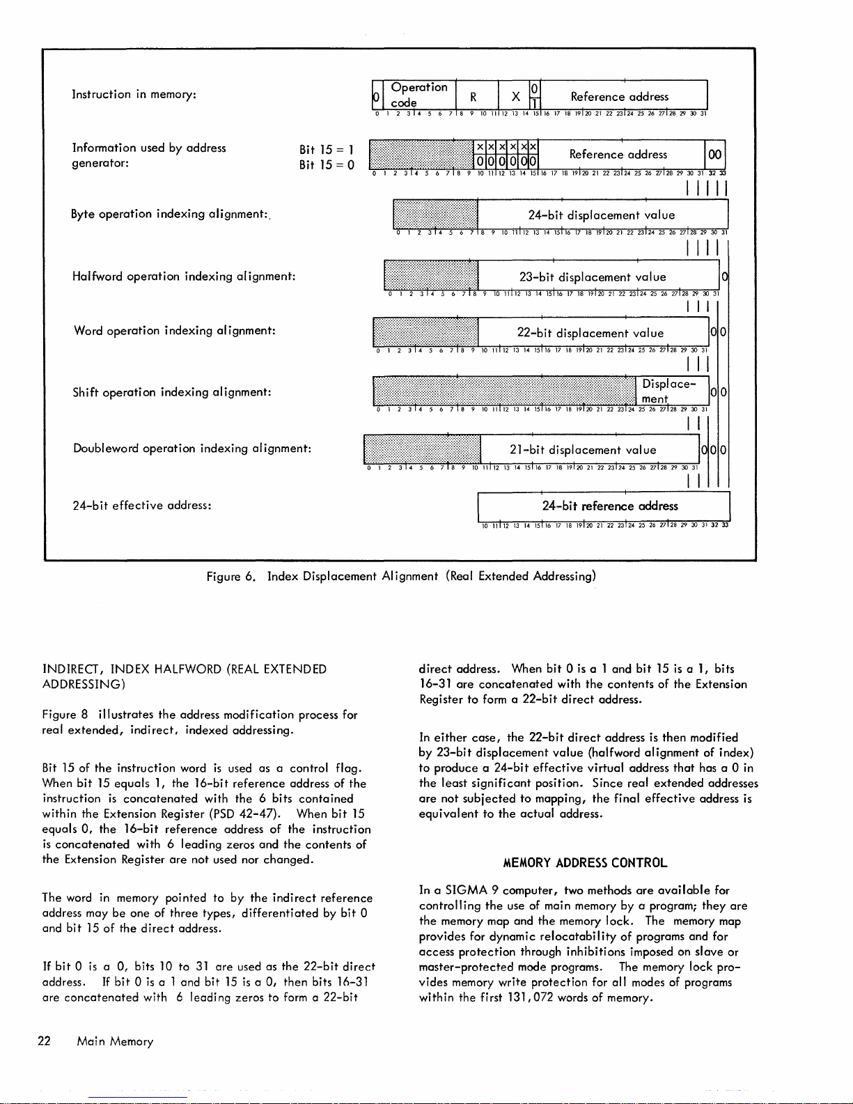
Instruction
in
memory:
Information used by address
generator:
Byte
operation
Halfword
Word
operation
Shift
operation
Doubleword
24-bit
effective
indexing
operation
operation
indexing alignment:
indexing alignment:
indexing alignment:
address:
alignment:.
indexing alignment:
Bit 15
Bit 15
= 1
= 0
24-bi~
displacement
;alue
I
IIII
I I
INDIRECT, INDEX
ADDRESSING)
Figure 8
real
Bit
When
instruction
within the Extension Register
equals
is
concatenated
the
The word in memory pointed
address may
and
If
bit 0 is a 0,
address.
are
illustrates
extended,
15 of
the
bit
15
is
0,
the
Extension Register
be
bi t 15
of
If
concatenated
HALFWORD
the
address modification process for
indirect,
instruction word
equals
concatenated
16-bit
with 6 leading zeros and
one of
the
direct
bits 10 to
bit 0 is
indexed addressing.
1, the
16-bit
reference
are
not used nor
three
address.
31
a 1 and bit
with 6 leading zeros to
Figure
6.
Index Displacement Alignment (Real Extended Addressing)
(REAL
EXTENDED
is
used as a control
reference
with
the
6 bits
(PSD
42-47).
address
changed.
to
by
the
types,
differentiated
are
used as the
15
is
a 0, then bits 16-31
address of
contained
When
of
the
instruction
the
contents
indirect
reference
22-bit
form a 22-bit
by
flag.
bit
bit
direct
the
15
of
direct
address. When
are
23-bit
least
not
concatenated
to
form a
case,
displacement
significant
subjected
to
the
16-31
Register
In
either
by
to
produce a 24-bit
the
are
equivalent
MEMORY
In a
SIGMA 9 computer,
0
controlling
the
memory map and
provides for dynamic
access
master-protected
vides memory write
within the first 131,
the
protection
bit 0 is
22-bit
the
22-bit
effective
position. Since real
to
mapping,
actual
use of main memory by a program;
the
relocatability
through inhibitions imposed on
mode programs. The memory lock
protection
072 words of memory.
a 1
and
bit
with
the
contents
direct
address.
direct
address is
value
(halfword
virtual address
the
final
address.
ADDRESS
two methods
memory
CONTROL
are
lock.
of
programs and for
for all modes of programs
15
is
a 1, bits
of
the
then
alignment
that
extended
effective
available
The memory map
Extension
modified
of index)
has a 0
addresses
address is
for
they
slave
or
pro-
in
are
22 Mai n Memory

Instruction in memory:
Instruction in instruction registers:
8-high-order
The
replaced
Actual address
the
17-bit
Indirect
with
Halfword
Effective virtual address:
with
direct
address:
direct
addressing replaces
direct
operation
bits of
13-bit
page
of
memory
address in memory:
address:
indexing alignment:
the
reference
address Z
location
reference
address
from
that
address
are
memory map:
contains
~--------~~--------~'r~------~~------~
24-bit
actual
address
III
III
The 8
high-order
replaced
Final memory address, which is
halfword
with
location
bits
13-bit
containing
Figure 7.
of
the
page
address N from memory map:
Generation
effective
the
the
effective
address
actual
of
are
address
halfword:
Actual Memory Addresses, Virtual Addressing (SIGMA 9 Mode)
of
,-------~~------~'r,-------~~--------
Main
Memory 23

Initial
conditions:
PSD
Ie
e e e e e\
42 43
44
45 46
.(
7
Instruction
rect
Indi
Contents
in
reference
of
indirect
Address used if
Address used
if
Address used if
instruction
addresses:
reference
bit
0 = 0:
bit
0 = 1
bit
0 = 1
register:
and
bit
and
bit
address:
15 = 0:
15 = 1:
If
If
bit
bit
15 = 1
15
= 0
\ e e e e e
10
11112
13
e:
r r r r r r r
14
1516
17
~
r r r r r r r
18
19120
2122
23 24
25
26
27128
29 30
\00
31
Displacement
Final
effective
aligned
address:
Figure 8.
for halfword
Generation
indexing:
24 Main Memory
of
Effective
Virtual
Address, Real Extended Addressing

MEMORY
The SIGMA 9 memory map
registers,
the
and
a speci
The memory
virtual
Memory
Virtual
addresses
X'1O'-X'1
(virtual
The most
sidered to be
ory
of
that
order
When SIGMA 9
mode,
This
the
load
instruction,
into
of
each
to
zero.
some address in
compatible
Associated with
256
of
these
specific
protection
of
the
The
MAP
AND ACCESS PROTECTION
is
physically
each
containing
CPUls fast memory. Each
contains a 13-bit
fi c 512-word
page
address codes
13
bits. The
register
actual
memory
page
of vi rtua I addresses.
are
addresses as follows:
page
(13 bits
8-bit
X
Memory
Virtual
page
(13 bits)
8-bit
K
addresses addresses
FF'
page
significant
the
reference,
an
element
element
9 bits
is
are
of
the
map
accompl ished by
0)
virtual
the
virtual
of
the
then
the
17-bit
is
operating
appears
X'200'-X
(virtual
8 bits
map. The 13 bits
3FF'
'
page
1)
of a 17-bit
page
number. Just prior
page
number
used in
conjunction
virtual address.
in
the
identical
retaining
to
the
MOVE TO MEMORY CONTROL (MMC)
the
map in a
the
map. The 8 bits
map
This means
8-bit
quantities
element
the
compatible
manner.
from memory
are
stored
and
the
upper 5 bit
that
the
map will
first 128K of real memory, which is
for SIGMA 7 programs.
the
2-bit
registers, also
registers
512-word
code
corresponding
access
control codes
memory map
located
contains a 2-bit
page
of virtual addresses. The
indicates
page
are
feature
in
access
the
allowed
of
virtual memory.
assigned as follows:
an
array
of
array
is
stored in
has
an
8-bit
address
page
address
code
assigned to pages
Memory
page
(13 bits)
Virtual
XI
(vi rtual
8-bit
1 FEOO'-X' 1 FFFF'
page
virtual address
to
is
used as
an
contained
with
the
SIGMA
7-compatible
the
SIGMA 7 map.
SIGMA 7 version
instruction
In
this form
are
transmitted
in
the
low-order
positions
always
is
another
CPU
fast memory. Each
control
use or
are
relocate
code
availability
256
for
of
255)
is
a memaddress
within
low-
of
of
the
8 bits
set
to
series
for a
access
N
con-
to
of
Access
in
slave
(PSD
protection
effect
mode
40 = 1). Access
computer
When
the
used by
whether
the
direct,
(PSD
is
memory map
is
9 =
1)
(PSD
8 =
operating
program
indirect,
in
effect
and
the
1)
or
in
protection
in
the
master mode.
is
in
effect,
(including
or
indexed,
whenever
computer
tual addresses. Virtual addresses
are
not used
order
address. However, if
dress
address
dress and
order
address
the 8 high-order
the
second
etc.,
Thus,
with its own memory
When
determine
tual
address
(If
the
The four types
00 A slave
read from,
virtual
01 A slave
but
of
10 A
or
of
11 A slave
cess
If
the
protected
tion
is
X'40',
to
address main memory;
bits of
the
virtual address comprise a
greater
bits of
are
access
code
than
15,
used to
obtain
control codes. For
the
virtual
and
the
bits
page
address and
through
each
the
256th
512-word
page
page
the
memory map
whether
there
by a slave
CPU
is in
the
master mode, this
of
access
or
master-protected
or
access
addresses.
or
master-protected
can
read
from
virtual addresses.
slave
or
master-protected
access
instructions from, but
virtual
instruction
addresses.
or
master-protected
to
this
page
being
mode program fails this
aborted
and
the
"nonallowed
the
an
instruction
the 8 high-order
the
appropriate
address
first
access
of
the
virtual address
access
page
address and control
of
virtual addresses is
address and
is
accessed,
are
any
or
master-protected
protection
instructions from this
or
access
of
virtual
executed
computer traps
operation
the
memory map
is
operating
the
master-protected
is not
in
effect
all
memory
instruction
are
in
the
range
instead,
references
addresses)
referred
0 through 15
the 4 low-
general
produces a virtual
bits
of
the
memory
example,
are
0000
control
control
the
CPU performs a
0000,
code
are
codes
access
if the 8
the
are
0000
control codes.
inh ibitions on using
mode program.
test
is
not
performed.)
are
as follows:
program
can
write
page
program
cannot
instructions from th
program
program is
cannot
can
read from this
denied
addresses.
by
the
slave
or
test,
the
instruction
to
Homespace
II
trap
(see "Trap System ").
is
in
the
mode
when
the
to
as
vir-
register
ad-
virtual
page
ad-
high-
first
page
used; if
0001,
are
used,
codes.
associated
test
to
the
vir-
into,
of
write
into,
is
page
write
into
page
any
ac-
master-
execu-
location
Vi
rtual addresses
X'600'-X'7FF'
Virtual addresses
5FF'
'
Virtual
Virtual
X'200'-X
addresses
X'400'-X
addresses
3FF'
'
X'10'-X'1FF'
(Virtual
The memory
changed
TO MEMORY CONTROL
page
only
0)
page
address and
by means
access
of
the
privileged
(see "Control Instructions").
Vi
rtual
addresses
X'1FEOO'XI
1 FFFF'
(vi rtual
page
Virtual
addresses
X'1FCOO'-
X'1FDFF'
control codes
instruction MOVE
can
255)
be
If
the
instruction
protected
the
element
of
mode program passes th
master mode),
of
the
virtual address to
main memory
bei
the
memory map
location
word address which
doubleword,
If
the
ory map
corresponds
when
the
virtual address,
page
address bits in
are
to
the
page
word,
all
OIS,
a word address
address
ng
executed
the
page
produce
to
be used by
is
automatically
halfword,
the
and
an
is
combined with 9
the
corresponding
by
the
is
test
address bits
replace
the 8 high-order
the
actual
the
adjusted
or
byte
accessed
actual
address
in
the
range 0 through
slave
or
master-
(or
the
CPU
is
in
in
the
accessed
bits
address of
instruction
as
(22-bit
required
the
for
operation).
element
of
is
produced
the
memthat
15,
low-order
general
register
bits
of
in
Ma in Memory 25
the

current
register
instance,
to
actual
REAL
MEMORY
An
additional
the
access
nique. A 2-bit
512-word
addresses. The
write
locks,
block
a word address T;t"he
main memory
WRITE
memory
protection,
write
page
of
write-protect
each
assigned to a
addresses as follows:
Actual
X'400'-X
Actual
addresses
X'200'-X'3Ff!
Actual
addresses
0-X'1
FF'
(memory
page
is
not
accessed.
range
locations
LOC
KS
protection
is
provided
protect
the
lock
first 128K words of
locks
Actual
addresses
X'600'-X'7FF'
addresses
5FF'
'
0)
In
0 through
rather
than
feature,
by a
(WL)
is
consist
512-word
this
one
15
general
independent
lock
and
provided
actual
of
256
page
Actual
addresses
X'1 FCOO'-
X'1 FDFF'
particular
corresponds
registers.
of
key
tech-
for
each
memory
2-bit
of
actual
Actual
addresses
X'1 FEOO'-
l FFFF'
X
'
(memory
page
255)
examined
protected
the
address.
protected
and
.
allowed
All
sidered
any
to
determine
or
slave
main memory
If
an
memory
traps
to
Homespace
operation"
pages
of
main memory beyond address 128K
to
have a lock
program.
PROGRAM
The
critical
defined
collectively
word (PSD). The
internal
lection
memory,
within
referred
CPU register,
of
separate
the
mode)
location
instruction
page,
control
64
bits
current
registers
PSD
has
whether
is
allowed
the
corresponding to
attempts
the
computer
location
trap
(see "Trap System").
of
00,
STATUS
conditions
of
to
as
PSD
although
the
following format:
X'40
and
DOUBLEWORD
of a SIGMA
information. These
the
current
may
it
and
flip-flops.
program (master,
to
alter
the
the
to
write
into a write-
aborts
the
,
which
is
for writing by
are
'
open
9 CPU
64
program
be
actually
status
considered
exists as a
When stored in
master-
contents
final
actual
instruction,
the
IInon-
are
con-
are
bits
are
double-
as a
64-bit
col-
of
The
write-protect
the
privileged
(see IIControl
The
write
works in
whether
mode)
can
tions.
The keys
cording
lock
1. A
ory
permitted
2. A
key
any
perm
3. A lock
write
identical
Thus, a program
lock
value
matches
Note
that
during
virtual
addresses,
operates
instruction
Instruction
key
(a
2-bit
conjunction
any
program
write
into a specific
and
to
the
following
value
page
is
independent
value
lock;
thus,
itted
independent
value
access
to
the
can
is
00,
the
lock
the
memory
addressing modes
whereas
always
on
addresses. Thus, if
(that
is,
the
CPU is in
and
are
examined
into
is usi ng
an
the
actual
memory
at
the
address.
locks
can
be
MOVE
ll
).
field
in
with
the
(sl
ave,
locks
control
rules:
of
00
means
lIunlocked
ll
;
of
of
00
is
a IIskeleton
write
access
of
other
than
00 for a memory
to
that
page
lock
value.
write
into a given
if
the
key
value
value.
access
the
memory
the
first 128K words of
the
access
the
master-protected
map),
time
the
Then,
changed
PSD
lock
TO
MEMORY
for
any
storage
only
operating
to
master-protected,
page
of
main memory
access
for
that
the
corresponding
write
access
to
the
key
value.
li
key
that
to
any
memory
its
lock
value.
only
if
the
key
memory
is
00,
or
if
protection
and
write
feature
operates
protection
actual
protection
feature
or
the
access
protection
virtual
address
the
locks
and
by
executing
CONTROL
program)
determine
or
master
writing,
that
page
will
page
page
permits
value
page
the
key
is used
on
virtual
feature
memory
is
invoked
slave
is
converted
keys
are
loca-
ac-
mem-
open
is
if
the
value
mode
codes
Desig-
nation
CC
is
is
FS
FZ
Function
Condition
indicates
tion.
depends
cuted.
instructions
(BCS)
(BCR)
test
instructions
Branch
In some
tion
to
the
second
fourth
value
the
FLOATING
instruction
CONTROL
current
CONDITIONS
code.
the
The
significance
on
the
After
BRANCH
and
BRANCH
can
be
for a
particular
are
Instructions").
operations,
code
is
involved;
first
bit
bit,
CC3
bit.
Any program
of
the
condition
instruction
CONTROL
LOAD
(LCF). Any program
condition
This
generalized
nature
of
particular
an
instruction
ON
ON
used singly
condition
described
only
thus,
of
the
condition
to
the
code
LOAD
CONDITIONS
code
AND
FLOATING
the
of
CON
or
in
a portion
third
can
CONDITIONS
IMMEDIATE (LCFI)or
by
(STCF). These instructions
Chapter
Floating
Floating
3,
II
Load/Store Instructions
significance
zero
mode
mode
control.
4-bit
results
of
an
the
condition
instruction
is
just
executed,
CONDITIONS
DITIONS
in
combination,
code
setting
Chapter
the
by
term
code,
bit,
and
change
executing
AND
can
3,
of
the
CCl
CC2 to
CC4
the
FLOATING
store
executing
CONTROL
are
described
II.
control.
code
instruc-
code
bits
exethe
SET
RESET
to
(these
"Execute/
condi-
refers
the
to
the
current
either
AND
the
the
STORE
in
26
Main
Memory

Designation
Function
Designation
Function
FN
MS
MM
DM
AM
Floating
floating-point
trol
to
generation
of
subtractions,
mode
"Floating-point
change
mode
LCFI
store
point
normal
the
operation
floating-point
of
zero
the
results of
respectively.
controls
the
state
controls
or
the
mode
the
instruction
current
controls
by
ize
mode bits (FS, FZ, and FN)
of
significance
floating-point
are
Instruction
of
executing
state
STCF.
Master/slave
the
master mode when this
Altered
when this
master-protected
protected
control
LOAD PROGRAM
or
the
STATUS
I
eged
privi
mode
bit
are
both
bit
is
a 1. (See
mode.)
mode program
by
executing
STATUS
instruction
DOUBLEWORD (XPSD). These two
instructions
"Control Instructi ons
Memory map
effect
protected
control,
map
LPSD
or
control.
when this
mode program
by
the
instruction
bit
executing
Decimal mask. The
I'Trap System")
The
conditions
trap
are
is
that
described
in
Instructions". The
changed
program
the
Arithmetic
overflow
The instructions
flow
The
master
cuting
by a
master
executing
instruction XPSD.
mask. The
trap
is
in
that
are
described
arithmetic
or
either
trap
master-protected
the
instruction
tion XPSD.
mode
control.
the
computer
results,
described
the
current
LCF.
of
the
by
executing
control.
OJ
it
A master
can
either
and
(The
". )
either
is
description
The
with
checking,
the
normalization
additions
floating-point
in
Chapter
Any
program
floating-point
the
instruction
Any program
current
The
bit
the
computer
and
in
the
floating-
instruction
the
slave
of
or
change
the
the
instruction
three
respect
the
and
Mode
MA for
master-
DOUBLEWORD(LPSD)
EXCHANGE PROGRAM
are
described
in
Chapter
".
The memory map
is
a 1. A master
can
change
either
the
is
or
master-
the
memory
instruction
XPSD.
decimal
effect
cause a decimal
in
decimal
arithmetic
when this
Chapter
trap
3,
"Decimal
mask
trap
bit
arithmetic
can
or a master-protected
either
the
fixed-point
effect
can
in
the
mask
instruction
when this
cause
fixed-point
section
can
be
"Trap System".
changed
LPSD
arithmetic
bit
is
mode program
LPSD
or
the
instruc-
con-
3,
can
can
is
mode
mode
in
is
a
be
mode
a 1.
over-
by
exe-
in
3,
(see
l.
or
a
IA
ES
ED
WK
CI
II
EI
MA
EA
TSF
Instruction
the
virtual
address. This
address
of
executed.
Extension
addressing this
that
address
word region,
(bits
Extended
instruction
within
address
Write
used in
feature. A master
program
either
selector.
is
addressed
field
42-47
displacement.
the
bits
key.
conjunction
can
the
instruction
bit
by bits 16-31
is
the
as
defined
of
the
address
region
42-47)
This
field
change
In real
indicates
zero
PSD).
specify
defined
and
with
or
the
XPSD.
Counter
Input/output
External
inhibit
certain
the
"Interrupt
mode program
by
WRITE
described
Mode
the
real
cates
with
interrupt
interrupt
interrupt
bits (CI, II,
interrupts
interrupt
inhibits
System ". A master or
can
executing
altered.
DIRECT
in
LPSD,
(WD). The
Chapter
This
master-protected
extended
the
MS
type
function
(bit 8)
and
group
group
and
may
are
change
XPSD, or
3, "Control
bit
mode
of
of
this
MM
Extension address. This
extended
of
16-bit
(bit
rapped
T
tracing
detailed
cluding
64K
address
15) is
addressing to
words
that
field
equal
to 1.
status
field.
of
faults during
explanation,
Table
5,
can
in
(ED).
this
17-bit
field
contains
the
next
instruction
extended
whether
region
by
the
Bits 16-31
the
by
ES
(bit 15).
contains
the
memory
of
or
EA
type
the
the
instruction
another
Extension Address
of
displacement
(extension
the
2-bit
protection
master-protected
write
key
by
executing
LPSD
or
the
instruction
inhibit.
group
inhibit.
inhibit.
EI)
occur.
described
The
determine
The functions
in
three
whether
the
master-protected
the
interrupt
the
WD
instruction
inhibits
instruction
Instructions".
is
used
to
invoke
of
operation
and
addressing. Table 2
bit
used in
(bit
9).
field
define
be
referenced
It
This
field
trap
conditions.
see "Trap System
conjunction
is used in real
the
al
ternate
by a
is
used when
is
used for
II
chapter.)
to
region
64K
the
key
mode
section
is
both
the
indi-
region
given
ES
the
(For a
,
in-
be
of
of
AS
ASCII
Control.
faci I itates
the
generation
codes. When this
This
bit
bit
generate,d. When this
are
generated.
controls a
of
is
a 1, ASCII codes
bit
is
feature
ASCII
a 0, EBCDIC
that
character
codes
are
RP
Register
the
ters as
within
master
pointer.
four possible blocks
the
current
this
field
or
master-protected
This
register
are
reserved for
4-bit
field
of
general-purpose
block.
mode program
Main
selects
Unused
future
Memory
one
regis-
codes
use. A
can
of
27

Desig-
nation
RP
(cont.)
RA
Table
MS
a
a
Function
change
XPSD,
POINTER
in
Register
entry,
register
in
instruction
2.
MM
a a
a
a 1
a 1 1
a a
1
a 1
1
1 1
the
or
Chapter
altered
this
or
the
execution
Computer
MA
1
a
-
register
the
(LRP).
3, "Control
bit
location
that
Operating
pointer
instruction
The
LRP
bit.
In
is
set
to 1 when
in
memory has
or
partial
caused
State
Master,
words, maximum).
Master,
Master,
Master-protected,
addressing.
Slave,
words,
Slave,
Slave,
be 1 or
the
and
real
real
virtual
real
maximum).
real
vi'rtual
0).
by
executing
LOAD REGISTER
instruction
Instructions".
the
event
of a trap
any
general
been
execution
trap.
Addressing Modes
addressing
extended
addressing.
addressing
extended
addressing
(128K
addressing.
virtual
(128K
addressing.
LPSD,
is
described
altered
of
the
(MA may
When a condition
is
sent
a signal
"armed",
conditions
interrupt
the
in memory. The
between
sensed
ment
Up
with a unique
ory,
armed
level
at
source
an
before
to
routine
an
interrupt-servicing
(for a
the
occur
SIGMA 9 interrupts
nected
The
level
est. The user has
priority
all
level
computer
the
and
occurs.
to
238
with a unique
and/or
can
the
same
would
interrupt
the
the
computer,
to
interrupt
routine
high-priority
before
in a
priority
has
the
chain
remaining
to
it
advances
for its
acknowledgment
advances
to
take
computer
time
the
time
interrupt
location
enabled
be
"triggered"
physical
enter
permits
special
and
defer a portion
level
that
interrupt
the
deferred
predetermined
of
each
highest
starti
groups in
INTERRUPT
that
will result in
an
to
an
that
the
that
levels
(see Table
priority,
point
the
interrupt
the
systems
also
by
processing
routine,
handles
are
level
priority
the
option
ng
wi
SYSTEM
interrupt
the
waiting
to
the
active
instruction
may
execute
interrupt-requesting
the
actual
are
normally
and
capable
by
the
CPU. Also,
by
the
CPU (supplied with a signal
where
level).
testing
arranged
th
any
of
equipment
permits
of
the
processing
the
triggering a lower-priority
the
less-urgent
level
so
interrupt
priority
within
and
of
ordering a machine
the
override
sequence.
an
interrupt
level.
the
in groups
a group
the
If
that
state.
When
have
been
state,
where
from a
specific
many
interrupt
3)
assigned
signal from
special
is
an
interrupt-servicing
urgent
that
response
chain
acknowledg-
available,
of
beingselectively
any
The
systems programs
actually
associated
portion
part),
other
is
that
by groups
is
fixed;
last
level
group
This
allows
is
sensed,
level
all
the
achieved,
it
causes
location
instructions
condition
each
in main
triggering
interrupts
and
mem-
interrupt
the
external
attached
with
of
an
then
clearing
processed.
are
con-
of
levels.
the
first
has
the
with
connecting
the
is
the
is
of
level
may
low-
a
user
Location
Dec. Hex.
80
81
82
83
84
85
86
87
88
89
90
91
tWhen
interrupt
in
register R that
ttThe numbers
50
51
52
53
54
55
56
57
58
59
5A
5B
the
privileged
levels
are
selected
corresponds
in
this column
WRITE
DIRECT
Register
none
16
17
18
19
20
21
22
23
24
25
instruction
by
to
indicate
bitt
WRITE
specific
the
Table
DIRECT
bit
various
the
group
3.
SIGMA 9 Interrupt
Function
Power
on
off
Power
Counter 1 count
Counter 2 count
Counter 3 count
Counter 4 count
Processor
Memory
Counter 1 zero
Counter 2 zero
Counter 3 zero
Counter 4 zero
positions in
interrupt
is
used in
codes
fault
fault
register
levels.
(for use
pulse
pulse
pulse
pulse
the
Locations
Availabi
standard
optional
(as a
set)
standard
optional
(as a
set)
standard
interrupt
with
control
R.
The numbers in this column
WRITE
mode
DIRECT)
I ity
of
to
the
PSD
Inhibit
none
CI
operate
various
on
interrupt
indicate
interrupt
WRITE
G roup
none
X'O'
the
levels.
DIRECT
code
levels,
bit
position
tt
the
28
Interrupt
System

Tabl e
3.
SIGMA 9 Interrupt
Locations
(cont.)
Location
Dec. Hex.
92
93
94
95 5F
96
111
112
127
5C
5D
5E
60
6F
70
I
7F
!
.
288
303
304
.
319
120
12F
130 16
13F
WRITE
DIRECT
Register
26
27
I Reserved for
16
31
16
31
16
31
31
bitt
Function
Input/Output
Control Panel
Reserved for
External
External
External
External
Group
Group
Group
Group
future
future
2
3
14
15
use
use
Availabil
standard
optional
ity
PSD
Inhibit
II
EI
WRITE
Group
1
X'2
1
X'3
X'E'
Xip
DIRECT
tt
code
t
the
When
interrupt
register R that
in
ttThe numbers in this column
to
establish
the
counter
Figure 9
might establ ish,
group
of
priority,
then
the
finally
privileged
levels
external
and
illustrates
internal
followed by
input/output
all
succeeding
are
sel
corresponds to
interrupts
input/output
this
where
(after
interrupts
the
group
groups
INTERNAL
Internal
normally suppl
additional
The
highest
feature
A system
that
has a
can
interrupts
counter
eight
interrupt
priority
includesthe
can
are
triggered
constant
be
individually
include
ied
with
a SIGMA 9 system, as well as
interrupts.
levels
in a SIGMA 9 system. The
power on
contain 2 or 4 count-pulse
by pulses from
frequency
set
instruction
ected
with a configuration
is
first group
of
by
indicate
above,
groups
the
override
given
internal
of
external
WRITE
specific
the
various
the
between,
of
internal
the
second-highest
of
external
interrupts,
interrupts.
INTERRUPTS
those
of this group
and
of
500
to
any
of four
standard
power
clock
Hz. Counters 1, 2,
interrupts
always
off
sources.
manually
DIRECT
bit
group)
power
interrupt
interrupt
is
used in
positions in
interrupt
group codes (for use
or
interrupts.
that
interrupts,
have
Counter
switchable
below
a user
the
counter
and
that
the
the
fail-safe
levels.
levels
and
levels.
are
4
3
the
register
interrupt
with
control mode
The numbers in this column
R.
WRITE
DIRECT)
1 st Priority
Override
Interrupts
-1
-1
External Interrupts
Externa
Figure 9.
to
operate
of
the
various interrwpt
3rd
4th
Input/Output
Interrupts
5th
I
Interrupts
Interrupt
on
indicate
Priority
Priority
Priority
Priority
interrupt
the
levels.
2nd Priority
Counter
Interrupts
Group
2
Group
3
Chain
levels,
bit
position
the
-
r-
Interrupt
System 29

frequencies -the
2 kHz,
different
synchronous
suppl
locations
tions (MTS, MTH,
the
causes a zero
interrupt
The
memory
level
(lOP)
fault
gered
certain
details
COUNTER-EQUALS-ZERO
TO
Each
(called a counter-equals-zero
a
execution
pulse
byte,
equals-zero
interrupts
position
contains a 0,
to
CI
allowed
until
according
or a user-supplied
for
ied
by
must
modification
(see
override
fault
is
triggered
or
another
conditions.
by a
fault
on
processor
X
5S')
'
interrupt
count-pulse
of
interrupt
halfword,
can
37
interrupt
bit
is a I,
to
the
CI
to
commercial I ine
external
each
counter.
except
for
the I ine
the
user.)
contain
result,
"Counter-Equals-Zero
group
interrupt
signal
conditions.
level
interrupt
a modify
location
or
interrupt
be
(CO
the
the
program
the
interrupt
bit
is reset
priority.
Each
one
or
MTW)
(of
the
e.ffective
the
appropriate
also
includes a processor
level.
by a signal from
CPU
when
The memory
that
the
memory
(See "Trap System" for further
and
memory
in
the
in
the
and
caU5es a
word
location,
is
triggered.
inhibited
of
the
current
counter-equals-zero
being
counter-equals-zero
the
program. These
to 0 and
frequency,
signal -
(All
counter
frequency
of
the
of
the
modify
or
an
The
these
fault
faults.)
GROUP
counter-equals-zero
interrupt)
override
test
instruction
zero
the
or
permitted
program
executed.
then
frequenci
and
count-pulse
and
XPSD
instruction.
byte,
halfword,
counter-equals-zero
Group")
processor
an
input/output
devices
interrupt
generates
(LOCATIONS
is
group. When
result
corresponding
The
counter-equals-zero
as a group.
status
interrupts
However,
interrupts
interrupts
interrupt
500
that
may
es
the
signal
interrupt
test
instruc-
or
is
triggered.
fault
and
fault
interrupt
processor
detect
certpin
level
is
when
it
X'58
group
associated
in
the
in
the
effective
doubleword
are
are
wait
the
program
Hz,
be
are
When
word)
a
trig-
detects
1
with
the
count-
counter-
If
bit
allowed
if
the
not
group
are
allowed
However, if
from
interrupting
A
SIGMA
interrupt
Figure
sequence.
All
external
means
word.
rupt
the
interrupts
the
9 system
levels,
9,
the
groups
interrupts
of
bit
position
If
EI
is
program. However, if
are
ST
A
SIGMA 9 interrupt
flip-flops.
four
and
active.
The
various
state
ceptual
system
DISARMED
When
to
that
retained
interrupt
ARMED
Two
mutually
are
an
exclusive
The
states
described
diagram
is
shown in Figure 10.
interrupt
interrupt
of
the
caused
to
II
bit
the
EXTERNAL
can
with
can
a
0,
external
inhibited
ATES
OF
of
the
third
and
in
of
the
level
level
existence
by
it
interrupt
is a I,
program.
the
the
INTERRUPTS
contain
16
can
39 (EI)
from
AN
level
flip-flops
states:
flip-flop
the
the
operational
is
at
up to
levels
in
be
connected
be
inhibited
of
the
interrupts
EI
interrupting
INTERRUPT LEVEL
is
mechanized
are
disarmed,
is
conditions
following
is
in
the
disarmed
admitted;
of
the
signal,
any
time.
program
interrupts
each
program status
used as a
states
that
being
are
inhibited
14
groups of
group.
in
areal
is a
used to
causing
paragraphs. A con-
is, no record
nor
As
any
priority
or
permitted
lowed to
I,
all
external
the
program.
by means
define
armed,
level-enable.
them to
of
the
interrupt
state,
is
any
executed.
optional
shown in
by
double-
inter-
of
three
any
of
waiting,
change
no
signal
is
program
INPUT/OUTPUT
This
interrupt
interrupt
level
accepts
I/O
The
EXCHANGE
instruction
servicing
an
ACKNOWLEDGE
identifies
The
control
RUPT
button
panel
interrupt
operator,
The
interrupts
permitted
doubleword.
status
30
Interrupt
group
and
the
interrupt
interrupt
PROGRAM STATUS DOUBLEWORD (XPSD)
that
all
I/O
the
source
panel
on
allowing
in
by means
GROUP
control
transfers program
interrupts.
the
level
the
System
(LOCATIONS
includes
panel
signals
location
I/O
and
reason
interrupt
processor
can
thus be
him
to
input/output
of
bit
position
If
II
is
two
from
is
The
INTERRUPT
level
control
initiate a specific
a 0,
standard
interrupt.
the
standard
assumed
control
I/O
(AIO)
for
the
is
connected
panel.
triggered
group
38
(II)
the
interrupts
X'5C
interrupts:
The
to
contain
to a routine
routine
instruction
interrupt.
The control
by
routine.
can
be
of
the
AND
I/o
I/o
then
contains
to
the
the
computer
inhibited
program
in
the
X'5D')
the
I/O
interrupt
system.
an
for
that
INTER-
or
I/o
When
an
interrupt
and
remember
advances
signal
the
level
is
already
effect.
has no
WAITING
When
an
interrupt
interrupt
remains in
to
interrupt I evel
moving from
if this
removed from
to
with
an
to
level
the
active
flip-flop
the
CPU. Thus,
its
level-enable
enabled,
the
active
in
the
signal,
the
waiting
an
interrupt
the
)
it
waiting
state.
can
the
waiting
is
off,
the
chain
waiting
state.
level
is in
interrupt
in a
waiting
level
in
advances
state
If
the
undergo
to
the
that
an
interrupt
in
the
interrupt
Any signals
state
are
the
armed
signal.
the
level-enable
a
the
interrupt
The
level
to
or
active
armed
to
the
until
it
is
II
state
active
level
determines
level
off
condition
of
lower
received
ignored.
state,
receipt
the
waiting
state,
state
waiting
allowed
flip-flop
changes
state.
is
the
in
the
does not
priority
by
it
can
of
such a
state.
the
receives
state,
to
advance
is
off,
except
Furthermore,
completely
priority
waiting
of
prevent
from moving
an
interrupt
accept
signal
an
and
that
access
state
(If
the
of

External
Input
Trigger
Input
~
Active,
or
disarmed
Armed
waiting,
~
________
I
I
+-~
I
J
Remember
interrupt
Disabled
Enabled
WAITING
STATE
I
I
I
=0
I
I
When
an
interrupt
conditions must all
advances
1.
2. The group
3.
4.
ACTIVE
When an
permit
it
puter,
interrupt
address portion
unchanged until
executed.
The instruction in
following: XPSD,
of
as
state,
to
the
The level must
flop must
a
O.
No
or
enabled
The CPU must be
cution
is
permitted
any
the
result
an
be
inhibit
higher-priority
is
in
the
and
of a program.
interrupt
it
to move from
to
which
then
location
other
i nstructi on in an
of
an
instruction
active
set
waiting
not
do so by
of
the
I
I
L
Figure 10.
level is in
exist
be
meets
executes
as the
the
instruction
the
MTB,
interrupt
the
waiting
simultaneously
state.
enabled(i.
to
1).
(CI, II, or
interrupt
state
and
inhibited).
at
an
interruptable
all
of
the
the
waiting
being
the
next
instruction. The
program status doubleword remains
in
interrupt
exception
location
MTH,
or
interrupt I ocati
level
trap occurs.
state,
before
e.,
its
level-enable
Elf
if
applicable)
level
is;n
the
totally
enabled
point
conditions
state
to
the
acknowledged
contents
the
MTW.
advancing
of
interrupt
must
If
the
on
to
the
active
necessary
the
be
Operational
following
the
level
flip-
must
state
(i.
e.,
in
the
exe-
active
state,
by
the
com-
assigned
instruction
location
one
of
execution
is
attempted
the
active
to
is
the
be
States
of
an
If
the
instruction in
tion with
in
the
Counter 4 count-pulse
is
generated
(real, real
bit 0 are
tionally
(220) words
for addressing,
to a and
indi
rect
is
found in
The use
location
entire
current
environment.
and
additional
of
the
current
with
no time loss. This is accompl ished by
value
of
ment
of
An
interrupt
cleared
of
the
LPSD
servicing
higher
priority
for becoming
priority
servicing
interrupt
in
the
active
level in
interrupt-servicing
Interrupt
bit
equal to
specify a direct
indirect
address
of
permits
the
a new
(removed from
routine
interrupt
routine
as long as
the
Level
the
10
set
to
subject
extended,
to
a,
of
real memory.
indexing
addressing is
(interpreted
the
word
specified
the
privileged
an
interrupt-servicing
machine
If
working registers
register
register
register
level remains in
instruction
active)
state.
active
pointer,
block
of
can
interrupt
is
cleared).
cannot
the
Any signals
state
routine
interrupt
1,
the
or
virtual).
bits 12-31
address
is
environment
blocks
block
16
the
or
itself
level meets
and
be
higher
location
or
if
a modify
location,
current
If, for XPSD,
of
within
Since
not possible.
specified
as in real
by bits
instruction XPSD in
are
are
available,
can
be
which results in the
registers to
the
active
active
the
WD instruction.
be
interrupted
then
continued
However,
interrupted
priority
received
are
ignored.
clears
its
is
and
the
active
addressing mode
the
instruction
the
the
index
If
(bit
extended
12-31.
routine to
and
establish
needed
saved
automati
the
routine.
state
state)
by
(whenever
all
of
(after
an
by a lower
interrupt
by
Normally,
interrupt
~
an
XPSD
instruc-
test
instruction
effective
first 1 million
field
bit
0=
an
the
changing
the
the
interrupt-
an
address
bit
10 and
uncondi-
is
used
10
is
equal
1),
the
addressing)
interrupt
save
a new
by
the
routine
contents
cally
the
assign-
until
it
execution
An
interrupt-
a
conditions
the
higher
priority
level remains
interrupt
the
level and
I
I
the
is
Interrupt
System
31

transfers program control
of
an
LPSD
means
the
XPSD
as
CONTROL
The
SIGMA
One
point
of
level.
disarm,
except
armed,
The
of
status
interrupt
disabled,
the
removed from
a
inhibited)
a
group
inhibited
no
state.
The
levels
in
tains a description
The WD
enable,
for
always
second
the
interrupt
doubleword.
waiting
waiting,
higher
that
lower
RD
instruction
in a
the
waiting
the
levels
i.
is
priority,
whi Ie a level in
priority
instruction
instruction
OF
9 system has two points
interrupt
power fai
enabled,
point
e.,
state
the
enabled
not
is
inhibited.
selected
or
control
instruction
disable,
of
interrupt
inhibits (CI, II,
If
an
in
the
corresponding
no
interrupt
to
the
interrupt
interrupt
prevented
waiting,
interrupt
may
group
active
of
the
back
with
in
the
THE
INTERRUPT
can
or
trigger
I-safe
and
cannot
interrupt
in
active
recognition
from
enabled
However,
that
level may
be
used to
are
state,
RD
instruction.
to
the
the
interrupt
is
at
the
be
used to
any
interrupts
be
control
and
inhibit
group
the
group may
state
level
(in a group
interrupting
interrupt
if
group
determine
in
the
or
enabled.
point
same
location.
SYSTEM
of
interrupt
individual
individually
interrupt
(whi ch
triggered).
is
achieved
EI)
in
is
are
and
priority
an
interrupt
is
in
the
advance
armed
of
interrupt
effective
the
set
the
the
which
orwaitirig
Chapter 3 con-
address
control.
interrupt
level
are
always
by means
program
to 1,
effectively
advance
group
chain.
that
is
program by
level
in a
group
active
state,
to
the
active
interrupt
all
from
is
Thus,
not
state,
by
arm,
is
The control
reside in registers
interrupted
and
execution
iteration)
If
an
is
aborted
status
tion.
instruction
rupted
and
between
cycle)
when a memory
interrupt
doubleword
After
and
occurs
and
the
the
continues
does not
intermediate
and
instruction
remains
interrupt-servicing
SINGLE-INSTRUCTION
A
single-instruction
interrupt
rupted,
executed,
armed,
disturbed
single
If
rupt
single-instruction
level
is
activated,
the
single
instruction
the
interrupt
and
the
interrupted
or
delayed
instruction).
any
of
the
following instructions
location,
Modify
Modify and Test Halfword
Modify
then
and
and
interrupt:
Test Byte
Test Word
memory; thus,
the
completion
and
the
location
during
pointing
from
the
begin
anew.
interrupt
level
program
(except
that
interrupt
(MTB)
(MTW)
results
of
these
the
of
one
point
in time (during
or
register
this
time,
the
address portion
to
the
routine
point
at
which
INTERRUPTS
occurs
in a
the
current
in
the
is
automatically
for
the
(MTH)
program is
interrupt
continues
time
is
executed
automatically
instructions
instruction
iteration
is
modified.
current
of
the
interrupted
is
completed,
it was
situation
location
cleared
without
required
in
becomes a
can
(oper-
the
next
iteration
program
instruc-
inter-
where
inter-
is
and
being
for
the
any
inter-
be
the
an
TIME
The
SIGMA
following
an
instruction)
switch
1.
Between i nstructi ons:
the
the
2. Between
permitted
multiple-operand
9 CPU permits
time
is
in
the
completion
next
instruction.
instruction
Move
Compare Byte String
Translate
Translate
Edit Byte String
Decimal
Decimal Divide (DO)
Move to Memory Control (MMC)
OF
INTERRUPT
intervals
provided
RUN
position
of
any
to
occur
instructions:
Byte String
Byte String
and
Test Byte String
Multiply
an
interrupt
(related
that
the
and
an
interrupt
instruction
iterations:
during
(MBS)
(CBS)
(EBS)
(OM)
OCCURRENCES
to
occur
to
the
execution
control
the
(TBS)
panel
no
"halt"
is
perm i
and
an
interrupt
execution
(TTBS)
condition
the
of
during
cycle
COMPUTE
exists:
tted
between
initiation
is
also
the
following
the
of
of
A modify
halfword,
Arithmetic
remains
address
tion
address, regardl ess
currently
if
mapping
of
including
of
protection
cannot
unpredictable
trap
cuting
The
location
interrupt
When a modify
pulse
in
effective
equals-zero
unchanged
of
(except
a modify
the
memory
occur
cannot
MTH
execution
automatically
interrupt
addition
and
test
or
word (as
Instructions ")
a modify
cou~ter
being
used.
is
currently
and
test
mapped
access
locks; thus, a memory
(a
nonexistent
operation).
occur
or
MTW
of
level,
allowing
and
location,
to
the
location
interrupt
instruction
described
(even
and
4)
of
whether
Counter
invoked
instruction
and
unmapped
protection
as
the
in
a modify
clears
test
following:
is
zero,
is
modifies
but
the
if
overflow
test
instruction
is
always
or not
4 uses
in
in
memory address
Also,
result
of
an
interrupt
and
test
and
the
interrupted
instruction
all
of
the
if
the
the
corresponding
triggered.
the
effective
in
the
section
current
an
counter
codes
protection
the
overflow
instruction in
arms
condition
occurs). The
in
an
treated
the
memory map
the
mapped
the
PSD.
interrupt
4,
and
fixed-point
caused
location.
the
corresponding
program to
is
executed
above
conditions
resultant
"Fixed-point
interrupt
as
an
The
execution
location,
is
independent
the
writeviolation
wi
II
cause
overflow
an
in a
value
counter-
byte,
code
effective
loca-
actual
is
location
trap
an
by
exe-
interrupt
continue.
count-
apply,
in
the
32
Interrupt
System

TRAP
SYSTEM
FS, FZ,
of
any
of
and
the
FN
can
following
be
set
or
instructions:
cI
eared
by
the
execution
TRAP
A
trap
is
similar
automatically
trap
condition
that a trap
Depending
either
executed
is
aborted)
The
trap
priority
an
i
nterupt
A tralf'
trap
replaced
in Table
trap
occurs,
rently
carried
any
In
instead,
with
to
trap
ment will not
pleted.
instruction,
(See IIInstruction Exception Trapll.) The
XPSD
Instructions
traps. Interrupts on
entire
action
entry
condition
4,
to a unique
the
being
to
event,
this
sequence,
the
the
trap
enter
the
instruction
If
instruction
to
an
interrupt
branches
occurs. A trap
location
on
or
instruction
sequence
must
the
type
immediatel y
upon
completion
is
of
occurs.
TRAP
sequence
and
the
old
which summarizes
CPU sets
performed by
completion,
the
instruction is
XPSD
is
active
occur
the
a second
II.
ends
PSD.
location
the
instruction
executed.
state
is
in process,
until
trap
location
trap
is
described
begins when
the
in
that
to a predesignated
differs from an
contain
of
trap,
not
instructions
ENTRY
when
Detection
in memory. When a
trap
the
depending
terminated
program
If
at
the
sequence
an
the
(i.
e.,
of
held
in
the
other
SEQUENCE
the
the
new
of
the
trap
state.
CPU
on
counter
in
the
any
interrupt
the
same
the
interrupt
XPSD
trap
does not
in
Chapter
current
the.
abeyance
executed
any
mayor
the
contain
is
program
XPSD
trap
CPU
PSD
system, results in a
The
with a
location
time
immediately
execution
location
interrupt
instruction.
instruction
instruction
current
condition
type
is not
instruction
operation
3,
instruction.
by
hand may
before
detects
has
successfully
trap
operati
may
of
trap.
trap
advanced;
associated
level
is
that
an
acknowl
an
XPSD
under
when a
is
higher
have
actual
the
listed
condition
on
cur-
not
be
sequence.
ready
XPSD
edge-
is
com-
invoked.
of
the
IIControl
in
In
LOAD
TROL (LCF)
LOAD
TROL IMMEDIATE (LCFI)
EXCHANGE
(XPSD)
LOAD PROGRAM
4.
The
decimal
position 10 (DM)
of
the
PSD
is a 0,
execution
instructions.
For
the
traps
floating-point
tion
code
register,
information
occurs.
when
trap.
For
memory
special
loaded
tion
added
set
dition
the
the
is
executed
to
to
1,
code
This
XPSD
traps
parity
register,
just
the
TCC1-
CONDITIONS
CONDITIONS
PROGRAM
STATUS
arithmetic
contains
the
trap
is
of
either
TRAP
push-down
fault,
CC1-CC4,
about
the
condition
instruction
nonallowed
error,
the
before
the
in response to
new program address if
TCC4 is
bits
of
the
fault
of
the
PSD.
a 1,
not
allowed.
of
the
CONDITION
stack
and
decimal
trap
condition
code
is
operation,
instruction
trap
condition
trap
occurs.
also
new
PSD
the
privileged
limit,
is
is saved as
executed
the
logically
AND
FLOATING
AND
FLOATING
STATUS
trap
If
trap
DOUBLEWORD
DOUBLEWORD (LPSD)
is
masked
bit
position 10 (DM)
is
allowed.
DM
can
be
masked by
XPSD
or
CODE
fixed-point
fault,
the
normal
loaded
with more
just
before
the
part
of
the
in response to
watchdog
exception,
code
When
trap,
bit 9 of
ORed with
when
loading
and
TCC1-
the
this
register
the
timer
calls,
TCC4,
XPSD
CC1-CC4.
CON-
CON-
by
bit
If
DM
LPSD
overflow,
condi-
detailed
trap
old
PSD
the
runout,
a
is
instruc-
is
XPSD
is
the
con-
TRAP
MASKS
The programmer may mask
below.
1. The push-down
2. The
3.
Other
traps
stack
pointer
fixed-point
11
(AM)
PSD
contains
position
occur.
by
execution
XPSD
The
floating-point
combination
by a
floating
control bits (see IIFloating-Point
or
of
11
AM
LPSD.
zero
the
contains
doubleword for
a 1,
can
of
(FZ), and
the
can
not
stack
I imit
overflow
PSD.
If
the
a 0,
be
masked by
either
significance
of
the
four
be
masked.
trap
trap
bit
trap
is
the
of
the
floating
floating
trap
conditions
is
masked
each
individual
is
masked in
position
allowed
trap
is
operator
privileged
check
significance
normal
Arithmetic
within
bit
11
(AM)
to
occur.
not
allowed
intervention
instructions
trap
is
ize
(FN)
FaultTrapll).
de.scribed
the
stack.
position
of
the
If
bit
to
or
masked
(FS),
'TIode
During
the
trap
location
current
If
erated
real
are
tionally
of
indexing
indirect
address
in
has no
instruction.
addressing mode.
bit
10
of
subject
extended,
equal
specify a direct
real
memory.
is not
addressing is
(interpreted
the
word
effect
trap
is
the
XPSD is a 1,
to
or
to a
zero,
possible.
specified
when
TRAP
entry
sequence,
accessed
the
current
virtual).
bits
Since
the
specified
as
by
the
ADDRESSING
the
without
12-31
address
in
real
bits
XPSD
mapping, regardless
the
effective
active
If,
however,
of
within
index
field
If
bit
10 is
(bit 0 = 1),
extended
12-31.
is
executed
XPSD
instruction
address is
addressing mode
bit
10
the
instruction
the
first 220 words
is used for
equal
addressing) is found
Bit
addressing,
to a zero
the
10
of
the
as a
T rap System 33
of
gen-
(real,
and
bit
uncondi-
and
indirect
XPSD
nontrap
in
the
the
0

Table
4.
Summary of
SIGMA
9 Trap Locations
Location
Dec. Hex.
64
65
66
40
41
42
Function
Nonallowed
Nonexistent
l.
instruction
2.
Nonexistent
memory address
3.
Pri
tion
4.
Memory
tion
Unimplemented
instruction
Push-down
I imit
reached
operation
vi I
eged i nstruc-
in
slave
protec-
violation
stack
mode
PSD
Mask Bit Time of
I
None
None
None
None
None
TW
TS
At
instruction
I
Prior to memory
At
instruction
Prior to memory
At
instruction
At
the
detection.
push-down
not
change
ters, or
code.
)
Occurrence
decode.
decode.
decode.
time
of
stack
(The
instruction
memory,
the
condition
access.
access.
limit
aborted
regis-
does
Trap
Set
Set
Set
Set
None
None
Condition
TCCl
TCC2
TCC3
TCC4
Code
67
68
69
70 46
43
44
45
Fixed-point
arithmetic
Floating-point
arithmetic
l.
2.
3.
Decimal
fault
Watchdog
Runout
overflow
fault
Charactersiti
overflow
Divide by
Significance
arithmetic
.,
Timer
c
zero
check
AM
None
None
FS,
DM
None
FZ, FN
For
all
instructions
DW
and
DH,
after
completion
struction.
DH,
with memory, registers,
CC1,
unchanged.
At
detection.
~
(The
instruction
without
registers. The
code
..
the
At
detection.
aborted
tion
memory, registers,
or
CC4.)
At runout.
cessor
or
PDF
For
instruction
CC3,
floating-point
changing
is
set
reason for
decimal
does
not
Detected
flag will
trap
DW
and
is
aborted
to
(The
change
(The
except
occurs
of
in-
and
is
aborted
CC4
any
condition
indicate
the
trap.)
instruc-
CC3,
Pro-
Fault
be
set.
)
None
None
None
None
None
Set
TCC 1 if
completed.
Set
TCC2 if processor bus
instruction
successfully
hang-up.
34
T rap System
Set
TCC3 if memory bus
I
I
Set
TCC4 if DIO bus
hang-up.
hang-up.

Tabl e
4.
Summary
of
SIGMA
9 Trap Locations
(cont.
)
Location
Dec. Hex.
71
72
73
74
75
76
77
47
48
49
4A
4B
4C
4D
Function
Reserved
CALLl
CALL2
CALL3
CALL4
Pari
ty
Error
Instruction
Trap
Excepti on
PSD
Mask Bit Time
None
None
None
None
None
None
At
At
At
At
(The
(The
of
Occurrence
instruction
instruction
instruction
instruction
PDF
flag
PDF
flag
decode.
decode.
decode.
decode.
will
be
will
be
set.)
set.)
Trap
Condition
Equal
to R field
Equal
to R field
Equal
to R field
to R field
Equal
Set
TCC2 if map
Set
TCC3
detected
Reset
Set
sequence
nonexistent
Set
illegal.
Set
sequence
by CPU.
TCCl-4
TCCl
TCC3 if MMC
TCC =
if
data
if
if
trap
and
reg ister poi
register
X'C
with
Code
of
CALL
of
CALL
of
CALL
of
CALL
parity
bus
parity
memory
or
interrupt
block.
configuration
if
trap
illegal
instruction.
instruction.
instruction.
instruction.
instruction.
error.
error
parity
nter
set
or
interrupt
error.
to
78
79
The
computer
that
execute
X'40'. A nonallowed
NONEXISTENT
Any
as
that
tion).
traps
tent
locations
trapped.
4E
4F Reserved
occurrence
to
the
nonallowed
the
instruction
nonexistent.
are
indi
If a
to
Homespace
instruction
are
The
Reserved
NON
ALLOWED
of a nonallowed
abort
the
XPSD
instruction
INSTRUCTION
that
This
rectly
addressed
nonexistent
is
decoded.
changed,
operation
instruction
operation
operation
is
not
standard
inC!
udes
instruction
location
and
of
OPERATION
operation
being
is
detected
in Homespace
trap
immediate
(l
in
X'40'
No
general
the
PSD
the
XPSD in Homespace
TRAP
executed
and
cannot
on
SIGMA
operand
bit
position 0 of
is
detected,
at
the
registers
points
time
always
to
trap
be
masked.
9 is
the
the
to
the
causes
the
at
the
time
immediately
location
defined
instructions
instruc-
computer
nonexis-
or
memory
instruction
trap
(The
be
PDF
set.
flag
wi II
)
..
location
instruction
1.
Store
those
prior
2.
Load
contents
doubleword
stored.
3.
Modify
a.
not
X'40'
(with
address
the
current
that
existed
to
the
nonexistent
the
new PSD. The
of
the
location
the
new PSD.
Set
CCl
remain
memory.
unchanged
SetTCC=X'F'
quence
Set
TCC4
nation
FAL,
FSL,
EBS,
and
respect
portions
doubleword
to
of
PSD. The
at
the
in
1. The
if
and
processor
if
invalid
(odd
register
FML,
register
to
the
condition
the
PSD)
condition
end
of
the
instruction.
current
location
which
the
other
condition
from
the
trap
or
detected
register
on AD, SD,
FDL,
0 on
is
as follows:
codes
last
PSD
is
following
current
values
interrupt
fault.
desig-
TBS,
TTBS,
EBS)
.
code
and
stored
instruction
replaced
the
PSD
code
loaded
se-
by
was
bits
from
are
the
T rap System
35

b.
If
bit
position9of
counter
XPSD
unchanged
is
contains a 0,
XPSDcontainsa
incremented
the
from
the
va I
by
8.
program
ue
loaded
1,
the
If
bit
position 9 of
counter
from memory.
program
remains
to
lis
after
9
of
XPSD
containsa
by 10. All
nonprivileged
the
other
and,
current
1,
nonexistent
if
used, will
PSD
the
is
modified,
program
operation
trap
and
counter
codes
with
if
bit
is
incremented
are
CCl
set
position
treated
to
1.
as
NONEXISTENT
attempt
Any
a
trap
request
condition
to
the
program
memory map
(Refer
ory
locations.)
trap
location
1.
Store
2. Load
3.
Modify
a.
b.
to
to
Homespace
for
memory
is
detected
memory system.
address
to
to
Table 6 for
X'40'
the
current
the
new
the
Set
CC2
remain
memory.
If
bit
gram
of
XPSD
unchanged
MEMORY ADDRESS
access a nonexistent
location
service. A nonexistent
when
If
wi
II
al
ready
generate
possible
The
operation
is as follows:
PSD.
PSD.
new
PSD.
to
1. The
unchanged
position 9 of
counter
is
contains
from
X'40'
an
actual
the
CPU is in
have
an
actual
changes
of
other
from
XPSD
incremented
a 0,
the
the
value
memory
at
address is
been
(but
to
the
XPSD in
condition
the
contains
by
program
loaded
address
the
time
memory
presented
the
map
modified
nonexistent)
registers
Homespace
code
values
loaded
a 1,
4.
If
bit
counter
from memory.
causes
of
address
mode,
by
the
address.
and
bits
the
pro-
position
remains
the
the
mem-
from
MEMORY PROTECTION
A memory
memory map
executed
memory map),
(by
When
the
changing
X'40'.
and
Homespace
1.
2. Load
3.
9
any
program)
either
CPU
aborts
(Refer
memory
Store
Modify
a.
Set
unchanged
b.
If
counter
XPSD
unchanged
protection
access
in
the
slave
or
type
execution
protected
to
locations.)
trap
location
the
current
the
new PSD.
the
new
CC4
bit
position 9 of
contains
because
within
Table
to
is
VIOLATION
violation
control
or
master-protected
the
of
memory
memory
6 for possibl e
The
X'40'
PSD.
PSD.
1. The
from
the
incremented
a 0,
from
the
occurs
bit
violation
of
a memory
first 128K words
protection
of
the
current
and
traps
to
changes
operation
is
as follows:
other
condition
values
loaded
XPSD
contains a 1,
by
1.
the
program
va I ue
loaded
either
because
(by a program
mode using
write-lock
of
violation
instruction
Homespace
to
of
the
XPSD in
code
bits
from memory.
If
bit
position 9 of
counter
from memory.
of
a
the
violation
real memory.
occurs,
without
location
registers
remain
the
program
remains
PRIVILEGED INSTRUCTION
An
attempt
CPU is in
tion
general
PSD
XPSD
1.
2. Load
3.
The
addressed
ileged.
the
CPU is in
to
the
X'40'
before
registers
points
to
in
Homespace
Store
the
the
Modify
a.
Set
remain
memory.
If
bit
b.
counter
XPSD
unchanged
operation
forms,
If
anyone
execute a privileged
slave
mode
causes a trap
the
privileged
or
memory
the
instruction
trap
location
current
new
the
CC3
the
PSD.
PSD.
new
PSD.
to
1. The
unchanged
position 9 of
is
incremented
contains a 0,
from
the
codes
OC
and
8C
and
8D,
of
these
slave
mode,
IN
SLAVE
operation
locations
trapped.
X'40'
other
from
the
XPSD
contains
by
the
program
va I ues
OD,
and
are
both
operation
both
MODE
instruction
to
Homespace
is
are
changed,
The
operation
is
as
condition
values
a 1,
2.
If
bit
counter
loaded
from memory.
their
nonexistent
codes
CCl
and
whi Ie
the
loca-
performed.
and
of
follows:
code
bits
loaded
position 9 of
indirectly
is
CC3
the
and
used
from
program
remains
priv-
while
are
set
No
the
the
An
attempt
tected
and
to
l's
after
position 9 of
incremented
UNIMPLEMENTED
When
the
DECIMAL
is in
the
OVERRIDE
The
decimal
Instruction
Decimal
Decimal
Decimal
Decimal
Decimal
Decimal
Load
Store
Add
Subtract
Multiply
Divide
to
access
nonexistent
the
current
XPSD
contains
by
5.
position,
unit
includes
Name
a memory
causes
PSD
switch
on
the
location
both
CC2
has
been
modified,
a 1,
the
program
INSTRUCTION
the
processor
the
decimal
following
Mnemonic
DL
DST
DA
DS
DM
DD
that
is both
and
CC4
to
and
counter
TRAP
control
unit
is
disabled.
instructions.
Operation
Code
X'7E'
X'7F'
X'79'
X'78
X'7B'
X'7A'
probe
set
if
bit
panel
1
is
36 Trap System

Instruction
Decimal Compare
Decimal
Shift
Arithmetic
Mnemonic
DC
DSA
Pack Decimal Digits PACK
Unpack
Decimal
Edit Byte String
If
an
attempt
(directly
is
space
An
asa
or
in
the
OVERRIDE
location
indirectly
nonexistent
Digits
is
made
indirectly
X'41',
addressed
instruction
to
execute a decimal
addressed) when
position,
the
the
unimplemented
EBS
instruction
rather
UNPK
EBS
the
computer
than
asan
instruction.
The
operation
X'41'
isasfollows:
1.
Store
that
diately
2. Load
struction
va I ues
of
the
the
current
which
existed
prior
to
the
new
PSD.
address portions
loaded
XPSD
in
PSD.
The
at
the
end
the
unimplemented
The
condition
of
from memory.
trap
Homespace
condition
of
the
the
PSD
Operation
Code
X'7D'
X'7C'
X'76'
X'77'
X'63'
instruction
DECIMAL switch
traps
to
instruction
is
always
treated
unimplemented
location
code
stored
instruction
instruction.
code
and
the
remain
at
Home-
trap.
is
imme-
in-
the
the
next
instruction.
cause
the
words
than
215-1,
registers
unchanged.
doubleword
tion
X'42'.
CPU processes
CCl
or CC3 is
the
instruction.
and
registers
fully
executed.
If
a push-down
Store
stored
trap
the
are
Homespace
1.
aborted
2.
Load
the
address portions
from memory.
Overflow
can
Instructi on
If
(W)
field
the
instruction
If
is
set
to
0,
If
TW
is
set
the
next
set
to 1
The
stack
are
modified
instruction
location
current
those
that
push-down
new
PS
D.
of
FIXED-POINT
occur
for
execution
to
become
is
aborted
TW
(bit
the
CPU traps
to
1,
instruction.
to
indicate
pointer
only
traps,
X'42'
PSD.
The
existed
instruction.
The
condition
the
PSD
OVERFLOW
any
of
of
less
48)
of
the
trap
If
the
doubleword,
if
the
the
is
as follows:
condition
prior
remain
the
following
Mnemonic
the
instruction
than
with
memory
the
stack
to
Homespace
is
inhibited
trapping
reason for
instruction
execution
codes
to
execution
code
and
at
the
val ues
TRAP
instructions:
would
0 or
greater
and
pointer
loca-
and
is
inhibited,
aborting
memory,
is
success-
of
XPSD
that
of
instruction
loaded
Operation
Code
the
in
are
the
Push-down
execution
PUSH-DOWN
stack
overflow
of
any
of
the
following
STACK
Instruction
Push
Word
Pull Word
Push
Multiple
Pull
Multiple
Modify
During
Stack
the
execution
Pointer
of
any
(see "Push-down Instructions
added
to
stack)
or
space
of
the
aborted
(bit 32)
trap
is
pulled
(S)
are
inhibited
(words
In
either
stack
pointer
words. If
space
(S)
the
instruction
unchanged.
is
set
to
0,
TS
is
set
to
case,
the
doubleword
execution
field
to
become
is
If
TS
the
CPU traps to Homespace
1,
the
LIMIT
TRAP
or
underflow
instructions:
Mnemonic
PSW
PLW
PSM
PLM
MSP
stack-manipulating
ll
),
the
stack
(words removed from
and
words
(W)
tested
prior
instruction
less
than 0 orgreater
with
of
the
memory
stack
and
would
pointer
the
can
occur
Operation
Code
X'09'
X'08'
X'OB'
X'OA'
X'13'
instruction
is
either
fields of
to
moving
cause
than
and
registers
doubleword
location
X'42'.
CPU processes
during
pushed
stack).
the
any
the
215_1,
If
Load Absol
Load
ute
Word
Absolute Doubleword
Load Complement Word
Load Complement Doubleword
Add Halfword
Subtract
Divide
Add
Halfword
Halfword
Immediate
Add Word
Subtract
Word
Divide Word
Add Doubleword
Subtract
Modify
Modify
Add Word
Doubleword
and
Test Halfword
and
Test Word
to
Memory
LAW
LAD
LCW
LCD
AH
SH
DH
AI
AW
SW
DW
AD
SD
MTH
MTW
AWM
X'3B'
X'1
X'3A'
X'lA'
X'50'
X'58'
X'56'
X'20'
X'30'
X'38'
X'36'
X'lO'
X'18'
X'53'
X'33'
X'66'
B'
Trap System
37

Except for
DIVIDE WORD (DW),
to
proceed
CC4
the
to
represent
instructions
completion.
the
actual
DIVIDE HALFWORD (DH)
the
instruction
CC2
result (0,
is
set
-,
execution
to 1
or +)
and
after
and
is
allowed
CC3
and
overflow.
2. Load
address portions
from memory.
the
new
PSD.
of
The
the
condition
PSD
remain
code
at
the
and
value
instruction
loaded
If
the
fixed-point
the
CPU
1,
executing
For
DW
out
changing
and
CC3,
end
of
the
If
the
fixed-point
traps
to
tion in
sequence.
The
execution
is
as
follows:
1.
Store
any
dition
CClt
tt
traps
the
next
and
DH,
any
CC4
remain
instruction
location
of
the
current
instruction
code
CC2
arithmetic
to Homespace
instruCtion in
the
instruction
register,
arithmetic
X'431 instead
XPSD
is
interpreted
and
unchanged
immediately
in Homespace
PSD.
other
than
CC3
a
CC4
a Result
trap
CC2 is
trap
of
If
the
DW
as
location
execution
mask (bit
X'431 instead
sequence.
set
from
their
prior
to
mask is a 1,
executing
trap
instruction
or
DH,
follows:
Meaning
after
zero.
11
of
is
aborted
to
1;
but
values
the
DW
the
the
next
location
trapped
the
stored
overflow
PSD)
at
or
CPU
instruc-
X'43
is a
of
with-
CC1,
the
DH.
1
was
con-
FLOATING·POINT
Floating-point
tion
called
before
any
the
Thus,
fault
is
tents
of
Instead,
with
the
the
trap. A characteristic
by
zero
check
or a characteristic
tion
only
FN)
in
the
appropriate
If
a
floating-point
in Homespace
1.
Store
zero
stored
is
CCl
fault
for by
results
floating-point
not
carried
the
general
the
computer
current
always
condition
results in a
if
the
floating-point
current
state.
trap
the
current
divisor or
condition
CC2 CC3 CC4
ARITHMETIC
detection
the
instruction
are
loaded
to
completion
registers
traps to Homespace
program status doubleword
instruction
location
PSD.
if
characteristic
code
is
into
operation
are
code
overflow or
trap
underflow results in a
mode
traps,
X
44
'
If
division
is
interpreted
FAULT
performed
code
is
performed,
the
general
that
causes
in
that
the
unchanged.
indicating
an
condition. A significance
controls
the
1
execution
is
as follows:
is
overflow
as
Meaning
attempted
TRAP
after
an
original
location
the
reason for
attempt
trap
(FS, FZ,
are
occurs,
follows:
the
operabut
registers.
arithmeti
con-
X
44
'
to
divide
condi-
and
set
to
of
XPSD
with a
the
c
1
the
a
If
condition
CCl
tCCl
and
LAD.
tt
A hyphen
fected
the
instruction
tt
remains
indicates
by
the
code
CC2
unchanged
condition
a
a Result
trapped
is
interpreted
CC3
CC4
for instructions
that
the
given
was a
conditi
under
Resu
negative.
positive.
No
carry
of
the
subtract
only).
Carry
the
adder
subtract
only).
DW
as
follows:
Meaning
Overflow
on
code
the
"Meaning
I t
after
after
out
adder
instructions
out
instructions
or
DH,
LCW,
bits
overflow
overflow
of
bit
(add
of
bit 0 of
(add
and
the
stored
LAW,
are
not
ll
heading.
0
and
LCD,
af-
Zero
is
0 0 0
0 0
is
0 0
If
none
of
the
above
conditions
teristic
(FZ) =
follows:
CCl
underflow
1,
the
stored
CC2
occurs
CC3
with
condition
CC4
o
o
If
none
of
the
above
conditions
or
subtraction
FS
= 1
than
two
the
stored
CCl
results in
and
FN
= 0), or a
hexadecimal
condition
CC2
o
o
CC3
either a zero
postnormalization
places
code
is
interpreted
CC4
o
divisor.
Characteristic
negative
Characteristic
positive
occurred
floating
code
Meaning
Characteristic
flow,
Characteristic
flow,
occurred
(with
Meaning
Zero
or
result.
zero
is
interpreted
negat
positive
result (with
FS
= 1
as
resul t
subtraction.
overflow,
result.
overflow,
but
charac-
mode
under-
i ve resu It.
underresult.
but
an
shift
and
FN = 0),
follows:
of
addition
bit
as
addition
of
more
38 T rap System

CCl
CC2 CC3
o o
o
CC4
o
Meaning
More
than
normalizing
negative
More
normalizing
positive
result.
than
result.
two
shifts,
two
shifts,
post-
post-
The
execution
is as follows:
1. Store
the
interpreted
CCl
o
of
current
as foil ows:
CC2
XPSD
PSD.
CC3
in Homespace
The
stored
CC4
Meaning
All
overflow.
trap
location
condition
digits
legal
X'45'
code
and
is
Load
the
2.
tion
loaded
When
either
"Decimal Instructions"),
tion
execution
to
the
and
ory,
instruction.
tion 10
continues
of
fault
mask
contains
tion
X'45'
are
the
Instruction
Decimal Load
Decimal Store
Decimal Add
new PSD. The
address portions
from memory.
DECIMAL
of
two
is
halted,
reason for
the
of
detection;
fault
the
decimal
If
the
PSWl) is a
with
the
a 1,
at
the
time
conditions
Name
ARITHMETIC
decimal
fault
accumulator
decimal
0,
next
however,
the
condition
of
the
fault
the
normal
CC 1
condition,
arithmetic
the
instruction
instruction
if
computer
of
fault
for
decimal
Mnemonic
DL
DS
DA
PSD
remain
FAULT
conditions
sequencing
and
CC2
and
remain
in
sequence
the
decimal
traps
to
detection.
instructions:
code
'and
at
TRAP
occurs
are
set
CC3, CC4,
unchanged
trap
mask (bit
execution
arithmetic
Homespace
The
Fault
Illegal
Illegal
Overflow,
digit
instruc-
the
values
(see
of
instruc-
according
memby
posi-
sequence
at
the
time
loca-
following
digit
digit
illegal
the
trap
o
Load
the
new
PSD.
2.
address portions
from memory.
CALL
The four CALL instructions
CAL4)
cause
the
computer
X'48'
(for
CAll),
X'4B' (for CAL4). Execution
is as follows:
1.
Store
the
current
are
those
that
2.
Load
the
new
3.
Modify
a.
b.
the
new
The R Field
ORed
with
from memory.
If
bit 9 of
CALL
instruction
If
bit 9 of
remains
memory.
unchanged
The
of
the
INSTRUCTION
to
X'49'
(for CAL2),
PSD.
existed
PSD.
PSD.
of
the
XPSD
XPSD
the
condition
prior
contains a 1/
is
contains a 0,
condition
PSD
remain
(CAll,
trap
of
XPSD in
The
stored
to
CALL
added
from
Illegal
code
at
the
TRAP
CAL2, CAL3,
to
Homespace
X'4A'
the
condition
the
CALL
instruction
code
register
the R field
to
the
program
the
the
value
digit
detected.
and
instruction
values
location
(for CAL3),
trap
location
code
instruction.
is
logically
as
loaded
of
counter.
program
loaded
from
loaded
and
or
bits
the
counter
Decimal
Decimal
Decimal
Decimal Compare
Decimal Shift
Arithmeti c
Pack Decimal
Digits
Unpack Decimal
Digits
Edit Byte String
Subtract
Multiply
Divide
DS
DM
DD
DC
DSA
PACK
UNPK
EBS
Overflow,
digit
Illegal
digit
Overflow,
digit
Illegal
digit
Illegal
digit
Illegal
digit
Illegal
digit
Illegal
digit
illegal
illegal
Note:
Return from a CALL
The Processor
flag
used in
tiple
error
problem. Most traps
dynamic
tempted
or
software
errors/
t A hyphen
affected
heading.
division
address,
subroutine.
if a second
programming
etc.)
indicates
by
.
instruction
PROCESSOR
Detected
the
SIGMA
consideration
by
zero,
and
recovery
However,
error
that
the
condition
trap
will
+ 1.
DETECTED F AUL
Fault
(PDF)
9 system to
incorrect
occurs
the
given
aid
occur
(i.
use
is
easily
with
while
condition
under
be
flag
is a hardware
in
solving
because
e.,
overflow,
of
an
handled
certain
the
code
the
T
rap
to
the
trapping
TS
the
of
some
instruction
by
another
classes
computer
bit
is
"Meaning"
System
mul-
at-
of
is
not
39

attempting
results
error
and
rence
When
memory
matically
tion
specified
XPSD is
last
tion
If
a
the
either
SYS
in a
RIO
The
CPU
up",
1.
2. The
3. The
to
recover
occur.
trap,
the
of
the
Included
some
watchdog
this
type
PDF
flag
fault
interrupt,
inhibited.
of
power
fail-safe,
by
the
executed.
instruction
having
second
CPU
by
RESET
of a trap
bit
10
PDF
becomes
the
operator
switches
multiprocessor
instruction.
reset
(RIO)
function
will
cause a reset
this
reset
will
The processor
PDF
flag
rupt
generated
PSD
is
cl
address
same
the
is
condition
SYS
RESET
set
4. The CPU will
contained
in Homespace
from
cases
timer
of
trap,
is
set,
The
PSD,
which
The
equal
is
detected
"hung-up"
on
system, by
of
cause
fault
is
cleared
flag
eared
to
Homespace
for
switch
begin
the
first
error,
unpredictable
in this
class
of
traps
is
the
of
the
runout
the
the
and
count
other
mayor
is
PDF
flag
routine,
to 0 and
before
pressing
the
processor
instruction
trap.
PDF
flag
processor
pulse
interrupts,
may
loaded
is
which
bit
unti I
the
another
exception
Upon
is
set.
fault
interrupts
with
not
be
when
normally
is
an
11
equal
the
PDF
the
PDF
CPU
RESET
control
CPU
the
fi
rst
interrupt,
the
inhibited
the
trap
reset
LPSD
to
1.
flag
flag
or
panel;
executing
are
by
is
is
on a processor bus addressing a
that
CPU.
If
the
CPU is
the
status
and
is
c:eared.
to
zero
the
PSD
on
execution
following
register
except
that
the
location
actions:
is
cleared.
the
processor
that
the
location
X'26
1
resul ts from pressing
processor
with
X'26
control
the
1
•
fault
instruction
This
•
panel.
instruction
parity
trap,
occur-
the
auto-
excep-
as
entry
the
instruc-
reset,
reset
the
or,
an
"hung-
inter-
is
the
A
watchdog
PDF
is
set.
timer
runout
is
INSTRUCTION EXCEPTION
The
instruction
detects a set
tion
but
restriction
The
different
trap
are:
1.
A
processor-detected
cution
interrupt
sequence
interrupt
interrupt
struction,
required.
of
the
cated
ered
2.
An
or
interrupt
when
3. The
nonexistent
or
XPSD.
4. Bit positions
TROL(MMC)
configuration.
100,
exception
of
operations
can
not
be
executed
or a previous
conditions
of
an
interrupt
or
trap
of
events
or
trap;
or
trap
including
Note
interrupt
at
part
illegal
the
interrupt
of
the
instruclion
or
(not XPSD,
executing a trap
register
pointer
register
12-14
instruction
That is,
010,
001,
trap
that
event.
that
fault
or
entry
that
(b)
accessing
location;
the
that
instructions
trap
or
entry
sequence.
(bits
block
of
the
or
101.
considered
a CPU
TRAP
occurs
whenever
are
called
because
cause
trap
sequence
that
of
the
occurs
entry
is
consists of: (a)
the
and
(c)
exchange
executed
other
than
trap
location
is
found in
MTB,
or
interrupt
56-59)
the
MTH, MTW)
of
as a result
MOVE
TO
are
interpreted
any
configuration
fault
and
the
for
in
an
instruc-
either a hardware
instruction
sequence.
defined
during
exception
the
An
as
the
initiating
instruction
executing
of
the
in
that
PSD,
as a resul t
the
i nstructi on
are
not
consid-
trap
(not XPSD)
location
sequence.
the
PSD
is
set
of
an
LRP,
MEMORY
as
an
CON-
illegal
other
the
CPU
exe-
on
the
inif
lo-
to
LPSD,
than
a
WATCHDOG
The
watchdog
controls
can
and
the
timer
but
tion
pleted,
of
cause
using
the
DIO
the
instruction
the
take.
The
is
initialized
instruction
is
reset.
before
the
X'461 occurs
and
the
instruction.
of
delay
the
processor bus, TCC3
memory bus,
bus.
If
watchdog
is
immediately
TCC2, TCC3,
The
register
register
the
40
or
trap
occurred.
Trap System
main memory
TIMER
timer
maximum
timer
at
is
completed
If
the
end
immediately
TCCl
is
is
or
the
instruction
timer
aborted,
to
Homespace
or
TCC4 will
altered
RUNOUT
is a two-phase
amount
is
the
of
normally
beginning
before
instruction
of
phase
2, a
set
to
indicate
Additional
provided:
TCC4
is
set
TCC2 is
is
has
advanced
TCCl
is
location
be
flag
of
the
location
TRAP
timer
CPU
time
in
operation
of
each
the
end
is
completed
trap
to
after
the
successful
information
set
is
set
if
the
if
the
CPU was using
not
completed
through
set
to
0,
X'46
set
as
described
PSD
is
had
been
that
mon itors
each
instruction
at
all
instruction.
of
phase
after
Homespace
instruction
completion
as
to
probable
if
the
CPU was
CPU was using
by
the
phase
and a trap
1
In
addition,
•
above.
also
set
changed
times
1,
phase
loca-
is
com-
the
time
2,
the
occurs
if
any
when
and
If
the
5.
The
set
of
operations,
string
instructions,
an
when
fault
includes
1
incorrect
is
called
the
Register
Edit Byte
Odd
Register
"inval
following
0
Specified
String
primarily
that
yield
register
id
register
instructions:
(EBS)
Specified
doubleword
an
unpredictable
is
specified;
designation
and
byte
result
this
type
of
II
t
and
Add Doubleword (AD)
tliInvalid
Subtract
Floating
FI
register
Doubleword (SD)
Add Long (FAL)
oati
ng
Subtract
designation
Long
ll
(FS
faults
L)
do
not
set
the
PDF
flag.

Odd
Register
Specified
(cont.)
PARITY
ERROR
TRAP
Floating
Floating Divide Long
Translate Byte String
Translate
Edit Byte String
Move to Memory Control (MMC)
Condition
Trap
differentiates
the
fault
be
detected
case,
this
are
set
to
dress
of
the
occurred;
trap
or
interrupt
occurred.
program instruction,
Table 5 shows
field
for
Table 5.
Code. The Trap
between
conditions (as listed in Table 5) may
during a
the
trapped
equal
the
trap
or
that
is,
location
In
the
event
the
settings
the
various
TCC
Setting
Multiply
and
least
interrupt
the
Long
(FML)
(FDL)
(TBS)
Test Byte String
(EBS)
the
different
trap
or
interrupt
status
field,
significant
instruction in which
trapped
the
fault
status
that
was in
that
the
trapped
of
the
types.
for Instruction Exception Trap X'4D
(TTBS)
Condition
fault
types. Some
entry
bits
48-55
eight
bits of
fj
el d wi
effect
fault
occurs in a normal
status
field
TCC
and
trapped
Code
occur
sequence.
of
II
poi
when
has no meaning.
(TCC)
the
the
the
nt
the
status
of
and/or
In
PSD,
ad-
trap
to
the
fault
Three types
addressing
1.
Map
memory map, a
addresses
this
traps
2. Data
data
also
data
CPU to
TCC3
3.
Memory Parity Error. When a CPU
from
fault
X'4C.
error
causing
The memory
1. When the memory
a
'
memory el ements.
of
parity
errors may
and
memory logi
Check.
fault
to
Bus
received
indicate a parity
bus
to
the
occurs. The CPU traps to Homespace
trap,
parity
When
retrieved
occurs. The CPU aborts
Homespace
Check.
from memory and
check
trap
to
1.
memory
In
addition,
the
memory
the
trap.
parity
error
error
is
c.
the
parity
from
location
If
the
error
occurs. The
Homespace
indicating
on a memory-detected
signal is
is
performing a read
detected
be
CPU is
check
the
map.
X'4C
CPU
detects a parity
on
data
location
memory
bank
wi
generated:
in
the
detected
operating
is made on
the
the
bus
II
"snapshot"
data
in
the
with
the
If
an
error is found,
the
memory
and sets TCC2
memory does
information
check
X'4C,
receives
parity
operation
as read from
request,
error on
sent,
causes
and
a signal
error, this
location
parity
the
the
page
to
not
the
sets
address
and
the
1.
a
Fault
Type 1
XPSD
in
trap
or
interrupt
to
to
block.
XPSD,
not
rupt
set
nonexistent
block.
T rap or
sequence
cessor
Trap or
sequence
inval id instruction.
MMC
invalid.
Inval id register
designation.
location
set
register
nonexistent
in a
sequence
register
detected
configuration
pointer
register
LPSD,
or
trap
or
inter-
tries
pointer
register
interrupt
and
pro-
faul
interrupt
with bits
tries
LRP
to
to
TCC Field
1000
0000
1 1 1 1
t.
1 1 a a
0010
0001
234
T rapped Status
(PSD
bits
48-55)
8
least
significant
of
trap
address.
significant
of
trap
address.
significant
of
trap
address.
or
or
or
bits
interrupt
No
meaning.
8 least
bits
interrupt
8
least
interrupt
No
meaning.
No
meaning.
2. When
3.
4.
5.
__
6.
Any
Interrupt
the
tion
and a parity
word
to
information is
When a
address
check
occurs on a
accessed.
rect
parity
When a
the
memory from
accessed
If
the
memory has a port
to
establish
ports. The memory
the
busses from
error.
If
the
LOAD MEMORY
the
condition
tion
is
reserved (i.
logic),
instruction, send
zeros on
the
Memory Status Register.
of
these
to
occur.
memory is performing a
error
is
detected
be
changed.
inserted
parity
received
On a read
is
sent
parity
and
the
priority
code
the
memory wi
the
data
six
conditions
error
error
This is
and
is
detected
on
the
memory bus.
write
request,
request, dummy
to
the
processor.
is
detected
the
memory bus. The memory is not
data
is
not used.
selection
for requests
parity
error
all
ports
affected
STATUS
set
prior to
e.,
not implemented
II
interpret
back a parity
bus,
and
will
partial
when
done
the
data
in
the
the
on
data
error
received
signal
instruction
execution
it
error
"snapshot"
also
cause
write
reading
before
restored
by
as a
signal
the
to
memory on
If
the
address bus
memory is not
data
with
received
in
attempting
on two or more
is
generated
the
selection
is
used and
of
the
in
the
read-type
and
the
address in
a Memory
opera-
the
new
memory.
an
incor-
by
on
instruc-
memory
all
Fault
T rap System
41

TRAP
During
the
time
instruction,
of
the
next
dress. These
associated
encounter
trap
Traps
operations
anti
in
If
the
the
performed in
longervalid,
are
If
the
cedence
At
reperformed
time.
At
instructions,
operations
ditions
lation,
slave
operand,
trapping
will
occur
due
to
will
cipation
current
instruction
disregarded.
current
over
the
end
of
the
end
have
include
nonexistent
mode,
CONDITIONS
that
the
it
is
also
instruction,
operations
and/or
conditions.
is
contingent
the
current
inhibit
of
the
instruction
sequence
anticipation
and
any
instruction
the
next
the
trap
and
the
proper
of
the
execution
trap
conditions
priority
nonexistent
instruction,
and
parity
DURING" ANTICIPATE"
OPERATIONS
SIGMA 9
performing
as
specified
(accessing
instruction
traps
next
instruction.
is
a successful
is
changed.
of
traps
associated
encounters a trap,
instruction
routi ne
trap
over
memory,
error.
is
executing a current
operations
by
the
indirect
on
due
the
of
detected
address,
Whether a corresponding
the
current
and
to
operations
next
with
and
these
operati
action
current
an
interrupt.
access
privileged
in
anticipation
the
instruction
next
instruction,
etc.)
instruction.
traps
due
performed
branch
instruction,
Therefore,
instruction
these
operations
it
takes
any
anticipated
ons wi
wi"
occur
(nonbranching)
during
lIanticipate"
These
protection
instruction
ad-
the
may
to
branch
operations
are
no
pre-
trap.
II
be
at
th
is
trap
convio-
in
Complete
main memory
part
If
any
Altered
the
Changes
only
subsequent
Traps
and
access
or
depending
tion.
done
tent
multiple
register
of a trap,
a possible
could
SIGMA
what
have
memory
recoverabi I ity
(or flags) of
of
these
bit
trap
XPsD.
to CC
if
the
instruction
caused
store memory
protection
may
not
on when
Generally,
by
checking
memory
operand
contents
and
trap
have
9 instructions
registers, memory
been
changed
cycle
location,
registers
(60)
of
1-4
inputs.
by
leave
at
not
condition
been
occurs.
REGISTER
the
the
cause
conditions
cycles,
violation,
registers, memory,
these
for
the
access
if
execution
loading
detected.
when a
ALTERED
after a trap
no fast memory
PsD
be
changed
or
flags
old
PsD
the
Reg
requires
detected
such as
and memory
they
occur
traps
protection
beginning
instruction,
the
due
Table 6
and
indicates
locations,
trap
BIT
may
require
register,
when
the
are
changed,
is
set
10 1
and
ister
AI
tered
these
condition
during
nonexistent
parity
and
PsD
during instruction
are
recoverable.
violations
of
execution
restoring
cannot
be
completed
first
half
of
to
access
of
the
contains
for
these
and
PsD bits,
due
to
an
that
and
trap
occurs.
the
Register
is
saved by
bi t to
be
code
operand
memory,
error
unchanged,
execu-
This
and
nonexis-
in
case
the
original
because
the
PsD until
second
a list
instructions
if
operand
no
no
set
bits as
fetch
may
is
of a
half
of
any,
access
Instructions
AI, CI, LCFI,
CALl-CAL4,
POLR, POLP, DsA
LRA
LCF,
LB,
LH,
LAH,
LW,
LAW,
LAD,
LD,
EaR,
OR,
FAs, FsS, FMs, FDs,
AWM,
XW,
sTB, sTCF, 5TH, sTW,
sTD
LI,
SF,S,
LRP,
CB
LCH, AH,
LCW,
LCD, AD,
AND,
sTS,
MI
WAIT,
AW, SW, MW,
Ls, INT,
MTB,
Table
sH,
sD,
FAL,
MTH,
LAS
6.
Registers
RD,
WD, RIO,
MH,
DH,
DW,
CD, CLM,
CS
FsL,
FML,
MTW
CH
CLR
Changed
CW
FDL
at
Changes
Immediate
No
Has
condition
No
operand
to
any
Registers
but
I
If
a
I
al
ready.
I
Time
of
operand
operand
codes
operand
fetch.
of
these
and
are
not used
trap
occurs,
The Register
a Trap Due
type,
no
access.
access
are
store,
registers
CC
instructions.
memory
as
the
to
an
Operand
operand
but
set
1-4
input
first word (odd address) may
traps
instead.
may
are
preserved,
to
Altered
access.
are
and
be
these
bit
Access
suppressed;
PsD
unchanged
changed
condition
instructions.
is
set
but
in
are
this
register
when
not
codes
have
case.
bits
and
trap
used as
may be
been
due
input
changed
stored
to
42
T rap System

Table
6.
Registers
Changed
at
Time
of
a Trap Due
to
an
Operand
Access
(cont.)
Instructions
EXU,
BCR,
BCS
BAL,
BDR,
BIR
MBS,
CBS,
TBS,
TTBS,
DS,
DL,
DST,
STM,
DC, DM, DD,
PLM,
DA,
UNPK,
LM,
CVA, CVS
XPSD,
LPSD
510, no, TDV, HIO,
EBS,
PSM
AIO
MMC
P"ACK,
Changes
If
the
branch
occurs
due
to
to
or
executed)
the
program address
execute
These
memory
(see
execution,
indicating
be
If
instructions
individual
altered
a
trap
instruction.
at
both ends
e.
in
and
occurs,
registers. ec
these
instructions.
If a trap
the
Operand
of
error
space
accessing
will
Chapter
occurs
instruction
access
these
instructions;
when
location
these
abort
with
3.
accessing
)
condition
access
of
is
the
instruction,
saved
check
for
of
the
instruction
g.,
because
the
registers
the
Register
the
instruction
1-4
may
be
changed
due
to
storing
is
aborted
before
protection
therefore, a trap
the
CPU/lOP
XI201 or XI211).
locations
CC3
set
(either
to
true
(always for
indirect
the
in
the
address
register
PSD
protection
data
area
descriptions).
of
parity
errors,
at
which
point.
Altered
will
bit
be
but
the
old
changing
violations
are
communication
If a parity
by
the
1.
(See
IIInput/Output
EXU
or of
used is
is
the
address
violations
at
the
If
the
In
set.
aborted
not
used
PSD
or
the
not
will
only
error
CPU
and
BAL)
the
next
left
unchanged
of
the
and
nonexistent
beginning
any
traps
of
occur
instruction
general,
as
fetching
old
before
input
PSD.
memory will
altering
to
the
possible during
occur
due
locations
trap
does
or
lOP),
the
Instructions
and a trap
(branched
and
branch
or
execution
during
is
aborted,
any
of
new
PSD,
execution
to a
parity
(Home-
occur
when
instruction
ll
,
T rap System
43

This
in
chapter
the
describes
following
all
functional
SIGMA 9
classes:
3.
IN
instructions,
STRUCTION
grouped
REPERTOIRE
2.
INSTRUCTION NAME
title.
is
the
instruction's
descriptive
1. Load
2.
3.
4.
5.
6.
7. Conversion
8.
9.
10.
1l.
12.
13.
14.
15.
SIGMA 9
MNEMONIC
and
Store
Analyze
Fixed-Point
Comparison
Logical
Shift
Floating-Point
Decimal
Byte String
Push Down
Execute
Call
Control
Input/Output
and
and
instructions
CD
Interpret
Arithmetic
Branch
INSTRUCTION NAME
(Addressing Type
Interrupt
CD
Description
Affected
Symbolic Notation@)
Condition
Trap
Example
1.
Q)
CD
Code
Action@
@
MNEMONIC
blers
to
produce
Settings@
is
Arithmetic
are
described
Action
Trap®
the
code
the
instruction's
in
~
CD
used by
3.
The
a.
b.
c.
d.
e.
the
following format:
0
Privileged~
)
f. Immediate
4.
If
is
execution
while
the
basic
SIGMA 9
operation
assem-
code.
unconditionally
the
Homespace
instruction's
Byte
of
the
can
be
in
the
Ha
I fword
field
value)
memory or in
Word
of
the
can
be used to address
or
in
Doubleword
dress
value}
main memory or in
registers. The addressed doubleword
matically
boundaries.
Immediate
an
operand
execution.
with
instruction
as a nonexistent
unconditionally
(at
the
to
Homespace
operation"
type
contains
the
instruction
attempted
is
puter
struction,
execution
tion
code
tion
X'40'.
of
instruction.
the
instruction
in
the
slave
the
time of
addressing
index
alignment:
instruction
used to address a
current
of
index a Ii
instruction
the
field
this
of
treats
of a privileged
computer
block
index a Ii
the
instruction (plus
can
be
used
the
gnment:
current
index
of
the
can
be
used to address
located
operand:
value
If
indirect
type
of
word is a 1),
aborts
ti
me
of
operati
location
trap.
instruction.
displacement:
an
address
execution.
with this
the
instruction
and
the
of
the
decoding}
Indexing
is
not
mode,
is
aborts
operation
locati
on
X'40'.
current
block
instruction
instruction
instruction,
instruction
it
in
code
type
the
reference
(plus
the
displacement
byte
of
general
gnment:
to
address
block
the
{plus
the
displacement
any
word in main memory
of
general
al
ignment:
the
current
within
doubleword
the
instruction
used
as
part
addressing is
the
execution
on
code
X'40',
Indexing
displacement
computer
executable
is
execution
does
the
type
of
as a nonexistent
and
traps
does
not
labeled
instruction
the
slave
decoding)
isoneofthefollowing:
in
registers.
the
the
a halfword in main
of
reference
the
{plus
any
block
of
(i.
e.,
instruction
and
decodi
the
instruction word
If
indirect
instruction,
unconditionally
{at
to
apply
while
"privileged".
mode,
of
the
address
value)
ma
i n memory
reference
displacement
general
registers.
the
doubleword in
the
the
of
"nonallowed
not
used as
the
Homespace
is
and
address
registers.
address
value}
reference
displacement
of
general
is
auto-
storage
word
contains
instruction
attempted
bit 0 of
is
treated
computer
the
instruction
ng)
and
apply
to this
part
addressing
the
time
of
to
this
the
computer
attempted
the
computer
instruction (at
traps to
field
or
fi
eld
ad-
the
traps
of
com-
in-
aborts
opera-
loca-
type
If
44
Instruction
Repertoire

5.
If
the
instruction
executi
on
sequence
rupt
acknowledgment,
tinue
after
interruptll.
after
interrupt
contain
allows the instruction to
6.
Instruction format:
a.
Indirect
struction format
struction
if
a
0,
type,
if
trap
b.
Operation
positions
decimal
c.
R field tions
character
register in the
as
otherwise,
by
d.
X field positions 12-14)
the
dexing
the
the
i nstructi on.
e.
Reference address field field (bit positions 15-31) of
mat
real
ter
to address
in this
ate
with
to form a
ll
intermediate
addressing - If
can
bit
position 0
the instruction
which
indirect
to
Homespace
1-7)
notation.
If
8-11)
an
operand
the
i nstructi on.
If
character
with
current
function
is
used
extended,
2). This
chapter
operand instructions, this field
the
contents
20-bit
f. Value field - In some
structions,
contain
format
treated
gers represented in two's complement form.
g.
Displacement field tions,
mat
execution
modify
destination
as a
bit
positions 12-31 of
contain
the
can
be
successfully resumed
has been
instructions,
results or control information
contains
use
indirect
of
is
treated
addressing is
code
- The
of
the
the register address field (bit
of the instruction format
IIRII,
the
current
source,
the
function of this
the
index
of
II
XII , the
anyone
block
of
this
as
the
and
reference
I/O
systems (see
and
operand.
bit
positions 12-31 of
the
20-bit
the
word IIdisplacementll.
of
the
instruction,
source address of
address of a
interrupted
the instruction
In
the
case
certain
continue
bit
an
addressing;
the
instruction format
is
of
the
as a nonexistent instruction
attempted
location
operation
instruction is shown
instruction
block
result
register address field (bit
the
instruction format
instruction
of registers 1 through 7 in
of
general
field
is
Normally,
reference
virtual addresses (see
address field
also
Chapter
of the X
fixed-point
word IIvaluell. This
integer,
In
the
result,
is
labeled
of the IIcontinue
general
properly.
position 0
asterisk (*),
immediate operand
(resulting in a
X'40').
code
contains
can
specify
of
general
destination,
field
specifies
registers;
determined by
the
instruction
address
I/O
field,
with
byte
an
value
instructions
4). For immediis
as
illustrated,
arithmetic
the
negative
string
the
instruction
this field is used to
operand,
or both.
after
by
an i nter-
"con-
registers
of
the
in-
the
in-
however,
contains
field
(bit
in
hexa-
posi-
the
any
registers
or both;
is
determined
contains
in-
otherwise,
the
the address
for-
for
Chap-
is
also
used
later
augmented
in-
instruction
field
is
inte-
instruc-
for-
In
the
the
its
that
real,
h. Ignored fields -
any
area
position
content
on instruction
with O's to
modifications.
In
memory word modified by
area
minate
7.
The
description
performed by
tion
configuration
diagram.
unpredictable
8.
All programmable registers
be
affected
after
the
portion
to
be
affected
a result of
tion address is updated (incremented by
every
9.
All
trap
tion
of
SIGMA
liT
rap System
10. The symbolic
tion as a series of
The symbolic terms used in
Appendix D,
11. Condition Code settings
that
affects
of
columns 1,
causes a
CC4,
(-)
appears
the
condition
for
the
example,
given for a comparison instruction:
2 3 4 Result of comparison
that
of
any
format di agram of a
represents a
after
the
Any instruction
by the instruction
word IIAffected
of
the program status doubleword
the
instruction
conditions
the
instruction
9
trap
II
notation
the
0 or 1 to be
respectively,
in columns 1,
condition
the
In
the instruction format diagrams,
that
is
shaded represents a
is ignored by
the
shaded
execution)
preclude
execution
of
the
computer in response. to
depicted
result
is
only
if
instruction
execution.
that
locations
in
Chapter
generalized
II
Glossary of Symbolic Termsll.
condition
2,
3,
or 4
for the reasons
code
is
code
following
field
conflict
field
whose
of the
instruction defines the operations
by
configuration
so
specified
and
II
. The i nstructi on address
a branch
execution,
may be invoked by
are
I isted
are
summarized
2.
presents
the
are
given
code.
indicates
placed
2,
not
affected
bit(s)
condition
o 0 Equal.
o
Register operand
than
effective
o Register operand is arithmeti
than
effective
o
The logical
is
nonzero.
The logical
operands is
product
product
zero.
fi
eld or
the
computer (i.
or
bit
has no
but
should be
with possible
genera
I register or
an
instruction,
content
instruction.
the
storage
are
listed (symbolically)
condition
after
the
symbolic statements.
notation
for
A 0 or a 1 under
in
CCi,
3,
or
4,
by
containing
code
is
arithmetically
operand.
operand.
of
(AND)
is
indeter-
the
instruction format
that
in
the
description.
areas
is
considered
can
since
the
1)
as
the
the
word
in
the
instruction
are
defined
each
instruction
that
the
instruction
CC2,
CC3,
given.
If a hyphen
that
portion of
the
reason given
a 0 or 1.
settings
cally
the two operands
of
the
bit
e.,
effect
coded
a shaded
instruc-
causes
that
can
occur
instruc-
part
of
execu-
liT
rapll.
section
opera-
any
or
For
are
less
greater
two
the
an
as
in
Instruction Repertoire
45

CCl
is
unchanged
whether
sponding
relationship.
arithmetic
of
sponding
operand
and
correspondi ng
for
whether
is
and
the
the
comparison
or
bit
relationship
or
bit
arithmetic.ally
by
the
not
the
two
operands
positions,
CC3
not
positions. For
two
bi
regardless
and
of
the
two
operands
t posi
tion I the
instruction
CC4
instruction.
have
of
are
set
the
two
operands,
operands
example,
less
than
the
both
have
conditi
is:
CC2
lis
in
their
arithmetic
according
have
lis
if
the
effective
lis
in
at
on
code
indicates
corre-
to
the
regardless
in
corre-
register
oper-
least
one
setti
ng
Instruction
Load
Load
Load Complement Word
Load Absolute Word
Load Complement Doubleword
Name
Compl emen t Ha I fword
Absolute
Halfword
Mnemonic
LCH
LAH
LCW
LAW
LCD
234
o
The
above
statements
valid
only
if
pletion
does
dition
before
altered
altered.
activated.
12.
Actions
that
tion
teria
or
In
conditions
allowed
runout)
13. Some
amples
These
structions
capability.
tion
and
shown in
to
of
occur
code
the
bit
taken
may
are
described.
for
inhibit
order
to
operations,
are
instruction
to
examples
is used to
storage
indicate
the
instruction
Then
be
the
bits,
that
illustrate
operate,
binary
LOAD
The
following
SIGMA
Instruction
Load
Immediate
Load Byte
Load Halfword
Load Word
Load Doubl eword
load/store
9 computers:
Name
no
trap
instruction
during
the
is
normally
(PSD 60) is
the
by
the
invoked
trap
condition,
and
the
avoid
unnecessary
apply
not
described
descriptions
the
are
intended
and
Within
locations.
irrelevant
the
represent
notation.
/STORE
about
the
condition
occurs
before
the
execution
instruction
reset
was
started
set
to 1 if a register
appropriate
computer
by
the
executi
The
description
any
action
to
all
instructions
parity
error,
for
results
not
to
examples,
the
contents
Condition
The
or ignored
cycle.
execution,
to
the
value
and
trap
for those
on
includes
controlling
taken
repetition,
and
each
instruction.
provide
of
the
onl y to show how
demonstrate
hexadecimal
code
character
information.
INSTRUCTIONS
instructions
are
code
are
successful
If
a
the
it
contained
the
register
has
location
of
by
the
watchdog
one
instruction.
of
general
settings
implemented
is
trap
conditions
the i nstruc-
the
trap
computer.
the
three
(i.
e.,
non-
or more
the
their
"X"
is used
Mnemonic
LI
LB
LH
LW
LD
com-
trap
con-
been
crimask
trap
timer
ex-
in-
full
nota-
registers
are
in
Load
Absolute
Load
Rea
Load
and
Load Memory Status
Load Sel
Load
Multiple
Load Conditions
Immediate
Load Conditions
Exchange Word
Store Byte
Store
Halfword
Store Word
Store Doubl eword
Store
Selective
Store Mul
Store
Conditions
SIGMA 9
tion
fields
Load instructions
the
general
structions
nearly
all
that
indicates
of
the
affected
successfully
Condition
2 3 4 Result
o 0
o
Doubleword
I Address
Set
ective
and
and
tiple
and
load
and
of
byte,
load
registers in
do not
affect
load
instructions
the
general
completed:
code
settings:
Zero -the
is
all
Negative -register R contains
position
Floating
Floating
Floating
store
instructions
halfword,
the
the
main memory
following
register{s}
result in
O's.
O.
Control
Control
Control
operate
word,
and
doubleword
information
current
provide a condition
information
indicated
register
storage;
after
the
affected
about
the
LAD
LRA
LAS
LMS
LS
LM
LCFI
LCF
XW
STB
STH
STW
STD
STS
STM
STCF
with
informa-
into
block.
instruction
however,
code
the
contents
register(s}
a 1 in
Load
bit
lengths.
one
of
in-
setting
is
46
Load/Store
Instructions

2 3 4 Result
Positive -
o
tion
remainder
appeared
instruction.)
o
Store instructions
age
that
specified
register
halfwords in memory halfword
memory word
ory
doubleword
the
contents
of
the
instruction,
by
the
No
affected
Fixed-point
affected
incorrect.
corresponds to
by
the
operation
bytes
are
locations,
locations.
of
the
effective
virtual
register R contains
0,
and
at
of
the
during
fixed-point
register(s)
overflow -the
register(s} is
affect
only
the
length
code
stored in memory
and
Store instructions do
general
unless
register
the
address of
least
one 1 appears
affected
execution
overflow -
is
arithmetically
that
portion
of
of
the
byte
locations,
register
specified
same
register
the
a 0 in
bit
posi-
in
the
registers(s) (or
of
the
current
the
result
in
the
correct.
result
in
the
arithmet'ically
of
memory
the
information
instruction;
locations,
register
doublewords in mem-
is
also
instruction.
thus,
register
words in
not
by
the R field
specified
stor-
fi
affect
eld
LOAD
BYTE
loads
of
register R and
all
OIS.
Affected:
EB
-R
Condition
2 3 4
LH
LOAD HALFWORD
word 16
result
(R),CC3,CC4
; 0
24-31
code
settings:
Re
su I tin
o 0
Zero
o
Nonzero
LOAD HALFWORD
(Halfword
bit
positions to
into
register
the
clears
-R
index
extends
R.
effective
bit
positions
-
23
O
R
alignment)
the
the
left
byte
sign
and
into
0-23
of
the
then
bit
positions24-31
of
the
register
effective
loads
the
to
half-
32-bit
LI
o 1
LOAD IMMEDIATE
position 12
left
Affected:
(I) 12-31 S E
Condi ti on
LOAD IMMEDIATE
(Immediate
of
the
and
then
loads
(R),
CC3,
--
code
2 3 4
o 0
o
Resu I tin
Zero
Negative
setti
o Positive
If
LI
is
indirectly
instruction,
aborts
ti on
code
with
the
unchanged.
in which
execution
decodi
contents
operand)
extends
inst'ruction word) 12
the
CC4
R
ngs:
addressed,
of
the
ng)
and
of
register R and
the
sign of
32-bit
resul t
R
it
is
case
the
computer
instruction
traps to Homespace I
bit
into
treated
(at
the
the
condition
the
value
field
positions to
register
as a nonexistent
R.
unconditionally
time
of
opera-
ocati
on X
code
(bit
the
140
Affected:
EHSE
Condition
--R
2 3 4
o 0
o
(R),
code
Resul
Zero
Negative
CC3,
CC4
settings:
t in R
o Positive
LW
LOAD WORD loads
Affected:
EW-R
1
Condition
LOAD WORD
(Word
(R),
code
2
3 4 Result in
index
the
CC3,
CC4
settings:
alignment)
effective
R
word
into
register
R.
LB
LOAD
(Byte
BYTE
index
al ignment)
0 0
0
0
Zero
Negative
Positive
Load/Store
Instructions
47

LD
LOAD DOUBLEWORD
(Doubleword
index
alignment)
LOAD COMPLEMENT HALFWORD
effective
the
(Overflow
32-bit
halfword
two's
cannot
16
bit
positions
complement
occur.)
of
the
extends
to
the
result
left
into
the
and
sign
of
then
register
the
loads
R.
LOAD DOUBLEWORD
fective
order
settings
Affected:
doubleword
hi
gh-order
If R is
an
bits
the
final
ED32_
63
Condition
2
3
0 0
0
Example
ED
(R)
(Ru
1)
CC
Example
ED
(R)
CC
into
bits
of
the
odd
value,
of
the
effective
are
based
on
result
in
register
(R),(Ru1),CC3,CC4
--Ru1;
code
4
0
1,
even R field
Before
X
0123456789ABCDEF'
'
xxxxxxxx
xxxxxxxx
xxxx
2,
odd R field
Before
XI 0 123456 789A
xxxxxxxx
xxxx
ED
settings:
Effective
Zero
Negative
Positive
execution
execution
loads
the
register
effective
the
result
doubleword.
the
effective
R (see
_
-R
O
31
doubleword
value:
value:
BCDE
32
low-order
Ru 1 and
doubleword
in
register
doubleword,
example
After
X
0123456789ABCDEF
'
X
01234567
'
X
89ABCDEF'
'
xx10
After
X
F'
0123456789ABCDEF
'
XI
01234567
xx10
then
loads
into
R is
The
condition
3,
below).
execution
execution
bits
register
the
rather
1
1
of
the
32
the
32
high-
code
than
R.
ef-
Affected:
-[EHSE]
Condition
2 3
LAH
i:i,
If
the
HALFWORD
16
bit
in
register
extends
to
'
'
the
the
Affected:
iEHSEI-R
Condition
2 3 4 Resul
(R),CC3,
-R
code
4 Resul t in R
0 0
0
0
LOAD ABSOLUTE HALFWORD
(Halfword
,:~.
;
effective
positions
R.
the
sign
left
and
result
into
(R),
code
o 0
o
settings:
Zero
Negative
Positive
,I.,
R"
halfword
extends
to
the
If
the
of
then
register
CC3,
settings:
tin
Zero
Nonzero
CC4
index
alignment)
J"
~
is
the
sign
left
effective
the
effective
loads
R.
CC4
R
,l:"
"
"R:::r~~~:I:~~~e:s"
positive,
of
and
then
halfword
halfword
the
32-bit
(Overflow
LOAD ABSOLUTE
the
effective
loads
the
32-bit
is
negative,
16
bit
twols
complement
cannot
occur.)
"
halfword
result
LAH
positions
of
,i
Example
ED
(R)
CC
LCH
3,
odd R field
Before
X
0000000012345678
'
xxxxxxxx
xxxx
LOAD COMPLEMENT HALFWORD
(Halfword
5A
I
! R X
value:
execution
index
1
alignment)
Reference
After
execution
XI 000000001
XI
00000000
xxlO
i
48
Load/Stare
Instructions
2345678
1
address
LCW
1
LOAD COMPLEMENT WORD loads
plement
overflow
in
to
Affected:
-EW--R
LOAD COMPLEMENT WORD
index
effecti
if
the
result
CC2
alignment)
ve
effective
is
which
1;
otherwi
(Word
of
the
occurs
case
the
se,
(R),CC2,CC3,CC4
word
into
in
register R is
reset
to
the
register
word is
O.
Trap:
32-bit
twols
R.
Fi
I
31
-2
(X
31
_2
and
Fixed-point
com-
xed-point
80000000
CC2
is
overflow.
1
),
set

Condition
2
3 4 Result in R
0 0 0
0
0 0
o
o
If
CC2
is
is a 1,
(AM)
X'431 after
otherwi
se,
sequence.
code
Zero
Negative
Positive
No
Fixed-point
set
to 1 and
the
execution
the
computer
settings:
fixed-point
the
computer
of
overflow
overflow
fixed-point
traps
LOAD COMPLEMENT WORD;
executes
arithmetic
to
Homespace
the
next
trap
location
i nstructi
on
mask
in
32
low-order
loads
the
If R
is
order
bits
dition
the
effective
register
Fixed-point
63
-2
(X'8000000000000000'),
registers
CC2
is
Affected:
[-ED]32_63
an
code
R.
Rand
reset
32
odd
bits
high-order
value,
of
the
settings
doubleword,
overflow
Ru1
to
O.
(R),
(Rul),
CC3,CC4
-Ru1;
of
the
the
two's
complemented
are
occurs
is
-2
CC2,
[-ED]O_31--
result
bits
result
based
rather
63
and
of
if
into
the
in
on
the
in
CC2
Trap:
register
resul t
into
register R is
doubl
the
two's
than
the
effective
which
case
is
set
Fixed-point
R
Ru
1,
and
register
the
32
eword.
complement
final
to
The
result
doubleword
the
result
1;
otherwise,
overflow
then
R.
high-
conof
in
is
in
LAW
If
the
effective
loads
the
word
is
negative,
of
the
effective
occurs
if
case
the
otherwise,
Affected:
IEWI-R
Condition
2 3 4
o 0 0
o
LOAD ABSOLUTE WORD
(Word
index
alignment)
word
is
positive,
effective
the
result
CC2
(R),
code
o
word
LAW
word
effective
in
register
is
reset
CC2,
settings:
Resu I tin
Zero
Nonzero
No
fixed-poi
into
loads
into
word is _2
to
CC3,
R
register
the
register
R is
O.
CC4
nt
overflow
-2
LOAD ABSOLUTE WORD
R.
If
the
effective
32-bit
two's
complement
R.
Fixed-point
31
(X'80000000'),
31
and
CC2 is
Trap:
Fixed-point
overflow
in
which
set
to
overflow
1;
Condition
If
CC2
mask (AM) is a
tion
DOUBLEWORD;
instruction
Example
ED
code
4
2 3
0 0
0
0
0 0
0
0
is
set
X'43'
after
in
sequence.
1,
even R field
Before
X' 0 123456789 ABCD
settings:
Two's
complement
Zero
Negative
Positive
No
fixed-point
Fixed-point
to 1 and
1,
the
execution
otherwise,
execution
overflow
overflow
the
fixed-point
computer
of
the
value:
EF'
of
effective
traps
LOAD COMPLEMENT
computer
After
X'0123456789ABCDEF'
doubleword
arithmetic
to
Homespace
executes
execution
trap
the
loca-
next
o
Fixed-point
If
CC2
is
set
to 1
and
is a 1,
the
(AM)
after
execution
computer
LCD
LOAD COMPLEMENT DOUBLEWORD forms
two's
executes
LOAD COMPLEMENT DOUBLEWORD
(Doubleword
complement
computer
of
LOAD ABSOLUTE WORD;
the
of
overflow
the
fixed-point
traps
next
index
the
effective
i nstructi on
alignment)
(sign
arithmetic
to
Homespace
doubleword,
bit
in
sequence.
on)
trap
location
otherwise,
the
64-bit
loads
mask
X'43'
the
the
(R)
(Ru
1)
CC
Example
ED
(R)
CC
xxxxxxxx
xxxxxxxx
xxxx
2,
odd R
field
value:
Before
execution
X' 0 1 23456789A
xxxxxxxx
xxxx x001
BCD
X'FEDCBA98'
X'76543211'
xOOl
After
X'0123456789ABCDEF'
EF'
X'FEDCBA98'
Load/Store
execution
Instructions
49

LAD
LOAD ABSOLUTE
(Doubleword
index
DOU
al
ignment)
BLEWORD
Example
2,
even R field
Before
execution
value:
After
execution
If
the
effective
DOUBLEWORD
doubleword
order
is
an
bits
of
tings
the
final
If
the
64-bit
the
32
word
bits
of
If R
is
order
dition
the
effective
register
Fixed-point
6
-2
3
registers
CC2
Affected:
I
ED
1
32-63
Condition
2 3 4
o 0 0
o
If
CC2
(AM)
X'43'
otherwise,
sequence.
Example
ED
(R)
(Rul)
CC
into
bits
of
the
odd
value,
the
effective
are
based
on
result
effective
two's
complement
low-order
into
register
the
two's
an
odd
value,
bits
of
the
code
settings
doubleword,
R.
overflow
(X'8000000000000000'),
Rand
Rul is _2
is
reset
to
O.
(R),
(Rul),
CC3,CC4
- Rul; 1ED10_31
code
Absolute
Zero
o
Nonzero
No
Fixed-point
o
is
set
to 1 and
is a 1,
the
after
execution
the
computer
1,
even R field
Before
X'0123456789ABCDEF'
xxxxxxxx
xxxxxxxx
xxxx
doubleword
loads
the
32
register
effective
the
in
doubleword
bits
complemented
two's
settings:
fixed-point
computer
execution
Rul,
doubl
result
doubleword.
the
effective
register
of
of
the
Ru
1,
and
the
result
complemented
are
based
occurs
63
CC2,
value
overflow
the
fixed-point
traps
of
LOAD ABSOLUTE DOUBLEWORD;
executes
val·ue:
is
positive,
low-order
and
eword
in
register R is
doubleword,
R.
is
negative,
the
effective
two's
then
doubleword
in
on
rather
if
the
in
and
CC2
Trap:
--R
of
effective
overflow
to
LOAD ABSOLUTE
bits
of
the
then
loads
the
into
register
the
32
The
condition
rather
LAD
forms
doubleword,
complemented
loads
the
32
high-order
into
register
register
the
than
effective
which
Homespace
the
R is
the
doubleword.
two's
complement
the
final
result
doubleword
case
the
is
set
to
1;
otherwise,
Fixed-point
doubleword
(sign
bit
on)
arithmetic
next
After
X'O 123456789ABCD
X'01234567'
X'89ABCDEF
x010
trap
location
instruction
execution
i
effective
32
high-
R.
If
high-order
code
set-
than
the
loads
double-
R.
32
high-
The
con-
of
in
is
result
in
overflow
mask
in
EF'
ED
(R)
(Ru
R
CC
Example
ED
(R)
CC
LRA
LOAD
tion
word,
The
and
ing
desired
or
o
o
X'FEDCBA987654321O' X'FEDCBA987654321O'
xxxxxxxx
1)
xxxxxxxx
xxxx
3,
odd R field
Before
execution
X'0123456789ABCDEF'
xxxxxxxx
xxxx
LOAD
REAL
(Byte,
halfword,
alignment,
REAL
ADDRESS
and
the
real
or
doubleword
information
CC2
displacement
value
LCFI.
at
the
beginning
of
loaded
o
value:
ADDRESS
privileged)
loads
effective
pointed
is
determined
is
also
governed
the
condition
Displacement
Byte
Halfword
word,
address
of
X'01234567'
X'89ABCDFO'
x010
After
execution
X'0123456789ABCDEF'
X'01234567'
xOlO
or
doubleword
register R with
of
the
byte,
to
by
the
reference
by
the
instruction
code
by
CC 1 and
can
in
Index
execution.
be
control
index
ha If word ,
address.
setting
CC2.
set with
informa-
of
CCl
Index-
The
LCF
o Word
Doubleword
Regardless
the
of
the
operand
tents
Bits
o
of
the
type
PSD,
virtual
addressing
real
effective
of
an
ANALYZE
of
register R are
Contents
AI
ways
zero.
Real Address
addresses a nonexistent
has a
parity
than
16).
of
addressing
address
instruction.
as
follows:
Not
error,
will
be
unless
Valid
Flag
address,
or a virtual
currently
used in
LRA
is
The
(set if
an
defined
the
generation
executed
resultant
LRA
address
address
by
as
an
con-
indirectly
that
less
50
Load/Store
Instructions

Bits
Contents
LMS
LOAD MEMORY STATUS
index
al
(Word
ignment,
privi
leged)
2,3
4 Memory
5
6,7
8-31
Affected:
CC3
set
effective
When
instruction,
ment
defined
effective
Write
Parity
lock).
Access
Effective
of
is
set
to
one
LRA
is
performed)
by
CC1
(R),
to
one
if
address.
is
executed
word
the
address.
Lock Codes.
Map
Parity Bit.
Error (map,
Protection
Address (as
and
CC2).
CC3,CC4
if
nonexistent
Homespace
as
addressing
and
the
PSD
will be used in
access
protection,
Codes.
determined
memory
bias
is
used in
the
operand
is
assumed (word
type
of
addressing
the
generation
by
is
invoked;
the
of
an
or
write
the
setting
resultant
ANALYZE
index
currently
CC4
al
of
real
ign-
the
LOAD MEMORY STATUS
status
and/or
bank.
ory
bank.
execution
The
effective
is less
sired
value
instructions.
action.
Affected:
is
Condition
2 3 4
The
effective
The
determines
than
16. The
before
(R)
code
to
perform
condition
address
execution
Register R
settings:
LMSAction
o a a a Load
the
LOAD
Normal traps
protect.
is
diagnostic
address
code
the
diagnostic
always
condition
is
and
set -causes
AND
used
is used
setting
references
code
of
LMS
loaded
T
rap:
SET
are
allowed
to
determine
action
to
immediately
action
can
with
with
See
Chapter
the
(LAS)
memory
on a memory
determine
to
be
memory
be
set
the
LCF
the
result
liT
rap
System
2.
same
instruction.
including
the
mem-
before
performed.
even
if
to
the
de-
or
LCFI
of
the
11
action
write
bank
it
,
as
LAS
LOAD
conditionally
memory
the
if
ory
Affected:
EW
l--EW
Condition
Note:
LOAD
(Word
AND
SET
sets
to
1. Register R
effective
required).
even
-R
if
it
(R)
word
The
is
CC3,
o
code
2 3 4 Result in R
o 0
Zero
a
Negative
a
Positive
Write
locks
execution
its
execution.
AND
SET
index
al
loads
bit 0 of
location
effective
less
than
CC4
settings:
are
of
LAS.
ignment)
the
effective
the
effective
contains
(i.
e.,
address a Iways
16.
used
to
Traps
word
the
before
protect
are
into R and
word
previous
being
references
memory
not
inhibited
location
contents
modified,
during
during
un-
in
mem-
the
of
a a a Read
word
tected,
shot"
(MFI).
ory
the
memory
a a a Read
tive
location
word
parity
the
and
hibited
a a
a
a
a
a
Reserved.
a a Reserved.
a Reserved.
a Reserved.
Set
fective
and
inhibit
into
the
or
generate
It
Parity
trap
that
parity
and
change
word
and
with
bit
original
memory
by this
memory
word from R
parity -loads
R.
If
a memory
memory does
a Memory Faul t
does,
however,
Error
signal.
would
error.
parity
into
R.
unconditionally
the
invalid
transmitted
parity
fault
interrupts
instruction.
status
register
to
the
effective
parity
error
not
take
a IIsnap-
Interrupt
generate
The CPU
ordinari
- loads
The memory reads
parity
to
the
bit.
Parity
- transfers
memory. The memory
Iy
occur
the
restores
bit.
processor
error
are
not
the
inhibits
The
the
is
de-
Mem-
for
effec-
the
the
is
traps
in-
ef-
the
Load/Store
Instructions
51

2 3 4
LMS
Action
T abl e
7.
Status
Word 0
bank
its own
Word Bits
8 9 10
000
000
000
o 0 0 Read
into
o 0 Read
into
o 0 Read
into
will
000
status
R (see
status
R (see
status
R (see
interpret
timing
11
word
Table
word 1 t -
Table
word
Table
the
word
as
follows:
Interpretation
Set
clock
write
half
Set
clock
write
half
Set
clock
strobe.
Set
clock
strobe.
ot -loads
7).
loads
8).
2t -loads
9).
and
margin
cycle.
margin
cycle.
margin
margin
status
status
status
change
0,
early
1,
late
2,
early
3,
late
word 0
word 1
word 2
Field
Memory
fault
types
Subsequent
faul
ts
Bits
Comments
0 Reserved.
Data
on
Data
on
parity
read.
parity
partial
1
2
3 Address bus
4
5 Loop
Data
full
bus
or
partial
check
error.
6
7
Port
selection
Basic memory
temperature
ply
failures.
8-11
12
Reserved.
After a snapshot
th
is
bit
is
more
fau
I ts
subsequent
occur
I
register
write.
parity
ali
is
cleared.
error
error
parity
error
write.
data
error.
unit
or
power
f two or
before
detected
detected
error.
on
parity
over-
sup-
is
taken,
memory
status
o 0 Read
o Reserved.
tp
.
'1
rlmar! y 0
o Read
Clear
All traps
violation.
The
stored
clusion
CC1:
CC2:
CC3:
CC4:
f
d'
lagnostlc
status
status
memory -
status
in
of
Memory
Data
Parity
0
.
word 0
and
word
2t
and
clears
are
allowed
of
the
word
the
condition
execution
Parity
Bus
Check
Bit (from memory)
concern.
clear
all
status
clear
all
status
the
effective
including
loaded
code
as
follows:
bits
write
(if
any)
at
word.
the
Error (from memory)
(from CPU)
bits.
bits.
protect
is
con-
Last
parity
bit
written
Bank number
Port number
13
14 Bit 14
15
16-19
I
I
I
i
20
21
22
23
When
initial
ken,
the
to
last
parity
main
memory is
is
position.
th
is
cant
bit
the
unit.
in
Bit 15 is
cant
bit
in
the
unit.
Reserved.
,
Port 1
Port 2
Port 3
Port 4
...
the
of
the
of
snapshot
va I ue
bit
written
most
bank
least
bank
Group
of
the
stored
signifi-
number
signifi-
number
1
was
into
in
52
Load/Store
Instructions

Table
7. Status Word 0
(cont.)
Table
8.
Status Word 1
(cont.)
Field
Port number
(cont.)
Field
Bits
24
I
25 Port 6
26 Port 7
27
28
29 Port
30
31
Tabl e
8.
Bits
Comments
....
Port 5
Port 8
~
Port 9
10
Port
11
Port 12
Note:
~
Ports
in groups
Status Word 1
Comments
Group
Group
are
2
3
installed
as
shown.
Field
Unit
Clock
size
margin
Bits
8,9
10-13
14
15
16
17
Comments
8 9
0 0 8K
0 1 16K
1
0
1
1
I
i
Reserved
i
Clock
write
half
Clock
half
cycle.
Clock
strobe.
Clock
strobe.
32K
Reserved
margin
cycle.
margin
margin
margin
0,
1,
2,
3,
early
late
early
late
write
Interleave
mode
size
Bank
Memory
number
unit
0,1
0 1
--
0
0 1
0
No
interleave
2-way
interleave
18-31
Table
1 0 Interl
1
1 Reserved
I
2
--
0 0
3
2,3
0 1
0 Reserved
1
1
1
4-7
i
I
I
This
field
memory
follows:
most
significant
bit 7 is
nificant
eave
two
units
8K
16K
Reserved
specifies
unit
number,
bit 4 is
the
least
bit.
between
(4-way)
the
as
the
bit;
sig-
Field
Bits Comments
0-9
Interl
eaved
address
of
10-31
fault
LS
Register
LOAD SELECTIVE
(Word
index
Rul
contains a 32-bit
LOAD SELECTIVE loads
those
bit
in
positions
affected
sponding
positions
of
register
in
those
bit
positions
selected
Ru
bit
positions
al
of
9.
Status Word 2
ignment)
the
effective
1.
The
register
Reserved
Reserved
mask. If R
by
a 1 in
contents
selected
Ru
1.
is
an
even
word
into
corresponding
of
register R are
by
a 0 in
value,
register
corre-
R
bit
not
Load/Store
Instructions
53

If
R is
an
odd
register R with
register
the
ister
position
R.
effective
R;
otherwise,
of
If
register
value,
word
LS
logically
the
effective
corresponding
both
contain
a a is
R.
word
bit
placed
ANDs
and
loads
positions
lis,
a 1
in
the
the
contents
the
result
of
register
remains
corresponding
in
Rand
reg-
bit
of
into
immediately
val
ue
of
the
An
initial
16
consecutive
Affected:
before
condition
value
words
(R)
to
the
of
0000
to
(R+CC -
execution
code
can
for
the
be
loaded
1)
of
LM. (The
be
set
with
condition
into
the
LCF
code
register
desired
or
LCFI.)
causes
block.
Affected:
If
R is
even,
If
R is
odd,
Condition
2 3 4
a a
a
Example
EW
(Ru
1 ) X I
(R)
CC
Example
(R),
CC3,
CC4
[EWn(Rul)]u[(R)n(Rul)]-R]
EWn(R)-R
code
settings:
Resu I tin
Zero.
Bit a
Bit a
a
of
1,
even R field
Before
X'0l234567
FFOOFFOO
xxxxxxxx
xxxx
2,
odd R field
Before
R
of
register
of
register R is
register R contain
value:
execution
1
'
value:
execution
R is a
a a
1.
and
bit
at
least
one
After
execution
X'01234567
X'FFOOFFOO
XI01
xx45xx
xxl0
After
execution
positions
1.
1
'
'
1-31
(EWL)
--
R;
The
LM
instruction
tends
into a page
protection
extends
it will
the
LCFI
o 1 2
If
bit
LOAD
MEDIATE loads
of
the
if
bit
If
bit
loads
struction
zero
respectively
if
bit
affected.
are
Instructions"
codes. A trap
into a nonexistent
be
detected
trap
will
occur
LOAD
CONTROL
(Immed
position
CONDITIONS
instruction
10
is
0,
position
the
contents
word
(FZ),
and
(in
11
is
0,
The
described
.
...
(EWL
+CC
may
cause a trap
of
memory
before
immediately.
CONDITIONS
IMMEDIATE
iate
operand)
10
of
the
AND
the
contents
word
into
the
condition
11
of
the
of
bit
into
the
floating
floating
the
program
the
FS,
FZ,
functions
in
the
section
-l)-R+CC-l
tha
tis
maya
Iso
memory
the
actua I operation
AND
instruction
FLOATING
of
bit
the
condition
code
instruction
positions
significance
normalize
status
and
of
the
floating-point
"Floating-Point
if
its
protected
occur
if
region.
FLOATING
word
CONTROL
positions
code;
is
not
affected.
word
contains a 1,
29 through
(FN)
mode
doubleword);
FN
control
operation
the
In
contains a 1,
24 through
ex-
by
the
operation
either
begins
however,
31
of
the
(FS),
floating
control
however,
bits
are
control
Arithmetic
access
IM-
case,
and
27
LCFI
in-
bits,
not
bits
EW
(R)
CC
LM
LOAD MULTIPLE
sequential
begins
LM,
set
loaded
block).
The number
isters
54
X'89ABCDEF'
X'FOFOFOFO'
xxxx
LOAD MULTIPLE
(Word
set
with
the
and
the
of
registers
after
of
is
determined
Load/Store
register
index
loads a
of
registers,
word
set
of
is
treated
words to
Instructions
al
ignment)
pointed
registers
modulo 16 (i.
15
is
be
by
the
sequential
The
set
to
by
begins
register
loaded
setting
of
X'89ABCDEF'
X'80AOCOEO'
xx01
set
of
words
of
words
to
the
effective
with
register
e.,
the
a in
the
current
into
the
genera I reg-
the
condition
be
loaded
address
R.
next
into
a
The
register
register
code
of
Affected:
If
(1)10 = "
If
(I), a =
If
(1)11
= "
If
(1)11 = 0,
Condition
(1)24
If
LCFI
is
instruction,
aborts
execution
CC,
FS,
(1)24-27
0,
CC is not
(1)29-31-
FS,
FZ,
code
settings,
2
indirectly
in
which
FZ,
FN
-CC
affected
and
3 4
addressed,
case
of
the
instruction
FN
if
FS,
not
(1)10
the
FZ,
FN
affected
= ,:
it
is
treated
computer
(at
as a nonexistent
unconditionally
the
time of
operation

code
decoding)
the
condition
LCF
code
LOAD
CONTROL
(Byte
H
70
o 1 2 3 I 4 5 6 7 I 8 9
If
bit
position 10
LOAD
bits
0 through 3
code;
however,
,'eIFI X I:
CONDITIONS
affected.
If
bit
position
loads
bits
5 through 7
significance
ize
(FN)mode
is
0,
The
functions
are
described
the
FS,
(FS),
FZ,
Instructions".
and
traps
unchanged.
CONDITIONS
index
al ignment)
10
11
12
13 14
of
the
AND
of
the
effective
if
bit
10 is
11
of
the
instruction
of
the
floating
control
of
in
bits,
and
FN control bits
the
floating-
the
section
to
Homespace
AND
15
16
17 18
instruction
location
XI401 with
FLOATING
Referenc~
19120
word
address I
21
22
23 24
25
contains a 1,
26
27128
FLOATING CONTROL loads
byte
into
the
location
0,
the
condition
word
effective
zero
(FZ),
respectively;
point
IIFloating-Point
byte
and
mode control bits
code
contains a 1,
into
the
floating
however,
are
not
affected.
Arithmetic
29
30
is
not
LCF
floating
normalif
bit
11
Condition
code
settings:
2 3 4 Result in R
0 0
Zero
Negative
0
Positive
0
31
STB
STORE
(Byte
STORE
BYTE
register R into
Affected:
(R)
24-31
-
STH
STORE
(Ha
stores
the
(EBL)
I fword
BYTE
index
al
the
effective
EBL
HALFWORD
index
ignment)
contents
byte
a Ii gnment)
of
bit
positions 24-31
location.
of
Affected:
If
(1)10
If
(I)
10 =
If
(1)11
If (I)
11
=
Condition
XW
CC,
FS,
FZ,
FN
0,
1,
0,
code
2
(EB)
_
EB
O
CC
not
_
EB
5
FS,
FZ,
settings,
1
-CC
3
affected
-FS,
7
FN not
3 4
= 1,
=
EXCHANGE WORD
(Word
index
al ignment)
FZ,
affected
if
(I)
10
FN
= 1:
STORE HALFWORD stores
of
register R into
information in
is
set
to
1;
Affected:
(R)16-31
-EHL
Condition
the
effective
register R exceeds
otherwise,
(EHL), CC2
code
settings:
CC2
2 3 4 Information in R
o (R)0-16
=all
(R)0-161 all
STW
STORE
(Word
WORD
index
al ignment)
the
contents
halfword
halfword
is
reset
Oisoralilis.
OIS
or
all
to
lis.
of
bit
location.
data
O.
positions
If
limits,
16-31
the
CC2
EXCHANGE
the
with
Affected:
WORD
contents
(R),
(EWL),CC3,CC4
exchanges
of
the
the
effective
(R)-(EWL)
contents
word
of
location.
register
R
STORE WORD stores
fective
Affected:
(R)
word
--EWL
location.
(EWL)
the
contents
Load/Store
of
register R into
Instructions
the
ef-
55

STD
STORE DOUBLEWORD
(Doubleword
index
al
ignment)
Example 1,
even R field
Before
execution
value:
After
execution
STORE DOUBLEWORD stores
the
32
location
the
32
high-order
and
low-order
then
bit
stores
bit
positions
the
positions
location.
Affected:
(R)-EDL
Example 1,
(R)
(EDL)
;
_
31
O
even R field
Before
execution
X'01234567
(Rul)
1
-EDL
value:
(Ru1) = X'89ABCDEF'
(EDL) = xxxxxxxxxxxxxxxx
Example
(R)
2,
odd R field
Before
execution
X'89ABCDEF'
value:
(EDL) = xxxxxxxxxxxxxxxx
STS
STORE SELECTIVE
(Word
index
al
ignment)
the
contents
of
the
contents
of
the
of
effective
of
register
effective
32_63
After
execution
X'01234567
X'89ABCDEF
X I 0 123456789ABCD
After
execution
X'89ABCDEF'
X'89ABCDEF89ABCDEF'
register R into
doubleword
Ru 1 into
doubleword
1
'
EF
executi
1
on
(R)
(Ru
1)
EW
Example
(R)
EW
STM
XI
12345678
1
X'FOFOFOFO'
xxxxxxxx
2,
odd R field
Before
X'OOFFOOFF
value:
execution
'
X'12345678'
STORE MULTIPLE
index
(Word
al
ignment)
XI
12345678
X'FOFOFOFO'
XI
lx3x5x7x'
After
X'OOFFOOFF'
I
STORE MULTIPLE stores
registers
locations
tive
with
(i.
ister
by
cution
sired
An
16
Affected:
(R)
into a sequential
begins
word
address
register
e.,
the
next
0).
The number
the
value
of
STM. (The
value
initial
general
(EWL)
-EWL;
with
R.
The
sequential
of
the
before
value
registers
... , (R+CC-l)
the
of
STM,
set
of
condition
condition
execution
of
0000
to
be
to
(EWL
the
contents
set
of
location
and
of
registers
register
registers
code
of
for
the
stored.
+ CC
-1)
of a sequential
word
locations.
pointed
the
set
of
is
treated
after
register
to
be
stored
immediately
code
can
STM
with LCF
condition
-EWL+CC-l
to
by
registers
modulo 16
is
be
set
code
set
Hie
set
the
effec-
begins
15 is
regdetermined
before
exe-
to
the
de-
or
LCFI.)
causes
of
of
Register
STORE SELECTIVE
effective
1 in
tive
by a 0 in
If
tents
result
register R are
Affected:
If
If R is
56
Ru1
word
corresponding
word
remains
corresponding
R is
an
odd
of
register R with
into
the
(EWL)
R
is
even,
odd,
(R) u EW-EWL
Load/Store
contains a 32-bit
stores
the
location
bit
in
those
positions
unchanged
bit
positions
value,
not
[(R)n(Ru1)] u
effective
affected.
STS
the
logically
effective
word
[EW
Instructions
mask.
contents
bit
of
register
in
those
inclusive
location.
(Rul)]
If
R is
of
register R into
positions
Ru
bit
positions
of
register
word
and
The
-EWL
an
even
sel
ected
1;
the
Ru
1.
ORs
the
stores
contents
value,
the
by
effec-
selected
con-
the
of
The
STM
instruction
extends
access
also
a
memory
detected
occur
STCF
into a page
protection
occur
if
region.
before
immediately.
STORE
may
of
codes
the
operation
In
any
the
actual
CONDITIONS
cause a trap
memory
or
the
write
extends
of
these
cases,
operation
AND
if its
operation
that
is
protected
locks. A trap
into a nonexistent
the
trap
begins
and
FLOATING
will
it
by
be
will
the
may
CONTROL
(Byte
index
alignment)
STORE
the
floating
CONDITIONS
current
condition
significance
AND
code
(FS),
FLOATING
and
the
floating
current
zero
CONTROL
values
(FZ),
and
stores
of
the
floating

normalize
doubleword
Affected:
(PSD)O_7
ANLZ
The ANALYZE instruction
SIGMA 9 instruction
address
instruction
answer
would
executed
the
lates
an
virtual
(the
indicate
The
violation,
tions
struction.
condition
(or both)
tiated
conditions
XPSD
tual address of
(FN) mode control bits of
into
the
(EBL)
--EBL
ANAL
VZE/INTERPRET
ANALYZE
index
(Word
that
would
be
were
to
be
to
the
question,
be
used by
now?
addressing
its
effective
immediate-operand
address
condition
the
nonexistent
can
never
or
can
by
the
in
trap
II
type
into
code
addressing
instruction,
and
the
occur
However,
the
memory
occur
ANLZ
occurs,
Homespace
the
the
The ANALYZE
of
virtual
unimplemented
as
the
ANLZ
effective
al ignment)
and
generated
executed.
IIWhat
instruction
the
instruction),
register R as a displacement
settings
type
during
either
protection
a resul t of
instruction.
instruction address stored by
byte
INSTRUCTIONS
treats
the
calculates
by
ANALYZE produces
effective
location
lIanalyzedll
address (if
for
the
of
the
the
privileged
execution
the
nonexistent
any
If
location
instruction.
X'40' is
the
program status
location
effective
the
effective
the
instruction
virtual
at
instruction
instruction,
the
instruction
and
loads
ANALYZE
analyzed
instruction
instruction
of
the
violation
memory
either
of
always
as
follows:
word as a
virtual
if
the
an
address
N if
it
were
determines
calcu-
is
not
the
effective
value
instruction
instruction).
trap
condi-
ANLZ
in-
memory address
trap
condition
access
in
i-
these
trap
an
the
vir-
If no
trap
condition
and
return
the
Table
10
shows how SIGMA 9
preted
by
ANLZ.
The
detailed
1.
The
contents
virtual
address of
This
effective
From a
memory-protection
be
analyzed)
(to
instruction;
obtained
read
has
2.
If
the
operation
specifies
the
condition
type,
and
instruction
tents
of
instruction
If
the
operation
specifies a reference-addressing
condition
of
the
analyzed
the
analyzed
of
the
normal address
effective
location
are
obtained
nonallowed
tion
or
nonexistent
result
of
formed (with
block)
if
nonzero.
tive
virtual address
aligned
into
register
type,
as follows:
occurs,
effective
operation
that
from
access.
an
instruction
in
register R are
is
code
word
specified
operation
the
bits
During real
as
an
address of
of
of
the
location
the
word
is
is
treated
is,
the
any
memory
code
immediate-addressing
code
is
sequence
of
the
code
is
set
instruction
instruction
computation
is a 1,
by bits 15-31 of
and
then
memory address)
memory
an
index
12-14
of
of
integer
RI
according
ANLZ
will
execute
the
instruction
operation
ANALYZE
ANLZ
the
instruction
viewpoint I the
as
analyzed
area
portion
set
to
execution
after
not
changed
immediate-addressing
portion
to
indicate
and
the
contents
used
as a direct
trap
(memory
access.
register
the
analyzed
extended
the
analyzed
displacement
to
codes
is
as
follows:
pointed
instruction
of
indicate
ANLZ.
of
is
the
to
by
to be
an
operand
instruction
to
which
the
effective
instruction
the
proceeds
The
when
the
effective
instruction
the
addressing
the
effective
computed (using
rules).
of
the
the
effective
address. The
protection
can
Indexing is
in
the
current
instruction
addressing
instruction
value
instruction
normally
analyzed.
will
be
the
effective
is
obtained.
analyzed.
instruction
of
the
ANLZ
may
the
program
word
type,
addressing
to
the
original
the
anal
type.
word
type,
type
address
all
If
bit
0 of
memory
viola-
occur
as
always
register
are
the
effec-
is
and
loaded
addressing
inter-
be
next
con-
yzed
the
of
the
word
a
per-
When
the
ANALYZE
protected
Instead
register R the
tion
access
addresses.
instruction has
protected
caused
No
protected
be
The reason for
time of
know
address
originating
of
to
trap.
protection
the
new
with
trap
what
that
mode
trapping
address
If
a
mode
trap.
indicators
mode. The
an
ANALYZE
entry.
type
resul
trap.
instruction
and a trap
it
Since
the
codes will
slave
mode program
referenced
can
determine
are
the
initial
The
of
violation
ts
can
condition
completes
that
would
mode
is
apply
protected
set
when
condition
instruction
trap
interpreting
it
be
examined
which address
is
is
executed
occurs,
its
execution
have
master-protected,
to
is
memory,
operating
code
in
can
be
trying
in
the
it
never
by storing in
caused
the
the
interpretation
trapped
any
program will
because
the
actually
in
is
set
as
other
determined
to
analyze.
in I
ight
instruc-
the
master-
the
it
mode.
then
of
master-
traps.
of
an
master-
would
at
the
The
t~e
Byte Addressing:
Halfword Addressing:
Word Addressing:
Note
that
bits,
is
17
for real or
halfword
bits,
and
t
is
19
ment
virtual
displacement
doubleword
addressing,
displacement
Analyze/Interpret
byte
displacement
is 18 bitsl word
is
Instructions
displace-
16
bits.
57

Doubleword Addressing:
X'n'
Table
X'OO'+n
10.
ANALYZE Table for SIGMA 9
Operation
I
i
X'20'+n
Codes
X'40'+n
X'60'+n
Operation
tion set
table
lines)
in
condition
struction
tion
Affected: (R), cc
Condition
codes and mnemonics for the SIGMA 9 instruc-
are
shown
in
Table 10.
(designating groups of instructions within the bold
indicate
code
2 3 4 Instruction addressing type
the condition
code
settings below,
after
ANALYZE when a direct-addressing
in
the
corresponding addressing type
code
settings:
code
Circled
value
(decimal), shown
available
o 0 - 0 Byte
o 0 - Immediate, byte
o - 0 Halfword
o - 0 Word
o -
- - 0 - Direct addressing (EWO=O)
INT
1:1,
,
:~,
Immed
iate,
word
- 0 Doubl eword
Indirect addressing
INTERPRET
(Word index alignment)
, • J
,Rw
,1,:
,,I,:,,
(EW
0 =
1)
,
,~~~:r:n'~:'I~~:r:s;!"
numbers
to the next
in
opera-
is
analyzed.
the
in-
"
,,,,I
00 -
01
02
03 -
04
05
06
07
08
09
OA
OB
OC
OD
OE
OF
10
11
12
13
14
15
16
17
18
19
lA
1B
AI
CD
®
t
CI
LI
MI
SF
LAS
-
CVS
CVA
LM
STM
LRAt
LMSt
WAITt
LRPt
AW
CW
LW
MTW
- -
STW
DW
MW
SW
CLR
LCW
LAW
-
LCFI
CAll
CAL2 S
CAL3
CAL4
PLW
PSW
PLM
PSM
-
~PSDt
XPSD
AD
CD
LD
MSP
-
STD
-
-
SD
CLM
LCD
LAD
TTBS
TBS
-
-
ANLZ
CS
XW
STS
EOR
OR
CD
LS
AND INT
SlOt
TIot
TDVt
HIOt
AH
CH
LH
MTH
STH
DH
MH
SH
-
LCH
LAH
CD
CD
CBS
MBS
-
EBS
BDR
BIR
AWM
EXU
BCR
BCS
BAL
RDt
WDt
AIOt
MMCt
LCF
CB
LB
MTB
STCF
STB
PACK
UNPK
DS
DA
DD
DM
CD
INTERPRET
cond it i on
bit
positions 16-31 of register
positions
tive
the remaining bits of register
loads bits
loads bits 16-31 of the
16-31 of register
register R (bits
th
is
case).
Affected: (R), (Rul),
EW
_
O
EW
4-15
EW16_
t Note
is
19
ment
58
loads bits
code,
0-15
word into
0-3
of the
--CC
3
- R20-31; 0
-Ru1
31
that
for real or virtual addressing, byte displacement
bits, halfword displacement
is
17 bits, and doubleword displacement
Analyze/Interpret
0-3
of the
loads bits 16-31 of the
of register
bit
positions 20-31 of register R (and clears
R,
4-15
effective
effective
and loads
of the
CC
; 0
16_31
Ru
-RO-
Instructions
effective
Ru1
(and loads
1, loads bits
R).
If
word into the condition
word into
O's
into bit positions
effective
19
-Ru1
is
effect
4-15
R
is
an
word
_
15
0
18
bits, word
word into the
O's
odd
bit
are
i ve word into
into
bit
of the
effec-
value,
INT
code,
positions
0-15
of
ignored
is
in
displace-
16
bits.
1C
1D
1E
1F
tPrivi leged instructions.
Condition code settings:
Example 1, even R field value:
EW
(R)
(Ru
1)
CC
FSL
FAL
FDL
FML
2 3 4
Before execution After execution
X'12345678' X'12345678'
xxxxxxxx
xxxxxxxx X'00005678'
xxxx
FSS
FAS
FDS
FMS
-
-
-
-
X'
00000234'
0001
DSA
DC
DL
DST

FIXED-POINT
ARITHMETIC
INSTRUCTIONS
2 3 4 Result
The following
included
Instruction
Add Immediate
Add
Add Word
Add
Subtract
Subtract
Subtract
Multiply
Multiply
Multiply
Divide
as a
Name
Ha
I fword
Doubl eword
Halfword
Word
Doubleword
Immediate
Halfword
Word
Halfword
fixed-point
standard
arithmetic
feature
of
the
SIGMA 9
instructions
computer.
Mnemonic
AI
AH
AW
AD
SH
SW
SD
MI
MH
MW
DH
are
o
o
o
Negative -the
fixed-point
o Positive -
fixed-point
Fixed-point
execution
struction,
Fixed-point
execution
struction.
incorrect
register(s). For a
designated
CC4
are
No
carry
there
was no
order
(sign)
Carry - for
there
was a
position
always
produce
instruction has produced a
negative
the
positive
overflow has not
of
an
and
overflow has
of
an
For
result
register(s),
not
affected.
- for
carry
bit
an
l-bit
of
the
resul
t.
instruction has produced a
result.
add,
subtract,
the
result is
occurred
add,
subtract,
addition
is
an
position
add
result.
carry.)
and
loaded
divide
and
add
or
of a l-bit
of
or
subtract
carry
out
(Subtracting
into
instruction,
subtract
occurred
or
divide
correct.
during
or
divide
subtraction,
the
designated
CC1,
CC3,
instruction,
out
of
the
result.
instruction,
of
the
sign
during
the
the
bit
zero
in-
inthe
and
high-
will
Divide Word
Add Word to Memory
and
Modify
Modify
Modify
The
fixed-point
addition,
integer
or
counts.
word
registers;
or
in
of
these
general
or
clearing
address
All
fixed-point
code
the
result
Test Byte
and
Test Halfword
and
Test Word
arithmetic
subtraction,
operands
itself
one
instructions, both operands may
register,
value
setting
that
One
operand
or may be in one or two
the
second
or two
of
thus perm
the
contents
equal
arithmetic
that
indicates
of
the
operation
instruction
multiplication,
may
be
may
operand
the
current
itting
of a register
to
the R field
instruction? provide a
the
called
set
performs
and
division with
data,
addresses,
be
either
of
the
may
be
either
general
following information
registers. For most
the
doubl
by using a
value.
for by
index
in the
instruction
current
in main memory
be
in
the
ing,
squaring,
the
instruction:
DW
AWM
MTB
MTH
MTW
binary
values,
general
same
reference
condition
about
AI
The
is
IMMEDIATE
tion 12
adds
and
Affected:
(R) + (I)12-31SE-R
Condition
value
treated
the
loads
2 3 4
0
0
ADD
IMMED
(Immediate
field
(bit
as a
20-bit,
extends
of
the
instruction word) 12
resulting
the
sum
(R),
CC
code
settings:
Result in R
0
Zero
Negative
0 Positive
lATE
operand)
positions 12-31
two's complement
the
sign
of
32-bit
value
into
register
the
to
R.
Trap:
of
the
value
bit
positions to
the
contents
Fixed-point
instruction
integer.
field
(bit
the
of
register
overflow
word)
ADD
posi-
left,
R,
Condition
2 3 4
o 0
code
settings:
Result
Zero -the
register(s)
result in
is
all
zeros.
the
specified
general
o
o -
No
fixed-point
Fixed-point
No
carry
from
Carry
from
Fixed-Point
overflow
overflow
bit
bit
position 0
Arithmetic
position 0
Instructions
59

If
AI
is
indirectly
instruction,
aborts
execution
code
decoding)
the
contents
If
CC2
is
(AM) is a
X'43'
after
computer
in
which
and
of
register R and
set
to 1 and
1,
the
loading
executes
addressed,
case
of
the
instruction
traps
the
computer
the
sum
the
next
it
is
treated
the
computer
to
Homespace
the
condition
fixed-point
traps
to
into
register
instruction
as a nonexistent
unconditionally
(at
the
time
location
code
arithmetic
Homespace
R;
otherwise,
in
sequence.
of
operation
X'40'
unchanged.
trap
location
with
mask
the
Condition
2 3 4
o 0
o
o
code
o
settings:
Resu
It in R
Zero
Negative
Positive
No
fixed-point
overflow
AH
ADD HALFWORD
16
bit
word),
and
Affected:
(R)
Condition
ADD HALFWORD
(Halfword
bit
positions
positions
loads
+
2 3 4 Result in R
adds
EH
o 0
o
SE
0-15
the
the
(R),
-R
code
sum
CC
Zero
Negative
o Positive
o
o
If
CC2
is
1,
the
loading
executes
is
set
to 1 and
computer
the
sum
the
next
No
Fixed-point
No
Carry
index
extends
to
the
left
contain
32-bit
into
settings:
fixed-point
carry
from
the
traps
into
register
instruction
alignment)
the
(to form a
the
result
to
register
overflow
from
bit
bit
position
fixed-point
to
Homespace
R;
sign
of
sign
of
the
contents
R.
T
rap:
overflow
position
otherwise,
in
sequence.
the
effective
32-bit
word in
the
effective
of
Fixed-point
0
0
arithmetic
location
the
holfword
which
half-
register
overflow
trap
mask
X'43'
after
computer
R,
o
If
CC2
is
set
to 1
is
a 1,
(AM)
X'43'
computer
AD
ADD DOU
contents
register);
ister
Ru 1 and
into
register
value,
unchanged.
Affected:
(R,
Ru1) + ED-R,
Condition
2 3 4 Result in
the
after
loading
executes
ADD DOU
(Doubleword
BLEWORD
of
registers
loads
R.
the
computer
(R),(Ru1),CC
code
o 0
o
o
Fixed-point
No
carry
Carry
from
and
the
computer
the
the
BLEWORD
index
adds
Rand
the
32
low-order
then
loads
R must
traps with
Ru1
settings:
Zero
Negative
Positive
overflow
from
bit
position 0
bit
position
fixed-point
traps to Homespace
sum
into
register
next
instruction
alignment)
the
effective
Ru 1 (treated
bits
the
32
high-order
be
an
even
value;
the
contents
T rap:
R,
Ru1
0
arithmetic
R;
otherwise,
in
sequence.
doubleword
as a single,
of
the
sum
bits of
if R
in
Fixed-point
instruction
trap
location
to
64-bit
into
the
is
an
odd
register
overflow,
exception
mask
the
the
reg-
sum
R
AI ADD WORD
(Word
index
al
ignment)
ADD
WORD
adds
the
effective
siter R and
Affected:
(R)
+
60
loads
(R), CC
EW
-R
Fixed-Point
the
sum
Arithmetic
into
word to
register
Instructions
Trap:
R.
Fixed-point
the
contents
of
reg-
overflow
o
o
If CC2
(AM)
X'43'
wise,
is
set
is
a 1, the
after
the
computer
No
fixed-point
Fixed-point
No
carry
Carry from
to 1
and
computer
loading
from
bit
the
fixed-point
the
sum
executes
overflow
overflow
bit
position 0
position 0
traps
to
Homespace
into registers
the
next
arithmetic
Rand
instruction
trap
location
Ru
1;
other-
in
sequence.
mask

The R
field
proper
an
odd
X'4D',
Example
of
the
operation
value,
instruction
the
1,
even R field
Before
AD
instruction
of
the
instruction;
instruction
exception
execution
trap.
value:
traps
must
if
to
After
be
an
even
the R field
Homespace
execution
value
of
AD is
location
for
SU
BTRACT
tive
word,
ter
R,
and
Affected:
-EW +
(R)-R
Condition
WORD forms
adds
that
loads
the
(R), CC
code
settings:
the
two1s
complement
sum
into
register
complement
to
the
R.
Trap:
Fixed-point
contents
of
the
of
overflow
effec-
regis-
ED
(R)
(Ru
CC
SH
SUBTRACT
ha Ifword -16
in
tive
word,
ister
Affected:
-EH +
Condition
X'33333333EEEEEEEE'
X'11111111
X 133333333
1)
xxxx
SU
(Halfword
which
bit
halfword),
adds
R,
and
(R)-R
SE
2 3 4
o 0
o
o
o -
If CC2
is
is a 1,
(AM)
X'431 after
computer
SW
SUBTRACT
(Word
BTRACT
HALFWORD
bit
positions
positions
forms
the
complemented
loads
the
(R), CC
code
settings:
Resu I tin
Zero
Negative
o Positive
No
fixed-point
Fixed-point
No
carry
Carry
set
to 1 and
the
computer
loading
executes
index
1
1
HALFWORD
index
alignment)
extends
to
the I eft
0-15
contain
the
two1s
sum
into
R
overflow
from
from
bit
the
fixed-point
traps
the
sum
into
the
next
instruction
WORD
a I ignment)
X'33333333EEEEEEEE'
X 1444444.45
Xi22222221 1
0010
the
sign
of
(to form a
the
sign
complement
word
to
the
register
Trap:
overflow
bit
position
Fixed-point
position
0
arithmetic
to
Homespace
register
R.
0
R;
in
1
the
effective
32-bit
of
the
of
the
contents
overflow
trap
location
otherwise,
sequence.
word
effec-
resulting
of
reg-
mask
the
2 3 4 Resul t in R
o 0
Zero
o
Negative
o Positive
o
o
If
CC2
is a 1,
(AM)
X'431 after
computer
so
18
H
o I 2
3
SUBTRACT
ment
of
doubl eword
as a single,
of
the
sum
of
the
sum
an
odd
ister R unchanged.
Affected:
-ED + (R,
Condition
2 3 4
o
o -
No
Fixed-point
No
Carry
is
set
to 1
the
loading
executes
SUBTRACT
(Doub I
eword
I R I X
14
5 6 7 8 9
DOUBLEWORD forms
the
effective
to
the
64-bit
into
register
into
register
value,
the
(R),
(Ru
Ru1)
-R,
code
settings:
Resu
o 0
Zero
o
Negative
o
Positive
No
Fixed-point
No
Carry
fixed-point
overflow
carry
from
from
bit
and
the
fixed-point
computer
the
sum
the
next
DOUBLEWORD
index
10
11
12 13
Ii,
doubleword,
contents
register),
Rul
R.
computer
1), CC
Rul
It in
R,
Ru
fixed-point
overflow
carry
from
from
bit
overflow
bit
position
position
traps
to
into
register
instruction
a I i gnment)
I:
15 16
17 18
the
of
registers
loads
and
loads
R must
traps with
Trap:
1
overflow
bit
position
position
0
0
arithmetic
Homespace
R;
in
trap
location
otherwise,
sequence.
mask
the
Reference:address I
19120
21
22
23 24
25
26
27128
29 30
31
64-bit
two1s
comple-
adds
the
complemented
Rand
Ru 1 (treated
the
32
the
be
an
even
the
Fixed-point
instruction
0
0
low-order
32
high-order
contents
value;
overflow,
exception
in
bits
if R
reg-
bits
is
Fixed-Point
Arithmeti c Instructi
ons 61

If
CC2
is
(AM)
is a 1,
X'43'
after
otherwise,
sequence.
The R
field
proper
operation
an
odd
value,
X'4D',
instruction
set
the
the
of
to 1 and
the
computer
result
computer
the
SD
of
the
instruction
exception
the
fixed-point
is
loaded
executes
instruction
the
instruction;
traps
trap.
to
into
the
must
traps
arithmetic
Homespace
registers
next
instruction
be
an
if
the R field
to
Homespace
location
Rand
even
trap
mask
Rul;
value
of
SD
location
in
for
is
Example
(1)12-31
(R)
(Rul)
CC
1,
even R field
Before
X'70000'
xxxxxxxx
X'10001000'
xxxx
value:
execution
After
execution
X'70000'
X'00007000'
X'
70000000'
x110
MI
o I 2
The
value
is
treated
PLY
IMMEDIATE
position
left
and
tents
of
the
product
order
bits
If
R is
an
order
bits
64-bit
product,
and
the
tion
code
during
instruction
tents
of
Affected:
(Ru
1)
x (I)12-31SE
Condition
2 3 4
MULTIPLY IMMEDIATE
(Immediate
field
as a 20-bit,
12)
of
multiplies
register
into
of
the
odd
of
the
multiplicand
settings
register
(R), (Ru1),
code
(bit
positions
extends
the
instruction
the
Ru
1,
register
product
value,
product.
the R field
are
execution,
R.
Overflow
--R,
settings:
64-bit
operand)
two's
complement
the
resulting
then
loads
R,
and
into
the
result
Thus, in
of
must
be
based
on
CC2,CC3,CC4
Ru
product
12-31
sign
of
word 12
32-bit
the
then
register
in
register R is
the
instruction
in
register
the
rather
cannot
1
of
the
the
bit
value
32
loads
Ru
order
64-bit
than
occur.
instruction
integer.
value
field
positions
by
high-order
the
32
1.
the
to
generate
must
R + 1. The
product
on
the
MULTI-
to
the
bits
low-
32
be
condi-
formed
final
word)
(bit
the
con-
low-
even
con-
of
a
Example
(1)12-31
(R)
CC
MH
MULTIPLY HALFWORD multipl ies
tions
both
gers)
not
occur).
in
register R is
multiplication
an
odd
Overflow
Affected:
(R)16-31 x
odd R field
2,
Before
X'01234'
X'00030002'
xxxx
MULTIPLY HALFWORD
(Halfword
16-31
of
register R by
halfwords
and
value,
treated
stores
the
If
R is
preserved,
with a constant
the
cannot
(Ru1),CC3,CC4
EH
--Ru1
execution
index
as
product
an
even
product
occur.
value:
al ignment)
the
signed,
in
register
value,
allowing
multiplier;
is
loaded
After
X'01234'
X'369C2468'
xOlO
the
contents
effective
two's
the
repetitive
into
execution
of
bit
halfword
complement
Ru 1 (overflow
original
halfword
however,
the
same
multiplier
register.
posi-
(with
inte-
can-
if R is
o 0
Zero.
o
Negative.
o
Positive.
o Result
If
MI
is
indirectly'addressed,
instruction,
aborts
tion
code
with
dition
the
next
62
in
execution
decoding)
the
contents
code
unchanged;
instruction
Fixed-Point
ter
Rul.
Result is
ister
Ru 1 alone.
which
of
the
of
Arithmetic
is
correct,
not
case
instruction
and
traps
register
otherwise,
in
sequence.
as
correctly
it
is
the
computer
to
Homespace
R,
register
Instructions
represented
representable
treated
(at
the
the
Rul,
computer
as a nonexistent
unconditionally
time
in
regis-
in
of
opera-
location
and
the
executes
reg-
X'40'
con-
Condition
Example
EH
(R)
(Ru
CC
code
2 3 4 Result in
0 0
0
0
1,
even R field
Before
X'FFFF'
X'xxxxOOOA'
1)
xxxxxxxx
xxxx
settings:
Zero
Negative
Positive
execution
Ru
1
value:
After
execution
X'FFFF'
X'xxxxOOOA'
X' FFFFFFF6'
xx01

Example
EH
(R)
CC
MW
2,
odd R field
Before
X'FFFP
X I
xxxxOOOA
xxxx
MUL
TIPL Y WORD
(Word index alignment)
value:
execution
I
After
execution
X'FFFF
'
X'FFFFFFF6
xxOl
case
CC2
is
set
to 1
and
the
contents
CC 1,
CC3,
and
CC4
are
unchanged.
Affected:
1
(R)";-
Condition
2 3 4
o 0 0
o 0
EH-R
(R), CC2,
CC4
code
settings:
Resu I tin
Zero
Negative
CC3,
quotient,
T rap:
R
no overflow.
quotient,
of register
Fixed-point
no overflow.
R,
and
overflow
MULTIPLY
the
effective
product into
of the
If
R
order bits
64-bit
and
tion
during instruction
tents of register
Affected:
(Rul) x
Condition
2
0
WORD multipl ies
product
is
an
odd
of
product,
the
multiplicand
code
settings
(R),
EW
-R,Rul
code
3
4
0
0
0
0 Positive.
0
0
word, loads
register
into register
value,
the
(Ru
settings:
64-bit
Zero.
Negative.
Result
ter
Result
ister
R and
the result in
product.
the
R field of
must
are
based on
execution,
R.
1),
CC
product
is
correct,
Ru
l.
is
not
Ru 1 alone.
the
the
32
then
loads
Ru
1 (overflow
Thus,
the
be
in
register
the
rather
as
correctly
contents
high-order
register R is
in
instruction must
of
register
bits of
the
32
low-order
cannot
order to
R + 1. The
64-bit
product formed
than on the final
represented
representable
Ru
the
occur).
the
32
generate
be
condi-
in
regis-
in
reg-
1 by
bits
low-
a
even
con-
o 0 Positive
If CC2
(AM)
X'431 with
CC4
OW
DIVIDE
(treated
.word, loads the
loads
remainder
dividend
value,
the
left,
tive
case,
ister R
If
represented
which
register
otherwise,
quotient
is
set
to 1
is
a 1,
the
the
unchanged.
DIVIDE WORD
(Word index al ignment)
WORD divides
as a
64-bit
the
integer
occurs,
(original
DW
forms a
sign of
the
then divides
word,
and
the remainder
are
affected.
the
absolute
in
case
CC2
Ru
1, CC 1,
CC2
in register
quotient,
Fixed-point
and
the
computer traps to Homespace
contents
integer
contents
loads
value
32
is
of
the
fixed-point
remainder into register R
quotient
the remainder has
contents
64-bit
of
the
64-bit
the
quotient
is
lost
of
the
bits,
fixed-point
is
set
to 1
CC3,
reset to
Ru
1,
and
no
overflow.
overflow.
fixed-point
register
contents
into register Rul.
of
register
register operand by
register R
register
and
quotient
and
and
CC4 remain unchanged;
0,
CC3
CC 1
arithmetic
R,
CC1, CC3, and
of
integer) by
the
R).
32
operand by
into register
only
the
cannot
overflow occurs;
the
contents
and
is
unchanged.
location
registers
the
If a nonzero
same sign as
If R
is
extending
bit
positions
R.
contents
be
correctly
of
CC4
reflect
trap mask
Rand
Ru
effective
and
then
the
an
odd
to
the
effec-
In
this
of
reg-
in
register
the
1
the
R,
OH
DIVIDE
(treated
halfword
absolute
sented in
DIVIDE
(Halfword index alignment)
HALFWORD
as a
and
value
32
HALFWORD
32-bit
loads the
of the
bits,
fixed-point
divides
fixed-point
the
quotient
quotient
cannot
overflow occurs;
contents
integer)
into
register
be
of
register R
by
the
effective
R.
correctly
in
If
the
repre-
which
Affected:
(R,
Ru
1)
Condition
2 3 4
o 0 0
o 0
(R),(Rul),CC2
CC3,CC4
..;-
EW
-R
code
settings:
Resu I tin
Zero
Negative
Fixed-Point
(remainder),
Ru
1
quotient,
quotient,
Trap:
Fixed-point
Ru
1 (quotient)
no
overflow.
no overflow.
Arithmetic Instructions
overflow
63

2 3 4
o 0 Positive
If
CC2
is
set
to 1 and
1,
CC3,
the
the
the
and
next
(AM) is a
Xl431 with
CC1,
executes
Resu I tin
Fixed-point
original
Ru
quotient,
the
computer
CC4
unchanged;
instruction
1
overflow.
fixed-point
traps
contents
in
no
overflow.
arithmetic
to
Homespace
of
register
otherwise,
sequence.
location
R,
register
the
trap
mask
Ru
computer
1,
set
according
-8
the
value
for
is
the
allows
through
of
being a zero
set
according
byte
cannot
stored in
is
process
range
If
tested
code
effective
violation
read-protection
effective
to
the
modification
+7,
followed
the R field
is
not
affected.
occur
violation
byte
value
is
or
nonzero
to
the
in this
can
location
of
the
of a byte
by a test.
zero,
the
result
A memory
case;
occur.
and
the
resultant
by
any
effective
value.
of
the
test,
write-protection
however,
condition
byte.
number
byte
The
condition
but
a memory
This
in
is
the
code
the
AWM
ADD
to
word
not
Affected:
EW + (R)
Condition
ADD WORD
(Word
WORD
the
location.
overflow
2 3 4 Result in
TO
effective
occurs.
(EWL),
-EWL
code
o 0
o
o Positive
o
o
TO
index
al
ignment)
MEMORY adds
word
and
The
sum
CC
settings:
EWL
Zero
Negative
No
fixed-point
Fixed-point
No
carry
from
MEMORY
stores
is
stored
Trap:
overflow
overflow
bit
the
contents
the
sum
regardless
Fixed-point
position 0
in
of
the
of
register
effective
whether
overflow
R
or
Affected:
If
{I)8-11 f
If (1)8-11 =
Condition
2 3 4 Result in
CC if (1)8-11 = 0;
(EBL)
0,
0,
code
o 0 0
o 0
o -
If
MTB
is
executed
code
is
not
affected
Interrupts II).
MTH
MODIFY
(Halfword index al ignment)
and
CC if (1)8-11 f 0
EB
+ (1)8-11
test
byte
settings:
Zero
Nonzero
No
carry
Carry from
in
an
(see
AND
SE
and
EBL
from
byte
interrupt
Chapter
TEST
-EBL
set
CC
byte
location
2,
tlSingle-Instruction
HALFWORD
and
set
t
,
CC
the
condition
Carry
from
bit
position 0
If
CC2
is
set
to 1 and
is a 1,
(AM)
XI431 after
tion;
otherwise,
sequence.
in
MTB
the
If
the R field
tended 4 bit
positions
the R field.
then
(if no memory
64
the
the
MODIFY
(Byte
value
of
(bit
positions to
0-4
of
This
Fixed-Point
fixed-point
computer
resul t
is
the
computer
AND
index
al ignment)
the R field
position 8
that
byte
byte
is
protection
Arithmetic
traps
stored in
executes
TEST
BYTE
is
nonzero,
of
the
the
left,
equal
added
violation
Instructions
arithmetic
to
Homespace
the
effective
the
the
instruction
to
form a
to
the
high-order
to
the
effective
high-order
occu
trap
location
word
next
word)
byte
rs)
mask
loca-
instruction
bit
is
ex-
with
bit
bit
of
byte
and
the
sum
If
the
value
of
the R field
the R field
tended
bit
positions
bit
of
halfword
curs)
and
resultant
or
not
a halfword by
of
is
lowed by a
t
Other
addressing mode
(bit
12
bit
the R field.
and
the
sum
the
condition
halfword.
overflow
test.
than
position 8 of
positions to
0-11
of
then
(if no memory
is
stored
code
occurs.
any
number
counter
(real,
is
nonzero,
the
the
left,
that
halfword
This halfword
in
the
effective
is
set
according
The
sum
is
This process
in
the
4, which uses
real
extended,
the
high-order
instruction
to form a halfword with
equal
is
added
protection
stored regardless of
range
to
to
halfword
to
allows
-8
through
the
current
or
virtual).
word)
the
high-order
the
effective
violation
location
the
value
modification
bit
is
ex-
oc-
of
whether
+7,
acti
ve
of
the
of
foI-

If
the
value
of
is
tested
for
being a zero,
The
condition
test,
but
the
effective
write-protection
ever,
a memory
Affected:
CC
(EHL)
the R field
code
violation
read-protection
if
(1)8-11 = 0; Trap:
and
is
set,
halfword is
CC
if (1)8-11 f 0
is
negative,
according
cannot
zero,
the
effective
or
to
not
affected.
occur
violation
Fixed-point
positive
the
result
in this
can
halfword
value.
of
A memory
case;
occur.
overflow
the
how-
word. The
flow
occurs.
any
number in
If
the
value
tested
for
condition
but
the
effective
protection
a memory
sum
is
stored regardless
This process
the
range
of
the R field
being a zero,
code
is
set
according
word
is
violation
read-protection
cannot
allows
-8
through
is
zero,
negative,
not
affected.
occur
violation
of
whether
modification
+7,
followed
the
effective
or
positive
to
the
result
A memory
in this
case;
can
occur.
or not
of
word
value.
of
the
however,
over-
a word by
by a
test.
is
The
test,
write-
If (1)8-11 =
If (1)8-11 f
Condition
2 3 4 Result in
0,
0,
code
0
0
0
0 Positive
o -
o -
If
CC2 is
set
to 1
is a 1,
after
otherwise,
in
MODIFY
(Word
the
the
sequence.
location
2,
(AM)
1
X'43
location;
struction
an
interrupt
(see
Chapter
MTW
test
halfword
EH
+ (I)8-11SE
settings:
Zero
Negative
No
fixed-point
Fixed-point
No
carry
Carry from halfword
and
computer
result
the
t
"Si
ngle-Instruction
AND
index
and
--EHL
EHL
overflow
overflow
from halfword
the
fixed-point
traps
is
stored in
computer
However,
the
condition
,
TEST
WORD
alignment)
set
CC
arithmetic
to
Homespace
the
effective
executes
if
MTH
code
Interrupts".
and
the
is
is
set
CC
trap
location
halfword
next
executed
not
affected
mask
in-
in
Affected:
If
(1)8_
If (1)8-11 f
Condition
2 3 4 Result in
CC
(EWL)
11 = 0,
0,
code
o 0
o
o Positive
o
o
If
CC2
is
set
to 1
is
a 1,
(AM)
1
X'43
tion;
otherwise,
sequence.
in
location
ter
2,
the
after
the
t
,
the
"Single-Instruction
if (1)8-11 = 0; Trap:
and
CC
if
(1)8-11 f 0
test
word
and
set
EW
+ 18_
SE
--EWL
11
settings:
EWL
Zero
Negative
No
fixed-point
Fixed-point
No
carry
Carry from word
and
the
computer
result
is
the
computer
However,
condition
overflow
overflow
from word
fixed-point
traps
stored in
executes
if
MTW
code
is
Interrupts".
Fixed-point
CC
arithmetic
to
Homespace
the
effective
is
executed
not
affected
and
the
set
location
word
next
in
(see
overflow
CC
trap mask
loca-
instruction
an
interrupt
Chap-
If
the
value
of
the R field
of
the R field
extended
bit
positions
of
the R field.
and
then
sum
is
stored in
dition
t
Other
addressing mode
(bit position 8
28
bit
0-27
This word is
(if no memory
the
code
is
set
than
counter
positions to
of
according
(real,
is
that
word
protection
effective
4,
which
real
nonzero,
of
the
added
word
to
the
extended,
the
instruction
left,
equal
to
violation
location
value
uses
the
high-order
word)
to
form a word with
to
the
high-order
the
effective
occurs)
and
the
of
the
resultant
the
current
or
virtual).
bit
is
word
the
con-
active
bit
COMPARISON
The
following
SIGMA 9 computers:
Instructi on
Compare Immediate
Compare
Compa re
Compare Word
comparison instructions
Name
Byte
Ha
I fword
INSTRUCTIONS
are
available
Comparison
Instructions
to
Mnemonic
CI
CB
CH
CW
65

Instruction
Compare
Compare
Compare
Compare
All
code
comparison,
memory
ignated
Doubleword
Sel
With Limits in Register
With Limits in Memory
SIGMA
setting
and
register.
Name
ective
9 comparison
which
is
without
without
affecting
affecting
instructions
indicative
the
the
Mnemonic
CD
CS
ClR
ClM
produce a condition
of
the
results
effective
contents
operand
of
of
the
the
des-
in
COMPARE
of
register
treated
tion
Affected:
(R)24-31 :
Condition
as
code
2 3
0
BYTE
compares
R with
the
positive
according
CC2,
CC3,
EB
code
settings:
4 Result
0
Equal.
effective
integer
to
the
CC4
of
Comparison
the
contents
byte
(with both bytes
magnitudes)
results
of
the
of
bit
positions 24-31
and
sets
comparison.
the
condi-
CI
COMPARE IMMEDIATE
(bit
the
register
quantities),
the
Affected:
(R)
Condition
COMPARE IMMEDIATE
(Immediate
position
left,
results
: (I)12-31SE
2 3 4 Result
12)
of
compares
R (with both
and
then
of
the
comparison.
CC2,
CC3,
code
settings:
the
the
of
o 0 Equal.
o Register
o Register
value.
o
No
l-bits
One
or
(R)
n (I) 12-32SE I
operand)
extends
instruction
32-bit
operands
sets
the
CC4
Comparison
value
value
greater
compare,
more
l-b
the
word 12
result
treated
condition
less
than
(R)
its
compare,
O.
sign
of
the
bit
with
the
contents
as
signed
code
according
immediate
than
immediate
n (I)12-32SE =
value
field
positions
of
fixed-point
value.
O.
to
to
0 Register
0
Register
o
CH
COMPARE HAlFWORD
halfword
resultant
both
words
sets
the
comparison.
Affected:
(R) : EHSE
Condition
2 3 4 Result
No
l-bits
One
or
(R)24-31 n
COMPARE HAlFWORD
(Halfword
16
bit
32-bit
treated
condition
CC2,
code
o
0 Equal.
index
positions
word
as
code
CC3,
settings:
of
byte
less
byte
greater
compare,
more
l-bits
EB
I
al ignment)
extends
to
the
with
the
signed,
according
CC4
Comparison
than
effective
than
(R)24-31 n
compare,
O.
the
sign
left,
then
contents
fixed-point
to
effective
of
the
compares
of
register
quantities)
the
results
byte.
byte.
EB
=
O.
effective
of
the
R (with
and
the
If CI
is
indirectly
instruction,
aborts
execution
code
decoding)
with
the
condition
CB
COMPARE
(Byte
in
which
index
addressed,
of
the
and
then
code
BYTE
alignment)
case
the
instruction
traps to
unchanged.
it
is
treated
computer
(at
Homespace
as a nonexistent
unconditionally
the
time
R X
9 10
II
12
1,3
66
Comparison Instructions
of
operation
location
X'40
o Register word less
with sign
'
extended.
o Register word
o
halfword
No
One
(R) n EHSE
l-bits
or more
with sign
compare,
I
l-bits
O.
than
greater
extended.
effective
than
effective
(R) n EHSE
compare,
hal fword
O.

CW
COMPARE WORD
(Word
index
al ignment)
CS
COMPARE
(Word
index
SELECTIVE
al ignment)
COMPARE WORD compares
the
effective
point
quantities,
the
results
Affected:
(R)
:
EW
Condition
2 3 4 Result
of
CC2, CC3,
code
0 Equal.
o
word,
with both words
and
the
comparison.
settings:
of
sets
CC4
Comparison
o Register word less
o Register word
No
1-bits
or
compare,
more
index
CD
o
One
COMPARE DOUBLEWORD
(Doubleword
the
the
condition
greater
1-bits
al ignment)
contents
treated
than
effective
than
(R) n EW
compare,
of
register R with
as
signed
code
according
word.
effective
=
O.
(R)
n fW
fixed-
word.
I-
to
o.
COMPARE SELECTIVE compares
with
the
effective
by
a 1 in
corresponding
contents
The
in those
positions
and
magnitudes,
the
an
with
and
Affected:
If R
If R
Condition
bit
of
the
effective
result
odd
value;
the
logical
the
contents
is
even:
is
odd:
2 3 4
of
CC3,
code
word in
of
register R and
positions
register
word
and
the
the
comparison.
CS compares
product
of
CC4
(R) n (Ru1):
(R):
EW n (R)
settings:
Resu
I ts
only
bit
positions
designated
Ru
1.
The
are
condition
(AND)
register
EW
of
Compa
treated
the
R.
o 0 Equal.
o Register word less
o Register word
(if
R is
greater
even)
the
those
the
effective
by
a 0 in
selected
code
If
the R Held
contents
of
n (Rul)
ri
son
than
contents
bit
positions
of
register
contents
as
positive
is
set
the
effective
under
effective
than
effective
of
register
selected
Ru
1 (mask).
word
are
ignored
corresponding
of
register
integer
according
of
CS
of
register
word
Mask in
Ru
word.
word.
1
R
bit
R
to
is
R
COMPARE DOUBLEWORD compares
word with
doublewords
and
comparison. If
64-bit
a
register
order
64-bit
based on
Affected:
(R,
Condition
the
contents
treated
sets
the
condition
the R field
register
R for both
bits)
and
compares
register
Ru
1) : ED
2
3
0
0 Register doubleword less
operand.
the
64-bit
CC3,
code
4
Result of Comparison
0
Equal.
doubleword.
0 Register doubleword
doubleword.
as
code
operand
the
32
comparison.
CC4
settings:
of
registers
signed,
according
of
(by dupl
high-order
the
effective
The
fixed-point
CD
is
icating
condition
the
effective
Rand
Ru
1 (with
quantities)
to
the
results
an
odd
value,
the
contents
bits
and
the
doubleword with
code
settings
than
effective
greater
than
double-
both
of
CD
forms
32
low-
are
effective
the
of
the
CLR
COMPARE
compares
and
with
treated
dition
Affected:
(R) : EW,
Condition
as
code
2 3 4
o 0
o
o 0
o
o
COMPARE
(Word
index
WITH
LIMITS
the
effective
the
contents
signed
fixed-point
according
CC
(Rul) :
code
Resul t of
Contents
Contents
o
Contents
Contents
Contents
Contents
EW
settings:
WITH
LIMITS
alignment)
IN
word with
of
register
to
the
Comparison
of R
of R less
of R greater
of
Rul
of
Ru
of
Ru 1 greater
IN
REGISTERS
the
Ru
1 (with a
quantities),
results
of
equal
to
than
than
equal
1 less
than
REGISTERS
simultaneously
contents
II
and
sets
the
comparisons.
effective
effective
effective
to
effective
effective
than
effective
of
register
three
word.
word.
word.
word.
words
the
word.
word.
R
con-
Comparison
Instructions
67

elM
COMPARE WITH LIMITS
(Doubleword
index
alignment)
IN
MEMORY
Affected:
(R) u EW
(R),
-
CC3, C C4
R,
where
0 u 0 =
1 u 1
= 1
0,
0 u 1 =
1,
1 u 0 = 1,
COMPARE
pares
the
of
the
effective
of
the
effective
as
32-bit
according
Affected:
(R) : ED
Condition
0-31;
2 3
o 0
o
o 0
WITH
LIMITS
contents
doubleword
doubleword,
signed
quantities,
to
the
results
CC
(R) : ED
code
settings:
Result
4
Contents
word,
Contents
word,
o
Contents
word,
Contents
(R) = ED32_63·
IN
of
regi"ster R with
and
and
of
the
32-63
of
Comparison
of R equal
(R) = ED
of
Riess
(R) < ED
of R grea
(R) > ED
of R equal
MEMORY
the
with
with
all
sets
the
comparisons.
to
most sign
f
_
3
O
than
most signifi
_
3f
O
ter
tha
_
3f
O
to
least
simultaneously
32
high-order
the
32
low-order
three
words
condition
ificant
cant
n most
si
gnfi
significant
com-
bits
treated
code
cant
word,
bits
Condition
EOR
H
o 1 2
EXCLUSIVE OR WORD
tive
ter R and
the
of
the
in
the
tive
Affected:
(R)@
code
settings:
2 3 4
word
corresponding
word
EW
Resu I tin
o 0
Zero.
OBit
EXCLUSIVE OR WORD
(Word
the
corresponding
corresponding
0
OBit 0 of
of
reg i
index
into
register
effective
bit
is
not
affected.
(R),
CC3,
--R,
of
where
R
register R is
register R is
ster R conta
al
ignment)
logically
R.
If
corresponding
word
are
position
bit
positions
bit
position
CC4
O@
1@0=
a
a 0
i n
exclusive
different,
of
register
are
of
0 =
0,
1,
1.
and
at I east
al
ike,
register
O@
1@1
bit
one
a 1
R;
1 =
positions
1.
ORs
bits
of
is
if
the
a 0
R.
The
1,
=0
the
effec-
regis-
placed
contents
is
placed
effec-
1-31
in
o
o -
All
logical
bit
between
the
other
logical
OR
OR WORD
If
are
placed
effective
operation
OR
(Word
o 1 2
corresponding
both
0,
in
Contents
(R) < ED
Contents
word,
lOGICAL
operations
two
operands;
operand
WORD
index
logically
bits
a 0 remains
the
corresponding
word
is
of
R less
32-63'
of R greater
(R) > ED32_63·
INSTRUCTIONS
are
performed
one
is
the
effective
is
loaded
alignment)
ORs
the
of
register R and
in
register
not
affected.
than
operand
into
register
effective
bit
position
least
significant
than
least
bit
by
corresponding
is
in
word. The
R.
word
the
effective
R;
otherwise,
of
register
significant
register
result
into
register
word
a 1
R.
word,
Rand
of
the
is
The
R.
Condition
AND
AND
ister
tive
a 0
The
Affected:
(R) n EW
code
settings:
2 3 4 Result in R
o 0
Zero.
OBit
OBit 0 of
of
AND
WORD
index
(Word
WORD
R.
word
is
effective
logically
If
corresponding
are
placed
(R),
--R,
both
in
word
CC3,
0
of
register R is
register R is
register R contain
al ignment)
ANDs
the
bits
of
1,
a 1 remains
the
corresponding
is
not
affected.
CC4
where
a n 0 =
n 0 = 0, 1 n 1
a 1.
a 0
and
bit
at
least
one
effective
register R and
in
bit
0,
0 n 1 =
register
position
~
word
0,
1
positions
1.
into
the
effec-
R;
otherwise,
of
register
1-31
reg-
R.
68
Logical
Instructions

Condition
2 3 4
o 0
o
code
settings:
Resu I tin
Zero.
Bit 0 of
OBit 0 of
of
register R
R
register R is a 1.
register
SHIFT
The instruction format for
and
searching
S
SHIFT
(Word
shift
index
operations
al
R is a 0 and
contain
at
least
bit
one
INSTRUCTIONS
logical,
ignment)
circular,
is:
positions 1-31
1.
arithmetic,
Bit
positions 25 through
are
a shift
count
of
the
shift. The shift
signed binary
tion 25)
two's
complement form). A positive shift
a
left
shift
causes a right shift
within the
All
double-register
for
the R field
Rul
as a
tion 0 of
the R field
shift
operation
formed by dupl
32
high-order
word. The shift
order
bits
as
the
of C bit
range:
64-bit
register
of
SHIFT
of
the
integer,
sign
of
register
is
icating
bits
operation
result
31
of
that
determines
count
with
the
(negative
positions. A
of
Ici
bit
-64
:5 C :5
+63.
shift
operations
the
instruction,
with
the
R)
as
the
sign for
is
an
odd
specified, a register
the
contents
and
the
32
is then performed
are
loaded
the
effective
the
direction
(C)
is
treated
high-order
integers
positions. The
and
high-order
value
low-order
are
negative
require
treat
the
entire
and a double-register
doubleword
of
register
bits
into
register
virtual
and
amount
as a 7-bit
bit
(bit
represented
count
shift
value
an
even
registers
bit
(bit
register.
is
R for both
of
the
and
the
R.
address
posi-
causes
count
of C is
value
Rand
posi-
If
the
double-
32
high-
in
If
neither
the
address
determine
direct
of
the
then
direction,
called
word
of
shift
bits 25-31
addressing
bits 15-31 of
word
the
are
bits 25-31
Bit positions
are
virtual
21
0
indirect
instruction SHIFT,
field
determine
the
direction
addressing
instruction
bits 21-31
for
determine
are
and
type
determined
ignored. Bit positions
address
22 23
0
of
and
amount
in
the
the
determined
of
the
and
indexing
the
then bits
of
shift;
by bits 25-31 of
of
the
15-20
determine
Sh
0
Logical,
addressing nor indexing
bit
the
and
is
called
are
used to
the
indirect
of
instruction,
type
of
by bits 25-31 of
spedfied
instruction
21-23
the
direction
specified
and
24 of
ift Type
single
positions
type,
for
the
shift; the
index register.
are
of
index register.
21,
the
and
amount
in
the
access
word
shift.
bits
21-23
called
are
used to
the
indirect
and
the
the
effective
22,
type
register
21-23
of
and
of
is
call
of
the
bit
positions 25-31
the
shift. If
instruction,
the
indirect
determine
If
only
of
the
direction
the
instruction plus
If
for in
the
access
word
amount
indirect
shift,
of
word plus
virtual address
23 of
the
as follows:
ed for in
reference
only
bits 15-31
word
and
the
type,
indexing is
instruction
and
amount
both
indirect
instruction,
the
indirect
determine
the
shift
effective
in-
Overflow
the
completion
and
follows:
occurs (on
sign
bit
(bit position 0
of
logical
searching
2 3 4 Result
left
left
left,
shifts,
of
Shift
o - Even number
o
At
the
completion
as follows:
234
register
Odd
register
No
Overflow
Searching
equal
R.
number of
Rt.
overflow
on
shift
1.
of
right
o 0
shifts only)
of
register
circular
the
condition
of
l's
sh
l's
sh
on
left
left
shift.
terminated
shifts,
the
whenever
R)
left,
if
ted
if
ted
shift.
condition
the
changes.
arithmetic
code
is
off
left
off I
eft
with
RO
value
At
set
end
end
code
the
left,
as
of
of
is
of
set
0
0
0 0
0
0 0
0
Logical,
Circular,
Circular,
Arithmetic,
Arithmetic,
Searching,
0
Searching,
double
register
si
ngl e reg ister
double
register
single
doubl e register
single
register
double
register
register
Logical
the
If
are
shifted
t
Not
appl
Shift,
shift
count,
left C places,
icable
Single
C,
for
Register
is
positive,
with
searching
O's
shift.
the
contents
copied
Shift
of
register
into
vacated
Instructions
R
bit
69

positions on
is
negative,
places,
left.
Affected:
with
(Bits
the
the
OIS
shifted
(R),
CC1,
right.
contents
copied
past
CC2
(Bits
shifted
of
register R are
into
vacated
R31
are
lost.)
past
RO
bit
positions on
are
lost.)
shifted
right
If
the
C
Ici
vacated
lost.)
If C is
shifted
Affected:
copied
past
R31
right
bit
positions on
Ici
into
vacated
are
lost.)
(R),
negative,
places,
bit
CCl
,CC2
the
right.
the
contents
with
the
contents
positions on
(Bits
of
the
shifted
register
of
bit
left.
past
RO
are
Rare
position a
(Bits shifted
Logical
If
the
shift
ters
Rand
into
vacated
bit
position 0
of
register
tive,
the
Ici
places
left.
Bits
copied
into
past
Ru1
Affected:
Circular
If
the
shift
ter R are
tion 0 are
If C
is
negative,
Ie!
places.
bit
position
Affected:
Circular
Shift,
Double Register
count,
Ru 1 are
bit
of
R.
(Bits
contents
with
shifted
bit
are
31
(R),
(Ru
Shift,
count,
shifted
copied
Bits shifted
O.
(R),
Shift,
C,
is
positive,
shifted
positions on
register
OIS
position 0 of
lost.)
Single
left C places.
(No
CC1,
Double
shifted
of
registers
copied
past
1), CC
C,
into
the
contents
bits
CC2
Ru 1 are
bit
1,
Register
is
positive,
bit
past
are
Register
the
left C places,
the
right.
copied
past
RO
are
Rand
Ru 1 are
into
vacated
position
CC2
position
31
register
the
Bits
31.
of
register R are
bit
position
lost.)
of
Ru
shifted
contents
with
Bits
into
lost.)
bit
positions on
register
1. (Bits
contents
past
(No
bits
31
are
of
regis-
OIS
copied
shifted
bit
position
If
C is
shifted
Rare
shifted
of
regis-
bit
are
shifted
copied
past
nega-
right
posi-
lost.)
right
31
the
into
Arithmetic
If
the
and
cated
tion a of
register
the
places,
copied
past
tion 0 of
Affected:
Searching
The
shift
shifted
tion
Ici
the
register
struction.
maining
contents
the
instruction
Shift,
shift
count,
Ru 1 are
contents
bit
searching
O.
positions or until a 1
shift is
instruction.
shifted
bit
positions on
register
R.
(Bits
of
with
the
into
vacated
position
register
(R),(Rul),CC1,CC2
Shift,
shift
count,
C,
left C bit
If C is
terminated,
1,
which
Bits
count
of
bit a is
is
stored in register
Double
shifted
registers
contents
31
Rul. (Bits
Single
is
positions or until a 1
negative,
is
0-24
is
In
Register
C,
is
positive,
left C places,
the
right. Bits
Ru 1 are
of
is
positive,
loaded
equal
copied
past
Rand
of
bit
positions on
reg ister R
Register
circular
the
appears
the
remaining
dedicated
of
register 1 are
into bits
to
this
case
the
RO
are
Ru 1 are
bit
position a
shifted
in
contents
contents
to
1,
then
the
1.
the
with
into
lost.)
are
either
in
bit
the
25-31.
original
contents
OIS
copied
shifted
bit
If C is
shifted
of
the
left.
copied
past
Ru1
direction.
of
appears
are
shifted
position
count
searching
cleared
no bits
of registers R
into
past
bit
position
negative,
right
Ici
register
Bits shifted
into
bit
are
31
If
register
are
count
in
O.
is
stored in
shift
and
If
the
shifted by
Rare
bit
right
the
initial
in
va-
posi-
31
R
posi-
lost.)
the
posi-
When
in-
re-
the
of
If
the
shift
count,
ters
Rand
Ru 1 are
bit
position 0
of
register
contents
Bits shifted
into
Affected:
Arithmetic
If
the
ter R are
70 Shift Instructions
Rul.
of
bit
position 0 of
(R),
Shift,
shift
shifted
of
register R are
(No
registers
past
bit
(Ru
1), CC
Single Register
count,
left C places,
C,
is
shifted
bits
Rand
position
register
C,
is
positive,
left C places.
are
1,
CC2
positive,
Ru1
31
copied
lost.)
are
of
R.
(No
with
the
register
contents
into
If C is
shifted
bits
the
contents
OIS
Bits shifted
bit
right
Ru 1 are
are
copied
of
regis-
position
negative,
Ici
copied
lost.)
of
into
past
31
the
places.
regis-
Searching
CC2 to
a
Affected:
Searching
The
shift
Rul
bit
are
position
be
searching
searching
count,
are
position a of
shifted
shift
causing a change
set
to 1.
shift,
(R),
(Rl),
Shift,
shift
C, is
shifted
O.
left C bit
right
When
in
bit
If
bit
position a
CC2
is
cleared.
CC2,CC4
Double
register
C positions or until a 1
Register
is
circular
positive,
R.
the
shift
the
positions or until a 1
If C is
is
is
in
either
contents
negative,
terminated,
position a causes
not
changed
direction.
of registers
appears
the
during
If
the
Rand
appears
the
contents
in
bit
remaining
in

count
is
stored
in
register
searching
cleared
Affected:
Floating-point
Arithmetic
floating-point
SF
If
indirect
struction
as
for
the
If
bit
short-format
contents
floating-point
The shift
effective
tion
signed
tion 25) as
twols complement form).
The
of
hexadecimal
to
be
point
number
shift instruction. Bits
and
the
remaining
(R),
(Ru
FLOATING POINT SHIFT
numbers
Instructions"
shift instruction is:
SHIFT FLOA
(Word
index
addressing
word,
the
the
instruction
effective
23
of
absolute
shifted.
number
virtual
is a 0,
of
the
binary
is
the
floating-point
registers
number.
count,
C,
virtual
address
shift. The shift
integer,
the
sign
value
digit
If
is
shifted left; if
shifted
the
right.
1), (Rl),
lING
alignment)
or
effective
SHIFT
address
contents
Rand
in
(negative
of
positions
shift
1,
whi ch
0-24
count
is
loaded
CC2,
CC4
are
defined
section.
indexing is
except
number; if
Ru 1 are
bit
positions 25 through
determines
count
with
the
the
shift
count
in
The format for
called
virtual address is computed
that
determines
of
register R are
treated
the
is
high-order
integers
count
the
floating-point
is
positive,
the
count
is
dedicated
of
register 1
into
the
"Floating-Point
for in
bit
position 23 of
the
type
treated
bit
23 is a
as a
amount
treated
determines
bit
are
represented
is
negative,
as a
the
to
the
are
bits
25-31.
the
the
in-
of shift.
as a
1,
the
long-format
31
of
the
and
direc-
7-bit
(bit
posi-
in
the
number
number
floating-
the
3.
If
the
fraction
shifted 1
the
left
by 1.
Vacated
tion
are
If
the
characteristic
as
the
result
However,
flow,
the
characteristic)
ized,
until
until
the
positions,
all
three,
simultaneously.)
4.
At
the
completion
floating-point
register(s). If
twols complement
into
the
5.
The
condition
left
shift
2
3
0
0
0
0
is
negative
A
operations
complemented
shift
(again
is not
hexadecimal
and
the
characteristic
digit
filled
with
of
being
if
the
characteristic
shift
process (shift
continues
the
characteristic
fraction
whichever
of
the
result
the
general
are
registers(s).
code
as
follows:
4
Result
True
0
Negative.
0
Positive.
digits
C
no
characteristic
Fraction
Characteristic
count
assuming
before
and
normalized,
digit
positions
hexadecimal
field
underflows (i.
decremented),
until
is
shifted
occurs
terminating
of
the
left
is
loaded
number was
of
the
resultant
settings
zero
(all Dis).
shifted
normalized
produces
that
after
the
the
fraction
position (4
field
at
field
fraction,
the
field
left C hexadecimal
first. (Any
conditions
shift
back
originally
following a
(fraction
underflow).
underflow.
the
following
negative
shift
bit
is
decremented
the
right
Dis.
e.,
CC2 is
does
and
fraction
underflows,
operation,
into
number is
floating-point
unnormalized,
(includes
numbers
operation):
positions)
of
is
set
not
decrement
is
two,
can
the
negative,
true
right
field
the
frac-
all
1's
to
1.
under-
normal-
or
digit
or
occur
the
general
loaded
zero).
shift
are
twols
is
to
the
SHIFT
FLOA
lING
loads
the
floating-point
register(s)
set
twols
tained.
a
characteristic
reset to
A
positive
erations:
1.
2. If
specified
of
internal registers. If
complemented.
The
floating-point
and a fraction,
Dis.
shift
count
If
the
is equal
all
Dis, CC1
the
number
sign
and
fraction
fraction
to
or
greater
is
is
set
to all
the
characteristic
is
field is
by the R
A record
produces
normalized
than
set
to
1.
all
Dis
field
the
number
Dis,
(true
of
number
of
the
is
and
CC 1
the
following
(i.
e.,
1/16),
the
zero),
of
the
the
number from
instruction into a
is
negative,
original sign is
then
separated
and
CC2
left
shift
is
less than 1
or
the
fraction
entire
floating-point
regardless
original
number.
are
of
it is
re-
into
and
is
the
the
both
op-
1. The
2.
3.
fraction
tion
to
mented by 1.
filled
If
the
the
result
However,
the
shift process (shift
acteristic)
flows
mal
digit
terminating
If
the
floating-point
regardless
original number.
field
is
shifted 1
the
right
and
the
Vacated
with hexadecimdl
characteristic
of
being
if
the
continues
or
until
positions,
conditions
resultant
of
the
field overflows (i.
incremented),
characteristic
until
the
fraction
whichever
fraction
number
sign
characteristic
digit
positions
Dis.
fraction,
the
is shifted
can
occur
field is
is
set
to
and
the
hexadecimal
CC2 is
field
and
characteristic
occurs
simultaneously.)
all
all
Dis
characteristic
Shift Instructions
digit
field is
at
the
e.,
is
set
does not
increment
right
Ici
first. (Both
Dis,
the
(true
zero),
of
posi-
incre-
left
are
all
Dis
to
l.
overflow,
char-
field
over-
hexadeci-
entire
the
as
71

4.
At
floating-point
register(s).
the
into
5.
The
right
a a
a
Floating
the
completion
result
If
the
two's
complement
the
general
condition
shift
2 3 4 Result
are
register(s).
code
as
follows:
a a True
a
Negative.
a
Positive.
Ici
overflow).
Characteristic
Shift,
Single
of
the
right
is
loaded
number was
of
the
settings
zero
(a
II
digits
shifted
Register
shift
operation,
back
into
the
originally
resultant
following a floating-point
zeros).
(no
overflow.
negative,
number is
characteristic
the
general
loaded
These two
pi ish
bidirectional
other
weighted
effective
The
ADDITION
to
the
starting
containing
ter
Ru
1. The
sidered
to
instructions
the
the
counter
tion
until a total
If
ing
quence
register
the
to
as
conversion
instruction
appropriate
(n)
execution
a memory
the
execution
is
aborted
R or
instruction
conversion
translation
binary
addresses
and
CONVERT
location
weighted
32
words
be
32-bit
values.
are
accumulated
is
completed;
general
that
is
set
and
of
32
iterations
parity
or
of
(without
Ru
1)
and
sequence)
instructions
code,
of
the
BY
of a conversion
values
for
of
the
positive
The
register.
to a at
is
incremented
have
protection
either
instruction,
having
may
be
after
can
be
between
such
instructions
SUBTRACTION
each
conversion
quantities,
intermediate
in
the
the
restarted
the
as
BCD.
bit
internol
result
Both
beginning
by 1
been
violation
changed
trap
binary
table
is
instructions
with
performed.
the
(at
routine
used
to
accom-
code
and
any
CONVERT
of
position
table
and
are
results of
CPU registers unti I
then
of
each
trap
instruction
the
the
BY
each
point
32
words,
of
regis-
are
con-
referred
these
loaded
into
use a
the
instruc-
iteration,
occurs
dur-
se-
contents
beginning
is
processed.
of
of
The
short-format
shifted
according
point
shift
operations.
Affected:
Floating
The
Ru 1 is
floating-point
struction
point
register
loaded
Affected:
(R),
Shift,
long-format
shifted
word
number is
R,
and
into
register
(R),
CONVERSION
The
following
the
SIGMA 9 computer:
Instruction
Name
floating-point
to
the
cc
Double
floating-point
according
shift
operations.
is
an
odd
generated
the
32
R.)
(Ru
1),
cc
two
conversion
number in
rules
established
Register
number
to
the
value, a long-format
by dupl
high-order
rules
establ
(If
the R field
icating
bits
in
INSTRUCTIONS
instructions
register R is
above
for
registers
ished
of
floating-
the
contents
of
the
result
are
provided
floating-
Rand
above
for
the
in-
of
are
by
Mnemonic
eVA
CONVERT
register
tion n
version
the
ister,
ments n
CVA
incremented,
amined,
to
iteration,
set
Affected:
and
of
value
effective
accumulates
by
only
and
31;
the
to
1;
otherwise,
CONVERT
(Word
register
increments
result
the
a-A,
If
(Rul) = 1,
n
If
(Rul) =
n
If
n <
32,
repeat;
next
instruction.
Condition
code
2 3 4 Result
index
BY
ADDITION
sets
an
Ru 1 contains a 1,
(contents
address plus
the
1.
If
bit
the
next
the
addition
is
then
sum has
(R),
CC1, CC3,
a--n
then
(EWL + n)
a,
then
n +
otherwise,
settings:
BY
ADDITION
al
ignment)
initially
internal
of
the
n)
sum
position n
n.
If n is
bit
position
process
loaded
exceeded
CCl
is
CC4
1--
in
R
clears
counter
to
in
reset
(n)
CVA
word
location
the
contents
the A register,
of
register
less
than
of
continues
into
register
the
value
to
a.
+ (A)
-A,
n
(A)
-R
the
to
a.
adds
pointed
of
and
Ru 1 contains
32
after
register
through n equal
R.
232-1,
n + 1
and
continue
internal
If
bit
posi-
the
nth
the A reg-
incre-
being
Ru1
is
ex-
If,
on
CCl
-n
con-
to
to
A
by
a
any
is
a,
Convert
Convert
72
by
Addition
by
Subtraction
Conversion
Instructions
CVA
CVS
a 0
o
Zero.
Bit 0
of
register R is a 1.

2 3 4
Resu I tin
R
FLOATING-POINT
ARITHMETIC
INSTRUCTIONS
OBit
of
0--
CVS
CONVERT
the
with
ter,
and
values
the
nth conversion
pointed
less
than
ments n by 1, adds
version
sum
in
B register. If
current
by 1.
next
conversion val ue
tinues through n
ister
is
in
the B register
Affected:
Sum
Sum
CONVERT
(Word index alignment)
BY
SUBTRACTION loads
contents
sets
an
internal
are
considered
to
by
the
the
current
value
to the
the A register,
the
contents
If
n
is
less than
loaded
into re'gister
(R),
(Ru
0 of register R
register R
is
correct
is
greater
BY
SUBTRACTION
of
register
to
value
effective
contents
the
two's
contents
and stores a 1 in
nth conversion
of
the A register,
32
is
equal
to 31; the remainder in
is loaded into register
1), CC3, CC4
is
a 0
contain
(less than 232).
than
232_1.
R,
clears
counter
be
(the
compared
(n) to
32-bit
contents
address plus
of the A
complement of
of
the A register,
value
after
being
R,
and
at
the
positive
CVS
and
the
and
bit
positions 1-31
least
one
1.
internal A register
the
internal B
O.
All conversion
quantities.
of
the
word
location
n)
is
equal to
register,
bit
is
onl y increments n
incremented,
the
converted
Ru
CVS
the
nth
stores
position n
greater
process
the A reg-
1.
than the
the
con-
quantity
regis-
or
incre-
con-
the
of
If
the
The following
available
Instruction
Floating Add Short
Floating Add Long
Floating
Floating
Floating Mul
Floating
Floating Divide Short
Floating Divide Long
SIGMA 9 accommodates two number formats for f1oatingpoint
arithmetic:
point
number consists
exponent,
a
six-digit
floating-point
hexadecimal
a doubleword memory
gener.al registers.
A SIGMA 9
format:
floating-point
to SIGMA 9 computers:
Name
Subtract
Subtract
Multiply
tiply
Short
Long
Short
Long
arithmetic
FLOATING-POINT
short
and
long. A short-format
of
a sign (bit
which
is
called a characteristic
hexadecimal
number followed
digits
floating-point
fraction
of
fractional
location
number (N) has
instructions
NUMBERS
0),
a biasedt, base 16
(bits
8-31).
by
an
additional
significance
or
an
even-odd
are
Mnemonic
FAS
FAL
FSS
FSL
FMS
FML
FDS
FDL
floating-
(bits
1-7),
A long-format
eight
and
occupies
pair
the
following
and
of
(R)-A,
If
(EWL
1-B
If
(EWL
If n <
32,
continue
Condition
2 3 4
0 0
-
OBit
0
--B,
+ n)
~
(A) then A -
n'
+ n) >
(A)
repeat;
to
the
code
Resu I tin
Zero.
OBit 0 of
tion.s 1-31
least
n+1-n
then n +
otherwise,
next
instruction.
settings:
0
of
register
register
one
0
Ru
1.
-n
(EWL
1-n
1
of
register
(A)
Ru 1 is
Ru 1 is
+ n)
-
-A,
a
a 0
Ru1
R,
1.
and
(B)
-
bit
contain
Ru 1 and
posi-
at
A
floating-point
definition:
1.
N = F x 16 where F = 0 or
-6
16
~
-14
16
and
0 ~ C :5 127.
tThe bias
purpose
nitude
bit.
making
value
of
of two numbers, i.
This manipulation
each
number
C-64
I
FI
$ 1 (short format) or
I I
~
F
:5
1 (long format)
of
4016
is
making
it
possible to compare the
effectively
characteristic a 7-bit
Floating-Point
(N)
has
the
following formal
added
to
the
exponent
e.,
without
Arithmeti c Instructions 73
reference
removes
positive number.
for
absolute
to a sign
the
sign
the
mag-
bit,

2. A positive
zero
and a characteristic
A positive
zero
and
zero.
For
an
abnormal
addition
for
treated
3.
A positive
only
4. A negative
ment
5. A negative
only
number.
the
if
the
1/16:5
of
its positive representation.
if
its two's complement
floating-point
floating-point
a nonzero
floating-point
same as
floating-point
fraction
F < 1
floating-point
floating-point
zero
is
and
subtraction,
characteristic
any
is
number with a fraction of
of
zero
is a "true"
number with a fraction of
is
an
multiplication
treated
as
an
nonzero
number
contained
number
number
is
a true
zero.
abnormal
operand.
is
normalized if and
in the interval
is
the
is
normal ized if and
a normalized positive
Table
zero.
"abnormal"
and
division,
However,
zero
is
two's
comple-
11.
Floating-Point
By
this
definition, a floating-point
1 xxx xxxx
is
normal
lxxx
is illegal
structions,
1 yyy yyyy 1111
where yy
examples of
Modes of
SIGMA 9 contains
qualify
Number Representation
floating-point
1111
ized,
and a
xxxx 0000 0000
and,
whenever
is
converted to the form
... Y is
Operation
1 less than xx
floating-point
three
number of the
0000 .
..
0000
floating-point
...
generated
0000
...
numbers.
mode control bits
operations. These mode control bits
number of the form
0000
by
floating-point
0000
...
x. Table
that
form
11
contains
are
in-
used to
Decimal Number
+(16+63)(1_2-24)
+(16 +3)(5/16)
+(
16
-3)
(209/256)
+(16-63}(2047/4096)
+(16
-64)(1/16)
a
(called
-(16-64)(1/16)
-(16
-(16
-(16
-(16
Special Case
-(16e)(l)
true zero)
-63)(2047/4096)
-3)(209/256)
+3)(5/16)
+63)(1_224)
±
a
111
C
1111
a 100 0011
a
all
1101
000
000
0001
0000
a
a
a 000 0000
1
1
1
1
1
1
1111
111
1110 1000 0000
111
0010 0010
100
1100
all
0000 0000 0000 0000
000
-
Floating-Point
Short
1111
1111
0101
0000
1101 0001 0000
0111
1111
0001
0000 0000
0000 0000
1111
0000
1111
1011
0000 0000
0000 e 0000
Format
F
1111
1111
0000
0000
0000
0000
0000
1111
0000
0000
0000
0000 00
0000
0000
0000
0000
0001 80
1111
0000 0000 0000
0000
1111
0000
0000 0000 0000
0000 0000 0000
0000
0000
0001 0000
0000
0000
0000 0000
0000 0000
0000 0000 0000 0000
Hexadecimal Value
7F
FFFFFF
500000
43
3D
D10000
01
7FFOOO
100000
00
000000
FOOOOO
FF
801000
FE
FOOOO
2
C2
BOOOOO
BC
000001
is
changed
_(16e+1)(1/16)
whenever
Floating-Point
74
to
generated
as
the
Arithmetic Instructions
1
result of a
en
floating-point
1111
0000
instruction.
0000 0000 0000 0000

are
identified
zero),
and
FN
in
bit
positions
status
doubl eword
The
floating-point
floating-point
any
of
the
following
Instruction
Load Conditions
Name
as
FS
(floating
(floating
5,
6,
and
(PSD
5-7)'
mode
is
mode controi
instructions:
and
Floating
significance),
normalize),
7,
respectively,
establ ished
bits.
This
Control
and
by
can
FZ
are
contained
of
the
setting
be
performed
(floating
program
the
three
Mnemonic
LCF
by
FZ
Floating
zero:
FZ = a If
tion
ized
reduced
zero
(Exception:
checking
flow
izing
(appl ies onl y if FN =
the
final
result
operation
form
in which
and
generated
is
cannot
because
below
zero,
case
the
the
conditi
if a
with
FS
ignored.)
trap
in
of
of
result
= 1
the
0)
an
addition
be
expressed in
the
characteristic
underflow
is
set
on
code
is
results from
and
FZ =
process of
or
subtrac-
has
occurred,
equal
to
set
to 1100.
significance
0,
an
under-
postnormal-
normal-
being
true
Load Conditions
Immediate
Program Status Doubl eword
Load
Exchange
The
floating-point
cuting
either
Instruction
Store Conditions
Exchange Program
Program
of
the
Name
and
Status
mode control bits
and
Status
FLOATING-POINT
The
floating
floating
operation
characteristic
FN
Floating
FN = a The results of
FN = 1
normal
significance
of
floating-point
overflow
normal
ize:
to
be
postnormal
derflowoccurs,
more than two postnormal
mal shifts
and
FS
of
none
dition
positive
Inhibit
ditions
and
FS
eration.
is
set
is
set
the
condition
result
set
to 0001.
Floating
following instructions:
Floating
ize
(FS) mode control bits
determine
the
code
or
postnormal
and
have
to
to
is
Control
Doubleword
are
Control STCF
Doubleword
ADD
AND
(FN),
floating
addition
does
not
additions
are
required,
above
is
set
to
0001 if
subtractions.
no
If
the
true
zero
0000. If
code
negative,
occur)
ized.
if
the
the
conditions
to
0010
ization
effect
resul t
and
the
is
the
and
result
resultant
the
on
set
stored by
SUBTRACT
zero
subtraction
as follows:
and
If
characteristic
ization
the
if
result
of
The
the
is
zero,
the
result is
condition
LCFI
LPSD
XPSD
exe-
Mnemonic
XPSD
(FZ),
and
determine
(if
subtractions
is
zero,
or
hexadeci-
settings for FZ
action.
occurs;
the
the
instruction
condition
to
result
is
negative.
result
settings
the
positive,
0010.
code
the
is
of
of
result
If
the
are
unif
If
con-
ad-
FZ
op-
code
the
is
FZ = 1
FS
Floating
FS
= a
FS
= 1 The
If
characteristic
to
Homespace
unchanged
result
is
positive,
FLOATING-POINT
The
floating
the
operation
Characteristic
to
trap
to Homespace
contents
If
the
resul t
set
to
1110. If
condition
significance:
Inhibit
significance
addition
set
equal
is
set
to
the
next
than
two
ization
istic
code
to
computer
quence.
flow
resul
X'441 if more
of
or
code
to
if
tents
(Exception:
istic
significance
and
zero
of
shifting
underflow does
is
set
1001
if
occurs
tant
computer
postnormalization
if
the
is
1010 if
the
result
of
the
underflow with FZ =
overflow
location
the
condition
or
to
(FZ) mode control
floating-point
underflow
of
the
general
is
positive,
the
result
code
is
set
(applies
trap.
or
subtraction
to
true
zero,
1000,
and
instruction
hexadecimal
are
not
to 1010
the
executes
(Exception: if
with
action.
result
set
the
general
occurs,
X'441 with
0101 if
if
result is
the
FS
= 0, FZ
)
traps to Homespace
than
two
is
zero.
to 1000 if
result
is
negative;
registers
if a
trap
testing
are
the
code
the
MULTIPLY
multipl
causes
location
registers
the
condition
is
negative,
to 1101.
only
if
FN
If
is
zero,
the
condition
the
computer
in
sequence.
places
required
occur,
the
result
negative;
next
instruction
characteristic
determines
hexadecimal
shifting
The
the
result
is
positive,
however,
are
results from
1,
ignored.)
CPU
the
general
set
to
result
is
AND
DIVIDE
bit
alone
ication
the
computer
X'441 with
unchanged.
= 0)
the
result
the
result
executes
of
postnormal-
and
character-
the
condition
is
positive,
then,
location
are
required
condition
is
or to 1001
the
not
character-
the
results
always
registers
0110
if
negative.
determines
and
division
the
code
is
the
of
an
is
code
If
more
or
the
in
se-
under-
the
places
zero,
con-
changed.
of
traps
the
Floating-Point
Arithmetic
Instructions
75

(if
characteristic
zero
is
not
FZ
Floating
FZ = 0
overflow does not
attempted)
zero:
If
the
final
sion
operation
ized
form b,ecause
reduced below
If underflow
true
zero
1100.
condition
positive,
to
0000
as
follows:
result
of a multiplication
cannot
of
zero,
occurs,
and
the
cond iti on
If
underflow does
code
is
set
to 0001 if
if
the
result
occur
and
be
expressed in
the
characteristic
underflow has
the
result
code
not
to
0010
if
the
result is
is
zero.
division by
or
normal-
occurred.
is
set
equal
is
set
occur,
the
the
result is
negative,
divi-
being
to
to
or
If the divisor
puter
always traps
general
0100.
ways traps to Homespace
registers
the
result
The
condition
are
summarized in
to
all
is
zero
registers
If
characteristic
unchanged
floating-point
unchanged
is
positive,
CONDITION
FLOATING-POINT
code
in a floating-point
to
Homespace
and
or
settings for
Table
instructions:
division,
location
and
the
overflow occurs,
location
the
to 0101
12. The following provisions
X'44'
condition
if
CODES
INSTRUCTIONS
floating-point
condition
the
with
code
the
result
FOR
X'44'
code
computer
the
set
to
is
instructions
with
general
negative.
the
com-
the
set
to
al-
0110 if
apply
FZ = 1 Underflow causes
Homespace
of
dition
tive,
underflow does
action
Condition Code
1 2
·0
0 0 0 1
0
0
0
0
3
0 0 0 A x
0
1 0
1
0 0
1
0
1 1 0
the
location
general
code
is
or
to 1101
is
the
Meaning
4 Location
N
N
0
*
1
*
*
the
registers
set
to
if
not
same
Table
0,
O/A, or
<0
>0
computer to trap
X'44'
with
the
unchanged.
1110
if
the
result
the
result
is
negative.
occur,
the
resultant
as
that
for FZ =
12. Condition Code Settings for
If
No
Trap to Homespace
X'44'
-A
+A0 w;th
to
contents
The
con-
is
posi-
O.
If
FN=1}
1. Underflow
characteristic,
2.
If
a
original
unchanged.
Floating-Point
Meaning
Location
*0
Normal
results
*
*
o;v;de
Overflow,
Overflow,
and
overflow
not
floating-point
contents
Instructions
If Trap
X'44'
by
zero }
N
<0
N
>0
to
any
operation
of
all
to
Homespace
Occurs
detection
"intermediate"
results
general
Always
trapped
apply
to
the
final
value.
in a trap,
registers remain
the
0 0
0
1
1
0 1
1 0 0
1
~
1 1 1
Notes:
76
Floating-Point
0
-A
+A
0
1 N < 0 > 2 Postnormal-
0
0 1
0
Result
(l)
"*"
0
0)
indicates
Appl ies
Arithmetic
o }
N >
o}
;z;n9
Underflow with FZ=O
*
*
set
to
true
zero
impossible
to
add
and
Instructions
shHts no underflow
. (0
configurations
subtract
FS=O,
FN=O,
and
no
only
where FN=O
trap
and
by FS= 1
-A+A
N < 0 } > 2 Postnormol-
N > 0
izing
shifts
*
Underflow,
Underflow,
N
N
<0
>0
}
}
FS=
1, FN=O, and
underflow with FZ= 1
FZ~l
no

3. All
FAS
The
loaded
decimal
extending
then
floating-point
into
Affected:
(R) + EW-R
FAL
H
o 1 2
The
and
shifting
magnitudes.
complement
effective
into a set
zero
forms
register R as a short-format
314567891011121314151617181912021222324252627128293031
effective
Ru 1 are
and
If
is formed
FLOATING
(Word
index
word
of
(guard
them
to
seven
the
floating-point
arithmetic
(R), CC
FLOATING
(Doubleword
doubleword
loaded
into a set
truncation
the
fraction
after
ADD SHORT
alignment)
and
the
internal
digit)
is
hexadecimal
fault
ADD
LONG
index
and
registers
alignment)
are
performed
is
negative,
shifting
contents
and a low-order
appended
digits
sum
of
the
occurs,
floating-point
Trap:
Floating-point
metic
contents
of
internal
or
truncation.
of
reg~ster
to
both
each.
two numbers. If no
the
sum
fault
of
registers
registers.
on
absolute
then
fractions,
is
loaded
number.
the
Rare
FAS
arith-
R
two1s
hexa-
arithmetic
ister R as a short-format
Affected:
(R) -EW-
FSL
The
and
FLOATING
ment
tically
point
registers
Affected:
(R,
Ru
The R
proper
an
odd
X'4D',
fault
(R), cc
FLOATING
(Doubleword
effective
Ru1
are
of
the
to
FLOATING
arithmetic
Rand
(R),
1) -ED
field
operation
value,
instruction
occurs,
R
doubleword
loaded
SU
BTRACT
effective
fault
Ru1
(Ru
1),
--R,
of
the
FSL
of
the
instruction
into a set
as a long-format
CC
the
exception
the
difference
floating-point
SUBTRACT
index
alignment)
and
of
LONG
doubleword
ADD
LONG
occurs,
Ru
1
instruction
instruction;
traps
trap.
Trap:
LONG
the
contents
internal
forms
the
difference
Trap:
must
and
to
is
loaded
number.
Floating-point
metic
fault
of
registers
registers.
the
two's
then
operates
(FAL). If
floating-point
Floating-point
metic
tion
if
the R field
Homespace
be
an
no
is
faul t,
exception
even
into
comple-
floating-
loaded
number.
instruc-
val
of
FSL
location
reg-
arith-
R
iden-
into
arith-
ue
for
is
The
operation
ADD SHORT (FAS)
are
each
appended
correct
the
sum
floating-point
Affected:
(R,
Ru1) + ED
The R
field
for
proper
is
an
odd
X'4D',
FSS
The
effective
into a set
of
14
hexadecimal
to
the
results.
is
instruction
If
loaded
number.
(R),(Ru1),CC
--R,
of
the
operation
value,
FLOATING
(Word
index
word
of
internal
fractions,
the
FAL
is
identical
except
no
into
FAL
of
exception
and
that
digits
and
floating-point
registers
Ru1
instruction
the
instruction;
instruction
trap.
SUBTRACT SHORT
al
ignment)
the
contents
registers.
to
that
of
the
fractions
long,
guard
R must
be
an
arithmetic
Rand
Ru 1 as a long-format
Trap:
Floating-point
metic
fault,
tion
exception
must
be
an
if
the R field
traps
to
Homespace
of
register R are
FLOATING
to
be
added
digits
are
even
value
fault
arith-
instruc-
even
of
location
not
for
occurs,
val
ue
FAL
loaded
FMS
The
ter R (multiplicand)
registers,
necessary).
decimal
the
short-format
The
most,
Truncation
Affected:
(R) x EW--R
FML
FLOATING
(Word
effective
and
digits.
product
result
of
one
place
FLOATING
(Doubleword
index
word
both
The
product
If no
is
loaded
floating-point
floating-multiply
of
takes
place
(R), CC
MULTIPLY SHORT
alignment)
(multiplier)
are
numbers
floating-point
into
postnormal
after
MULTIPLY
index
and
loaded
of
into a set
are
then
the
fractions
register R as a properly
number.
is
always
izing
postnormal
Trap:
LONG
al
ignment)
the
contents
of
prenormal
contains
arithmetic
postnormalized.
shift
may
be
ization.
Floating-point
metic
fault
of
regis-
internal
ized
12
hexa-
fault
occurs,
truncated
required.
arith-
(if
At
FLOATING
of
the
FLOATING
SUBTRACT
effective
word
ADD SHORT (FAS).
SHORT forms
and
then
the
operates
If
no
two's
complement
identically
floating-point
to
The
effective
registers
internal
doubleword
Rand
Ru1
registers.
Floating-Point
(multiplier)
(multiplicand)
FLOATING
Arithmetic
and
are
loaded
MULTIPLY
Instructions
the
contents
into a set
LONG
of
of
then
77

operates
(FMS),
fractions
fraction
even
metic
to a long-format
registers
Affected:
(R, Rul) x
The R
for
FML
location
FDS
The
(dividend)
both
FLOATING
quotient
If no
loaded
number.
Affected:
(R)
FDL
identically
except
are
is 28
value
for
fault
occurs,
Rand
(R) I (Ru
ED
field
of
proper
operation
is
an
odd
X'4D',
FLOATING
(Word
effective
are
numbers
DIVIDE SHORT
with a 6-digit,
floating-point
into
register
(R), C C
-;-
EW
-R
FLOATING
(Doubleword
each
-R,
are
to
FLOATING
that
the
multiplier
14
hexadecimal
hexadecimal
correct
Ru
the
value,
word (divisor)
loaded
results.
the
postnormalized
floating-point
1.
1),
CC
Ru1
FML
instruction
of
the
the
instruction
DIVIDE SHORT
index
al
ignment)
into a set
then
prenormalized
normal
arithmetic
R as a
DIVIDE
index
MULTIPLY SHORT
and
digits
digits
long,
If
no
number
Trap:
must
instruction;
instruction
exception
and
the
of
internal
then
forms a
ized
fault
short-format
Trap:
LONG
alignment)
the
multiplicand
long,
the
and
R must
floating-point
product
and
Floating-point
metic
tion
be
if
traps
trap.
contents
(if
hexadecimal
occurs,
[Ioating-point
Floating-point
metic
is
loaded
faul
t,
exception
an
even
the R field
to
Homespace
of
registers
necessary).
floating-point
the
fault
product
be
an
arith-
truncated
into
arith-
instruc-
value
of
register
and
fraction.
quotient
arith-
DECIMAL
The
following
t
:
set
Instruction
Decimal
Decimal
Decimal
Decimal
Decimal
Decimal
Decimal
Decimal
Pack
Decimal
Unpack
Edit Byte
"Byte-String
R
All
SIGMA 9 decimal
is
packed
decimal
decimal
1001,
where
0100 = 4,
1001 = 9. A
form:
101O(X'A'),
A
negative
(XI
1011
generated
(EBCDIC)
(EBCDIC)
mat
of
packed
instructions
Name
Load
Store
Add
Subtract
Multiply
Divide
Compare
Shift
Arithmetic
Digits
Decimal
String
Instructions")
PACKED
decimal
tt
digits
digit
is a
0000 = 0,
0101 = 5,
positive
decimal
B')
or
11
for
the
and
1010
and
1011 (ASCII) for
decimal
Digits
(described
numbers,
(in
absolute
4-bit
1l00(X'C),
01
(X'D').
resul t
(ASCII) for
INSTRUCTIONS
comprise
under
DECIMAL
arithmetic
each
code
0001 =
0110 = 6,
decimal
sign is a
of a decimal
numbers is:
instructions
consisting
form) plus a
in
the
1,
0111 =
sign
1110(X'E'),
4-bit
However,
positive
negative
the
decimal
NUMBERS
of
decimal
range
0000
0010 = 2,
7,
1000 = 8,
is a 4-bit
code
of
the
decima
instruction
results,
results.
instruction
Mnemonic
DL
DST
DA
DS
DM
DD
DC
DSA
PACK
UNPK
EBS
operate
from 1
sign.
through
0011 =
code
or
1111(X'F').
the
I sign
are:
and
The
to
3,
and
of
the
form:
1100
1101
for-
on
31
A
codes
o 1 2
The
effective
registers
internal
ates
identically
cept
that
each
14
value
for
fault
occurs,
as a long-format
Affected:
(R, Ru1)
The R
field
for
proper
is
an
odd
X'4D
I
'
78
doubleword
Rand
registers.
the
divisor,
hexadecimal
correct
the
(R),
(Ru
-;-
ED
-R,
of
the
operation
value,
instruction
Decimal
Rul
(dividend)
FLOATING
to
FLOATING
dividend,
digits
results.
quotient
floating-point
1),
CC
Rul
FDL
instruction
of
the
the
instruction
exception
Instructions
(divisor)
If
is
instruction;
and
the
are
loaded
DIVIDE
DIVIDE SHORT (FDS),
and
long,
no
floating-point
loaded
number.
Trap:
traps
trap.
LONG
quotient
and
R must
into
registers
Floating-point
metic
tion
must
be
if
to
Homespace
into a set
fault,
exception
an
the R field
contents
then
fractions
be
an
arithmetic
Rand
instruc-
even
of
of
oper-
ex-
are
even
arith-
va
lue
of
location
Ru1
FDL
For
the
decimal
number
consecutive
odd
nonzero)
first
the
must
t
Instruction
ttExcept
the
last
For
size
must
number
of
byte,
byte,
be
4-bit
disabling
EDIT
of
arithmetic
occupy
bytes.
of
decimal
the
number
the
decimal
and
codes
of
decimal
Trap",
BYTE
numbers.
instructions, a packed
an
integral
Thus, a
all
Chapter
decimal
digits,
must
be
sign must
decimal
of
the
form
instructions,
2.
STRING (EBS),
number
number
the
high-order
in
bit
be
in
digits
described
which
(1
through
must
positions
bit
positions
and
the
decimal
above.
see
"Unimplemented
has no
digit
0-3
decimal
16)
contain
(zero
of
4-7
sign
limit
of
an
or
the
of
on

ZONED
In
zoned decimal format, a
within
bit
positions
the
byte
are
referred
A
zoned
decimal number consists
the
decimal sign
follows:
bit
12 is
1111.
0011.
decimal
decimal
and
The sign
If
are
are
A
format by means
A
format by means
DIGITS.
zones
zero,
If
it
is
number
number
appearing
are
the
one,
can
of
the instruction
can
of
DECIMAL
All decimal
isters
mal
accumulator,
a
single
is
used in
12
through
16-byte
arithmetic
every
15
and registers
register.
decimal
DECIMAL
4-7
of a byte,
to
as
the
determined
sign format is EBCDIC
the
be
converted
be
converted
the
instruction UNPACK DECIMAL
NUMBERS
singledecimal
and
"zone"
of
as
the
zone
sign format is ASCII
PACK
digit
bit
positions
of
the
decimal
from 1 to 31
for the last
by
bit
12 of
and
from zoned
DECIMAL DIGITS.
from
packed
ACCUMULATOR
instructions imply the use
of
the
current
The
arithmetic
register
12
through
entire
instruction.
bank as
15
decimal
is
contained
0-3
digit.
bytes,
byte,
the
PSD.
the
zones
and
zones
to
packed
to
zoned
of
the
deci-
are
treated
accumulator
of
with
as
reg-
as
through
decimal
For
DIVIDE,
illegal
the
at
ber.
of
lator
internal
For the instructions DECIMAL ADD
TRACT,
for
are
these
includes a check
Illegal
If
conditionally
the
CC1
fault
doubleword)
instruction
faul t
Homespace
of
CC3,
X'9')
that
number.
the
instructions DECIMAL
the
effective
digits
or
signs as
decimal
least
these
illegal
changed
an
time
the
one
(This
type
instructions,
with a
code.)
the
operand
digits
two
instructions,
L fields
illegal
that
to 1 and
trap
mask
in
trap
mask
location
decimal
and
CC4
accumulator
legal
of
partially-completed
or
by the
are
digit
aborts
the
resets CC2
(bit
is a 0,
sequence;
(PSD
accumulator,
remain
appears
decimal
check
which may
in
signs
current
for
an
X'O'
or
sign is
the
illegal
position 10
the
10)
X'45'.
unchanged.
in the sign position of the
MULTIPLY
decimal
above.
the
only
the
illegal L field
and
however,
operand is
is
checked
sign
code
is
a result
leave
decimal
in those
addition
illegal
the
range
detected,
execution
digit
or
to
O.
computer
is a 1,
In
either
the
effective
However,
sign
If
of
the
and
checked
the
to
verify
somewhere in
of
the
interruptibility
the
decimal
result
containing
and
DECIMAL SUB-
accumulator
digit
positions
or
subtraction.
and
digit
in
the
X'9'
to
the
of
the
instruction
sign
is
detected),
the
decimal
the
program
then
executes
if
the
decimal
computer traps
case,
decimal
packed
DECIMAL
for
operand
that
there
the
accumu-
an
is
checked
that
check
instruction.
X'F'.
computer
arithmetic
status
the
arithmetic
to
the
contents
operand,
in
is
num-
For
also
un-
(at
sets
next
DECIMAL
The
general
The
indirect
(positions
address field (15-31)
decimal instructions as
addressing instruction. However,
instruction word
the
contents
designate
ber.
1-7),
the
(If L =
format
address
of this field
length,
0, a length
ILLEGAL
Prior
to
executing
checks
decimal
arithmetic
DECIMAL DIVIDE,
(i.
where
byte
illegal
all
decimal operands for the presence of
digits
or
instructions
e.,
in the range
except
(the sign position)
decimal sign
in
INSTRUCTION
of a decimal
bit
the
index
all
they
do
not
in
DIGIT
any
decimal
illegal
except
an
illegal
X'A'
bit
positions
of
is a digit
(position
field
have
the
do for
refer
to a
(designated
bytes,
of
16 bytes is assumed.)
AND
instruction,
decimal signs. For all
DECIMAL
decimal
through
4-7
the
packed
code
FORMAT
instruction
0),
(12-14),
same functions for
any
bit
general
of a packed
SIGN
X'F')
of
(i.
is
the
operation
and
other
SIGMA 9
positions
register;
by the
character
decimal num-
DETECTION
the computer
MULTIPLY
digit
is
that
appears
the
least
decimal number;
e.,
in
as
follows:
the
reference
8-11
instead,
illegal
decimal
a sign
significant
the
range
code
the
byte
of
the
"L")
and
code
any-
an
X'O'
OVERFLOW
Arithmetic
lowing
DECIMAL ADD: overflow occurs when
decimal
decimal
DECIMAL
between
pacity
DECIMAL DIVIDE: overflow occurs
is
zero,
in length
to
the
right)
the
arithmetic
If
ADD, DECIMAL
puter
the
CC2 to
(PSD
X'45';
overflow
decimal
numbers
accumulator
SUBTRACT:
the
two
of
the
decimal
or when
and
the
left
of
the
is
greater
divisor.
overflow occurs during
unconditionally
time
of
overflow
1.
Then, if
10)
is a 1,
if
the
decimal
can
instructions:
exceeds
(+10
decimal
accumulator.
the
dividend
absolute
15th
than
SUBTRACT,
aborts
detection),
the
the
computer traps
arithmetic
DETECTION
occur
during
the
31-digit
31
-1
to
-10
overflow occurs when
numbers
digit
or
equal
decimal
exceeds
either
is
greater
value
of
position (counting from
to
the
execution
or DECIMAL DIVIDE,
execution
resets CC1
arithmetic
to
fault
execution
the
sum
capacity
31
+1).
the
the
3-digit
when
than
the
significant
absolute
of
the
instruction
to
fault
Homespace
trap
mask
of
the
of
the
of
the
difference
the
divisor
14
digits
value
of
DECIMAL
the
0,
and
trap
location
is a 0,
fol-
two
ca-
digits
the
of
com-
(at
sets
mask
the
Decimal Instructions 79

computer
either
case,
ory
storage,
executes
the
CC3,
the
next
contents
and
of
CC4
instruction
the
decimal
remain
unchanged.
in
sequence.
accumulator,
In
mem-
OL
DECIMAL LOAD
(Byte
index
alignment)
DECIMAL
For
the
purpose
to
follow,
the
used
struction.
ADD,
MAL
decimal
bytes
tions
designates
L
these
the
number,
L = 0 = 16)
digit
structions,
tents
location,
byte
All
using
sign has
not
ma I instructions
and
decimal
follows:
CC3 CC4
the
decimal
to
represent
For
DECIMAL SUBTRACT, DECIMAL MULTIPLY, DECI-
DIVIDE,
operand
in
length,
8-11
of
instructions
most
significant
and
and
sign)
the
of
the
is L
location
decimal
CCl
to
been
overflow
CC4
to
accumulator
o o
INSTRUCTION
of
abbreviating
symbolic term "DECA"
accumulator,
the
the
and
is a packed
where L is
the
instruction
16
bytes.
point
the
effective
points
to
of
the
effective
byte
string
bytes
plus
CONDITION
instructions
indicate
detected,
has
occurred.
provide
indicate
Result in DECA
Zero -the
a
positive
in
the
remainder
ta ins a
and
effective
instructions
DECIMAL COMPARE,
decimal
the
word,
The
effective
to
the
byte
(high-order
byte
the
least
decimal
decimal
that
begins
in I
ength
and
L-1.
CODE
provide
whether
and
CC2
Most (but
condition
whether
is
four
II
zero,
decimal
or
negative
low-order
of
the
O'
s.
the
NOMENCLATURE
the
instruction
is
used
the
symbolic term "EDOII
decimal
DECIMAL
numeric
byte
address
significant
number. Thus, for
operand
LOAD,
number
value
and a value
byte
location
digits)
plus L-1
byte
operand
with
the
ends
with
the
addresses
(EDO)
SETTINGS
condition
or
not
to
code
decimal
negative,
accumulator
decimal
code
an
illegal
indicate
not
all)
settings,
number in
or
decimal
bit
positions;
accumulator
descriptions
to
of
DECIMAL
effective
that
of
bit
of
that
contains
of
the
(where
(low-order
these
is
effective
the
effective
settings,
digit
whether
of
the
using CC3
positive,
contains
sign
represent
is
the
in-
is
IILII
posi-
0 for
of
decimal
in-
the
con-
byte
or
or
deci-
the
as
code
the
con-
If
no
illegal
digit
or
decimal
decimal
high-order
ber
mal
unchanged.
Affected:
(EBL
Condition
o 0
000
o 0 o
OST
If
cumulator,
of
tive
If
formation
zero
CC2
converted
Affected:
operand,
operand
into
the
accumulator
(DECA), CC Trap: Decimal
to
EBL
code
2 3 4 Result in DECA
o
DECIMAL LOAD
to
O's,
and
decimal
is
+ L
-l)-DECA
settings:
Illegal
aborted
16 bytes
o 0
:::ative}
Positive
DECIMAL STORE
(Byte
index
no
illegal
digit
or
DECIMAL
the
byte
the
digit
decimal
decimal
is
accumulator
location
accumulator
than
is
was
not
reset
to
sign remains
(EBL
CC1,
to
actually
stored),
O.
If
to
EBL + L-1),
CC2
illegal
sign
(31
then
loads
accumulator.
zero,
the
digit
or
sign
No
sign
completed
al
ignment)
sign
is
detected
STORE
the
the
stores
into
effective
contains
stored (i.
CC2
result
unchanged.
is
detected
expands
digits
+ sign)
the
expanded
If
the
result
converted
detected,
illegal
detected,
memory from
is
set
in
Trap: Decimal
digit
in
the
byte
location
more
e. , at
to
memory
sign remains
instruction
the
low-order
significant
least
1;
is
in
the
effective
the
effective
by
appending
decimal
in
the
arithmetic
instruction
or
illegal
decimal
L bytes
the
effec-
plus
one
non-
otherwise,
zero,
the
arithmetic
num-
deci-
ac-
L-1.
in-
o
o
80
Decimal
Negative -the
tains a negative
four
low-order
of
the
decimal
least
one
nonzero
Positive a
positive
order
mal
decimal
Instructions
the
decimal
bit
positions; the
accumulator
digit.
decimal
decimal
bit
accumulator
decimal
positions;
decimal
accumulator
sign
remainder
contains
accumulator
code
sign
at
digit.
least
code
the
remainder
contains
in
the
of
one
conin
the
at
contains
four
low-
the
deci-
nonzero
(DECA)
Condition
low-order
code
2 3 4 Result
o
o 0
- All
o
bytes
settings:
of
DST
Illegal
digit
aborted
significant
formation
significant
Some
information
stored
--EBL
or
stored
not
sign
in-}
to
EBL
+ L - 1
detected,
No
illegal
instruction
completed
instruction
illegal
sign
digit
or
detected,

OA
If
mal
algebraically
decimal
lator
form.
Overflow
decimal
is
to
previous
CC4
no
illegal
operand
accumulator.
is
zero,
accumulator
equal
to
0,
CC2
unchanged.
DECIMAL ADD
(Byte
occurs
contents
or
is
digit
or
set
index
or
in
the
adds
the
the
resulting sign
if
the
greater
to
1,
of
al ignment)
sign is
detected
decimal
decimal
If
the
sum
exceeds
(i.
e. I if
than
1031),
and
the
the
decimal
in
the
accumulator,
number
result in
the
instruction
to
the
is
forced
the
absolute
in which
accumulator,
effective
DECIMAL ADD
the
contents
decimal
to
the
capacity
aborted
value
case
CC3
of
CC1
deci-
of
accumu-
positive
the
of
the
is
with
and
the
sum
reset
the
Condition
0
0 0
0 0
0 0 0 Positive
OM
code
settings:
2 3
0
Result in DECA
4
-
Illegal digit
sign
Overflow
0
0
Zero
0
Negative
DECIMAL MULTIPLY
index
(Byte
detected
or}
No
detected,
instruction
}
alignment,
Instruction
illegal
digit
no
completed
continue
aborted
or sign
overflow,
after
interrupt)
Affected:
(DECA) + EDO
Condition
2 3 4 Result in
0
0
0 0
0
0 0
0
0
0
os
If
no
mal
TRACT
contents
difference
the
forced
Overflow
the
difference
CC 1 is
aborted
lator,
(DECA),
code
0
0 Positive
DECIMAL
(Byte
illegal
operand
algebraically
of
into
decimal
to
the
occllrs
decimal
is
reset
with
CC3
and
digit
or in
the
accumulator
positive
accumulator
equal
to
the
CC
-DECA
settings:
DECA
Illegal
digit
or
sign
detected
Overflow
Zero }
Negati~e
SUBTRACT
index
al ignment)
or
sign is
the
decimal
subtracts
decimal
the
decimal
form.
if
the
to or
0,
CC2 is
contents
CC4
unchanged.
}
No
detected,
instruction
detected
accumulator,
accumulator.
is
zero,
difference
(i.
e., if
greater
set
to
of
the
Trap: Decimal
Instruction
illegal
digit
no
overflow,
completed
in
the
accumulator,
the
decimal
and
then
If
the
resulting
exceeds
the
then
1,
and
previous
the
absolute
1031),
the
decimal
arithmetic
aborted
or sign
effective
DECIMAL SUB-
number from
the
in which
instruction
loads
result in
sign
is
capacity
value
accumu-
deci-
the
of
case
the
of
is
the
o 1 2
If
no
illegal
mal
operand
decimal
effective
contents
loads
result
sign
No
occurs
with no
are
MULTIPL
1. The four
2.
3.
This
execution,
roneous
accumulator
continuation).
since
iteration
accumulator,
decimal
of
the
the
product
in
the
is
forced to
overflow
(with
trap
not
satisfied
Y:
lator
must
The 16
mulatore
contain
The
effective
mal
digits
The
illegal
X'F'.
An
illegal
instruction
and
product
there
is
that
digit
or
sign
and
there
operand
decimal
into
decimal
the
positive
can
occur;
an
incorrect
activation)
before
low-order
contain
high-order
(i.
e.,
all
OIS.
decimal
(i.e.,
values
illegally
digit
or sign
ca.n
be
then
be
(provided
are
not
altered
Actually,
no
initializing
was
started
is
detected
is
at
least
DECIMAL MULTIPLY
(mul
accumulator
the
decimal
accumulator
form.
however,
condition
if
any
the
initial
bit
positions
the
sign
digit
positions
general
the
registers 12
operand
value
of L
are
coded L field
and
the
interrupted
resumed,
that
between
the
phase,
prior
in
one
decimal
tiplicand)
(multiplier)
accumulator.
is
zero,
an
indeterminate
code
of
the
following
execution
of
of
the
multiplier.
of
must
of L must
XIOI
and
is
instruction
during
without
the
contents
the
instruction
it
begins
to
the
interrupt.
the
effective
sign in
multiplies
by
the
the
indication,
conditions
of
the
decimal
the
decimal
and
13) must
not
exceed
not
exceed
the
range
recognized
is
aborted.
the
course
producing
of
the
interruption
is
reexecuted,
with
deci-
the
the
entire
and
then
If
the
resulting
result
and
DECIMAL
accumu-
accu-
15
deci-
eight).
X
91 to
'
as
an
of its
an
er-
dec
imal
and
but
the
same
Affected:
(DECA) - EDO
(DECA), CC Trap: Decimal
-DECA
arithmetic
Affected:
(DECA) x EDO
(DECA), cc
-DECA
Trap: Decimal
Decimal
Instructions
arithmetic
81

Condition
2
3
a
code
settings:
4 Result in DECA
Illegal
digit
or
aborted
sign
detected,
instruction
Affected:
(DECA) 7 EDO
Condition
(DECA), CC Trap:
-DECA
code
settings:
2 3 4 Resul t in DECA
Decimal
arithmetic
a a a
a
a a a
a a
a
DO
o I 2
If
there
is no
operand
decimal
tents
tive
occurred,
digits
mal
remainder
high-order
and
the
the
and
accumulator,
of
the
decimal
plus
accumulator
13). The sign
original
quotient
Zero
Negative
}
Positive
DECIMAL DIVIDE
index
al
(Byte
illegal
if
decimal
operand
the
computer
sign)
(also 15
bytes
dividend.
is
there
forced
ignment,
digit
is
at
DECIMAL DIVIDE
accumulator
(divisor).
loads
into
the
eight
(registers
decimal
of
the
decimal
of
the
remainder
If
to
the
No
detected,
completed
or
sign in
least
the
low-order
14
and
digits
the
quotient
positive
illegal
digit
instruction
continue
the
effective
one
decimal
(dividend)
Then,
if
quotient
15),
and
plus sign)
accumulator
is
the
is
form.
or
after
sign in
divides
by
no
overflow
(15
bytes
loads
into
(registers
same
zero,
sign
interrupt)
decimal
the
the
the
effec-
decimal
of
the
the
the
eight
as
that
the
sign
con-
has
deci-
12
of
of
a
a
a a a a
a a a
a a a
DC
If
decimal
COMPARE
16
algebraically
contents
and
tive
Affected:
(DECA) : EDO
DECIMAL COMPARE
(Byte
there
is
no
operand
expands
bytes
(31
of
the
CC4
according
zero
compares
CC
Illegal
sign
Overflow
Zero
Negative
Positive
index
illegal
or in
digits
compares
entire
digit
or
detected
quotient
quotient
quotient
alignment)
digit
or
illegal
the
decimal
the
effective
plus sign) by
the
expanded
decimal
to
the
resul t
equal
to a
}
Instruction
}
No
sign
overflow, i nstruction
sign in
accumulator,
decimal
appending
decimal
accumulator,
of
the
comparison
negative
Trap:
zero).
Decimal
aborted
ill
egol
digit
detected,
completed
the
effective
DECIMAL
operand
high-order
number
and
sets
arithmetic
(a
no
to
CC3
or
O's,
to
posi-
the
Overflow
are
not
satisfied
DIVIDE:
1. The
2.
3.
This
execution,
an
decimal
tion
reexecuted,
begins
the
divisor
The
length
15
decimal
exceed
If
the
digits,
the
left
registers
of
the
instruction
erroneous
accumulator
and
with
interrupt.
can
occur
if
before
must
of
the
digits
eight).
length
of
the
the
absolute
of
the
15th
12
and
13) must
divisor.
can
be
and
can
then
resul t
(provided
continuation).
but
since
the
same
any
of
the
not
be
zero.
divisor
(i.
e.,
dividend
value
digit
interrupted
be
are
not
Actua"
there
iteration
the
following
initial
must
not
the
value
is
of
the
position
be
less
during
resumed
that
al
tered
y,
is
no
that
execution
be
greater
of
L must
greater
the
initializing
significant
(i.
e.,
than
the
the
without
contents
between
the
instruction
was
started
than
conditions
of
DECIMAL
than
not
15
decimal
digits
those
digits
absolute
course
of
producing
of
the
interrup-
is
phase,
prior
to
in
value
its
it
to
Condition
2 3
a
a
a a a
a a a
a
a a
DSA
If
no
illegal
mulator,
the
contents
decimal
determined
tion.
resulting
sign),
If
the
code
settings:
Resul t of comparison
4
Illegal
digit
or sign
aborted
(DECA)
(DECA) less
(DECA)
EDO
DECIMAL SHIFT ARITHMETIC
(Byte
digit
DECIMAL SHIFT ARITHMETIC
of
by
result
sign
remains
index
or
the
with
the
equals
greater
alignment)
sign
decimal
the
direction
effective
in
the
decimal
unchanged.
is
detected,
EDO
than
EDO
than
detected
accumulator
and
virtual
accumulator
in
address
instruct i on
}
No
illegal
sign
detected,
instruction
completed
the
decimal
arithmetically
(excluding
amount
of
of
the
is
digit
the
instruc-
zero,
or
accu-
shifts
the
shift
the
82 Decimal
Instructions

If no
indirect
shift
count C is
instruction word. If
DSA,
the
of
the
struction word.
shjft
count
instruction word plus
the
designated
index
are
both used with DSA,
tents
of
indirect
the
designated
The shift
integer,
the
shift
If
accumulator
the
shift
accumulator
In
either
decimal
shifted
the
range
a shift
as a shift
If
any
accumulator
CC2
is
completion
Affected:
Condition
2 3 4 Result in
addressing or indexing is used with DSA,
the
shift
count
word
pointed
If
is
the
index
ignored).
bit
positions 16-31
address
digit
out
count
nonzero
reset
and
index
count,
C,
with
negative
count
are
shifted
count
is
are
shifted right
case,
the
positions
of
the
of
possible
greater
count
of
decimal
during a
to
O.
of
a right shift.
(DECA), CC
code
settings:
is
negative,
decimal
exactly
o - Illegal
aborted
contents
only
indirect
is
the
to
by
the
indexing
contents
the
contents
register (bits
If
indirect
the
shift
the
contents
register.
is
treated
integers
positive,
left C decimal
decimal
are
filled
accumulator
values
than
+31
+31
digit
left
shift,
CC2
is
unconditionally
DECA
digit
or sign
of
bit
positions 16-31
addressing is used with
contents
of
of
the
sign is not
for C is
of
indirect
only
is used with DSA,
bit
positions 16-31
of
bit
0-13,
addressing
count
is
the
word
of
bit
as a
16-bit
in twols
the
contents
contents
-C
decimal
with
2-
or less
than
or
-31.
is
shifted
CC2
is
Trap: Decimal
detected,
bit
positions 16-31
address
OIS,
in
positions
30,
and
and
indexing
the
sum
of
pointed
positions
signed
complement
of
the
digit
positions;
of
the
decimal
digit
positions.
shifted,
and
any
are
lost.
15
~ C ~
-31
is
out
of
the
set
to
1;
reset
arithmetic
instruction
of
the
the
in-
the
of
the
14-29
31
of
the
con-
to
by
the
14-29
binary
form.
decimal
if
vacated
digits
AI
though
215_1,
interpreted
decimal
otherwise,
to 0 at
the
of
the
are
of
the
PACK DECIMAL DIGITS
operand
decimal
order
(31
of
used
all
number. If no
decimal
mulator.
the
The L
of
cumulator;
operand
31 bytes for
Affected:
packed
Condition
0 0 0 0
0 0 0
0
Example
EDO
(assumed
number
OIS
to
decimal
the
low-order
to
select
other
zones
number,
If
resulting sign remains
field
the
resultant
is
2L-1 bytes (where L = 0 implies a length of
(DECA), cc
(EBL
code
2 3 4 Result in
0
-
-
0 0
1,
to
and,
produce a decimal
digits
plus sign) in
digit
the
sign
are
ignored in forming
illegal
it
is
the
result in
of
this
instruction
packed
therefore,
the
effective
to
EBL + 2L
settings:
Illegal
aborted
Zero
Negative
Positive
L = 6:
execution
Before
XIFOF1F2F3
F4F5F6F7 F4F5F6F7
F8F9FOI
be in
if
of
digit
then
the
digit
converts
zoned
necessary,
the
effective
code
for
or
sign
loaded
the
decimal
unchanged.
specifies
decimal
length
decimal
Trap: Decimal
- 2)
--DECA
DECA
or
sign
No
}
detected,
completed
the
effective
format) into a
appends
number
that
length.
decimal
the
packed
the
appears
into
accumulator
number in
of
the
operand).
detected,
illegal
instruction
After
XIFOF1F2F3
F8F9FOI
the
the
digit
decimal
packed
sufficient
is
16 bytes
The
zone
(bits
operand
decimal number;
packed
in
decimal
length,
the
effective
execution
decimal
the
packed
is
decimal
decimal
arithmetic
instruction
or sign
high-
accu-
zero,
in
bytes,
0-3)
is
ac-
o - 0 0 Zero
0-0
Negative
o - 0 Positive
o 0 - Right shift
zero
of
DECA on
o
PACK
One
digit(s) shifted
DECA on
PACK DECIMAL DIG
(Byte
index
or
digit
shifted
or
more
left
alignment,
no
non-
left
shift
nonzero
out
shift
ITS
out
of
continue
No
illegal
or
sign
detected,
instruction
completed
after
interrupt)
digit
(DECA)
CC
Example
EDO
(DECA)
CC
xxxxxxxx
xxx xxx xx
xxxxxxxx
xxxxxxxx
xxxx
2,
L =
Before
XI000938F7
E655B483
02F1
xxxxxxxx
xxxxxxxx
xxxxxxxx
xxxxxxxx
xxxx
6:
execution
BOI
XI
00000000
00000000
00000123
4567890('
0010
After
execution
XI000938F7
E655B483
02F1
BO'
X'OOOOOOOO
00000000
00000987
6543210D
0001
Decimal Instructions
I
83

UNPK
UNPACK DECIMAL DIGITS
index
(Byte
alignment,
continue
after
interrupt)
Example
2,
L =
8:
Before
execution
After
execution
If no
illegal
digit
mulator
DECIMAL DIGITS
L
and
byte
The
mal
last
PSD
one,
mal
of
tains
and
If
unchanged.
Affected:
zoned
Condition
(assumed to
bytes
of
stores
location
contents
accumulator
digit
of
is
zero,
the
zones
accumulator
memory
more
stored,
the
result
(DECA)
the
decimal
the
result, as a
to
of
the
the
are
are
altered.
significant
CC2
in memory
(EBL
CCl,
-EBL
code
or sign is
be
converts
the
the
four
are
string; for
zones
0011 (ASCII). The
remain
is
set
to
EBL + 2L
CC2
settings:
detected
in
packed
the
accumulator
byte
effective
low-order
used to
select
all
are
1111 (EBCDIC),
unchanged,
If
the
information
to
1;
otherwise,
is
zero,
-2),
to
EBL + 2L
in
decimal
contents
to
zoned
string, from
byte
location
bit
positions
the
sign
other
digits,
contents
and
decimal
accumulator
than
the
resulting
Trap: Decimal
- 2
the
decimcl
format),
of
the
code
if
and
only
is
actually
CC2
accu-
UNPACK
low-order
decimal
the
bit
is
sign remains
format
effective
pi
us
2L-2.
of
the
dec
for
the
12 of
the
if
bit
12 is
of
the
deci-
2L-1 bytes
con-
unpacked
reset
to
O.
arithmetic
(DECA)
EDO
i-
CC
Example
(DECA)
EDO
CC
X'OOOOOOOO
23000000
10001234
0012345C'
xxxxxxxx
xxxxxxxx
xxxxxxxx
xxxxxx
xxxx
3,
L =
4:
Before
X'OOOOlOOl
00001002
00001003
0001004F'
xxxxxxxx
xxxxxxxx
xxxx
execution
X'ooOOOOOO
23000000
10001234
oo12345C'
X'F1
FOFOFO
F1F2F3F4
FOFOF1F2
F3F4C5'
01xx
After
execution
X'00001001
00001002
00001003
00001004'
X'FOFOFOF1
FOFOC4'
Olxx
2 3 4 Result
o
o 0
o
Example
(DECA)
EDO
CC
1,
of
UNPK
Illegal
digit
aborted
All
significant
mation
zoned
stored
Some
significant
information
zoned
and
L = 10:
Before
exec
X'OOOOOOOO
00000001
23456789
0123456D'
xxxxxxxx
xxxxxxxx
xxxxxxxx
xxxxxxxx
xxxxxx
xxxx
or sign
and
not
stored
uti on
detected,
infor-
instruction
No
illegal
or
sign
instruction
completed
After
execution
X'OOOOOOOO
00000001
23456789
0123456D"
X'FOFOFOF1
F2F3F4F5
F6F7F8F9
FOF1F2F3
F4F5D6'
OOxx
digit
detected,
BYTE-STRING
Five
instructions
consecutive
mnemonic codes
Instruction
Move
Byte Stri ng
Compare Byte String
Translate
Translate
Edit Byte String
These instructions
and
are
into
cuted.
stages
from
The
word
Instruction word:
1
,
10
and
are
memory-to-memory
under
certain
These instructions may
of
their
the
point
general
and
Operation
code
provide
bytes.
are
Name
Byte String
Test Byte String
the
control
general
execution;
of
interruption.
format for
in
the
general
The
as
are
registers
R
INSTRUCTIONS
for
the
manipulation
byte
string instructions
follows:
in
the
immediate
operations.
of
information
before
be
upon
return,
the
information in
registers
is
as
Displacement
displacement
These
that
must be
the
instruction
interrupted
execution
the
follows:
of
strings
and
their
Mnemonic
MBS
CBS
TBS
TTBS
EBS
class
operations
loaded
is
exe-
at
various
continues
instruction
of
84
Byte-String
Instructions

Contents
Contents
Designation
Operation
of
of
R
Displacement
Mask/Fill
register
reg i ster
R:
Ru
1 :
Function
7-bit
The
tion.
indirectly
to
of
The
of
A
byte
effective
value
field,
complement
An
AND
STRING. The purpose
explained
the
(If
Homespace
operation
4-bit
the
current
20-bit
displacement
is
and
8-bit
field
TEST
TTBS
and
operation
any
addressed,
field
field
byte
right-justified
negative
form.
BYTE
in
code
of
the
byte
string
instruction
the
computer
location
code
that
general
that
address. The
used only with TRANSLATE
the
EBS
X'40'
decoding.)
identifies
register
contains
value,
used to form
in
values
are
STRING
and
of
detailed
instructions.
a signed
displacement
the
this
discussion
instruc-
at
the
register
block.
20-bit
in
two's
EDIT
field
is
traps
time
an
BYTE
of
In
any
byte
string
instruction,
or
Ru1
that
is not
explicitly
8-12),
addressing.
Since
inclusive
R
are
register R
source
Also, if
tion
EDIT
source address
cases
whether
even
R
is
Case
The
the
address is
placement
Case
The
the
address
displacement
should
the
value
OR with
field
of
the
Rand
R + 1 if R
contains
operand
register
(except
BYTE
exist
the
and
nonzero,
I:
R
is
effective
displacement
the
added.
II:
R is odd
effective
displacement
is
also
be
coded
Ru 1 is
obtained
the
value
instruction
is
even.
an
address
address
for TRANSLATE
STRING), its
value
for most
value
even
source address
address in
source
added.
.0
the
is
of
odd,
and
in
in
and
designated
is
obtained.
byte
the R field
nonzero
the
address
the
address in
string
instruction word;
register
instruction word;
any
portion
defined
with zeros for real
0001
word,
However,
value
as a destination
AND
contents
or
zero:
is
is
register
(i.e.,
by performing a
and
the
the
two control registers
if R is
that
functions both
in
any
byte
TEST
BYTE
are
ignored
Thus,
the
instructions,
of
the
instruction
the
address in
R +
1,
but
the
address
R,
of
register
bit
and
value
an
operand
string
STRING
and a zero
following
depending
register
the
destination
without
in
register
the
destination
but
without
positions
virtual
logical
of
the
odd
value,
address.
instruc-
and
three
word
R plus
the
R plus
the
R
as
on
is
dis-
a
Source Address
Count
Desti nati on
Address
t
For real
(bits
19-bit
extended
8-31);
field
for real
(13-31).
A
19-
or
24-bit
fiell
that
tains
the
byte
address
significant)
string
address is
plus
the
struction
An
8-bit
count
bytes involved in
field
in
the
A
0
count
A
19-
byte
address
byte
and.
each
is
processed.
addressing mode, this is a
and
byte
operand.
the
source address in
displacement
word.
field
(from 0 to 255)
is
decremented
destination
means
or
24-bit
of
of
the
destination
This field
byte
in
the
virtual
addressing modes
of
of
the
The
effective
value
that
contains
of
the
by 1 as
byte
IIno
operation".
fieldt that
the
first (most
is
incremented
destination
normally
the
first (most
source
in
the
operation.
each
string is processed.
contains
significant)
byte
string
byte
24-bit
byte
source
register
the
in-
the
true
number
This
byte
oper-
by 1
string
field
it
is
con-
R
of
the
as
a
Case
III:
The
effective
the
instruction word;
in
register
is
always a single
.
In
the
descriptions
lowing
abbreviations
D
SA
ESA
C
DA
R is
zero
source address
the
1.
In
this
case,
byte.
of
and
Displacement,
Source
address,
Effective source address,
The
contents
are
added
(right al igned) to
positions 12-31 of
24
low
order
effective
Count,
Desti
source address.
(Rul)O_T
nati
on address,
is
destination
the
the
byte-string
terms
(1)12-31·
(R)13-3l.
of
bit
positions 13-31t of
the
bitst of
the
(Ru
the
displacement
address
source
byte
instructions, the
are
used:
~R)13-31
the
contents
instruction word;
result
are
1)
13-31
t.
value
in
is
the
address
string operand
fol-
+(I)12-31]~3-31.
register
used
of
the
as
bit
19
the
R
or
Byte-String Instructions 85

Source
SBS
DBS
TRAPS
BY
byte
with
the
byte
24-bitt
length
if
effective
(if R is nonzero)
R is
0).
Destination
with
the
byte
tion
address
BYTE
STRING INSTRUCTIONS
Byte string instructions
strings
addressed
tected
either
locks. A
partly
contained
not
present. A check
made
prior
register
BYTE
are
BYTE
EDIT
translate
their
tection
the
of
a
stored,
could
change.
STRING
performed
STRING,
BYTE
table
entirety
violation
translate
execution,
partially
however,
be
resumed
corrected.
cuted
instruction,
through
trap
also
within
to
initiation
and
only
TRANSLATE
STRING,
or
in
the
table
then
executed
When a
come from
occurs
These tests
COMPARE
for
decimal
course
were
or
the
in such a
after
trap
the
set.
string,
the
location
source
byte
string,
location
and
is
always C bytes
cause a trap
pages
access
protection
if
pages
for
these
of
any
the
source
AND
since
there
digit
of
to
occur
decimal
instruction
condition.
manner
the
protection
occurs
Register
byte
string
pointed
pointed
address
or
is 1 byte
the
byte
to
by
and
string
to by
in
if
either
of
memory
or through
either
byte
string
of
memory
access
byte
are
BYTE
bytes will
execution.
in
digit
that
are
trap
conditions
relocation
performed for MOVE
STRING. These tests
byte
string
TEST
BYTE
is no
assurance
be
If
trying
to
reach a byte
strings during
would
trap
The registers would
that
the
instruction
violation
resulting
Altered
in a
indicator
that
begins
the
19-
or
is C bytes
in
the
length
that
destina-
in
begins
length.
of
the
byte
that
are
pro-
write
is
fully
or
physically
are
or
general
for TRANSLATE
STRING,
accessed
an
access
that
and
the
in
pro-
in
the
course
and
resul t in
be
re-
had
been
partially
will
exe-
be
k-1 bytes of
the
destination
x =
C/(k-1).
begins with
first
byte
the
destination
If both
and
the R field
string
However,
the R field
is
duplicated
(see
Affected:
the
of
the
byte
strings
is
read
if both
of
"Case
III",
(DBS),(R),(Rul)
(SBS)-DBS
If
MBS
is
indirectly
existent
instruction,
tionall y aborts
operation
X'40' with
byte
string
code
the
unchanged.
tions" (in this
Case
I:
even,
Contents
Contents
of
register
of
register
the
source
byte
For
example,
second
source
byte
of
MBS
and
replaced
byte
MBS
throughout
string
string.
begin
strings
is
zero,
byte
byte
byte
with
is
nonzero,
the
below).
addressed,
in which
execution
decoding)
contents
of
and
of
See
section)
for
nonzero R field
R:
R+
1:
string
are
dupl
x number
if
the
of
the
string is dupl
the
into
begin
the
first
remainder
case
the
of
destination
source
same
byte
the
destination
the
same memory
with
byte
of
it
is
treated
the
computer
instruction
times,
byte
icated
the
of
the
traps to Homespace
register R and
the
"Traps by Byte String
other
trap
conditions.
(Ru
1 =
R+
1)
icated
where
byte
string,
throughout
(i.
e.,
locations.
same
byte
the
byte
byte
string
as a non-
uncondi-
(at
the
time of
location
destination
Instruc-
in
string
the
k =
byte
and
string
1)
MBS
MOVE
(Immediate
MOVE
string
previous
stroyed,
affected
source
When
string,
more
BYTE
(left
to
contents
but
unless
byte
the
destination
the
resulting
repetitions
if a destination
byte
of a source
t
real
For
(bits
19-bit
extended
8-31);
field
BYTE
STRIN G
right)
the
contents
the
string.
of
byte
byte
for real
(13-31).
STRING
displacement,
copies
into
the
of
the
destination
of
destination
byte
destination
bytes
from
string of C
string
continue
the
contents
destination
byte
the
source
byte
string
overlaps
byte
string
the
source
bytes
begins with
string (numbering from 1),
addressing
and
virtual
mode,
this
addressing modes
after
of
the
byte
string.
string
byte
string
overlaps
the
contains
byte
is a 24-bit
interrupt)
source
are
are
source
string.
the
the
it
de-
the
byte
one
first
field
byte
The
not
or
Thus,
kth
is a
The source
to
by
the
in
MBS;
the
cation
pointed
byte
Both
tion is
completed,
each
incremented
Case
II: odd R
Conten
ts
Count I
0123/45678
The source
pointed
in
cation
Both
tion
by
to
MBS;
the
pointed
byte
is
completed,
C, and C
byte
string begins with
source
address
destination
to
by
strings
are
by
field
of
reg i
ster
91011/1213141516171819/20
byte
string
by
the
address in
destination
to by
strings
are C bytes
is
set
in
register
byte
string begins with
the
destination
C bytes in
the
destination
C,
and
C is
(Ru
1 =
R)
R:
! : Destinotion
begins
register
byte
string begins with
the
destination
in
the
destination
to
zero.
the
R plus
length.
and
set
with
length.
address
byte
location
the
address
in
When
source
to
zero.
o~dres,t
2122
23 24
the
byte
R plus
the
address
in
When
is
incremented
pointed
displacement
the
byte
loregister
the
addresses
25
instruc-
26
27/28
29
R+
are
30
location
displacement
the
byte
loregister
the
R.
instruc-
1.
I
31
86
Byte-String
Instructions

Case III:
zero R field
(Ru1=l)
Case I:
even,
nonzero R field
(Ru1=R+l)
Contents
of
I Count
o I 2
314
5 6 7 8 9
The source
tents
of
the
MBS;
the
destination
tion
pointed
is C
bytes
in
cated
throughout
instruction
mented by C
CBS
o I 2
COMPARE
contents
destination
ning with
continues
pared
nated,
last
inequal
number
dress in
indicate
Affected:
(SBS) : (DBS)
COMPARE
(Immediate
of
the
until
or
until
CC3
comparison.
ity,
of
bytes remaining
register R and
the
register
1
Ii:
10
,,112
byte
string consists of a
byte
location
byte
to by
the
length.
the
destination
is
completed,
and
Cis
BYTE
displacement,
BYTE
STRING
the
source
byte
string,
first
byte
the
specified
an
inequality
and
CC4
are
If
the
the
count
locations
(R),
(Ru
1),
CC3,
13 14
15 16
pointed
string begins
destination
In
this
case,
the
destination
set
to
zero.
STRING
compares,
byte
string with
byte
by
of
each
numberof
is found. When
set
to
CBS
instruction
in
register
to
be
the
destination
of
the
unequal
CC4
Destination
17
IE
19120
21
22
single
byte,
to
by
the
with
address in
the
source
byte
string.
address
continue
as
magnitudes,
the
contents
corresponding
string.
indicate
Ru
compared;
The comparison
bytes
the
terminates
1 is
one
address
bytes.
Contents
o~dres,t
23
24
25
26
27128
the
displacement
the
byte
register 1 and
byte
is
When
is
incre-
after
interrupt)
of
byte,
have
been
CBS
is
result
of
due
greater
the
source
in
register
than
29
con-
loca-
dupli-
the
the
the
begin-
com-
termi-
the
to
ad-
30
in
the
Ru1
I
31
Contents
The
pointed
placement
the
register
Case II: odd R
Contents
I
o , ,
The source
pointed
ment
byte
register
Case III:
Contents
source
to
byte
location
R+l. Both
Count
,I,
to
in
CBS;
location
R.
of
register
of
register
byte
by
the
in
CBS;
field
of
register
Ii:
, •
,:, • ""
byte
by
the
the
pointed
Both
zero R field
of
register
R
R+
1
string begins with
source
address in
the
destination
pointed
byte
(Ru
R:
to
by
strings
1 =
R)
the
are C bytes
Destination
I"
" "
,,:
..
string
begins
with
address
byte
in
destination
to
by
strings
(Ru1=l)
1·
register
byte
the
destination
are C bytes
the
byte
location
register
byte
destination
string
R plus
begins
address
in
length.
o~dres,tl
" " "I m " " " " " "
the
byte
location
R plus
the
displace-
string
begins
address
in
length.
the
vi"
with
dis-
with
the
in
in
~
~
"
Condition
code
2 3 4 Result of
o 0 Source
o Source
o Source
If
CBS
is
indirectly
instruction,
aborts
code
the
contents
unchanged.
section)
t For real
(bits
8-31);
19-bit
in which
execution
decoding)
of
See
for
other
extended
for real
field
(13-31).
settings:
CBS.
byte
string
string.
byte
string less
string.
byte
string
byte
string.
addressed,
case
the
of
the
instruction
and
traps
to
Homespace
register R and
"Traps
By
Byte String Instructions" (in
trap
conditions.
addressing mode, this
and
virtual
equals
destination
than
destination
greater
it
computer
the
addressing modes
than
is
treated
unconditionally
(at
the
time
location
destination
is a 24-bit
as a nonexistent
byte
byte
destination
of
operation
X'40' with
byte
string
field
it
;s a
this
The source
tents
of
the
the
destination
pointed
C bytes in
pared
an
to
with
inequality
TBS
TRANSLA
tination
tion
byte
ister Ru1,
consists
first
ment in
byte
table.
location
of
byte
TBS
byte
string consists
location
byte
by
the
destination
length.
each
byte
is found.
TRANSLATE
(Immediate
TE
BYTE
STRING
string with a
The
destination
pointed
and
is C bytes
up
to
256
location
plus
of
the
of a single
pointed
string begins with
In this
displacement,
consecutive
the
source
of
the
BYTE
to
by
to
address in
case,
destination
STRING
replaces
source
byte
the
in
length.
table
pointed
address in
Byte-String
by
the
the
byte
string begins with
destination
byte
byte,
displacement
the
byte
register 1 and
source
byte
continue
each
byte
located
address
The
translation
locations,
to
by
register
Instructions
the
con-
location
byte
is
com-
string unti I
after
interrupt)
of
the
in a
transla-
the
in
table
with
the
displace-
R.
A source
in
des-
CBS;
is
reg-
the
87

byte
to
by
values.
1.
The
instruction.
2.
The
(source
is
defined
the
19
displacement
current
as
that
low-order
contents
address).
which
bitst of
in
bit
of
is in
the
positions
bit
positions
the
sum
byte
of
the
12-31
13-31 t of
location
following
of
pointed
the
TBS
register
Case
II:
Because
STRING,
unchanged
fied
by
the R field
odd R field
of
the
the
instruction
when
(Ru
1 =
interruptible
traps
an
odd-numbered
of
the
R)
nature
with
instruction
of
TRANSLATE
the
contents
general
word.
of
register
BYTE
register
is
speci-
R
R
Case
III:
zero R field
(Ru
1=
1)
3.
The
numeric
8-bit
current
register
Affected:
translated
The R field
proper
operation
an
odd
value,
XI4DI,
If
TBS
instruction
is
indirectly
instruction,
aborts
execution
code
decoding)
the
contents
unchanged.
See
IITraps
other
trap
conditions
Case
I:
even,
Contents
Contents
The
pointed
is C
table)
of
destination
to
bytes
begins
placement
When
the
is
incremented
dress
rema
value
contents
destination
(Ru
1).
(DBS), (Ru1)
(DBS)
-DBS
of
the
of
the
in
which
of
and
of
register R and
By
Byte
conditions.
is
done
nonzero R field
of
register
register
byte
by
the
destination
in
length.
with
in
TBS
instruction
by
i ns
unchanged.
of
of
the
address
TBS
instruction
the
instruction;
instruction
exception
addressed,
case
the
instruction
traps
to
String
Note
only
for
R
R+l
string
The
the
byte
plus
the
is
completed,
C,
C is
the
current
byte
location
in
bit
Trap:
must
traps
trap.
it
is
the
computer
(at
Homespace
the
Instructions
that
the
the
source
(Ru1=R+l
begins
with
address
source
byte
location
source
set
to
zero,
destination
pointed
positions
Instruction
be
an
if
the R field
to
Homespace
treated
as a nonexistent
unconditionally
the
time
location
destination
ll
(in
this
check
byte
string.
the
byte
in
register
string
pointed
address
the
destination
and
the
to
13-31t of
exception
even
of
of
XI401 with
byte
section)
for
access
location
R + 1
(translation
to
by
in
register
source
byte,
the
by
the
value
for
TBS
is
location
operation
string
for
trap
and
the
dis-
R.
address
ad-
Contents
The
pointed
C
begins
TBS.
address
TTBS
destination
to
bytes
in
with
When
is
of
TRANSLATE
(Immediate
TRANSLATE
in
bit
positions
translation
the
byte
location
register
table
that
The
changed)
contains
the
places
lation
If
tion,
the
Ru1,
and
the
described
destination
until a translation
a 1
mask.
the
byte
the
TTBS
the
count
number
destination
of
the
destination
terminate.
the
above
tion
bytes
reset
to
O.
the
source
Affected:
register
10
byte
by
the
destination
length.
the
location
the
instruction
incremented
AND
TEST
0-7
of
table.
The
pointed
and
is C
translation
for
the
byte
in
any
of
When
such a translation
mask
with
and
the
mask,
instruction
(C)
of
bytes
address
byte
If
no
translation
condition
have
been
In
no
byte
string.
(R),
(Rul),
1
11
12
13 14
15
string
begins
address
The
source
pointed
is
completed,
by C and
AND
TEST
displacement,
BYTE
register R with
destination
to
by
bytes
in
bytes
instruction
string
is
examined
byte
the
bit
positions
the
logical
and
terminates
in
register
remaining
in
register
that
caused
after
the
compared,
case
does
CC4
Destination
16
17 18
19
20
with
in
byte
string
to
by
C is
set
BYTE
continue
STRING
source
byte
the
destination
length.
themselves
TRANSLATE
(source
byte
product
terminates
due
to
Ru1
is
to
be
Rul
indicates
the
byte
is
found
specified
TTBS
the
TTBS
Trap:
Instruction
address
21
22 23
24
25 26 27
the
byte
location
register 1 and
(translation
the
displacement
the
destination
to
zero.
STRING
after
compares
bytes
string
begins
address
The
byte
translation
are
identical
BYTE
(without
byte)
selected
is
(AND)
the
one
compared
found,
with
above
greater
being
is
found
by
of
CC4
and
the
instruction
that
number
terminates
instruction
exception
t
28
29
30
is
table)
in
interrupt)
the
mask
in a
byte
with
in
to
STRING.
that
a 1 in
TTBS
re-
the
trans-
set
to
condi-
than
the
location
to
satisfies
of
destina-
with
CC4
change
31
1.
For
t
real
extended
(bits
8-31);
19-bit
field
88
Byte-String
for
real
(13-31).
addressing
and
virtual
Instructions
mode,
addressing
this
is a
modes
24-bit
field
it
is a
If
translated
mask
If
translated
and
stop
(SBS)
(SBS)
n mask f
n mask =
0,
0,
continue
translated
(SBS) n mask -

Condition
code
settings:
Case
III.
zero R field
(Rul=l)
2 3 4 Result
field
The R
for
proper
is
an
odd
value,
tion
X'4D',
If
TTBS
is
indirectly
instruction,
aborts
execution
code
decoding)
the
contents
unchanged.
See
"Traps
other
trap
conditions.
conditions
Case
I:
even,
Contents
Contents
The
pointed
is C bytes
table)
of
of
destination
to by
in
begins
placement
o
Translation
pare
ones
The
last
mask
to
a 1 in
of
the
TTBS
operation
the
instruction
in which
of
and
of
register R and
By
Byte String
is
done
only
nonzero R field
register
register
byte
the
destination
length.
with
the
in
TTBS
plus
of
TTBS
bytes
any
translation
contained
the
instruction
of
the
instruction
exception
addressed,
case
the
the
instruction
traps
to
Instructions"
Note
for
the
R
R+
1
string
begins
The
byte
the
and
the
mask
place.
byte
compared
at
least
one 1 corresponding
mask.
must
instruction;
if
traps to Homespace
trap.
it
is
treated
computer
(at
the
Homespace
the
destination
(in this
that
the
check
source
byte
(Ru1=R+1)
with
the
address in
source
source
location
byte
pointed
address in
do
not
com-
with
be
an.
even
value
the R field
of
loca-
as a
nonexistent
unconditionally
time
of
operation
location
byte
X'40'
string
section)
for
access
string.
byte
location
register
string
R + 1
(translation
to
by
the
register
the
trap
and
dis-
R.
TTBS
with
for
Contents
The
pointed
C
begins
TTBS.
a mask
rule,
destination
to
bytes
in
with
In
of
used in
of
register
by
length.
the
this
eight
ister 0 provides
EBS
EDIT
(Immediate
EDIT
BYTE
STRING
from
packed
control
and
zoned
are
If
ASCII
"Packed
for a
EBS
(most
unti I
The fill
ter
More
single
a
In such
pleted,
decimal
byte
cance
allows
subsequent
replaces
result.
governed
PSD
1
codes
description
proceeds
significant)
all
R,
replaces
than
EBS
series
cases,
address (or
indicator
the
of
the
2
is
Decimal
bytes
character,
one
instruction
of
patterns
the
condition
number
insertion
instruction.)
1
byte
string
begins
the
destination
The
source
location
case,
l's.
the
all
BYTE
the
(This
other
O's as its
STRING
pointed
instruction
is
byte
displacement,
converts a decimal
decimal
the
by
zero,
are
format
editing
pattern
destination
The
decimal
bit
formats on which
12
of
the
EBCDIC
used. (see "Decimal
Numbers",
of
one
in
packed
byte
byte
the
at
a
of
the
editing
and
time,
contained
the
pattern
decimal
number
if
the
byte
corresponding
however,
field
the
in
code
processed
byte
the
edited
of a
after
indicates
address plus
floating
with
the
address in
byte
to
string
by
register 1 and
the
automatically
an
exception
string
instructions,
contents.)
continue
information
to
zoned
decimal
in
the
destination
byte
string
with
PSD
(ASCII/EBCDIC mask
codes
are
used;
and
"Zoned
zoned
decimal
starting
editing
pattern
in
pattern
pattern,
have
bit
position
under
specified
field
can
in memory is, in
to a series
the
EBS
instruction
the
and
register 1 contains
1)
of
destination
dollar
sign,
byte
location
(translation
displacement
provides
to
the
general
that
after
interrupt)
format,
byte
the
edited,
EBS
operates
if
it
is
Instruction",
Decimal
Numbers"
formats.)
with
the
and
continues
been
processed.
0-7
of
conditions.
be
edited
of
number
is
result
of
the
the
last
signifi-
byte
string.
etc.,
reg-
field
under
string,
one,
first
regis-
by a
fact,
com-
last
(This
with
is
table)
in
bit).
fields.
the
a
Case
II:
odd R field
Because
TEST
of
ister
tFor
(bits
19-bit
of
the
interruptible
BYTE
STRING
the
register R unchanged
is
specified
real
8-31);
field
extended
by
for
real
(13-31).
the R field
addressing
and
nature
instruction
when
an
of
mode,
virtual
of TRANSLATE
traps with
odd-numbered
the
instruction
this
is a 24-bit
addressing
modes
the
contents
general
word.
AND
field
it
is
reg-
a
R must be
of
the
instruction;
computer
exception
Contents
o 1 2 3
14
Contents
an
even
traps
trap,
of
register
5 6 7 8 9
of
regi
value
if R
to
Homespace
with
the
R
10
11112
ster
R+
(excluding
is
an
odd
contents
13
14
15 16 17
1
0) for
value
location
X'4D',
in
register R unchanged.
18
19120
Byte-String
proper
or
equal
instruction
21
22
23
24 25 26
Instructions
operation
to
zero,
27128
the
29
30
31
89

The
destination
the
byte
with
in
EBS
codes
any
editing
location
R +
field,
the
pi
(packed
8-bit
in
register
in
formation
begins
ment
mal information
sign
digit.
The
destination
tain
the
in
are
as follows:
byte
string
pointed
1,
and
is
C bytes in
which must
byte
location
us
the
source address in
field
must
format) and must
byte
string (the
codes
desired.
pattern
have
is
an
to by
be
pointed
contain
editing
However,
special
editing
the
length.
in
packed
legal
begin
meanings.
pattern
destination
The
decimal
to by
the
register
decimal
with a
pattern)
four
R.
byte
These
that
begins
address
decimal
format,
displace-
The
digit
decimal
may
con-
codes
codes
in-
dec
and
In
general,
1. Each
i-
following:
a.
b.
byte
character
a fill
the
destination
tion
field.
The
start),
decimal
The
which begins
tern
the
normal
of
the
Significance
pattern
which begins
digit.
pattern
byte.
editing
destination
until
significance
byte
string or in
byte
is
byte
is
significance
process
byte
the
is
indicated
X'23'
fjmmediate
significance
X'21'
(significance
with
is
as follows:
string
is
present,
dec
imal
by
with the
the
following
is
replaced
either
informa-
any
of
the
significance
current
start),
by
in
pat-
value
Binary
00100000
0010
0001
0010 0010
00100011
Before
executing
to 0000 if
the
left
half
high-order
The
editing
the
destination
conditions:
1. The
2.
3.
pattern
string.
The
decimal
field.
The
current
(X'20')
(X'21')
(X'22')
(X'23')
the
high-order
of a byte(
digit
operation
byte
FunCtion
Digit
Significance
Field
Immediate
cance
EBS,
is in
the
string
byte
obtained
digit
state
of
selector
separation
signifi-
start
the
condition
digit
of
the
and
should
right
half
performed on
is
determined
from
obtained
the
condition
from
start
code
decimal
be
set
of a byte.
each
by
the
destination
the
decimal
code.
Abbreviation
ds
ss
fs
si
should
pattern
be
number is in
to
0100
byte
the
following
byte
number
if
set
the
of
c.
2.
After
that
X'22'
cance
from
unchanged.
following
a. A positive
b. A negative
destination
c. A pattern
again
The
current
significance
significance
is
X'20'
(digit
(field
separator),
start)
is
replaced
the
decimal
This process
conditions
sign
in which
placed
again
tered,
tirely
field,
unchanged
until a
ever
tered,
by a fi
replaced
encountered,
entirely
case
by
blank
present,
or until
processed,
in which
field
occurs
byte
in which
II
character;
by
present,
processed,
decimal
with
is
encountered,
selector),
field
occur:
is
subsequent
characters
until a
the
whichever
sign
is
case
until
significance
separator
byte
string
fi rst.
of
case
the
fill
until a
or until
digit
is
the
current
X'21'
or
X'23'
by a
zoned
and
all
other
continues
encountered
pattern
until
field
separator
destination
encountered
subsequent
is
encountered,
is
entirely
X'22'
(field
the
field
subsequent
character
positive
the
destination
whichever
nonzero,
pattern
(immediate
occurs
is
byte.
each
pattern
(significance
decimal
pattern
until
any
in
the
decimal
bytes
significance
byte
string
first.
in
the
pattern
again
processed,
separator)
separator
pattern
until
significance
or
negative
occurs
which begins
byte
start),
signifinumber
bytes
are
of
the
field,
are
re-
is
is
encoun-
is
en-
decimal
bytes
are
present,
or
until
the
which-
is
encoun-
is
replaced
bytes
are
sign
is
byte
string
first.
is
is
Depending
the
one)
decimal
1. The fill
2. The
3.
90
upon
instruction
of
the
following
digit:
character
ister
R)
or a blank
destination
decimal
replaces
and
string.
The
pattern
Byte-String
various
EDIT
BYTE
byte
string.
digit
the
byte
Instructions
combinations
STRING performs
actions
pattern
remains
with
(contents
character
is
expanded
byte
unchanged.
of
of
the
pattern
bit
positions
replaces
to
zoned
in
the
these
one
the
destination
conditions,
(and
byte
and
0-7
byte
in
decimal
only
the
of
reg-
the
format
byte
d.
The
detailed
below.
The
explanation
degree
high
settings
and these
tern
byte
settings
sion
below.
The
in
which
struction
operation
of
are
made
settings
will be
given
destination
case
in
sequence.
is
necessarily
flexibility
continuously
help
edited.
on
the
next
byte
string
the
computer
of
EDIT
BYTE
quite
inherent
during
determine
page
how
The summary of
will
is
entirely
executes
STRING is as
detailed
in
EBS.
Condition
the
editing
each
subsequent
condition
help
clarify
processed,
the
next
given
due
to the
process
code
the
in-
code
pat-
discus-

If
the
count
in
1.
nonzero, a pattern
tion
byte
computer
2.
If
the
pattern
nificance
start
(X'23'), a digit
information field as follows:
a.
Adecimal
pointed
source address
b. If bits
the
EBS
the
dition
changed
c.
If
CC2 is
for
mal
the
of
the
set
(bits
CC3 is set to 1
set
mal
cally
Homespace
bit
string; if the
executes
byte
start
(X'21'),
byte
to by
0-3
of
computer
and traps
contents
code,
from thei r
currently
editing
digit
to
to
byte;
decimal
1,
4-7)
1 and
byte
aborts
is the
however,
to
be used
the
of
the
is
a sign
location
position
byte
the
is a digit
the
in
the
automatically
to
of
and
digit
the
execution
0-7
is
obtained
count
next
or
immediate
is
accessed
is
obtained
displacement
register
decimal
Homespace
register
the
destination
current
set
to
left
digit
if CC2
is
the
byte.
to
be used
decimal
if
the
digit
right
digit
code,
X'45',
instruction
R,
In
of register
from
in
register
selector
0,
byte.
the
of
(X'20'),
significance
from
from the
in
R.
byte
are
aborts
location
register
byte
contents.
the
digit
(bits
0-3)
is
currently
right
digit
either
case,
is
the right
In
is
nonzero. If CC2
(bits
4-7)
computer
EBS
and traps
as described
R+ 1 is
the
destina-
R+l
is
0,
in
sequence.
a Isig-
the decimal
byte
location
EBS
plus the
a sign
code,
execution
X'45',
R+l,
the
string
to
be used
of
the
deci-
set
to
(bits
4-7)
CC3
digit
either
case,
of
the
deci-
automati-
to
above.
a
the
of
with
conun-
is
1,
is
Conditions
Pattern
CC4=
Pattern
CC4=0
nonzero
Pattern
CC4=0
digit
byte=
DS(X'20') Expand
1 format, and store
byte = DS
digit
byte=
DS
=0
e.
If CC2
decimal
CCl
address in register R
is
mal
and
is
the source address and then CC2
is
is
set
currently
byte
CC4
incremented by 1.
f. If marking
two following marking
Mode 1: Load bits 13-31 of register
Action
in
Expand
format, store
pattern
and
signal
Store
pattern
(because
not
currently
byte
are
a positive decimal sign
to
1, CC4
reset to 0
are a negative
are
both
set
is
invoked
positions 13-31 of register 1;
tions
0-12
digit
pattern
byte
digit
byte I ocat i on,
set
CC4
significance
fi
II
character
byte
significance
encountered
reset
to
0 and
is
reset
is
incremented
and
if
decimal sign
to
1,
and the source address
Otherwise,
at
set
operations
of
register
to
zoned
digit
location.
to zoned
digit
to
1 to.
location
yet).
if
to
0,
bits
4-7
CC2
is
d,
above,
are
are
Mark
None
Mode 1
in
in
None
bits
4-7
of
code,
and
the
source
by 1. If CC2
of
the
deci-
code,
CC
is
added
inverted.
one
of
the
performed:
R+
1 into
bit
bit
posi-
unpredictable.
the
1
to
d.
One
of
the
following
Conditions Action Mark
Pattern
Pattern
CC4=1
Pattern byte =
CC4=0
nonzero
Pattern
CC4=0
digit=O
byte=SI(X'23')
byte=SS(X'21')
SS
digit
byte = SS
editing
Expand
format, store in
byte
location,
CC4
to
significance).
Expand
format and store in
pattern
(because CC4= 1 means
significance
encountered).
Expand
format, store in
tern
byte
(because nonzero
begins
and set CC4 to 1.
Store fill
pattern
(because
starts with
byte) and
actions
digit
to
zoned
pattern
and
1 (start
digit
to
zoned
byte
location
already
digit
to
zoned
pat-
location
digit
significance),
character
byte
location
significance
next
pattern
set
CC4
to
set
in Mode 2
is
performed.
Mode 1
None
Mode 1
1 .
3.
If the
character
CC3,
unchanged.
4.
If the
~tart,
one
Conditions
CC1=0}
CC4=0
CC1=1}
CC4=0
CC4=1
Mode 2: Load bits 13-31 of
positions 13-31 of register 1 and
increment
bit
unpredictable.
If
marking
not
affected.
byte
is
stored
CC4
byte
following
Action
Store
location.
Store
byte
None
encountered),
are
not been
are
pattern
and
pattern
immediate sign
of
the
is
the
positions
not
appl
is
a field
in
the
all
reset
is
not a
ificance
actions
fill
character
blank
location.
(pattern
contents
0-12
icable
the
separator
pattern
to
digit
start,
are
character
byte
register
of register 1
of register 1
(i.
e.,
significance
contents
(X'22'),
byte
location.
O's,
and
CC2 remains
selector,
or
field
performed:
in
pattern
(X'40')
remains
R+
1 into
bit
then
by
are
of register 1
the
fill
CC1,
significance
separator,
byte
in
pattern
unchanged).
1;
has
Byte-String Instructions
91

5.
Increment
decrement
still
nonzero,
otherwise,
Affected:
ed
ited
Condition
2 3 4 Result of
o
(SBS)
(R),
(register
(DBS),
-
code
o
the
destination
the
count
process
execute
(Ru
settings:
Significance
has
1)
1),
CC
DBS
been
the
EBS
encountered.
in
register
the
next
is
address in
Ru1.
next
pattern
instruction
Traps:
not
present,
register
If
the
byte
in
Nonexistent
tion,
decimal
metic,
exception
instruction
no sign
Ru1
and
count
is
as
above;
sequence.
instruc-
arith-
digit
start
(X'23')
fs, and
represent
Exampl e
The instruction word is:
X
The
contents
XI
The
contents
are
si,
respectively.
the
character
1,
before
163600000 I
of reg i
5COOO
100
of
represented
execution:
ster 6 are:
1
register 7 are:
Also,
blank
by
the
the
(X'40').
character
symbol is
groups ds, ss,
is
used to
o
o
If
EBS
instruction,
aborts
code
decoding)
the
contents
destination
The R
field
(excluding
R
field
tion traps to Homespace
tion
trap.
If
an
illegal
mation
tion
of
encountered)
is
the
contents
destination
the
results
the
illegal
Significance
been
o A
A
Next
byte.
Next
byte.
o
No
A
is
indirectly
in which
execution
of
byte
of
the
0) for proper
of
EBS
digit
field,
the
the
instruction
of
byte
of
the
digit
encountered.
positive
negative
digit
digit
nonzero
nonzero
addressed,
of
the
and
traps
register
string,
EBS
is
an
odd
or sign
computer
and
traps to Homespace
reg ister
string,
last
or sign was
is
present,
sign has
sign has
to
be
to
be
digit
digit
case
the
instruction
to
Homespace
R,
register
and
the
instruction
operation
value
location
is
detected
unconditionally
(at
the
time
R,
regi
ster
and
the
editing
operation
encountered.
no sign
been
encountered.
been
encountered.
processed
processed
has
has
it
is
computer
condition
must
or
equal
X'4D', instruction
condition
been
been
treated
(at
Ru
of
the
in
the
Ru
1,
the
be
to
illegal
is
is
encountered.
encountered.
as a
unconditionally
time
location
1,
register
code
an
instruction;
zero,
the
location
reg ister
code
performed
digit
left
digit
right
digit
nonexistent
of
X'40' with
unchanged.
even
the
decimal
aborts
digit
X'451 with
1,
containing
has
of
of
operation
1,
the
value
if
the
instruc-
excep-
infor-
execu-
or sign
the
before
X'OC001000'
The
contents
byte
location
0000000+
The
contents
byte
location
ds
ds
, ds ds
The
condition
0000
Example
The
The new
The new
The
The new
The new
1,
instruction
contents
X'5COOO104
contents
XI
0000 1
contents
contents
******.00-51515
condition
1000
of
XI
of
XI
code
after
OOC'
of
the
the
word
decimal
1001 are:
destination
10001 are:
ss
. ds ds is C R
is:
execution:
is
unchanged.
of
register 6 are:
1
of
register 7 are:
the
decimal
of
the
code
information
byte
information
destination
is:
string
byte
field
beginning
beginning
field
string
are
unchanged.
are:
at
at
See
"Traps
By
Byte String Instructions" (in this
other
trap
conditions.
trap
conditions
In
the
following
digit
selector
field
separation
92
Byte-String
is
(X
Note
done
only
examples,
),
the
20
'
'
(X'22'),
Instructions
that
for
the
the
hexadecimal
significance
and
the
immediate
the
source
check
start
section)
for
access
byte
string.
codes
for
(X'21
I),
significance
the
the
for
The
contents
X'xxx01006'
By
subsequent programming, a
inserted in front of
edited
of reg i
byte
string by using
ster 1 are:
the
first
the
floating
significant
contents
dollar
character
of
sign
can
of
register
be
the
1,
 Loading...