

Page 1

Xerox XJ6C Printer
Service Manual
The Document Company
XEROX
701P13560
June, 1998
Page 2

NOTICE
Printed in USA
All service documentation is supplied to Xerox
external customers for informational purposes
only. Xerox service documentation is intended for
use by certified, product trained service personnel
only. Xerox does not warrant or represent that
such documentation is complete, nor does Xerox
represent or warrant that it will notify or provide to
such customer any future changes to this
documentation. Customer performed service of
equipment, or modules, components or parts of
such equipment may affect the warranty offered
by Xerox with respect to such equipment. You
should consult the applicable warranty for its
terms regarding customer or third party provided
service. If the customer services such
equipment, modules, components or parts
thereof, the customer releases Xerox from any
and all liability for the customer actions, and the
customer agrees to indemnify, defend and hold
Xerox harmless from any third party claims which
arise directly or indirectly from such service.
Prepared by:
Multinational Customer and Service Education
Xerox Corporation, Rochester, New York 14644
© 1998 by Xerox Corporation. All rights reserved.
XEROX and XJ6C are trademarks.
Page 3

TITLE PAGE
INTRODUCTION
About This Manual.......................................iv
Organization ................................................iv
How To Use This Manual ..............................v
Reference Symbology..................................vi
Special Symbols ..........................................vi
Signal Nomenclature ................................... vii
DC Voltage Levels ......................................vii
1. Service Call Procedures
Section Contents..................................1-1
2. Status Indicator RAPs
Section Contents..................................2-1
3. Image Quality RAPs
Section Contents..................................3-1
4. Repair / Adjustment Procedures
Section Contents..................................4-1
Table of Contents
5. Parts List
Section Contents..................................5-1
6. General Procedures
Section Contents..................................6-1
7. Wiring Data
Section Contents..................................7-1
6/98
XJ6C iii Introduction
Page 4

ABOUT THIS MANUAL
This manual contains Repair Analysis
Procedures, Repair Procedures, Adjustment
Procedures, Parts List, Diagnostic Procedures,
and Wiring Data information that will enable a
Service Representative to repair the XJ6C
Printer.
ORGANIZATION
This manual is divided into seven sections. The
title and description of each section is listed
below.
A Publication Comment Sheet is provided at the
end of this manual.
Section 1 - SERVICE CALL PROCEDURES
This section contains the following:
• Initial Actions / System Checks
• System Checkout
• Final Action
Initial Actions / System Checks
This diagram identifies how to collect the data
necessary to decide how to proceed with the
service call. It classifies the problem and refers
you to the appropriate Repair Analysis Procedure.
System Checkout
The System Checkout procedure is used to verify
that the printer is operating properly after a repair
has been made.
Final Action
The Final Action procedure identifies the steps
that must be performed before finishing the
repair.
Section 2 - REPAIR ANALYSIS PROCEDURES
(RAPs)
This section contains the Repair Analysis
Procedures (RAPs) necessary to repair faults.
When using a RAP, always exit the procedure
when the fault is fixed. Do not perform the
remaining steps.
Section 3 - IMAGE QUALITY REPAIR
ANALYSIS PROCEDURES (RAPs)
This section contains the Repair Analysis
Procedures (RAPs) necessary to repair print
quality faults. The first RAP, IQ 1 Image Defect
Entry RAP, is used to classify a print quality
problem and will reference the RAP to be used to
repair the problem. When using a RAP, exit the
procedure when the fault is fixed. Do not perform
the remaining steps.
Section 4 - REPAIR / ADJUSTMENT
PROCEDURES
This section contains the repair and adjustment
procedures for the XJ6C Printer.
Section 5 - PARTS LIST
This section contains the detailed Parts List for
the XJ6C Printer.
Section 6 - GENERAL PROCEDURES
This section contains Diagnostic Procedures and
Product Specifications for the XJ6C Printer. An
XJ6C Printer Overview and Technical Overview
section are also included.
Section 7 - WIRING DATA
This section contains Plug/Jack Location
Drawings and BSDs.
6/98
Introduction iv XJ6C
Page 5

HOW TO USE THIS MANUAL
The Service Call Procedures will direct you to the
proper section of the Service Manual.
You should begin the service call with the Initial
Actions / System Checks Procedure. From there,
you will be referenced to either Section 2, Status
Indicator RAPs or Section 3, Image Quality RAPs.
If you are sent to Section 3, you will perform the
IQ 1 Image Defect Entry RAP to classify the print
quality problem. You will then be directed to the
proper RAP to begin your troubleshooting. From
these RAPs you may be referenced to other
sections of the manual to make checks,
adjustments or to replace parts.
When you have made a repair, return to the
System Checkout / Final Action to complete the
call.
6/98
XJ6C v Introduction
Page 6
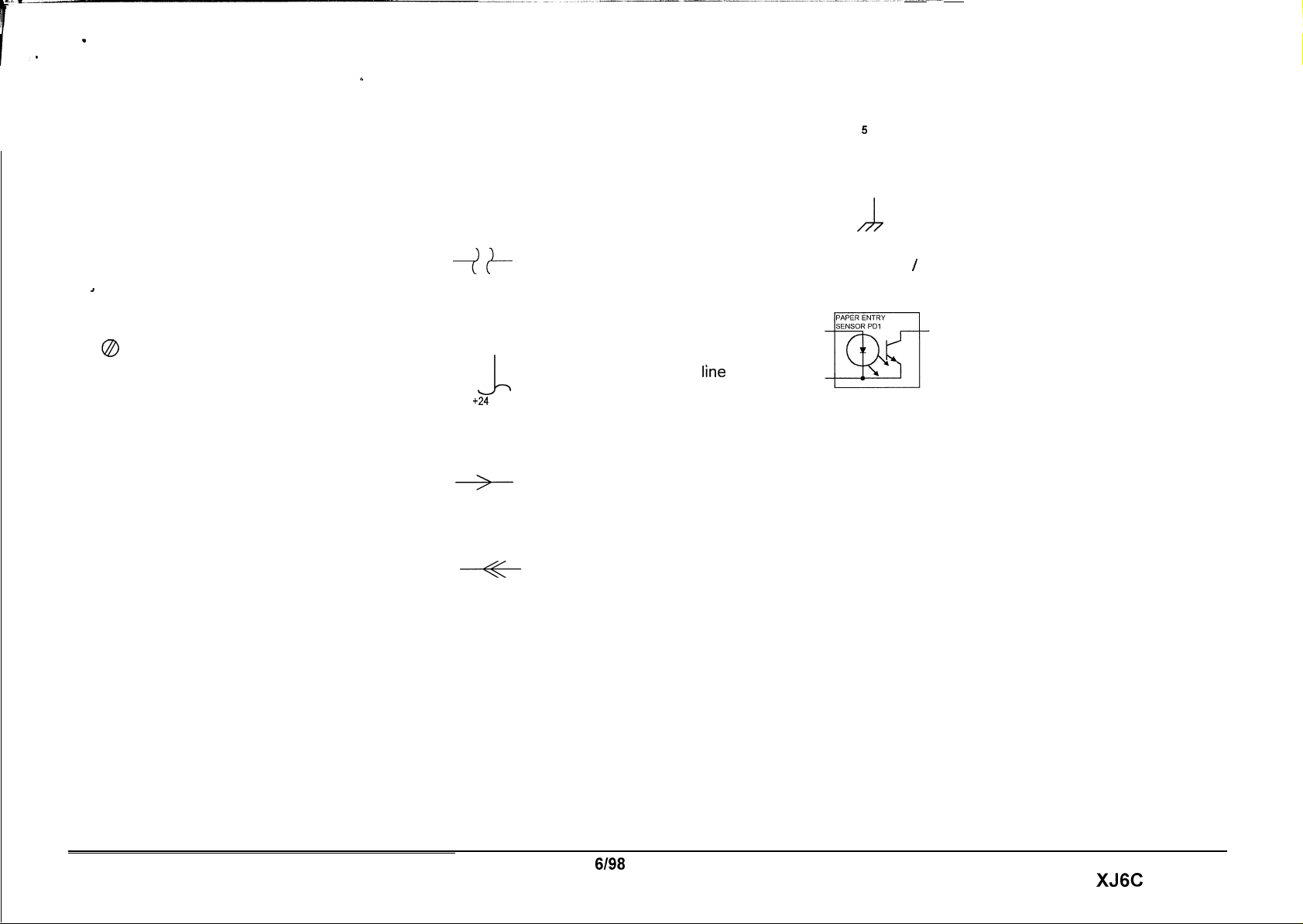
REFERENCE SYMBOLOGY
b
SPECIAL SYMBOLS
Flag
Notes, adjustments, and parts lists support the
checklists and the RAP information. The symbols symbols are included in order to aid in
that refer to this supportive data are shown below.
Note
This symbol is used to refer to notes
1
0
Adiustments
Parts List
PL 10.6
PL 10.6
found on the same page.
ADJ 4.1 This symbol refers to an
adjustment procedure located in
Section 4 of this Service Manual. The
number adjacent to the symbol
indicates the number that is assigned
to that adjustment.
Refers to the parts list located in
Section 5 of this Service Manual. The
number after the PL designation
indicates the number that is assigned
to that part.
Descriptions
troubleshooting when using the RAP S.
Interrupt Horizontal Signal
7+
Standby Power Input
+24
VDC
Left to Right Flow
Feedback
of all commonly used graphic
This indicates the continuation of a
signal line which is interrupted in a
horizontal direction.
This indicates the continuation of a
stand by
interrupted in the vertical direction.
This indicates the direction of signal
flow.
This indicates a feedback signal.
power ’lrne
which
5
D
Ground
h
LED / Phototransistor Sensor
is
This is used to identify an area of a
Circuit Diagram that you should
check.
This indicates a machine ground.
This type of sensor is used in the
paper path. It uses reflected light
to switch the sensor off and on.
Introduction
6198
vi
XJ6C
Page 7
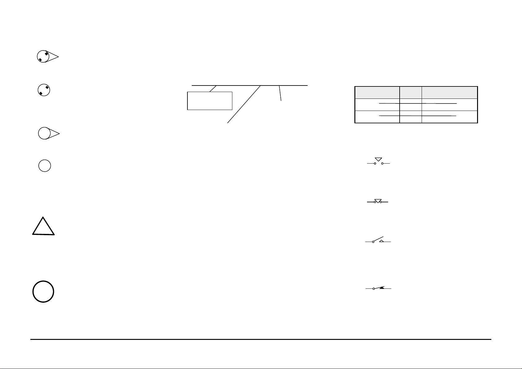
Without Tag Change
!
8
888
SIGNAL NOMENCLATURE
DC VOLTAGE LEVELS
This symbol indicates that the area
the triangle points to has not been
modified by the tag number in the
circle.
This symbol indicates that the entire
page has not been modified by the
tag number in the circle.
With Tag Change
This symbol indicates that the area
the triangle points to has been
modified by the tag number in the
circle.
This symbol indicates that the entire
page has been modified by the tag
number in the circle.
A warning is used to alert the
personnel to an operating or
maintenance procedure, practice, or
!
condition that, if not strictly
observed, could result in injury or
loss of life.
WARNING
The signal is named to imply the condition of the
machine when the signal is available. For
example:
DOCUMENT JAM SENSED (L) + 12 VDC
Signal Name
Logic state when the signal is
available in its named state. In
this case, the signal is Lo when
a document jam is sensed.
Logic voltage when
the signal is Hi.
DC voltages should be measured between the
test point and machine GND, unless instructed
otherwise. The table below shows the values of
the voltages.
Nominal Voltage Logic
State
+5 VDC H
L
+42VDC H
L
Actual Voltage
Ranges
+4.8 to +5.2 VDC
0.0 to +1.0 VDC
+39.0 to +44.0 VDC
0.0 to +3.0 VDC
Switches and Relay Contacts
Safety interlock switch that is
open.
Safety interlock switch that is
closed.
Switch or relay contacts with
momentary contacts shown
normally open.
CAUTION
A caution is used to alert the personnel
to an operating or maintenance
procedure, practice, or condition that, if
not strictly observed, could result in
damage to, or destruction of,
equipment.
6/98
Switch or relay contacts with
momentary contacts shown
normally closed.
XJ6C vii/viii Blank Introduction
Page 8

Section Contents
Title Page
Introduction..............................................1-3
Subsystem Maintenance
Printer Maintenance ...............................1-3
Initial Actions/System Checks
Initial Actions/System Checks.................1-4
Status Code Entry Chart......................... 1-5
System Checkout/ Final Action
System Checkout/Final
Action RAP.............................................1-6
1. Service Call Procedures
6/98 Service Call Procedures
XJ6C 1-1 Section Contents
Page 9

Introduction
Use the Service Call Procedures as a
maintenance guide when performing any service
on the XJ6C Printer. The procedure has been
designed for use with the XJ6C Printer Service
Manual.
• Printer Maintenance - This section contains a
list of the printer subsystem components to be
cleaned and /or lubricated and the cleaning
and lubricating materials to be used, when
that subsystem is accessed during a repair.
• Initial Actions / System Checks - This diagram
identifies and classifies the printer problem
and refers you to the appropriate RAP in
order to repair the problem. When the
problem has been repaired, perform the
System Checkout / Final Action.
• System Checkout / Final Action - This
procedure should be completed at the end of
every service call to ensure that the printer is
operating properly
Service Call Procedures 6/98
Introduction 1-2 XJ6C
Page 10

Printer Maintenance
Introduction
When the printer is being serviced, the following
maintenance procedure should be performed.
Procedure
Clean the following parts every time the printer is
serviced:
Description Procedure
Cover Clean using a Lint
Free Tissue
35P2163
(USCO/ACO) or
600S4372 (RXL)
and water.
Paper Feed roller Clean using a Lint
Free Tissue
35P2163
(USCO/ACO) or
600S4372 (RXL)
and water.
Paper Feed Pinch
rollers and Paper
Feed Guide
Maintenance Station Clean using a Lint
Clean using a Lint
Free Tissue
35P2163
(USCO/ACO) or
600S4372 (RXL)
and water.
Free Tissue
35P2163
(USCO/ACO) or
600S4372 (RXL)
and water.
6/98 Service Call Procedures
XJ6C 1-3 Printer Maintenance
Page 11
Initial Actions
1. QUESTION THE OPERATOR.
2. VERIFY, CLASSIFY AND REPAIR THE PROBLEM.
STATUS INDICATOR
• ERROR LED ON
Go to Error LED On RAP
• LOW INK LED(s) ON
Go to Low Ink LEDs On RAP
• POWER LED BLINKING
Go to Power LED Blinking RAP
• NO LEDs ON
Go to the 1.1 Power On RAP
PRINT QUALITY
• IMAGE QUALITY PROBLEMS
Go to IQ 1 Image Defect Entry RAP
in Section 3
OTHER FAULTS
• DEAD MACHINE
Go to 1.1 Power On RAP
• SELECTION/INDICATION
PROBLEM
Go to 2.1 Selection/Indication RAP
• ALL OTHER PROBLEMS
Go to Section 2 contents
Service Call Procedures 6/98
Initial Actions / System Checks 1-4 XJ6C
Page 12

System Checkout / Final Action
Reset the Ink Level Sensing count to zero.
Perform the following:
• Install a slave Color Printhead with empty
ink cartridges.
• Run a Test Print.
• Remove the slave Printhead and install a
Color Printhead with full ink cartridges.
• Run a Test Print.
• The NVM counts are now set to zero.
Print a file.
Prints exit the printer.
Y N
Refer to Initial Action / System Checks to
begin your repair.
Evaluate the prints.
Image quality is acceptable.
Y N
Go to the image quality RAP identified by the
IQ 1 Image Defect Entry RAP (Section 3).
Print and check the “Printing Alignment Test
Pattern”. The alignment is good.
Y N
Go to ADJ 2.0 Printhead Alignment
Procedure.
Clean exterior of machine and provide a sample
of the Test Print.
6/98 Service Call Procedures
XJ6C 1-5 System Checkout / Final Action
Page 13

Section Contents
2. Repair Analysis Procedures (RAPs)
Title Page
Status Indicators RAPS
Error LED On RAP....................................... 2-2
Power LED Blinking RAP .............................2-2
Low Ink LED(s) On RAP ...............................2-3
Error LED Flashing RAP ............................... 2-5
Title Page
Other Faults
1.1 Power on RAP ........................................2-6
2.1 Selection/Indication RAP........................2-8
6.1 Carriage RAP........................................ 2-10
6.2 Encoder RAP........................................ 2-10
8.1 Paper Feed RAP...................................2-12
9.1 Blank Print RAP....................................2-14
6/98 Status Code Indicators
XJ6C 2-1 Section Contents
Page 14

Error LED On RAP
A B C D
Go to 8.1 Paper Feed RAP.
Power LED Blinking RAP
Initial Action:
Ensure a color print head is installed.
Remove the power cord from the printer for 10
seconds, then reinstall it.
Press the Power switch.
The Error LED is on steady.
Y N
The Error LED is flashing.
Y N
Press and hold the Resume/FF button for
2 seconds to print the demo print.
The Error LED is on steady.
Y N
The error LED is flashing.
Y N
Check the interface cable and
connectors for an open wire or
bad connection. If OK, replace
the Main PWB.
Go to Error LED Flashing RAP.
Remove the power cord from the printer
for 10 seconds, then reinstall it.
Press and hold the Power switch for about
2 seconds.
The carriage was noisy.
Y N
The print head stopped at each ink
cartridge during the power-on
cycle.
Y N
Go to 6.2 Encoder RAP.
A B C D
Go to 6.1 Carriage RAP.
Go to Error LED Flashing RAP.
One or more low ink LED(s) are blinking.
Y N
Go to 6.1 Carriage RAP.
Go to Low Ink LED(s) On RAP.
Remove the power cord from the printer for 10
seconds, then reinstall it.
The Power LED blinks.
Y N
Printer is OK.
Go to 2.1 Selection/Indication RAP.
Status Code Indicators 6/98
Error Lamp On RAP / Power LED Blinking RAP 2-2 XJ6C
Page 15
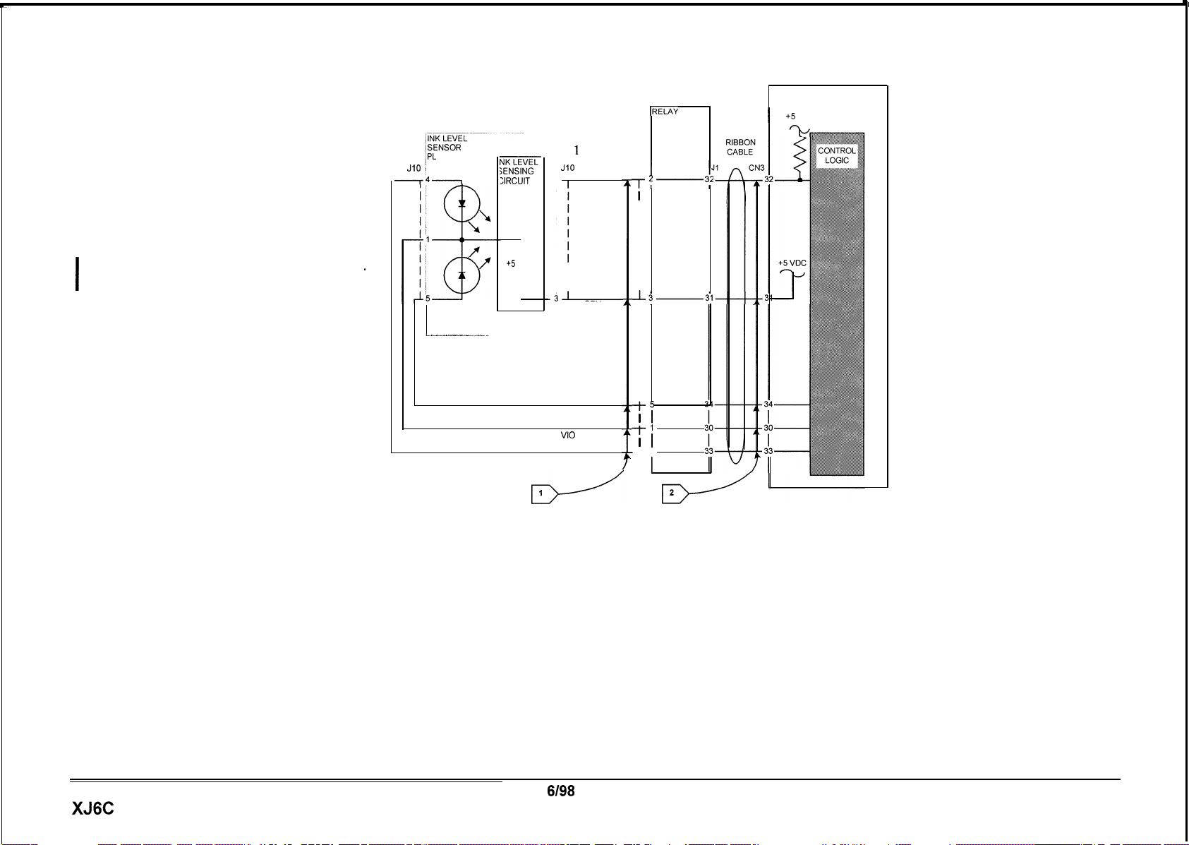
Low Ink LED(s) On RAP
Initial Action:
Ensure all the ink cartridges are full and
properly seated.
Go to Flags 1 and 2. Check the wires
connections for an open circuit. The wires
good.
Y N
Repair the wires or connections if poss
If the problem still exists replace
I
I Printer.
Replace the Ink Level Sensor (PL 2.1). If the
problem still exists replace the Printer.
and
are
i
ble
the
MAIN PWB
IRELAY
PWB
PL 2.1
iSENSOR
/PL
2.1
JIO 1
-k------l
NK
SENSING
ZIRCUIT
GND
T
+5
.
VDC
T
0
Pulsed signal
Low Ink sensed
(2.5 to 4 VDC).
&
Notes ,
-2
_j-
0
JlO
1
GRY
I
GRY
VI0
GRY
1
Low Ink
Sensed
GRY
P/J2
I
T2-
I
I
I
I
I
I
I
I
-L
I
I
I
I
I
I
I
I
t-5
1
I
-l-j
I
I
-4
I I
I
3;
PL 1.1
I
+5
VDC
XJ6C
6198
2-3
Status Code Indicators
Low Ink LED(s) On RAP
Page 16

PAGE INTENTIONALLY BLANK
Status Code Indicators 6/98
2-4 XJ6C
Page 17
h
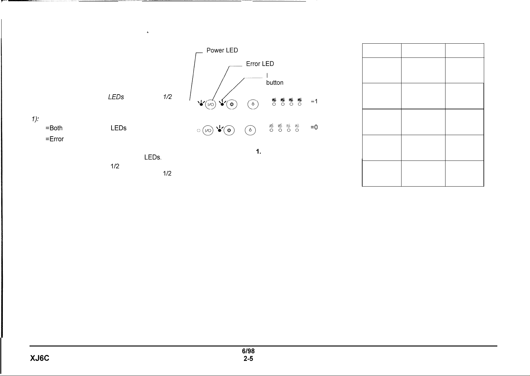
Error LED Flashing RAP
Note: This procedure will work only when the
Error LED is flashing.
Note: In the following procedure, the Error LED
and Power LED will be used to display an 8 bit
binary error code. The
second intervals.
at a time.
s
,
V
1
The LED code is as follows (See Figure
=Both
Error and Power
The code will be displayed 4 bits
0 =Error LED only is lit
1. Press and release the Resume/FF button,
while observing the Error and Power
2. 4 bits will be flashed in
followed by a pause, then 4 more bits in
second intervals. After the cycle, the Error
LED will continue to flash.
3.
Determine the code and go to the Error Code
Chart (Table 1) for the corrective action.
4.
Repeat step 1 as many times as necessary to
determine the code.
LEDs
will flash in
LEDs
lit
LEDs.
l/2
second intervals
l/2
l/2
Resume/FF
Figure I. LED Code
Error Error
Code
1000 1000
1000 1100
1100 1000
Description
ROM error
RAM error
EPROM
error
1110 1000 CPU error
1100 1111
Carriage
home Carriage
position error RAP
Table 1. Error Code Chart
Corrective
Action
Replace
the
main
PWB
Replace
the
main
PWB
Replace
main
the
PWB
Replace
the
main
PWB
Go to 6.1
XJ6C
6198
2-5
Status Code Indicators
Error LED Flashing RAP
Page 18
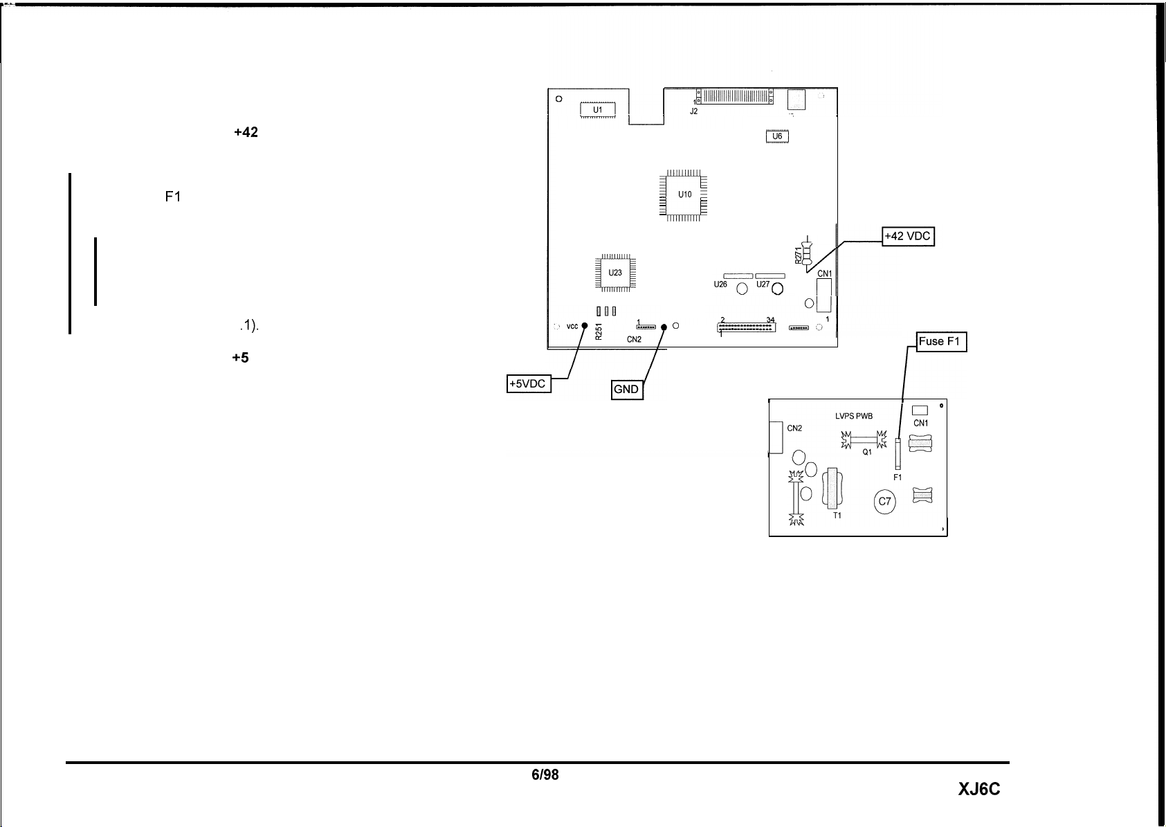
1.1 Power on RAP
Refer to Figure 1. There is
the Main PWB.
Y N
Disconnect the power cord.
Check fuse Fl on the LVPS.
Fl is blown.
Y N
Go to Flag 1 (Figure 2) and check the wires
for an open circuit. If good, replace the
LVPS. If problem still exists, replace the
Main PWB.
+42
VDC measured on
U23
xl!
-
-
-
-
-
UIO
L
-
-
-
-
- -
-
-
I2
I
MAIN PWB
J3
U6
;=
2
ti
CNI
r-l
Replace the LVPS (PL 1
Refer to Figure I. There is +5 VDC measured on
the Main PWB.
Y N
Go to Flag 2 and check for a short to ground. If
OK, replace the LVPS. If problem still exists,
replace Main PWB.
I
Replace the Main PWB before replacing the Control
Console PWB.
.I).
0
CN3
’
Figure 1. Voltage Measurements
33
CN4
I
0
Fuse
Fl
P
I
I
O
CNl
F?
,
Status Code Indicators
1.1 Power On RAP
6198
2-6
XJ6C
Page 19
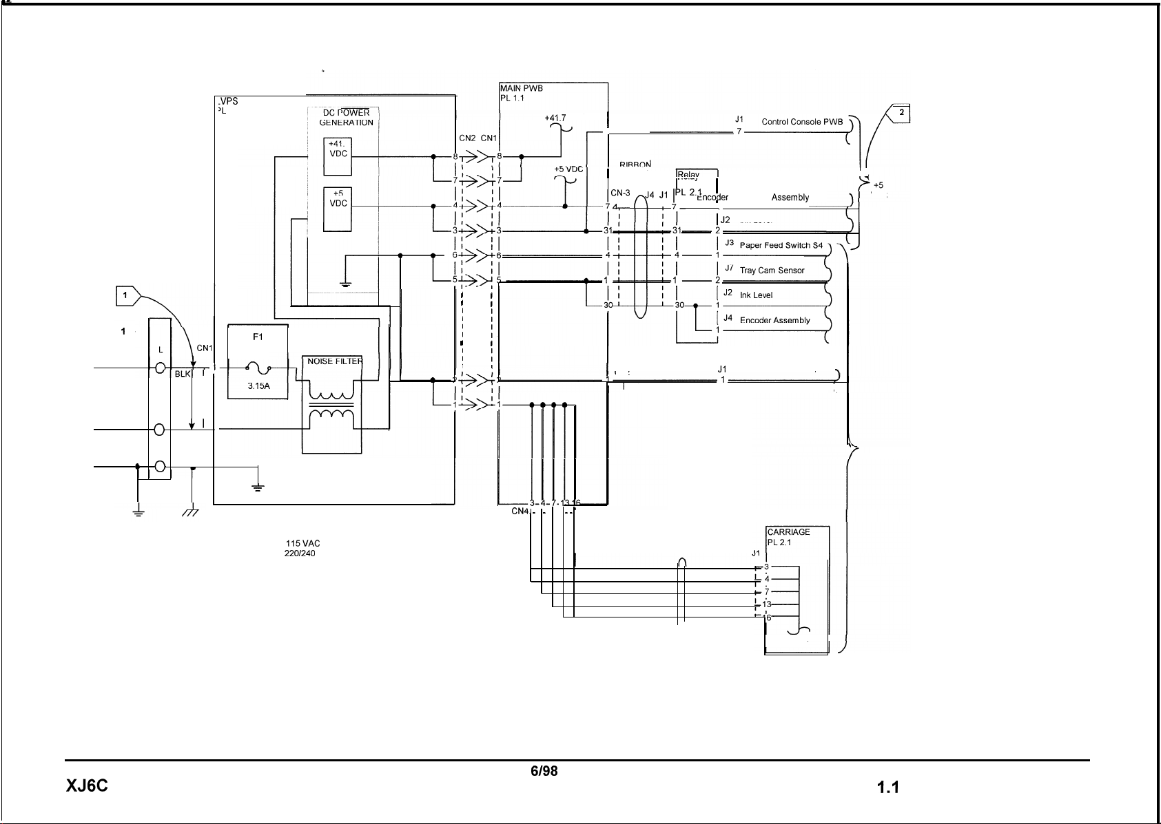
1
0
ACH
NEUTRAL
GROUND
_VPS
‘L
1.1
I
I
I
I
I
I
I
I
I
I
I
Fl
FUSE
1
I
WHT
VI
w
I
I
3
Notes ,
0
-
=
ACH =
115VAC
= 220/240 VAC (50HZ)
N
’
G
A
w
I
I
I
I
I
I
I
I
I
+41.7 VDC
CN4. _ . _ . . . _
I
CN2
7
GRY
RlRRnN
1
CABLE
,CN-3 n
/L
J4
I
CN2
RED
_
.
‘_‘--I
PWB
J1 ” 2’1
I
PRINTHEAD
RIBBON
CABLE
PL 2.1
Encoder
I
i J2
Ink Level
J1
Control Console PWB
Assembly
II
VDC
1
1
1
GND
XJ6C
Figure 2. Power distribution
6198
2-7
3
GND
Status Code Indicators
1.1 Power On RAP
Page 20

2.1 Selection / Indication RAP
Load paper.
Disconnect and then reconnect the power cord
while observing the LEDs.
All LEDs light momentarily when the power
cord is reconnected.
Y N
One or more LEDs light.
Y N
Go to 1.1 Power On RAP.
Go to Flag 1 and Flag 2 and check for an
open wire. If OK, replace the Control Console
PWB .
All LEDs go out in approximately 10 seconds.
Y N
If the Power LED remains on (flashing), go to
Flag 3 and check for an open wire. If OK,
replace the Control Console PWB.
Press and hold the Power button for
approximately 2 seconds to turn on the printer.
Press and hold the Resume/FF button for 2
seconds.
Paper feeds.
Y N
Go to Flag 5 and check for an open wire. If
good, go to 8.1 Paper Feed RAP.
A
Press the Cartridge Change button.
The carriage moves to the center position.
Y N
Go to Flag 4 and check for an open wire. If
OK, replace the Control Console PWB.
For printer set up problems when printing from a
DOS application, consult GP 2 Printing with DOS
Procedure in Section 6.
A
Status Code Indicators 6/98
2.1 Selection / Indication RAP 2-8 XJ6C
Page 21
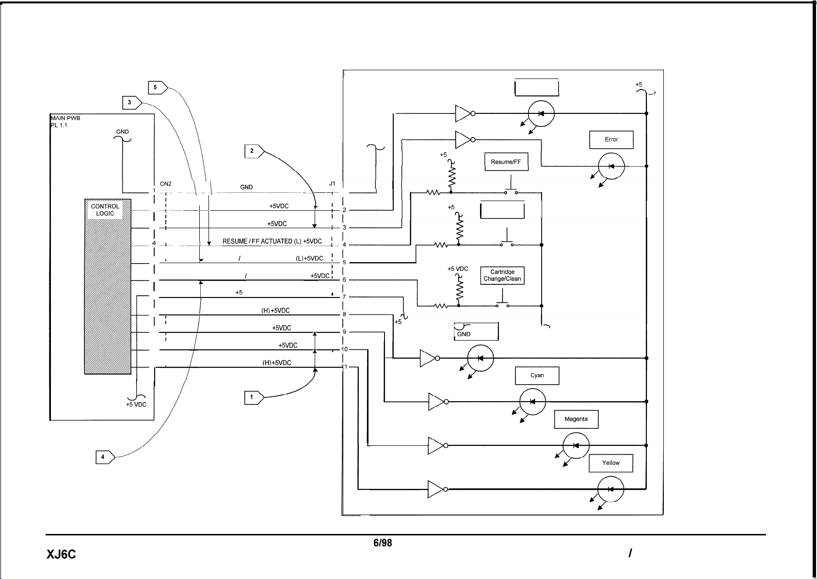
CONTROL CONSOLE PWB
I;
I
PL 1.1
GND
+5
Power On
I
+5
VDC
?J
I
VDC
_~ A_ _ 1.
i
I
2
-_I- _ _~_ ____ ______.
I
I
I
3
I
I
I
I
I
4
--I---
_
__~-.__!L_
I
I
I
I
5
I
I
I
CARTRIDGE CHANGE / CLEAN ACTUATED (L)
I
6
I
I
I
I
I
I
I
I
8
I
I
I
9
I
I
I
10
I
I GRY
I
I
11
__.__-GND-__.-._ __
PWR ON LED (H)
w
POWER / RESET ACTUATED
BLACK INK LED
I
CYAN INK LED (H) +5VDC
I
MAGENTA INK LED (H)
YELLOW INK LED (HI +5VDC
RED
+SVDC
GRY
ERROR LED (H)
RESUME ’ FF *CT”*TEDo+5VDC_:---.
+5
GRY
GRY
GRY
GRN
VDC
GRY
GRY
GRY
GRN
+SVDC
(H) +SVDC
+SVDC
\ --
1
(L) +SVDC
+SVDC
T
A
AA
’
Jl
r-
1
-
i
I
;
I
I
I
I
I
I
+5 VDC
%
I
Power/Reset
I
I I
I
!
I
;
I
I
I
I
I
I
I
I
I
I
I
I
L
+5
rt
VDC
I
1
Black
&
I
1
XJ6C
6198
2-9
Status Code Indicators
2.1 Selection I Indication RAP
Page 22

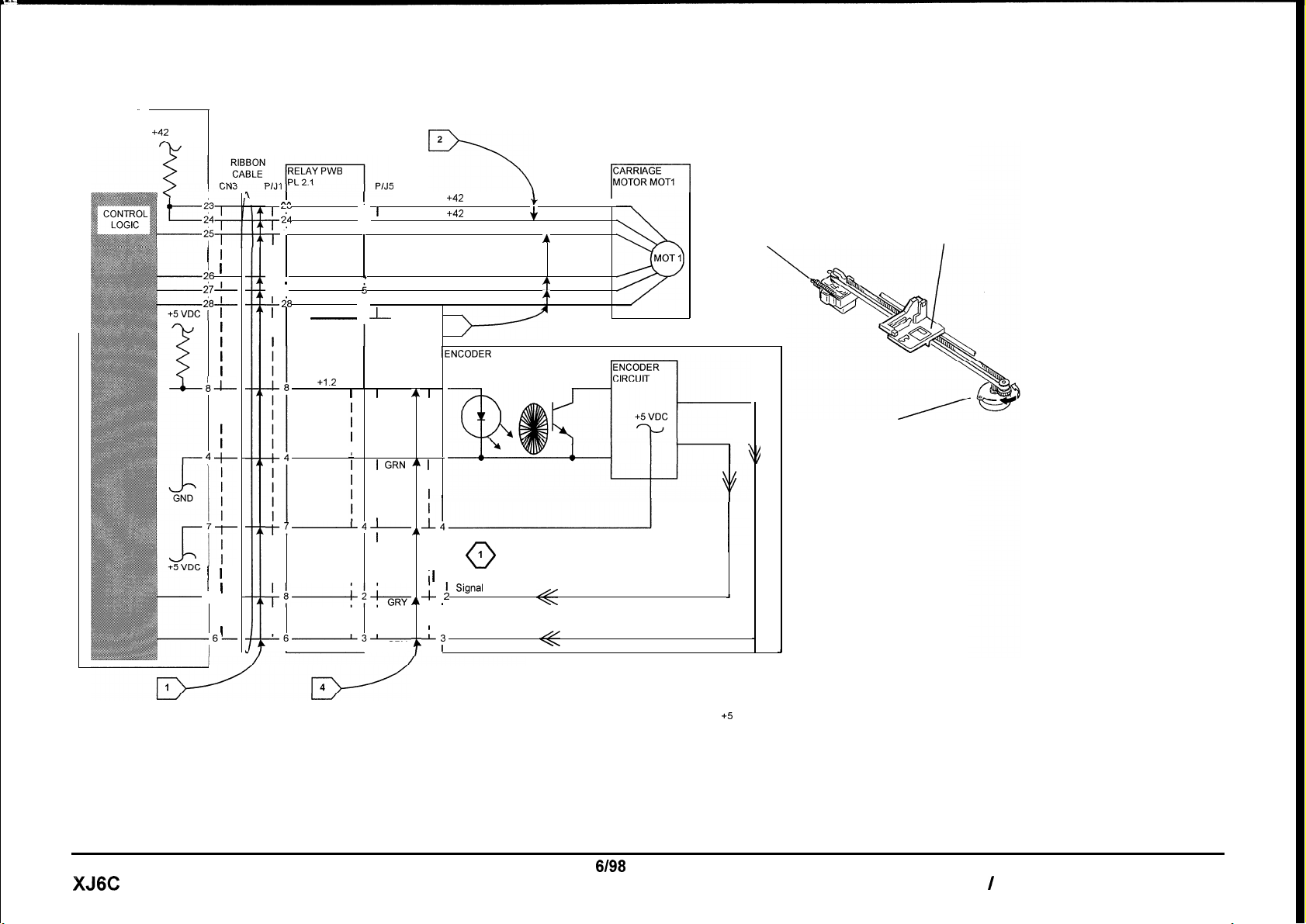
6.1 Carriage RAP
6.2 Encoder RAP
Disconnect and then reconnect the power cord.
Press and hold the Power switch.
The carriage moves.
Y N
• Go to Flag 1 and check the ribbon cable
for being open or damaged.
• Go to Flag 2 and check for an open
circuit. If the wire is good, replace the
Main PWB.
• If problem still exists, replace the printer.
Perform the following:
• Check that the Printhead ribbon cable going
to CN4 on the Main PWB is connected
properly.
• Go to Flag 2 and Flag 3 and check for an
open circuit.
• If the wires are good, replace the Printhead
Ribbon Cable (PL 2.1).
• If the problem continues, replace the Main
PWB (PL 1.1).
• If the problem still exists replace the printer.
• Go to Flag 4 and check for an open circuit.
• Replace the Encoder.
• Go to 6.1 Carriage RAP.
Status Code Indicators 6/98
6.1 Carriage RAP / 6.2 Encoder RAP 2-10 XJ6C
Page 23
MAIN PWB
PL 1.1
+42 VDC
2
I
i6
i7-
i8-
I 1
a--
p-t
I
1
-8
-66
I
_A
I
ill
l-m
25
T
’
’
I
I
I I
I I
-26
I
’
-27
I
-i8
I
I
N/C
-
I
Led On
(H)) +I .2 VDC
l
I
‘4’
t7
I
I
’
I
r
I
I
I
++2%ir
I
I
-6-3’
I
:1
!
2
3
4
6
7
I
I
I
I I
I I
I I
I I
I I
, GRY
I
I
I
I
I
J-
P/J4
I
GRY AI
I I
I I
I I
I I
i GRN ” t
I I
I I
I
I
1
GRY
Y
+42 VDC
+42 VDC
Carriage Step 0 Signal
Carriage Step 1
Carriage Step 2 Signal
Carriage Step 3 Signal
3
IENCODER
PL2.1
P/J9
5
1
1i
I
I
I
; 1
-;_
AL
I
I I
’
I Signal
--L3
1
I
0
Carriage Position
1
Signa’
.
Carriage Position
I
J+
RED
A
BRN
q
YEL
4
RED
BLK
ORN
I
1
J
Encoder
Carriage
Carriage Motor
MOT1
XJ6C
NOTES: ,
0
WHEN THE CARRIAGE IS NOT MOVING,
THE VOLTAGE IS EITHER +5 VDC OR 0
VDC.
WHEN THE CARRIAGE IS MOVING, THE
VOLTAGE IS APPROXIMATELY 2.6 VDC.
6198
2-l 1
Status Code Indicators
6.1 Carriage RAP / 6.2 Encoder RAP
Page 24

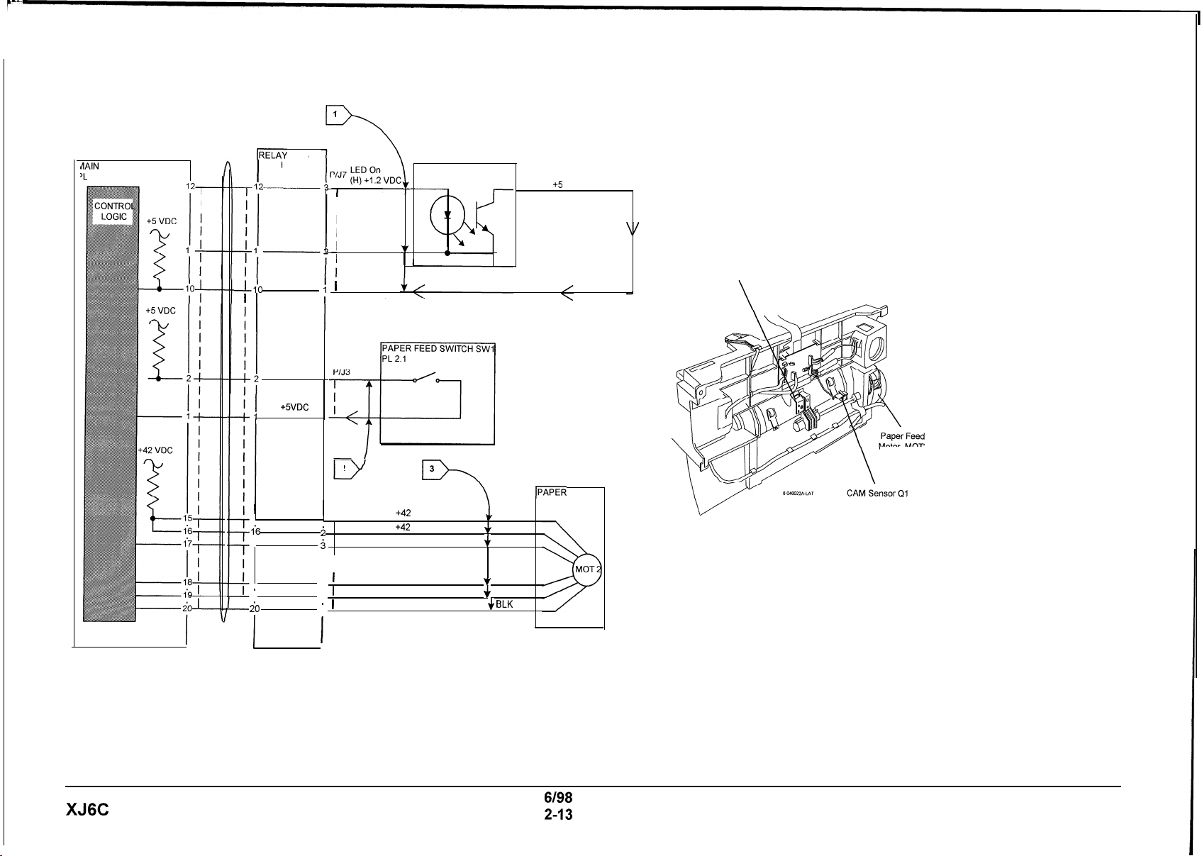
8.1 Paper Feed RAP
Clear any paper in the printer.
Disconnect and then reconnect the power cord.
Press and hold the Power switch for about 2
seconds.
Press and hold the Resume/FF button for 2
seconds to print the demo print.
The paper feeds or partially feeds.
Y N
• Check that the Paper Tray is installed
correctly (REP 1.1)
• Go to Flag 1 and check the cam sensor
circuit for an open.
• If OK, go to Flag 3 and check for an open
circuit. If paper feed motor circuit is
defective, replace the printer.
• If the wires are good, replace the Main
PWB.
• Go to Flag 2 and check the paper feed switch
circuit for an open.
• If OK, go to Flag 3 and check for an open
circuit. If paper feed motor is defective,
replace the printer.
• Replace the Retard Pad.
• If the problem still exists, replace the Main
PWB before replacing the printer.
Status Code Indicators 6/98
8.1 Paper Feed RAP 2-12 XJ6C
Page 25
dAIN PWB
‘L
1.1
RIBBON
CABLE IRELAY PWB
CN3
P/J 1
-Go
1
I
I
I
I
15
l-6
1’7
I
I
18
I
’
I
19
I
i0
l-
I
I
PL 2.1
I
WHT
Paper Sensed
(H) +SVDC
BLK
1
I
2
1
P/J6
I
1
i
i
I
I
4
I
.
5
’
.
6
’
I
J
CAM SENSOR Ql
1
WHT
I
I
I
I
I
I
2
v
BLK
1
RED
+42 VDC
+42 VDC
Paper Feed Step 0 Signal
Paper Feed Step 1
Paper Feed Step 2 Signal
Paper Feed Step 3 Signal + BLK
Cam
(L) +5 VDC
a
w
3
IPAPER FEED
7
+
RED
+
RED
v
$
YEL
MOTOR MOT2
BRN
ORN
Paper Feed
Switch
Motor MOT2
XJ6C
6/98
2-13
Status Code Indicators
8.1 Paper Feed RAP
Page 26

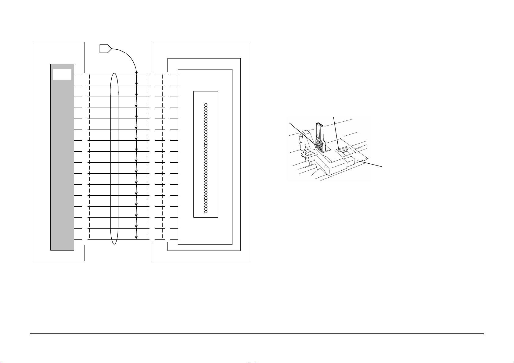
9.1 Blank Print RAP
Initial Action:
Ensure that the Printhead latch is positioned
towards the rear.
Unlatch the Printhead, reset the Printhead and
latch it back into position. If problem still exists:
• Replace the Printhead.
• Go to Flag 1 and check the ribbon cable for
being damaged.
• Check the terminals of J11 on the Carriage
Assembly and J12 on the Ink Cartridge for
being contaminated or damaged. Clean or
repair as necessary.
• If the problem still exists, replace the
Printhead Ribbon Cable (PL 2.1).
Status Code Indicators 6/98
9.1 Blank Print RAP 2-14 XJ6C
Page 27
MAIN PWB
RIBBON
PL 2.1
PL 1.1
I
CONTROL
LOGIC
J11
10
1
12
13
14
CARRIAGE
PL 2.1
IPRINTHEAD CARTRIDGE
PL 2.2
J12
1
1
2
2
3
3
4
4
5
5
6
6
7
7
8
8
9
9
10
1
12
13
14
PRINTHEAD CONTROL
LOGIC
IPRINTHEAD
NOZZLES
J12
J11 (under carriage)
Carriage
1
PRINTHEAD
CABLE
CN4
1
2
3
4
5
6
7
8
9
10
1
12
13
14
15
15
16
15
16
16
6/98 Status Code Indicators
XJ6C 2-15 9.1 Blank Print RAP
Page 28

Section Contents
Title Page
Image Quality Analysis RAPs
IQ 1 Image Defect Entry RAP....................3-2
3. Image Quality
6/98 Image Quality RAPs
XJ6C 3-1 Section Contents
Page 29
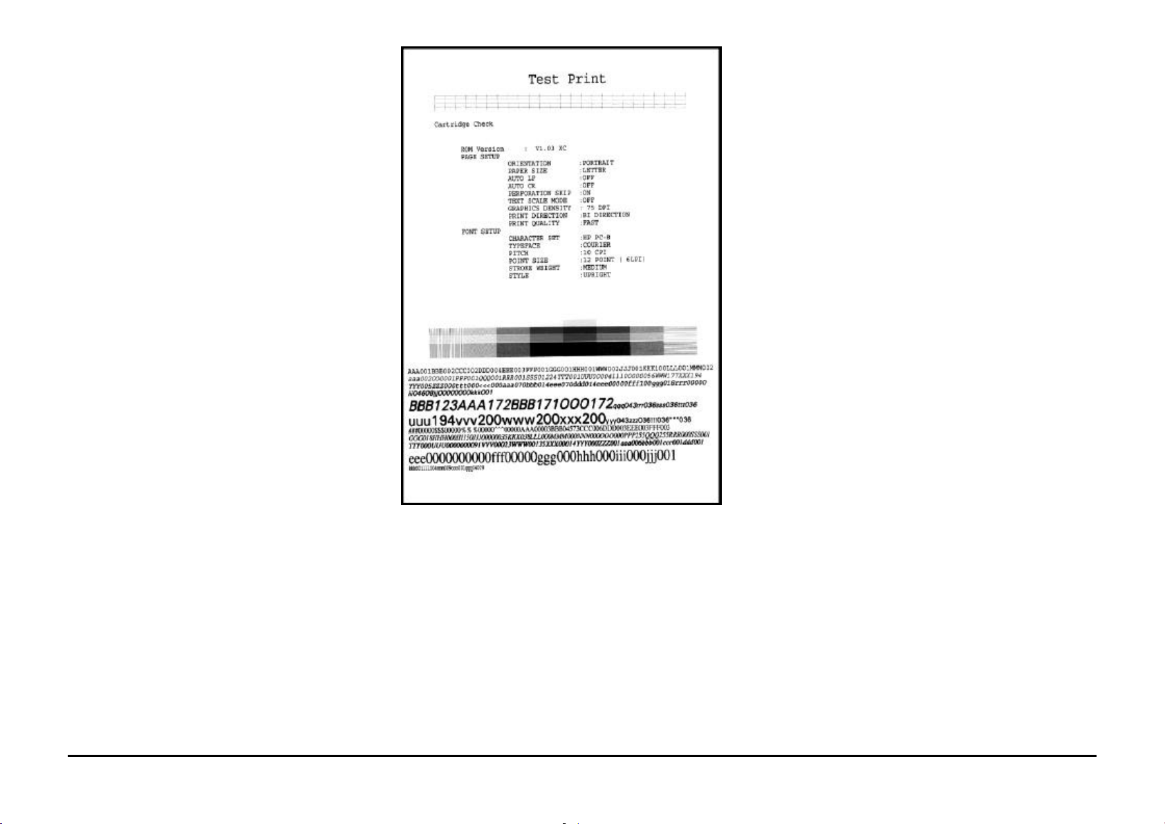
IQ 1 Image Defect Entry RAP
1. Print the Test Print:
a. Load paper into the Paper Tray.
b. Press and hold the Power on / Reset
button for approximately 2 seconds and
then release, to switch the Printer power
off.
c. While pressing and holding the
Resume/FF button press and release the
Power on / Reset button. The printer
prints the test print shown in Figure 1.
When the test print is complete, the printer
initializes and returns to the Ready status.
d. If the test print fails to print, repeat steps a
through c.
2. Refer to the DEFECT Column in Table 1 that
best describes the image quality problem.
3. If the problem is with external input only,
replace the Main PWB.
Figure 1. Test Print
Image Quality RAPs 6/98
IQ1 Image Defect Entry RAP 3-2 XJ6C
Page 30

DEFECT CAUSE SOLUTION
3. Image Quality
Blank print
White horizontal lines
and Streaks
Print is faint or missing
Blurry or Jagged vertical
lines
• Printhead
• The Printhead nozzles may be
blocked.
• A non recommended paper is
being used or the paper is
damp.
• Defective Cartridge
• The ink supply may be nearly
empty.
• The Print Head nozzles may be
blocked.
• Print Head alignment
• Paper
1. Remove and reinstall the Print Head.
2. Press the Cartridge Change / Clean button for 2 seconds to clean and
restore the Print Head. Repeat if necessary.
If the problem still exists go to the 9.1 Blank Print RAP.
Perform the following:
1. Press the Cartridge Change / Clean button for 2 seconds to clean and
restore the Print Head.
2. Make another Test Print. If the print still has lines and streaks repeat the
above process up to 5 times.
3. If the problem still exists, replace the Print Head.
Replace the paper.
Perform the following:
1. Press and hold the Cartridge Change / Clean button for 2 seconds to
clean and restore the Print Head..
2. Run a Test Print. If the print is still faint, Repeat the process 2 more
times.
3. If the problem is still not corrected replace the Print Head.
Perform ADJ 2.0 Printhead Alignment Procedure
If the problem still exists switch the printer to the High Quality print mode.
Turn the paper over to print on the opposite side.
Print image is clipped or
off edge of media
• Print off edge of media
• Document margins may exceed
printer margins.
Ensure that the Print Driver setup has the correct selection of media size and
type.
Adjust margins in the application as necessary.
Table 1. Image Defect Table
6/98 Image Quality RAPs
XJ6C 3-3 Section Contents
Page 31

Section Contents
Title Page
Repairs
REP 1.0 Printhead.................................4-2
REP 1.1 Paper Tray..............................4-3
REP 1.2 Top Cover............................... 4-4
REP 1.3 Main Cover..............................4-5
REP 1.4 Exit Guide...............................4-7
REP 1.5 Paper Feed / Carriage Assy.....4-8
REP 1.6 LVPS Assembly.....................4-11
REP 1.7 Main PWB.............................4-12
REP 1.8 Waste Ink Pad.......................4-14
REP 1.9 Pump ....................................4-15
REP 1.10 Maintenance Station..............4-16
REP 1.11 Encoder.................................4-18
4. Repairs / Adjustments
REP 1.12 Control Console PWB ...........4-20
REP 1.13 Paper Tray Switch (SW 1).....4-21
REP 1.14 Retard Pad............................4-22
REP 1.15 Printhead Ribbon Cable.........4-24
REP 1.16 Ink Level Sensor ...................4-27
REP 1.17 Carriage Latch Lever.............4-28
Adjustments
ADJ 2.0 Printhead Alignment.............. 4-29
6/98 Repairs / Adjustments
XJ6C 4-1 Section Contents
Page 32

REP 1.0 Printhead
lock lever
Parts List on PL 2.2
Removal
1. Open the Top Cover (PL 1.1).
2. Center the carriage using either of the following
procedures:
• Press the Cartridge Change / Clean
button.
WARNING
Switch off the power. Disconnect the power
cord from the wall outlet.
• Grasp and manually move the belt
(PL 2.1) in order to center the Printhead
(Figure 1).
Printhead
CAUTION
Store the Printhead in the Storage Box. Leaving
the Printhead removed for long periods of time will
cause the ink nozzles to dry out. Image quality
defects or a blank page could result. If necessary,
prime the Printhead after reinstallation .
3. Move the Printhead lock lever toward the front
of the printer.
4. Lift and remove the Printhead. Store it in the
Storage Box.
Replacement
1. Install the Printhead onto the Printhead vertical
guide.
2. Move the Printhead lock lever toward the rear
of the printer.
3. Close the Top Cover.
4. Press the Resume / FF button to prime the
Printhead.
belt
belt
Printhead
0400101A-LAT
Figure 1.
Repairs 6/98
Cartridge
Change / Clean
Resume / FF
REP 1.0 4-2 XJ6C
Page 33

REP 1.1 Paper Tray
0400112A-LAT
Parts List on PL 1.1
Removal
1. Remove the Paper Output Shelf (PL 1.1).
2. Press the two handles toward the rear of the
printer to release the latches (Figure 1).
3. Pivot the Paper Tray toward the back of the
printer to disengage the three tabs at the bottom
of the Paper Tray from the tabs on the Paper
Feed / Carriage Assembly.
4. Lift the Paper Tray from the printer.
Paper
Tray
Handles
Replacement
1. Retract the moveable face of the Paper Tray by
pressing it toward the back of the Paper Tray.
2. Insert the Paper Tray into the printer ensuring
the moveable face is behind the cam (Figure 2).
3. Engage the three tabs at the bottom of the
Paper Tray with the tabs on the Paper Feed /
Carriage Assembly.
4. Rotate the Paper Tray toward the front of the
printer.
5. Engage the two latches by gently pulling the
handles downward and toward the front of the
printer until the latches snap into position.
6. Reinstall the Paper Output Shelf.
Cam must be
positioned here
0400111A-LAT
Figure 1.
Figure 2.
6/98 Repairs
XJ6C 4-3 REP 1.1
Page 34

REP 1.2 Top Cover
Parts List on PL 1.1
Removal
1. Open the Top Cover (PL 1.1).
2. Utilizing a screwdriver or similar tool, slightly
separate the Top Cover and Main Cover at
either pivot to release the Top Cover pivot from
the Main Cover (Figure 1).
3. Lift the Top Cover from the printer.
Top
Cover
Replacement
1. Insert either Top Cover pivot into the
corresponding Main Cover pivot hole.
2. Utilizing a screwdriver or similar tool, slightly
separate the Top Cover and Main Cover at the
opposite pivot.
3. Position the Top Cover pivot to engage with the
pivot hole of the Main Cover.
4. Close the Top Cover.
Main
Cover
0400121A-LAT
Figure 1.
Repairs 6/98
REP 1.2 4-4 XJ6C
Page 35

REP 1.3 Main Cover
Parts List on PL 1.1
Removal
CAUTION
Store the Printhead in the Storage Box. Leaving
the cartridge removed for long periods of time will
cause the ink nozzles to dry out. Image quality
defects or a blank page could result. If necessary,
prime the Printhead after reinstallation .
1. Remove the Printhead (REP 1.0). Store the
Printhead in the Storage Box.
WARNING
Switch off the power. Disconnect the power
cord from the wall outlet.
2. Remove the Paper Output Shelf (PL 1.1).
3. Remove the Paper Tray (REP 1.1).
4. Remove the Top Cover (REP 1.2).
5. Lay the printer on it’s back; release the three
front latch tabs (Figure 1).
CAUTION
While removing the Main Cover from the printer,
take care not to damage the ribbon cable that is
connected to the Control Console PWB, which is
located inside the Main Cover.
NOTE: The rear of the Main Cover has three
locator tabs and two latch tabs.
6. Return the printer to its normal operating
position. Lift and hold the front of the cover
slightly while releasing the two rear latch tabs.
Then lift the rear of the cover and pivot towards
the FRONT of the printer to remove.
Replacement
1. Ensure the ribbon cable is properly routed and
not twisted during Main Cover installation.
2. If previously disconnected, reconnect ribbon
cable to the Control Console PWB.
3. Position the Main Cover on the printer. Align
and latch the rear latches; then the front
latches.
4. Reinstall the following:
a. Top Cover (REP 1.2)
b. Paper Tray (REP 1.1)
c. Paper Output Shelf (PL 1.1)
d. Printhead (REP 1.0)
latch tabs
Figure 1.
6/98 Repairs
0400131A-LAT
XJ6C 4-5 REP 1.3
Page 36

PAGE INTENTIONALLY BLANK
Repairs 6/98
4-6 XJ6C
Page 37

REP 1.4 Exit Guide
apply
Parts List on PL 2.2
Removal
CAUTION
Store the Printhead in the Storage Box. Leaving
the Printhead removed for long periods of time will
cause the ink nozzles to dry out. Image quality
defects or a blank page could result. If necessary,
prime the Printhead after reinstallation .
1. Remove the Printhead (REP 1.0). Store the
Printhead in the Storage Box.
WARNING
Switch off the power. Disconnect the power
cord from the wall outlet.
2. Remove the Paper Output Shelf (PL 1.1).
3. Remove the Top Cover (REP 1.2).
4. Position both thumbs at the lower, front corners
of the Exit Guide (Figure 1). Apply modest
pressure simultaneously toward the rear and up
to unlatch the Exit Guide.
5. Rotate the guide approximately 90° up and
toward the rear of the printer.
6. Lift the Exit Guide from the printer.
Replacement
1. Hold the Exit Guide so the star wheels (10) are
facing the front of the printer.
2. Lower the Exit Guide into the printer to engage
the pivots with the slots in the Paper Feed /
Carriage Assembly.
3. Rotate the Exit Guide completely toward the
front of the printer.
4. Position both thumbs at the lower, front corners
of the Exit Guide (Figure 1). Apply moderate
pressure simultaneously toward the rear and
down to latch the Exit Guide.
5. Reinstall the Top Cover (REP 1.2).
6. Reinstall the Paper Output Shelf (PL 1.1).
7. Reinstall the Printhead (REP 1.0).
Exit Guide
pressure
here
Figure 1.
0400141A-LAT
6/98 Repairs
XJ6C 4-7 REP 1.4
Page 38

REP 1.5 Paper Feed / Carriage
Assembly
Parts List on PL 2.1
Removal
CAUTION
Store the Printhead in the Storage Box. Leaving
the Printhead removed for long periods of time will
cause the ink nozzles to dry out. Image quality
defects or a blank page could result. If necessary,
prime the Printhead after reinstallation .
1. Remove the Printhead (REP 1.0). Store the
Printhead in the Storage Box.
WARNING
Switch off the power. Disconnect the power
cord at the wall outlet.
2. Remove the Paper Output Shelf (PL 1.1).
3. Remove the Paper Tray (REP 1.1).
4. Remove the Top Cover (REP 1.2).
5. Remove the Main Cover (REP 1.3).
6. Loosen screw; disconnect ground wire from
ground plate near front, left corner of Paper
Feed / Carriage Assembly (Figure 1).
7. Disconnect ground wire from grounding plate at
right side of printer (Figure 2).
ground wire
Figure 1. Left side
ground wire
0400151A-LAT
Figure 2. Right side
0400152A-LAT
Repairs 6/98
REP 1.5 4-8 XJ6C
Page 39

REP 1.5 Paper Feed / Carriage
remove
remove
disconnect
Assembly con’t.
Replacement
8. Remove the screws (2) from the two front
corners of the Paper Feed / Carriage Assembly
(Figure 3).
9. Lift the front of the assembly slightly, then slide
the assembly toward the front of the printer until
it contacts the front wall of the base.
10. Lift the front of the assembly to access the Main
PWB ribbon cable connectors, CN3 & CN4;
disconnect from the Main PWB (Figure 4).
11. Remove the assembly from the base.
1. Lift the front of the assembly to access the Main
PWB ribbon cable connectors, CN3 & CN4;
reconnect to the Main PWB
(Figure 4).
2. Allow the Paper Feed / Carriage Assembly to
rest on the printer base. Slide the assembly
rearward to engage the rear mounts.
3. Reinstall the two front screws
4. Reconnect the ground wire to the ground plate
on the right side of the printer.
5. Reconnect the ground wire to the ground plate
on the left, front corner of the printer; tighten
screw.
6. Reinstall the following:
a. Main Cover (REP 1.3)
b. Top Cover (REP 1.2)
c. Paper Tray (REP 1.1)
d. Paper Output Shelf (PL 1.1)
e. Printhead (REP 1.0)
Main
PWB
screw
screw
Figure 3.
6/98 Repairs
connectors
CN3 & CN4
0400154A-LAT
Figure 4.
XJ6C 4-9 REP 1.5
Page 40

PAGE INTENTIONALLY BLANK
Repairs 6/98
4-10 XJ6C
Page 41

REP 1.6 LVPS Assembly
0400161A-LAT
1. disconnect
3. disengage
Parts List on PL 1.1
Removal
CAUTION
Store the Printhead in the Storage Box. Leaving
the Printhead removed for long periods of time will
cause the ink nozzles to dry out. Image quality
defects or a blank page could result. If necessary,
prime the Printhead after reinstallation .
1. Remove the Printhead (REP 1.0). Store the
Printhead in the Storage Box.
WARNING
Switch off the Power. Disconnect the power
cord at the wall outlet.
2. Remove the Paper Output Shelf (PL 1.1).
3. Remove the Paper Tray (REP 1.1).
4. Remove the Top Cover (REP 1.2).
5. Remove the Main Cover (REP 1.3).
6. Remove the Paper Feed / Carriage Assembly
(REP 1.5).
7. Disconnect LVPS power cord connector CN1
from the LVPS (Figure 1).
8. Remove the four mounting screws.
9. Slide the LVPS toward the right side of the
printer to disengage LVPS connector CN2 from
the Main PWB connector CN1; lift the LVPS
from the printer.
Replacement
1. Position the LVPS into the printer base.
2. Slide the LVPS toward the left side of the
printer to engage LVPS connector CN2 with the
Main PWB (Figure 1).
3. Install the four mounting screws.
4. Reconnect the LVPS power cord connector
CN1.
LVPS
CN2
Main
PWB
5. Replace the following:
a. Paper Feed / Carriage Assembly
(REP 1.5)
b. Main Cover (REP 1.3)
c. Top Cover (REP 1.2)
d. Paper Tray (REP 1.1)
e. Paper Output Shelf (PL 1.1)
f. Printhead (REP 1.0)
CN1
XJ6C 4-11 REP 1.6
2. remove
screws (4)
6/98 Repairs
Figure 1.
Page 42

REP 1.7 Main PWB
Parts List on PL 1.1
Removal
CAUTION
Store the Printhead in the Storage Box. Leaving
the Printhead removed for long periods of time will
cause the ink nozzles to dry out. Image quality
defects or a blank page could result. If necessary,
prime the Printhead after reinstallation .
1. Remove the Printhead (REP 1.0). Store the
cartridge in the Storage Box.
WARNING
Switch off the power. Disconnect the power
cord at the wall outlet.
2. Remove the Paper Output Shelf (PL 1.1).
3. Remove the Paper Tray (REP 1.1).
4. Remove the Top Cover (REP 1.2).
5. Remove the Main Cover (REP 1.3).
6. Remove the Paper Feed / Carriage Assembly
(REP 1.5).
7. Remove the LVPS (REP 1.6).
8. Disconnect Main PWB connector CN2 from the
Main PWB (Figure 1).
NOTE: The two screws securing the PC interface
cable connector to the Main PWB are longer than
the others. Ensure to replace them in their correct
positions.
9. Remove the eight mounting screws and ground
wire (Figure 1).
ground
wire
NOTE: It may be necessary to unsecure the ribbon
cable and ferrite from the printer base before
removing the Main PWB.
NOTE: Exercise care not to deform the two PC
interface cable connector wire-form locks during
Main PWB removal.
10. Remove the Main PWB.
connector
CN2
mounting
screws (8)
Repairs 6/98
ferrite
0400171A-LAT
Figure 1. Main PWB
REP 1.7 4-12 XJ6C
Page 43

REP 1.7 Main PWB (con’t)
Parts List on PL 1.1
Replacement
NOTE: There are 2 different length screws
securing the Main PWB. Be sure to reinstall the two
longer screws through the PC interface cable
connector.
1. Position the Main PWB into the printer base.
2. Reinstall the ground wire as per Figure 1.
3. Reinstall mounting screws.
4. Reconnect connector CN2 to the Main PWB.
5. If previously unsecured, resecure ribbon cable
and ferrite to the printer base.
6. Replace the following:
a. LVPS (REP 1.6)
b. Paper Feed / Carriage Assembly
(REP 1.5)
c. Main Cover (REP 1.3)
d. Top Cover (REP 1.2)
e. Paper Tray (REP 1.1)
f. Paper Output Output Shelf (PL 1.1)
g. Printhead (REP 1.0)
6/98 Repairs
XJ6C 4-13 REP 1.7
Page 44

REP 1.8 Waste Ink Pad
Parts List on PL 1.1
Removal
CAUTION
Store the Printhead in the Storage Box. Leaving
the Printhead removed for long periods of time will
cause the ink nozzles to dry out. Image quality
defects or a blank page could result. If necessary,
prime the Printhead after reinstallation .
1. Remove the Printhead (REP 1.0). Store the
Printhead in the Storage Box.
WARNING
Switch off the power. Disconnect the power
cord at the wall outlet.
2. Remove the following:
a. Paper Output Shelf (PL 1.1)
b. Paper Tray (REP 1.1)
c. Top Cover (REP 1.2)
d. Main Cover (REP 1.3)
e. Paper Feed / Carriage Assembly
(REP 1.5)
Replacement
1. Ensure flange on one end of the pad retainer is
toward the right side of the printer.
2. Snap the retainer into position.
Waste Ink
Pad retainer
Waste
Ink Pad
3. Replace the following:
a. Paper Feed / Carriage Assembly
(REP 1.5)
b. Main Cover (REP 1.3)
c. Top Cover (REP 1.2)
d. Paper Tray (REP 1.1)
e. Paper Output Shelf (PL 1.1)
f. Printhead (REP 1.0)
locking
tab (4)
3. Remove Waste Ink Pad retainer by releasing
the four locking tabs with screwdriver or other
similar tool (Figure. 1).
0400181A-LAT
Figure 1.
Repairs 6/98
REP 1.8 4-14 XJ6C
Page 45

REP 1.9 Pump
outlet
inlet tube
mounting
mounting
Parts List on PL 2.1
Removal
CAUTION
Store the Printhead in the Storage Box. Leaving
the Printhead removed for long periods of time will
cause the ink nozzles to dry out. Image quality
defects or a blank page could result. If necessary,
prime the Printhead after reinstallation .
1. Remove the Printhead (REP 1.0). Store the
Printhead in the Storage Box.
WARNING
Switch off the power. Disconnect the power
cord at the wall outlet.
2. Remove the following:
a. Paper Output Shelf (PL 1.1)
b. Paper Tray (REP 1.1)
c. Top Cover (REP 1.2)
d. Main Cover (REP 1.3)
e. Paper Feed / Carriage Assembly
(REP 1.5)
Replacement
1. Install the pump onto the motor shaft.
2. Reinstall the two mounting screws.
CAUTION
Ensure the pump tubing is not kinked or otherwise
restricted during reinstallation.
3. Route inlet tube as shown in Figure 1;
reconnect; clamp into position.
4. Route outlet tube as shown in Figure 1; install
two cable ties on tube at either side of frame to
ensure tube exits onto Waste Ink Pad.
5. Reinstall the following:
a. Paper Feed / Carriage Assembly
(REP 1.5)
b. Main Cover (REP 1.3)
c. Top Cover (REP 1.2)
d. Paper Tray (REP 1.1)
e. Paper Output Shelf (PL 1.1)
f. Printhead (REP 1.0)
3. Remove the Pump from the Paper Feed /
Carriage Assembly.
a. Note routing of inlet tube; disconnect tube
at connector beneath Maintenance Station
(Figure 1).
b. Note routing of outlet tube; remove cable
tie; slide tube through frame.
c. Remove two Pump mounting screws.
(Figure 2).
d. Slide pump from motor shaft.
connector
Figure 1.
6/98 Repairs
tube
Pump
0400191A-LAT
screw
screw
0400192A-LAT
Figure 2.
XJ6C 4-15 REP 1.9
Page 46

REP 1.10 Maintenance Station
Parts List on PL 2.1
Removal
CAUTION
Store the Printhead in the Storage Box. Leaving
the Printhead removed for long periods of time will
cause the ink nozzles to dry out. Image quality
problems or a blank page could result. If
necessary, prime the Printhead after reinstallation.
1. Remove the Printhead (REP 1.0). Store the
Printhead in the Storage Box.
WARNING
Switch off the power. Disconnect the power
cord at the wall outlet.
2. Remove the following:
a. Paper Output Shelf (PL 1.1)
b. Paper Tray (REP 1.1)
c. Top Cover (REP 1.2)
d. Main Cover (REP 1.3)
3. Observe the routing of the tube from the
Maintenance Station to the connector located
below the Maintenance Station. Disconnect this
tube at the tube connector.
4. Move the Printhead carriage to the extreme
right side of the printer.
5. Remove the mounting screw (Figure 1).
6. Lift and hold the left side of the paper pressure
baffle approximately six millimeters (mm) away
from the Maintenance Station.
NOTE: Observe the tube routing during
Maintenance Station removal.
7. Slide the Maintenance Station toward the front
of the printer to disengage the mounting tabs,
then lift upward to remove Maintenance Station
from the printer.
mounting
screw
paper
pressure
baffle
Maintenance
Station
0401101A-LAT
Figure 1.
Repairs 6/98
REP 1.10 4-16 XJ6C
Page 47

REP 1.10 Maintenance Station
(con’t)
Replacement
CAUTION
Ensure the Printhead carriage is positioned to the
extreme right side of the printer.
1. Route the Maintenance Station tube as
observed during removal.
2. Lift and hold the left side of the paper pressure
baffle approximately six millimeters away from
the Maintenance Station.
3. Lower the Maintenance Station into position to
insert the mounting tabs.
4. Slide the Maintenance Station toward the rear
of the printer to engage the mounting tabs.
5. Secure with mounting screw
(machine threads).
6. Connect tube to its mating connector.
7. Ensure tube is routed between the pinch arm
and the Maintenance Station body (Figure 2).
8. Reinstall the following:
a. Main Cover (REP 1.3)
b. Top Cover (REP 1.2)
c. Paper Tray (REP 1.1)
d. Paper Output Shelf (PL 1.1)
e. Printhead (REP 1.0)
tube
pinch arm
paper
pressure
baffle
Figure 2.
0401102A-LAT
6/98 Repairs
XJ6C 4-17 REP 1.10
Page 48

REP 1.11 Encoder
connector (J4)
Parts List on PL 2.1
Removal
CAUTION
Store the Printhead in the Storage Box. Leaving
the Printhead removed for long periods of time will
cause the ink nozzles to dry out. Image quality
problems or a blank page could result. If
necessary, prime the Printhead after reinstallation.
1. Remove the Printhead (REP 1.0). Store the
Printhead in the Storage Box.
5. Rotate the carriage shaft cams so that their flats
are aligned with the sides of the slot on each
side frame (Figure 1).
NOTE: Expect moderate to heavy resistance when
removing carriage end cams from printer side
frames.
CAUTION
Ensure no portion of carriage is beneath ink level
sensor during carriage removal. Simultaneously
slide both cams from their respective slots (Figure
2).
6. Remove the carriage from printer side frames
(Figure 2).
7. Position the Paper Feed / Carriage Assembly as
shown in Figure 3..
8. Disconnect the Encoder connector (J4) from the
Relay PWB (Figure 3).
carriage
WARNING
Switch off the power. Disconnect the power
cord at the wall outlet.
2. Remove the following:
a. Paper Output shelf (PL 1.1)
b. Paper Tray (REP 1.1)
c. Top Cover (REP 1.2)
d. Main Cover (REP 1.3)
e. Paper Feed / Carriage Assembly
(REP 1.5)
f. Maintenance Station (REP 1.10).
3. Remove the belt (PL 2.1) from the carriage
motor pulley (right end).
4. Remove the belt from the Encoder pulley (left
end).
CAUTION
Be aware there is a ribbon cable attached to the
bottom of the carriage assembly. Ensure not to
damage it while removing carriage assembly.
CAUTION
Take care not to damage ribbon cable while
removing the carriage.
slot
side
frame
cam
0401111A-LAT
Figure 1.
ink level
sensor
Figure 2.
Encoder
Relay
PWB
Repairs 6/98
REP 1.11 4-18 XJ6C
0401113A-LAT
Figure 3.
Page 49

REP 1.11 Encoder (con’t)
Encoder plate
0401115A-LAT
Parts List on PL 2.1
NOTE: Observe Encoder harness routing before
removing Encoder.
9. Release the Encoder harness from the carriage
tabs.
10. Return the Paper Feed / Carriage Assembly to
its upright position.
11. Remove the screw and ground strap
(Figure 4).
12. Remove the two Encoder plate mounting
screws; remove the Encoder plate and Encoder
(Figure 4).
13. Disconnect harness from Encoder.
14. Remove the screw securing Encoder to
Encoder plate; remove Encoder; retain spring.
ground strap
Replacement
1. Position and hold the spring on the plate; install
Encoder on the plate; reinstall the screw
securing Encoder to the plate, but DO NOT
tighten.
2. Route the Encoder harness through Paper Feed
/ Carriage Assembly.
3. Reinstall Encoder on Paper Feed / Carriage
Assembly; install two mounting screws and the
ground strap.
4. Reconnect Encoder harness (J4) to Relay
PWB; secure harness to carriage tabs.
5. Reinstall Maintenance Station; reinstall the
machine screw.
6. Reconnect Maintenance Station tube.
7. Ensure tube is properly located behind the
pinch arm. Consult Maintenance Station
Replacement, REP 1.10.
8. Reinstall carriage into Paper Feed / Carriage
Assembly. Ensure carriage ribbon cable is
properly secured and not twisted.
9. Rotate both carriage shaft cams to align pointer
with index mark (Figure 5).
10. Reinstall carriage belt onto Encoder pulley (left
side).
11. Reinstall carriage belt onto drive motor pulley.
12. Tighten screw that secures Encoder to the
plate.
13. Ensure both ground straps (left and right side)
are firmly contacting the carriage shaft. Reform
straps as required.
14. Reinstall the following:
a. Paper Feed / Carriage Assembly
(REP 1.5)
b. Main Cover (REP 1.3)
c. Top Cover (REP 1.2)
d. Paper Tray (REP 1.1)
e. Paper Output Shelf (PL 1.1)
f. Printhead (REP 1.0)
XJ6C 4-19 REP 1.11
Figure 4.
mounting
screws
pointer
index
mark
Figure 5.
6/98 Repairs
Page 50

REP 1.12 Control Console PWB
0401121A-LAT
Control
ribbon cable
mounting
Parts List on PL 1.1
Removal
CAUTION
Store the Printhead in the Storage Box. Leaving
the Printhead removed for long periods of time will
cause the ink nozzles to dry out. Image quality
problems or a blank page could result. If
necessary, prime the Printhead after reinstallation.
1. Remove the Printhead (REP 1.0). Store the
Printhead in the Storage Box.
WARNING
Switch off the power. Disconnect the power
cord at the wall outlet.
2. Remove the following:
a. Paper Output Shelf (PL 1.1)
b. Paper Tray (REP 1.1)
c. Top Cover (REP 1.2)
d. Main Cover (REP 1.3)
3. Position the Main Cover on its top.
NOTE: There is non-captured hardware under the
Control Console PWB. DO NOT reposition the Main
Cover with the PWB removed.
Replacement
1. Connect the ribbon cable to the Control Console
PWB.
2. Ensure the buttons and lenses are properly
positioned in the Main Cover. Carefully install
the PWB into the Main Cover. Secure with the
three mounting screws.
Console PWB
3. Reinstall the following:
a. Reinstall the Main Cover (REP 1.3).
b. Reinstall the Top Cover (REP 1.2).
c. Reinstall the Paper Tray (REP 1.1).
d. Reinstall the Paper Output Shelf
(PL 1.1).
e. Reinstall the Printhead (REP 1.0).
4. Remove the mounting screws (3) from the
Control Console PWB; remove the PWB
(Figure 1).
5. Disconnect the ribbon cable from the PWB.
Repairs 6/98
connector
screws (3)
Figure 1.
REP 1.12 4-20 XJ6C
Page 51

REP 1.13 Paper Tray Switch (SW
1)
Parts List on PL 2.1
Removal
CAUTION
Store the Printhead in the Storage Box. Leaving
the Printhead removed for long periods of time will
cause the ink nozzles to dry out. Image quality
problems or a blank print could result. If
necessary, prime the Printhead after reinstallation.
1. Remove the Printhead (REP 1.0). Store the
Printhead in the Storage Box.
WARNING
Switch off the power. Disconnect the power
cord at the wall outlet.
2. Remove the following:
a. Paper Output Shelf (PL 1.1)
b. Paper Tray (REP 1.1)
c. Top Cover (REP 1.2)
d. Main Cover (REP 1.3)
e. Exit Guide (REP 1.4)
f. Paper Feed / Carriage Assembly
(REP 1.5)
3. Position the Paper Feed / Carriage Assembly as
shown in Figure 1.
4. Disconnect J3 from the Relay PWB). See
Figure 1.
5. Remove mounting screw.
6. Remove Paper Tray Switch.
Replacement
1. Position the Paper Tray Switch (SW 1) in the
Paper Feed / Carriage Assembly. Reinstall the
mounting screw.
2. Connect J3 to the Relay PWB.
J 3
3. Reinstall the following:
a. Paper Feed / Carriage Assembly
(REP 1.5)
b. Exit Guide (REP 1.4)
c. Main Cover (REP 1.3)
d. Top Cover (REP 1.2)
e. Paper Tray (REP 1.1)
f. Paper Output Shelf (PL 1.1)
g. Printhead (REP 1.0)
Paper Tray
Switch
mounting
screw
Figure 1.
6/98 Repairs
0401131A-LAT
XJ6C 4-21 REP 1.13
Page 52

REP 1.14 Retard Pad
Parts List on PL 2.1
Removal
CAUTION
Leaving the Printhead removed for long periods of
time will cause the ink nozzles to dry out. Image
quality problems or a blank print could result. If
necessary, prime the Printhead after reinstallation.
1. Remove the Printhead (REP 1.0). Store the
Printhead in the Storage Box.
WARNING
Switch off the power. Disconnect the power
cord at the wall outlet.
2. Remove the following:
a. Paper Output Shelf (PL 1.1)
b. Paper Tray (REP 1.1)
c. Top Cover (REP 1.2)
d. Main Cover (REP 1.3)
e. Exit Guide (REP 1.4)
f. Paper Feed / Carriage Assembly
(REP 1.5)
3. Position the Paper Feed / Carriage Assembly as
shown in Figure 1
4. Remove the Retard Pad mounting screw
(Figure 1).
5. Remove the retainer bracket and spring.
6. Remove the Retard Pad.
Replacement
1. Position the Retard Pad in the Paper Feed /
Carriage Assembly.
2. Reinstall the spring; then the mounting bracket.
3. Reinstall the mounting screw.
4. Reinstall the following:
a. Paper Feed / Carriage Assembly
(REP 1.5)
b. Exit Guide (REP 1.4)
c. Main Cover (REP 1.3)
d. Top Cover (REP 1.2)
e. Paper Tray (REP 1.1)
f. Paper Output Shelf (PL 1.1)
g. Printhead (REP 1.0)
retainer
bracket
Retard Pad
mounting screw
0401141A-LAT
Figure 1.
Repairs 6/98
REP 1.14 4-22 XJ6C
Page 53

PAGE INTENTIONALLY BLANK
6/98 Repairs
XJ6C 4-23
Page 54

REP 1.15 Printhead Ribbon Cable
Parts List on PL 2.1
Removal
CAUTION
Store the Printhead in the Storage Box. Leaving
the Printhead removed for long periods of time will
cause the ink nozzles to dry out. Image quality
problems or a blank page could result. If
necessary, prime the Printhead after reinstallation.
1. Remove the Printhead (REP 1.0). Store the
Printhead in the Storage Box.
WARNING
Switch off the power. Disconnect the power
cord at the wall outlet.
2. Remove the following:
a. Paper Output Shelf (PL 1.1)
b. Paper Tray (REP 1.1)
c. Top Cover (REP 1.2)
d. Main Cover (REP 1.3)
e. Paper Feed / Carriage Assembly
(REP 1.5)
3. Remove the belt (PL 2.1) from the carriage
motor pulley (right end).
4. Remove the belt from the Encoder pulley (left
end).
5. Rotate the carriage shaft cams so that their flats
are aligned with the sides of the slot on each
side frame (Figure 1).
CAUTION
Ensure no portion of carriage is beneath Ink Level
Sensor during carriage removal. During removal /
replacement, it is necessary to simultaneously
slide both cams from / to their respective slots.
Be aware there is a ribbon cable attached to the
carriage PWB. Ensure not to damage the jack or
connector lock while removing carriage (Figure 2).
slot
side
frame
cam
0401151A-LAT
Figure 1.
carriage
Ink Level
Sensor
Figure 2.
NOTE: Expect moderate to heavy resistance when
removing carriage from printer side frames.
Repairs 6/98
REP 1.15 4-24 XJ6C
Page 55

REP 1.15 Printhead Ribbon Cable
connector
cable
(con’t)
Parts List on PL 2.1
6. Remove the carriage from the Paper Feed /
Carriage Assembly.
7. Remove the carriage shaft from carriage.
8. Position the carriage upside down
(Figure 3).
9. Slide the lock to the unlocked position.
10. Disconnect the ribbon cable from the carriage
PWB.
11. Slide the ribbon cable from the carriage cable
restraint.
12. Note the installed position of the ribbon cable
on the Paper Feed / Carriage Assembly in the
area shown in Figure 4c.
13. Release the cable from the two cable edge
restraints.
14. Slide the cable to the left through the 45° slot;
then pull the cable upward and out through the
slotted opening.
slotted
opening
Figure 4a.
Figure 4b.
45°
connector
ribbon cable
restraint
lock
0401153A-LAT
Figure 3.
slot
edge
restraints
Figure 4c.
0401154A-LAT
6/98 Repairs
XJ6C 4-25 REP 1.15
Page 56

REP 1.15 Printhead Ribbon Cable
0401115A-LAT
(con’t)
Parts List on PL 2.1
Replacement
1. Insert the appropriate end of the ribbon cable
through the slotted opening in the Paper
Feed / Carriage Assembly approximately
three inches (Figure 4a).
2. Gently maneuver the cable to the right
through the 45° slot until positioned as shown
in Figure 4b.
3. Pull the cable downward through the slotted
opening until the 45° fold is positioned as
shown in Figure 4c.
4. Lock the cable beneath the cable edge
restraints. The printed side of the ribbon
cable should be facing upward.
5. Insert the free end of the cable into the
carriage PWB connector; slide the connector
lock to the locked position. Ensure the cable
is below the molded cable restraint (Figure
3).
6. Reinstall the carriage shaft into the carriage.
CAUTION
Ensure the ribbon cable is not twisted after the
carriage has been reinstalled in it’s normal
operating position.
7. Reinstall the cams on the carriage shaft;
reattach carriage to the Paper Feed /
Carriage Assembly; position the cams as
shown in Figure 5.
Figure 4a.
45° slot
Figure 4c.
slotted opening
edge restraints
8. Reinstall the Paper Feed / Carriage Assembly
(REP 1.5).
9. Reinstall the Main Cover (REP 1.3).
10. Reinstall the Top Cover (REP 1.2).
11. Reinstall the Paper Tray (REP 1.1).
12. Reinstall the Paper Output Shelf (PL 1.1).
Figure 4b.
pointer
index
mark
0401154A-LAT
Figure 5.
Repairs 6/98
REP 1.15 4-26 XJ6C
Page 57

REP 1.16 Ink Level Sensor
0401161A-LAT
Parts List on PL 2.1
Removal
CAUTION
Store the Printhead in the Storage Box. Leaving
the Printhead removed for long periods of time will
cause the ink nozzles to dry out. Image quality
problems or a blank page could result. If
necessary, prime the Printhead after reinstallation.
1. Remove the Printhead (REP 1.0). Store the
Printhead in the Storage Box.
WARNING
Switch off the power. Disconnect the power
cord at the wall outlet.
2. Remove the following:
a. Paper Output shelf (PL 1.1)
b. Paper Tray (REP 1.1)
c. Top Cover (REP 1.2)
d. Main Cover (REP 1.3)
3. Disconnect the ribbon cable from the Ink Level
Sensor PWB (Figure 1).
4. Remove the screw; remove the Ink Level
Sensor.
Ink Level Sensor
screw
Figure 1.
6/98 Repairs
XJ6C 4-27 REP 1.16
Page 58

REP 1.17 Cartridge Latch Lever
Parts List on PL 2.1
3. While still squeezing the carriage, lift up on the
latch and tilt it to the right as you move the
bottom of the latch to the left (Figure 2).
4. Place the cartridge latch lever cam pin in the
cartridge latch lever as shown (Figure 3).
Removal
CAUTION
Store the Printhead in the Storage Box. Leaving
the Printhead removed for long periods of time will
cause the ink nozzles to dry out. Image quality
problems or a blank page could result. If
necessary, prime the Printhead after reinstallation.
1. Remove the Printhead (REP 1.0). Store the
Printhead in the Storage Box.
WARNING
Switch off the power. Disconnect the power
cord at the wall outlet.
2. Squeze the sides of the carriage together
(Figure 1).
Latch
Figure 2. Removing the Lever and Pin
Cartridge
Latch Lever
Cartridge Latch
Lever Cam Pin
Figure 3. Assembling the Lever and Pin
5. Squeeze the carriage together and insert the
lever and pin into the carriage (Figure 2).
Figure 1. Squeezing the Carriage
Repairs 6/98
REP 1.17 4-28 XJ6C
Page 59

ADJ 2.0 Printhead Alignment
Adjust Test Pattern
Purpose
The purpose is to ensure the vertical print alignment
is within specification.
Adjustment
1. Print the Bi-Directional Printing Alignment Test
Pattern:
NOTE: Before this adjustment can be performed,
electrical power must be disconnected from the
printer for at least 10 seconds.
a. Disconnect the power cord from the wall
outlet for at least 10 seconds, then
reconnect.
b. Load paper into the Paper Tray.
c. While pressing and holding the Cartridge
Change / Clean button, press and release
the Power On / Reset button. The printer
will print the test pattern shown in Figure 1.
d. If the test pattern fails to print, repeat steps
a through c.
2. Check for correct vertical alignment of the
center grid line set (00). If OK, press the Power On
/ Reset button to exit the test. Otherwise, adjust as
necessary.
NOTE: Figure 1 shows the test pattern. Each
vertical line is formed by three short lines. If the
three lines are properly aligned, perfectly straight
lines will be printed. The adjustment moves only
the middle line of the three lines. The adjustment
range is-16 to +16.
NOTE: The grid line set numbering on the test
pattern is relative to the actual setting
(0 to +16). If the actual setting is 10, then grid line
set at 00 equals 10 and grid line set at
-1 equals 9, etc. Observe the Bi-directional Grid
Adjust Test Pattern to determine whether the value
needs to be increased or decreased.
3. Change the current value to a setting that will
align the three short lines of the center grid line
set.
a. Press the Resume / FF button to decrease
the current value.
b. Press the Cartridge Change / Clean button
to increase the current value.
c. Store the new value by pressing the Power
On / Reset button.
4. Press the Power On / Reset button to save the
new setting and exit the test.
Figure 1. Bi-directional Grid
6/98 Adjustments
XJ6C 4-29 ADJ 2.0
Page 60

Center Grid
Line Set
(current
setting)
Repairs 6/98
REP 1.17 4-30 XJ6C
Page 61

PAGE INTENTIONALLY BLANK
6/98 Adjustments
XJ6C 4-31 ADJ 2.0
Page 62

Section Contents
Title Page
Parts List
PL 1.1 Printer Components........................5-2
PL 2.1 Paper Feed / Carriage
Assembly Components (Part 1 Of 2)......... 5-3
PL 2.2 Paper Feed / Carriage
Assembly Components (Part 2 Of 2)..........5-4
Part Number Index...................................5-5
5. Parts List
6/98 PARTS LIST SECTION
XJ6C 5-1 Section Contents
Page 63

PL 1.1 PRINTER COMPONENTS
‘r
ITEM
PART #
DESCRIPTION
6
EXPLODED ON
PL 2.1
IPL
2.2
“‘---.-----1
i”-
7
8
9
10
II
50K35130
50K35140
48K78958
48E42860
101
K29360
__
60K1011
16OK31980
__
105Kl6290
19E40730
PAPER OUTPUT SHELF
PAPER TRAY
MAIN COVER
TOP COVER
CONTROL CONSOLE PWB
PAPER FEED/CARRIAGE
ASSEMBLY (NOT SPARED)
STORAGE BOX
MAIN PWB (ADJ 2.1)
PRINTER BASE
(NOT SPARED)
LOW VOLTAGE
POWER SUPPLY
WASTE INK PAD
(NOT SPARED)
PARTS LIST SECTION
PLI .I
10
OOCOOO1A-LAT
6/98
5-2
XJ6C
Page 64

PL 2.1 PAPER FEED / CARRIAGE ASSEMBLY COMPONENTS
(PART 1 OF 2)
ITEM PART # DESCRIPTION
1 -- PART OF PAPER FEED /
CARRIAGE ASSEMBLY
(REF: PL1.1 ITEM 6)
2 97K25461 MAINTENANCE STATION
3 -- BELT (P/O ITEM 1)
4 -- GROUND STRAP
(P/O ITEM 1)
5 146K490 ENCODER (ADJ 2.1 2.2)
6 -- ENCODER PLATE
(P/O ITEM 1) (ADJ 2.1 2.2)
7 -- CARRIAGE (P/O ITEM 1)
(ADJ 2.1 2.2)
8 127K22240 PUMP
9 -- RELAY PWB (P/O ITEM 1)
10 130K56490 PAPER FEED SWITCH (SW1)
11 -- RETARD PAD RETAINER
(P/O ITEM 1)
12 -- SPRING (P/O ITEM 1)
13 19E35770 RETARD PAD
14 -- PAPER FEED / CARRIAGE
HOUSING (P/O ITEM 1)
15 12E8630 RIBBON CABLE PRINTHEAD
16 130K58470 SENSOR INK LEVEL
17 29E29490 CARTRIDGE LATCH LEVER
CAM PIN
18 11E09080 CARTRIDGE LATCH LEVER
6/98 PARTS LIST SECTION
XJ6C 5-3 PL2.1
Page 65

PL 2.2 PAPER FEED / CARRIAGE ASS,EMBLY (PART 2 OF 2)
ITEM
PART # DESCRIPTION
1{ 2 -
14)
1
2
3
4
5
6
7
8
9
38Kl1210
8R7638
_-
8R7871
8R7660
8R7661
8R7662
8R7663
PART OF PAPER FEED /
CARRIAGE ASSEMBLY
(REF: PLI .I ITEM 6)
EXIT GUIDE
BLACK PRINTHEAD
PAPER FEED / CARRIAGE
HOUSING (PART OF ITEM 1)
COLOR/PHOTO PRINTHEAD
BLACK INK CARTRIDGE
CYAN INK CARTRIDGE
MAGENTA INK CARTRIDGE
YELLOW INK CARTRIDGE
PARTS LIST SECTION
PL2.2
6/98
5-4
XJ6C
Page 66

Part Number Index
Part PL
Number LOC.
8R7638..........2.2
8R7660..........2.2
8R7661..........2.2
8R7662..........2.2
8R7663..........2.2
8R7871..........2.2
11E09080......2.1
12E8630........ 2.1
19E35770......2.1
19E40730......1.1
29E29490......2.1
38K11210......2.2
48E42860......1.1
48K78958......1.1
50K35130......1.1
50K35140......1.1
60K1011........ 1.1
97K25461......2.1
101K29360....1.1
105K16290....1.1
127K22240....2.1
130K56490....2.1
130K58470....2.1
146K490........ 2.1
160K31980....1.1
6/98 Parts List Section
XJ6C 5-5 Part Number Index
Page 67

Section Contents
6. General Procedures
Title Page
Diagnostics ....................................................6-2
GP 1 Printhead Test..................................... 6-2
GP 2 Printing with DOS................................ 6-3
Product Specifications ..................................6-4
Physical Characteristics ................................ 6-4
Electrical Requirements ................................ 6-4
Printer Capabilities ....................................... 6-4
Supplemental Tools and Supplies ................. 6-5
Printer Overview and Technical
Overview Introduction...................................6-7
Printer Overview...........................................6-8
Printer Specifications ................................ 6-8
Features and Operation.............................6-8
Introduction/safety notes ........................... 6-8
Printer installation .....................................6-8
Printer Operation.......................................... 6-8
Loading the paper ..................................... 6-8
Test print mode.........................................6-8
Connecting the printer to a computer.........6-8
Control panel.............................................6-8
Printing .....................................................6-8
Printer Maintenance......................................6-9
Cleaning....................................................6-9
Removal / Replacement of the
printer components....................................6-9
Technical Overview......................................6-10
Power and Control...................................... 6-10
Standby power ........................................ 6-10
Run control functions...............................6-10
Printing and Priming................................... 6-11
Printing ...................................................6-11
Cleaning and Priming..............................6-12
Ink Level Sensing.................................... 6-12
Title Page
Carriage Drive............................................. 6-14
Carriage drive..........................................6-14
Encoder...................................................6-15
Status code ............................................. 6-15
Paper Supply / Paper Feed.........................6-16
Paper supply............................................ 6-16
Paper feed...............................................6-16
Load and eject mechanism......................6-16
Sensors and Status Indicators..................... 6-17
Sensors................................................... 6-17
Status indicators......................................6-17
6/98 General Procedures
XJ6C 6-1 Section Contents
Page 68

Diagnostics
GP 1 Printhead Test
Procedure
1. Print the Test Print:
a. Load paper into the Paper Tray.
b. Press and release the Power On / Reset
button to switch the Printer power off.
c. While pressing and holding the Resume /
FF button, press and release the Power
On / Reset button. The printer prints the
test print shown in Figure 1. When the
test print is complete, the printer
initializes and returns to the Ready status.
d. If the test print fails to print, repeat steps
a through c.
Figure 1. Test Print
General Procedures 6/98
GP1 6-2 XJ6C
Page 69

GP 2 Printing with DOS
Procedure
DOS mode operation requires the DOS
application to send CMYK data to the DocuPrint
XJ6C as if it were a HP 550c.
Note: The following procedure is required only if
printing in DOS, not in Windows.
Note: You will need to have suitable HP 550c
capable printer drivers for their DOS applications.
Note: Please refer to readme.txt in the DOS
Panel setup for issues concerning this product.
Your DocuPrint XJ6C printer comes with an
additional utility that has been designed for the
DOS user. This utility is called the DOS Printer
Panel. The DOS Printer Panel utility allows you
to communicate with the printer directly from your
computer. With this utility, you can do the
following:
• Review and modify the current printer
settings.
• Determine printer status and any error
conditions.
Note: The following procedure is required only if
printing in DOS, not in Windows 1. Please use the
following steps to install your Xerox DOS printer
panel onto your computer:
1. Start at MS-DOS and insert the DOS diskette
supplied with the printer into the A drive.
2. Type ‘A:install’ and press the Enter key. The
installer message is displayed.
Note: If you insert the floppy disk to the B drive,
type ‘B:install.' Hit any key to display the DOS
PRINTER PANEL Installer menu. The Install
Directory menu is displayed. The factory default
settings are shown.
Xerox DocuPrint XJ6C Printer
Control Panel Installer
Source Drive A:
Install Directory C:\Xerox\InkJet\
Exit Start Install
Make any necessary changes to the DOS PANEL
Installer menu. To change any of this
information, press the up and down arrow keys
until the option you want to change is highlighted,
then press the Enter key. Enter your new choice,
then press the Enter key to exit the option.
3. If no change is made to the Install menu
Press the Enter key to begin installation.
• If the Installer menu has been changed, use
the ¯ key until Start Installation is highlighted.
Press the Enter key to begin installation. The
directory of the name specified in the
message will be created and the program on
the disk will be copied in the specified
directory.
• The files will be copied and a message will
appear that the installation has been
successfully completed.
4. Press any key to return to the DOS prompt.
Note: The Installation ERROR message will be
displayed if an error occurs during the installation.
Press the ESC key to exit installation and return
to the DOS prompt. If any other key is pressed,
the screen returns to the Installer menu and the
Install Directory will be highlighted. This error
message generally occurs when the program on
the floppy disk could not be copied to the
specified drive and directory. Verify the directory
name.
Refer to “Setting up the Printer for DOS” section
for information on how to set up the printer.
Check if:
• directory name is too long → rename
• illegal characters are used → rename
• directory already exists → rename
6/98 General Procedures
XJ6C 6-3 GP 2
Page 70

Product Specifications
Physical Characteristics
WIDTH 16.6 Inches (416 mm)
DEPTH 11.3 Inches (289 mm)
HEIGHT 7.6 Inches (193 mm)
WEIGHT 11.2 Pounds (5.1 kg)
Electrical Requirements
107 - 125 VAC (USCO)
220/240 VAC ± 10% (RXL)
POWER CONSUMPTION:
RUNNING 0.5A 110V
POWER SAVER 0.1A 110V
RUNNING 0.3A 230V
POWER SAVER 0.08A 230V
Printer Capabilities
Type
Print Paper Size
Copy Paper
Weights
Paper Tray
Capacity
Output Tray
Capacity
Throughput
Table 1. Printer capabilities
Desktop Ink Jet Printer (Portable)
Minimum3.9" x 5.8" (100 mm x 149 mm)
Maximum 8.5" x 14" (216 mm x 356 mm)
Paper: 16 to 24 lb. (60 - 90 gsm)
Paper: 24 to 36 lb. (91 - 135 gsm)
Optimum paper: 20 lb. (75 gsm)
Envelopes: 20 to 24 lb. (75 -90 gsm)
Cards: 110 lb. MAX (110 - 200 gsm)
125 Sheets 20lb (75 gsm)
50 Sheets 20lb (75 gsm)
Black with High Capacity Printhead - 7 ppm
Black with color Printhead - 5ppm
Color with color Printhead - 2.5 ppm
General Procedures 6/98
Product Specifications 6-4 XJ6C
Page 71

Supplemental Tools and
Supplies
Tools USCO/ACO RXL
Cleaner 42E590 42E590
Formula A 43P48 8R90175
Lint Free
Tissues 35P2163 600S4372
Lens / Mirror
Cleaner 43H12 8R90178
Film Remover 43P45 8R90176
Towel 35P3191 8R90019
Lubricant 70P27 70P27
Supplies
Black Ink Printhead 8R7638
Color/Photo Ink Printhead 8R7871
Color Ink Cartridges
Black 8R7660
Cyan 8R7661
Magenta 8R7662
Yellow 8R7663
Printhead Storage box 60K01011
Print Drivers and Tour Guides
English (US)
Print Driver 300K75670
Brazilian Portuguese
Print Driver 300K75680
Latin American Spanish
Print Driver 300K75690
French
Print Driver 300K75490
German
Print Driver 300K75510
Italian
Print Driver 300K75500
Russian
Print Driver 300K75530
Related Information
User Guide (USCO) 701P97999
User Guide (ACO-Spanish) 701P98012
User Guide (ACO-Portuguese) 701P98014
Spanish Europe
Print Driver 300K75528
6/98 General Procedures
XJ6C 6-5 Supplemental Tools and Supplies
Page 72

PAGE INTENTIONALLY BLANK
6/98
6-6 XJ6C
Page 73

Printer Overview and
Technical Overview
Introduction
Printer Overview
• This section provides a brief overview of the
DocuPrint XJ6C Printer. Also included are
the operator activities that will help you to
become familiar with the printer features.
This section is divided into the following
categories:
− Printer overview
− Printer operation
− Printer maintenance
Technical Overview
• This section provides a brief technical
overview of the DocuPrint XJ6C Printer. This
section is divided into the following
categories:
− Power and Control
− Printing and priming
− Carriage Drive
− Paper Supply / Paper Feed
− Sensors and Status Indicators
6/98 General Procedures
XJ6C 6-7 Printer Overview / Technical Overview
Page 74

Printer Overview
Printer Specifications
Read the "Printer specifications" information in
the technical data section of the DocuPrint XJ6C
User Guide. (The specifications are located in
Chapter 8 of the user guide.)
Features and Operation
For detailed description of the following features
and operation refer to the user guide.
Introduction/safety notes
Read the "Introduction," and the "Safety Notes"
sections in the user guide.
Printer installation
Refer to the "Getting Started Checklist" section of
the user guide for the following information and
activities:
Read the information listed below in the user
guide. If your printer is not installed, perform the
steps indicated.
• "Selecting a location for your printer"
• "Unpacking the printer"
• "Removing the packing materials"
If your printer is already installed, familiarize
yourself with the following information in the user
guide.
• Read the "Printer part names" information.
Refer to the illustrations and locate each part
on the printer.
• Read the "Attaching the power cord”
information. Attach the power cord.
Points to remember:
• The power cord must be disconnected from
the wall outlet to completely shut off the
power to the printer.
• Some or all of the lights on the control panel
may come on and go off when you plug in the
printer.
Printer Operation
Read the "Installing the Printhead and Ink
Cartridges for the first time" information.
Install the Ink Cartridges into the Printhead if they
are not installed. (If the Ink Cartridges are
already installed, do not remove them) You will
practice removing and reinstalling the Printhead
later in this module.
Loading the paper
Read the “Loading paper“ information.
Load several sheets of paper into the Paper Tray.
Be sure that the paper guide is correctly
positioned to match the size of the paper being
used.
Test print mode
Read the introduction of "Run a Demo Print"
information. A host computer is not required to
run the demo prints. A demo print should be run
each time the printer is moved or when a
Printhead or Ink Cartridge is replaced.
• Read the “Run a Demo Print“ information.
• Perform the Demo Print test.
Note: The test may be canceled by pressing the
Power On / Reset button.
Connecting the printer to a computer
If a computer is available, read and perform the
"Connecting the printer to the computer
"information.
• Read the "Install the Windows Printer Driver
and Tour Guide" information.
• Perform the “To Install on Windows 3.1®” or
the “To Install on Windows 95®” printer driver
Control panel
Read the following information and locate the
buttons and lights on the printer:
• Power On / Reset button
• Power On LED
• Cartridge Change / Clean button
• Error LED
• Low Ink LED(s)
You will have an opportunity to use these buttons
and observe these lights later in this module.
Printing
Read the “Selecting Printer Options” information.
Points to remember:
• The Paper Tray may be used for media such
as plain paper, paper faced labels,
transparencies, photo glossy, fabric transfer,
or envelopes.
• Envelopes should not be placed on top of
other print media. The envelope guide must
be raised to position the envelopes.
General Procedures 6/98
Printer Overview / Technical Overview 6-8 XJ6C
Page 75

Printer Maintenance
Cleaning
Briefly familiarize yourself with the “Cleaning the
printer cover“ in the "Printhead Care" section of
the user guide.
Points to remember
• Printer power should be turned off and the
power cord should be unplugged before
cleaning the printer.
• Use only water, not detergent or alcohol, to
clean the printer. Be sure not to drop water
inside the printer.
Replacing the Printhead
Read the “Replacing / Swapping the Printhead“
information in the "Printhead Care" section of the
user guide.
Practice removing the Printhead by following the
removal steps. Reinstall the Printhead by
following the replacement steps.
Troubleshooting
Briefly familiarize yourself with the
"Troubleshooting" section of the user guide.
Removal / Replacement of the printer
components
Refer to the “Repair / Adjustment,“ section in this
service manual (Section 4) and perform the
following removal and replacement procedures:
• Printhead
• Paper Feed / Carriage assembly
• Main Cover assembly
• Top Cover assembly
To perform the exercises in the next section,
Reinstall the Main Cover assembly.
Points to remember:
• The user should try all the steps before calling
for service. The user should also be prepared
to report a description of the problem
accurately when calling for service.
6/98 General Procedures
XJ6C 6-9 Printer Overview / Technical Overview
Page 76

Technical Overview
Power and control
The power and control functions provide electrical
power from the wall receptacle to all the printer
components. These functions also control the
operation of all the electrical components during
the print cycle.
This topic is divided into the following sections:
• Standby power
• Run control
Standby power
The purpose of standby power is to provide the
printer with AC power and low voltage DC power.
Figure 1 shows the standby power components.
When the power cord is plugged into the power
receptacle, ACH (AC High) and ACN (AC Neutral)
are sent to the Low Voltage Power Supply
(LVPS).
The LVPS converts the AC voltage to +42 VDC
and +5 VDC. The +42 VDC is used by the Main
PWB and the motors in the printer. The +5 VDC
is used by the Main PWB and other components
in the printer.
The Power On/Reset switch does not remove DC
power from the printer. It merely enables and
disables the printer operation.
Figure 1 shows the location of the LVPS.
Locate the LVPS in the printer.
Run control functions
The run control components perform the following
principle functions:
• Monitor the input signals during standby.
• Provide the output signals to switch the
printer components on and off at the correct
time during the print cycle.
• Monitor the input signals to detect a printer
malfunction during the print cycle.
Main PWB
The Main PWB is the principal printer control
component. The Main PWB contains the control
logic, which sends signals that are
preprogrammed to synchronize the mechanical
drive systems and the electrical functions that
control the printer. Figure 2 shows the location of
the Main PWB.
Locate the Main PWB in the printer.
Main PWB
LVPS
0400161A-LAT
Figure 1. LVPS
0400171A-LAT
Figure 2. Main PWB
General Procedures 6/98
Printer Overview / Technical Overview 6-10 XJ6C
Page 77

Control console
The Control Console on the front of the printer
contains the pushbuttons, which allow the user to
operate the printer, and indicators, which show
the user the status of the printer.
The Control Console PWB, located behind the
front of the Main Cover, is connected to the Main
PWB by a ribbon cable.
When the operator selects a mode, the Control
Console PWB sends a signal to the Main PWB.
The Main PWB interprets the signal and provides
a signal to switch on the corresponding LEDs on
the console, which indicates the current mode and
the printer status.
Locate the Control Console PWB on the
printer.
Bi-Directional Cable
The Printer is connected to the PC via a parallel
cable. If a unidirectional cable is used, only basic
Printer status information is transmitted to the PC.
In order to achieve the best results from the
DocuPrint XJ6C printer, a Bi-directional cable
must be used. A Bi-directional cable provides for
complete two way communications between the
Printer and the PC. Printer Status (Ready, Not
Ready, Printhead and Ink levels) and error signals
are communicated to the PC via the cable.
Printing and priming
The purpose of the printing subsystem is to
supply and deliver ink for the printing process.
This topic is divided into the following sections:
• Printing
• Print Control
• Cleaning and Priming
Printing
The Printhead, located on the Carriage, contains
paper. The Printhead, Ink Cartridges, and the
nozzles are shown in Figure 3.
Printhead
Nozzles
Ink Cartridges
Figure 3. Printhead, Ink Cartridges, and
the nozzles
the nozzles and the Ink Cartridges. The black
Printhead has a single row of 128 microscopic
nozzles. The color Printhead has 120 nozzles,
evenly divided for each of the four colors. Ink is
ejected from the nozzles to form an image on the
6/98 General Procedures
XJ6C 6-11 Printer Overview / Technical Overview
Page 78

Note: Be sure not to touch the exposed nozzles.
Locate the following components on your
printer:
• Printhead
• Ink Cartridge(s)
• Nozzles
General Procedures 6/98
Printer Overview / Technical Overview 6-12 XJ6C
Page 79

Cleaning and Priming
A microheater is located inside each nozzle.
Current is applied to the microheater, which heats
the ink inside the nozzle. As the ink heats, a
bubble forms, as shown in Figure 4. The
pressure from the expanding bubble ejects the ink
from the nozzle. After the ink has been ejected
from the nozzle, the current is turned off. When
the ink cools, the bubble disappears, and the
nozzle fills with ink again.
Ink
Bubble
Ink
Microheater
Figure 4. Ink ejection from the nozzle
The cleaning and priming functions are used to
clean the Ink Cartridges and the nozzles in order
to maintain optimum print quality. When the
Cartridge Change / Clean button is pressed, the
ink that is clogging the nozzles is ejected and
removed by the cleaning components. Also,
when an Ink Cartridge is replaced and the button
is pressed, the priming function takes place
automatically. The cleaning and priming
components are shown in Figure 5. When the
Cartridge Change / Clean button is pressed, the
Carriage and the Printhead move to the right into
position for Printhead removal and replacement.
Pump
Maintenance
Station
When the button is pressed again, the Carriage
and Printhead move to the left into to the parked
position. At the same time the waste ink tube is
clamped by the pinch arm on the Maintenance
Station and temporarily restricted. As the paper
feed motor rotates, it actuates the pump. The
pump action creates a small vacuum on the
blocked tube. This creates suction that pulls ink
from the Printhead. The waste ink tube moves the
ink to the waste ink pad located in the printer
base.
The pump is actuated whenever the Paper Feed
Motor rotates, creating flow from the Printhead to
the pump.
Ink Cartridge
Tube
Print control
The print control logic in the Main PWB sends the
print signals to the Ink Cartridge control logic in
the Ink Cartridge through a ribbon cable. The ink
control logic then turns on the microheaters to
eject the ink from the appropriate nozzles. This
forms the characters or the graphics as the
Carriage scans. The power and ground signals
are also sent to the Ink Cartridge. An enable
signal is sent from the cartridge to inform the
Main PWB that a cartridge is present.
Paper Feed Motor
Waste Ink Pad
Figure 5. The cleaning and priming components
6/98 General Procedures
XJ6C 6-13 Printer Overview / Technical Overview
Page 80

Printhead
Cam
Vacuum Head
To prevent excessive ink use, the Printhead is
moved from the maintenance station whenever
the paper feed motor is on (except during
priming).
Ink that remains on the nozzles is removed by
the wiper, shown in Figure 6.
Locate the following components on your
printer:
• Maintenance station
• Pump
• Tubes
• Wipers
Wiper
Figure 6. The Maintenance Station
Tube
Ink Level Sensing
The Ink Level Sensor measures for a color
printhead being present, low, and out of ink
conditions. Two angled reflective surfaces are
molded into each cartridge. The Ink Level Sensor
contains two emitters (ink cartridge present and
ink level) and a shared detector.
Cartridge
Ink Ink level emitter
Figure 7. Ink Sensing
Present
emitter
Detector
the printer will display a cartridge missing error
condition.
Low Ink Detection:
The Ink Level Sensor scans the cartridge ink
levels. The sensors level emitter is energized
and signals for each cartridge are checked by the
shared detector. Infrared light from the emitter is
absorbed by the ink in the rear reservoir. If the
rear reservoir is empty, the reflective surfaces
return a low signal. The printer will display a low
ink condition, warning the user that the cartridge
will soon be empty.with approximately 10% of the
usable ink remaining.
Out of Ink Detection:
As printing continues, after the low ink condition is
detected, the number of drops printed is reduced
by a NVM counter. This value is communicated to
the printer status display via a bi-directional
parallel cable and is reflected in the ink level “Gas
Gauge “ on the users PC screen. This low ink
counter is reset to full, when the “not low” to low
state change is first detected. Once the counter
has reached zero, the printer status screen will
display an out of ink error condition. The user
must then replace the empty ink cartridge to
continue printing. After the user performs a
Cartridge change in the printer, the cartridge
levels are scanned and the state change is
detected by the Ink Level sensor. The state
changes from low ink to not low and resets the
counters in NVM and clears the out of ink error.
Ink Cartridge Present
As the carriage is moved, the Ink Level Sensor
scans the printheads four color cartridges. The
Ink Sensors ink cartridge present emitter is
energized and its beam reflects off both surfaces
and returns to the shared detector (See Figure
7.). If an ink cartridge is not present, or is
incorrectly installed, no beam will be reflected and
General Procedures 6/98
Printer Overview / Technical Overview 6-14 XJ6C
Page 81

Carriage Drive
The purpose of the Carriage subsystem is to
position the Printhead for the printing process.
This topic is divided into the following sections:
• Carriage drive
• Encoder
Carriage drive
The Carriage Motor, MOT1, is a stepper motor
that is controlled by the Main PWB.
The motor moves the Carriage from right to left
and left to right on the Carriage shaft via the
Carriage belt and pulleys. The pulleys are
mounted on the Encoder (discussed later in this
module) and the Carriage Motor. A spring on the
Encoder prevents slack in the Carriage belt.
The Carriage Home Sensor, detects the Carriage
at the home position. The sensor is mounted on
the underside of the Carriage. At power on, or
after an error has been cleared, the Carriage
moves to the right and then to the left. When the
Carriage moves to the home position, the Home
Sensor detects the Carriage home plate, which is
located on the Encoder plate, and a home
position detection signal is sent to the Main PWB.
The Carriage drive components are shown in
Figure 7.
Carriage Home
Plate
Encoder
Carriage
Home Sensor
(underside)
Figure 7. Carriage drive components
Locate the following components on the
printer:
• Carriage
• Carriage Home Sensor
• Carriage Shaft
• Carriage belt and pulleys
Carriage
Carriage
Shaft
Carriage
Motor, MOT1
6/98 General Procedures
XJ6C 6-15 Printer Overview / Technical Overview
Page 82

Carriage movement at power on
disk
The Carriage movement sequence at power on is
described below:
1. The Carriage moves to the right to activate
the Carriage Home Sensor. This action also
wipes the ink nozzles.
2. The Paper Feed Motor turns on and rotates
the cam gear to move the Paper Tray up and
down. This prepares the first sheet of paper
to feed into the printer.
3. The Carriage moves to the right about three
inches. The Carriage stops for approximately
one second. Then the Carriage increments to
the left, where the ink level in the Ink
Cartridges is monitored by the Ink Level
Sensor. The Carriage then returns to the
home position.
Pulley
Encoder
Photosensor
Carriage motor
4. A page is printed and ejected into the Paper
Output Shelf. When print data is received, the
Carriage moves to the right, the Paper Feed
Motor turns on, and the paper is fed to the
printing position.
5. The process is repeated for additional pages.
6. When the printing is finished, the Carriage
returns to the home position.
General Procedures 6/98
Switch off the printer power. Switch on the
printer power and observe the Carriage
movement described in steps 1 through 3
above.
Refer to steps 1 through 5 in the “Replacing /
Swapping the Printhead“ section of the user
guide and remove the Printhead. (Do not
discard the Printhead.) Be careful not to
touch the uncovered nozzles or nozzle area.
Refer to the “Replacing/Swapping the
Printhead“ section of the user guide and
reinstall the Printhead.
Figure 8. Encoder
Encoder
The Encoder, shown in Figure 8, tracks the
Carriage position. The Encoder contains a disk
that has 480 radial lines. The disk is mounted on
the same shaft as the Encoder pulley that is
moved by the Carriage belt. (See “Carriage drive“
information in this module.) The photosensor
detects each radial line and sends a reference
signal to the Main PWB for each 1/300 of an inch
of Carriage movement from the home position.
The Main PWB uses this signal to position the
Carriage.
Printer Overview / Technical Overview 6-16 XJ6C
Page 83

Locate the following components on your
printer:
• Encoder
• Carriage motor
Status code
Error Lamp On (steadily) -- The Main PWB
monitors the Encoder signal by comparing the
current Carriage position to the expected Carriage
position. If the Carriage is not at the expected
position, the error lamp will illuminate.
6/98 General Procedures
XJ6C 6-17 Printer Overview / Technical Overview
Page 84

Paper Supply / Paper Feed
The purpose of the paper supply and
paper feed subsystem is to store, transport
and eject the paper from the printer.
This Topic is divided into the following
sections:
• Paper supply
• Paper feed
• Load/Eject mechanism
Paper Supply
For multisheet feeding, paper is supplied to
the printer via the Paper Tray. The Paper
Tray holds up to 125 sheets of paper 20LB.
(See Table 1. Printer Capabilities). Paper
guide in the Paper Tray are adjusted to
match the size of the paper. Envelopes and
cards can be inserted into the Paper Tray for
printing by flipping the envelope guide to
match the size of the envelopes. Extremely
thin paper and chemically processed paper,
such as thermal paper, should be avoided as
they may result in paper misfeeds.
Paper feed
The paper feed assembly feeds and ejects
the paper. The rotational force of the Paper
Feed Motor, MOT 2, drives the loading and
paper feed mechanisms for registering,
feeding and ejecting the paper. Each of
these functions is controlled independently by
changing the direction of the motor rotation.
Load and eject mechanism
The Paper Feed Motor, MOT 2, when turning
in the clockwise direction rotates the paper
loading gears and the cam. These gears and
cam operate at power up. The cam gear also
rotates when paper is loaded (before it is
fed). When the cam rotates, the bottom of the
Paper Tray moves in and out to position the
paper stack in the tray. At the same time the
retard pad is energized and moves into the
path to prevent more than one sheet of
paper being fed at a time. The Retard pad is
retracted after the lead edge of the sheet
reaches the Paper Feed Switch, SW1.
When the motor rotates in the
counterclockwise direction, the paper feed
gears, paper feed and exit rolls turn. Paper
is fed by the paper feed roller until it is in
position for the Printhead to begin placing ink
on the paper. At the end of the job, the paper
is pressed against the exit roller by the
starwheels in the exit guide and is ejected
into the paper output shelf. Signals from the
Main PWB control the incremental movement
of the Paper Feed Motor and the Carriage
Motor. This control of the Paper Feed Motor
and Carriage Motor allows for precise
placement of the ink on the paper.
Locate the following components on your
printer:
• Paper Feed Motor
• Cam
• Paper Tray
Run the Demo Print. Observe the
operation of the Paper Tray and the
Paper Feed mechanism during the print
cycle.
6/98 General Procedures
XJ6C 6-18 Printer Overview / Technical Overview
Page 85

Sensors and status indicators
Sensors
The Paper Feed Switch, SW1, detects the
presence of the paper and sends a signal to
the Main PWB. This signal is used as a
reference for the top margin. If the top
margin is not detected, no signal is sent to
the Main PWB. If the top margin is not
detected, the error lamp will light, indicating
there is no paper in the Paper Tray. The
Paper Feed Switch is shown in Figure 9.
The Cam Sensor, Q1, is located on the cam
shaft. The sensor detects the movement of
the cam shaft during the power on cycle and
sends a cam sensor signal to the Main PWB.
The Main PWB uses this signal to control the
Paper Feed Motor during the paper loading
cycle. The Cam Sensor is shown in Figure
9.
Status indicators
Error LED on (steady). The error LED comes
on when the sensor does not detect the cam
rotating (Paper Feed Motor is not on).
Locate the Paper Feed Switch and the
Cam Sensor on the printer:
Cam Sensor
Paper Feed Switch
Figure 9. Paper Feed Switch and Cam Sensor
6/98 General Procedures
XJ6C 6-19 Printer Overview / Technical Overview
Page 86

Section Contents
Title Page
Plug / Jack Location Index ............................7-2
Plug / Jack Location Drawings.......................7-3
Block Schematic Diagrams (BSDs)............... 7-7
7. Wiring Data
6/98 Wiring Data
XJ6C 7-1 Section Contents
Page 87

Plug / Jack Location Index
P/J NO. LOCATION FIG.
CN1 On Main PWB................................7-1
CN1 On LVPS........................................7-1
CN2 On Main PWB
to Control Console PWB................7-1
CN2 On LVPS........................................7-1
CN4 On Main PWB................................7-1
J1 On Distribution PWB
to Main PWB .................................7-2
J2 On Distribution PWB to
Low Ink Sensor Q2......................... 7-2
J3 On Distribution PWB to
Paper Feed Switch SW1................7-2
J4 On Distribution PWB to P/J9..........7-2
J5 On Distribution PWB to
Carriage Motor MOT1....................7-2
J6 On Distribution PWB to
Paper Feed Motor MOT2 ............... 7-2
J7 On Distribution PWB to
Cam Sensor Q1.............................7-2
J9 On Encoder Assembly ..................7-2
J10 On Low Ink sensor Q2.................... 7-4
J11 On Carriage ..................................7-3
J12 On Carriage...................................7-3
Wiring Data 6/98
Plug / Jack Location Index 7-2 XJ6C
Page 88

Plug / Jack Location Drawings
U1
1
J2
J3
U6
U23
U10
U26 U27
MAIN PWB
CN-1
CN2
LVPS PWB
CN1
Q1
1
1
CN3
33
CN4CN2
12 34
F1
C7
T1
Figure 7-1. Main PWB and LVPS
6/98 Wiring Data
XJ6C 7-3 Plug / Jack Location Drawings
Page 89

J9
(Encoder)
J4
(To Encoder)
J2
(To Low Ink Sensor)
J6
(To Paper Feed Motor MOT2)
J7
(To Cam
Sensor Q1)
J5
(To Carriage
J1
Motor MOT1)
(To Main PWB)
J3
(To Paper Feed
Switch SW1
040022A-LAT0
Figure 7-2. Carriage Assembly (Bottom View)
Wiring Data 6/98
Plug / Jack Location Index 7-4 XJ6C
Page 90

J12
Figure 7-3. Carriage
J11
(Under Carriage)
J10
0400153A-LAT
Figure 7-4. Front View
6/98 Wiring Data
XJ6C 7-5 Plug / Jack Locational Drawings
Page 91

PAGE INTENTIONALLY BLANK
Wiring Data 6/98
Plug / Jack Location Index 7-6 XJ6C
Page 92

Block Schematic Diagrams (BSDs)
A B C D E F G H J
1.1 AC/DC Power Generation
1
LVPS
PL 1.1
2
3
1
CN1
ACH
4
NEUTRAL
GROUND
L
BLK
N
WHT
G
5
F1
FUSE
1
3.15A
3
DC POWER
GENERATION
+41.
VDC
+5
VDC
NOISE FILTER
8
7
4
3
6
5
2
1
CN2
CN1
MAIN PWB
PL 1.1
8
7
4
3
6
5
2
1
+41.7 VDC
+5 VDC
CN2
7
GRY
RIBBON
CABLE
CN-3
7
31
4
1
30 30
CN2
1
J1
31
1
RED
RELAY
PWB
PL
7
4
J1
Control Console PWB
7
J4
Encoder Assembly
4
J2
Ink Level
2
J3
Paper Feed Switch
1
J7
Tray Cam Sensor
2
J2
Ink Level
1
J4
Encoder Assembly
1
J1
Control Console PWB
1
VDC
GND
+5
CN4
7 13 163 4
6
7
Notes:
AC
1
= 115 VAC
= 220/240 VAC
PRINTHEAD
RIBBON
CABLE
PL 2.1
CARRIAGE
J1
3
4
7
13
16
GND
STANDBY POWER
CHAIN 1 LEVEL
SHEET 1 OF
LAT-1000
6/98 Wiring Data
XJ6C 7-7 Chain 1 AC/DC Power Generation
Page 93

PAGE INTENTIONALLY BLANK
Wiring Data 6/98
Plug / Jack Location Index 7-8 XJ6C
Page 94

A B C D E F G H J
2.1 MODE SELECTION AND INDICATION
1
MAIN PWB
PL 1.1
GND
2
CONTROL
LOGIC
3
4
5
CONTROL CONSOLE
PL 1.1
GND
+5 VDC
CN2
1
2
3
4
5
6
7
8
9
10
11
CARTRIDGE CHANGE / CLEAN ACTUATED (L) +5VDC
GND
RED
PWR ON LED (H) +5VDC
GRY
ERROR LED (H) +5VDC
GRY
RESUME / FF ACTUATED (L) +5VDC
POWER / RESET ACTUATED (L) +5VDC
MAGENTA INK LED (H) +5VDC
YELLOW INK LED (H) +5VDC
GRY
GRY
GRN
+5 VDC
GRY
BLACK INK LED (H) +5VDC
GRY
CYAN INK LED (H) +5VDC
GRY
GRY
GRN
J1
1
2
3
4
5
6
7
8
+5 VDC
9
10
11
+5 VDC
+5 VDC
Change/Clean
Black
Resume/FF
Power On /
Cartridge
Power On
Error
Reset
GND
Cyan
+5 VDC
+5 VDC
Magenta
6
Yellow
7
MODE SELECTION
CHAIN 2 LEVEL 2
SHEET 1 OF 1
LAT-1001
3/97 Wiring Data
XJ6C 7-9 Chain 2 Selection and Indication
Page 95

A B C D E F G H J
3.1 Centronics 8-Bit Parallel Interface
MAIN PWB
1
PL 1.1
CONTROL
LOGIC
2
3
4
5
6
SIGNAL DESCRIPTIONS ARE AS
NOTES:
J2
1
2
3
4
5
6
7
8
9
10
11
12
13
14
15
16
17
18
19
20
21
22
23
24
25
26
27
28
29
30
31
32
33
34
35
36
STROBE
DATA 1
DATA 2
DATA 3
DATA 4
DATA 5
DATA 6
DATA 7
DATA 8
ACK
BUSY
PE
SELECT
NOT USED
NOT USED
SIGNAL GND
FRAME GND
+5 VDC
SIGNAL GND
SIGNAL GND
SIGNAL GND
SIGNAL GND
SIGNAL GND
SIGNAL GND
SIGNAL GND
SIGNAL GND
SIGNAL GND
SIGNAL GND
SIGNAL GND
SIGNAL GND
PRIME
ERROR
NOT USED
NOT USED
NOT USED
NOT USED
STROBE Data strobe signal with negative logic sent from the
DATA 1- DATA 8 Input signals with positive logic corresponding to each
ACK Pulse signal to acknowledge input of data.
BUSY Output signal to inform the host computer that the
PE Output signal to inform the host computer that the
SELECT Output signal indicating that the printer is in the on line
SIGNAL GND Reference ground for logic signals.
FRAME GND Safety frame ground.
+5 VDC +5 VDC signal sent to the host computer.
PRIME Pulse signal to initialize and return the printer to its
ERROR Conditions under which the signal level becomes low
1
FOLLOWS:
host computer for reading data.
bit of data.
printer cannot receive data (Busy) (Positive Logic).
printer is in the paper empty state (Positive Logic) or a
paper jam has occured.
or off line state (Positive Logic).
power on state.
(Error) are as follows:
• Paper empty
• Paper jam error
• Carriage position error
• Paper mechanism initial error
• RAM check error
MACHINE RUN CONTROL
7
CHAIN 3 LEVEL 2
SHEET 1 OF 1
CAT-1002
Wiring Data 3/97
Chain 3 Machine Run Control 7-10 XJ6C
Page 96

6.1 Carriage Drive
MAIN PWB
PL1.1
1
A B C D E F G H J
PRINTHEAD
RIBBON
CABLE
CN4
16
PL 2.1
CARRIAGE
PL 2.1
CARRIAGE HOME SENSOR
16 12
PRINTHEAD
RIBBON
CABLE
PL 2.1
Carriage Home Sensed
(H) +5 VDC
CN4
MAIN PWB
PL 1.1
12
+42 VDC
2
CONTROL
LOGIC
3
4
5
6
15
RIBBON
CABLE
CN3
23
24
25
26
27
28
+5 VDC
8
4
GND
7 7 4
+5 VDC
8
6
P/J1
RELAY PWB
PL 2.1
23
24
25
26
27
28
Led On
(H)) +1.2 VDC
8
4
8
6
N/C
15
CARRIAGE
P/J5
1
2
3
4
5
6
7
P/J4
5
GRY
1
GRN
GRY
2
GRY
3
GRY
+42 VDC
+42 VDC
Carriage Step 0 Signal
Carriage Step 1 Signal
Carriage Step 2 Signal
Carriage Step 3 Signal
ENCODER ASSEMBLY
PL 2.1
P/J9
5
1
4
1
Carriage Position
Signal
2
Carriage Position
Signal
3
RED
RED
BRN
YEL
BLK
ORN
MOTOR MOT1
MOT 1
ENCODER
CIRCUIT
+5 VDC
Carriage
Encoder Assembly
Carriage Motor MOT1
7
NOTES:
WHEN THE CARRIAGE IS NOT MOVING,
1
THE VOLTAGE IS EITHER +5 VDC OR 0
VDC.
WHEN THE CARRIAGE IS MOVING, THE
VOLTAGE IS APPROXIMATELY 2.6 VDC.
CARRIAGE DRIVE
CHAIN 6 LEVEL 2
SHEET 1 OF 1
LAT-1003
6/98 Wiring Data
XJ6C 7-11 Chain 8 Paper Feed
Page 97

1
A B C D E F G H J
8.1 Paper Feed
MAIN PWB
PL 1.1
CONTROL
LOGIC
+5 VDC
RIBBON
CABLE
CN3
12
P/J1
12
RELAY PWB
PL2.1
P/J7
3
LED On
(H) +1.2 VDC
WHT
CAM SENSOR Q1
Cam Sensed
(L) +5 VDC
11
2
10
+5 VDC
3
+42 VDC
11
10
22
Paper Sensed
(H) +5VDC
11
WHT
BLK
4
15
16
17
5
18
19
20
15
16
17
18
19
20
2
1
2
1
1
2
3
4
5
6
P/J3
P/J6
BLK
RED
PAPER FEED SWITCH SW1
PL2.1
+42 VDC
+42 VDC
Paper Feed Step 0 Signal
Paper Feed Step 1 Signal
Paper Feed Step 2 Signal
Paper Feed Step 3 Signal
RED
RED
BRN
YEL
BLK
ORN
PAPER FEED
MOT2
MOT 2
Paper Feed
Switch SW1
Cam
Sensor
Q1
Paper Feed
Motor MOT2
040022A-LAT
6
PAPER FEED
7
CHAIN 8 LEVEL 2
SHEET 1 OF 1
LAT-1004
Wiring Data 6/98
Chain 8 Paper Feed 7-12 XJ6C
Page 98

PAGE INTENTIONALLY BLANK
6/98 Wiring Data
XJ6C 7-13 Chain 8 Paper Feed
Page 99

1
2
3
A B C D E F G H J
9.1 Print Control
INK LEVEL SENSOR
PL 2.1
4
1
MAIN PWB
PL 1.1
RELAY PWB
PL2.1
RIBBON
INK LEVEL
SENSING
CIRCUIT
GND
+5 VDC +5 VDC
Low Ink
J10J10
Sensed
2
GRY
P/J2 CN3J1
2
CABLE
32
32
+5 VDC
I
CONTROL
LOGIC
PRINTHEAD
RIBBON
CABLE
PL 2.1
CN4
1
2
3
4
5
6
J1
CARRIAGE
PL 2.1
J12
1
2
3
4
5
6
INK CARTRIDGE
PL 2.2
INK HEAD CONTROL LOGIC
1
2
3
4
5
6
INK HEAD
NOZZLES
5
3
GRY
3
4
GRY
VIO
5
J12
GRY
J11 (Under Carriage)
5
1
4
31
34
30
33
31
34
30
33
7
8
9
10
1
12
13
14
15
16
7
7
8
8
9
9
10
10
1
1
12
12
13
13
14
14
15
15
16
16
6
7
Carriage
PRINT CONTROL
CHAIN 9LEVEL 2
SHEET 1 OF
LAT-1005
Wiring Data 6/98
Chain 9 Print Control 7-14 XJ6C
 Loading...