

Page 1
Phaser
Color Laser Printer
Service
Manual
®
6250
Page 2

Phaser® 6250
Warning
Color Laser Printer
Service Manual
The following servicing instructions are for use by qualified service
personnel only. To avoid personal injury, do not perform any servicing other
than that contained in the operating instructions, unless you are qualified to
do so.
First Printing: July, 2003
071-0869-00
Page 3

Service Terms
Note
Caution
Warning
Manual Terms
Various terms are used throughout this manual to either provide additional
information on a specific topic or to warn of possible danger present during a
procedure or action. Be aware of all symbols and terms when they are used, and
always read NOTE, CAUTION, and WARNING statements.
Common Acronyms:
The following list defines the acronyms that may be fournd in this manual.
ADC: Automatic Density Control MCU: Engine Control Board
BTR: Bias Transfer Roller NCS: Non-Contact Sensor
CRUM: Customer Replaceable Unit
Monitor
CTD: Toner Density Control PL: Corresponds to the FRU Parts List.
DRV: Motor Driver Board RMI: Routine Maintenance Item
ESD: Electrostatic Discharge ROS: Laser Scanning Unit
IDT: Intermediate Transfer Unit RTC: Charge Roller
PHD: Imaging Unit
A note indicates an operating or maintenance procedure, practice or condition
that is neccessary to efficiently accomplish a task.
A note can provide additional information related to a specific subject or add a
comment on the results achieved through a previous action.
A caution indicates an operating or maintenance procedure, practice or condition
that, if not strictly observed, results in damage to, or destruction of, equipment.
A warning indicates an operating or maintenance procedure, practice or
condition that, if not strictly observed, results in injury or loss of life.
Product Terms
Caution: A personal injury hazard exists that may not be apparent. For example, a
panel may cover the hazardous area.
Danger: A personal injury hazard exists in the area where you see the sign.
iv Phaser 6250 Color Printer
Page 4
Symbols Marked on the Product
0
30 min.
DANGER high voltage.
Protective ground (earth) symbol.
Hot surface on or in the printer. Use caution to avoid personal
injury.
The surface is hot while the printer is running. After turning off
the power, wait 30 minutes.
Avoid pinching fingers in the printer. Use caution to avoid
personal injury.
Use caution (or draws attention to a particular component).
Refer to the manual(s) for information.
Service Manual v
Page 5

Power Safety Precautions
Power Source
For 110 VAC printers, do not apply more than 140 volts RMS between the supply
conductors or between either supply conductor and ground. Use only the specified
power cord and connector. For 220 VAC printers, do not apply more than 264 volts
RMS between the supply conductors or between either supply conductor and ground.
Use only the specified power cord. This manual assumes that the reader is a qualif ied
service technician.
Plug the three-wire power cord (with grounding prong) into a grounded AC outlet
only. If necessary, contact a licensed electrician to install a properly grounded outlet.
If the product loses its ground connection, contact with conductive parts may cause an
electrical shock.
Disconnecting Power
Turning the power off using the On/Off switch does not completely de-engergize the
printer. You must also disconnect the printer power cord from the AC outlet. Position
the power cord so that it is easily accessible during servicing so that you may power
down the printer during an emergency . Disconnect the po wer plug by pulling the plug,
not the cord.
Disconnect the power cord in the following cases:
■ if the power cord or plug is frayed or otherwise damaged,
■ if any liquid or foreign material is spilled into the case,
■ if the printer is exposed to any excess moisture,
■ if the printer is dropped or damaged,
■ if you suspect that the product needs servicing or repair,
■ whenever you clean the product.
vi Phaser 6250 Color Printer
Page 6

Electrostatic Discharge (ESD) Precautions
Some semiconductor components , and the respective sub-assemblies that contain
them, are vulnerable to damage by Electrostatic discharge (ESD). These components
include Integrated Circuits (ICs), Large-Scale Integrated circuits (LSIs), field-effect
transistors and other semiconductor chip components. The following techniques will
reduce the occurrence of component damage caused by static electricity.
Be sure the power is off to the chassis or circuit board, and observe all other safety
precautions.
■ Immediately before handling any semiconductor components assemblies, drain
the electrostatic charge from your body. This can be accomplished by touching an
earth ground source or by wearing a wrist strap device connected to an earth
ground source. Wearing a wrist strap will also prevent accumulation of additional
bodily static charges. Be sure to remove the wrist strap before applying power to
the unit under test to avoid potential shock.
■ After removing a static sensitive assembly from its anti-static bag, place it on a
grounded conductive surface. If the anti-static bag is conductive, you may ground
the bag and use it as a conductive surface.
■ Do not use freon-propelled chemicals. These can generate electrical charges
sufficient to damage some devices.
■ Do not remove a replacement component or electrical sub-assembly from its
protective package until you are ready to install it.
■ Immediately before removing the protective material from the leads of a
replacement device, touch the protective material to the chassis or circuit
assembly into which the device will be installed.
■ Minimize body motio ns when handling unpackaged replacement devices. Motion
such as your clothes brushing together, or lifting a foot from a carpeted floor can
generate enough static electricity to damage an electro-statically sensitive device
■ Handle IC’s and EPROM’s carefully to avoid bending pins.
■ Pay attention to the direction of parts when mounting or inserting them on
Printed Circuit Boards (PCB’s).
Service Manual vii
Page 7

Service Safety Summary
General Guidelines
For qualified service personnel only: Refer also to the preceding Po wer Safety
Precautions.
Avoid servicing alone: Do not perform internal service or adjustment of this
product unless another person capable of rendering first aid or resuscitation is present.
Use care when servicing with power: Dangerous voltages may exist at several
points in this product. To a v oid personal injury , do not touch exposed connections and
components while power is on. Disconnect power before removing the power supply
shield or replacing components.
Do not wear jewelry: Remove jewelry prior to servicing. Rings, necklaces and
other metallic objects could come into contact with dangerous voltages and currents.
Power source: This product is intended to operate from a power source that will
not apply more then 264 volts rms for a 220 volt AC outlet or 140 volts rms for a 110
volt AC outlet between the supply conductors or between either supply conductor and
ground. A protective ground connection by way of the grounding conductor in the
power cord is essential for safe operation.
Warning Labels
Read and obey all posted warning labels. Throughout the printer, warning labels are
displayed on potentially dangerous components. As you service the printer, check to
make certain that all warning labels remain in place.
Safety Interlocks
Make sure all covers and the printer’s front panel are in place and all interlock
switches are functioning correctly after you have completed a printer service call. If
you bypass an interlock switch during a service call, use extreme caution when
working on or around the printer.
CLASS 1 LASER PRODUCT
The Phaser® 6250 Color Laser Printer is certified to comply with Laser Product
Performance Standards set by the U.S. Department of Health and Human Services as
a Class 1 Laser Product. This means that this is a class of laser product that does not
emit hazardous laser radiation; this is possible only because the laser beam is totally
enclosed during all modes of customer operation. When servicing the printer or laser
unit, follow the procedures specified in this manual and there will be no hazards from
the laser.
viii Phaser 6250 Color Printer
Page 8
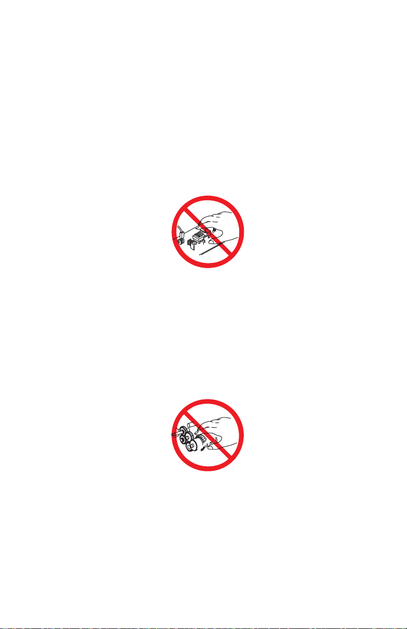
Servicing Electrical Components
Warning
Warning
Warning
Warning
2
3
Before starting any service procedure, switch off the printer power and unplug the
power cord from the wall outlet. If you must service the printer with power applied,
be aware of the potential for electrical shock.
Turning the power off by using the On/Off switch does not completely deenergize the printer. You must also disconnect the printer power cord from the
AC outlet. Position the power cord so that it is easily accessible during servicing.
Do not touch any electrical component unless you are instructed to do so by a
service procedure.
S7300-0
Servicing Mechanical Components
When servicing mechanical components within the printer, manually rotate drive
assemblies, rollers, and gears.
Do not try to manually rotate or manually stop the drive assemblies while any
printer motor is running.
S7300-0
Servicing Fuser Components
This printer uses heat to fuse the toner image to media. The Fuser Assembly is
VERY HOT. Turn the printer power off and wait at least 5 minutes for the Fuser
to cool before you attempt to service the Fuser Assembly or adjacent
components.
Service Manual ix
Page 9

Regulatory Specifications
Federal Communications Compliance
The equipment described in this manual generates and uses radio frequency energy. If
it is not installed properly in strict accordance with Xerox instructions, it m ay cause
interference with radio and television reception or may not function properly due to
interference from another device. However, there is no guarantee that interference
will not occur in a particular installation. If this equipment does cause harmful
interference to radio or television reception, which can be determined by turning the
equipment off and on, the user is encouraged to try to correct the interference by one
or more of the following measures:
■ Reorient or relocate the receiver (device being interfered with).
■ Increase the separation between the printer and the receiver.
■ Connect the printer into an outlet on a circuit different from that which the
receiver is connected.
■ Route the interface cables on the printer away from the receiver
■ Consult the dealer, Xerox service, or an experienced radio/television
technician for help.
Changes or modifications not expressly approved by Xerox can affect the emission
and immunity compliance and could void the user's authority to operate this product.
To ensure compliance, use shielded interface cables. A shielded parallel cable can be
purchased directly from Xerox at www.xerox.com/office/6250supplies
Xerox has tested this product to internationally accepted electromagnetic emission
and immunity standards. These standards are designed to mitigate interference caused
or received by this product in a normal office environment. This product is also
suitable for use in a residential environment based on the levels tested.
In the United States this product complies with the requirements of an unintentional
radiator in part 15 of the FCC rules. Operation is subject to the following two
conditions: (1) this device may not cause harmful interference; (2) this device must
accept any interference received, including interference that may cause undesired
operation.
This digital apparatus does not exceed the Class B limits for radio noise emissions
from digital apparatus set out in the Radio Interference Regulations of the Canadian
Department of Communications, ICES-003.
Le présent appareil numérique n'émet pas de bruits radioélectrique dépassant les
limits applicables aux appareils numériques de la classe B prescrites dans le
Réglement sur le brouillage radioélectrique édicté par le ministere des
Communications du Canada, NMB-003.
.
x Phaser 6250 Color Printer
Page 10

Declaration of Conformity
Xerox Corporation, declares, under our sole responsibility that the printer to which
this declaration relates, is in conformity with the following standards and other
normative documents:
In the European Union
following the provisions of the Low Voltage Directive 73/23/EEC and its
amendments:
EN 60950
(IEC 950)
"Safety of Information Technology Equipment including Electrical
Business Equipment"
following the provisions of the Electromagnetic Compatibility Directive 89/336/EEC
and its amendments:
EN55022:1998
(CISPR 22)
EN61000-3-2:1995
+A1:1998+A2:1998
(IEC61000-3-2)
EN61000-3-3:1995
(IEC61000-3-3)
EN55024:1998
(CISPR 24)
CISPR 24 Immunity
Phenomena Basic Standard Test Specification
Electrostatic Discharge IEC61000-4-2:1995 6kV Contact, 10kV Air
Radio-Frequency
Electromagnetic Field
(radiated)
Fast Burst Transients IEC61000-4-4:1995 5/50 Tr/Th ns, 5kHz Rep. Freq
Line Surge IEC61000-4-5:1995 Combination wave
Radio-Frequency
Electromagnetic Field
(Conducted)
Line voltage dips IEC61000-4-11:1994 >95% dip for ½ cycle @ 50 Hz
"Limits and Methods of measurement of radio interference
characteristics of Information Technology Equipment." Class B.
“Part 3: Limits - Section 2: Limits for harmonic current emissions
(equipment input current less than or equal to 16A per phase).”
“Part 3: Limits - Section 3: Limitation of voltage fluctuations and flicker
in low-voltage supply systems for equipment with rated current less
than or equal to 16A.”
"Information technology equipment - Immunity characteristics - Limits
and methods of measurement. "
IEC61000-4-3:1995 80-1000 MHz, 3V/m, 80% AM @ 1KHz
0.5kV on Signal Lines
1kV on AC Mains
2.0kV Common mode
2.0kV Differential mode
IEC61000-4-6:1996 0.15 - 80 MHz, 3V, 80% AM @ 1kHz
30% dip for 25 cycles @ 50 Hz
Service Manual xi
Page 11

CISPR 24 Immunity
Phenomena Basic Standard Test Specification
Line voltage drop-out IEC61000-4-11:1994 >95% dropout for 250 cycles @ 50 Hz
This product, if used properly in accordance with the user's instructions is neither
dangerous for the consumer nor for the environment. A signed copy of the
Declaration of Conformity for this product can be obtained from Xerox.
xii Phaser 6250 Color Printer
Page 12

Contents
Service Terms . . . . . . . . . . . . . . . . . . . . . . . . . . . . . . . . . . . . . . . . . . . . . . .iv
Symbols Marked on the Product . . . . . . . . . . . . . . . . . . . . . . . . . . . . . . . .v
Power Safety Precautions . . . . . . . . . . . . . . . . . . . . . . . . . . . . . . . . . . . . . .vi
Electrostatic Discharge (ESD) Precautions . . . . . . . . . . . . . . . . . . . . . . . . vii
Service Safety Summary . . . . . . . . . . . . . . . . . . . . . . . . . . . . . . . . . . . . . .viii
Regulatory Specifications . . . . . . . . . . . . . . . . . . . . . . . . . . . . . . . . . . . . . .x
1 General Information
Printer Introduction and Overview. . . . . . . . . . . . . . . . . . . . . . . . . . . . . . 1-2
Printer Configurations . . . . . . . . . . . . . . . . . . . . . . . . . . . . . . . . . . . . . . . 1-2
Printer Memory and RAM Capabilities . . . . . . . . . . . . . . . . . . . . . 1-4
Parts of the Printer . . . . . . . . . . . . . . . . . . . . . . . . . . . . . . . . . . . . . . . . . 1-5
Exterior. . . . . . . . . . . . . . . . . . . . . . . . . . . . . . . . . . . . . . . . . . . . . 1-5
Phaser 6250 Front Panel Configuration. . . . . . . . . . . . . . . . . . . . . . . . . . 1-6
Rear View . . . . . . . . . . . . . . . . . . . . . . . . . . . . . . . . . . . . . . . . . . 1-7
Image Processor Board. . . . . . . . . . . . . . . . . . . . . . . . . . . . . . . . . . . . . . 1-8
Routine Maintenance Items. . . . . . . . . . . . . . . . . . . . . . . . . . . . . . . . . . . 1-9
Consumables. . . . . . . . . . . . . . . . . . . . . . . . . . . . . . . . . . . . . . . . . . . . . . 1-9
Consumable Life Counter Behavior . . . . . . . . . . . . . . . . . . . . . . 1-10
Printer Specifications. . . . . . . . . . . . . . . . . . . . . . . . . . . . . . . . . . . . . . . 1-11
Physical Dimensions and Clearances. . . . . . . . . . . . . . . . . . . . . 1-11
Functional Specifications . . . . . . . . . . . . . . . . . . . . . . . . . . . . . . 1-12
Electrical Specifications . . . . . . . . . . . . . . . . . . . . . . . . . . . . . . . 1-13
Environmental Specifications. . . . . . . . . . . . . . . . . . . . . . . . . . . 1-13
Media and Tray Specifications . . . . . . . . . . . . . . . . . . . . . . . . . . 1-14
2 Theory of Operation
Overview of the Phaser 6250 Color Laser Printer Theory of Operation . . 2-2
Summary of the Printing Process . . . . . . . . . . . . . . . . . . . . . . . . 2-2
Print Modes . . . . . . . . . . . . . . . . . . . . . . . . . . . . . . . . . . . . . . . . . 2-5
Printer Controls. . . . . . . . . . . . . . . . . . . . . . . . . . . . . . . . . . . . . . . . . . . . 2-5
Paper Size Control . . . . . . . . . . . . . . . . . . . . . . . . . . . . . . . . . . . . 2-5
Selective Control; Paper Pick . . . . . . . . . . . . . . . . . . . . . . . . . . . . 2-6
Laser Light Intensity Control . . . . . . . . . . . . . . . . . . . . . . . . . . . . 2-6
Process Control . . . . . . . . . . . . . . . . . . . . . . . . . . . . . . . . . . . . . . 2-6
LED Light Density CTD (ADC) Control of Sensor . . . . . . . . . . . . . 2-8
Color Registration Control . . . . . . . . . . . . . . . . . . . . . . . . . . . . . . 2-9
Transfer Roller Assembly Control. . . . . . . . . . . . . . . . . . . . . . . . 2-11
Toner Control. . . . . . . . . . . . . . . . . . . . . . . . . . . . . . . . . . . . . . . 2-12
Fuser Control . . . . . . . . . . . . . . . . . . . . . . . . . . . . . . . . . . . . . . . 2-13
Paper Path of the Printer . . . . . . . . . . . . . . . . . . . . . . . . . . . . . . . . . . . . 2-14
Paper Path Route. . . . . . . . . . . . . . . . . . . . . . . . . . . . . . . . . . . . 2-15
Service Manual xiii
Page 13

Major Assemblies and Functions. . . . . . . . . . . . . . . . . . . . . . . . . . . . . . 2-16
Frame and Drive Assemblies . . . . . . . . . . . . . . . . . . . . . . . . . . . 2-16
Main Drive Assembly - Transmission Route . . . . . . . . . . . . . . . 2-17
Gear Layout - Print Engine and Tray 1. . . . . . . . . . . . . . . . . . . . 2-18
Paper Tray 2 . . . . . . . . . . . . . . . . . . . . . . . . . . . . . . . . . . . . . . . 2-19
Paper Feed - Tray 2 . . . . . . . . . . . . . . . . . . . . . . . . . . . . . . . . . . 2-20
HCF Drive and Gears - Transmission Route. . . . . . . . . . . . . . . . 2-25
500-Sheet Feeder Drive and Gears - Transmission Route . . . . . 2-26
Retard Housing Assembly . . . . . . . . . . . . . . . . . . . . . . . . . . . . . 2-27
Chute Assembly In. . . . . . . . . . . . . . . . . . . . . . . . . . . . . . . . . . . 2-28
Chute Assembly Out . . . . . . . . . . . . . . . . . . . . . . . . . . . . . . . . . 2-29
Chute Assembly Exit . . . . . . . . . . . . . . . . . . . . . . . . . . . . . . . . . 2-30
Duplex Motor Drive and Gear - Transmission Route . . . . . . . . . 2-31
Chute Assembly Registration (REGI). . . . . . . . . . . . . . . . . . . . . 2-32
Transfer Roller and Fuser Assembly . . . . . . . . . . . . . . . . . . . . . 2-33
Fuser Drive Assembly - Transmission Route. . . . . . . . . . . . . . . 2-34
Xerographics . . . . . . . . . . . . . . . . . . . . . . . . . . . . . . . . . . . . . . . 2-35
Imaging Unit Charge Voltage Contacts . . . . . . . . . . . . . . . . . . . 2-36
Toner Cartridge Assembly . . . . . . . . . . . . . . . . . . . . . . . . . . . . . 2-38
Toner Cartridge Assembly - cont’d . . . . . . . . . . . . . . . . . . . . . . 2-39
Toner Motor Drive Assembly - Transmission Route . . . . . . . . . 2-40
Developer Assembly Transmission Route . . . . . . . . . . . . . . . . . 2-40
3 Error Messages and Codes
Introduction. . . . . . . . . . . . . . . . . . . . . . . . . . . . . . . . . . . . . . . . . . . . . . . 3-2
Servicing Instructions . . . . . . . . . . . . . . . . . . . . . . . . . . . . . . . . . . . . . . . 3-3
Using the Troubleshooting Procedures . . . . . . . . . . . . . . . . . . . . 3-4
General Notes on Troubleshooting. . . . . . . . . . . . . . . . . . . . . . . . 3-4
Voltage Measurements . . . . . . . . . . . . . . . . . . . . . . . . . . . . . . . . 3-5
Service Diagnostics. . . . . . . . . . . . . . . . . . . . . . . . . . . . . . . . . . . . . . . . . 3-6
Service Diagnostic Front Panel Button Descriptions . . . . . . . . . . 3-7
Diagnostic Menu Map . . . . . . . . . . . . . . . . . . . . . . . . . . . . . . . . . 3-8
Service Diagnostic Tests . . . . . . . . . . . . . . . . . . . . . . . . . . . . . . . 3-9
Jam History Error Codes Table . . . . . . . . . . . . . . . . . . . . . . . . . 3-16
Error Messages and Codes Summary Table . . . . . . . . . . . . . . . 3-17
Jam Errors. . . . . . . . . . . . . . . . . . . . . . . . . . . . . . . . . . . . . . . . . . . . . . . 3-19
Jam at Fuser: Jam F. . . . . . . . . . . . . . . . . . . . . . . . . . . . . . . . . . 3-19
Jam at Duplex: Jam D . . . . . . . . . . . . . . . . . . . . . . . . . . . . . . . . 3-21
Jam at Registration Roller: Jam RR. . . . . . . . . . . . . . . . . . . . . . 3-23
Misfeed at Tray 1 (MPT): Jam T1. . . . . . . . . . . . . . . . . . . . . . . . 3-25
Misfeed at Tray 2: Jam T2 . . . . . . . . . . . . . . . . . . . . . . . . . . . . . 3-28
Misfeed at Tray 3: Jam T3 . . . . . . . . . . . . . . . . . . . . . . . . . . . . . 3-31
Misfeed at Tray 4: Jam T4 . . . . . . . . . . . . . . . . . . . . . . . . . . . . . 3-34
Door and Cover Errors. . . . . . . . . . . . . . . . . . . . . . . . . . . . . . . . . . . . . . 3-36
Close Front Door . . . . . . . . . . . . . . . . . . . . . . . . . . . . . . . . . . . . 3-36
Consumable Errors . . . . . . . . . . . . . . . . . . . . . . . . . . . . . . . . . . . . . . . . 3-37
xiv Phaser 6250 Color Printer
Page 14

Install or Reseat Imaging Unit . . . . . . . . . . . . . . . . . . . . . . . . . . 3-37
Replace Imaging Unit or
Imaging Unit is Near End of Life. . . . . . . . . . . . . . . . . . . . . . 3-38
Install or Reseat Transfer Roller. . . . . . . . . . . . . . . . . . . . . . . . . 3-39
Replace Transfer Roller or
Transfer Roller is at End of Life . . . . . . . . . . . . . . . . . . . . . . 3-40
Install or Reseat Fuser . . . . . . . . . . . . . . . . . . . . . . . . . . . . . . . . 3-41
Replace Fuser or Fuser is Near End of Life. . . . . . . . . . . . . . . . . 3-42
Install or Lock [Y] [M] [C] [K] Toner Cartridge . . . . . . . . . . . . . 3-43
Replace [Y] [M] [C] [K]Toner Cartridge or
[Y] [M] [C] [K] Toner Is Low . . . . . . . . . . . . . . . . . . . . . . . . 3-45
Dusty Density Sensor. . . . . . . . . . . . . . . . . . . . . . . . . . . . . . . . . 3-47
Output Tray is Full, Unload Paper. . . . . . . . . . . . . . . . . . . . . . . . 3-48
Remove Ribbon from [Y] [M] [C] [K] Toner Cartridge. . . . . . . . 3-49
Tray and Media Errors. . . . . . . . . . . . . . . . . . . . . . . . . . . . . . . . . . . . . . 3-50
Insert Tray [2] or Tray [2] Missing. . . . . . . . . . . . . . . . . . . . . . . 3-50
Insert Tray [3] [4] or Tray [3] [4] Missing . . . . . . . . . . . . . . . . . 3-52
Tray 2 Paper is Low . . . . . . . . . . . . . . . . . . . . . . . . . . . . . . . . . . 3-54
Tray [3] [4] Paper is Low. . . . . . . . . . . . . . . . . . . . . . . . . . . . . . 3-55
Out of Paper; Load Tray 1 (MPT) with [size] [type] . . . . . . . . . . 3-56
Out of Paper; Load Tray [2] [3] [4] with [size] [type]. . . . . . . . . 3-57
Wrong Paper Size; Load Tray 2 with [size] [type] . . . . . . . . . . . 3-58
Wrong Paper Size; Load Tray [3] [4] with [size] [type] . . . . . . . 3-60
Wrong Paper Type; Load Tray [1 (MPT)] [2] [3] [4]
with [size] [type] . . . . . . . . . . . . . . . . . . . . . . . . . . . . . . . . . 3-62
Fatal Errors . . . . . . . . . . . . . . . . . . . . . . . . . . . . . . . . . . . . . . . . . . . . . . 3-63
Laser Failure. . . . . . . . . . . . . . . . . . . . . . . . . . . . . . . . . . . . . . . . 3-63
Density Sensor Failure . . . . . . . . . . . . . . . . . . . . . . . . . . . . . . . . 3-64
Fuser Failure. . . . . . . . . . . . . . . . . . . . . . . . . . . . . . . . . . . . . . . . 3-65
Fuser Failure (cont’d). . . . . . . . . . . . . . . . . . . . . . . . . . . . . . . . . 3-66
Fuser Failure (cont’d). . . . . . . . . . . . . . . . . . . . . . . . . . . . . . . . . 3-67
Fuser Fan Failure . . . . . . . . . . . . . . . . . . . . . . . . . . . . . . . . . . . . 3-68
Rear Fan Failure . . . . . . . . . . . . . . . . . . . . . . . . . . . . . . . . . . . . . 3-69
Generic Fan Failure. . . . . . . . . . . . . . . . . . . . . . . . . . . . . . . . . . . 3-70
Engine Firmware Failure. . . . . . . . . . . . . . . . . . . . . . . . . . . . . . . 3-71
Imaging Unit Firmware Failure. . . . . . . . . . . . . . . . . . . . . . . . . . 3-72
Fuser Firmware Failure. . . . . . . . . . . . . . . . . . . . . . . . . . . . . . . . 3-73
Controller to Engine Communications Failure . . . . . . . . . . . . . . 3-74
Engine NVRAM Error . . . . . . . . . . . . . . . . . . . . . . . . . . . . . . . . . 3-75
Replace [Y] [M] [C] [K] Toner Cartridge . . . . . . . . . . . . . . . . . . 3-76
[Y] [M] [C] [K] Toner Cartridge Failure . . . . . . . . . . . . . . . . . . . 3-77
Non-Phaser 6250 Fuser . . . . . . . . . . . . . . . . . . . . . . . . . . . . . . . 3-78
Non-Phaser 6250 Imaging Unit . . . . . . . . . . . . . . . . . . . . . . . . . 3-79
Environmental Sensor Failure. . . . . . . . . . . . . . . . . . . . . . . . . . . 3-80
Service Manual xv
Page 15

4 General Troubleshooting
Introduction. . . . . . . . . . . . . . . . . . . . . . . . . . . . . . . . . . . . . . . . . . . . . . . 4-2
Printer Status Page . . . . . . . . . . . . . . . . . . . . . . . . . . . . . . . . . . . 4-2
Power-Up Modes. . . . . . . . . . . . . . . . . . . . . . . . . . . . . . . . . . . . . 4-2
System Start-Up and POST. . . . . . . . . . . . . . . . . . . . . . . . . . . . . . . . . . . 4-3
System Boot Sequence . . . . . . . . . . . . . . . . . . . . . . . . . . . . . . . . 4-3
Power On Self Test (POST) . . . . . . . . . . . . . . . . . . . . . . . . . . . . . 4-4
POST Faults. . . . . . . . . . . . . . . . . . . . . . . . . . . . . . . . . . . . . . . . . 4-6
LED Blink Patterns. . . . . . . . . . . . . . . . . . . . . . . . . . . . . . . . . . . . 4-6
POST Diagnostic Test Descriptions . . . . . . . . . . . . . . . . . . . . . . . 4-7
Front Panel Troubleshooting. . . . . . . . . . . . . . . . . . . . . . . . . . . . . . . . . . 4-8
No Front Panel Display after Power is Turned ON . . . . . . . . . . . . 4-8
Front Panel LED is on, Front Panel Display is Blank. . . . . . . . . . . 4-8
Front Panel Continually Displays “Warming Up...”. . . . . . . . . . . . 4-8
Front Panel Continually Displays "Install or Reseat Imaging Unit" 4-8
Fault Isolation . . . . . . . . . . . . . . . . . . . . . . . . . . . . . . . . . . . . . . . . . . . . . 4-9
Inoperable Printer Troubleshooting. . . . . . . . . . . . . . . . . . . . . . . . . . . . . 4-9
Engine Power-Up Sequence. . . . . . . . . . . . . . . . . . . . . . . . . . . . . 4-9
Printer Does Not Come to a "Ready" State . . . . . . . . . . . . . . . . . . 4-9
Paper Size Switch Assembly . . . . . . . . . . . . . . . . . . . . . . . . . . . . . . . . . 4-10
Power Supply . . . . . . . . . . . . . . . . . . . . . . . . . . . . . . . . . . . . . . . . . . . . 4-10
AC Power Supply Troubleshooting . . . . . . . . . . . . . . . . . . . . . . . . . . . 4-11
DC Power Supply Troubleshooting . . . . . . . . . . . . . . . . . . . . . . . . . . . . 4-12
Media Jams and the Paper Path . . . . . . . . . . . . . . . . . . . . . . . . . . . . . . 4-14
Operating System and Application Problems . . . . . . . . . . . . . . . . . . . . 4-17
Macintosh printing problems. . . . . . . . . . . . . . . . . . . . . . . . . . . 4-17
Windows printing problems. . . . . . . . . . . . . . . . . . . . . . . . . . . . 4-19
Network Problems. . . . . . . . . . . . . . . . . . . . . . . . . . . . . . . . . . . . . . . . . 4-19
5 Print-Quality Troubleshooting
Print-Quality Problems Overview. . . . . . . . . . . . . . . . . . . . . . . . . . . . . . . 5-2
Defects Associated with Specific Printer Components. . . . . . . . . 5-3
Front Panel Test Prints . . . . . . . . . . . . . . . . . . . . . . . . . . . . . . . . . . . . . . 5-4
Test Print 1: CMYK Sample Page. . . . . . . . . . . . . . . . . . . . . . . . . 5-4
Test Print 2: RGB Test Print. . . . . . . . . . . . . . . . . . . . . . . . . . . . . 5-5
Service Test Prints . . . . . . . . . . . . . . . . . . . . . . . . . . . . . . . . . . . . . . . . . 5-6
Test Print 3: Test Pattern Sample . . . . . . . . . . . . . . . . . . . . . . . . 5-6
600 x 600 Service Test Print . . . . . . . . . . . . . . . . . . . . . . . . . . . . 5-8
Print Engine Test Print. . . . . . . . . . . . . . . . . . . . . . . . . . . . . . . . . . . . . . . 5-9
Print-Quality Troubleshooting . . . . . . . . . . . . . . . . . . . . . . . . . . . . . . . . 5-10
Light Prints . . . . . . . . . . . . . . . . . . . . . . . . . . . . . . . . . . . . . . . . 5-10
Light Print in Only One Color. . . . . . . . . . . . . . . . . . . . . . . . . . . 5-11
Blank Prints . . . . . . . . . . . . . . . . . . . . . . . . . . . . . . . . . . . . . . . . 5-13
Black Prints with White Margin Border . . . . . . . . . . . . . . . . . . . 5-14
Solid Dark or Dirty Prints, No Border. . . . . . . . . . . . . . . . . . . . . 5-15
xvi Phaser 6250 Color Printer
Page 16

Missing Band, Voids Or Streaks In a Single Color
or All Colors Parallel to the Leading Edge. . . . . . . . . . . . . . . 5-16
Missing Band, Voids or Streaks in a Single Color
or All Colors in Direction of Paper Travel . . . . . . . . . . . . . . . 5-18
Repeating and/or Random Spots . . . . . . . . . . . . . . . . . . . . . . . . 5-19
Background Contamination . . . . . . . . . . . . . . . . . . . . . . . . . . . . 5-20
Residual Image, Ghosting or Hot Offset. . . . . . . . . . . . . . . . . . . 5-22
Incomplete Fusing or Cold Offset. . . . . . . . . . . . . . . . . . . . . . . . 5-23
Mis-Registration, Color Layer not Correctly Registered
in the Process Direction . . . . . . . . . . . . . . . . . . . . . . . . . . . . 5-24
Dirty Vertical Streaks on the Edges of the Page . . . . . . . . . . . . . 5-25
6 Adjustments and Calibrations
Calibrations . . . . . . . . . . . . . . . . . . . . . . . . . . . . . . . . . . . . . . . . . . . . . . . 6-2
Color Calibration. . . . . . . . . . . . . . . . . . . . . . . . . . . . . . . . . . . . . . 6-2
Margin Calibration . . . . . . . . . . . . . . . . . . . . . . . . . . . . . . . . . . . . 6-2
Adjustments. . . . . . . . . . . . . . . . . . . . . . . . . . . . . . . . . . . . . . . . . . . . . . . 6-3
Horizontal and Vertical Color Registration . . . . . . . . . . . . . . . . . . 6-3
Resetting NVRAM . . . . . . . . . . . . . . . . . . . . . . . . . . . . . . . . . . . . . . . . . . 6-4
PostScript NVRAM Resets. . . . . . . . . . . . . . . . . . . . . . . . . . . . . . 6-4
Service Diagnostics PostScript NVRAM Resets. . . . . . . . . . . . . . . . . . . . 6-8
7 Cleaning and Maintenance
Service Preventive Maintenance Procedure. . . . . . . . . . . . . . . . . . . . . . . 7-2
Cleaning . . . . . . . . . . . . . . . . . . . . . . . . . . . . . . . . . . . . . . . . . . . . . . . . . . 7-2
8 Service Part Disassembly
Overview . . . . . . . . . . . . . . . . . . . . . . . . . . . . . . . . . . . . . . . . . . . . . . . . . 8-2
Standard Orientation of the Printer. . . . . . . . . . . . . . . . . . . . . . . . 8-2
General Notes on Disassembly . . . . . . . . . . . . . . . . . . . . . . . . . . . . . . . . 8-3
Preparation. . . . . . . . . . . . . . . . . . . . . . . . . . . . . . . . . . . . . . . . . . 8-3
Notations in the Disassembly Text. . . . . . . . . . . . . . . . . . . . . . . . 8-3
Removing Routine Maintenance Items and Consumables. . . . . . . . . . . . 8-4
Transfer Roller Removal. . . . . . . . . . . . . . . . . . . . . . . . . . . . . . . . 8-4
Imaging Unit Removal . . . . . . . . . . . . . . . . . . . . . . . . . . . . . . . . . 8-4
Fuser Removal. . . . . . . . . . . . . . . . . . . . . . . . . . . . . . . . . . . . . . . 8-4
Toner Cartridge Removal . . . . . . . . . . . . . . . . . . . . . . . . . . . . . . . 8-5
Print Engine Disassembly . . . . . . . . . . . . . . . . . . . . . . . . . . . . . . . . . . . . 8-6
Covers . . . . . . . . . . . . . . . . . . . . . . . . . . . . . . . . . . . . . . . . . . . . . . . . . . . 8-6
Front Cover (PL 1.1.2) . . . . . . . . . . . . . . . . . . . . . . . . . . . . . . . . . 8-6
Front Panel (PL 1.1.1) . . . . . . . . . . . . . . . . . . . . . . . . . . . . . . . . . 8-7
Fuser Fan (PL 1.1.7). . . . . . . . . . . . . . . . . . . . . . . . . . . . . . . . . . . 8-8
Top Main Cover (PL1.1.9) . . . . . . . . . . . . . . . . . . . . . . . . . . . . . . 8-9
Image Unit Top Cover (Door C) (PL1.1.10) . . . . . . . . . . . . . . . . 8-10
Right and Left Side Covers (PL1.1.24), (PL1.1.30) . . . . . . . . . . 8-11
Service Manual xvii
Page 17

Rear Cover (PL 1.1.20) . . . . . . . . . . . . . . . . . . . . . . . . . . . . . . . 8-12
Left and Right Links (PL 1.1.23) . . . . . . . . . . . . . . . . . . . . . . . . 8-13
Tray 1 (MPT) (PL1.1.99) . . . . . . . . . . . . . . . . . . . . . . . . . . . . . . 8-14
Front Right Cover (PL 1.1.25) . . . . . . . . . . . . . . . . . . . . . . . . . . 8-15
Front Left Cover Assembly (PL1.1.29). . . . . . . . . . . . . . . . . . . . 8-16
Paper Feed. . . . . . . . . . . . . . . . . . . . . . . . . . . . . . . . . . . . . . . . . . . . . . . 8-18
Paper Feed Roller (PL 2.1.2) (Routine Maintenance Item). . . . . 8-18
Turn Chute Assembly (PL3.1.2). . . . . . . . . . . . . . . . . . . . . . . . . 8-19
Printer Chassis/Feeder Assembly. . . . . . . . . . . . . . . . . . . . . . . . 8-20
Paper Pick Assembly (PL3.3.1) . . . . . . . . . . . . . . . . . . . . . . . . . 8-22
Right and Left Housing (PL 3.2) . . . . . . . . . . . . . . . . . . . . . . . . 8-23
Temperature/Humidity Harness (PL3.2.1) and Sensor (PL3.2.2) 8-24
High-Capacity Feeder Harness (PL3.2.3). . . . . . . . . . . . . . . . . . 8-25
Paper Size Switch Assembly (PL3.2.4) . . . . . . . . . . . . . . . . . . . 8-26
Low Paper Lever (PL3.2.7), Indicator (PL3.2.8) and
Indicator Guide (PL3.2.10). . . . . . . . . . . . . . . . . . . . . . . . . . 8-27
Paper Pick Rollers (PL3.3.3) . . . . . . . . . . . . . . . . . . . . . . . . . . . 8-29
No Paper Actuator (PL3.3.5), No/Low Paper Sensor (PL3.3.4) . 8-30
Link Actuator (PL3.3.6) . . . . . . . . . . . . . . . . . . . . . . . . . . . . . . . 8-32
Feed Solenoid (PL3.3.17) . . . . . . . . . . . . . . . . . . . . . . . . . . . . . 8-33
Turn Clutch Assembly (PL3.3.18) . . . . . . . . . . . . . . . . . . . . . . . 8-34
Roll Turn Assembly (PL3.3.20) . . . . . . . . . . . . . . . . . . . . . . . . . 8-35
Paper Feed Roller (Routine Maintenance Item) . . . . . . . . . . . . . 8-36
Retard Roller Housing Assembly (PL4.1.1). . . . . . . . . . . . . . . . 8-37
Turn Roll (PL 4.1.2), Turn Clutch (PL 4.1.9),
and Friction Clutch Assembly (PL 4.1.4) . . . . . . . . . . . . . . . 8-38
Retard Roller Assembly (PL4.1.5) . . . . . . . . . . . . . . . . . . . . . . . 8-39
Chute Assembly In . . . . . . . . . . . . . . . . . . . . . . . . . . . . . . . . . . . . . . . . 8-41
Chute Assembly In (PL 5.1.1) . . . . . . . . . . . . . . . . . . . . . . . . . . 8-41
CTD (ADC) Sensor (PL 5.1.11) . . . . . . . . . . . . . . . . . . . . . . . . . 8-42
Toner Full Sensor (PL 5.1.13) . . . . . . . . . . . . . . . . . . . . . . . . . . 8-43
Fuser Drive Assembly (PL 5.1.18) . . . . . . . . . . . . . . . . . . . . . . . 8-44
Right Latch (Door A) (PL 5.1.21). . . . . . . . . . . . . . . . . . . . . . . . 8-45
Left Latch (PL 5.1.30) . . . . . . . . . . . . . . . . . . . . . . . . . . . . . . . . 8-46
Chute Assembly Out . . . . . . . . . . . . . . . . . . . . . . . . . . . . . . . . . . . . . . . 8-47
Chute Assembly Out (PL6.1.1). . . . . . . . . . . . . . . . . . . . . . . . . . 8-47
Output Tray Full Actuator (PL 6.1.5) and
Full Stack Sensor (PL 6.1.4). . . . . . . . . . . . . . . . . . . . . . . . . 8-50
Duplex Actuator (PL 6.1.13) and Duplex Sensor (PL 6.1.4). . . . 8-51
Tray 1 Actuator (PL 6.1.37) and Tray 1 Sensor (PL 6.1.4). . . . . 8-53
Static Eliminator Assembly (PL 6.1.9). . . . . . . . . . . . . . . . . . . . 8-55
Duplex Roller (PL 6.1.12) . . . . . . . . . . . . . . . . . . . . . . . . . . . . . 8-56
Latch Plate (PL 6.1.17), Latch Out (PL 6.1.18),
Latch Holder (PL 6.1.19), and Latch Spring Out (PL 6.1.20) 8-57
Tray 1 Paper Pick Assembly (PL 6.1.27) (Roll Feed). . . . . . . . . 8-58
Tray 1 Feed Solenoid (PL 6.1.40). . . . . . . . . . . . . . . . . . . . . . . . 8-59
xviii Phaser 6250 Color Printer
Page 18

Tray 1 Shaft (PL 6.1.28). . . . . . . . . . . . . . . . . . . . . . . . . . . . . . . 8-60
Tray 1 Bottom Plate (PL 6.1.42). . . . . . . . . . . . . . . . . . . . . . . . . 8-61
Chute Assembly Exit . . . . . . . . . . . . . . . . . . . . . . . . . . . . . . . . . . . . . . . 8-62
Chute Assembly Exit (PL 7.1.1) . . . . . . . . . . . . . . . . . . . . . . . . . 8-62
Exit Roller (PL 7.1.4) . . . . . . . . . . . . . . . . . . . . . . . . . . . . . . . . . 8-63
Mid Roller (PL 7.1.5) . . . . . . . . . . . . . . . . . . . . . . . . . . . . . . . . . 8-64
Duplex Motor Assembly (PL 7.1.8) . . . . . . . . . . . . . . . . . . . . . . 8-65
Exit Actuator (Fuser) (PL 8.1.7) . . . . . . . . . . . . . . . . . . . . . . . . . 8-66
Strap (PL 8.1.13) . . . . . . . . . . . . . . . . . . . . . . . . . . . . . . . . . . . . 8-67
Xerographics . . . . . . . . . . . . . . . . . . . . . . . . . . . . . . . . . . . . . . . . . . . . . 8-68
Laser Unit (PL 9.1.1) . . . . . . . . . . . . . . . . . . . . . . . . . . . . . . . . . 8-68
Housing Assembly Bias (PL 9.1.4). . . . . . . . . . . . . . . . . . . . . . . 8-69
Chute Assembly Registration (PL 9.1.6) and
Housing Assembly Electric (PL 9.1.11) . . . . . . . . . . . . . . . . 8-71
Registration Sensor Actuator (PL 9.1.9) and
Registration Sensor (PL 9.1.8). . . . . . . . . . . . . . . . . . . . . . . 8-73
OHP Sensor and Harness (Kit) (PL 9.1.12) . . . . . . . . . . . . . . . . 8-75
Toner Cartridge Holder Assemblies . . . . . . . . . . . . . . . . . . . . . . . . . . . . 8-77
Toner Cartridge Holder Unit Assembly (PL 10.1). . . . . . . . . . . . 8-77
Toner Cartridge Holder Assembly. . . . . . . . . . . . . . . . . . . . . . . . 8-80
Toner Present Switch Bracket and Actuator
(PL 10.1.6 and 10.1.22). . . . . . . . . . . . . . . . . . . . . . . . . . . . 8-82
Toner Low Sensor (PL 10.1.5). . . . . . . . . . . . . . . . . . . . . . . . . . 8-84
CRUM Reader Box Assembly (PL 10.1.21) . . . . . . . . . . . . . . . . 8-85
EEPROM Board (PL 10.1.14). . . . . . . . . . . . . . . . . . . . . . . . . . . 8-86
Sub-High Voltage Power Supply Board (PL 10.1.15). . . . . . . . . 8-87
Frame and Drive Assemblies . . . . . . . . . . . . . . . . . . . . . . . . . . . . . . . . . 8-88
Left Lever Plate (PL 11.1.1), Lever Bracket (PL 11.1.2),
Lever Link (PL 11.1.3), Lever Drum (PL 11.1.4), and
Lever Spring (PL 11.1.5) . . . . . . . . . . . . . . . . . . . . . . . . . . . 8-88
Lever Plate Right (PL 11.1.7), Lever Bracket (PL 11.1.2),
Lever Link (PL 11.1.6), Lever Drum (PL 11.1.4), and
Lever Spring (PL 11.1.5) . . . . . . . . . . . . . . . . . . . . . . . . . . . 8-91
Main Drive Assembly (PL 11.1.14). . . . . . . . . . . . . . . . . . . . . . . 8-94
Developer Drive Assembly (PL 11.1.13). . . . . . . . . . . . . . . . . . . 8-95
Actuator, I/L (PL 11.1.8) and Spring, I/L (PL 11.1.9). . . . . . . . . 8-96
Earth Ground Circuit Board (PL 11.1.16) . . . . . . . . . . . . . . . . . . 8-97
Electrical . . . . . . . . . . . . . . . . . . . . . . . . . . . . . . . . . . . . . . . . . . . . . . . . 8-98
AC Switch Harness Assembly (PL 12.1.11) . . . . . . . . . . . . . . . . 8-98
Low-Voltage Power Supply (PL 12.1.10) . . . . . . . . . . . . . . . . . . 8-99
Motor Driver Board (PL 12.1.12) . . . . . . . . . . . . . . . . . . . . . . . 8-101
Rear Fan (PL 12.1.2) . . . . . . . . . . . . . . . . . . . . . . . . . . . . . . . . 8-102
Card Cage. . . . . . . . . . . . . . . . . . . . . . . . . . . . . . . . . . . . . . . . . 8-103
Housing Assembly Contact (PL 12.1.14) . . . . . . . . . . . . . . . . . 8-106
Engine Control Circuit Board (PL12.1.1) . . . . . . . . . . . . . . . . . 8-107
Image Processor Board (PL12.1.4) . . . . . . . . . . . . . . . . . . . . . 8-110
Service Manual xix
Page 19

Optional High Capacity Feeder Disassembly . . . . . . . . . . . . . . . . . . . . 8-111
Cover Front (PL14.2.4) . . . . . . . . . . . . . . . . . . . . . . . . . . . . . . 8-111
Cover, Right (PL14.2.1) and Cover, Left (PL14.2.3) . . . . . . . . 8-112
Turn Chute Assembly (PL14.3.7) . . . . . . . . . . . . . . . . . . . . . . . 8-113
Tray 3 Harness Assembly (PL14.5.3), Tray 4 Harness Assembly
(PL14.5.4), and HCF Plug Harness Assembly (PL14.5.2) . 8-114
Circuit Board, HCF (PL14.5.1) . . . . . . . . . . . . . . . . . . . . . . . . . 8-116
Drive Feeder Assembly (PL14.5.5). . . . . . . . . . . . . . . . . . . . . . 8-117
Indicator Assembly (PL14.5.9) . . . . . . . . . . . . . . . . . . . . . . . . 8-118
Right Tray Guide (PL14.3.5)and Low Paper Lever (PL 14.5.8) 8-119
Left Tray Guide (PL14.3.3). . . . . . . . . . . . . . . . . . . . . . . . . . . . 8-122
Link Actuator (PL 14.4.6). . . . . . . . . . . . . . . . . . . . . . . . . . . . . 8-124
HCF Paper Pick Assembly (PL14.4.1) . . . . . . . . . . . . . . . . . . . 8-125
Idler Gear (PL14.5.6). . . . . . . . . . . . . . . . . . . . . . . . . . . . . . . . 8-126
No Paper, Low Paper Sensor (PL14.5.7). . . . . . . . . . . . . . . . . 8-127
Paper Size Switch Assembly (PL14.3.6) . . . . . . . . . . . . . . . . . 8-128
Casters, Locking (PL 14.2.5)/Non-Locking (PL 14.2.6) . . . . . . 8-129
Optional 500-sheet Feeder Disassembly . . . . . . . . . . . . . . . . . . . . . . . 8-130
Cover Front (PL15.2.4) . . . . . . . . . . . . . . . . . . . . . . . . . . . . . . 8-130
Cover, Right (PL15.2.2) and Cover, Left (PL15.2.1) . . . . . . . . 8-131
Turn Chute Assembly (PL15.3.9) . . . . . . . . . . . . . . . . . . . . . . . 8-132
Tray 3 Harness Assembly (PL15.5.3) and
STF Plug Harness Assembly (PL15.5.2). . . . . . . . . . . . . . . 8-133
Circuit Board, STF (PL15.5.1) . . . . . . . . . . . . . . . . . . . . . . . . . 8-135
Drive Feeder Assembly (PL15.5.5). . . . . . . . . . . . . . . . . . . . . . 8-136
Indicator Assembly (PL15.5.8) . . . . . . . . . . . . . . . . . . . . . . . . 8-137
Right Tray Guide (PL15.3.5)and Low Paper Lever (PL 15.5.7) 8-138
Left Tray Guide (PL15.3.3). . . . . . . . . . . . . . . . . . . . . . . . . . . . 8-141
Link Actuator (PL 15.4.6). . . . . . . . . . . . . . . . . . . . . . . . . . . . . 8-143
STF Paper Pick Assembly (PL15.4.1) . . . . . . . . . . . . . . . . . . . 8-144
No Paper, Low Paper Sensor (PL15.5.6). . . . . . . . . . . . . . . . . 8-145
Paper Size Switch Assembly (PL15.3.6) . . . . . . . . . . . . . . . . . 8-146
9 Parts List
Serial Number Format. . . . . . . . . . . . . . . . . . . . . . . . . . . . . . . . . . . . . . . 9-2
Using the Parts List. . . . . . . . . . . . . . . . . . . . . . . . . . . . . . . . . . . . . . . . . 9-3
Print Engine Parts . . . . . . . . . . . . . . . . . . . . . . . . . . . . . . . . . . . . . . . . . . 9-4
PL 1.1 Covers . . . . . . . . . . . . . . . . . . . . . . . . . . . . . . . . . . . . . . . 9-4
PL 2.1 Universal Paper Tray. . . . . . . . . . . . . . . . . . . . . . . . . . . . . 9-7
PL 3.1 Paper Feed I . . . . . . . . . . . . . . . . . . . . . . . . . . . . . . . . . . . 9-8
PL 3.2 Paper Feed II. . . . . . . . . . . . . . . . . . . . . . . . . . . . . . . . . . 9-10
PL 3.3 Paper Feed III . . . . . . . . . . . . . . . . . . . . . . . . . . . . . . . . . 9-12
PL 4.1 Housing Assembly Retard . . . . . . . . . . . . . . . . . . . . . . . 9-14
PL 5.1 Chute Assembly In . . . . . . . . . . . . . . . . . . . . . . . . . . . . . 9-16
PL 6.1 Chute Assembly Out. . . . . . . . . . . . . . . . . . . . . . . . . . . . 9-18
. . . . . . . . . . . . . . . . . . . . . . . . . . . . . . . . . . . . . . . . . . . . . . . . . 9-21
xx Phaser 6250 Color Printer
Page 20

PL 7.1 Chute Assembly Exit . . . . . . . . . . . . . . . . . . . . . . . . . . . . 9-22
PL 8.1 Transfer Roller & Fuser Assembly (RMIs) . . . . . . . . . . . 9-24
PL 9.1 Xerographics. . . . . . . . . . . . . . . . . . . . . . . . . . . . . . . . . . 9-26
PL 10.1 Holder Toner Cartridge Assembly . . . . . . . . . . . . . . . . . 9-28
PL 11.1 Frame and Drive Assemblies. . . . . . . . . . . . . . . . . . . . . 9-30
PL 12.1 Electrical . . . . . . . . . . . . . . . . . . . . . . . . . . . . . . . . . . . . 9-32
PL 13.1 Harness Assemblies. . . . . . . . . . . . . . . . . . . . . . . . . . . . . . . . . 9-34
Optional High-Capacity Feeder. . . . . . . . . . . . . . . . . . . . . . . . . . . . . . . . 9-36
PL 14.1 Paper Trays 3 & 4. . . . . . . . . . . . . . . . . . . . . . . . . . . . . 9-36
PL 14.2 High-Capacity Feeder Covers . . . . . . . . . . . . . . . . . . . . 9-37
PL 14.3 High-Capacity Feeder Guides and
Turn Chute Assembly. . . . . . . . . . . . . . . . . . . . . . . . . . . . . . 9-38
PL 14.4 Paper Pick Assembly Trays 3 & 4. . . . . . . . . . . . . . . . . 9-40
PL 14.5 High-Capacity Feeder Harness, Board and Motor . . . . . 9-42
Optional 500-sheet Feeder. . . . . . . . . . . . . . . . . . . . . . . . . . . . . . . . . . . 9-44
PL 15.1 Paper Tray 3 . . . . . . . . . . . . . . . . . . . . . . . . . . . . . . . . . 9-44
PL 15.2 500-sheet Feeder Covers. . . . . . . . . . . . . . . . . . . . . . . . 9-45
PL 15.3 500-sheet Feeder Guides and Turn Chute Assembly. . . 9-46
PL 15.4 Paper Pick Assembly Tray 3 . . . . . . . . . . . . . . . . . . . . . 9-48
PL 15.5 500-sheet Feeder Harness, Board and Motor . . . . . . . . 9-50
Xerox Supplies and Accessories . . . . . . . . . . . . . . . . . . . . . . . . . . . . . . 9-51
10 Wiring Diagrams
Plug/Jack Locator Maps . . . . . . . . . . . . . . . . . . . . . . . . . . . . . . . . . . . . 10-2
Map 1. . . . . . . . . . . . . . . . . . . . . . . . . . . . . . . . . . . . . . . . . . . . . 10-6
Map 2. . . . . . . . . . . . . . . . . . . . . . . . . . . . . . . . . . . . . . . . . . . . . 10-7
Map 3. . . . . . . . . . . . . . . . . . . . . . . . . . . . . . . . . . . . . . . . . . . . . 10-8
Map 4. . . . . . . . . . . . . . . . . . . . . . . . . . . . . . . . . . . . . . . . . . . . . 10-9
High-Capacity Feeder Plug/Jack Locator Table . . . . . . . . . . . . . . . . . . 10-10
Map 5. . . . . . . . . . . . . . . . . . . . . . . . . . . . . . . . . . . . . . . . . . . . 10-11
500-sheet Feeder Plug/Jack Locator Table . . . . . . . . . . . . . . . . . . . . . 10-12
Map 6. . . . . . . . . . . . . . . . . . . . . . . . . . . . . . . . . . . . . . . . . . . . 10-13
Print Engine Wiring Diagrams . . . . . . . . . . . . . . . . . . . . . . . . . . . . . . . 10-14
Notations used in Wiring Diagrams . . . . . . . . . . . . . . . . . . . . . 10-14
Main Wiring Diagram. . . . . . . . . . . . . . . . . . . . . . . . . . . . . . . . 10-15
Power Supplies . . . . . . . . . . . . . . . . . . . . . . . . . . . . . . . . . . . . 10-16
Paper Tray 2. . . . . . . . . . . . . . . . . . . . . . . . . . . . . . . . . . . . . . . 10-17
Drive Section . . . . . . . . . . . . . . . . . . . . . . . . . . . . . . . . . . . . . . 10-18
Developer Section 1. . . . . . . . . . . . . . . . . . . . . . . . . . . . . . . . . 10-19
Developer Section 2. . . . . . . . . . . . . . . . . . . . . . . . . . . . . . . . . 10-20
Fuser Assembly . . . . . . . . . . . . . . . . . . . . . . . . . . . . . . . . . . . . 10-21
Laser Unit. . . . . . . . . . . . . . . . . . . . . . . . . . . . . . . . . . . . . . . . . 10-22
Xerographics 1. . . . . . . . . . . . . . . . . . . . . . . . . . . . . . . . . . . . . 10-23
Xerographics 2. . . . . . . . . . . . . . . . . . . . . . . . . . . . . . . . . . . . . 10-24
Paper Feed . . . . . . . . . . . . . . . . . . . . . . . . . . . . . . . . . . . . . . . . 10-25
Image Processor Board . . . . . . . . . . . . . . . . . . . . . . . . . . . . . . 10-26
Service Manual xxi
Page 21

Printer Options Wiring Diagrams. . . . . . . . . . . . . . . . . . . . . . . . . . . . . 10-27
High Capacity Feeder Main Wiring Diagram. . . . . . . . . . . . . . . 10-27
Drive Section (HCF) . . . . . . . . . . . . . . . . . . . . . . . . . . . . . . . . . 10-28
Paper Tray 3 . . . . . . . . . . . . . . . . . . . . . . . . . . . . . . . . . . . . . . 10-29
Paper Tray 4 . . . . . . . . . . . . . . . . . . . . . . . . . . . . . . . . . . . . . . 10-30
500-sheet Feeder Main Wiring Diagram. . . . . . . . . . . . . . . . . . 10-31
Drive Section (STF) . . . . . . . . . . . . . . . . . . . . . . . . . . . . . . . . . 10-32
Paper Tray 3 . . . . . . . . . . . . . . . . . . . . . . . . . . . . . . . . . . . . . . 10-33
A Appendix
Printer Status Codes . . . . . . . . . . . . . . . . . . . . . . . . . . . . . . . . . . . . . . . . A-2
Index
xxii Phaser 6250 Color Printer
Page 22

General
Information
In this chapter...
■ Printer Introduction and Overview
■ Printer Configurations
■ Parts of the Printer
■ Phaser 6250 Front Panel Configuration
■ Image Processor Board
■ Routine Maintenance Items
■ Printer Specifications
Chapter
1
Page 23
Printer Introduction and Overview
0
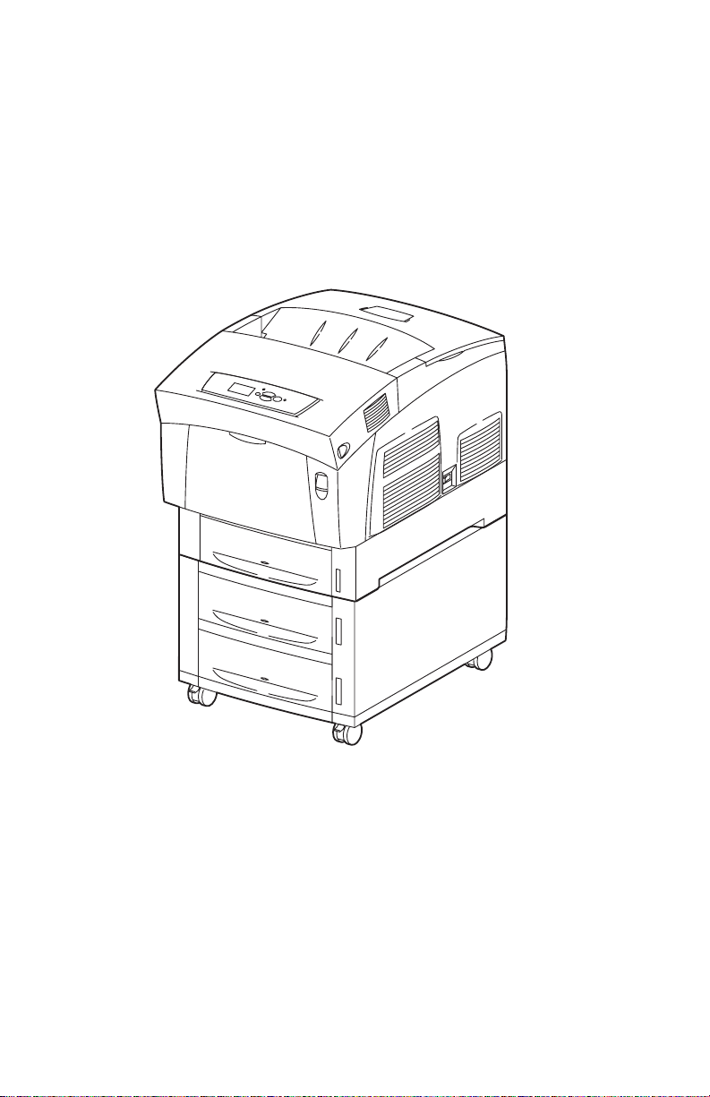
The Xerox Phaser® 6250 Color Laser Printer Service Manual is the primary
document used for repairing, maintaining, and troubleshooting the printer.
T o ensure complete understanding of this product, participation in Xerox Phaser 6250
Service Training is strongly recommended.
Phaser 6250 Color Laser Printer shown with the Optional HighCapacity Feeder
1
[
MPT
]
2
3
4
6250-01
Printer Configurations
The Phaser 6250 Printer combines a single-pass, tandem color laser design, with an
image processor supporting PostScript 3 and PCL5c page description languages. The
printer is a high performance, A4, 26 page per minute (ppm) desktop color laser
printer supporting resolutions up to 2400 x 600 dots-per-inch (dpi).
The Phaser 6250 comes in five configurations. The main differences are optional
networking, standard memory, optional high-capacity feeder, duplexing (2-sided
printing) capabilities, and optional internal hard drive.
1-2 Phaser 6250 Color Laser Printer Service Manual
Page 24

A replaceable “Configuration Chip” holds configuration information that enables or
disables built-in features as described below.
Printer Configuration
Features
6250B 6250N 6250DP 6250DT 6250DX
Max Print Speed 26 26 26 26 26
Memory (Mbytes) 128 256 256 512 512
PostScript Fonts 137 137 137 137 137
PCL Fonts 81 81 81 81 81
Embedded PCL Yes Yes Yes Yes Yes
Job Pipelining No Yes Yes Yes Yes
Secure, Proof, and Saved
Print Jobs
PDF 1.4 support No Opt* Opt* Opt* Yes
Banner-Size printing No Opt* Opt* Yes Yes
Default Resolutions (dpi) 2400x600 2400x600 2400x600 2400x600 2400x600
Photo Mode No Yes Yes Yes Yes
Job Collation No Opt* Opt* Opt* Yes
Auto-Duplex No No Yes Yes Ye s
Single Tray, 500-Sheet
Feeder
Tray 3
1000-Sheet High-Capacity
Feeder
Trays 3 & 4
Ethernet capabilities Opt Yes Yes Ye s Yes
USB, Parallel Yes Yes Yes Yes Yes
Hard Drive Opt** Opt Opt Opt Yes
* Requires optional hard drive
** Hard drive will work but does require N upgrade to support storage features
*** 500-Sheet Feeder is not stackable
No Opt* Opt* Opt* Yes
Opt Opt Opt Yes*** No
Opt Opt Opt Opt Yes
General Information 1-3
Page 25

Printer Memory and RAM Capabilities
The printer features two slots that accept 64, 128, and 256 Mbytes of SDRAM. All
combinations are allowed for 64, 128, 256, 320, 384, and 512 Mbytes. Memory
modules must have the following characteristics:
■ PC133 DRAM Standard
■ 144 Pin SODIMM
■ Serial Presence Detect
■ 3.3 Volt
The startup Page and the Configuration Page list the amount of RAM installed in the
Printer.
If the memory does not meet the above specifications, it will be ignored by the printer.
1-4 Phaser 6250 Color Laser Printer Service Manual
Page 26
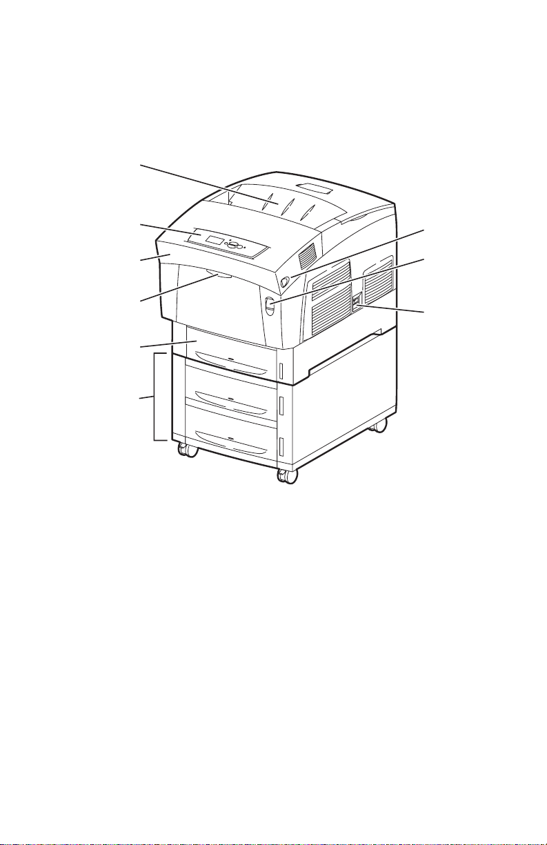
Parts of the Printer
Exterior
1
2
3
4
5
6
6250-021
1. Top Cover (Output Tray) 6. High-Capacity Feeder with Tray 3 and Tray 4
2. Control Panel (Front Panel) 7. Door Latch B
3. Front Cover 8. Door Latch A
4. Tray 1 (Multi-Purpose Tray) 9. Power On/Off Switch
7
8
9
5. Tray 2 (Universal Paper Tray)
General Information 1-5
Page 27

Phaser 6250 Front Panel Configuration
22
The Front Panel contains one tricolor LED, a display window and six function
buttons. These buttons navigate the menu system shown in the display window,
perform various functions, and select modes of operation for the printer.
LED Indicators:
■ Green = Ready to Print or
Printing
■ Flashing Yellow = Warning ■ Flashing Red = Error
■ Flashing Green = Receiving, Processing Data,
Printing or Power Saver Mode
Front Panel Button Descriptions
35
Phaser 6250
12 4678
LED (Power/Status)
1
Graphic front panel display
2
Cancel Button
3
Back Button
4
Up Arrow Button - scrolls up the menu system
5
Down Arrow Button - scrolls down the menu
6
system
OK (select) Button
7
Information Button - for additional explanation
8
or help
OK
6250-0
Front Panel Shortcuts
Mode Press this selection at Power On
Skip execution of POST diagnostics OK
Print Service Diagnostics Map INFO
Reset PostScript NVRAM BACK+OK
Password Bypass UP+DOWN
Enter Service Diagnostics BACK+INFO
1-6 Phaser 6250 Color Laser Printer Service Manual
Page 28
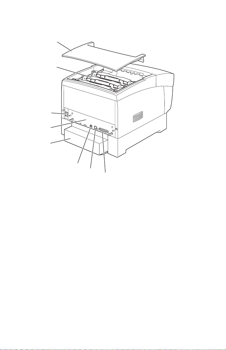
Rear View
9
4
5
1
2
3
6250-01
6
7
8
1. Top Cover 5. Paper Tray Rear Cover
2. Toner Cartidges 6. USB Connector
3. AC Power Connector 7. Ethernet 10BaseT and 100Tx
Connector
4. Image Processor Board 8. IEEE 1284 Parallel Connector
Rear Panel Configuration Interfaces
■ IEEE 1284 Parallel
■ Ethernet 10BaseT and 100Tx
■ USB
General Information 1-7
Page 29
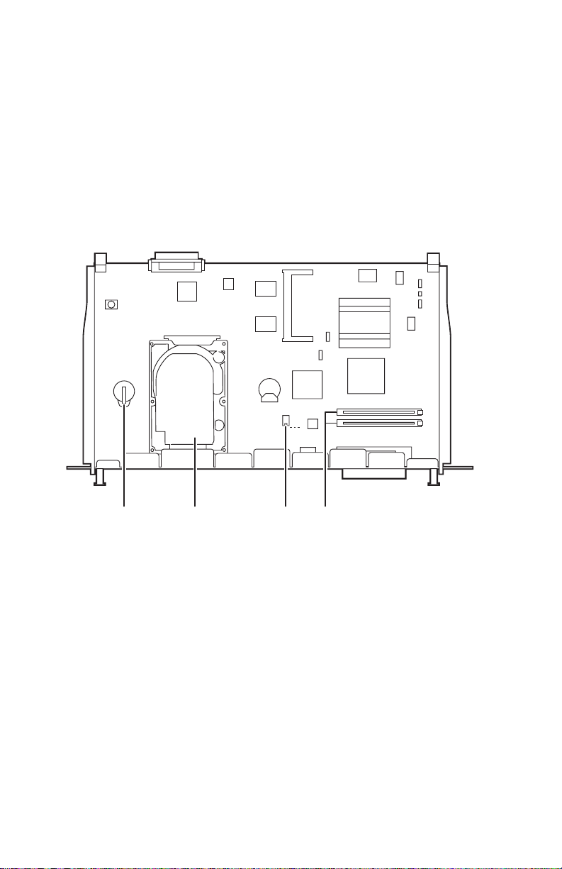
Image Processor Board
3
The components identified in the following figure need to be transferred from the old
board to the new board when installing a new Image Processor Board in the printer.
Data stored in the NVRAM can be transferred to the new board using the MCU
NVRAM Store/Restore functions instead of by moving the component. Detailed
information on the Store/Restore functions is available in "Service Diagnostic Tests"
on page 3-9.
pin 1
1234
1. Hard Drive (available option) 3. NVRAM
2. Configuration Chip 4. Memory (RAM) DIMM 1 and DIMM 2
(available option)
6250-02
1-8 Phaser 6250 Color Laser Printer Service Manual
Page 30
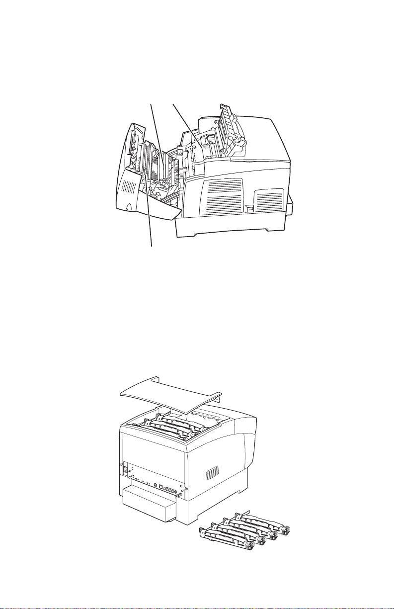
Routine Maintenance Items
20
95
A printer part or assembly that has a limited life, and requires periodic replacement.
2
1
3
1. Transfer Roller 3. Fuser Assembly
2. Imaging Unit
6250-0
Consumables
Consumables consist of the four toner cartridges used in the printer.
6250-4
General Information 1-9
Page 31

Consumable Life Counter Behavior
Internal counters track Consumables and Routine Maintenance Items life usage and
store the values in NVRAM. The image processor board monitors these counters in
order to display the near end-of-life and end-of-use messages.
Life ratings are based on A-size sheets at 5% coverage. Imaging Unit life ratings are
based on average 4 page job length.
Consumables Print Life
Toner Cartridges
High-Capacity
Standard Capacity
Routine Maintenance Items
Imaging Unit 30,000
Fuser Assembly 100,000
Transfer Roller and Waste Box 15,000
Feed Roller Kit* up to 100,000
* No life tracking for this item
8,000
4,000
1-10 Phaser 6250 Color Laser Printer Service Manual
Page 32

Printer Specifications
Physical Dimensions and Clearances
Print Engine Dimensions Value
Height: 445 mm (17.52 in.)
Width: 439 cm (17.28 in.)
Depth: 638 mm (25.12 in.)
Weight: Approximately 36.5 kg (80.5 lb.) Print engine
Optional High-Capacity
Feeder Dimensions Value
Height: 336 mm (13.23 in.) Optional Paper Tray Assembly
Width: 439 cm (17.28 in.)
Depth: 563 cm (22.17 in.)
Weight: Approximately 15 kg (33 lb.) no Paper Tray(s) installed
Optional 500-sheet
Feeder Dimensions Value
Approximately 56.5 kg (124.5 lb.) with Paper Tray(s) installed
Approximately 20 kg (44 lb.) with Paper Tray(s) installed
Height: 172 mm (6.77 in.) Optional Paper Tray Assembly
Width: 439 cm (17.28 in.)
Depth: 563 cm (22.17 in.)
Weight: Approximately 7 kg (15.4 lb.) no Paper Tray installed
Approximately 12 kg (26.4 lb.) with Paper Tray installed
Clearance Value
Top: 350 mm (13.78 in.)
Left: 100 mm (3.94 in.)
Right: 150 mm (5.91 in.)
Front: 600 mm (23.62 in.)
Rear: 200 mm (7.87 in.)
Mounting surface level
tolerance:
Within 3 degrees of horizontal with all four feet in contact with
the surface.
General Information 1-11
Page 33

Functional Specifications
Functional Specifications
Characteristic Specification
Printing process Imaging System - 4-tandem drums, electro-photographic system
Color medium Yellow, Magenta, Cyan, and Black Toner Cartridges
Resolution /
Addressability
Operating Modes Print Mode: Print Engine capable of making prints immediately.
Continuuous
Operating Printing
Speed
ppm = pages per
minute
ipm = inches per
minute
using intermediate drum transfer rolls (IDTs).
Exposure System - Semiconductor laser, simultaneous scanning
by 4 beams.
Development System - Dry type 2-component developer.
Fusing System - Heat fusing, free nip-belt system.
Draft 600 x 600 dpi
Enhanced 2400 x 600 dpi (Default)
Photo 2400 x 600 dpi*
* Not available on the Phaser 6250B.
Ready Mode: 20 seconds from completion of a print.
Sleep/ Low Power/ Power Saver Mode: Entered after a specified
period of Print Engine inactivity since completion of the last print.
Mode Paper Size / wt g/m
600/2400 dpi Letter / A4
65 -130 26/24 ppm 15 ipm
100-163 13/12 ppm 7.8 ipm
160-216 13/12 ppm N/A
600/2400 dpi Legal
65 -130 19 ppm 16 ipm
100-163 10 ppm 7.8 ipm
160-216 10 ppm N/A
2
Simplex Duplex
600/2400 dpi Envelope/Postcard
160-216 13 ppm N/A
600/2400 dpi Letter / A4 / OHP 8.6/8 ppm
Letter / A4
Photo Glossy Paper 8.6/8 ppm 5 ipm
100-200
Cleaning Cycle interval
for continuous printing
Print speed will be reduced if the print job is larger than the
cleaning cycle interval.
IU Print Volume Draft Enhanced Photo
Pages Pages Pages
0 - 5 K Pages 53 31 22
5 - 10 K Pages 35 26 18
10 - 15 K Pages 35 26 18
15 - 20 K Pages 35 26 18
20 - 25 K Pages 29 22 13
25 - 30 K Pages 29 22 13
>30 K Pages 29 22 13
1-12 Phaser 6250 Color Laser Printer Service Manual
Page 34

Functional Specifications (Continued)
Characteristic Specification
First Print-Out
(in seconds)
(Letter/A4)
(printer in Ready state)
Warm-up time 30 seconds from cold start (power off condition)
Mode Tray 1 Tray 2 Tray 3 Tray 4
Simplex, 600 dpi 14.5 15 16.5 18
Duplex, 600 dpi 23 23.5 25 26.5
Simplex, half-speed 23.5 24.5 27.5 30.5
Duplex, half-speed 38.5 39.5 42.5 45.5
Electrical Specifications
Characteristic Specification
Primary line voltages 110-127 V Printer - (90 - 140 V) 13 amp circuit
220-240 V Printer - (198 - 264 V) 7-8 amp circuit
Primary line voltage
frequency range
Power consumption at
rated voltage input
100-120 V Printer - 50/60 Hz + 3Hz
220-240 V Printer - 50/60 Hz + 3Hz
Mode Condition 100/120 VAC 220/240 VAC
Print Mode Max.. 1000 W or less 1000 W or less
Ready Mode Fuser On 180 W or less 180 W or less
Sleep Mode Fuser Off 45 W or less 45 W or less
Environmental Specifications
Characteristic Specification
Temperature:
Operating
Transportation
Storage
24 month maximum
1 month maximum
Humidity
Operating
Transportation
Storage
Altitude
Operating
Transportation
Acoustic Noise
Idle
Printing
Optimal print-quality range: 17o to 26o C (62o to 80o F)
10o C to 32o C (50o F to 90o F)
-30o C to +50o C (-22o F to 122o F)
Normal: 0o C to 35o C (32o F to 95o F)
Severe: -20o C to 40o C (-4o F to 104o F)
Optimal print-quality range: 35% to 70%
10% - 85%
30% - 85%
5% - 95%
0 - 2,500 meters (8,000 ft.)
0 - 6,092 meters (20,000 ft.)
Printer Only With Feeder Option
35.0db or less 35.0db or less
55.0db or less (Full Speed) 55.0db or less (Full Speed)
52.0db or less (Half Speed) 53.0db or less (Half Speed)
General Information 1-13
Page 35

Media and Tray Specifications
Specification Trays
Printable
Area
Supported
Media Sizes
Supported
Media Types
and Weights
Supported
Envelopes*
* Some wrinkling and embossing may occur when printing envelopes.
Minimum margins = 5 mm (0.2 in.) on all sides
Maximum paper size = 215.9 mm x 355.6 mm (8.5 in. x 14 in.)
Minimum paper size = 88.9 mm x 139.7 mm (3.5 in. x 5.5 in.)
Paper Type
Letter
Legal
Executive
Statement
US Folio
A4
A5*
A6
B5 JIS
ISO B5
Custom Size & Banner
Type Weight
Plain Paper 64- 90 g/m2 (17 - 24 lb. Bond)
Heavy Plain Paper 85 - 130 g/m2 (22 - 28 lb. Bond)
Phaser 25-Series Premium
Transparency Film (Only)
Thin Card Stock 100 - 163 g/m2 (26 - 60 lb. Cover)
Thick Card Stock 160 - 216 g/m2 (59 - 80 lb. Cover)
Labels N/A
Letterhead 85 - 130 g/m2 (22 - 28 lb. Bond)
Glossy Coated Paper** 120 - 163 g/m2 (81 - 110 lb.)
Business & Greeting Cards N/A
CD/DVD Labels and InsertsN/A
Digital Photo Paper 163 g/m2 (60 lb. Cover)
Phaser Premium Post- 176 g/m2 (65 lb. Cover)
cards
Phaser Glossy Trifold 176 g/m2 (65 lb. Cover)
Brochures
Phaser Weatherproof 100 g/m2 (27 lb. Bond)
Paper
Envelopes Weight 20 - 24 lb. Bond
Commercial #10 4.12 x 9.5 in
Monarch Envelope 3.87 x 7.5 in
A7 Envelope 5.25 x 7.25 in
Custom
DL Envelope 110 x 220 mm
C5 Envelope 162 x 229 mm
C6 Envelope 114 x 162 mm
B5 Envelope 176 x 250 mm
Envelopes with hot melt type glue are not supported in this
printer. Do not use envelopes with windows or metal clasps.
Size
8.5 x 11 in.
8.5 x 14 in.
7.25 x 10.5 in.
5.5 x 8.5 in.
8.5 x 13 in.
210 x 297 mm
148 x 210 mm
105 x 148 mm
182 x 257 mm
176 x 250 mm
8.5 x 22.86 in.
All Trays
All Trays
All Trays
All Trays
Tray 1 Only
All Trays
All Trays
Tray 1 Only
Tray 1 Only
All Trays
Tray 1 Only
Tray 1 Only
All Trays
All Trays
Tray 1 & 2
Tray 1 Only
Tray 1 Only
Tray 1 & 2
All Trays
All Trays
Tray 1 Only
Tray 1 Only
Tray 1 Only
Tray 1 Only
Tray 1 Only
Tray 1 & 2
Tray 1 Only
1-14 Phaser 6250 Color Laser Printer Service Manual
Page 36

Note
Specification Trays
Speciality
Media
Tray Capacity Universal Tray Tray 1/MPT
Phaser 25-Series Premium Transparencies
Letter 216 x 279 mm 8.5 x 11 in.
A4 210 x 297 mm 8.27 x 11.69 in.
Other sizes will be handled through Tray 1 with use of the
custom size option.
Phaser Premium Postcards
Letter 216 x 279 mm 8.5 x 11 in.
A4 210 x 297 mm 8.27 x 11.69 in.
Phaser Glossy Trifold Brochures
Letter 216 x 279 mm 8.5 x 11 in.
A4 210 x 297 mm 8.27 x 11.69 in.
Weather Proof Paper
Letter 216 x 279 mm 8.5 x 11 in.
A4 210 x 297 mm 8.27 x 11.69 in.
Standard Paper 500 Sheets 100 Sheets
Transparency 100 Sheets*** 50 Sheets
Envelopes N/A 10 each
* A5 paper is supported from all trays in Japanese models only
** Glossy paper can be used in all trays on the 6250
*** Tray 2 only
Trays 1& 2
Only
Tray 1 Only
Tray 1 Only
Tray 1 Only
Tray 1 Only
Trays 1& 2
Only
For duplex configured printers, auto duplex operation is available through Tray 1
(MPT) and Trays 2, 3, and 4. Refer to the Paper Tips page for information on
which paper types can be used for duplex printing.
General Information 1-15
Page 37

Theory of
Operation
In this chapter...
■ Overview
■ Printer Controls
■ Paper Path of the Printer
■ Major Assemblies and Functions
Chapter
2
Page 38

Overview of the Phaser 6250 Color Laser
Printer Theory of Operation
Summary of the Printing Process
The Phaser 6250 Color Laser Printer is a ‘full-color laser printer’, that utilizes
electrophotographic recording principals to place a full color image onto the print
media. The system, contains a drum and developing unit for each color (yellow,
magenta, cyan and black (YMCK)), and places the toner image of each color onto
print media producing full-color prints through three transfer units (primary transfer
units IDT1 (2 ea) and secondary transfer unit IDT2 (1 ea)).
A summary description of the printing process is presented in the following Steps, see
the illustration on the following page as a reference:
1. Charging: The charge roller (RTC) is negatively charged by the high voltage
power supply (HVPS) and is kept in contact with the drum surface to provide a
uniform negative charge on the drum as it rotates at a constant speed. This occurs
simultaneously for YMCK. The refresher is a conductive brush that is also
negatively charged by the HVPS to pick off any toner particles left on the drum
after image transfer to the IDT.
2. Exposure: The laser unit emits laser beams in response to image data from the
Image Processor board. The laser beams are directed onto the drum surface
through a system of mirrors and lenses. A rotating polygonal mirror causes the
laser beams to scan the drum surface from end to end (axially) as it rotates. The
beams are turned on to print a pixel and off when no printing is required. The
negative char ge on the drum surf ace is reduced at each point where the ener gized
laser beam strikes, to form an invisible electrostatic latent image on the drum
surface. This process is performed simultaneously for YMCK.
3. Development: Toner is electrostatically attached to the invisible latent image
on the drum surface to form the visible image on the drum. Toner is fed into the
developer using the agitator and auger. The toner and the carrier in the developer
form a homogeneous layer on the magnet roller in the developer. The magnet
roller turns against the surface of the drum and is kept at a constant negative
potential. At areas on the drum surface where the negative charge has not been
reduced by the impact of laser light, potential between the drum and the toner
particles is lower than that between the magnet roller and the toner particles. At
areas where the drum charge has been reduced, the potential between the
particles and drum is higher than between the magnet roller and toner particles
are attracted to the drum. A thin semiconductive sleeve on the magnet roller is
vibrated by an AC voltage to encourage migration of the toner particles to the
drum. When the toner particles attach to the drum, the negative charge of the
particles reduces drum potential at that point, thus reducing the attraction of
additional toner particles. This process is performed simultaneously for YMCK.
4. Primary Transfer (drum --> I DT1): The toner image formed on the individual
drum surface is transferred onto the surface of the IDT1 (intermediate Drum
Transfer 1: intermediate transfer roller 1). There are two IDT1’s: one for yellow
and magenta and one for cyan and black. IDT1 is conductive and receives a high
positive charge from the HVPS. The ne gatively charged toner image on the drum
2-2 Phaser 6250 Color Laser Printer Service Manual
Page 39

surface is attracted by the high positive potential and transfers to IDT1. During
this transfer, the remaining negative charge on the drum is neutralized by the high
positive charge on IDT1.
5. Secondary Transfer (IDT1 --> IDT2): The toner images formed on both
IDT1 surfaces are then transferred onto the surface of IDT 2 to create a complete,
4-color toner image. IDT2 is also conductive and receives a positive voltage from
the HVPS. The received voltage puts IDT2 at a higher potential than IDT1 thus
attracting the toner image and facilitating the transfer.
6. Cleaning: The IDT1 cleaner consists of a conductive roller brush rotating in
contact with IDT1 after the point where the toner is transferred to IDT2. The
cleaner receives a high positive voltage from the HVPS allowing it to electrically
attract any toner particles remaining on IDT1. Toner remaining on both IDT1’s
after the image transfer to IDT2 is temporarily stored in the IDT1 cleaners.
7. Tertiary Transfer: The finished toner image on IDT2 is transferred onto the
print media using the voltage supplied by the transfer roller. The conductive
transfer roller receives a high positive voltage from the HVPS that puts it at a
higher potential than IDT2. Since the transfer roller is located behind the print
media, the 4-color toner image is attracted to the high potential and deposits on
the surface of the print media.
8. Cleaning: The IDT2 cleaner consists of a conductive roller brush rotating in
contact with IDT2 after the point where the toner is transferred to the print media.
The cleaner receives a high positive voltage from the HVPS allowing it to
electrically attract any toner particles remaining on IDT2. Toner remaining on
IDT 2 after the image transfer to the print media is temporarily stored in the IDT2
cleaner.
9. Static Elimination: The positive charge on the print media can cause image
quality problems by scattering toner. To prevent this, negative DC voltage from
the HVPS is applied to the back side of the print media by the Detack Saw,
located on the Transfer Roller Assembly. This negative charge neutralizes and
eliminates the charge on the print media resulting from the tertiary transfer.
10. Fixing: The finished toner image is unstable and easily smeared. To fix the
image, the print media goes through the Fuser Assembly where it passes between
a pressure belt and the heat roller. The toner is fused onto the print media by the
combination of heat and pressure.
11. Cleaning: During the general cleaning process, the voltage applied to the IDT
rollers and drums go through a cycle of changes to move the negative and
positive charged toner particles from the cleaners and IDTs and then the transfer
roller. The toner stored in the IDT1 cleaner, the IDT 2 cleaner and on the transfer
roller is removed and deposited into the transfer roller waste recovery bin. Toner
from the charge roller and refresher is also removed and deposited into the
transfer roller waste recovery bin. In each case the voltage at the point of
attraction is set high and the voltage at the point of disposal is set to 0V with the
result that the toner is moved to the high potential until at last it is deposited on
the transfer roller. Toner is removed from the transfer roller by the attached
cleaning blade and deposited in the attached recovery bin.
Theory of Operation 2-3
Page 40

Drum Y
4
6
[
r]
P
Drum M Drum C Drum K
Charged
with
(1)
electricity
Exposure
(2)
Develop-
(3)
ment
Primary transfer
(4)
(Drum → IDT1)
Intermediate
transfer unit
( IDT1)
(5)
Intermediate
transfer unit
( IDT2)
Paper
rinting Process Flowchart
[(1) Changing with electricity]
(1) Changing with electricity]
Developer(Y)
[(3) Development]
Drum(M)
Developer(M)
[(3) Development]
[(1) Changing with electricity]
Developer(C)
[(3) Development]
Drum(C)
[(1) Changing with electricity]
Developer(K)
[(3) Development]
Printing Process Components
Charged
with
(1)
electricity
(2)
Exposure
Develop-
(3)
ment
Cleaning
(6)
( IDT1)
Secondary transfer
( IDT1
→
IDT2)
(8)
Cleaning ( IDT2)
(7)
Tertiary transfer
( IDT2
→
(9)
Static elimination
(10)
Fixing
RTC
RTC
RTC
RTC
Drum(K)
Paper)
Refresher
Refresher
(1)
(2)
(3)
Intermediate
transfer unit
( IDT1)
(11)
Refresher
Charged
with
electricity
Exposure
Development
Primary transfer
(4)
(Drum → IDT1)
Cleaning
(general)
Transfer
Roller
Drum(Y)
Refresher
IDT1
[(4) Primary transfer]
[(5) Secondary transfer]
IDT1
[(4) Primary transfer]
[(5) Secondary transfer]
IDT1 Cleaner
[(6) Cleaning
(11) Cleaning]
Charged
with
(1)
electricity
(2)
Exposure
Develop-
(3)
ment
Cleaning
(6)
( IDT1)
6250-02
IDT1 Cleaner
[(6) Cleaning
(11) Cleaning]
IDT2 Cleaner
[(8) Cleaning
(11) Cleaning]
IDT2
[(5) Secondary transfe
[(7) Tertiary transfer]
6250-02
2-4 Phaser 6250 Color Laser Printer Service Manual
Page 41

Print Modes
There are three print modes: Draft mode, Enhanced mode, and Photo mode. These are
based on the resolution (600 dpi or 2400 dpi) and, depending on the media type, can
also be affected by process speed (full speed/half speed/one-third speed).
■ Draft mode: 600 X 600 dpi resolution. Used to check layout. Provides
reduced toner usage.
■ Enhanced mode: 2400 X 600 dpi resolution. General purpose mode for crisp
bright color prints. Recommended for most office use. It is the default mode
■ Photo mode: 2400 X 600 dpi resolution. Highest quality color print with
very smooth color shades. When using photo paper or OHP, gloss is raised
by setting the process speed to one-third.
Printer Controls
Paper Size Control
The paper size selection is controlled by three paper size switches located in each
paper tray slot. The switch condition is set by moving the paper guide in the tray. This
in turn sets the plastic “fingers” on the side of the paper tray to a specific postion that
activates the correct switch combination for the selected paper size.
Paper Size Switches are indicated as SW1, SW2, and SW3
Paper Size Switch
Paper Size
SW1 SW2 SW3
LEGAL14" ON ON ON
US FOLIO (LEGAL 13)" ON ON OFF
EXECUTIVE ON OFF ON
B5 ON OFF OFF
A4 OFF ON ON
A5 (for reference only, supported in Tray 1 [MPT]
only)
LETTER OFF OFF ON
No Tray OFF OFF OFF
OFF ON OFF
Theory of Operation 2-5
Page 42

Selective Control; Paper Pick
Unless changed in printer setup, the default tray is Tray 2. Trays in the optional HighCapacity Feeder are identified as Tray 3 and T ray 4. The tray in the optional 500-sheet
Feeder is identified as Tray 3.
Laser Light Intensity Control
The Laser Unit in the Phaser 6250 printer has four laser diodes: one each for yellow,
magenta, cyan, and black. The diodes control circuits adjust the light intensity for
each color automatically. Image data is transmitted to the laser diodes in the Laser
Unit as digital signals. The laser diodes convert the image data from digital signals to
optical signals. The laser assembly monitors and adjusts the light intensity of the laser
beams to attain a stable electrostatic image. Variations in drum sensitivity may
prevent the system from obtaining a proper electrostatic image.
Process Control
For stable printing, the parameters related to forming both the electrostatic and toner
image must be continuously monitored and adjusted by the printer. Parameter
correction and control over the entire printing process is called “process control”.
There are two main areas of control:
■ Bias Control
■ Toner Density Control
To supplement these two controls, the following are provided:
■ High-Area Coverage Mode Control
■ Admix Mode Control
■ Toner Density Control (CTD) Sensor (ADC - Automatic Density Control)
LED light density setting.
Bias Control
To attain stable image density , toner dens ity is monitored for each color and the drum
charging voltage and biasing DC voltages are adjusted according to the monitored
results for each color.
The bias control adjustment is made immediately before the start of printing, if any of
the following conditions is satisfied:
■ First print produced after the power on.
■ Cumulative print count exceeds 16 since powe r on.
■ A cleaning cycle is executed during continuous printing.
2-6 Phaser 6250 Color Laser Printer Service Manual
Page 43

Bias control operates as follows:
A
m
1. The Temperature/Humidity Sensor sets the target values of the drum charging
voltage and biasing DC voltage.
2. Bias control test patches (see the adjacent figure for
patch configuration) of each of the four toner colors
bout 11mm
(yellow, magenta, cyan, and black) are generated and
About 12mm
transferred to the Transfer Roller.
3. The CTD (ADC) Sensor compares an area on the
Transfer Roller where no toner is present with the test
patches to determine toner density for each of the four
Y
About 3mm
M
About 57m
colors.
4. The density measured in Step 3 is compared with the
C
target value set in Step 1 and the resulting difference
is used to adjust the drum charging voltage and the
biasing DC voltage for each toner color.
K
6250-069
Toner Density Control
Toner density must be kept constant to attain a stable print image. To achieve this
goal, the rate at which toner is dispensed must be adjusted to exactly match the rate at
which it is consumed. There are two systems that work in conjunction to control toner
density: the Pixel Count Dispense Control (PCDC) and the Toner Density Control
(CTD). (The CTD uses data from the ADC sensor, measured as described in the
preceding paragraphs covering bias control.)
PCDC: The amount of toner consumed in the developing process is calculated by
counting the digital pulses applied to the Laser Unit. The toner motor is then driven
for a period determined by the calculated result to supply toner to the developer,
equivalent to the amount dispensed.
CTD (ADC): The toner test patches of each color (yellow, magenta, cyan, and black),
are generated and transferred to the transfer roller as specified in the Bias Control
section. The CTD (ADC) sensor measuers the density of each patch. The printer
adjusts the toner dispense time, which changes the quantity of toner to be dispensed.
This calculation is made separately for each color. The CTD adjustment is made
following completion of printing if either of the following conditions is satisfied:
■ Cumulative print count since power on exceeds 16 pages.
■ When a cleaning cycle is executed during continuous printing.
If either of the preceding control calculations results in an adjustment to the toner
quantity to be dispensed, the result is calculated in terms of number of revolutions of
the Toner Motor. For this description, this value is called the dispense count.
The dispense count calculated as specified above, is implemented over the next 8
prints. If 16 dispense counts are required as a result of low toner density during the
CTD calculation, 2 dispense counts are added during each of the next 8 prints. This is
in addition to any counts added or subtracted during each print as a result of PCDC.
Theory of Operation 2-7
Page 44

If toner density is too great (excess toner) and 16 dispense counts are required to
67
T
C
D
C
T
subtract this amount, the adjustment is accomplished by subtracting 2 counts from the
calculated PCDC count over each of the subsequent 8 prints. If the excess amount
cannot be subtracted in 8 print cycles, it is subtracted in the ninth and subsequent
prints.
otal dispense counts
orrection amount by ADC +16
ispense counts by PCDC
orrection amount by ADC -8
otal dispense counts
4534223432
Even allotment in first 8 prints
2 3 1 2 0 0 1 2 3 2
1201000022
6250-0
High-Area Coverage Mode
Continuous printing of an image with density exceeding the toner dispense capability
causes the toner density in the developer to be lowered below the target toner density.
The high area coverage mode delays feeding of the next page, and dispenses toner
during this time so that the toner density time reaches the specified value during
continuous printing.
Admix Mode
If the high area coverage mode can not deal with the reduction of toner density in the
developer or if the machine is moved to an environment wit h a di fferent humidity
level, the reference value for the toner density will change. This causes a large
discrepancy between the measured values from the CTD sensor and the referenced
value for the toner density.
Admix mode dispenses the toner immediately to prevent low-toner density. If the
patch density result measured by the CTD Sensor is lower than the reference value
from the toner density control, then the admix mode is initiated.
LED Light Density CTD (ADC) Control of Sensor
The CTD (ADC) sensor is a reflective sensor that emits light from an LED in the
sensor and detects the reflected light from the transfer roller. For exact density
measurement, the sensor output value (reflected light density) must be the specified
value when no toner is put on the Transfer Roller. The reflected light density varies
2-8 Phaser 6250 Color Laser Printer Service Manual
Page 45

depending on the Transfer Roller surface condition or dirty condition of CTD (ADC)
sensor surface. The light density emitted from the LED is controlled so that the
reflected light density meets the specified value.
This control is implemented in two ways:
■ Sets the light density so that the light reflected satisfies a specific value.
■ Adjusts the subsequent light density to be within a specific tolerance value.
1. Light Density Setting
The reflected light density can vary greatly if the transfer roller has been replaced or
the CTD (ADC) sensor has been cleaned. To deal with this variance the light density
is reset when the power is turned on or the front cover is opened and closed.
The intensity of the LED increases gradually and the set value is adjusted when the
output of the CTD (ADC) sensor does not meet the specified value. If the output of
the CTD (ADC) sensor does not reach the specified value, even though the light
density is increased to the maximum limit, the controller signals the sensor is dirty. If
the sensor output is extremely high, the controller will signal that the sensor is faulty.
2. Light Density Adjustment
At the execution of automatic density control, the light density adjustment is made
just before the patches for toner density control are generated.
Light is emitted from the LED using the current light density setting, to check if the
output value of the CTD (ADC) sensor is within the specified range. If the output
value is low, light density is increased. If the output value is high, the light density is
decreased.
If the output value is less than the first lower limit, the controller signals the sensor as
dirty and generates a warning. If the output value is less than the second lower limit,
the controler signals that the sensor is faulty and stops the printing.
Color Registration Control
The printer uses a quad system where drums and developers are used exclusively for
each of the four colors (yellow, magenta, cyan, and black). Images are formed on the
drums, in the respective colors, and then layered to form one image. To avoid a
positional shift between the different color images, the color registration control
calculates how much the registration has shifted by comparing each of the other color
patches in the registration string to the black bar that precedes it. Shift is corrected by
adjusting the laser write timing to compensate.
Color registration control is made depending on the internal temperature and print
count at the execution of process control.
Theory of Operation 2-9
Page 46

+n of this control is outlined below:
1. With no toner on the Transfer Roller, the output value of Sensor, CTD (ADC) is
measured to determine the threshold value.
2. Patches for color registration control are
generated on the Transfer Roller. These
10mm
patches are composed of 10mm lines of
each toner color in the following order: K,
C, K, M, K, and Y with each color
dispensed in the amount of four dispense
counts. The string of patches is led by a
black trigger patch that is larger than the
registration patches.
3. The density of patches generated by the
About one turn of BTR
CTD (ADC) sensor is measured.
4. The amount of registration shift is
calculated from the threshold value
determined in Step 1 and the patch density
measured in Step 3.
6250-068
5. The laser write timing is changed to
compensate for the amount of registration
shift.
K
K
C
K
M
K
Y
2-10 Phaser 6250 Color Laser Printer Service Manual
Page 47

Transfer Roller Assembly Control
Detecting the Installation of the Transfer Roller Assembly
Although there is no seperate sensor for this, the output of the CTD Sensor is used to
detect installation or absence of the Transfer Roller when power to the printer is
turned on, or the front cover is opened and closed.
Light emits from the LED of the CTD sensor with the specified intensity and if the
output of the CTD Sensor is greater than th e specified value the controller signals that
the Transfer Roller is present (installed).
If printing is stopped by a jam, the toner image will be placed on the Transfer Roller.
In this case the sensor output result is low, causing the controller to report the Transfer
Roller as missing. To prevent this, the Transfer Roller is rotated a half turn if output is
lower than the specified value. If the output of the CTD sensor is than greater than the
specified value, the controller reports installation of the Transfer Roller. If the output
remains less than the specified value, the controller reports that the Transfer Roller is
not installed.
Detecting the Life of the Transfer Roller Assembly
The Transfer Roller Assembly consists of a bias transfer roller and a waste toner
recovery space. End of life of the Transfer Roller is detected when the waste toner
recovery space becomes full.
The full waste toner recovery space is detected by the Toner Full Sensor.
1. Status of the waste toner recovery space is checked:
■ When the power is turned on.
■ When the front cover is opened and closed.
■ When paper exits the print engine.
2. “Transfer Roller is at End of Life” error message is generated when the toner full
sensor detects the waste toner recovery space is full.
3. “Replace Transfer Roller ” warning message is generated if the print count and
the toner dispense time are counted and the total count exceeds 15,000 prints.
4. “Transfer Roller is at End of Life” error/ “Replace Transfer Roller ” warning
messages are reset if the toner full sensor does not detect a full waste toner
recovery space when power is turned on, or the front cover is opened and closed.
Theory of Operation 2-11
Page 48

Toner Control
T oner Cartridge installation is detected by the Toner Present (CTG-In) Switch, and the
presence of toner is detected by the Tone r Low Sensor. These switches and sensors are
provided for each toner color (CMYK), and detection is made for each individually.
Toner Low Sensor
The toner low sensor checks one color every 3.5 seconds, requiring 14 seconds to
detect all four colors.
The toner low sensor is attached to the Toner Cartridge Holder Assembly. It detects
toner dispensed by the toner motor from the toner cartridge into the auger tube.
The toner low sensor can make a false detection if toner has stuck to the surface of the
sensor. To prevent this, a film attached near the auger in the toner cartridge holder
assembly cleans the sensor surface whenever toner is dispensed. This film rotates with
the auger as toner is dispensed, scraping toner off the toner lo w sensor surface.
The toner low sensor may detect toner even if toner is not present or may not detect
the toner even if toner is present, depending on the film position when the toner motor
stops. This is avoided by the printer’s internal toner presence control.
Toner Presence Control
1. Checks for toner presence when the power is turned on, or after the front co v er is
opened and closed. Checks every 14 seconds when printing.
2. The "Toner Empty” warning is displayed when the counter on the Customer
Replaceable Unit Monitor (CRUM) indicates that the toner is empty.
3. The "Toner Empty” error is displayed when the toner low sensor detects that
toner is empty.
4. When a new toner cartridge is installed (“Toner Empty error” not being
generated), toner is dispensed for 1.7 seconds. At the next toner control timing, if
the toner low sensor detects toner present, the “Toner Full”, "Toner Empty
Warning", and "Ton er Emp ty Error" are reset. When toner is dispensed and the
toner low sensor detects toner present three or more times consecutively, the
controller regards this status as "Toner Present".
5. If the toner low sensor does not detect toner present, toner will be dispensed for
1.7 seconds again 5 seconds later. If toner present is not detected after executing
toner dispense three times and if toner cartridge dispense time shows 0, “Remove
Ribbon From ‘x’ Cartridge” error is displayed.
2-12 Phaser 6250 Color Laser Printer Service Manual
Page 49

Fuser Control
Fuser Temperature Control
During fuser temperature control the printer’s target temperature is set. The heat roller
surface temperature is controlled to match the target temperature by turning the heater
lamp on/off.
The heat roller surface temperature is detected by two sensors. A non-contact sensor
in the middle of the roller is checked for 60ms and the Temperature Sensor at the edge
of the roller is checked for 20ms to maintain an even temperature across the roller. If
the results of the 80ms cycle show the temperature is higher than the target, the heater
lamp is turned off. If the detection result is low, the heater lamp is turned on.
For the target temperature, different temperatures are set for standby, printing, and
process control. The target temperature is also changed according to the inside
temperature detected with the temperature/humidity sensor, print count, print mode,
input power supply voltage and paper type.
Cool Down
During printing, the temperature distribution of the heat roller becomes uneven
between paper and non-paper. To make the heat roller temperature as even as
possible, a wait time is provided and the heater lamp is kept off. This is called the cool
down.
A cool down is executed according to the number of sheets continuously printed when
a set, printing with a certain type and size of print media is completed, and when the
print media type or size is changed. The cool down, which results in a pause, occurs
evenly in the middle of several hundred sheets of continuous printing.
Theory of Operation 2-13
Page 50

Paper Path of the Printer
R
P
54
: Laser beam
: Paper path
: Paper sensors
EXIT ROLL
APER PICK ROLLER (T2)
PAPER PICK ROLLER (T3)
PAPER PICK ROLLER (T4)
PAPER FEED ROLLER (T2)
PAPER FEED ROLLER (T2)
PAPER FEED ROLLER (T4)
MID ROLL
TURN ROLL
TURN CHUTE ASSY (T2)
TURN ROLL ASSY (T2)
TURN CHUTE ASSY (T3)
TURN ROLL ASSY (T3)
PAPER FEED TRAY
PAPER FEED ROLLER (T3)
TURN CHUTE ASSY (T4)
TURN ROLL ASSY (T4)
PAPER FEED TRAY
FUSER ASSY
DUPLEX ROLLE
TRANSFER ROLLER
METAL ROLL
REGISTRATION ROLL
FEED ROLL ASSY
RETARD ROLLER
6250-0
2-14 Phaser 6250 Color Laser Printer Service Manual
Page 51

Paper Path Route
3
OPTIONAL FEEDERS
Paper Tray 4
Paper Tray 3 Paper Tray 2
Tray 1 (MPT)
Paper feed by
"Paper Pick Assy (T4)"
Paper feed by
"Paper Feed Rollers"
(Nudge and Retard)
(Tray 4)
Paper transfer by
"Tray 4 Turn Roll"
and
"Tray 4 Turn Chute Assy"
Paper transfer by "Tray 3 Turn Roll"
and "Tray 3 Turn Chute Assy"
Paper transfer by the
Paper transfer by the "Chute Assembly, Registration (REGI) (Metal and Registration Rolls)
Paper feed by
"Paper Pick Assy (T3)"
Paper feed by
"Paper Feed Rollers"
(Nudge and Retard)
(Tray 3)
"Tray 2 Turn Roll"and "Tray 2 Turn Chute Assy"
Paper feed by
"
Paper Pick Assy
Paper feed by
"Paper Feed Rollers"
(Nudge and Retard)
(Tray 2)
(T2)"
"Paper Feed (Retard) Roller"
"Tray1 Feed Roller"
Paper transfer by the "Imaging Unit IDT2" and "Transfer Roller"
Paper transfer by the "Fuser Assembly" (Heat Roll and Fuser Belt)
Paper transfer by the "Fuser Assembly "Exit Roll" and "Pinch Roll"
Paper feed by
and
Paper transfer by
"Turn Roll"
and
"Pinch Roll"
Paper transfer by the "Chute Assembly, Exit" and "Chute Assembly, Out"
Print output
Paper transfer to duplex path by
reversing "Exit Roll" and "Mid Roll"
Paper transfer by "Duplex Rollers"
to Print Output
6250-49
Theory of Operation 2-15
Page 52

Major Assemblies and Functions
64
The following section details all major components of the printer and their relative
functions.
Frame and Drive Assemblies
1
2
6250-0
1. Developer Drive Assembly: Supplies the drive to the Imaging Unit
Developer.
2. Main Drive Assembly: Supplies the drive to the following parts:
■ Paper Feeder
■ Retard Housing Assembly
■ Chute Assembly, Out (MPT position)
■ Chute Assembly, Registration
■ Imaging Unit (IDT 1, IDT 2, Drum)
■ Transfer Roller
2-16 Phaser 6250 Color Laser Printer Service Manual
Page 53

Main Drive Assembly - Transmission Route
7
MAIN DRIVE ASSY
GEAR IDLER IN
CLUTCH ASSY TURN
ROLL ASSY TURN GEAR IDLLER FEED
PAPER FEEDER
CLUTCH TURN
ROLL TURN
GEAR IDLLER
GEAR FEED H1
GEAR FEED1
ROLL ASSY FEED
GEAR MSI
ROLL ASSY FEED
Regi.Clutch
Regi.Roll
CHUTE REGI
IDT2
IDT1 (2)
HOUSING ASSY RETARD
CHUTE ASSY OUT
Drum (4)
IMAGING UNIT
TRANSFER
ROLLER
6250-04
Theory of Operation 2-17
Page 54

Gear Layout - Print Engine and Tray 1
2
The drawing below shows the location of the various components specified in the
Transmission Route Block Diagram on the preceding page.
5
4
2
1
FRONT
6
7
3
8
9
10
16
15
11
14
12
13
1. Retard Housing 9. Turn Clutch Assembly
2. Tray 1 Gear 10. Gear Idler Feed
3. Registration Chute Assembly 11. Gear Feed 1
4. Registration Clutch 12. Gear Feed H1
5. Transfer Roller 13. Paper Pick Assembly (Tray)
6. Chute Assembly Out 14. Gear Idler
7. Imaging Unit 15. Gear Idler In
8. Main Drive Assembly 16. Turn Clutch
6250-05
2-18 Phaser 6250 Color Laser Printer Service Manual
Page 55

Paper Tray 2
5
1
3
2
2
6250-05
1. Paper (Retard) Feed Roller: The paper retard feed roller prevents more than
1 sheet at a time from printing. The paper feed retard roller and the paper feed
nudge roller are interchangeable parts in all trays.
2. Side Guides Right and Left: The side guides move against media to align or
register the width of print media in the paper feed direction.
3. Rear Guide: The rear guide moves to determine the length of print media in the
paper feed direction. The paper size switch uses this rear guide to detect the paper
size.
Theory of Operation 2-19
Page 56

Paper Feed - Tray 2
6
3
2
4
5
8
6
7
6250-05
12
1
8
9
11
10
1. Temperature/Humidity Sensor: Detects temperature and humidity inside the
printer to adjust the charge voltage (the voltage supplied to the transfer roller and
the developing bias).
2. No Paper Sensor: Detects presence or absence of print media in the tray based
on the position of the Actuator.
3. Paper Pick Rollers: When the feed solenoid energizes, the spring feed force
engages the gear feed and the gear idler feed to turn and feed the paper from the
paper tray. This activates the pick-up assembly. After completion of one turn,
determined by a cutout in the gear feed, the gear feed and the gear idler feed are
disengaged stopping the paper retard feed roller. This allows one sheet to be fed
at a time.
4. Turn Clutch Assembly: Transfers the drive energy from the main drive
assembly to the roll turn assembly.
5. Paper Size Switch: Detects print media size and installation of the paper tray.
6. Gear Feed: See Paper Pick Rollers.
7. Spring Feed: See Paper Pick Rollers.
2-20 Phaser 6250 Color Laser Printer Service Manual
Page 57

8. Gear Idler Feed: See Paper Pick Rollers.
Note
46
1
1
9. Feed Solenoid: Controls the operation (rotation/stop) of the Feed Roller
Assembly by controlling the rotations of the Gear Feed.
10. Low Paper Sensor: The actuator lowers as print media is used in the tray.
When the actuator lowers to a pre-determined postion, it blocks the sensor beam
to trigger a low paper status. The actuator position can be seen from the front of
the paper tray allowing confirmation of the print media quantity.
11. Paper Feed Roll: See paper Pick Rollers.
12. Roll Turn Assembly: The roll turn assembly receives drive energy from the
main drive through the turn clutch and transports the print media out of the paper
tray to the registration roller.
High-Capacity Feeder Trays 3 and 4
The callouts in the following figure refer to the identifying numbers in the
preceding paragraphs. The T3 and T4 in the callouts identify the tray.
Tray 2 paper pick assembly has a different part number than the HCF Tray 3 and
Tray 4 paper pick assembly.
2(T3)
11(T3)
3(T3)
2(T3)
4(T3)
9(T3)
5(T3)
9(T4)
4(T4)
2(T4)
11(T4)
3(T4)
2(T4)
5(T4)
6250-4
Theory of Operation 2-21
Page 58

500-Sheet Feeder Tray 3
Note
05
Tray 2 paper pick assembly has a different part number than the 500-Sheet
Feeder, Tray 3 paper pick assembly.
12T3
3T3
2T3
4T3
5T3
11T3
9T3
6250-4
2-22 Phaser 6250 Color Laser Printer Service Manual
Page 59

47
1
3(T3)
3(T4)
2
6250-4
1. HCF Feeder Circuit Board: Controls the paper pick-up operation of each tray
based on communication with the Engine Control Board and information from
the sensors and switches.
Major Functions:
■ Communicates with the Engine Control Board.
■ Receives information transmitted from the sensors and switches.
■ Controls the Feeder Drive Assembly.
■ Controls the paper pick process.
■ Distributes the DC voltage power supplied from the print engine to each
component.
2. Feeder Drive Assembly: Supplies the drive to the Tray 3 and 4.
3. Low Paper Sensor: The actuator lowers as print media is used in the tray.
When the actuator lowers to a pre-determined postion, it blocks the sensor beam
to trigger a low paper status. The actuator position can be seen from the front of
the HCF allowing confirmation of the print media quantity.
Theory of Operation 2-23
Page 60

1
6
3
2
6250-40
1. 500-Sheet Feeder Circuit Board: Controls the paper pick-up operation of
tray 3 based on communication with the Engine Control Board and information
from the sensors and switches.
Major Functions:
■ Communicates with the Engine Control Board.
■ Receives information transmitted from the sensors and switches.
■ Controls the Feeder Drive Assembly.
■ Controls the paper pick process.
■ Distributes the DC voltage power supplied from the print engine to each
component.
2. Feeder Drive Assembly: Supplies the drive to the tray 3.
3. Low Paper Sensor: The actuator lowers as print media is used in the tray.
When the actuator lowers to a pre-determined postion, it blocks the sensor beam
to trigger a low paper status. The actuator position can be seen from the front of
the 500-Sheet Feeder allowing confirmation of the print media quantity.
2-24 Phaser 6250 Color Laser Printer Service Manual
Page 61

HCF Drive and Gears - Transmission Route
C
6250-444
6250-443
CLUTCH ASSY TURN
GEAR IDLER IN
GEAR IDLER
DRIVE ASSY FEEDER
GEAR IDLER
LUTCH ASSY TURN
GEAR IDLER IN
GEAR IDLER
FRONT
GEAR IDLLER IN
CLUTCH ASSY TURN
ROLL ASSY TURN
GEAR IDLER FEED
GEAR FEED1
GEAR FEED H1
PICK UP ASSY T3
GEAR IDLER FEED
GEAR FEED1
GEAR FEED H1
PICK UP ASSY T4
LOWER FEEDER DRIVE ASSY
GEAR IDLER GEAR IDLLER
GEAR IDLLER FEED
GEAR FEED H1
GEAR FEED 1
ROLL ASSY FEED
PICK UP ASSY T3
GEAR IDLER IN
CLUTCH ASSY TURN
ROLL ASSY TURN GEAR IDLLER FEED
PICK UP ASSY T4
GEAR IDLLER
GEAR FEED H1
GEAR FEED1
ROLL ASSY FEED
Theory of Operation 2-25
Page 62

500-Sheet Feeder Drive and Gears - Transmission Route
4
D
3
CLUTCH ASSY TURN
GEAR IDLER IN
GEAR IDLER
RIVE ASSY FEEDER SINGLE
FRONT
GEAR IDLLER IN
CLUTCH ASSY TURN
ROLL ASSY TURN
GEAR IDLER FEED
GEAR FEED1
GEAR FEED H1
PICK UP ASSY T3
6250-40
DRIVE ASSY FEEDER SINGLE
GEAR IDLER
GEAR IDLLER FEED
GEAR FEED H1
GEAR FEED 1
ROLL ASSY FEED
PICK UP ASSY 2T
6250-40
2-26 Phaser 6250 Color Laser Printer Service Manual
Page 63

Retard Housing Assembly
1
2
1. Roll Turn: The roll turn is rotated by the main drive assembly, through the turn
clutch to feed paper from Tray 1 to the registration chute, (Registration Roll - See
“Xerographics” on page 2-35.).
2. Turn Clutch: Transfers drive energy from the main drive assembly to the roll
turn through a friction clutch.
6250-057
Theory of Operation 2-27
Page 64

Chute Assembly In
2
3
1
4
6250-058
1. CTD (ADC) Sensor: Detects the presence of the Transfer Roller and monitors
the density of toner on the surface of the transfer roller then feeds it back to the
process control.
2. Fuser Assembly: See “Transfer Roller and Fuser Assembly” on page 2-33.
3. Waste Toner Full Sensor: Detects when the waste toner collect space in the
transfer roller assembly is full.
4. Fuser Drive Assembly: Supplies the drive to the Fuser Assembly.
2-28 Phaser 6250 Color Laser Printer Service Manual
Page 65

Chute Assembly Out
9
2
1
8
6
7
3
4
5
6250-05
1. Full Stack (Output Tray Full) Sensor: Detects a full output tray (over
accumulation of print media) by the position of the actuator. This is only checked
when the paper is feeding into the exit.
2. Duplex Jam Sensor: Detects when print media has reached and passed
through the duplex roller based on the position of the actuator.
3. Duplex Roller: The duplex roller rotates under drive from the duplex motor and
feeds the print media returned from the chute assembly exit to the roll turn in the
retard housing assembly.
4. Gear (Main Drive): See Feed Roll Assembly.
5. Tray 1 Gear: See Feed Roll Assembly.
6. Feed Roll Assembly: When the Tray 1 feed soleniod energizes, the Tray 1
gear and the idler gear are engaged by the force of the spring solenoid. The feed
roll rotates from the drive of the Main Drive Assembly and feeds paper from
Theory of Operation 2-29
Page 66

Tray 1. After rotating one turn, the Tray 1 gear and the gear idler are disengaged,
the drives and feed roll stop, allowing only one sheet of paper to be fed through at
a time.
7. Tray1 No Paper Sensor: Actuator detects whether print media is present. No
paper sensor beam is interrupted.
8. Tray1 Feed Solenoid : Controls the operation (rotation/stop) of the Feed Roll
Assembly by controlling the rotations of the Tray 1 Gear.
Chute Assembly Exit
2
1
3
6250-060
1. Duplex Motor: Supplies the dri ve to the e xit roller , mid roller , and duple x roller.
2. Mid Roller: See Exit Roller.
3. Exit Roller: Rotates through the drive from the Duplex Motor and drives the
fused print media partially into the output tray where it then reverses in duplex
mode and feeds the print media (fused on one side) in the direction of the
Registration Chute.
2-30 Phaser 6250 Color Laser Printer Service Manual
Page 67

Duplex Motor Drive and Gear - Transmission Route
0
6
5
DUPLEX MOTOR ASSY
GEAR 48
GEAR 40/42
GEAR ROLL
EXIT ROLL
4
3
2
GEAR ROLL
MID ROLL
CHUTE ASSY EXIT
6
7
GEAR 48
GEAR 40/42
GEAR42
GEAR 30
DUPLEX ROLL
CHUTE ASSY OUT
6250-05
8
9
10
11
1
FRONT
6250-06
1. Chute Assy Out 4. Gear 40/42 7. Motor Duplex 10. Gear 42
2. Chute Assy Exit 5. Gear Roll 8. Gear 48 11. Gear 30
3. Gear 48 6. Gear Roll 9. Gear 40/42
Theory of Operation 2-31
Page 68

Chute Assembly Registration (REGI)
6
2
1
3
4
5
6250-49
1. Registration Roller (Rubber): Receives drive energy from the main drive
assembly through the re gist ra tio n clu tch. Works with the registrat ion m etal ro ller
to correct media skew and transport the media from paper tray 1 or 2.
2. Registration Roller (Metal): Works in conjuction with the rubber roller.
When the leading edge of the paper arrives at the registration rubber roller/metal
roller, the rollers are not turning and the paper buckles against the rollers to
correct any skew at the leading edge.
3. OHP (Transparency) Sensor: Paper reflects radiated light and the OHP
sensor can sense reflected light and identify the print media as paper . If the OHP
sensor cannot sense reflected light, it identifies the print media as OHP
(transparency).
4. Registration Sensor: Detects the when the print media leading edge has
reached the Registration Chute.
5. Registration Clutch: Transmit s the drive from the main drive assembly to the
registration rollers once media skew has been corrected.
2-32 Phaser 6250 Color Laser Printer Service Manual
Page 69

Transfer Roller and Fuser Assembly
1
2
1
4
3
6250-06
1. Fuser Assembly: Using heat and pressure, the fuser assembly fixes the
transferred toner onto print media.
Parts of the Fuser Assembly:
■ Heat Roll ■ Heat Lamp
■ Thermostat ■ Temperature Sensor
■ Belt Unit ■ Exit Roll Assembly
■ Exit Sensor ■ CRUM
2. Exit Sensor: Detects passage of the print media after fusing.
3. Fuser Fan: Cools the fuser assembly to prevent overheating.
4. Transfer Roller: Consists of the transfer roller and a waste toner recovery
system. The transfer roller transfers the image from IDT2 in the imaging unit
onto the print media.
Theory of Operation 2-33
Page 70

Fuser Drive Assembly - Transmission Route
9
FUSER DRIVE ASSY
Heat Roll
Gear Exit
Exit Roll Assy
FUSER ASSY
6250-04
2-34 Phaser 6250 Color Laser Printer Service Manual
Page 71

Xerographics
2
2
1
3
6250-06
1. Imaging Unit: The Imaging Unit carries out the operations of the printing
process, such as charging, developing, and primary transfer. The Imaging Unit
consists of the following parts:
■ Drum (Y M C K ) ■ Developer (Y M C K )
■ Charge Roller (Y M C K ) ■ Refresher (Y M C K )
■ IDT1 (2) ■ IDT2
■ IDT1 Cleaner (2) ■ IDT2 Cleaner
2. Laser Unit: The Laser Unit receives image data and generates laser beams to
form an electrostatic latent image on the surface of each of the four imaging unit
drums. The Laser Unit Assembly consists of the following parts:
LD Assembly Scanner Assembly
SOS Board Lens
Mirror Window
3. Chute Assembly Registration: See “Chute Assembly Registration (REGI)”
on page 2-32.
Theory of Operation 2-35
Page 72

Imaging Unit Charge Voltage Contacts
2
1
2
3
4
5
6
7
8
6250-07
1. Charge Voltage
2. Developer Voltage
3. IDT2 Voltage
4. IDT2 Refresher/Cleaner
5. IDT1 Voltage
6. IDT1 Refresher/Cleaner
7. Drum Refresher/Cleaner
8. Drum Ground Contacts
2-36 Phaser 6250 Color Laser Printer Service Manual
Page 73

3
2
1
3
4
7 6 5
6250-07
Imaging Unit - Left Side View
1. IDT2
2. IDT2 Refresher/Cleaner
3. IDT1
4. IDT1 Refresher/Cleaner
5. Drum Refresher/Cleaner
6. Developer
7. Charge Roller
Theory of Operation 2-37
Page 74

Toner Cartridge Assembly
3
)
4 (Y)
3 (Y)
3 (M)
3 (C)
3 (K
4 (K)
4 (C)
4 (M)
6250-06
2
1
6
5 (Y)
5 (M)
5 (C)
5 (K)
1. Sub-High Voltage Power Supply Board: Supplies high-voltage to the
Transfer Roller and the Detack Saw for the ‘tertiary transfer’ and ‘static elimination’
part of the printing process.
2. CRUM Reader: The Customer Replaceable Unit Monitor (CRUM) detects toner
usage and provides a front panel monitor of remaining levels for each color.
3. Toner Cartridge [Y] [M] [C] [K]: Individual toner bottles containing toner
mixture.
4. T oner Cartridge Holder Assembl y and Toner Motors [Y] [M] [C] [K]: The
To ner Cartridge Holder Assemblies each contain a toner motor which supplies the
drive to the Agitator in the Toner Cartridges and to the Auger in the Toner Cartridge
Holder, supplying toner to the developer in the Imaging Unit.
5. Low Toner Sensor [Y] [M] [C] [K]: Detects level of toner in each auger tube.
6. Circuit Board, EEPROM: Consumable use (Fuser and Imaging Unit NVRAM
Data) information is stored and communicated to the Engine Control Board.
2-38 Phaser 6250 Color Laser Printer Service Manual
Page 75

Toner Cartridge Assembly - cont’d
1
4 3 1 2
6250-07
1. Agitator Assembly
2. Toner Motor
3. Auger Assembly
4. Auger Tube
Theory of Operation 2-39
Page 76

Toner Motor Drive Assembly - Transmission Route
51
48
Toner Motor
Gear
Auger
Auger
Film Agitator
TONER CARTRIDGE HOLDER ASSY
Gear
TONER CARTRIDGE
Developer Assembly Transmission Route
DEVELOPER DRIVE ASSY
Developer (Y) Developer (M) Developer (C) Developer (K)
IMAGING UNIT
6250-0
6250-0
2-40 Phaser 6250 Color Laser Printer Service Manual
Page 77

Electrical
65
2
1
3
4
5
6
6250-0
1. Engine Control Board: Controls printing operation based on the
communication with the Image Processor Board and input from the sensors and
switches. Incorporates functions of the High-Voltage Power Supply.
Major Functions:
■ Communicates with the Image Processor Board
■ Receives information from the sensors and/or switches.
■ Controls the Laser Unit.
■ Supplies high-voltage to the Imaging Unit to perform charging,
development, primary transfer and secondary transfer
2. Image Processor Board: Receives data from the workstation or host,
rasterizes the data and passes it on to the Engine Control Board. The
microprocessors on the Image Processor Board, generate the control signals used
by the Engine Control Board. The system NVRAM chip is also located on this
board and stores several printer parameters.
3. Motor Driver Board: Controls motors through the signals received from the
Engine Control Board and sends information from the sensors and switches to
the Engine Control Board. Power from the low-voltage power supply is supplied
to the Engine Control Board through the Motor Driver Board. The interlock
switch is mounted on the Motor Driver Board.
Theory of Operation 2-41
Page 78

Major Functions:
■ Receives information from the sensors and switches.
■ Controls the motor in the Main Dri ve Assembly, Developer Dri ve As sembly,
Fuser Drive Assembly, Duplex Motor Assembly and the Holder Toner
Cartridge Motor Assembly.
■ Distributes the low-voltage DC power from the Low-Voltage Power Supply.
■ Controls the 24 VDC circuit through the interlock switch.
4. Rear Fan: Removes heat from the printer to prevent over-heating.
5. Low-Voltage Power Supply Board: Supplies AC power from the power
source to the Fuser Assembly heater. Generates and supplies stable low-voltage
DC power (+3.3 VDC, +5 VDC, and +24 VDC) to be used for the logic and other
circuits within the printer.
6. AC Switch Harness Assembly: Consists of the main switch and harness.
Controls the supply of AC power from the power source to the Low-Voltage
Power Supply.
2-42 Phaser 6250 Color Laser Printer Service Manual
Page 79

Error Messages
and Codes
In this chapter...
■ Introduction
■ Servicing Instructions
■ Service Diagnostics
■ Error Messages and Codes Troubleshooting Procedures Table
Chapter
3
Page 80

Introduction
Note
This section provides troubleshooting information related to the Phaser 6250 Color
Laser Printer’s front panel error messages and codes. Only jams and fatal errors will
produce an associated numeric code. Error messages and codes are generally specific,
making it important that service personnel and users record error messages as
displayed, and provide that information when reporting problems with the printer.
Any code associated with an error message or jam can be viewed by pressing the
INFO
button and scrolling to the bottom of the help text displayed on the front panel.
Some procedures require running service diagnostic test functions to verify a specific
printer part is operating correctly. For information on Service Diagnostics and all
internal printer test functions, see the table "Service Diagnostics" on page 3-9
To troubleshoot problems, such as start up and power on, media, paper path, printquality or image problems, and electrical failures not associated with a front panel
message or code, refer to the section "Troubleshooting" on page 4-1.
If an error message or code is not visible on the front panel, the usage profile report
and fault history list errors reported by the printer.
Jam error histories have a slightly different format than other error codes. The
correlation between the Jam Error Help Text and the equi valent Fault History Code is
given in the "Jam History Error Codes Table" on page 3-16
When an error first occurs, record the error message and code then cycle power to the
printer to see if the error recurs. These can be accessed one of three ways:
Accessing Fault History
1. Print (if possible) the Printer Status Page from the printer’s front panel
Troubleshooting Menu --> Service Tools . The fault history is listed on the
second page of the report.
2. View the printer’s fault history on the front panel. Go to Troubleshooting
Menu --> Service Tools --> Engine Error History.
Definitions of the fault codes that appear in the fault history are given in
"Printer Status Codes" on page A-2.
3. If the printer is connected to a network and has a TCP/IP address, view the
printer’s web page using a web browser.
a. Open a web browser.
b. Enter the printer’s IP address as the URL.
c. Select the Support Tab/Troubleshooting/Diagnostics Logs and the fault
history will be displayed.
4. If additional information is required, print the Service Usage Profile from the
printer’s front panel Troubleshooting Menu --> Service Tools.
3-2 Phaser 6250 Color Laser Printer Service Manual
Page 81

Servicing Instructions
The Service Flowchart below is an overview of the path a service technician should
take when servicing the printer and printer optional equipment.
Step 1 - Identify the Problem
1. Verify the reported problem does exist. Verify failure symptoms/behavior/noises
with cusotmer/end user.
2. Check for any error codes and write them down.
3. Print normal customer prints and service test prints.
4. Make note of any print quality problems in the test prints.
5. Make note of any mechanical or electrical abnormalities present.
6. Make note of any unusual noise or smell coming from the printer.
7. Print a Printer Status Page, if the printer is able to print.
8. View the fault history under the Service Tools Menu
9. Verify the AC input power supply is within proper specifications by measuring the
voltage at the electric outlet while the printer is running.
Step 2 - Inspect and Clean the Printer
1. Switch OFF printer power.
2. Disconnect the AC power cord from the wall outlet.
3. Verify the power cord is free from damage and is connected properly.
4. Remove the Imaging Unit and protect it from light.
5. Inspect the printer interior and remove any foreign matter such as paper clips,
staples, pieces of paper, dust or loose toner.
■ Do not use solvents or chemical cleaners to clean the printer interior.
■ Do not use any type of oil or lubricant on printer parts.
■ Use only an approved toner vacuum.
6. Clean all rubber rollers with a lint-free cloth, dampened slightly with cold water.
7. Inspect the interior of the printer for damaged wires, loose connections, toner
leakage, and damaged or obviously worn parts.
8. If a toner cartridge appears obviously damaged or empty, replace with a new one.
Step 3 - Find the Cause of the Problem
1. Use the Error Messages and Codes troubleshooting procedures to find the cause
of the problem.
2. Use Diagnostics to check printer and optional components.
3. Use the Wiring Diagrams and Plug/Jack Locator to locate test points.
4. Take voltage readings at various test points as instructed in the appropriate
troubleshooting procedure.
5. Use the "Print Engine Test Print" on page 5-9, to isolate problems to the Engine or
the Image Processor Board.
Step 4 - Correct the Problem
1. Use the Parts List to locate a part number.
2. Use the Disassembly Procedures to replace the part.
Step 5 - Final Check
1. Test the printer to be sure you have corrected the initial problem and verify there
are no additional problems present.
Error Messages and Codes 3-3
Page 82

Using the Troubleshooting Procedures
P
k
03
1. Each Step in a Troubleshooting Procedure instructs you to perform a certain
action or procedure. The Steps are to be followed sequentially in the order given
until the problem is fixed or resolved.
2. The Actions and Questions box contains additional information and/or additional
procedures you must follow to isolate the problem.
3. When a procedure instructs you to test a component using service diagnostics,
See "Service Diagnostics" on page 3-6 for the detailed Steps and functions for
testing parts of the printer.
4. The action is followed by a question. If your response to the question is “Yes”,
then follow the instructions for a “Yes” reply. If your response to the question is
“No”, then follow the instructions for a “No” reply.
5. Troubleshooting Procedures may ask you to take voltage readings or test for
continuity at certain test points within the printer. For detailed diagrams, refer to
the section "Plug/Jack Locator Maps" on page 10-2 and "Wiring Diagrams" on
page 10-12 for complete information on test point locations and signal names.
6. Troubleshooting Procedures often ask you to replace a printer component. The
section "Service Parts Disassembly" on page 8-1 provides detailed Steps for
removing and replacing all major parts of the printer. The section "Parts List" on
page 9-1 details the location, quantity and part number for all spared parts of the
printer.
General Notes on Troubleshooting
1. Unless indicated otherwise, the instruction “switch ON printer main power”
means for you to switch ON printer power and let the printer proceed through
Power On Self Test (POST) to a ‘Ready’ condition.
2. Conventions used in this manual to represent connectors
lug Jac
6250-5
3. When instructed to take voltage, continuity or resistance readings on wiring
harness, proceed as follows; Check P/J 232–1 to P/J 210–5 by placing the red
probe (+) of your meter on pin 1 of P/J 232, and place the black probe (–) of your
meter on pin 5 of P/J 210.
4. When you are instructed to take resistance readings between “P/J 232 <=> P/J
210” (without specified pin numbers), check all pins. Refer to the the section
"Wiring Diagrams" on page 10-1 for the location of all wiring harnesses and pins.
5. When you are instructed to take a voltage reading, the black probe (–) is
generally connected to a pin that is either RTN (Return) or SG (Signal Ground).
You can substitute any RTN pin or test point in the printer, and you can use FG
(frame ground) in place of any SG pin or test point.
3-4 Phaser 6250 Color Laser Printer Service Manual
Page 83

6. Before measuring voltages make sure the printer is switched ON, the Imaging
Unit and the paper trays are in place, and the interlock switches are actuated,
unless a troubleshooting procedure instructs otherwise.
7. All voltage values given in the troubleshooting procedures are approximate
values. The main purpose of voltage readings is to determine whether or not a
component is receiving the correct voltage value from the power supply and if
gating (a voltage drop) occurs during component actuation. Gating signals may
be nothing more than a pulse, resulting in a momentary drop in voltage that may
be difficult or impossible to read on the average multi-meter.
8. When a troubleshooting procedure instructs you to replace a non-spared
component and that component is part of a parent assembly, you should replace
the entire parent assembly.
9. Ensure that you are using a supported media size and type, refer to "Media and
Tray Specifications" on page 1-14.
Voltage Measurements
1. Power and signal grounds are connected to the frame ground. All circuit
troubleshooting can be performed using the metal frame (chassis) as the
grounding point. To locate connectors or test points, refer to the section "Plug/
Jack Locator Maps" on page 10-2 or "Wiring Diagrams" on page page 10-12 for
more information.
Unless otherwise specified, the following voltage tolerances are used within this
section:
Stated Measured
+3.3 VDC +3.135 to +3.465 VDC
+5.0 VDC +4.75 to +5.25 VDC
+24.0 VDC +21.6 to +26.4 VDC
0.0 VDC Less than +0.5 VDC
Error Messages and Codes 3-5
Page 84

Service Diagnostics
The Phaser 6250 Color Laser Printer has built-in diagnostics to aid in troubleshooting
problems with the printer. The Service Diagnostics Menu provides a means to test
sensors, motors, switches, clutches, fans and solenoids. Diagnostics also contain
built-in test prints, cleaning procedures, printer status and some NVRAM access.
Service diagnostics are executed through the front panel by a certified service
technician only. Service Diagnostics can be entered one of two ways:
Entering without rebooting the printer:
1. From the printer’s main menu, scroll to the Troubleshooting Menu, press OK
and then scroll to the Service Tools Menu and press OK.
2. Hold down the Up Arrow button and press the Down Arrow button, this will
display the Hidden Service Menu. Scroll to Run Service Diagnostics and
press OK.
Entering by rebooting the printer:
1. Turn the printer power OFF.
2. Hold down the Back and Information buttons simultaneously and turn the
printer back ON.
3. Continue to hold the buttons until the following mesage is displayed on the front
panel: Service Diagnostics V#.##, Initializing..., and then release the
buttons.
4. The front panel displa ys the Service Diagnostics Menu.
You can print a Service Diagnostics Menu Map by highlighting
Menu Map, and press OK. The printer will run through POST and return to Ready.
You will need to re-enter service diagno st ics.
Print Service
3-6 Phaser 6250 Color Laser Printer Service Manual
Page 85

Service Diagnostic Front Panel Button Descriptions
Button Function
BACK Returns to the prior higher level menu structure, if available.
If help text is displayed on the front panel, pressing BACK will restore the current
menu item and remove the help text.
CANCEL Terminates the current test.
Cancels current INFO display.
INFO Provides help information, if available.
UP Scrolls up one menu item within a menu list. This control does not ‘wrap’.
DOWN Srolls down one menu item within a menu list.
OK Enters the highlighted menu. Executes the current test item.
Pressing INFO again restores the current menu item and removes the help text.
Used to increment data in tests requiring user input.
This control does not ‘wrap’, the end of a menu list is designated by three
asterisks.
Used to decrement data in tests requiring user input.
Used to select a data value entered by the user.
Error Messages and Codes 3-7
Page 86

Diagnostic Menu Map
p
t
g
d
y
Phaser® 6250 Service Diagnostic Menu Ma
Print Service Menu Map Prints a service diagnostic menu
map and exits service diagnostics.
General Status
Status
Engine Board ROM Vers ion
Printer Configuration
Ambient Temp/Humidity
Fuser Temperature
Fault History
Test Prints Prints Test Prints stored in the MCU. The prints are
used by service personnel to identify, repair, and validate the
operability of the printer.
Blank Page Print
Standard Test Print
Custom Test Print
Current Custom Test Print Set-up
Custom Test Print Parameters
Motors/Fans Tests Tests the functionality of motors and fans
by giving service personnel the ability to energize/de-energize the
motor and fans one at a time.
Main Motor
Duplex Motor
Fuser Motor
Developer Motor
HCF/LTA Motor
Toner Motor Yellow
Toner Motor Magenta
Toner Mot or Cyan
Toner Mot or Black
Rear Fan
Fuser Fan
Sensor/Switch Tests Test the functionality of sensors and
switches by giving service personnel the ability to input actuation
and state changes of all sensors and switches.
Interlock Switch
Registration Sensor
Exit Sensor
Duplex Sensor
Full Stack Sensor
Black Toner (K) Low/Empty Sensor
Cyan Toner (C) Low/Empty Sensor
Magenta Toner (M) Low/Empty Sensor
Yellow Toner (Y) Low/Empty Senso r
Black Toner Cart Present Switch
Cyan Toner Cart Present Switch
Magenta Toner Cart Present Switch
Yellow Toner Cart Present Switch
Black Toner CRUM Sensor
Cyan Toner CRUM Sensor
Magenta Toner CRUM Sensor
Yellow Toner CRUM Sensor
Tray 2 Low Paper Sensor
Tray 3 Low Paper Sensor
Tray 4 Low Paper Sensor
Provides the following print engine status.
Sensor/Switch Tests -cont’d-
Tray 1 (MPT) No Paper Sensor
Tray 2 No Paper Sensor
Tray 3 No Paper Sensor
Tray 4 No Paper Sensor
Transfer Roller Toner Full Sensor
Image Unit Installed/Not Installed
Fuser Fan Alarm Sensor
Rear Fan Alarm Sensor
ADC (CTD) Sensor
OHP Sensor
Fuser Center Temp Sensor
Fuser Edge Temp Sensor
Fuser Center Temp Amplifier Sensor
Fuser Temp Compensation Sensor
Clutch Tests Tests the functionality of the clutches by giving
service personnel the ability to energize/de-energize one clutch a
a time.
Registration Clutch
Tray 1 (MPT) Turn Clutch
Tray 2 Turn Clutch
Tray 3 Turn Clutch
Tray 4 Turn Clutch
Solenoid Tests T ests the functionality of the solenoids by givin
service personnel the ability to energize/de-energize one solenoi
at a time.
Tray 1 (MPT) Feed Solenoid
Tray 2 Feed Solenoid
Tray 3 Feed Solenoid
Tray 4 Feed Solenoid
Maintenance Cleans the IDT rollers within the Imaging Unit.
Clean Imaging Unit IDT Rollers
NVRAM Access This menu lets you read, set, or reset the
following values:
PostScript NVRAM Reset
MCU NVRAM Store/ Restore
Toner Install Dates
Toner CRUM Check
CRU Life Reset
CRU Life Read
IP Controller Diagnostics Tests the basic functions of the
Image Processor Controller Board.
RAM Read/Write Test
Exit Exits service diagnostics and reboots the printer.
For Authorized Service Personnel Use Only. Service Menu
functions are to be used by Xerox service personnel and
authorized service providers only. The printer can be damaged b
improper use of the built-in service tests.
3-8 Phaser 6250 Color Laser Printer Service Manual
Page 87

Service Diagnostic Tests
Test Front Panel Display and Test Definition
Print Service Menu Map - Prints the service diagnostics menu map and exits service
diagnostics.
General Status - Provides the following print engine status:
Status <No Status to Report>
NOTE This is current status since
entering diagnostics only. It is
not a Fault Log. If Ready is
reached, the register is
cleared.
Engine Board
ROM Version
Printer
Configuration
Ambient
Temperature/
Humidity
Fuser
Temperature
Fault History Device Status
Engine FW: #.#.# Displays the engine firmware
Memory: ###MB
Hard Drive: Not Installed or
Installed
HCF: Installed
Not Installed
Temperature: XX
Humidity: ## %
Temperature: XX oC
Jams
Hardware Errors
Firmware Errors
Fan Motors
CTD (ADC) Sensor Errors
Fuser Failure
Laser Failure
Life Over
Trays
Miscellaneous
CRUMS
o
C
No Status to Report = the printer
is online and ready to print.
Displays an engine status that will
prevent printing. Status is
displayed sequentially, one line at
a time.
version installed.
Displays current memory installed.
Detects presence of Hard Drive
option.
Detects presence of High-Capacity
Feeder option.
Displays the current Temperature
and Humidity for the printer.
Displays the printers current Fuser
temperature.
Displays Fault occurrence since
last power cycle.
Test Prints - Prints test prints stored in the Engine Control Board. The prints are used by
service personnel to identify, repair and validate the operability of the printer.
Error Messages and Codes 3-9
Page 88

Test Front Panel Display and Test Definition
Blank Page
Print
Standard Test
Print
Custom Test
Print
Current Test
Print Set-Up
Custom Test
Print
Parameters
Motors/Fans Tests - Tests the functionality of motors and fans by giving service personnel
the ability to energize/de-energize the motor and fans one at a time.
Main Motor Normal Speed
Duplex Motor Forward Normal Speed
Continuously prints blank pages
until stopped by the user.
Continuously prints the Step pattern
until stopped by the user.
Prints the test pattern using the
custom print parameters defined by
the user until stopped by the user.
Displays the print setup for the
Current Test Print.
Allows various print parameters to
be changed for the Custom Test
Print.
Half Speed
One Third Speed
Normal Speed Continuous
Half Speed Continuous
One Third Speed Continuous
Forward Half Speed
Forward Double Speed
Reverse Normal Speed
Reverse Half Speed
Reverse Double Speed
Fwd Normal Speed Contiuous
Fwd Half Speed Contiuous
Fwd Double Speed Contiuous
Rev Normal Speed Contiuous
Rev Half Speed Contiuous
Rev Double Speed Contiuous
See "Front Panel Test Prints" on
page 5-4, "Adjustments" on
page 6-3, and "Resetting NVRAM"
on page 6-4, for specific test print
information.
Audible verification of motor
functionality.
The motor tests are pulsed or
continuous.
Audible verification of motor
functionality.
Fuser Motor Normal Speed
Half Speed
One Third Speed
Normal Speed Continuous
Half Speed Continuous
One Third Speed Continuous
Audible verification of motor
functionality.
3-10 Phaser 6250 Color Laser Printer Service Manual
Page 89

Test Front Panel Display and Test Definition
Developer
Motor
Caution:
Do NOT allow
this motor to
run any longer
than necessary
to verify
operation.
HCF/LTA Motor Normal Speed
Toner Motor
Yellow
Toner Motor
Magenta
Toner Motor
Cyan
Toner Motor
Black
Rear Fan High Speed
Normal Speed
Half Speed
One Third Speed
Half Speed
Normal Speed Continuous
Half Speed Continuous
Normal Speed Audible verification of motor
Low Speed
High Speed Continuous
Low Speed Continuous
Audible verification of motor
functionality.
Caution: Only run the developer
motor test once per power cycle to
avoid excessive amounts of toner
being forced inside the developer
resulting in possible damage.
Audible verification of motor
functionality.
functionality.
Caution: Only run the Toner Motor
tests once per power cycle to avoid
toner spillage inside the Imaging
Unit cavity and packing the auger
tubes with toner.
Audible verification of motor
functionality.
Check for airflow.
Fuser Fan High Speed
Sensor/Switch Tests - Tests the functionality of the sensors and switches by giving service
personnel the ability to input actuation and state changes of all sensors and switches.
Interlock
Switch
Registration
Sensor
Low Speed
High Speed Continuous
Low Speed Continuous
Sensor is: ON
Sensor is: OFF
Sensor is: OFF
Sensor is: ON
Audible verification of motor
functionality.
Check for airflow.
Front Door OPEN
Front Door CLOSED
This test continuously cycles paper
through the printer.
The sensor state changes from off
to on as the paper passes through
the Registration Chute.
Note: This test can also be used
as a paper path transport test
when troubleshooting Jam
conditions.
Error Messages and Codes 3-11
Page 90

Test Front Panel Display and Test Definition
Exit Sensor Sensor is: OFF
Duplex Sensor Sensor is: OFF
Full Stack
Sensor
Black T oner (K)
Low
Cyan T oner (C)
Low
Magenta T oner
(M) Low
Yellow Toner
(Y) Low
Black Toner
Cartridge
Present
Cyan Toner
Cartridge
Present
Magenta T oner
Cartridge
Present
Yellow Toner
Cartridge
Present
Sensor is: ON
Sensor is: ON
Sensor is: OFF
Sensor is: ON
Toner is Low
Toner is NOT Low
Sensor is: OFF
Sensor is: ON
Actuate/de-actuate the Exit
Actuator (PL8.1.7) located in the
Fuser to toggle the sensor state.
Actuate/de-actuate the Duplex
Actuator (PL6.1.13) located on the
Chute Assembly Out to toggle the
sensor state.
Actuate/de-actuate the Output T ray
Full Actuator (PL6.1.4) at the
output tray to toggle the sensor
state.
Displays current state of the
sensor.
Toggle the Toner Cartridge In
switch (PL 10.1.22) for the
appropriate color to change the
sensor state.
Toner Cartridge is in the LOCKED
position.
Toner Cartridge is in the
UNLOCKED position.
Black Toner
CRUM Sensor
Cyan Toner
CRUM Sensor
Magenta T oner
CRUM Sensor
Yellow Toner
CRUM Sensor
Sensor is: OFF
Sensor is: ON
Remove the appropriate toner
cartridge and depress the Toner
Cartridge In switch (PL 10.1.22) to
change the sensor state.
Toner Cartridge is in the LOCKED
position.
Toner Cartridge is in the
UNLOCKED position.
3-12 Phaser 6250 Color Laser Printer Service Manual
Page 91

Test Front Panel Display and Test Definition
Tray 2 Low
Paper
Tray 3 Low
Paper
Tray 4 Low
Paper
Tray 1 (MPT)
No Paper
Sensor
Tray 2 No
Paper Sensor
Tray 3 No
Paper Sensor
Tray 4 No
Paper Sensor
Transfer Roll
Toner Full
Sensor
Image Unit Not
Installed
Sensor
Fuser Fan
Alarm Sensor
Size: XXXX
Paper is Not Low
Paper is Low
Paper is Not Present
Paper is Present
Paper is Not Present
Paper is Present
Toner Waste [Not] Full Block the Toner Full Sensor
Image Unit is [Not] Present Open Door C to change the state
Fuser Fan Alarm Sensor is: OK
Failure
Move the Rear Guide in the paper
tray to the desired paper size and
verify the sensor output matches
the paper size selected.
Insert and fill Tray [2] [3] [4] with
paper to the fill line.
Insert one sheet of paper in Tray
[2] [3] [4] to change the sensor
state.
Insert Paper into Tray 1. Toggle the
Tray 1 No Paper Actuator
(PL6.1.37) to change the state.
Insert Tray [2] [3] [4] with an
adequate amount of paper.
Toggle the No Paper Actuator.
(PL5.1.13) to change the sensor
state.
of the Switch.
Status only
Note: Perform a test print
immediately prior to performing
this test.
Rear Fan
Alarm Sensor
CTD (ADC)
Sensor
Rear Fan Alarm Sensor is:
OK
Failure
Dark Value: #
Light Value: ###
Sensor OK
Status only
Note: Perform a test print
immediately prior to performing
this test.
Status only
Remove the transfer roller to
observe change of state.
Error Messages and Codes 3-13
Page 92

Test Front Panel Display and Test Definition
OHP Sensor OHP
Fuser Center
Temp Sensor
Fuser Edge
Temp Sensor
Fuser Center
Temp Amplifier
Fuser Temp
Compensation
Clutch Tests - Tests the functionality of the clutches by giving service personnel the ability to
energize/de-energize one clutch at a time.
Absence of Media
Paper
<Fuser Center Temp Sensor>
Fuser (Not) Ready
Sensor (Failure) is OK
<Fuser Edge Temp Sensor>
Fuser (Not) Ready
Sensor (Failure) is OK
<Fuser Center Temp Amplifier>
Fuser (Not) Ready
Temperature Amplifier (Failure) is
OK
<Fuser Temp Compensation>
Fuser (Not) Ready
Compensation (Failure) is OK
Reports “Paper” if opaque media is
present.
Reports “OHP or Absence of
Media if OHP or no media is
present.
Manually insert a sheet of paper
backwards through the
Registration Chute Assembly
(PL9.1.6) until the state of the
sensor changes to “Paper”.
Remove fuser to change sensor
state.
Remove fuser to change sensor
state.
Remove fuser to change sensor
state.
Remove fuser to change sensor
state.
Registration
Clutch
Tray 1 (MPT)
Turn Clutch
Tray 2 Tur n
Clutch
Tray 3 Tur n
Clutch
Tray 4 Tur n
Clutch
Solenoid Tests - Tests the functionality of the clutches by giving service personnel the ability
to energize/de-energize one solenoid at a time.
Clutch is: ON
Clutch is: OFF
Audible verification of Clutch
functionality. You should hear the
clutch engage and disengage
(click) on and off continuously until
test is ended by pressing Cancel.
3-14 Phaser 6250 Color Laser Printer Service Manual
Page 93

Test Front Panel Display and Test Definition
Tray 1 (MPT)
Feed Solenoid
Tray 2 Feed
Solenoid
Tray 3 Feed
Solenoid
Tray 4 Feed
Solenoid
Maintenance - Cleans the Intermediate Transfer Unit within the Imaging Unit.
Clean Imaging
Unit IDT 1
Clean Imaging
Unit IDT 2
NVRAM Access - This menu lets you read, set or reset the following values:
PostScript
NVRAM Reset
MCU NAVRAM
Store/Restore
Solenoid is: ON
Solenoid is: OFF
Printing..... “Printing” is displayed on the Front
Resetting PostScript NVRAM...
Are you sure?
Yes
NO
Save Engine NAVRAM
Restore Engine NAVRAM
Audible verification of the Solenoid
function.
Panel during the IDT cleaning
cycle.
The test continuously cycles paper
through the printer until the Cancel
button is pressed.
Restores the Printers setup values
to their factory defaults. For more
information on resetting NVRAM,
See “Resetting NVRAM” on
page 6-4.
Saves critical engine parameters;
printer installation date, printer
page count, imaging unit life count,
transfer roller life count to Image
Processor Board before replacing
the Engine Control Board.
Restores previously saved critical
engine parameters to the Engine
Control Board after replacement.
Toner Install
Dates
Toner CRUM
Check
CRU Life
Reset
Black Toner Install Date
Cyan Toner Install Date
Magenta Toner Install Date
Yellow Toner Install Date
(<Color> Not) Genuine Xerox Toner Verifies that genuine Xerox tone r is
Sets life count of transfer roller to
unused.
Allows toner cartridge install dates
to be viewed, or to be changed
when current value is corrupted or
obviously incorrect.
installed in the printer.
Resets the life count stored in
NAVRAM.
Error Messages and Codes 3-15
Page 94

Test Front Panel Display and Test Definition
CRU Life Read Black Toner (K) Life
CRU Life
Restore
IP Controller Diagnostics - Tests the basic functionality of the Image Processor Board.
RAM Read/
Write Test
Exit - Exits service diagnostics and reboots the printer.
Cyan Toner (C) Life
Magenta Toner (M) Life
Yellow Toner (Y) Life
Transfer Roller Life
Read Printer Page Count
Imaging Unit
Count 1: number of sheets fed
through imaging unit
Count 2: Drum rotations
Count 3 - 6: [Y] [M] [C] [K]
dispense time
Fuser Life
Save Engine NAVRAM
Restore Engine NAVRAM Used after Engine Control Board
Executing.....
Passed
Accesses the various life counts
stored in NAVRAM and allows
values to be saved when the
Engine Control Board is changed.
replacement to restore the
previously saved life values to
NAVRAM.
Does an extended memory test on
the Image Processor Board.
Note: Cycle power to the printer
after executing this test.
Jam History Error Codes Table
Jam History, located in the Troubleshooting/Service Tools menu on the Front Panel,
uses a two field format. The first fi eld re presents the Jam location. The second field
indicates the page count when the jam occurred.
Jam History
Front Panel Message Help Text/Code
Misfeed at Tray 1 (MPT) Jam T1/155 1
Misfeed at Tray 2 Jam T2/156 2
Misfeed at Tray 3 Jam T3/157 3
Misfeed at Tray 4 Jam T4/158 4
Jam at Fuser Jam F/152 5
Jam at Duplex Jam D/153 6
Jam at Registration Roller Jam RR/154 7
3-16 Phaser 6250 Color Laser Printer Service Manual
Code
Page 95

Error Messages and Codes Summary Table
Error Type Front Panel Message Help Text/Code
Jam Errors
Jam at Fuser Jam F/152
Jam at Duplex Jam D/153
Jam at Registration Roller Jam RR/154
Misfeed at Tray 1 (MPT) Jam T1/155
Misfeed at Tray 2 Jam T2/156
Misfeed at Tray 3 Jam T3/157
Misfeed at Tray 4 Jam T4/158
Door and Cover Errors
Close Front Door
Consumable/Routine Maintenance Item Errors
Install or Reseat Imaging Unit
Replace Imaging Unit or Imaging Unit is at End of Life
Install or Reseat Transfer Roller
Replace Transfer Roller or Transfer Roller is at End of
Life
Install or Reseat Fuser
Replace Fuser or Fuser is at End of Life
Install or Lock [Y] [M] [C] [K] Toner Cartridge
Replace [Y] [M] [C] [K] Toner Cartridge or
[Y] [M] [C] [K] Toner Cartridge Empty
Dusty Density Sensor
Remove Ribbon From [Y] [M] [C] [K] Toner Cartridge
Tray and Media Errors
Output Tray is Full, Unload Paper
Insert Tray [2] or Tray [2] missing
Insert Tray [3] [4] or Tray [3] [4] missing
Tray [2] Paper is Low
Tray [3] [4] Paper is Low
Tray 1 (MPT) Out of Paper/Load Paper
Tray [2] [3] [4] Out of Paper/Load Paper
Error Messages and Codes 3-17
Page 96

Error Type Front Panel Message Help Text/Code
Media Mismatch Errors
Wrong Paper Size/Load Tray 1 (MPT) with [size] [type]
Wrong Paper Size/Load Tray [2] [3] [4] with [size]
[type]
Fatal Error Messages and Codes
Laser Failure 07, 08, 09, 10, 11
Density Sensor Failure or Low Density Failure 13, 14, 15, 16
Fuser Failure 40, 41, 42, 43, 44,
45, 46, 47
Fuser Fan Failure 50
Rear Fan Failure 51
Generic Fan Failure 52
Engine Firmware Failure 70, 71, 72, 73, 74,
Imaging Unit Firmware Failure 75
Fuser Firmware Failure 76
Controller to Engine Communications Failure 81
Engine NVRAM Failure 83
[Y] [M] [C] [K] Toner Cartridge Failure 86, 87, 88, 89
Replace [Y] [M] [C] [K] Toner Cartridge 90, 91, 92, 93, 96,
Non-Phaser 6250 Fuser 94
Non-Xerox Imaging Unit 95
Environment Sensor Failure 102
77, 78, 79
97, 98, 99
3-18 Phaser 6250 Color Laser Printer Service Manual
Page 97

Jam Errors
Warning
Jam at Fuser: Jam F
■ Reseat the Fuser.
■ Remove the Fuser and check for any obstructions, media or debris.
■ Cycle printer power.
■ If the problem persists, follow the procedure below.
Troubleshooting Reference
Applicable Parts Wiring and Plug/Jack Map References
Fuser, PL 8.1.1 “Drive Section” on page 10-18
Exit Sensor/Actuator, PL 8.1.7 “Fuser Assembly” on page 10-21
Motor Driver Board, PL 12.1.12 “Map 1” on page 10-6
To avoid the potential of electric shock, ensure the power to the printer is off
and the power cord is disconnected from the wall outlet prior to performing
Step 2 of the following troubleshooting procedure..
Troubleshooting Procedure
Steps Actions and Questions Yes No
Check the following for evidence of fault or
1
damage:
Exit Actuator & Sensor, PL 8.1.7
Fuser Assembly, PL 8.1.1
Front Cover, PL 1.1.2
Chute Assembly In, PL 5.1.1
Transfer Roller, PL 8.1.12
Imaging Unit, PL 9.1.3
Remove the Fuser and check for broken or
2
bent pins.
Reinstall the Fuser.
3
Does error recur after the Fuser Assembly
has been replaced?
Use service diagnostics to test the Exit
4
Sensor.
Does the sensor function correctly?
Does error recur after the Fuser is replaced Go to Step 6. Complete.
5
Replace the
part(s) concerned.
Replace the parts
concerned.
Go to Step 4. Complete.
Go to Step 9. Replace the
Go to Step 2.
Go to Step 3.
Fuser Assembly.
Go to Step 5.
Error Messages and Codes 3-19
Page 98

Troubleshooting Procedure (Continued)
Steps Actions and Questions Yes No
Insert a sheet of paper into the Fuser
6
Assembly.
Verify the voltage on the Fuser Harness
P138-3 <=> P138-2 is 0VDC.
Check all pins on the FSR 2 (Fuser)
7
Harness Assembly PL5.1.10 for continuity.
Check all pins on the Harness Assembly
8
Front 1A for continuity.
If possible print one sheet of paper.
9
Does the Fuser Motor Turn?
Inspect the gears for damage.
Use service diagnostics to test the Fuser
10
Motor.
Does the Fuser Motor function correctly?
Verify the voltage between P 52-1 <=> P
11
60-2 on the Motor Driver Board is +24
VDC.
Replace the Fuser Drive Assembly
12
PL 5.1.18. Does the Fuser Motor function
correctly?
Check the DRV 1 Harness for continuity. Replace the
13
Go to Step 8. Go to Step 7.
Go to Step 8. Replace the
Go to Step 9]. Replace the
Replace the
gear(s) if
defective.
Replace Engine
Control Board,
page 8-107.
Go to Step 12. Replace the
Complete Go to Step 13.
Engine Control
Board,
page 8-107.
Assembly,
Harness FSR 2
PL 5.1.9.
Harness
Assembly Front
1A, PL 13.1.7.
Go to Step 10.
Go to Step 11.
Motor Driver
Board,
page 8-101.
Replace the
DRV 1 Harness,
PL 13.1.2.
3-20 Phaser 6250 Color Laser Printer Service Manual
Page 99

Jam at Duplex: Jam D
■ Check for any obstructions or debris in the duplexer or paper path.
■ Cycle printer power
■ If the problem persists, follow the procedure below.
Troubleshooting Reference Table
Applicable Parts Wiring and Plug/Jack Map References
Duplex Sensor, PL 6.1.4 “Drive Section” on page 10-18
Actuator Kit, PL 15.1 “Paper Feed” on page 10-25
Chute Assembly Exit, PL 7.1.7 “Map 1” on page 10-6
Troubleshooting Procedure Table
Steps Actions and Questions Yes No
Check the following for evidence of fault
1
or damage:
Chute Assembly Exit, PL 7.1.7
Duplex Motor Assembly, PL 7.1.8
Duplex Sensor, PL 6.1.4
Duplex Actuator, PL 6.1.5
Chute Assembly Out, PL 6.1.1
Use service diagnostics to test the Duplex
2
Sensor.
Does the sensor function correctly?
Does the printer function correctly after
3
the Duplex Sensor is replaced?
Block the Duplex Sensor and verify the
4
voltage between J 139-3<=>J 139-2 is
0 VDC.
Check the Front 2 Harness for continuity.
5
See “Paper Feed” on page 10-25.
Check P 139<=>J 13 on the Front 1A
6
Harness for continuity.
See “Paper Feed” on page 10-25.
If possible, print 1 sheet of paper in
7
Duplex Mode and check to see if the
sheet has reversed in the printer.
Replace the
damaged part.
Go to Step 7. Replace the
Complete Go to Step 4.
Go to Step 6. Go to Step 5.
Go to Step 6. Replace the
Replace the
Engine Control
Board,
page 8-107.
Replace the Chute
Assembly Exit,
page 8-62.
Go to Step 2.
sensor and
Go to Step [3].
Front 2 Harness
Assembly, PL
6.1.2.
Replace the
Assembly, Front
1A, PL 13.1.7.
Go to Step 8.
Error Messages and Codes 3-21
Page 100

Troubleshooting Procedure Table (Continued)
Steps Actions an d Qu estions Y es No
10
11
12
Use service diagnostics to test the Duplex
8
Motor.
Actuate the Interlock Switch during the
test.
Verify the voltage between
9
P 50-1<=>P 60-2 on the Motor Driver
Board is +24 VDC.
Check J 131<=>J 50 on the Duplex
Harness for continuity.
See “Drive Section” on page 10-18.
Does the error recur after replacing the
Duplex Motor?
Check J 12 <=> J 42 pins on the DRV 2
Harness for continuity.
See “Drive Section” on page 10-18.
Replace the Chute
Assembly Exit,
page 8-62.
Go to Step 10. Replace the
Got to Step 11. Replace the
Go to Step 12. Complete
Replace the
Engine Control
Board,
page 8-107.
Go to Step 9.
Motor Driver
Board,
page 8-101.
Duplex Harness
Assembly,
PL 6.1.23.
Replace the
Assembly,
Harness DRV22,
PL 13.1.3.
3-22 Phaser 6250 Color Laser Printer Service Manual
 Loading...