

Page 1

PHASER® 6200
COLOR LASER PRINTER
Service Manual
Warning
The following servicing instructions are for
use by qualified service personnel only. To
avoid personal injury, do not perform any
servicing other than that contained in the
operating instructions, unless you are qualified
to do so.
First Printing: March 2002
071-0784-00
Page 2

Copyright © 2002, Xerox Corporation. Printed in the United States of America. All rights
reserved.
Contents of this publication may not be reproduced in any form without permission of
Xerox Corporation.
Xerox, and all product names and product numbers mentioned in this publication are
trademarks.
Other marks are trademarks or registered trademarks of the companies with which they
are associated.
MP
RJ
ii Phaser 6200 Color Laser Printer - Service Manual
Page 3

Service Terms
Manual Terms
Various terms are used throughout this manual to either provide additional information on
a specific topic or to warn of possible danger that might be present during a procedure or
action. Be aware of all symbols and terms when they are used, and always read
CAUTION and WARNING messages.
NOTE,
Note: A NOTE may indicate an operating or maintenance
Caution A CAUTION indicates an operating or maintenance
Warning: A WARNING indicates an operating, or maintenance
PL: Correspondes to the FRU Parts List.
RRP: Correspondes to the FRU Dissassembly Removal and Replacement
Procedures.
Product Terms
Caution: A personal injury hazard exists that may not be apparent. For
Danger: A personal injury hazard exists in the area where you see the sign.
procedure, practice or condition that is necessary to
efficiently accomplish a task.
A NOTE may also provide additional information related to a
specific subject or add a comment on the results achieved
through a previous action.
procedure, practice or condition that, if not strictly
observed, could result in damage to, or destruction of,
equipment.
procedure, practice or condition that, if not strictly
observed, could result in injury or loss of life.
example, a panel may cover the hazardous area.
iii
Page 4

Power Safety Precautions
Power source
For 110 VAC printers, do not apply more than 140 volts RMS between the supply
conductors or between either supply conductor and ground. Use only the specified power
cord and connector. For 220 VAC printers, do not apply more than 264 volts RMS
between the supply conductors or between either supply conductor and ground. Use only
the specified power cord. This manual assumes that the reader is a qualified service
technician.
Warning: Plug the three-wire power cord (with grounding prong)
into a grounded AC outlet only. If necessary, contact a
licensed electrician to install a properly grounded outlet. If
the product loses its ground connection, contact with
conductive parts may cause an electrical shock.
Disconnecting Power
Warning: Turning the power off using the On/Off switch does not
completely de-engergize the printer. You must also
disconnect the printer power cord from the AC outlet.
Position the power cord so that it is easily accessible during
servicing so that you may power down the printer during
an emergency.
Disconnect the power plug by pulling the plug, not the cord. Disconnect the power cord in
the following cases:
■ if the power cord or plug is frayed or otherwise damaged,
■ if any liquid or foreign material is spilled into the case,
■ if the printer is exposed to any excess moisture,
■ if the printer is dropped or damaged,
■ if you suspect that the product needs servicing or repair,
■ whenever you clean the product.
iv Phaser 6200 Color Laser Printer - Service Manual
Page 5

Electrostatic Discharge (ESD) Precautions
Some semiconductor components , and the respective sub-assemblies that contain them,
are vulnerable to damage by Electrostatic discharge (ESD). These components include
Integrated Circuits (ICs), Large-Scale Integrated circuits (LSIs), field-effect transistors
and other semiconductor chip components. The following techniques will reduce the
occurrence of component damage caused by static electricity.
Caution Be sure the power is off to the chassis or circuit board, and
observe all other safety precautions.
■ Immediately before handling any semiconductor components assemblies, drain the
electrostatic charge from your body. This can be accomplished by touching an earth
ground source or by wearing a wrist strap device connected to an earth ground source.
Wearing a wrist strap will also prevent accumulation of additional bodily static charges.
(Be sure to remove the wrist strap before applying power to the unit under test to avoid
potential shock.)
■ After removing a static sensitive assembly from its anti-static bag, place it on
a grounded conductive surface. If the anti-static bag is conductive, you may
ground the bag and use it as a conductive surface.
■ Do not use freon-propelled chemicals. These can generate electrical charges
sufficient to damage some devices.
■ Do not remove a replacement component or electrical sub-assembly from its
protective package until you are ready to install it.
■ Immediately before removing the protective material from the leads of a
replacement device, touch the protective material to the chassis or circuit
assembly into which the device will be installed.
■ Minimize body motions when handling unpackaged replacement devices.
Motion such as your clothes brushing together, or lifting a foot from a
carpeted floor can generate enough static electricity to damage an
electro-statically sensitive device
■ Handle IC’s and EPROM’s carefully to avoid bending pins.
■ Pay attention to the direction of parts when mounting or inserting them on
Printed Circuit Boards (PCB’s).
v
Page 6

Service Safety Summary
General Guidelines
For qualified service personnel only: Refer also to the preceding Power Safety
Precautions.
Avoid servicing alone: Do not perform internal service or adjustment of this product
unless another person capable of rendering first aid or resuscitation is present.
Use care when servicing with power: Dangerous voltages may exist at several
points in this product. To avoid personal injury, do not touch exposed connections and
components while power is on. Disconnect power before removing the power supply
shield or replacing components.
Do not wear jewelry: Remove jewelry prior to servicing. Rings, necklaces and other
metallic objects could come into contact with dangerous voltages and currents.
Power source: This product is intended to operate from a power source that will not
apply more then 264 volts rms for a 220 volt AC outlet or 140 volts rms for a 110 volt
AC outlet between the supply conductors or between either supply conductor and
ground. A protective ground connection by way of the grounding conductor in the
power cord is essential for safe operation.
Warning Labels
Read and obey all posted warning labels. Throughout the printer, warning labels are
displayed on potentially dangerous components. As you service the printer, check to
make certain that all warning labels remain in place.
Safety Interlocks
Make sure covers and panel are in place and that all interlock switches are
functioning correctly after you have completed a printer service call. If you bypass an
interlock switch during a service call, use extreme caution when working on or
around the printer.
CLASS 1 LASER PRODUCT
The Phaser® 6200 Color Laser Printer is certified to comply with Laser Product
Performance Standards set by the U.S. Department of Health and Human Services as a
Class 1 Laser Product. This means that this is a class of laser product that does not emit
hazardous laser radiation; this is possible only because the laser beam is totally enclosed
during all modes of customer operation. When servicing the printer or laser unit, follow
the procedures specified in this manual and there will be no hazards from the laser.
vi Phaser 6200 Color Laser Printer - Service Manual
Page 7

Servicing Electrical Components
Before starting any service procedure, switch off the printer power and unplug the
power cord from the wall outlet. If you must service the printer with power applied,
be aware of the potential for electrical shock.
Warning: Turning the power off using the On/Off switch does not
completely de-energize the printer. You must also
disconnect the printer power cord from the AC outlet.
Position the power cord so that it is easily accessible during
servicing so that you may power down the printer during
an emergency.
Warning: Do not touch any electrical component unless you are
instructed to do so by a service procedure.
S7300-02
Servicing Mechanical Components
Manually rotate drive assemblies to inspect sprockets and gears.
Warning: Do not try to manually rotate or manually stop the drive
assemblies while any printer motor is running.
S7300-03
Servicing Fuser Components
Warning: This printer uses heat to fuse the toner image to a sheet of
paper. The Fuser Assembly is very hot. Turn the printer
power off and wait at least 5 minutes for the Fuser to cool
before you attempt to service the Fuser Assembly or
adjacent components.
vii
Page 8

Regulatory Specifications
Federal Communications Commission Compliance
The equipment described in this manual generates and uses radio frequency energy. If
it is not installed properly in strict accordance with Xerox instructions, it may cause
interference with radio and television reception or may not function properly due to
interference from another device. However, there is no guarantee that interference
will not occur in a particular installation. If this equipment does cause harmful
interference to radio or television reception, which can be determined by turning the
equipment off and on, the user is encouraged to try to correct the interference by one
or more of the following measures:
■ Reorient or relocate the receiver (device being interfered with).
■ Increase the separation between the printer and the receiver.
■ Connect the printer into an outlet on a circuit different from that which the
receiver is connected.
■ Route the interface cables on the printer away from the receiver
■ Consult the dealer, Xerox service, or an experienced radio/television
technician for help.
Changes or modifications not expressly approved by Xerox can affect the emission
and immunity compliance and could void the user's authority to operate this product.
To ensure compliance, use shielded interface cables. A shielded parallel cable can be
purchased directly from Xerox at www.xerox.com/officeprinting/6200supplies
Xerox has tested this product to internationally accepted electromagnetic emission
and immunity standards. These standards are designed to mitigate interference caused
or received by this product in a normal office environment. This product is also
suitable for use in a residential environment based on the levels tested.
.
In the United States this product complies with the requirements of an unintentional
radiator in part 15 of the FCC rules. Operation is subject to the following two
conditions: (1) this device may not cause harmful interference; (2) this device must
accept any interference received, including interference that may cause undesired
operation.
This digital apparatus does not exceed the Class B limits for radio noise emissions
from digital apparatus set out in the Radio Interference Regulations of the Canadian
Department of Communications, ICES-003.
Le présent appareil numérique n'émet pas de bruits radioélectrique dépassant les
limits applicables aux appareils numériques de la classe B prescrites dans le
Réglement sur le brouillage radioélectrique édicté par le ministere des
Communications du Canada, NMB-003.
Declaration of Conformity
Xerox Corporation, declares, under our sole responsibility that the printer to which
this declaration relates, is in conformity with the following standards and other
normative documents:
viii Phaser 6200 Color Laser Printer - Service Manual
Page 9

In the European Union
following the provisions of the Low Voltage Directive 73/23/EEC and its
amendments:
EN 60950 (IEC 950) "Safety of Information Technology Equipment including Electrical
Business Equipment"
following the provisions of the Electromagnetic Compatibility Directive 89/336/EEC
and its amendments:
EN55022:1998
(CISPR 22)
EN61000-3-2:1995
+A1:1998+A2:1998.
(IEC61000-3-2)
EN61000-3-3:1995
(IEC61000-3-3)
EN55024:1998
(CISPR 24)
CISPR 24 Immunity
Phenomena
Electrostatic Discharge IEC61000-4-2:1995 6kV Contact, 10kV Air
Radio-Frequency
Electromagnetic Field
(radiated)
Fast Burst Transients IEC61000-4-4:1995 5/50 Tr/Th ns, 5kHz Rep. Freq
Line Surge IEC61000-4-5:1995 Combination wave
Radio-Frequency
Electromagnetic Field
(Conducted)
Line voltage dips IEC61000-4-11:1994 >95% dip for ½ cycle @ 50 Hz
Line voltage drop-out IEC61000-4-11:1994 >95% dropout for 250 cycles @ 50 Hz
"Limits and Methods of measurement of radio interference
characteristics of Information Technology Equipment." Class B.
“Part 3: Limits - Section 2: Limits for harmonic current emissions
(equipment input current less than or equal to 16A per phase).”
“Part 3: Limits - Section 3: Limitation of voltage fluctuations and
flicker in low-voltage supply systems for equipment with rated
current less than or equal to 16A.”
"Information technology equipment - Immunity characteristics Limits and methods of measurement. "
Basic Standard Test Specification
IEC61000-4-3:1995 80-1000 MHz, 3V/m, 80% AM @
1KHz
0.5kV on Signal Lines
1kV on AC Mains
2.0kV Common mode
2.0kV Differential mode
IEC61000-4-6:1996 0.15 - 80 MHz, 3V, 80% AM @ 1kHz
30% dip for 25 cycles @ 50 Hz
This product, if used properly in accordance with the user's instructions is neither
dangerous for the consumer nor for the environment. A signed copy of the
Declaration of Conformity for this product can be obtained from Xerox.
ix
Page 10

Manual Organization
This Service Manual contains technical information for the Phaser 6200 Color Laser
Printer, as well as complete Error Messages and Codes, Diagnostics,
Disassembly/Reassembly (RRPs) procedures and a complete Field Replaceable
Units (FRU) Parts List.
Frontis - Introductory, Safety and Regulatory Information
This is the section you are reading at this moment. It contains important safety
information regarding technical components, regulatory agency requirements and
information about the structure of this manual.
Chapter 1 - General Information
This chapter contains a general overview of the printer and basic information
regarding printer specifications.
Chapter 2 - Error Messages and Codes
Information regarding front panel error codes and image processor diagnostics and
fatal messages in tabular form.
Chapter 3 - Troubleshooting
This chapter discusses the most common troubleshooting problems encountered with:
Printer Performance Problems, Image-Quality Problems and Electrical Problems.
Chapter 4 - Tests, Adjustments and NVRAM
This chapter provides information on how to use the service test prints, color
registration, margin calibrations and resetting NVRAM to assist in analyzing and fine
tuning printer performance.
Chapter 5 - Cleaning and Maintenance
A quick guide to routine cleaning and maintenance for the printer.
Chapter 6 - FRU Disassembly Removal and Replacement Procedures (RRPs)
This large chapter provides many procedures and illustrations for removing and
replacing key Field Replaceable Units (FRUs) within the print engine.
Chapter 7- FRU Parts List
This is the parts list for the Field Replaceable Units. This chapter contains exploded
views of the FRUs as well as part numbers for items available as FRUs.
x Phaser 6200 Color Laser Printer - Service Manual
Page 11

Chapter 8 - Theory of Operation
This chapter covers the detailed processes for the printer’s major assemblies: switches
and sensors, drives and gears, and the paper path.
Chapter 9 - Plug/Jack Locator Maps
This chapter contains detailed Plug/Jack locator maps for all wiring harnesses within
the printer.
Chapter 10 - Wiring Diagram
The Master Wiring Diagram is contained in this chapter.
xi
Page 12

Table of Contents
Power Safety Precautions . . . . . . . . . . . . . . . . . . . . . . . . . . . . . . iv
Electrostatic Discharge (ESD) Precautions . . . . . . . . . . . . . . . . . v
Service Safety Summary . . . . . . . . . . . . . . . . . . . . . . . . . . . . . . . vi
Servicing Electrical Components . . . . . . . . . . . . . . . . . . . . . . . . . vii
Regulatory Specifications . . . . . . . . . . . . . . . . . . . . . . . . . . . . . .viii
Manual Organization . . . . . . . . . . . . . . . . . . . . . . . . . . . . . . . . . . x
General Information 1
Phaser 6200 Color Laser Printer Overview . . . . . . . . . . . . . . . . . . . . 2
Printer Memory and RAM Capabilities. . . . . . . . . . . . . . . . . . . . . 3
Parts of the Printer . . . . . . . . . . . . . . . . . . . . . . . . . . . . . . . . . . . . 4
CRC Life Counter Behavior . . . . . . . . . . . . . . . . . . . . . . . . . . . . . 7
Front Panel Configuration . . . . . . . . . . . . . . . . . . . . . . . . . . . . . . 8
Image Processor Board . . . . . . . . . . . . . . . . . . . . . . . . . . . . . . . . 9
Printer Specifications . . . . . . . . . . . . . . . . . . . . . . . . . . . . . . . . . . . . . 10
Functional Specifications . . . . . . . . . . . . . . . . . . . . . . . . . . . . . . . 11
Electrical Specifications . . . . . . . . . . . . . . . . . . . . . . . . . . . . . . . . 12
Environmental Specifications. . . . . . . . . . . . . . . . . . . . . . . . . . . .13
Media and Tray Specifications. . . . . . . . . . . . . . . . . . . . . . . . . . .14
Error Messages and Codes 17
Service Flowchart . . . . . . . . . . . . . . . . . . . . . . . . . . . . . . . . . . . . 20
Using the Troubleshooting Procedures . . . . . . . . . . . . . . . . . . . .21
Service Diagnostics . . . . . . . . . . . . . . . . . . . . . . . . . . . . . . . . . . . . . . 23
Service Diagnostics Tests and Functions Table . . . . . . . . . . . . . 24
Troubleshooting Procedures . . . . . . . . . . . . . . . . . . . . . . . . . . . . . . .31
Troubleshooting 81
System Boot Sequence . . . . . . . . . . . . . . . . . . . . . . . . . . . . . . . . . . . 83
Power On Self Test (POST) . . . . . . . . . . . . . . . . . . . . . . . . . . . . 83
POST Diagnostics Test Descriptions. . . . . . . . . . . . . . . . . . . . . . 85
Power Supply . . . . . . . . . . . . . . . . . . . . . . . . . . . . . . . . . . . . . . . . . . . 86
Front Panel and Printer Malfunctions . . . . . . . . . . . . . . . . . . . . . . . . . 87
Table of Contents xiii
Page 13

Engine Power-Up Sequence . . . . . . . . . . . . . . . . . . . . . . . . . . . . 87
AC Power Supply Troubleshooting . . . . . . . . . . . . . . . . . . . . . . . 88
DC Power Supply Troubleshooting . . . . . . . . . . . . . . . . . . . . . . . 88
Media Jams and the Paper Path . . . . . . . . . . . . . . . . . . . . . . . . . . . .90
Operating System and Application Problems . . . . . . . . . . . . . . . . . . . 92
Macintosh printing problems . . . . . . . . . . . . . . . . . . . . . . . . . . . . 92
Windows printing problems . . . . . . . . . . . . . . . . . . . . . . . . . . . . . 92
Network Problems . . . . . . . . . . . . . . . . . . . . . . . . . . . . . . . . . . . . . . . 93
Print-Quality Problems . . . . . . . . . . . . . . . . . . . . . . . . . . . . . . . . . . . .94
Test Prints, Adjustments and NVRAM 109
Service Test Prints . . . . . . . . . . . . . . . . . . . . . . . . . . . . . . . . . . . . . . 110
Analyizing the CMYK Sample Page . . . . . . . . . . . . . . . . . . . . . 110
Analyizing the RGB Sample . . . . . . . . . . . . . . . . . . . . . . . . . . . 110
Analyizing the Test Pattern Sample. . . . . . . . . . . . . . . . . . . . . . 111
Analyizing the 600 x 600 Service Test Print . . . . . . . . . . . . . . . 112
Color Calibration . . . . . . . . . . . . . . . . . . . . . . . . . . . . . . . . . . . . 112
Color Registration . . . . . . . . . . . . . . . . . . . . . . . . . . . . . . . . . . . 113
Margin Calibration . . . . . . . . . . . . . . . . . . . . . . . . . . . . . . . . . . . 113
Resetting NVRAM . . . . . . . . . . . . . . . . . . . . . . . . . . . . . . . . . . . . . . 114
PostScript NVRAM Resets . . . . . . . . . . . . . . . . . . . . . . . . . . . . 114
Service Diagnostics PostScript NVRAM Resets . . . . . . . . . . . . 116
Cleaning and Maintenance 117
FRU Disassembly
Removal and Replacement Procedures 119
Orientation of the Printer . . . . . . . . . . . . . . . . . . . . . . . . . . . . . . 123
General Notes on Disassembly . . . . . . . . . . . . . . . . . . . . . . . . . 124
FRU Parts List 253
xiv Phaser 6200 Color Laser Printer - Service Manual
Page 14

Theory of Operation 301
Summary of the Printing Process. . . . . . . . . . . . . . . . . . . . . . . . . . . 302
Overview . . . . . . . . . . . . . . . . . . . . . . . . . . . . . . . . . . . . . . . . . . . . . 304
Print Modes . . . . . . . . . . . . . . . . . . . . . . . . . . . . . . . . . . . . . . . . 304
Printer Controls . . . . . . . . . . . . . . . . . . . . . . . . . . . . . . . . . . . . . . . . 305
Control of Paper Size. . . . . . . . . . . . . . . . . . . . . . . . . . . . . . . . . 305
Laser Quantity Control . . . . . . . . . . . . . . . . . . . . . . . . . . . . . . . . 305
Process Control . . . . . . . . . . . . . . . . . . . . . . . . . . . . . . . . . . . . . 306
Bias Control . . . . . . . . . . . . . . . . . . . . . . . . . . . . . . . . . . . . . . . . 306
Toner Density Control . . . . . . . . . . . . . . . . . . . . . . . . . . . . . . . . 307
Color Registration Control . . . . . . . . . . . . . . . . . . . . . . . . . . . . . 310
Transfer Roller Assembly Control . . . . . . . . . . . . . . . . . . . . . . . 311
Toner Control. . . . . . . . . . . . . . . . . . . . . . . . . . . . . . . . . . . . . . . 312
Fuser Control . . . . . . . . . . . . . . . . . . . . . . . . . . . . . . . . . . . . . . . 313
Paper Path of the Printer . . . . . . . . . . . . . . . . . . . . . . . . . . . . . . 314
Paper Path Route. . . . . . . . . . . . . . . . . . . . . . . . . . . . . . . . . . . . 315
Major Assemblies and Functions . . . . . . . . . . . . . . . . . . . . . . . . . . . 316
Plug/Jack Locator Maps 341
Print Engine Plug/Jack Locator Table . . . . . . . . . . . . . . . . . . . . . . . 341
High-Capacity Feeder Plug/Jack Locator Table. . . . . . . . . . . . . . . . 349
Wiring Diagrams 351
Main Wiring Diagram . . . . . . . . . . . . . . . . . . . . . . . . . . . . . . . . . 352
Power Supply. . . . . . . . . . . . . . . . . . . . . . . . . . . . . . . . . . . . . . . 353
Paper Tray 1 . . . . . . . . . . . . . . . . . . . . . . . . . . . . . . . . . . . . . . . 354
Drive Section . . . . . . . . . . . . . . . . . . . . . . . . . . . . . . . . . . . . . . . 355
Developer Section 1 . . . . . . . . . . . . . . . . . . . . . . . . . . . . . . . . . 356
Developer 2 . . . . . . . . . . . . . . . . . . . . . . . . . . . . . . . . . . . . . . . . 357
Fuser Assembly . . . . . . . . . . . . . . . . . . . . . . . . . . . . . . . . . . . . . 358
Laser Unit . . . . . . . . . . . . . . . . . . . . . . . . . . . . . . . . . . . . . . . . . 359
Xerographics 1. . . . . . . . . . . . . . . . . . . . . . . . . . . . . . . . . . . . . . 360
Xerographics 2. . . . . . . . . . . . . . . . . . . . . . . . . . . . . . . . . . . . . . 361
Paper Feed . . . . . . . . . . . . . . . . . . . . . . . . . . . . . . . . . . . . . . . . 362
Image Processor Board . . . . . . . . . . . . . . . . . . . . . . . . . . . . . . . 363
High-Capacity Feeder Wiring Diagrams. . . . . . . . . . . . . . . . . . . . . . 364
Drive Section . . . . . . . . . . . . . . . . . . . . . . . . . . . . . . . . . . . . . . . 365
Paper Tray 2 . . . . . . . . . . . . . . . . . . . . . . . . . . . . . . . . . . . . . . . 366
Paper Tray 3 . . . . . . . . . . . . . . . . . . . . . . . . . . . . . . . . . . . . . . . 367
Table of Contents xv
Page 15
General Information
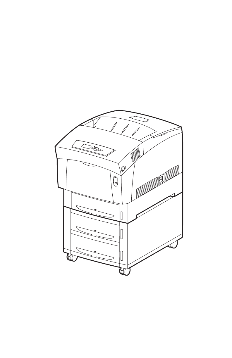
The Xerox Phaser® 6200 Color Laser Printer Service Manual is the primary
document used for repairing, maintaining and troubleshooting the printer.
To ensure complete understanding of the product, participation in Xerox Phaser 6200
Service Training is recommended.
S6200-001
Phaser 6200 Color Laser Printer shown with the optional High-Capacity Feeder
General Information 1
Page 16

Phaser 6200 Color Laser Printer Overview
The Phaser 6200 Color Laser Printer combines a single-pass, tandem color laser
design with an image processor supporting PostScript 3 and PCL5c. The Phaser 6200
is a high performance, A4, 16 ppm desktop color laser printer with a resolution up to
2400 x 600 dpi.
The Phaser 6200 has four configurations. The main difference is optional networking,
standard memory, optional High-Capacity Feeder (HCF), duplexing and optional
internal hard drive.
A replaceable “Configuration Upgrade Chip” holds configuration information that
enables or disables built-in features as described below.
Phaser 6200B The Phaser 6200B is a base configuration, entry-level, single pass
color laser printer. The printer comes standard with 64 Mbytes of memory, resolution
of 600 x 600 dpi, USB and Parallel support, a built in Multi-Purpose Tray and a
500-sheet universal paper tray.
Phaser 6200N The Phaser 6200N is the networking configuration. This
configuration includes all the features of the 6200B, but comes with 128 Mbytes of
memory, built-in 10/100 Ethernet networking capabilities, job pipelining, enhanced
print mode and a resolution up to 2400 x 600 dpi.
Phaser 6200DP The Phaser 6200DP is the plus configuration. The printer includes
all the features of the 6200N, but comes standard with 128 Mbytes of memory, builtin auto-duplexing, PDF and Photo Mode support.
Phaser 6200DX The Phaser 6200DX is the marketing configuration. The printer
includes all the features of the 6200DP, but comes standard with 256 Mbytes of
memory, a 1000-sheet High-Capacity Feeder Assembly with wheels and an internal
10+ Gbyte hard drive.
Page Description Languages (PDL)
■ PCL5c (not available on the Phaser 6200B)
■ Adobe PostScript 3
■ PDF (not available on the Phaser 6200B, requires internal hard drive)
Resident Fonts
■ 136 PostScript Type 1
■ 115 Central European PostScript Type 1
■ 46 PCL fonts (more fonts are available with the optional internal hard drive)
2 Phaser 6200 Color Laser Printer - Service Manual
Page 17

Proof Jobs. A proof job is a specific case of a multiple-copy job. With a proof job, the
customer assigns a password and copy count at the client workstation before printing. The
first set of prints are printed immediately. The original number of requested sets are
printed after the customer enters the matching password on the printer’s control panel. The
customer has the option of printing the original number of requested sets or deleting the
job. Since more than one job may be associated with the same password, the customer can
print all the jobs, delete all the jobs, or select or delete individual jobs. A proof job that has
not been printed is retained on the optional internal hard drive through power cycles.
Secure Jobs. Secure printing allows the customer to defer printing of a job until a
matching password is entered from the control panel. The customer assigns the password
at the client workstation before printing. The job is stored, and printing is delayed until the
password is entered on the printer’s control panel. Since more than one job can have the
same password, all secure jobs with the same password are printed. A secure job that has
not been printed or released is retained on the internal hard drive through power cycles.
Saved Jobs. Saved print allows the user to save print jobs to the internal hard drive of
the printer. The print job is not deleted after printing, it is stored on the hard drive for print
on demand. This function requires an internal hard drive.
Printer Memory and RAM Capabilities
The printer features two slots which accept 64, 128 and 256 Mbyte of SDRAM. All
combinations are allowed for 64, 128, 192, 256, 320, 384 and 512 Mbytes.
■ PC133 DRAM Standard
■ 144 Pin SODIMM
■ Serial Presence Detect
■ 3.3 Volt
The Startup Page and the Configuration Page list the amount of RAM installed in the
printer.
If the memory does not meet the above specifications, it will be ignored by the printer.
General Information 3
Page 18

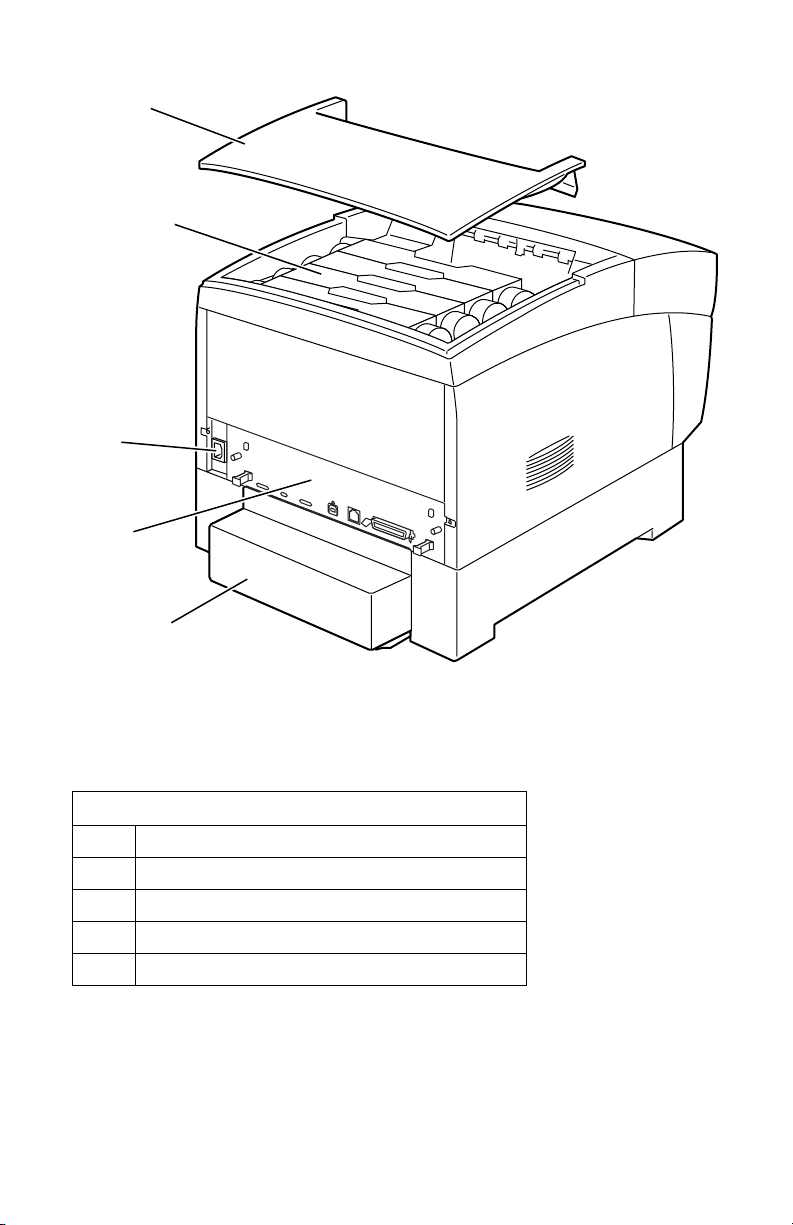
Parts of the Printer
1
2
7
8
3
4
5
9
6
S6200-005
No. Description
1 Top Cover (Output Tray)
2 Control Panel (Front Panel)
3 Front Cover
4 Multi-Purpose Tray
5 Universal Paper Tray 1
6 High-Capacity Feeder with Tray 2 and Tray 3
7 Door Latch B
8 Door Latch A
9 Power On/Off Switch
4 Phaser 6200 Color Laser Printer - Service Manual
Page 19
1
2
3
4
5
S6200-006
No. Description
1 Top Cover
2 Toner Cartridge
3 AC Power Cord Plug
4 Image Processor Board
5 Paper Tray Rear Cover
General Information 5
Page 20
1 23
S6200-008a
43
S6200-008b
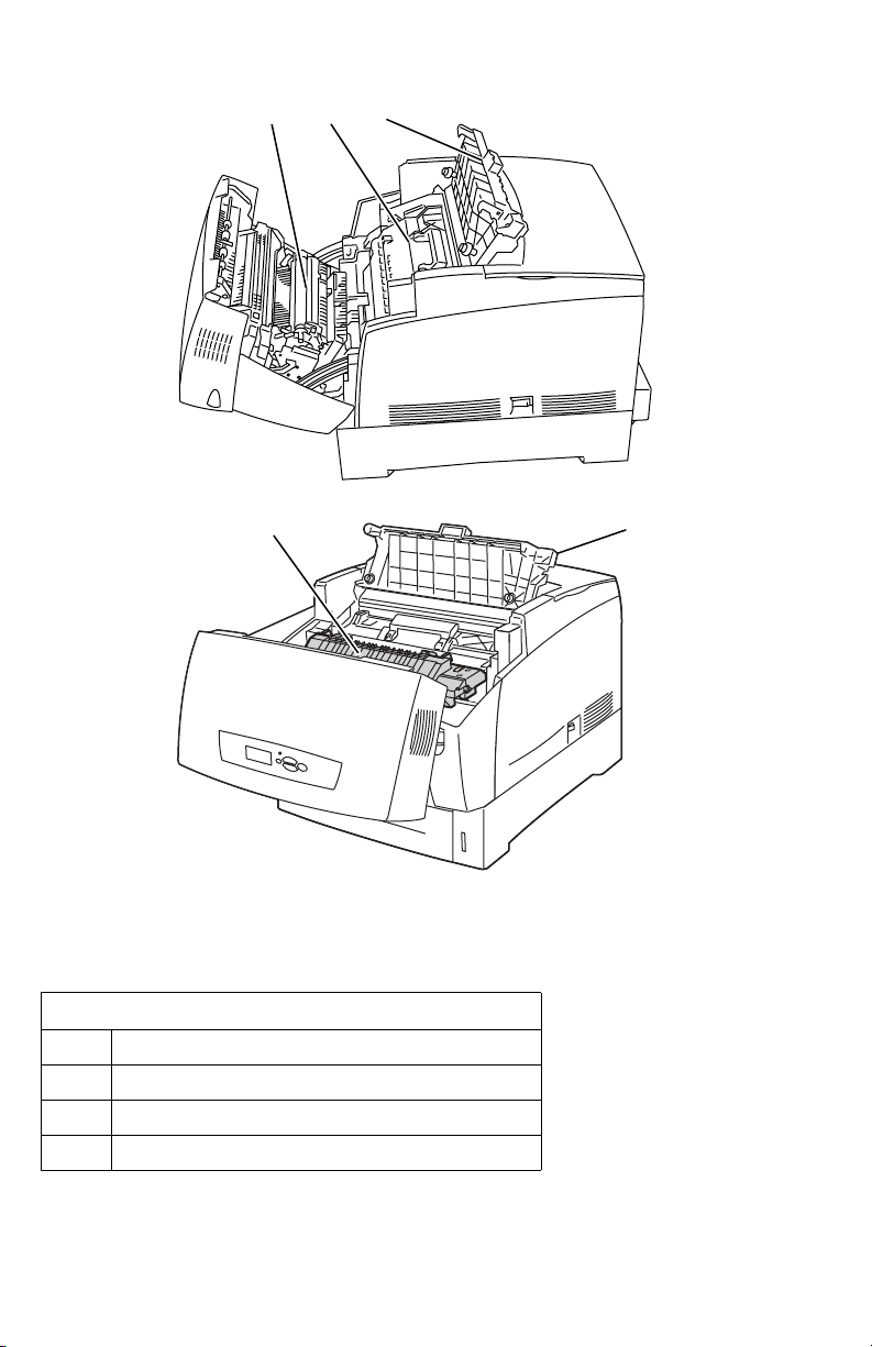
No. Description
1 Transfer Roller
2 Imaging Unit
3 Door C
4 Fuser Assembly
6 Phaser 6200 Color Laser Printer - Service Manual
Page 21

CRC Life Counter Behavior
Internal counters track Customer-Replaceable Consumables (CRCs) life usage and
store the values in NVRAM. The image processor board monitors these counters in
order to display the near end-of-life and end-of-use messages.
Life ratings are based on 5% coverage. Imaging Unit average 4 page job length.
.
Customer-Replaceable Consumable (CRC) Print Life
Toner Cartridges*
*(Black Toner Cartridge Standard Capacity is 4,000)
Imaging Unit
Fuser Assembly
Transfer Roller and Waste Box
Customer-Replaceable Unit (CRU)
Feed Roller Kit
High-Capacity 8,000 (B50)
Standard-Capacity 3,000
30,000 (B50)
60,000 (B10)
15,000 (B50)
up to 100,000
General Information 7
Page 22
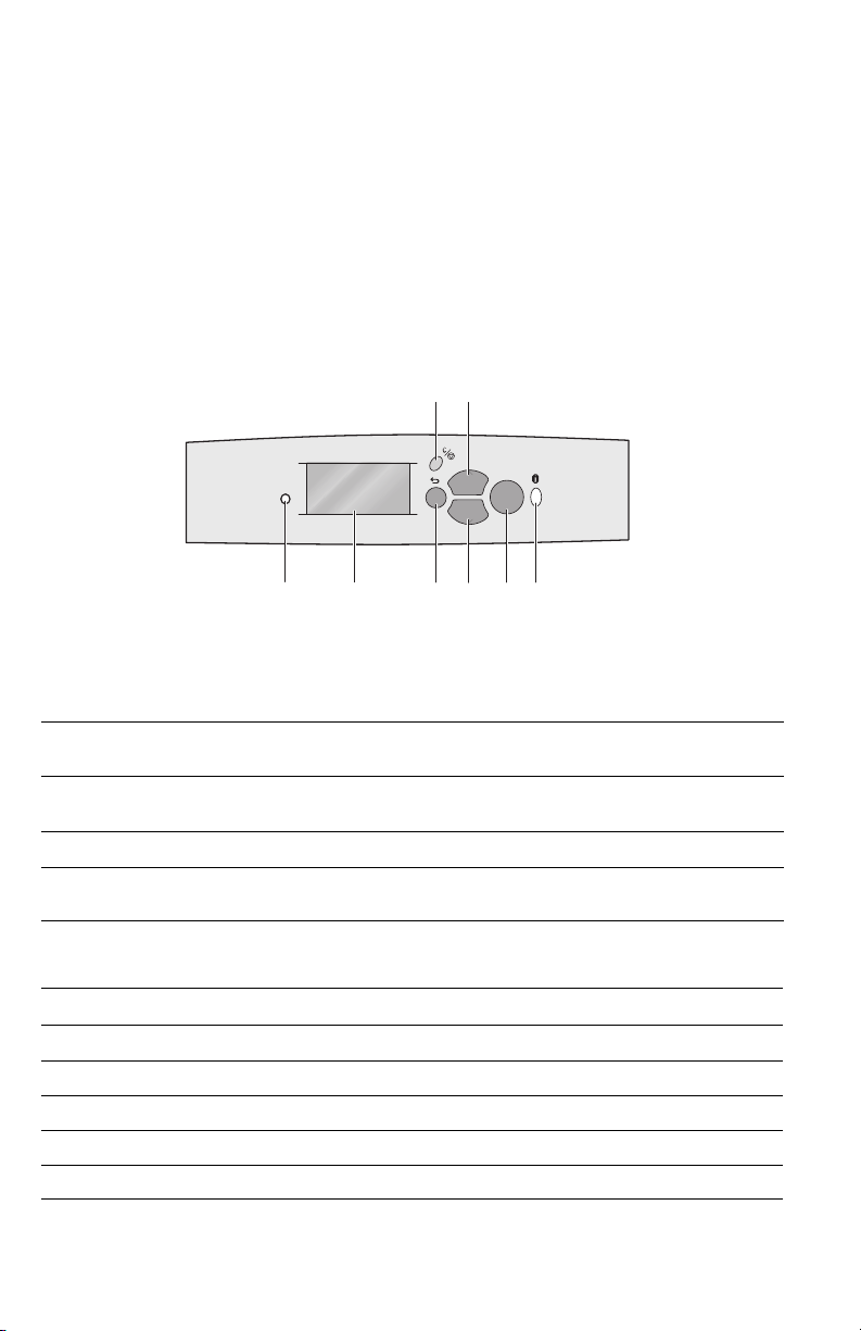
Front Panel Configuration
The Front Panel consists of one tricolor LED, a display window and six functional
keys. These keys navigate the menu system, perform functions and select modes of
operation for the printer.
LED indicators:
■ Green = Ready to Print or Printing
■ Flashing Green = Receiving, Processing Data, Printing or Power Saver Mode
■ Flashing Yellow = Warning
■ Flashing Red = Error
Phaser 6200
12345678
OK
S6200-004
Phaser 6200 Front Panel Configuration
Front Panel Key Descriptions
LED (Power/Status)
1
Graphic front panel display
2
Cancel Key
3
Back Key
4
Up Arrow Key - scrolls up the menu
5
system
Down Arrow Key - scrolls down the
6
menu system
OK (select) Key
7
Information Key - for additional
8
explanation or help
Front Panel Shortcuts
Mode Press this selection at Power On
Skip execution of POST diagnostics OK
Print Service Diagnostics Map INFO
Reset PostScript NVRAM BACK+OK
Password Bypass UP+DOWN
Enter Service Diagnostics BACK+INFO
8 Phaser 6200 Color Laser Printer - Service Manual
Page 23

Image Processor Board
The following components need to be transferred from the old board when installing a
new Image Processor Board in the printer. See RRP 12.8 for information on replacing
the Image Processor Board.
pin 1
1 2 3 4
Top View
No. Description
1 Hard Drive (optional)
2 Configuration Upgrade Chip (“i” Button)
3 NVRAM
4 Memory (RAM) DIMM 1 and DIMM 2
S6200-270
Rear Panel Configuration Interfaces
■ IEEE 1284 Parallel
■ Ethernet 10BaseT and 100BaseTx
■ USB
General Information 9
Page 24
Printer Specifications
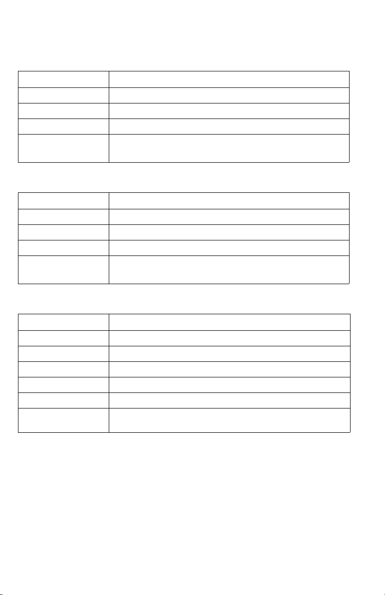
Physical Dimensions - Printer
Dimensions Value
Height: 445 mm (17.52 in.)
Width: 439 cm (17.28 in.)
Depth: 638 mm (25.12 in.)
Weight: Approximately 36.5 kg (80.5 lb.) Print engine
Approximately 56.5 kg (124.5 lb.) with Paper Tray(s) installed
Physical Dimensions - Optional High-Capacity Feeder
Dimensions Value
Height: 336 mm (13.23 in.) Optional Paper Tray Assembly
Width: 439 cm (17.28 in.)
Depth: 563 cm (22.17 in.)
Weight: Approximately 15 kg (33 lb.) no Paper Tray(s) installed
Approximately 20 kg (44 lb.) with Paper Tray(s) installed
Printer Clearances
Clearances Value
Top: 350 mm (13.78 in.)
Left: 100 mm (3.94 in.)
Right: 150 mm (5.91 in.)
Front: 600 mm (23.62 in.)
Rear: 200 mm (7.87 in.)
Mounting surface level
tolerance:
Within 3 degrees of horizontal with all four feet in contact with the
surface.
10 Phaser 6200 Color Laser Printer - Service Manual
Page 25

Functional Specifications
Functional Specifications
Characteristic Specification
Printing process Imaging System - 4-tandem drums, electro-photographic system
Color medium Cyan, Magenta, Yellow and Black Toner Cartridges
Resolution /
Addressability
Operating Modes Running Mode: Print Engine capable of making prints immediately.
Continuuous Operating
Printing Speed
ppm = pages per minute
ipm = image per minute
using intermediate drum transfer rolls (IDTs).
Exposure System - Semiconductor laser, simultaneous scanning
by 4 beams.
Development System - Dry type 2-component developer.
Fusing System - Heat fusing, free nip-belt system.
Standard & Draft 600 x 600 dpi
Enhanced 2400 x 600 dpi* (Factory Default)
Photo 1200 x 1200 dpi**
* Not available on the Phaser 6200B.
** Not Available on the Phaser 6200B or Phaser 6200N.
Ready Mode: 20 seconds from completion of a print.
Sleep/ Low Power/ Power Saver Mode: entered after a specified
period of Print Engine inactivity since completion of the last print.
Mode Paper Size / wt g/m
600 dpi Letter / A4
65 -105 16 ppm 10 ipm
100-159 8 ppm N/A
160-216 8 ppm N/A
1200/2400 dpi Letter / A4
65 -105 8 ppm 5 ipm
100-159 8 ppm N/A
160-216 8 ppm N/A
2
Simplex Duplex
Cleaning Cycle interval
for continuous printing
600/1200 dpi Envelope/Postcard
Mode OHP
600 dpi Letter / A4 8 ppm N/A
1200 dpi Letter / A4 8 ppm N/A
Print speed will be reduced if the print job is larger than the cleaning
cycle interval.
IU Print Volume Standard/Draft Enhanced/Photo
0 - 5 K Pages 48 24
5 - 10 K Pages 32 16
10 - 15 K Pages 32 16
15 - 20 K Pages 32 16
20 - 25 K Pages 20 10
25 - 30 K Pages 16 8
160-216 8 ppm N/A
pages pages
General Information 11
Page 26

Functional Specifications (cont'd.)
Characteristic Specification
First Print-Out
(in seconds)
(Letter/A4)
Warm-up time 30 seconds from cold start (power off condition)
Mode Tray 1 Tray 2 Tray 3 MPT
Simplex, 600 dpi 15 16.5 18 14.5
Duplex, 600 dpi 23.5 25 26.5 23
Simplex, 1200 dpi 24.5 27.5 30.5 23.5
Duplex, 1200 dpi 39.5 42.5 45.5 38.5
Electrical Specifications
Electrical specifications
Characteristic Specification
Primary line voltages 100-120 V Printer - (97 - 132 V) 13 amp circuit
220-240 V Printer - (198 - 264 V) 7-8 amp circuit
Primary line voltage
frequency range
Power consumption Mode Condition 100/115 VAC 240 VAC
100-120 V Printer - 50/60 Hz + 2 Hz
220-240 V Printer - 50/60 Hz + 2 Hz
Print Mode Max. 850 W or less 850 W or less
Ready Mode Fuser On 180 W or less 180 W or less
Sleep Mode Fuser Off 45 W or less 45 W or less
12 Phaser 6200 Color Laser Printer - Service Manual
Page 27

Environmental Specifications
Environmental Specifications
Characteristic Specification
Temperature:
Operating
Transportation
Storage
24 month maximum
1 month maximum
Humidity
Operating
Transportation
Storage
Altitude
Operating
Transportation
Acoustic Noise
Idle
Printing
Optimal print-quality range: 62o to 80o F (17o to 26o C)
10o C to 32o C (50o F to 90o F)
-30o C to +50o C (-22o F to 122o F)
Normal: 0o C to 35o C (32o F to 95o F)
Severe: -20o C to 40o C (-4o F to 104o F)
Optimal print-quality range: 35% to 70%
10% - 85%
30% - 85%
5% - 95%
0 - 2,500 meters (8,000 ft.)
0 - 6,092 meters (20,000 ft.)
35.0db or less
53.0db or less (Full Speed) (5.3 B)
70.0db or less (Half Speed) (7.0 B)
General Information 13
Page 28

Media and Tray Specifications
Media and Tray Specifications
Specification Trays
Printable
Area
Usable
paper sizes
Supported
paper
types and
weights
Supported
envelopes
Specialty
Media
Minimum margins = 5 mm (0.2 in.) on all sides
Maximum paper size = 215.9 mm x 355.6 mm (8.5 in. x 14 in.)
Minimum paper size = 88.9 mm x 139.7 mm (3.5 in. x 5.5 in.)
Paper Type Size
Letter 8.5 x 11 in.
Legal 8.5 x 14 in.
Executive 7.25 x 10.5 in.
Statement 5.5 x 8.5 in.
US Folio 8.5 x 13 in.
A4 210 x 297 mm
A5 148 x 210 mm
A6 105 x 148 mm
B5 JIS 182 x 257 mm
ISO B5 176 x 250 mm
Custom Size
Type Weight
Plain Paper 64 - 90 g/m2 (17 - 24 lb. Bond)
Heavy Plain Paper 85 - 105 g/m
Phaser 6200 Transparency ONLY
Thin Card Stock 100 - 163 g/m
Thick Card Stock 160 - 216 g/m
Labels N/A
Letterhead 85 - 105 g/m
Glossy Coated Paper 120 - 163 g/m
Business and Greeting Card N/A
CD/DVD Labels and Inserts N/A
Digital Photo Paper 120 - 163 g/m
Envelopes Weight 20 - 24 lb. Bond
Commercial #10 4.12 x 9.5 in
Monarch Envelope 3.87 x 7.5 in
A7 Envelope 5.25 x 7.25 in
Custom
DL Envelope 110 x 220 mm
C5 Envelope 162 x 229 mm
C6 Envelope 114 x 162 mm
B5 Envelope 176 x 250 mm
Envelopes with hot melt type glue are not supported in this
printer.
Premium Phaser 6200 Transparencies
Letter 216 x 279 mm 8.5 x 11 in.
A4 210 x 297 mm 8.27 x 11.69 in.
Other sizes will be handled through the Multi-Purpose Tray with
use of the custom size option.
2
(22 - 28 lb. Bond)
2
(26 - 60 lb. Cover)
2
(59 - 80 lb. Cover)
2
(22 - 28 lb. Bond)
2
(81 - 110 lb. Book
2
(81 - 110 lb.)
All Trays
All Trays
All Trays
All Trays
MPT Only
All Trays
All Trays
MPT Only
MPT Only
All Trays
MPT Only
MPT Only
All Trays
All Trays
MPT & Tray 1
MPT Only
MPT Only
MPT Only
All Trays
MPT Only
MPT Only
MPT Only
MPT Only
MPT Only
MPT and
Tray 1 Only
14 Phaser 6200 Color Laser Printer - Service Manual
Page 29

Media and Tray Specifications (cont'd.)
Specification Trays
Tray
Capacity
Standard Paper 500 Sheets 100 Sheets
Transparency* 100 Sheets* 50 Sheets
Envelopes N/A 10 each
Universal Tray MPT
*Tray 1 / MPT
only
General Information 15
Page 30

Error Messages and Codes
This section covers troubleshooting procedures for the Phaser 6200 Color Laser
Printer’s front panel error messages and codes. Only jams and fatal errors will
produce an associated numeric code. Error messages and codes are generally specific,
making it important that service personnel and users record errors exactly when
reporting problems with the printer. Any code associated with an error message or
jam can be viewed by pressing the INFO key and scrolling to the bottom of the help
text displayed on the front panel.
Some procedures require running service diagnostic test functions to verify a specific
printer part is operating correctly. For information on Service Diagnostics and all
internal printer test functions, see the table "Service Diagnostics" on page 23
To troubleshoot problems, such as start up and power on, media, paper path,
print-quality or image problems, and electrical failures not associated with a front
panel message or code, refer to the section "Troubleshooting" on page 81.
If an error message or code is not visible on the front panel, the usage profile report
and fault history list errors reported by the printer.
When an error first occurs, record the error message and code then cycle power to the
printer to see if the error recurs. These can be accessed one of three ways:
Accessing Fault History
1. Print (if possible) the Usage Profile Report Log from the printer’s front panel
Support Menu. The fault history will be detailed in this report log.
2. View the printer’s fault history on the front panel. a. Go to Support Menu --> Service Tools --> Fault History.
3. If the printer is connected to a network and has a TCP/IP address, view the
printer’s web page using a web browser.
a. Open a web browser.
b. Enter the printer’s IP address as the URL.
c. Select the Troubleshoot link and the fault history will be displayed.
Error Messages and Codes 17
Page 31

Contents
Front Panel Message Page
Jam Errors
Jam at Fuser Code: Jam F
Jam at Duplex Code: Jam D
Jam at Registration Roller Code: Jam RR
Misfeed at MPT Code: Jam T0
Misfeed at Tray 1 Code: Jam T1
Misfeed at Tray [2] Code: Jam T2
Misfeed at Tray [3] Code: Jam T3
Door and Cover Errors
Close Front Door
Consumable Errors
Install or Reseat Imaging Unit
Replace Imaging Unit or Imaging Unit is at End of Life
Install or Reseat Transfer Roller
Replace Transfer Roller or Transfer Roller is at End of Life
Install or Reseat Fuser
Replace Fuser or Fuser is at End of Life
Install or Lock [Y] [M] [C] [K] Toner Cartridge
Replace [Y] [M] [C] [K] Toner Cartridge or
[Y] [M] [C] [K] Toner Cartridge Empty
Dusty Density Sensor
Tray and Media Errors
Output Tray is Full, Unload Paper
Insert Tray 1 or Tray 1 missing
Insert Tray [2] [3] or Tray [2] [3] missing
Tray 1 Paper is Low
Tray [2] [3] Paper is Low
MPT Empty, Load Paper
Tray [1] [2] [3] Empty, Load Paper
31
33
35
37
40
43
47
48
49
50
51
52
53
54
55
57
58
59
60
61
62
63
64
18 Phaser 6200 Color Laser Printer - Service Manual
Page 32

Contents (cont'd.)
Front Panel Message Page
Media Mismatch Errors
Load Tray 1 with [size] [type]
Load Tray [2] [3] with [size] [type]
Front Panel Fatal Error Messages and Codes
Laser Failure Code: 07, 08, 09, 10, 11
Density Sensor Failure or
Low Density Failure Code: 12, 13, 14, 15, 16
Fuser Failure Code: 40, 41, 42, 43, 44, 45, 46, 47
Fuser Fan Failure Code: 50
Rear Fan Failure Code: 51
Generic Fan Failure Code: 52
Engine Firmware Failure Code: 70, 71, 72, 73, 74, 77, 78, 79
Imaging Unit Firmware Failure Code: 75
Fuser Firmware Failure Code: 76
Engine Firmware Failure Code: 77, 78
Controller to Engine
Communications Failure Code: 81
NVRAM Failure Code: 83
Non-Xerox Imaging Unit Code: 95
Environment Sensor Failure Code: 102
65
66
68
69
70
73
74
75
76
77
72
76
78
78
79
80
Error Messages and Codes 19
Page 33

Service Flowchart
The Service Flowchart outlines one possible approach to troubleshooting and repair
of the printer. The Service Flowchart is an overview of the path a service technician
could
take, using this technical manual, to service the print engine and options. If you
choose not to use the Service Flowchart, it is recommended that you start at the
appropriate troubleshooting table and proceed from there.
Always follow the safety measures detailed in the front of the manual when servicing
the printer. See "Service Safety Summary" on page vi of this manual.
Step 1: Identify the Problem:
1 Verify the reported problem does exist. 2 Check for any error codes and write them down. 3 Print normal customer prints and service test prints. 4 Make note of any print quality problems in the test prints. 5 Make note of any mechanical or electrical abnormalities present. 6 Make note of any unusual noise or smell coming from the printer. 7 Print a Usage Profile Report, if the printer is able to print. 8 View the fault history under the Service Tools Menu 9 Verify the AC input power supply is within proper specifications by measuring the
voltage at the electric outlet while the printer is running.
Step 2: Inspect and Clean the Printer:
1 Switch OFF printer power. 2 Disconnect the AC power cord from the wall outlet. 3 Verify the power cord is free from damage or short circuit and is connected properly. 4 Remove the Imaging Unit and protect it from light. 5 Inspect the printer interior and remove any foreign matter such as paper clips,
staples, pieces of paper, dust or loose toner.
■ Do not use solvents or chemical cleaners to clean the printer interior.
■ Do not use any type of oil or lubricant on printer parts.
■ Use only an approved toner vacuum.
6 Clean all rubber rollers with a lint-free cloth, dampened slightly with cold water and
mild detergent.
7 Inspect the interior of the printer for damaged wires, loose connections, toner
leakage, and damaged or obviously worn parts.
8 If a toner cartridge appears obviously damaged, replace with a new one.
Step 3: Find the Cause of the Problem:
1 Use the Error Messages and Codes and troubleshooting procedures to find the
cause of the problem.
2 Use Diagnostics to check printer and optional components.
3 Use the Wiring Diagrams and Plug/Jack Locator to locate test points.
4 Take voltage readings at various test points as instructed in the appropriate
troubleshooting procedure.
5 Use the “Engine Test Print”, page 96, to isolate problems with the Image Processor
Board.
Step 4: Correct the Problem
1 Use the Parts List to locate a part number 2 Use the Removal and Replacement Procedures to replace the part.
Step 5: Final Checkout
1 Test the printer to be sure you have corrected the initial problem and there are no
additional problems present.
20 Phaser 6200 Color Laser Printer - Service Manual
Page 34

Using the Troubleshooting Procedures
1. Each Step in a Troubleshooting Procedure instructs you to perform a certain action
or procedure. The steps are to be followed sequentially in the order given until the
problem is fixed or resolved.
2. The Actions and Questions box contains additional information and/or additional
procedures you must follow to isolate the problem.
3. When a procedure instructs you to test a component using service diagnostics, See
"Service Diagnostics" on page 23 for the detailed steps and functions for testing
parts of the printer.
4. The action is followed by a question. If your response to the question is “Ye s” ,
then follow the instructions for a “Ye s ” reply. If your response to the question is
“No”, then follow the instructions for a “No” reply.
5. Troubleshooting Procedures may ask you to take voltage readings or test for
continuity at certain test points within the printer. For detailed diagrams, refer to
the section "Plug/Jack Locator Maps" on page 341 and "Wiring Diagrams" on
page 351 for complete information on test point locations and signal names.
6. Troubleshooting Procedures often ask you to replace a printer component. The
section "FRU Disassembly - Removal and Replacement Procedures" on page 119
provides detailed steps for removing and replacing all major parts of the printer.
The section "FRU Parts List" on page 253 details the location, quantity and part
number for all spared parts of the printer.
General Notes on Troubleshooting
1. Unless indicated otherwise, the instruction “switch ON printer main power” means
for you to switch ON printer power and let the printer proceed through POST to a
‘Ready’ condition.
2. Conventions used to represent connectors
Plug Jack
S6200-282
3. When instructed to take voltage, continuity or resistance readings on wiring
harness, proceed as follows; Check P/J 232–1 to P/J 210–5 by placing the red
probe (+) of your meter on pin 1 of P/J 232, and place the black probe (–) of your
meter on pin 5 of P/J 210.
4. When you are instructed to take resistance readings between “P/J 232 <=> P/J
210” (without specified pin numbers), check all pins. Refer to the the section
"Wiring Diagrams" on page 351 for the location of all wiring harnesses and pins.
5. When you are instructed to take a voltage reading, the black probe (–) is generally
connected to a pin that is either RTN (Return) or SG (Signal Ground). You can
substitute any RTN pin or test point in the printer, and you can use FG (frame
ground) in place of any SG pin or test point.
6. Before measuring voltages make sure the printer is switched ON, the Imaging Unit
and the paper trays are in place, and the interlock switches are actuated, unless a
troubleshooting procedure instructs otherwise.
Error Messages and Codes 21
Page 35

7. All voltage values given in the troubleshooting procedures are approximate
values. The main purpose of voltage readings is to determine whether or not a
component is receiving the correct voltage value from the power supply and if
gating (a voltage drop) occurs during component actuation. Gating signals may be
nothing more than a pulse, resulting in a momentary drop in voltage that may be
difficult or impossible to read on the average multi-meter.
8. When a troubleshooting procedure instructs you to replace a non-spared
component and that component is part of a parent assembly, you should replace
the entire parent assembly.
Voltage Measurements
Power and signal grounds are connected to the frame ground. All circuit
troubleshooting can be performed using the metal frame (chassis) as the grounding
point. To locate connectors or test points, refer to the section "Plug/Jack Locator
Maps" on page 341 or "Wiring Diagrams" on page 351 for more information.
Unless otherwise specified, the following voltage tolerances are used within this
section:
Voltage Measurements
Stated Measured
+3.3 VDC +3.135 to +3.465 VDC
+5.0 VDC +4.75 to +5.25 VDC
+24.0 VDC +21.6 to +26.4 VDC
0.0 VDC Less than +0.5 VDC
22 Phaser 6200 Color Laser Printer - Service Manual
Page 36

Service Diagnostics
The Phaser 6200 Color Laser Printer has built-in diagnostics to aid in troubleshooting
problems with the printer. The Service Diagnostics Menu provides a means to test
sensors, motors, switches, clutches, fans and solenoids. Diagnostics also contain
built-in test prints, cleaning procedures, printer status and some NVRAM access.
Service diagnostics are to be executed by a service technician only, through the front
panel. Service Diagnostics can be entered one of two ways:
Entering without rebooting the printer:
1. From the printer’s main menu, scroll to the Support Menu, press OK and then
scroll to the
2. Hold down the Up Arrow key and press the Down Arrow key.
3. Scroll to Run Service Diagnostics and press OK.
Entering by reboooting the printer:
1. Turn the printer power OFF.
2. Hold down the Back and Information keys simultaneously and turn the printer
back ON.
3. Continue to hold the keys until the following mesage is displayed on the front
panel:
the keys.
4. The front panel displays the Service Diagnostics Menu.
You can print a Service Diagnostics Menu Map by highlighting Print Service
Diagnostics Menu
Ready. You will need to re-enter service diagnostics.
Service Tools Menu and press OK.
Service Diagnostics V#.##, Initializing..., and then release
, and press OK. The printer will run through POST and return to
Service Diagnostics Key Press and Function Table
Key Function
BACK Returns to the prior higher level menu structure, if available.
If help text is displayed on the front panel, pressing BACK will restore the current
menu item and remove the help text.
CANCEL Terminates the current test.
Cancels current INFO display.
INFO Provides help information, if available.
Pressing INFO again restores the current menu item and removes the help text.
UP Scrolls up one menu item within a menu list. This control does not ‘wrap’.
Used to increment data in tests requiring user input.
DOWN Srolls down one menu item within a menu list.
This control does not ‘wrap’, the end of a menu list is designated by three
asterisks.
Used to decrement data in tests requiring user input.
OK Enters the highlighted menu. Executes the current test item.
Error Messages and Codes 23
Used to select a data value entered by the user.
Page 37

Service Diagnostics Tests and Functions Table
Tes t Front Panel Display and Test Definition
Print Service Menu Map - Prints the service diagnostics menu page
General Status - Provides the following print engine status:
Status
Engine Board
ROM Version
Printer
Configuration
Ambient
Temperature/
Humidity
Fuser
Temperature
Fault History
Test Prints - Prints test prints stored in the Engine Control Board. The prints are used by
service personnel to identify, repair and validate the operability of the printer.
Blank Page
Print
600 x 600 Test
Pattern
<No Status to Report> No Status to Report = the printer is
Engine FW: #.#.# Displays the engine firmware
Memory: ###MB
Hard Drive: Not Installed or
Installed
HCF: Installed
Not Installed
Temperature: XX oC
Humidity: ## %
Temperature: XX oC Displays the printers current Fuser
Device Status
Jams
Hardware Errors
Firmware Errors
Fan Motors
CTD Sensor Errors
Fuser Failure
Laser Failure
Life Over
Trays
Miscellaneous
Continuously prints blank pages until
stopped by the user.
Continuously prints the step pattern
until stopped by the user.
online and ready to print.
Displays an engine status that will
prevent printing. Status is displayed
sequentially, on line at a time.
version installed.
Displays current memory installed.
Detects presence of Hard Drive
option.
Detects presence of High-Capacity
Feeder option.
Displays the current Temperature
and Humidity for the printer.
temperature.
Displays Fault occurrence since last
power cycle.
See "Test Prints, Adjustments and
NVRAM" on page 109, for specific
test print information.
24 Phaser 6200 Color Laser Printer - Service Manual
Page 38

Service Diagnostics Tests and Functions Table (cont'd.)
Test Front Panel Display and Test Definition
Motors/Fans Tests - Tests the functionality of motors and fans by giving service personnel the
ability to energize/de-energize the motor and fans one at a time.
Main Motor
Duplex Motor
Fuser Motor
Developer
Motor
Caution:
Do NOT allow
this motor to run
any longer than
necessary to
verify operation.
HCF Motor
Toner Motor
Yellow
Toner Motor
Magenta
Toner Motor
Cyan
Toner Motor
Black
Rear Fan
Normal Speed
Half Speed
Normal Speed Continuous
Half Speed Continuous
Forward Normal Speed
Forward Half Speed
Forward Double Speed
Reverse Normal Speed
Reverse Half Speed
Reverse Double Speed
Forward Normal Speed Contiuous
Forward Half Speed Contiuous
Forward Double Speed Contiuous
Reverse Normal Speed Contiuous
Reverse Half Speed Contiuous
Reverse Double Speed Contiuous
Normal Speed
Half Speed
Normal Speed Continuous
Half Speed Continuous
Normal Speed
Half Speed
Normal Speed
Half Speed
Normal Speed Continuous
Half Speed Continuous
Normal Speed Audible verification of motor
High Speed
Low Speed
High Speed Continuous
Low Speed Continuous
Audible verification of motor
functionality.
The motor tests are pulsed or
continuous.
Audible verification of motor
functionality.
Audible verification of motor
functionality.
Audible verification of motor
functionality.
Caution: Only run the developer
motor test once per power cycle to
avoid excessive amounts of toner
being forced inside the developer
resulting in possible damage.
Audible verification of motor
functionality.
functionality.
Caution: Only run the Toner Motor
tests once per power cycle to avoid
toner spillage inside the Imaging
Unit cavity and packing the auger
tubes with toner.
Audible verification of motor
functionality.
Check for airflow.
Error Messages and Codes 25
Page 39

Service Diagnostics Tests and Functions Table (cont'd.)
Test Front Panel Display and Test Definition
Fuser Fan
Sensor/Switch Tests - Tests the functionality of the sensors and switches by giving service
personnel the ability to input actuation and state changes of all sensors and switches.
Interlock
Switch
Registration
Sensor
Exit Sensor
Duplex
Sensor
Full Stack
Sensor
Black Toner
High Speed
Low Speed
High Speed Continuous
Low Speed Continuous
Sensor is: ON
Sensor is: OFF
Sensor is: OFF
Sensor is: ON
Sensor is: OFF
Sensor is: ON
Sensor is: OFF
Sensor is: ON
Sensor is: OFF
Sensor is: ON
Toner is [NOT] Low Displays current state of the sensor.
(K) Low
Cyan Toner
(C) Low
Magenta
Toner (M) Low
Yellow Toner
(Y) Low
Black Toner
Cartridge
Present
Cyan Toner
Cartridge
Sensor is: OFF
Sensor is: ON
Present
Magenta
Tone r
Cartridge
Present
Yellow Toner
Cartridge
Present
Audible verification of motor
functionality.
Check for airflow.
Front Door OPEN
Front Door CLOSED
This test continuously cycles paper
through the printer.
The sensor state changes from off
to on as the paper passes through
the Registration Chute.
Note: This test can also be used as
a paper path transport test when
troubleshooting Jam conditions.
Actuate/de-actuate the Exit
Actuator (PL8.1.7) located in the
Fuser to toggle the sensor state.
Actuate/de-actuate the Duplex
Actuator (PL6.1.13) located in the
Fuser to toggle the sensor state.
Actuate/de-actuate the Output Tray
Full Actuator (PL6.1.4) at the output
tray to toggle the sensor state.
Toggle the toner cartridge switch for
the appropriate color.
Toner Cartridge is in the LOCKED
position.
Toner Cartridge is in the
UNLOCKED position.
26 Phaser 6200 Color Laser Printer - Service Manual
Page 40

Service Diagnostics Tests and Functions Table (cont'd.)
Test Front Panel Display and Test Definition
Tray 1 Low
Paper
Tray 2 Low
Paper
Tray 3 Low
Paper
Tray 1 No
Paper
Tray 2 No
Paper
Tray 3 No
Paper
MPT No Paper
Sensor
Transfer
Roller Toner
Full Sensor
Image Unit
Not Installed
Sensor
Fuser Fan
Alarm Sensor
Rear Fan
Alarm Sensor
CTD (ADC)
Sensor
OHP Sensor
Size: XXXX
Paper is Not Low
Paper is Low
Paper is Not Present
Paper is Present
Paper is Not Present
Paper is Present
Toner Waste [Not] Full Block the Toner Full Sensor
Image Unit is [Not] Present Open Door C to change the state of
Fuser Fan Alarm Sensor is: OK
Failure
Rear Fan Alarm Sensor is:
OK
Failure
Dark Value: #
Light Value: ###
Sensor OK
OHP
Absense of Media
Paper
Move the Rear Guide in the paper
tray to the desired paper size and
verify the sensor output matches
the paper size selected.
Insert and fill Tray [1] [2] [3] with
paper to the fill line.
Insert one sheet of paper in Tray [1]
[2] [3] to change the sensor state.
Insert Tray [1] [2] [3] with an
adequate amount of paper.
Toggle the No Paper Actuator.
Insert Paper into the MPT Tray.
Toggle the MPT No Paper Actuator
(PL6.1.37) to change the state.
(PL5.1.13) to change the sensor
state.
the Switch.
Status only
Note: Perform a test print
immediately prior to performing this
test.
Status only
Note: Perform a test print
immediately prior to performing this
test.
Status only
Remove the transfer roller to
observe change of state.
Reports “Paper” if opaque media is
present.
Reports “OHP or Absence of Media
if OHP or no media is present.
Manually insert a sheet of paper
backwards through the Registration
Chute Assembly (PL9.1.6) until the
state of the sensor changes to
“Paper”.
Error Messages and Codes 27
Page 41

Service Diagnostics Tests and Functions Table (cont'd.)
Test Front Panel Display and Test Definition
Clutch Tests - Tests the functionality of the clutches by giving service personnel the ability to
energize/de-energize one clutch at a time.
Registration
Clutch
MPT Turn
Clutch is: ON
Clutch is: OFF
Clutch
Tray 1 Turn
Clutch
Tray 2 Turn
Clutch
Tray 3 Turn
Clutch
Solenoid Tests - Tests the functionality of the clutches by giving service personnel the ability to
energize/de-energize one solenoid at a time.
MPT Turn
Clutch
Tray 1 Turn
Solenoid is: ON
Solenoid is: OFF
Clutch
Tray 2 Turn
Clutch
Tray 3 Turn
Clutch
Maintenance - Cleans the Intermediate Transfer Unit within the Imaging Unit
Clean the
Printing..... “Printing” is displayed on the Front
Imaging Unit
IDT 1
Clean the
Imaging Unit
IDT 2
NVRAM Access - This menu lets you read, set or reset the following values
PostScript
NVRAM Reset
CRU Life Reset: The following options are available for CRU Life Reset
Resetting PostScript NVRAM...
Are you sure?
Yes
NO
Audible verification of Clutch
functionality. You should hear the
clutch engage (click) once.
Audible verification of the Solenoid
function.
Panel during the IDT cleaning cycle.
The test continuously cycles paper
through the printer until the Cancel
key is pressed.
Restores the Printers setup values
to their factory defaults. For more
information on resetting NVRAM,
See "Resetting NVRAM" on
page 114
28 Phaser 6200 Color Laser Printer - Service Manual
Page 42

Service Diagnostics Tests and Functions Table (cont'd.)
Test Front Panel Display and Test Definition
Black Toner
(K) Life
Cyan Toner
Confirmed Reset
<if successful>
(C) Life
Magenta
Toner (M) Life
Yellow Toner
(Y) Life
Transfer
Roller Life
CRU Life Read: The following options are available for CRU Life Read. Perform this operation
and record the values prior to performing a CRU Life Reset
Unconfirmed Reset
<if unsuccessful>
Note: The primary life tracking device
for the transfer roller is the clear
plastic window in the transfer roller.
Black Toner
(K) Life
Cyan Toner
(C) Life
Count: XXX
Record this value
Magenta
Toner (M) Life
Yellow Toner
(Y) Life
Transfer
Roller Life
Read Printer
Count: XXXX Reads engine printer life count.
Page Count
CRU Life Restore: The following options are available for CRU Life Restore.
Black Toner
(K) Life
Cyan Toner
(C) Life
Count: XXXX
Up/ Dn to Incr/ Decr
Help/ Back to Select Multiplier
Magenta
Toner (M) Life
Yellow Toner
(Y) Life
Transfer
Roller Life
Printer Page
Count
IP Controller Diagnostics - Tests the basic functionality of the Image Processor Board.
Resets the CRU Life Count to 0.
Note: Record the current value in
the CRU Life Read Menu prior to
resetting the valure to 0.
Caution: This function is for
troubleshooting ONLY.
Do NOT attempt to extend the life of
the CRU. Doing so may cause printquality problems or premature
failure of other internal printer
components.
Displays the current CRU Life
count.
Record this value before replacing
the Engine Control Board.
Restores the CRU Life Count value.
Caution: This function is for
Troubleshooting ONLY.
Do NOT attempt to extend the life of
the CRU. Doing so may cause Print
Quality problems or premature
failure of other internal printer
components.
Restore the print engine life count.
Error Messages and Codes 29
Page 43

Service Diagnostics Tests and Functions Table (cont'd.)
Test Front Panel Display and Test Definition
RAM
Read/Write
Test
Exit - Exits service diagnostics and reboots the printer.
Executing.....
Passed
Performs an extended memory test
on the Image Processor Board.
Note: Cycle power to the printer
after executing this test.
30 Phaser 6200 Color Laser Printer - Service Manual
Page 44

Jam at Fuser Jam F
The printer’s front panel displays “Jam at Fuser”. The fuser has been removed,
reseated and locked into place. Any obstruction, media and debris has been removed
from the fuser paper path, printer power has been cycled and the error still appears.
Troubleshooting Reference Table
Applicable Parts Wiring and Plug/Jack Map References
Fuser, PL 8.1.1 "Drive Section" on page 355
Exit Sensor/Actuator, PL 8.1.7 "Fuser Assembly" on page 358
Motor Driver Board, PL 12.1.12 "Map 1" on page 345
Troubleshooting Procedure Table
Steps Actions and Questions Yes No
1 Check the following for evidence of fault or
damage:
Exit Actuator & Sensor, PL 8.1.7
Fuser Assembly, PL 8.1.1
Front Cover, PL 1.1.2
Chute Assembly In, PL 5.1.1
Transfer Roller, PL 8.1.12
Imaging Unit, PL 9.1.3
2 Remove the Fuser and check for broken or
bent pins.
3 Use service diagnostics to test the Exit
Sensor.
Does the sensor function correctly?
4 Does an error occur after the Fuser
Assembly has been replaced?
5 Insert a sheet of paper into the Fuser
Assembly.
Verify the voltage on the Fuser Harness
P138-3 <=> P138-2 is 0VDC.
6 Check all pins on the FSR 2 (Fuser)
Harness Assembly (PL5.1.10 ) for
continuity.
7 Check all pins on the Front 1A Harness
Assembly for continuity.
8 If possible print one sheet of paper.
Does the Fuser Motor Turn?
Inspect the gears for damage.
Replace the
part(s) concerned.
Replace the parts
concerned.
Go to step [8]. Replace the
Go to step [5]. Complete.
Go to step [7]. Go to step [6].
Go to step [7]. Replace the
Go to step [8]. Replace the
Replace the
gear(s) if
defective.
Go to step [2].
Go to step [3].
Fuser Assembly.
Go to step [4]
Assembly,
Harness FSR 2
PL 5.1.9.
Assembly, Front
1A, PL 13.1.7.
Go to step [9].
Error Messages and Codes 31
Page 45

Troubleshooting Procedure Table (cont'd.)
Steps Actions and Questions Yes No
9 Use service diagnostics to test the Fuser
Motor.
Does the Fuser Motor function correctly?
Replace Engine
Control Board,
RRP 12.7.
Go to step [10].
10 Verify the voltage between P 52-1 <=> P
60-2 on the Motor Driver Board is +24
VDC.
11 Replace the Fuser Motor.
Does the Fuser Motor function correctly?
12 Check the DRV 1 Harness for continuity. Replace the
Go to step [11]. Replace the
Complete Go to step [12].
Engine Control
Board, RRP 12.7.
Motor Driver
Board, RRP 12.3.
Replace the
DRV 1 Harness,
PL 13.1.2.
32 Phaser 6200 Color Laser Printer - Service Manual
Page 46

Jam at Duplex Jam D
The printer’s front panel displays “Jam at Duplex” and any obstruction, media and
debris has been removed from the duplex paper path, printer power has been cycled
and the error still appears.
Troubleshooting Reference Table
Applicable Parts Wiring and Plug/Jack Map References
Duplex Sensor, PL 6.1.4 "Drive Section" on page 355
Actuator Kit, PL 15.1
Gear Kit, PL 7.1.99 "Paper Feed" on page 362
Chute Assembly Exit, PL 7.1.7 "Map 1" on page 345
Troubleshooting Procedure Table
Steps Actions and Questions Yes No
1 Check the following for evidence of fault
or damage:
Chute Assembly Exit, PL 7.1.7
Duplex Motor Assembly, PL 7.1.8
Duplex Sensor, PL 6.1.4
Duplex Actuator, PL 6.1.5
Chute Assembly Out, PL 6.1.1
2 Use service diagnostics to test the Duplex
Sensor.
Does the sensor function correctly?
3 Does the printer function correctly after
the Duplex Sensor is replaced?
4 Block the Duplex Sensor and verify the
voltage between J 139-3<=>J 139-2 is
0 VDC.
5 Check the Front 2 Harness for continuity.
See "Paper Feed" on page 362.
6 Check P 139<=>J 13 on the Front 1A
Harness for continuity.
See "Paper Feed" on page 362.
7 If possible, print 1 sheet of paper in
Duplex Mode and check to see if the
sheet has reversed in the printer.
8 Use service diagnostics to test the Duplex
Motor.
Actuate the Interlock Switch during the
test.
Replace the
damaged part.
Go to step [7]. Replace the
Complete Go to step [4].
Go to step [6]. Go to step [5].
Go to step [6]. Replace the
Replace the
Engine Control
Board, RRP 12.7.
Replace the Chute
Assembly Exit,
RRP 7.1.
Replace the Chute
Assembly Exit,
RRP 7.1.
Go to step [2].
sensor and
Go to step [3].
Front 2 Harness
Assembly, PL
6.1.2.
Replace the
Assembly, Front
1A, PL 13.1.7.
Go to step [8].
Go to step [9].
Error Messages and Codes 33
Page 47

Troubleshooting Procedure Table (cont'd.)
Steps Actions and Questions Yes No
9 Verify the voltage between
P 50-1<=>P 60-2 on the Motor Driver
Board is +24 VDC.
10 Check J 131<=>J 50 on the Duplex
Harness for continuity.
See "Drive Section" on page 365
11 Does the error recur after replacing the
Duplex Motor?
12 Check J 12 <=> J 42 pins on the DRV 2
Harness for continuity.
See "Drive Section" on page 365
Go to step [10]. Replace the
Got to step [11]. Replace the
Go to step [12]. Complete
Replace the
Engine Control
Board, RRP 12.7.
Motor Driver
Board,
RRP 12.3.
Duplex Harness
Assembly,
PL 6.1.23.
Replace the
Assembly,
Harness DRV2,
PL 13.1.3.
34 Phaser 6200 Color Laser Printer - Service Manual
Page 48

Jam at Registration Roller Jam RR
The printer’s front panel displays “Jam at Registration Roller” and any obstruction,
media and debris has been removed from the Chute Assembly Registration and the
Turn Chute Assembly in the tray 1 cavity. Printer power has been cycled and the error
still appears.
In some instances the error code will clear after power is cycled to the printer, but will
reappear with the next print. Check to see if there is a piece of paper fan-folded
behind the turn chute assembly or below the registration roller.
Troubleshooting Reference Table
Applicable Parts Wiring and Plug/Jack Map References
Chute Assembly Registration, PL 9.1.6 "Paper Feed" on page 362
Troubleshooting Procedure Table
Steps Action and Questions Yes No
1 Check the following for evidence of fault
or damage.
Registration Actuator, PL 9.1.9
Chute Assembly Registration, PL 9.1.6
2 Use service diagnostics to test the
Registration Sensor.
Does sensor function correctly?
3 Check that the connection between the
Harness and the Registration Sensor is
properly connected and seated.
4 Check J181 <=> J18 on the Registration
Clutch Harness for continuity.
See "Paper Feed" on page 362
5 Verify the voltage between P/J 18-3 <=>
P/J 18-2 on the Engine Control Board is
0 VDC.
6 Use service diagnostics to test the
Registration Clutch.
Close the Interlock Switch during the test.
Does the clutch function correctly?
7 Remove the connector J18.
Is J 18-4 <=> J 18-5 less than 200Ω?
Replace the parts
concerned.
Go to step [6]. Go to step [3].
Go to step [4]. Reconnect
Go to step [5]. Replace the Chute
Go to step [6]. Replace the
Go to step [8]. Go to step [7].
Go to step [8]. Replace the Chute
Go to step [2].
properly.
Assembly
Registration,
RRP 9.3.
Registration
Sensor, RRP 9.4.
Assembly
Registration,
RRP 9.3.
Error Messages and Codes 35
Page 49

Troubleshooting Procedure Table (cont'd.)
Steps Action and Questions Yes No
8 Verify the voltage between P 18-4 <=> P
18-2 on the Engine Control Board is
+24 VDC.
Close the Interlock Switch while checking
the voltage.
Replace the Chute
Assembly
Registration,
RRP 9.3.
Replace the
Engine Control
Board,
RRP 12.7.
36 Phaser 6200 Color Laser Printer - Service Manual
Page 50

Misfeed at MPT Jam T0
The printers front panel displays “Misfeed at MPT” indicating a paper misfeed has
occurred in the printer. The MPT is securly attached to the printer and any
obstruction, media and debris has been removed from the paper path and there is
adequate paper in the MPT. Printer power has been cycled and the error still displays.
Troubleshooting Reference Table
Applicable Parts Wiring and Plug/Jack Map References
Roll Feed Assembly, PL 6.1.27 "Paper Tray 1" on page 354
Paper Present Sensor, PL 6.1.4 "Paper Feed" on page 362
MPT Actuator, PL 6.1.37 "Drive Section" on page 355
MPT Feed Solenoid, PL 6.1.40 "Main Wiring Diagram" on page 352
Chute Assembly Registration, PL 9.1.6
Troubleshooting Procedure Table
Steps Actions and Questions Yes No
1 Check the following parts for fault or
damage:
Multi-Purpose Tray
Remove any foriegn objects or debris in
the paper path.
Registration Sensor PL 9.1.8
Main Drive Assembly PL 11.114
2 Use service diagnostics to test the
Registration Sensor.
Does the sensor function normally?
3 Check that the connection between the
Harness and the Registration Sensor is
properly connected and seated.
4 Check J 18-4 <=> J 18-5 on the
Registration Clutch Harness for
continuity.
See "Paper Feed" on page 362
5 Verify the voltage between P/J18-3 <=>
P/J18-2. This measurement point can be
accessed under the electric housing
assembly (See RRP 9.3) on the Engine
Control Board is0 VDC.
6 If possible, print a sheet of paper from the
MPT.
Does the Main Drive motor function
properly?
Replace any
damaged or
excessively worn
parts.
Go to step [6]. Go to step [3].
Go to step [4]. Connect or
Go to step [5]. Replace the
Replace Sensor,
Registration,
RRP 9.4.
Go to step [16] Go to step [7]
Go to step [2].
replace the
faulty part.
Registration
Chute
Assembly, RRP
9.3.
Go to step [6].
Error Messages and Codes 37
Page 51

Troubleshooting Procedure Table (cont'd.)
Steps Actions and Questions Yes No
7 Use service diagnostics to test the Main
Drive Motor.
Does the Main Drive Motor turn?
8 Verify the voltage between P/J48-1 <=>
P/J60-2 on the Motor Driver Board is
+24 VDC
9 Use service diagnostics to test the
Interlock Switch.
Does the Interlock switch function
correctly?
10 Verify the voltage between SW-1 <=>
P/J60-2 and SW-2 <=> P/J60-2 on the
Motor Driver Board is +24 VDC.
Close the Interlock Switch.
11 Check the power supply by verifing the
voltage between P/J60-1 <=> P/J60-2 on
the Motor Driver Board is +24 VDC.
12 Check the power supply by verifing the
voltage between P/J61-8 <=> P/J61-7 on
the Motor Driver Board is +5 VDC.
13 Check the power supply by verifing the
voltage between P/J61-6 <=> P/J61-5 on
the Motor Driver Board is +3.3 VDC.
14 Check the LVNC Harness for continuity.
See "Main Wiring Diagram" on page 352
15 Check the DRV 1 Harness for continuity.
See "Drive Section" on page 355
16 Perform steps 1 through 3 in RRP 3.1.
Open and close the front door.
Observe the Turn Roller.
Dose the Turn Roller turn while the
machine is warming up?
17 Using service diagnostics, test the MPT
Turn Clutch.
Does the Turn Clutch Assembly function
normally?
In the test, actuate the Interlock switch.
Replace the
Engine control
Board, RRP 12.7
Go to step [12]. Go to step [9].
Go to step [10]. Replace the ,
Replace the ,
Motor Driver
Board,
RRP 12.3
Replace the Motor
Driver Board,
RRP 12.3
Go to step [13]. Go to step [14].
Go to step [15]. Go to step [14].
See "DC Power
Supply
Troubleshooting"
on page 88.
Replace in the
following order:
Main Drive
Assembly, RRP
11. 3
Engine Control
Board, RRP 12.7
Go to step [19]. Go to step [17].
Check the Clutch
for slip or the gear
for damage.
Replace if
necessary.
Go to step [8].
Motor Driver
Board,
RRP 12.3.
Go to step [11].
See "DC Power
Supply
Troubleshooting
" on page 88.
Replace the
Harness LVNC
PL 13.1.1.
Replace the
DRV 1 Harness
Assembly,
PL 13.1.1.
Go to step [18].
38 Phaser 6200 Color Laser Printer - Service Manual
Page 52

Troubleshooting Procedure Table (cont'd.)
Steps Actions and Questions Yes No
18 Remove the clutch connector J19.
Check the following pins;
Is J19-1 <=> J19-2 less than 200Ω?
19 Does the Feed Gear in the MPT turn
when printing 1 sheet of paper?
20 Use service diagnostics to test the MPT
Feed Solenoid.
Does the solenoid actuate?
In the test, actuate the Interlock Switch.
21 Remove the MPT Feed Solenoid
connector J132;
Is J132-1 <=> J132-2 less than 100Ω?
22 Check the Front 2 Harness for continuity. Replace the
Replace the
Engine Control
Board, RRP 12.7.
Check parts for
damage or
obstructions in the
paper path.
Check the spring
and stopper of the
Feed Solenoid.
Go to step [22]. Replace the
Engine Control
Board, RRP 12.7
Replace the
MPT Turn
Clutch, RRP
.
3.13
Go to step [20].
Go to step [21].
MPT Feed
Solenoid.
Replace Front 2
Harness
Assembly, PL
6.1.2.
Error Messages and Codes 39
Page 53

Misfeed at Tray 1 Jam T1
The printers front panel displays “Misfeed at Tray 1” indicating a paper misfeed has
occurred in the printer. Tray 1 is free from defects and installed properly. Any
obstruction, media and debris has been removed from the paper path and there is
adequate paper in the paper tray. Printer power has been cycled and the error still
displays.
Troubleshooting Reference Table
Applicable Parts Wiring and Plug/Jack Map References
Paper Pick Roller Kit, PL 3.3.3 "Paper Tray 1" on page 354
Paper Feed Roller Kit, PL 3.3.23 "Paper Feed" on page 362
Paper Pick Assembly, PL 3.3.1 "Drive Section" on page 355
Chute Assembly Registration, PL 9.1.6 "Main Wiring Diagram" on page 352
Steps Actions and Questions Yes No
1 Check the following parts for fault or
damage:
Check for worn or damaged rollers and
gears on the Paper Pick Assembly and
the Feed Roller on Tray 1.
Check Tray 1 for damage.
Remove any foriegn objects or debris in
the paper path.
Registration Sensor PL 9.1.8
Main Drive Assembly PL 11.1.14
2 Use service diagnostics to test the
Registration Sensor.
Does the sensor function normally?
3 Check that the connection between the
Harness and the Registration Sensor is
properly connected and seated.
4 Check the Registration Clutch Harness
for continuity.
See "Paper Feed" on page 362
5 Is the voltage between P/J18-3 <=>
P/J18-2, located under the electric
housing assembly (see RRP 9.3) on the
Engine Control Board is 0 VDC.
6 If possible, print a sheet of paper from
Tray 1.
Does the Main Drive Motor function
properly?
Replace any
damaged or
excessively worn
parts.
Go to step [6]. Go to step [3].
Go to step [4]. Connect or
Go to step [5]. Replace the
Replace
Registration
Sensor, RRP 9.4.
Go to step [16]. Go to step [7].
Go to step [2].
replace the
faulty part.
Registration
Chute
Assembly,
RRP 9.3.
Go to step [6].
40 Phaser 6200 Color Laser Printer - Service Manual
Page 54

7 Use service diagnostics to test the Main
Drive Motor.
Does the Main Drive Motor turn?
8 Verify the voltage between P/J48-1 <=>
P/J60-2 on the Motor Driver Board is
+24 VDC
9 Use service diagnostics to test the
Interlock Switch.
Does the Interlock switch function
correctly?
10 Verify the voltage between SW-1 <=>
P/J60-2 and SW-2 <=> P/J60-2 on the
Motor Driver Board is +24 VDC.
Close the Interlock Switch.
11 Check the power supply by verifing the
voltage between P/J60-1 <=> P/J60-2 on
the Motor Driver Board is +24 VDC.
12 Check the power supply by verifing the
voltage between P/J61-8 <=> P/J61-7 on
the Motor Driver Board is +5 VDC.
13 Check the power supply by verifing the
voltage between P/J61-6 <=> P/J61-5 on
the Motor Driver Board is +3.3 VDC.
14 Check the LVNC Harness for continuity.
See "Main Wiring Diagram" on page 352
15 Check the DRV 1 Harness for continuity.
See "Drive Section" on page 355
16 Perform steps 1 through 3 in RRP 3.1.
Open and close the front door.
Observe the Turn Roller.
Dose the Turn Roller turn while the
machine is warming up?
17 Use service diagnostics to test the Tray 1
Turn Clutch.
During the test, close the Interlock
Switch.
18 Verify the voltage between P/J47-13<=>
P/J60-2 on the Motor Driver Board is
+24 VDC.
Replace the
Engine control
Board, RRP 12.7
Go to step [12]. Go to step [9].
Go to step [10]. Replace the ,
Replace the ,
Motor Driver
Board,
RRP 12.3.
Replace the Motor
Driver Board,
RRP 12.3.
Go to step [13]. Go to step [14].
Go to step [15]. Go to step [14].
See "DC Power
Supply
Troubleshooting"
on page 88
Replace in the
following order:
Main Drive
Assembly, RRP
11. 3
Engine Control
Board, RRP 12.7
Go to step [21]. Go to step [17].
Check the clutch
and gears for
damage.
Replace if
necessary.
Go to step [19]. Replace the
Go to step [8].
Motor Driver
Board,
RRP 12.3.
Go to step [11].
See "DC Power
Supply
Troubleshooting
" on page 88.
Replace the
Harness LVNC
PL 13.1.1.
Replace the
DRV 1 Harness
Assembly,
PL 13.1.1
Go to step [18].
Motor Driver
Board,
RRP 12.3.
Error Messages and Codes 41
Page 55

19 Check the Feeder Harness for continuity. Go to step [20]. Replace the
20 Remove the clutch connector J475.
Is J475-1 <=> J475-2 less than 200Ω?
21 If possible print one sheet of paper.
Did the paper attempt to feed?
22 Use service diagnostics to test the Tray 1
Feed Solenoid.
Does the solenoid actuate?
During the test actuate the Interlock
Switch.
23 Verify the voltage between P/J47-11 <=>
P/J60-2 on the Motor Driver Board is
+24 VDC
24 Check the Feeder Harness for continuity. Go to step [25]. Replace the
25 Remove the Solenoid connector J474.
Is J474-1 <=> J474-2 less than 100Ω?
26 Check the DRV2 Harness for continuity. Replace the
Go to step [21]. Replace the
Check parts for
damage or
obstructions in the
paper path.
Check the spring
and stopper on the
Feed Solenoid.
Go to step [24]. Replace the
Go to step [26]. Replace Feed
Engine Control
Board, RRP 12.7.
Feeder Harness
Assembly, PL
3.3.24.
Paper Pick
Assembly, PL
3.3.1
Go to step [22].
Go to step [23].
Motor Driver
Board,
RRP 12.3.
Feeder Harness
Assembly, PL
3.3.24.
Solenoid, PL
3.3.17.
Replace the
DRV2 Harness
Assembly,
PL 13.1.3.
42 Phaser 6200 Color Laser Printer - Service Manual
Page 56

Misfeed at Tray 2 Jam T2
The printers front panel displays “Misfeed at Tray 2” indicating a paper misfeed has
occurred in the printer. Tray 2 is free of defects and correctly installed in the HCF.
Any obstruction, media and debris has been removed from the paper path and there is
adequate paper in the paper tray. Printer power has been cycled and the error still
displays
Troubleshooting Reference Table
Applicable Parts Wiring and Plug/Jack Map References
Paper Pick Roller Kit, PL 14.4.3 "Paper Tray 2" on page 366
Paper Feed Roller Kit, PL 14.1.2 "Paper Feed" on page 362
HCF Paper Pick Assembly, PL 14.4.1
Troubleshooting Procedure Table
Steps Actions and Questions Yes No
1 Does the printer feed paper correctly from
Tray 1?
2 Does the HCF Motor run when printing one
sheet?
3 Use service diagnostics to test the HCF
Motor.
Does the HCF motor function correctly?
4 Verify the voltage between P/J84-3 <=>
P/J81-1 on the Lower Feeder Circuit Board is
+24 VDC
5 Verify the voltage between P/J81-2 <=>
P/J81-1 on the Lower Feeder Circuit Board
HCF is +24 VDC.
6 Verify the connector between the HCF and
the printer is connected properly and not
damaged.
7 Does the error recur after the HCF Motor has
been replaced with a new one?
8 Perform steps 1 through 3 in RRP 14.3. Open
and close the front door.
Observe the Turn Roller.
Dose the Turn Roller turn while the machine
is warming up?
Go to step [2]. See "Misfeed at
Tray 2
Go to step [9].
Replace the
Engine Control
Board,
RRP 12.7.
Go to step [7]. Go to step [5].
Replace the
Lower Feeder
Circuit Board,
PL 14.5.1.
Replace the
damaged part.
Go to step [8]. Complete
Go to step [13]. Go to step [9].
Tray 1 Jam T1"
on page 40.
Go to step [3].
Go to step [4].
Go to step [6]
Go to step [7].
Error Messages and Codes 43
Page 57

Troubleshooting Procedure Table (cont'd.)
Steps Actions and Questions Yes No
9 Use service diagnostics to test the Tray 2
Turn Clutch.
During the test close the Interlock Switch.
Does the Tray 2 Turn Clutch function
correctly?
10 Verify the voltage between P/J82-13 <=>
P/J81-1 on the Lower Feeder Circuit Board is
+24 VDC.
11 Check the Tray 2 Harness Assembly for
continuity.
"Paper Tray 2" on page 366
12 Remove the clutch connector J825.
Is J825-1 <=> J825-2 of the Tray 2 Turn
Clutch Assembly less than 200 ohms?
13 Does the Feed Gear in the Tray 2 Feeder turn
when printing one sheet of paper?
14 Use service diagnostics to test the Tray 2
Clutch Solenoid.
Does the solenoid function correctly?
15 Verify the voltage between P/J82-11 <=>
P/J81-1 on the Lower Feeder Circuit Board is
+24 VDC.
16 Remove the Tray 2 Feed Solenoid connector
J824;
Is J824-1 <=> J824-2 less than 100 ohms?
17 Verify the voltage between P/J83-11 <=>
P/J81-1 on the Circuit Board HCF is +24
VDC.
18 Check the OPT Feeder Plug Assembly to the
HCF Main Assembly to the Tray 2 Harness
Assembly for continuity.
"Paper Tray 2" on page 366
Check the
Clutch for
slipping or the
gear for
damage.
Go to step [11]. Replace the
Go to step [12]. Replace the
Go to step [13]. Replace the
Check the Tray
2 Feed Solenoid
for damage.
Check the
stopper on the
feed solenoid
and replace if
necessary.
Go to step [16]. Replace the
Go to step [17]. Replace the
Go to step [18] Replace the
Replace the
Engine Control
Board,
RRP 12.7.
Go to step [10].
Lower Feeder
Circuit Board,
PL 14.5.1.
Tray 2 Harness
Assembly,
PL 14.5.3.
Tray 2 Turn
Clutch
Assembly,
PL 14.4.18.
Go to step [14].
Go to stop [15].
Lower Feeder
Circuit Board,
PL 14.5.1.
Tray 2 Feed
Solenoid,
PL 14.4.17.
Lower Feeder
Circuit Board,
PL 14.5.1.
Replace the
open Harness
Assembly.
44 Phaser 6200 Color Laser Printer - Service Manual
Page 58

Misfeed at Tray 3 Jam T3
The printers front panel displays “Misfeed at Tray 3” indicating a paper misfeed has
occurred in the printer. Tray 3 is free of defects and correctly installed in the printer.
Any obstruction, media and debris has been removed from the paper path and there is
adequate paper in the paper tray. Printer power has been cycled and the error still
displays.
Troubleshooting Reference Table
Applicable Parts Wiring and Plug/Jack Map References
Paper Pick Roller Kit, PL 14.4.3 "Paper Tray 3" on page 367
Paper Feed Roller Kit, PL 14.1.2 "Paper Feed" on page 362
HCF Paper Pick Assembly, PL 14.4.1
Troubleshooting Procedure Table
Steps Actions and Questions Yes No
1 Does the printer feed paper correctly from
Tray 1?
2 Does the HCF Motor run when printing one
sheet?
3 Use service diagnostics to test the HCF
Motor.
Does the HCF motor function correctly?
4 Verify the voltage between P/J84-3 <=>
P/J81-1 on the Lower Feeder Circuit Board is
+24 VDC
5 Verify the voltage between P/J81-2 <=>
P/J81-1 on the Lower Feeder Circuit Board
HCF is +24 VDC.
6 Verify the connector between the HCF and
the printer is connected properly and not
damaged.
7 Does the error recur after the HCF Motor has
been replaced with a new one?
8 Perform steps 1 through 3 in RRP 14.3. Open
and close the front door.
Observe the Turn Roller.
Dose the Turn Roller turn while the machine
is warming up?
9 Does the Tray 3 Turn Clutch Assembly
function correctly when feeding 1 sheet of
paper?
Go to step [2]. See "Misfeed at
Go to step [10]. Go to step [3].
Replace the
Engine Control
Board,
RRP 12.7.
Go to step [7]. Go to step [5].
Replace the
Lower Feeder
Circuit Board,
PL 14.5.1.
Replace the
damaged part.
Go to step [8]. Complete
Go to step [12]. Go to step [9].
Go to step [14]. Go to step [10].
Tray 1 Jam T1"
on page 40.
Go to step [4].
Go to step [6]
Go to step [7].
Error Messages and Codes 45
Page 59

Troubleshooting Procedure Table (cont'd.)
Steps Actions and Questions Yes No
10 Use service diagnostics to test the Tray 3
Turn Clutch.
Does the clutch function correctly?
11 Verify the voltage between P/J83-13 <=>
P/J81-1 on the Lower Feeder Circuit Board is
+24 VDC.
12 Check the Tray 3 Harness for continuity.
See "Paper Tray 3" on page 367
13 Remove the Assembly, Clutch Turn Tray 3
connector J835.
Is J835-1 <=> J835-2 less than 200 ohms?
14 Does the Feed Gear in the Tray 3 Feeder turn
when feeding 1 sheet of paper?
15 Use service diagnostics to test the Tray 3
Clutch Solenoid.
Does the solenoid function correctly?
16 Verify the voltage between P/J83-11 <=>
P/J81-1 on the Lower Feeder Circuit Board is
+24 VDC.
17 Remove the Tray 3 Feed Solenoid connector
J834.
Is J834-1 <=> J834-2 less than 100 ohms?
18 Check the OPT Feeder Plug Assembly to the
HCF Main Assembly to the Tray 3 Harness
Assembly for continuity.
See "Paper Tray 3" on page 367
Check the clutch
for slip or the
gears for
damage.
Go to step [12]. Replace the
Go to step [13]. Replace the
Go to step [14]. Replace the
Check the
Solenoid for
damage.
Check the
stopper on the
feed solenoid
and replace, if
necessary.
Go to step [17]. Replace the
Go to step [18]. Replace the
Replace the
Engine Control
Board,
RRP 12.7.
Go to step [11].
Lower Feeder
Circuit Board,
PL 14.5.1.
Tray 3 Harness
Assembly,
PL 14.4.
Tray 3 Turn
Clutch
Assembly,
PL 14.4.18.
Go to step [16].
Go to step [17].
Lower Feeder
Circuit Board,
PL 14.5.1.
Tray 3 Feed
Solenoid,
PL 14.4.17.
Replace the
open Harness
Assembly.
46 Phaser 6200 Color Laser Printer - Service Manual
Page 60

Close Front Door
The printer’s front panel displays “Close Front Door”. The front door is free of
obstructions and is fully closed. Printer power has been cycled and the message still
appears.
Troubleshooting Reference Table
Applicable Parts Wiring and Plug/Jack Map References
Front Cover, PL 1.1.2 "Main Wiring Diagram" on page 352
Motor Driver Board, PL 12.1.12 "Drive Section" on page 355
Troubleshooting Procedure Table
Steps Actions and Questions Yes No
1 Check the following for evidence of fault
or damage:
Motor Driver Board, PL 12.1.12
Interlock Switch on Motor Driver Board
Actuator tab on the Front Cover
CAM I/R on the Top Imaging Unit Cover
Acutator I/L, PL 11.1.8
2 Use service diagnostics to test the
Interlock Switch.
Does the Interlock Switch function
correctly?
3 Verify the voltage between P/J41-35 <=>
P/J41-22 on the Motor Driver Board is 0
VDC.
Close the Front Cover during the check.
Replace the parts
concerned.
Replace Engine
Control Board,
RRP12.7.
Replace Engine
Control Board,
RRP12.7.
Go to step [2].
Go to step [3].
Replace the Motor
Driver Board,
RRP 12.3.
Error Messages and Codes 47
Page 61

Install or Reseat Imaging Unit
The printer’s front panel displays “Install or Reseat Imaging Unit”, the imaging unit
is correctly installed in the printer, Door C is fully closed and printer power has been
cycled and the message still appears.
Troubleshooting Reference Table
Applicable Parts Wiring and Plug/Jack Map References
Imaging Unit, PL 9.1.3 "Laser Unit" on page 359
"Fuser Assembly" on page 358
Troubleshooting Procedure Table
Step Actions and Questions Yes No
1 Remove the Imaging Unit.
Inspect the printer cavity for damage,
foreign material and loose toner under the
auger area which could prevent the
Imaging Unit from being seated properly.
Is there foreign material or damage?
2 Inspect and reseat the Imaging Unit
checking for possible defects or damage.
3 Remove the left cover.
Check the Gear Slide and the Rack V for
damage or misalignment.
See "Toner Cartridge Holder Unit
Assembly (PL 10.1)" on page 203 for
more information, (RRP 10.1)
4 Verify the CRUM connector is not
damaged or improperly connected.
5 Check the CRUM Harness for continuity.
See "Laser Unit" on page 359
6 Check the EEPROM Harness for
continuity.
See "Laser Unit" on page 359
Remove foreign
materials.
Vacuum out loose
toner if found.
Replace the Imaging
Unit, PL 9.1.3.
Damage can occur if
the Gear and Rack
are not in the proper
position. With Door
C open, push the
Rack V up as far as
it can go and then
reinstall the gear
slide.
Replace the Plate
Dispenser Left,
PL 10.1.9.
Go to step [6] Replace CRUM
Replace the Engine
Control Board,
RRP 12.7.
Go to step [2].
Go to step [3].
Go to step [4].
Go to step [5].
Harness
Assembly,
PL 10.1.15.
Replace
EEPROM
Harness
Assembly,
PL 13.1.10.
48 Phaser 6200 Color Laser Printer - Service Manual
Page 62

Replace Imaging Unit or Imaging Unit is at End of Life
The printer’s front panel displays “Replace Imaging Unit or Imaging Unit is at End of
Life” and the imaging unit has been replaced. Printer power has been cycled and the
message still appears.
Note: The “Imaging Unit is at End of Life” is a warning. “Replace
Imaging Unit” is a hard stop.
Troubleshooting Reference Table
Applicable Parts Wiring and Plug/Jack Map References
"Laser Unit" on page 359
Troubleshooting Procedure Table
Steps Actions and Questions Yes No
1 Check the following parts for evidence of
fault or damage:
Imaging Unit (CRC) PL 9.1.3
CRUM Connector on the Plate Dispenser
2 Replace the Imaging Unit .
Does the error recur?
3 Verify the CRUM Harness is properly
connected.
See "Laser Unit" on page 359
4 Check CRUM Harness Assembly for
continuity.
See "Laser Unit" on page 359
Replace the parts
concerned.
Go to step [3]. Complete
Go to step [4]. Replace the
Go to step [5]. Replace the
Go to step [2].
CRUM Harness
Assembly,
PL 10.1.15.
CRUM Harness
Assembly,
PL 10.1.15.
5 Check the EEPROM Harness for
continuity.
See "Fuser Assembly" on page 358
Replace the
Engine Control
Board, RRP 12.7.
Replace EEPROM
Harness
Assembly,
PL 13.1.10.
Error Messages and Codes 49
Page 63

Install or Reseat Transfer Roller
The printer’s front panel displays “Install or Reseat Transfer Roller”. The CTD
(ADC) Sensor is clean and the transfer roller is correctly installed in the printer.
Printer power has been cycled and the error still appears.
Troubleshooting Reference Table
Applicable Parts Wiring and Plug/Jack Map References
CTD (ADC) Sensor Assembly , PL 5.1.11 "Xerographics 1" on page 360
Transfer Roller Assembly (CRU), PL 8.1.12
Troubleshooting Procedure Table
Step Actions and Questions Yes No
1 Check the following parts for damage and
replace if defective:
Transfer Roller (CRC,) PL 8.1.12
CTD (ADC) Sensor, PL 5.1.11
2 Clean the CTD (ADC) Sensor to remove
any toner build up.
Does this fix the problem?
3 Use service diagnostics to test the ADC
Sensor.
Does the sensor function correctly/
4 Replace the Transfer Roller.
Does the error recur?
5 Is the CTD (ADC) Harness connected to
the CTD (ADC) Sensor correctly?
6 Check J 136 <=> J 1361 on the CTD
(ADC) Harness for continuity.
7 Check J 1361 <=> J 13 on the Front 1A
Harness for continuity.
8 Verify the voltage between P/J136-5 <=>
P/J136-3 on the Front 1A Harness
Assembly is 0 VDC.
Complete Go to step [2].
Complete Go to step [3].
Go to step [4]. Go to step [5]
Go to step [5]. Complete
Go to step [6]. Connect properly
Go to step [7]. Replace the CTD
Go to step [8]. Replace the Front
Replace the CTD
(ADC) Sensor,
RRP 5.2
(ADC) Harness,
RRP 5.2.
1A Harness
Assembly,
PL 13.1.7.
Replace the
Engine Control
Board, RRP 12.7.
50 Phaser 6200 Color Laser Printer - Service Manual
Page 64

Replace Transfer Roller or Transfer Roller is at End of Life
The printer’s front panel displays “Replace Transfer Roller or Transfer Roller is at
End of Life”. The transfer roller has been replaced. Printer power has been cycled and
the error still appears.
Note: Look at the clear plastic window on the Transfer Roller. If
toner is present in the center of the window the Transfer
Roller is at end of life and needs to be replaced. If no toner is
visible, try cleaning the CTD (ADC) Sensor.
Note: The “Transfer Roller is at End of Life” is a warning.
“Replace Transfer Roller” is a hard stop.
Troubleshooting Reference Table
Applicable Parts Wiring and Plug/Jack Map References
Toner Full Sensor, PL 5.1.13 "Xerographics 1" on page 360
Troubleshooting Procedure Table
Steps Actions and Questions Yes No
1 Check the following for evidence of fault
or damage:
Transfer Roller PL 8.1.12
Toner Full Sensor PL 5.1.13
2 Use service diagnostics to test the
Transfer Roller Toner Full Sensor.
Does the Transfer Roller Toner Full
Sensor function correctly?
3 Remove the Transfer Roller Assembly.
Verify the voltage between P/J141-2 <=>
P/J141-1 on the Transfer Roller Toner Full
Sensor Harness is 0 VDC.
4 Verify the voltage between P/J141-3 <=>
P/J141-1 on the Transfer Roller Toner Full
Sensor Harness is + 5 VDC.
5 Check theTransfer Roller Toner Full
Sensor Harness for continuity
See "Xerographics 1" on page 360
Replace the parts
concerned.
Replace the
Engine Control,
Board, RRP 12.7.
Go to step [5]. Go to step [4].
Go to step [5]. Replace
Replace the Toner
Full Sensor,
RRP 5.3
Go to step [2].
Go to step [3].
Assembly,
Harness EEPROM
PL 13.1
Replace the Toner
Full Sensor
Harness, RRP 5.3.
Error Messages and Codes 51
Page 65

Install or Reseat Fuser
The printer’s front panel displays “Install or Reseat Fuser”. The Fuser is correctly
installed and locked into position. Printer power has been cycled and the message still
appears.
Troubleshooting Reference Table
Applicable Parts Wiring and Plug/Jack Map References
Fuser Harness (FSR 2), PL 5.1.9 "Fuser Assembly" on page 358
Troubleshooting Procedure Table
Steps Actions and Questions Yes No
1 Cycle power to the printer.
Does the error recur
2 Check the Fuser Assembly for fault or
damage.
3 Does the error recur after replacing the
Fuser Assembly?
4 Check the Fuser Harness (FSR2 - 110V
or Fuser 22 - 220V) for continuity.
See "Fuser Assembly" on page 358
5 Check theFRONT 1A Harness for
continuity.
See "Fuser Assembly" on page 358
Go to step [2]. Complete
Replace the Fuser
Assembly (CRC),
PL 8.1.1
Power cycle the
printer after
replacing the Fuser.
Go to step [4]. Complete
Go to step [5]. Replace the
Replace the Engine
Control Board,
RRP 12.7.
Go to step [3].
Fuser Harness,
FSR 2 = 110 V
FSR 22 = 220 V
PL 5.1.9.
Replace the
FRONT 1A
Harness
Assembly,
PL 13.1.7.
52 Phaser 6200 Color Laser Printer - Service Manual
Page 66

Replace Fuser or Fuser is at End of Life
The printer’s front panel displays “Replace Fuser or Fuser is at End of Life”. The
Fuser has been replaced and is firmly locked into position. Printer power has been
cycled and the error still appears.
Note: The “Fuser is at End of Life” is a warning. “Replace Fuser”
is a hard stop.
Troubleshooting Reference Table
Applicable Parts Wiring and Plug/Jack Map References
EEPROM Board, PL 10.1.16 "Laser Unit" on page 359
CRUM Harness Assembly, PL 10.1.15 "Fuser Assembly" on page 358
Troubleshooting Procedure Table
Steps Actions and Questions Yes No
1 Check the connector to the Fuser
Assembly for damage.
2 Does the error recur after the Fuser has
been replaced with a new one?
3 Replace the EEPROM Board.
Does the error recur?
Connect properly
or replace the
parts concerned.
Power cycle the
printer.
Go to step [3]. Complete
Troubleshoot
using the wiring
diagram "Fuser
Assembly" on
page 358
Replace the
Engine Control
Board, RRP 12.7.
Go to step [2].
Complete
Error Messages and Codes 53
Page 67

Install or Lock [Y] [M] [C] [K] Toner Cartridge
The printer’s front panel displays “Install or Lock Yellow, Magenta, Cyan or Black
Toner Cartridge”. The corresponding toner cartridge is correctly seated, all shipping
tape has been removed and the cartridge is fully locked into position. Printer power
has been cycled and the error still appears.
Note: Follow this troubleshooting procedure using the Y, M, C or K
steps as appropriate for the color indicated by the front panel
error message.
Troubleshooting Reference Table
Applicable Parts Wiring and Plug/Jack Map References
Toner Present Switch, PL 10.1.18 "Developer Section 1" on page 356
Troubleshooting Procedure Table
Step Actions and Questions Yes No
1 Use service diagnostic to test the toner
present switch of the problem color.
Does the Toner Present Switch (YMCK)
function normally?
2 Check the following for evidence of fault or
damage, replace the assembly if
defective:
Toner Present Switch (YMCK), PL 10.1.18
Toner Present Switch Connector (YMCK),
PL 10.1
3 Replace the Motor Driver Board.
Does the error recur?
4 Troubleshoot the problem color using the
wiring diagram in the "Developer Section
1" on page 356.
Replace any defective parts.
Replace the Engine
Control Board,
RRP 12.7.
Complete Go to step [3].
Go to step [4]. Complete
Complete Replace the
Go to step [2].
Engine Control
Board, RRP 12.7.
54 Phaser 6200 Color Laser Printer - Service Manual
Page 68

Replace [Y] [M] [C] [K]Toner Cartridge or [Y] [M] [C] [K] Toner Cartridge Empty
The printer’s front panel displays “Replace Y, M, C, or K Toner Cartridge or Y, M, C,
or K Toner Cartridge Empty”. The corresponding cartridge has been replaced, power
to the printer has been cycled and the error still appears.
Note: “[Y] [M] [C] [K] Toner Cartridge Empty” is a warning
condition. “Replace [Y] [M] [C] [K] Toner Cartridge” is a
hard stop error.
Troubleshooting Reference Table
Applicable Parts Wiring and Plug/Jack Map References
Toner Low Sensor, PL 10.1.8 "Developer Section 1" on page 356
Motor Driver Board, PL 12.1.14 "Drive Section" on page 355
Toner Cartridge Holder Assembly, PL 10.1
Troubleshooting Procedure Table
Steps Actions and Questions Yes No
1 Verify Toner Cartridge replacement of the
of the problem color.
Does the error recur?
2 Use service diagnostics to test the Toner
Low Sensor for the problem color.
If the test fails check the connector, if it is
ok replace the Toner Low Sensor for the
problem color.
Does the error recur?
3 Use service diagnostics to test the Toner
Motor.
Caution: Run this test for ONLY 5
seconds to avoid packing the toner.
Does the Toner Motor function correctly?
4 Replace the Toner Motor.
Does this fix the problem?
5 Verify the auger tube of the problem color
is full of toner near the hopper end.
6 Check the Developer Drive Assembly,
PL 11.1.13 for evidence of fault or
damage.
7 Does the printer function correctly after
replacing the Motor Driver Board?
Go to step [2]. Complete
Go to step [3]. Complete
Check the toner
stirring auger or
gear for damage.
Complete Go to step [5].
Go to step [6]. Inspect the toner
Replace the part
concerned.
Complete Go to step [8].
Go to step [4].
cartridge for
dispense
problems.
Go to step [7].
Error Messages and Codes 55
Page 69

Troubleshooting Procedure Table (cont'd.)
Steps Actions and Questions Yes No
8 Troubleshoot using the wiring diagrams:
See "Developer Section 1" on page 356
and See "Drive Section" on page 355.
Replace any defective parts.
Does the error still appear?
Replace the
Engine Control
Board, RRP 12.7.
Complete
56 Phaser 6200 Color Laser Printer - Service Manual
Page 70

Dusty Density Sensor
The printer’s front panel displays “Dusty Density Sensor”. The sensor has been
cleaned and printer power has been cycled and the message still appears.
Troubleshooting Reference Table
Applicable Parts Wiring and Plug/Jack Map References
CTD (ADC) Sensor Assembly , PL 5.1.11 "Xerographics 1" on page 360
Troubleshooting Procedure Table
Steps Actions and Questions Yes No
1 Clean the CTD Sensor to remove any
toner build up.
Does this fix the problem?
2 Check the following for evidence of fault
or damage:
Transfer Roller Assembly, PL 8.1.12
CTD (ADC) Sensor Assembly , PL 5.1.11
3 Is the CTD (ADC) Harness connected to
the CTD (ADC) Sensor and functioning
correctly?
4 Replace the CTD (ADC) Sensor.
Does the error still appear after replacing
the sensor?
5 Check the CTD (ADC) Harness for
continuity.
See "Xerographics 1" on page 360
6 Check the Front 1A Harness for
continuity.
See "Xerographics 1" on page 360
7 Verify the voltage between P/J1361-1
<=> P/J1361-3 on the CTD Harness is
0 VDC.
Complete Go to step [2].
Replace the parts
concerned.
Go to step [4]. Replace the
Go to step [5]. Complete
Go to step [6]. Replace the
Go to step [7]. Replace Front
Replace the CTD
(ADC) Sensor
Assembly, PL
5.1.11
Go to step [3].
parts
concerned.
CTD Harness
Assembly,
PL 5.1.10.
1A Harness,
PL 13.1.7.
Replace Engine
Control Board,
RRP 12.7.
Error Messages and Codes 57
Page 71

Output Tray is Full, Unload Paper
The printer’s front panel displays “Output Tray is Full, Unload Paper”. The output
tray has been emptied of all paper, printer power has been cycled and the message
still appears.
Troubleshooting Reference Table
Applicable Parts Wiring and Plug/Jack Map References
Actuator Kit, PL 6.1.5 "Paper Feed" on page 362
Full Stack Sensor, PL 6.1.4
Troubleshooting Procedure Table
Steps Actions and Questions Yes No
1 Check the following for evidence of fault
or damage:
Actuator, Full Stack PL 6.1
Full Stack Sensor PL 6.1
2 Use service diagnostics to test the Full
Stack Sensor.
Does the sensor function correctly?
3 Replace the Full Stack Sensor.
Does the sensor report an error once
replaced?
4 Troubleshoot the wiring using the wiring
diagram "Paper Feed" on page 362.
Replace the parts
concerned.
Replace Engine
Control Board,
RRP 12.7
Go to step [4]. Complete
Replace defective
parts.
Go to step [2].
Go to step [3].
Replace Engine
Control Board,
RRP 12.7.
58 Phaser 6200 Color Laser Printer - Service Manual
Page 72

Insert Tray 1 or Tray 1 Missing
The printer’s front panel displays “Insert Tray 1” or “Tray 1 is Missing”. The tray 1
cavity is free of debris and obstructions. The paper tray is free of defects and properly
inserted into the printer. Printer power has been cycled and the message still appears.
Troubleshooting Reference Table
Applicable Parts Wiring and Plug/Jack Map References
Paper Size Switch Assembly, PL 3.2.4 "Paper Tray 1" on page 354
Troubleshooting Procedure Table
Steps Actions and Questions Ye s No
1 Check the following for evidence of fault
or damage.
Paper Size Switch Assembly, PL 3.2.4
Tray 1, PL 2.1.1
2 Use service diagnostics to test the paper
size switches using the table below.
Do the switches function normally?
3 Troublshoot using the wiring diagram
"Paper Tray 1" on page 354
Replace any defective parts.
Replace the parts
concerned.
Replace Engine
Control Board,
RRP 12.7.
Complete Replace Engine
Go to step [2].
Go to step [3].
Control Board,
RRP 12.7.
Paper Size Switches are indicated as SW1, SW2, and SW3.
Paper Size Paper Size Switch
SW1 SW2 SW3
LEGAL14" ON ON ON
LEGAL13" ON ON OFF
EXECUTIVE ON OFF ON
B5 ON OFF OFF
A4 OFF ON ON
A OFF OFF ON
A5
(Used for reference only.
Supported by MPT only.)
No Tray OFF OFF OFF
OFF ON ON
Error Messages and Codes 59
Page 73

Insert Tray [2] [3] orTray [2] [3] Missing
The printer’s front panel displays “Insert Tray 2 or 3” or “Tray 2 or 3 is Missing”. The
corresponding tray cavity is free of debris and obstructions. The paper tray is free of
defects and properly inserted into the printer. Printer power has been cycled and the
message still appears.
Troubleshooting Reference Table
Applicable Parts Wiring and Plug/Jack Map References
Paper Size Switch Assembly, PL 14.3.6 "Paper Tray 2" on page 366
"Paper Tray 3" on page 367
Troubleshooting Procedure Table
Steps Actions and Questions Yes No
1 Check the following for evidence of fault or
damage:
Paper Size Switch Tray [2] [3], PL 14.3.6
Actuators on the side of the Tray [2] [3]
2 Use service diagnostics to test the Tray [2]
[3] Paper Size Switches use the table below
for reference.
Do the switches function correctly?
3 Troubleshoot using the Paper Tray [2] [3]
wiring diagrams.
Does the printer function correctly after
replacing any defective parts?
Replace the
parts concerned.
Replace Engine
Control Board,
RRP 12.7.
Complete Replace the
Go to step [2].
Go to step [3].
Engine Control
Board, RRP
12.7.
Paper Size Switches are indicated as SW1, SW2, and SW3 from the above one.
Paper Size Paper Size Switch
SW1 SW2 SW3
LEGAL14" ON ON ON
LEGAL13" ON ON OFF
EXECUTIVE ON OFF ON
B5 ON OFF OFF
A4 OFF ON ON
A OFF OFF ON
A5
(Used for reference only.
Supported by MPT only.)
No Tray OFF OFF OFF
OFF ON ON
60 Phaser 6200 Color Laser Printer - Service Manual
Page 74

Tray 1 Paper is Low
The printers front panel displays “Tray 1 Paper is Low” when paper tray is full. Tray
1 has been inspected for defects. Printer power has been cycled and the error still
appears.
Troubleshooting Reference Table
Applicable Parts Wiring and Plug/Jack Map References
Low Paper Sensor, PL 3.3.4 "Paper Tray 1" on page 354
Low Paper Lever, PL 3.2.7
Troubleshooting Procedure Table
Steps Actions and Questions Ye s No
1 Fill the paper tray with paper to the fill
line.
Does the error still appear?
2 Check the following for evidence of fault
or damage:
Low Paper; No Paper Sensor PL 3.3.4
No Paper Actuator, PL 3.3.5
3 Use service diagnostics to test the Tray 1
Low Paper Sensor.
Do the sensor and actuator function
properly?
4 Does the printer function correctly after
replacing the Motor Driver Board?
5 Troubleshoot using the Paper Tray wiring
diagrams
Does the printer function correctly after
replacing any defective parts?
Go to step [2]. Complete
Replace the parts
concerned.
Replace the
Engine Control
Board, RRP 12.7.
Complete Go to step [5].
Complete Replace the
Go to step [3].
Go to step [4].
Engine Control
Board, RRP 12.7.
Error Messages and Codes 61
Page 75

Tray [2] [3] Paper is Low
The printers front panel displays “Tray 2 or 3 Paper is Low” when the paper tray is
full of paper. The tray has been inspected for defects. Printer power has been cycled
and the error still appears
In the following procedures, diagnose the part that correlates directly to the Tray
receiving the error.
Troubleshooting Reference Table
Applicable Parts Wiring and Plug/Jack Map References
Low Paper Sensor, PL 14.5.7 "Paper Tray 2" on page 366
Low Paper Lever, PL 14.5.8 "Paper Tray 3" on page 367
Troubleshooting Procedures Table
Steps Actions and Questions Yes No
1 Fill the tray with paper.
Does the error occur if the tray is full?
2 Check the following for evidence of fault or
damage:
Low Paper Sensor; PL 14.5.7
Low Paper Lever, PL 14.5.8
3 Use service diagnostics to test the
Tray [2] [3] Low Paper Sensor.
Do the sensor and actuator function
properly?
4 Does the printer function correctly after
replacing the Circuit Board HCF?
5 Troubleshoot using the Paper Tray [2] [3]
wiring diagrams.
Does the printer function correctly after
replacing any defective parts?
Go to step [2]. Complete
Replace the parts
concerned
Replace the
Engine Control
Board,
RRP 12.7.
Complete Go to step [5].
Complete Replace the
Go to step [3].
Go to step [4].
Engine Control
Board,
RRP 12.7.
62 Phaser 6200 Color Laser Printer - Service Manual
Page 76

MPT Empty, Load Paper
The printer’s front panel displays “MPT Empty, Load Paper”, but the MPT has paper.
The MPT is securely attached to the printer and the guides are resting securely against
the both sides of the paper in the tray. Printer power has been cycled and the message
still appears.
Troubleshooting Reference Table
Applicable Parts Wiring and Plug/Jack Map References
MPT No Paper Sensor, PL 6.1.4 "Paper Feed" on page 362
MPT Actuator , PL 6.1.37
Troubleshooting Procedure Table
Steps Actions and Questions Ye s No
1 Fill the MPT with paper.
Does the error occur even if the MPT is
full?
2 Check the following for evidence of fault
or damage:
MPT No Paper Sensor PL 6.1.4
MPT Actuator, PL 6.1.37
3 Use service diagnostics, to test the MPT
No Paper Sensor.
Does the Sensor function correctly?
4 Replace the MPT No Paper Sensor.
Does the error recur after the MPT No
Paper Sensor was replaced?
5 Troubleshoot using the wiring diagram
"Paper Feed" on page 362
Does the problem recur if any defective
parts are replaced.
Go to step [2]. Complete
Replace the parts
concerned.
Replace Engine
Control Board,
RRP 12.7.
Go to step [5]. Complete
Complete Replace Engine
Go to step [3].
Go to step [4].
Control Board,
RRP 12.7.
Error Messages and Codes 63
Page 77

Tray 1 Empty, Load Paper
The printer’s front panel displays “Tray 1 Empty, Load Paper” when the tray is full.
The tray 1 cavity is free of debris and obstructions. The tray is free of defects and is
properly positioned within the printer. Printer power has been cycled and the message
still appears.
Troubleshooting Reference Table
Applicable Parts Wiring and Plug/Jack Map References
No Paper Sensor, PL 3.3.4 "Paper Tray 1" on page 354
Link Actuator, PL 3.3.6
No Paper Actuator, PL 3.3.5
Troubleshooting Procedure Table
Steps Actions and Questions Yes No
1 Fill Tray 1.
Does the error occur even if the tray is
full?
2 Check the following for evidence of fault
or damage:
No Paper Sensor, PL 3.3.4
No Paper Actuator, PL 3.3.5
3 Use service diagnostics to test the Tray 1
No Paper Sensor
Does the sensor function correctly?
4 Does the printer function correctly after
replacing the Motor Driver Board?
5 Troubleshoot using the wiring diagram
"Paper Tray 1" on page 354.
Does the printer function correctly after
replacing any defective parts?
Go to step [2]. Complete
Replace the parts
concerned.
Replace Engine
Control Board,
RRP 12.7.
Complete Go to step [5].
Complete Replace the
Go to step [3].
Go to step [4].
Engine Control
Board, RRP 12.7.
64 Phaser 6200 Color Laser Printer - Service Manual
Page 78

Load Tray 1 with [size] [type]
The printer’s front panel displays “Load Tray 1...” with a specific size and/or type of
paper. The tray 1 cavity is free from debris and obstructions. The paper tray is free
from defects, fully loaded with paper and all paper guides are seated securely against
the paper. Printer power has been cycled and the message still appears.
Note: This is a media SIZE mismatch error.
Troubleshooting Reference Table
Applicable Parts Wiring and Plug/Jack Map References
Paper Size Switch Assembly, PL 3.2.4 "Paper Tray 1" on page 354
Troubleshooting Procedure Table
Steps Actions and Questions Ye s No
1 Check the following for evidence of fault
or damage:
Paper Size Switch Assembly, PL 3.2.4
Tray 1 PL 2.1
2 Use service diagnostics to test the Paper
Size Switches using the table below.
Does the switch function normally?
3 Does the printer function correctly after
replacing the Motor Driver Board?
4 Troubleshoot using the wiring diagram
"Paper Tray 1" on page 354.
Does the printer function correctly after
replacing any defective parts?
Replace the parts
concerned.
Replace the
Engine Control
Board, RRP 12.7.
Complete Go to step [4].
Complete Replace the
Go to step [2].
Go to step [3].
Engine Control
Board, RRP 12.7.
Paper Size Switches are indicated as SW1, SW2, and SW3.
Paper Size Paper Size Switch
SW1 SW2 SW3
LEGAL14" ON ON ON
LEGAL13" ON ON OFF
EXECUTIVE ON OFF ON
B5 ON OFF OFF
A4 OFF ON ON
A OFF OFF ON
A5
(Used for reference only.
Supported by MPT only.)
No Tray OFF OFF OFF
OFF ON ON
Error Messages and Codes 65
Page 79

Load Tray [2] [3] with [size] [type]
The printer’s front panel displays “Load Tray 2 or 3...” with a specific size and/or
type of paper. The tray cavity is free from debris and obstructions. The paper tray is
free from defects, fully loaded with paper and all paper guides are seated securely
against the paper. Printer power has been cycled and the message still appears.
Note: This is a media SIZE mismatch error.
Troubleshooting Reference Table
Applicable Parts Wiring and Plug/Jack Map References
Paper Size Switch Tray [2] [3] PL 14.3.6 "Paper Tray 2" on page 366 and "Paper Tray 3" on
Troublshooting Procedure Table
Steps Actions and Questions Yes No
1 Check the following for evidence of fault or
damage:
Paper Size Switch Tray [2] [3] PL 14.3.6
Tray [2] [3] PL 14.1.1
2 Use service diagnostics to test the Tray [2]
[3] switches, using the table below for
reference.
Does the sensor and actuator function
properly?
3 Does the printer function correctly after
replacing the HCF Circuit Board ?
4 Troubleshoot using the Paper Tray [2] [3]
wiring diagrams
Does the printer function correctly after
replacing any defective parts?
page 367
Replace the
parts concerned.
Replace the
Engine Control
Board, RRP
12.7.
Complete Go to step [4].
Complete Replace the
Go to step [2].
Go to step [3].
Engine Control
Board,
RRP 12.7.
Paper Size Switches are indicated as SW1, SW2, and SW3.
Paper Size Paper Size Switch
SW1 SW2 SW3
LEGAL14" ON ON ON
LEGAL13" ON ON OFF
EXECUTIVE ON OFF ON
B5 ON OFF OFF
A4 OFF ON ON
A OFF OFF ON
A5 (Supported by MPT only.) OFF ON ON
No Tray OFF OFF OFF
66 Phaser 6200 Color Laser Printer - Service Manual
Page 80

Load Tray [MPT] [1] [2] [3] with [size] [type]
The printer’s front panel displays “Load ...” with a specific size and/or type of paper.
The tray cavity is free from debris and obstructions. The paper tray is free from
defects. Printer power has been cycled and the message still appears
Note: This is a media TYPE mismatch error indicating a
malfunction of the OHP Sensor.
Troubleshooting Reference Table
Applicable Parts Wiring and Plug/Jack Map References
OHP Sensor Kit PL 9.1.12 "Paper Feed" on page 362
Troubleshooting Procedure Table
Steps Actions and Questions Yes No
1 Check the following for evidence of fault
or damage:
OHP Sensor and Harness PL 9.1.12
Chute Assembly Registration PL 9.1.6
2 Using service diagnostics, test the OHP
Sensor.
Does the OHP Sensor function correctly?
3 Verify the voltage between P/J32-2 <=>
P/J32-1 on the Engine Control Board is
0 VDC.
4 Block the OHP Sensor.
Has P/J32-2 <=> P/J32-1 changed from 0
VDC to +3.3 VDC?
5 Verify the voltage between P/J32-3 <=>
P/J32-1 on the Engine Control Board is
+5 VDC.
Replace OHP
Sensor and
Harness
RRP 9.5.
Assembly, Chute
Registration
RRP 9.3.
Replace the
Engine Control
Board, RRP 12.7.
Go to step [4]. Go to step [5].
Replace Engine
Control Board,
RRP 12.7.
Replace the OHP
Sensor, RRP 9.5.
Go to step [2].
Go to step [3].
Go to step [5].
Replace the
Engine Control
Board, RRP 12.7.
Error Messages and Codes 67
Page 81

Laser Failure
Code 7: Laser power has failed
Code 8: SOS (start of scan) failure 1
Code 9: SOS failure 2
Code 10: Warm up failure
Code 11: This is the generic laser used by the engine if a lower level error cannot be
reported to the controller.
Troubleshooting Reference Table
Applicable Parts Wiring and Plug/Jack Map References
Laser Unit, PL 9.1.1 "Laser Unit" on page 359
Troubleshooting Procedure Table
Steps Actions and Questions Yes No
1 Check and reseat P/J151 on the Laser
Unit.
Does the printer function correctly if the
harness is reseated?
2 Does the error recur after the Laser Unit
has been replaced?
3 Check the Laser (ROSKA) Harness
(ROSKA) for continuity or damage.
See the wiring diagram "Laser Unit" on
page 359
Complete Go to step [2].
Go to step [3]. Complete
Replace the
ROSKA Harness
Assembly,
PL 13.1.5.
Replace the
Engine Control
Board, RRP 12.7.
68 Phaser 6200 Color Laser Printer - Service Manual
Page 82

Density Sensor Failure or Low Density Failure
Code 12: An error was detected in the toner dispense system.
Code 13, 14, 15: An error was detected in the Density Sensor.
Code 16: This is a generic density sensor error that is generated when a code 12, 13,
14 or 15 is not specifically triggered.
Troubleshooting Reference Table
Applicable Parts Wiring and Plug/Jack Map References
CTD (ADC) Sensor Assembly , PL 5.1.11 "Xerographics 1" on page 360
Troubleshooting Procedure Table
Steps Actions and Questions Yes No
1 Clean the CTD (ADC) Sensor to remove
any toner build up.
Does this fix the problem?
2 Use service diagnostics to test the ADC
Sensor.
Does the sensor function correctly?
3 Does the error recur after the CTD (ADC)
Sensor has been replaced?
4 Check the following for evidence of fault
or damage:
Transfer Roller Assembly PL 8.1.12
Imaging Unit PL 9.1.3
5 Does the error recur after the Laser
windows have been cleaned with a dry
lint free cloth?
6 Replace the Laser Unit.
Does the error still occur?
7 Troubleshoot using the wiring diagram
"Xerographics 1" on page 360.
Does the printer function correctly after
replacing any defective parts?
8 Replace the Transfer Roller Assembly.
Does the error still occur?
Complete Go to step [2].
Go to step [4]. Go to step [3].
Go to step [4]. Complete
Replace the parts
concerned.
Go to step [6]. Complete
Go to step [7]. Complete
Complete Go to step [8].
Replace the
Engine Control
Board, RRP 12.7.
Go to step [5].
Complete
Error Messages and Codes 69
Page 83

Fuser Failure
Code 40: The temperature sensor sensed an overheat condition.
Code 41: The temperature sensor sensed a low temperature condition.
Code 43: Warm up failure, the temperature sensor does not detect the correct
temperature within 60.4 seconds after the fuser lamp has been turned on.
Troubleshooting Reference Table
Applicable Parts Wiring and Plug/Jack Map References
Low-Voltage Power Supply, PL 12.1.10 "Fuser Assembly" on page 358
FSR 2 Harness Assembly, PL 5.1.9
Troubleshooting Procedure Table
Steps Actions and Questions Yes No
1 Ensure the correct Fuser (110v/220v) is
installed in the printer, verify against the
label on the Fuser Assembly.
Check the Fuser Assembly for evidence
of fault or damage.
2 Remove the Fuser Assembly and check
for broken or bent pins.
3 Does the error recur after the Fuser
Assembly has been replaced with a new
one?
4 Replace the Low-Voltage Power Supply.
Does the error recur after the LVPS has
been replaced?
5 Check the Fuser Harness for continuity.
See the wiring diagram "Fuser Assembly"
on page 358.
6 Check the Front 1A Harness for
continuity:
See the wiring diagram "Fuser Assembly"
on page 358.
Replace the parts
concerned.
Replace the parts
concerned.
Go to step [4]. Complete
Go to step [5]. Complete
Go to step [6]. Replace the Fuser
Replace the
Engine Control
Board, RRP 12.7.
Go to step [2].
Go to step [3].
Harness,
FSR 2 = 110 V
FSR 22 = 22-0 V
PL 5.1.9.
Replace Front 1A
Harness
Assembly,
PL 13.1.7.
70 Phaser 6200 Color Laser Printer - Service Manual
Page 84

Fuser Failure (cont’d)
Code 44: Indicates a failure in the Fuser Lamp circuit.
Troubleshooting Reference Table
Applicable Parts Wiring and Plug/Jack Map References
Low-Voltage Power Supply, PL 12.1.10 "Fuser Assembly" on page 358
Fuser Harness Assembly, PL 5.1.9
Troubleshooting Procedure Table
Steps Actions and Questions Yes No
1 Check the Fuser Assembly for evidence
of fault or damage.
2 Remove the Fuser Assembly and check
for broken or bent pins.
3 Does the error recur after the Fuser
Assembly has been replaced with a new
one?
4 Replace the Low-Voltage Power Supply
RRP 12.2.
Does the error recur after the LVPS has
been replaced?
5 Troubleshoot using the wiring diagram
"Fuser Assembly" on page 358.
Does the printer function correctly after
replacing any defective parts?
6 Verify the voltage of P/J61-4 on the Motor
Driver Board is 2.8 VDC.
7 Verify the voltage of P/J42-11 on the
Motor Driver Board is 2.8 VDC.
8 Verify the voltage of P/J12-20 on the
Engine Control Board is 2.8 VDC.
Replace the parts
concerned.
Replace the parts
concerned.
Go to step [4]. Complete
Go to step [5]. Complete
Complete Go to step [6].
Replace the LVNC
Harness Assembly,
PL 13.1.1.
Replace the Motor
Driver Board, RRP
12.3.
Replace the
Engine Control
Board, RRP12.7.
Go to step [2].
Go to step [3].
Go to step [7].
Go to step [8].
Replace Front 1A
Harness
Assembly,
PL 13.1.7.
Error Messages and Codes 71
Page 85

Fuser Failure (cont’d)
Fuser CRUM Failure
Code 45: CRUM data revise failure
Code 46: CRUM setting value failure
Code 47: This is the generic fuser code displayed when the printer cannot generate a
specific error. This error code can represent any fuser error code from 40 through 46.
In this instance, all of the Fuser Failure troubleshooting procedures need to be
completed until the error is resolved.
Fuser Firmware Failure
Code 76: The CRUM firmware has failed.
Troubleshooting Reference Table
Applicable Parts Wiring and Plug/Jack Map References
EEPROM Board, PL 10.1.16 "Fuser Assembly" on page 358
FSR 2 Harness Assembly, PL 5.1.9 "Laser Unit" on page 359
Troubleshooting Procedure Table
Steps Actions and Questions Yes No
1 Check the Fuser Assembly for evidence
of fault or damage.
2 Remove the Fuser Assembly and check
for broken or bent pins.
3 Does the error recur after the Fuser
Assembly has been replaced with a new
one?
4 Troubleshoot using the wiring diagram
"Fuser Assembly" on page 358.
Does the printer function correctly after
replacing any defective parts?
5 Troubleshoot using the wiring diagrams
"Laser Unit" on page 359 and "Fuser
Assembly" on page 358 for the EEPROM
Harness.
Replace the parts
concerned.
Replace the parts
concerned.
Go to step [4]. Complete
Go to step [5]. Replace the
Replace the
Engine Control
Board, RRP 12.7.
Go to step [2].
Go to step [3].
Assembly,
Harness Fuser PL
13.1.
Replace
EEPROM
Harness
Assembly,
PL 13.1.10.
72 Phaser 6200 Color Laser Printer - Service Manual
Page 86

Fuser Fan Failure
Code 50
Troubleshooting Reference Table
Applicable Parts Wiring and Plug/Jack Map References
Fuser Fan, PL 1.1.7 "Drive Section" on page 355
Motor Driver Board, PL 12.1.12
Troubleshooting Procedure Table
Steps Actions and Questions Yes No
1 Check the Fuser Fan for evidence of fault
or damage.
2 Does an error recur after the Fuser Fan
has been replaced?
3 Does the error recur after the Motor
Driver Board has been replaced?
4 Troubleshoot using the wiring diagram
"Drive Section" on page 355.
Replace any defective parts.
Does the printer function correctly after
replacing any defective parts?
5 Print one sheet.
Verify the voltage between
P/J12-4<=>P/J12-17 on the Engine
Control Board is +3.3 VDC.
Replace the Fuser
Fan, RRP 1.3.
Replace the
Engine Control
Board, RRP 12.7.
Go to step [4]. Complete
Complete Go to step [5].
Replace the DRV2
Harness Assembly,
PL 13.1.3.
Go to step [2].
Go to step [3].
Replace the
Engine Control
Board, RRP 12.7.
Error Messages and Codes 73
Page 87

Rear Fan Failure
Code 51
Troubleshooting Reference Table
Applicable Parts Wiring and Plug/Jack Map References
Rear Fan, PL 12.1.2 "Main Wiring Diagram" on page 352
Low-Voltage Power Supply, PL 12.1.10
Troubleshooting Procedure Table
Steps Actions and Questions Yes No
1 Check the Rear Fan for evidence of fault
or damage.
2 Does an error occur after the Rear Fan is
replaced?
3 Replace the Low-Voltage Power Supply
Board.
Does the error recur after the LVPS is
replaced?
4 Troubleshoot using the wiring diagram
"Main Wiring Diagram" on page 352.
Replace any defective parts.
Does the printer function correctly after
replacing any defective parts?
Replace the Rear
Fan, RRP 12.4.
Go to step [3]. Complete
Go to step [4]. Complete
Complete Replace the
Go to step [2].
Engine Control
Board, RRP 12.7.
74 Phaser 6200 Color Laser Printer - Service Manual
Page 88

Generic Fan Failure
Code 52: This is a generic fan error, generated by the Rear Fan or the Fuser Fan
circuit.
Troubleshooting Reference Table
Applicable Parts Wiring and Plug/Jack Map References
Fuser Fan, PL 1.1.7 "Main Wiring Diagram" on page 352
Rear Fan, PL 12.1.2 "Drive Section" on page 355
Troubleshooting Procedure Table
Steps Actions and Questions Yes No
1 Check the following for evidence of fault
or damage:
Rear Fan, PL 12.1.2
Fuser Fan, PL 1.1.7
2 Isolate the problem fan by running service
diagnostics testing both the Rear Fan and
Fuser Fan.
Did one of the fans fail?
Replace the
defective fan.
Go to the
troubleshooting
procedure for the
specific fan.
Go to step [2].
If both fans pass
diagnostics
replace the
Enginge Control
Board, RRP 12.7.
Error Messages and Codes 75
Page 89

Engine Firmware Failure
Code 72: NVRAM verify error
Code 77: NVRAM data error
Troubleshooting Procedure Table
Steps Actions and Questions Yes No
1 Does an error occur even if the power is
turned off and on?
Engine Control
Board, RRP 12.7.
Engine Firmware Failure (cont’d)
Code 70: Task Ta b l e o v e rflow
Code 71: Timer Table overflow
Code 73: Queue Buffer overflow
Code 74: Communications buffer overflow
Code 78: ESS Video data fail
If the error
returns again,
replace the
Engine Control
Board, RRP
12.7.
Code 79: This is a generic Engine Firmware Failure code generated when any other
Engine Firmware Failure code fails to report to the controller properly.
Troubleshooting Procedure Table
Steps Actions and Questions Yes No
1 Is the problem application related? Forward the
2 Turn printer power off and then back on.
Does the error recur?
application
information to ESS
for evaluation.
If the error
re-occurs, replace
the Engine Control
Board, RRP 12.7.
Go to step [2].
Complete
76 Phaser 6200 Color Laser Printer - Service Manual
Page 90

Imaging Unit Firmware Failure
Code 75: This is an Imaging Unit CRUM data error.
Caution Protect the imaging unit from exposure to light by covering
the unit or placing in a light proof bag.
Troubleshooting Reference Table
Wiring and Plug/Jack Map References
"Fuser Assembly" on page 358
Troubleshooting Procedure Table
Steps Actions and Questions Yes No
1 Check the Imaging Unit for defects or
possible damage.
Replace the Imaging Unit.
2 Does the error recur if the Imaging Unit is
replaced?
3 Is the CRUM Harness connector
damaged or improperly connected.
4 Remove the left cover.
Check the Gear Slide and the Rack V for
damage or misalignment.
Is the Rack V out of alignment?
See RRP 10.1 for more information.
5 Check J710 <=> J71 on the CRUM
Harness for continuity.
Use the wiring diagram "Fuser
Assembly" on page 358.
6 Check J71 <=> J140 on the EEPROM
Harness Assembly for continuity.
Use the wiring diagram "Fuser
Assembly" on page 358.
Replace the parts
concerned.
Go to step [3]. Complete
Replace the Plate
Dispense Left,
PL 10.1.9.
Damage can occur
if the Gear and
Rack are not in the
proper position.
With Door C open,
push the Rack V up
as far as it can go
and then reinstall
the gear slide.
Go to step [6]. Replace the Plate
Replace the Engine
Control Board, RRP
12.7.
Go to step [2].
Go to step [4].
Go to step [5].
Dispense Left
Assembly,
PL 10.1.9.
Replace the
EEPROM
Harness
Assembly,
PL 13.1.10.
Error Messages and Codes 77
Page 91

Controller to Engine Communications Failure
Code 81: This is a communication failure between the Image Processor Board and
the engine control board.
Note: When replacing the Image Processor Board, the NVRAM,
memory, configuration chip (‘i’ button) and the hard drive
must be transferred to the new Image Processor Board.
Troubleshooting Procedure Table
Steps Actions and Questions Yes No
1 Cycle power to the printer. Is the error
cleared?
2 Is the error cleared by reseating the
Image Processor Board to Engine Control
Board.
3 Is the error cleared after replacing the
Image Processor Board?
See note above.
Complete Go to step [2].
Complete Go to step [3].
Complete Replace the
Engine Control
Board,
RRP 12.7.
Engine NVRAM Error
Code 83: Engine NVRAM is being corrupted or receiving erroneous data from a
CRUM.
Troubleshooting Procedure Table
Steps Actions and Questions Yes No
1 Cycle power to the printer.
Does the error still appear?
2 Perform the troubleshooting procedure on
page 71 for codes 45 & 46.
Did this resolve the problem?
3 Perform the troubleshooting procedure,
Code 75, "Imaging Unit Firmware
Failure" on page 77.
Did this resolve the problem?
Go to step [2]. Complete
Complete Go to step [3].
Complete Replace the
Engine Control
Board, RRP 12.7.
78 Phaser 6200 Color Laser Printer - Service Manual
Page 92

Non-Xerox Imaging Unit
Code 95: A non-Xerox Imaging Unit has been detected in the printer.
Troubleshooting Reference Table
Applicable Parts Wiring and Plug/Jack Map References
"Laser Unit" on page 359
Troubleshooting Procedure Table
Steps Actions and Questions Yes No
1 Is the Imaging Unit the correct Xerox part
numbered Imaging Unit.
2 Check the Imaging Unit for defects or
possible damage.
3 Does replacing the Imaging Unit fix the
problem?
4 Verify the CRUM Harness is not damaged
or improperly connected.
5 Remove the left cover.
Check the Gear Slide and the Rack V for
damage or misalignment.
Is the Rack V out of alignment?
See RRP 10.1 for more information.
6 Check the CRUM Harness for continuity.
J170 <=> J71.
Go to step [2]. Have customer
Replace the parts
concerned.
Complete Go to step [4].
Go to step [4] Replace the Plate
Damage can occur
if the Gear and
Rack are not in the
proper position.
With Door C open,
push the Rack V up
as far as it can go
and then reinstall
the gear slide.
Go to step [4]. Replace CRUM
order the correct
consumable.
Go to step [3].
Dispense Left,
PL 10.1.9.
Go to step [5].
Harness
Assembly,
PL 10.1.15.
Error Messages and Codes 79
Page 93

Environmental Sensor Failure
Code 102: Indicates an error was detected in the environment sensor circuit.
Troubleshooting Reference Table
Applicable Parts Wiring and Plug/Jack Map References
Temperature/Humidity Sensor, PL 3.2.2 "Xerographics 1" on page 360
Temp/Humidity Harness, PL 3.2.1 "Xerographics 2" on page 361
Troubleshooting Procedure Table
Steps Actions and Questions Yes No
1 Use service diagnostics to test the
Temperature/Humidity Sensor.
Does the sensor function correctly?
2 Troubleshoot using the wiring diagrams
"Xerographics 1" on page 360 and
"Xerographics 2" on page 361
Is the problem resolved?
Go to step [2]. Replace the
Te mp /H um
Sensor, RRP 3.5.
Complete Replace the
Engine Control
Baord, RRP 12.7.
80 Phaser 6200 Color Laser Printer - Service Manual
Page 94

Troubleshooting
This section is for troubleshooting electrical, system power-up, print-quality, media
jams and paper path problems. For information on troubleshooting error codes, hard
stop and fatal errors, refer to the section "Error Messages and Codes" on page 17.
Troubleshooting is ordered as follows:
Contents
Page
System power-up and POST
System Boot Sequence 83
Power On Self Test (POST) 83
Power Supply and Printer Malfunctions
Printer does not come to Ready 87
Front Panel Troubleshooting 87
AC Power Supply Troubleshooting 88
DC Power Supply Troubleshooting 88
Media Jams and the Paper Path
Media based problems 90
Multiple-sheet pick 90
Mis-pick 90
Skewed Image 90
Damaged prints 91
Fuser Jams 91
Exit Jams 91
Operating System and Application Problems
Networking Problems
Print-Quality Problems
Isolating Print Quality Problems
Repeating Defect Identification Chart 95
Using the ‘Print Engine’ only test print 96
Light Prints 97
Light Print in only one color 98
Blank Prints 99
Solid Black Prints 100
Dirty Prints 101
83
86
90
92
93
94
Troubleshooting 81
Page 95

Contents (cont'd.)
Missing Band, Voids Or Streaks in a Single Color or All Colors Parallel
to Leading Edge
Missing Band, Voids Or Streaks in a Single Color or All Colors in
direction of paper travel
Repeating and Random Spots 104
Background contamination 105
Residual Imaging or Ghosting 106
Incomplete Fusing, Hot Offset or Cold Offset 107
Mis-registration or Color Layer not Correctly Registered 108
Page
102
103
82 Phaser 6200 Color Laser Printer - Service Manual
Page 96

System Boot Sequence
1. When the main power switch is turned on, the health LED on the Image Processor
Board turns on immediately.
2. The boot loader checks for RAM present and functional. If not, it posts a very
large “RAM ERROR” on the front panel and blinks the LED 1/2 second on/off
continuously.
3. The boot Loader then runs POST diagnostics.
4. POST turns off the health LED.
5. Post checks the front panel.
6. If keys have been pushed, the front panel displays “Processing Input”.
7. The front panel LED cycles: Green, Yellow, Red, and then off.
8. The front panel turns on, the LED turns Green and the POST tests are run.
Power On Self Test (POST)
The following tests are performed when the printer is powered on, after the boot
loader runs, and before the operating system is loaded and initialized.
POST diagnostics are intended to provide a quick means of isolating a defective
subsystem associated with the Image Processor Board and SDRAM. POST returns
control to the boot loader and the operating system is loaded. The operating system
then loads the imaging processing software. If POST detected any soft errors, a
message is printed in a red box on the start page. If POST detects any hard errors,
both the front panel and health LED blink the error code pattern, see "LED Blink
Patterns" on page 84.
POST Startup indications
■ At power-on the hardware default is to turn on the IP board ‘health’ LED.
■ The Image Processor Board ‘health’ LED is turned off.
■ The front panel display is reset (addressable area becomes “gray”).
■ The Green LED turns on for 1/3 second.
■ The Yellow LED turns on for 1/3 second.
■ The Red LED turns on for 1/3 second.
■ The front panel LED is turned off.
■ The backlight is turned on (high intensity), with nominal contrast display.
■ The front panel display area is turned on, dark black for 1 second.
■ The front panel display is cleared.
■ The backlight is turned on with nominal intensity.
■ The POST Vn.nn message appears, and tests are quickly executed.
■ If any tests fail, the front panel screen freezes with the name of the test
displayed and the line posted is “Call Customer Service”.
■ After the POST tests have finished running, the Xerox ‘splash screen’ is
posted to the front panel and PostScript begins initialization.
Troubleshooting 83
Page 97

POST Faults
There are two kinds of faults: soft and hard.
A soft fault is any fault that is discovered by POST, but does not prevent the operating
system from initializing and becoming available as a tool for troubleshooting. These
POST faults do not stop execution and are reported on the StartPage in a red box after
the system is running.
A hard fault is any fault discovered by POST that prevents the operating system from
initializing successfully. A hard fault prevents the system from further execution and
is halted with blinking LEDs (front panel and health LED). The test name of the test
that failed is displayed on the front panel.
Fault Reporting Devices
There are four fault presentation devices.
■ All soft faults are printed on the StartPage.
For hard faults:
■ The health LED flashes according to the fault code.
■ The front panel LED flashes in unison with the health LED.
■ The last posted message to the graphic front panel is present.
LED Blink Patterns
For faults identified as hard faults, the POST firmware causes the PS health LED to
blink in a particular pattern to identify the fault. There are short and long blinks. A
long blink is worth 5 and a short blink is worth 1. If a fault blink pattern is flashed as
long, long, short, short, this is fault code 5+5+1+1=12, which indicates a failure in the
CPU interupt test, See “POST Diagnostics Test Descriptions” on page 85.
The exception to the above pattern is a RAM test error. The RAM tests have a special
blink pattern and the front panel displays “RAM Error”. During power up the front
panel LED is on. If the RAM tests fail, the Image Processor Board health LED is
turned off, and the front panel LED is red. At 1/2-second intervals, the health LED
and the front panel LED toggle continuously.
84 Phaser 6200 Color Laser Printer - Service Manual
Page 98

POST Diagnostics Test Descriptions
POST Diagnostics Test Descriptions
Tes t Fault
Code
SDRAM
I/O ASIC
Local Bus/
Front Panel
“i” Button
(Configuration
Chip)
EEPROM
Ethernet
CPU Interrupts
USB
Real Time Clock
RAM DIMM
Presence
RAM Limits
IDE Disk
Engine Command
Memory
1
2
3
5
10
11
12
13
14
15
16
20
22
24
Description
(Hard) This test fails if the boot loader finds no RAM
present or faulty RAM.
Boot loader posts the message “RAM error” to the front
panel and blinks the front panel LED.
(Hard) This test determines if the I/O chip is functioning
properly.
(Hard) Performed during the POST firmware initialization
phase.
If the front panel is unplugged, a hard fault is indicated by
the heath LED.
(Hard) This test checks to see if the “i” button
(configuration chip) is present. If no chip is present the
test will fail and the front panel message “Please Install “i”
button” will display.
(Hard) This test checks addressing of the EEPROM.
(Hard) This test checks the ethernet core.
(Hard) This test checks that each interrupt source to the
CPU is functioning.
(Hard) This test checks that the USB core is functioning
properly.
(Soft) The real time clock is tested.
(Soft) This test examines bad or incompatible RAM
DIMMs.
(Soft) Checks that there is at least 128 Mbytes installed
and ignores more than 512 Mbytes.
(Soft) Checks the disk controller core, and runs a
DIAGNOSE command on the hard drive.
Hard
(Hard) This test checks 64-bit reads and writes to
memory.
Troubleshooting 85
Page 99

Power Supply
Low-voltage Power Supply Overcurrent Protection Circuit
This circuit stops all outputs if the 24 VDC, 5 VDC or 3.3 VDC power supply is
shorted. The circuit is reset when the short is removed, the power is turned off and
then on again.
Low-voltage Power Supply Overvoltage Protection Circuit
This circuit stops all outputs if the 24 VDC, 5 VDC or 3.3 VDC power supply
exceeds the specified voltage. The operating point is 32 VDC or more for 24 VDC,
7 VDC or more for 5 VDC, or 6 VDC or more for 3.3 VDC.
Fan Output Circuit
For the Fan Rear ON (H) signal, the output voltage varies depending on the status of
FAN LOW signal and FAN STOP signal.
+24 VDC Output Stopped By Interlock Switch
Opening Door A, B or C deactivates the front cover interlock switch. This shuts off
the +24 VDC supplied by the Motor Driver Board to the motors, clutches and
solenoids.
Outline of Paper Size Switch Assembly
Paper size and tray installation is determined by a combination of ON/OFF statuses
of the upper, middle, and lower switches of the Switch Paper Size Assembly.
Paper size Switches
Upper Middle Lower
LEGAL14" ON ON ON
LEGAL13" ON ON OFF
EXECUTIVE ON OFF ON
B5 ON OFF OFF
A4 OFF ON ON
LETTER OFF OFF ON
A5 (for reference only, supported in the MPT only) OFF ON ON
No Tray OFF OFF OFF
86 Phaser 6200 Color Laser Printer - Service Manual
Page 100

Front Panel and Printer Malfunctions
Engine Power-Up Sequence
1. Engine Control Board logic check.
2. Imaging Unit (Detached, NVRAM (CRUM) Error, CRUM ID, Life Over).
3. Fuser (Detached, NVRAM(CRUM) Error, Life Over)
4. Toner Cartridge (Detached, Life Over)
5. Transfer Roller (Detached, Life Over)
6. CTD Sensor (Error)
7. All paper sensor (Jam)
8. OHP sensor (Jam)
9. Door(s) (Open)
10.Environment Sensor (Error)
11.NVRAM (NVRAM error)
12.Image Processor Board POST Diagnostic check
Printer Does Not Come to a "Ready" State
1. ·See “AC Power Supply Troubleshooting” on page 88.
No Front Panel Display After Power Switch is Turned On
1. Remove and reseat the Image Processor Board.
2. See “DC Power Supply Troubleshooting” on page 88.
3. Replace the Front Panel wiring harness RRP 1.2.
4. Replace the Front Panel RRP 1.2.
5. Replace the Image Processor Board RRP 12.8.
Front Panel LED is on, no Front Panel Message (Blank Display)
1. Remove and reseat the Imaging Processor Board
2. Replace the Front Panel wiring harness RRP 1.2.
3. Replace the Front Panel RRP 1.2.
4. Replace the Image Processor Board RRP 12.8.
Front Panel Continually Displays "Warming Up"
1. Verify the correct Fuser (110V vs 220V) is installed in the printer.
2. See the Engine Power-Up Sequence.
Front Panel Continually Displays "Install or Reseat Imaging Unit"
1. See “Install or Reseat Imaging Unit” on page 48.
Troubleshooting 87
 Loading...