

Page 1

Phaser® 6180
Color Laser Printer
Service Manual
701P45793
Page 2

Phaser®6180
W
Color Laser Printer
Service Manual
701P45793
First Printing: January 2007
arning
The following servicing instructions are for use by qualified service
personnel only. To avoid personal injury, do not perform any servicing
other than that contained in the operating instructions, unless you are
qualified to do so.
Page 3

Service Terms
Not
W
Manual Terms
Various terms are used throughout this manual to either provide additional
information on a specific topic or to warn of possible danger present during a
procedure or action. Be aware of all symbols and terms when they are used,
and always read Note, Caution, and Warning statements.
e
A note indicates an operating or maintenance procedure, practice or
condition that is necessary to efficiently accomplish a task.
A note can provide additional information related to a specific subject or
add a comment on the results achieved through a previous action.
Caution
A caution indicates an operating or maintenance procedure, practice or
condition that, if not strictly observed, results in damage to, or destruction
of, equipment.
arning
A warning indicates an operating or maintenance procedure, practice or
condition that, if not strictly observed, results in injury or loss of life.
Product Terms
Caution: A personal injury hazard exists that may not be apparent. For
example, a panel may cover the hazardous area.
Danger: A personal injury hazard exists in the area where you see the sign.
Phaser 6180 Color Laser Printer Service Manual iii
Page 4

Symbols Marked on the Product
Danger invisible laser radiation when open. Avoid direct exposure
to beam.
Hot surface on or in the printer. Use caution to avoid personal
injury.
Use caution (or draws attention to a particular component). Refer
to the manual(s) for information.
It may take 30 minutes for the fuser to cool down.
Do not touch the item.
Do not expose the item to sunlight.
Do not expose the item to light.
iv Phaser 6180 Color Laser Printer Service Manual
Page 5

Power Safety Precautions
W
Power Source
Disconnecting Power
For 115 VAC printers, do not apply more than 127 volts RMS between the
supply conductors or between either supply conductor and ground. For 230
VAC printers, do not apply more than 254 volts RMS between the supply
conductors or between either supply conductor and ground. Use only the
specified power cord and connector. This manual assumes that the reader is
a qualified service technician.
Plug the three-wire power cord (with grounding prong) into a grounded AC
outlet only. If necessary, contact a licensed electrician to install a properly
grounded outlet. If the product loses its ground connection, contact with
conductive parts may cause an electrical shock. A protective ground
connection by way of the grounding conductor in the power cord is essential
for safe operation.
arning
Turning the power Off using the power switch does not completely deenergize the printer. You must also disconnect the power cord from the
printer’s Alternating Current (AC) inlet. Disconnect the power cord by
pulling the plug, not the cord.
Disconnect the power cord in the following cases:
■ if the power cord or plug is frayed or otherwise damaged,
■ if any liquid or foreign material is spilled into the product,
■ if the printer is exposed to any excess moisture,
■ if the printer is dropped or damaged,
■ if you suspect that the product needs servicing or repair,
■ whenever you clean the product.
Phaser 6180 Color Laser Printer Service Manual v
Page 6

Electrostatic Discharge (ESD) Precautions
Some semiconductor components, and the respective sub-assemblies that
contain them, are vulnerable to damage by Electrostatic Discharge (ESD).
These components include Integrated Circuits (ICs), Large-Scale Integrated
circuits (LSIs), field-effect transistors, and other semiconductor chip
components. The following techniques will reduce the occurrence of
component damage caused by static electricity.
Be sure the power is Off to the chassis or circuit board, and observe all other
safety precautions.
■ Immediately before handling any semiconductor components assemblies,
drain the electrostatic charge from your body. This can be accomplished
by touching an earth ground source or by wearing a wrist strap device
connected to an earth ground source. Wearing a wrist strap will also
prevent accumulation of additional bodily static charges. Be sure to
remove the wrist strap before applying power to the unit under test to
avoid potential shock.
■ After removing a static sensitive assembly from its anti-static bag, place it
on a grounded conductive surface. If the anti-static bag is conductive, you
may ground the bag and use it as a conductive surface.
■ Do not use freon-propelled chemicals. These can generate electrical
charges sufficient to damage some devices.
■ Do not remove a replacement component or electrical sub-assembly from
its protective package until you are ready to install it.
■ Immediately before removing the protective material from the leads of a
replacement device, touch the protective material to the chassis or circuit
assembly into which the device will be installed.
■ Minimize body motions when handling unpacked replacement devices.
Motion such as your clothes brushing together, or lifting a foot from a
carpeted floor can generate enough static electricity to damage an
electro-statically sensitive device.
■ Handle IC’s and Erasable Programmable Read-Only Memories
(EPROM’s) carefully to avoid bending pins.
■ Pay attention to the direction of parts when mounting or inserting them on
Printed Circuit Boards (PCB’s).
vi Phaser 6180 Color Laser Printer Service Manual
Page 7

Service Safety Summary
General Guidelines
Warning Labels
For qualified service personnel only: Refer also to the preceding “Power Safety
Precautions” on page 1-v.
Avoid servicing alone: Do not perform internal service or adjustment of this
product unless another person capable of rendering first aid or resuscitation is
present.
Use care when servicing with power: Dangerous voltages may exist at several
points in this product. To avoid personal injury, do not touch exposed
connections and components while power is On. Disconnect power before
removing the power supply shield or replacing components.
Do not wear jewelry: Remove jewelry prior to servicing. Rings, necklaces and
other metallic objects could come into contact with dangerous voltages and
currents.
Read and obey all posted warning labels. Throughout the printer, warning
labels are displayed on potentially dangerous components. As you service the
printer, check to make certain that all warning labels remain in place.
Safety Interlocks
Make sure all covers are in place and all Interlock Switches are functioning
correctly after you have completed a printer service call. If you bypass an
Interlock Switch during a service call, use extreme caution when working on
or around the printer.
Class 1 Laser Product
The Phaser 6180 Color Laser Printer is certified to comply with Laser Product
Performance Standards set by the U.S. Department of Health and Human
Services as a Class 1 Laser Product. This means that this product does not
emit hazardous laser radiation; which is possible only because the laser beam
is totally enclosed during all modes of customer operation. When servicing
the printer or laser unit, follow the procedures specified in this manual and
there will be no hazards from the laser.
Phaser 6180 Color Laser Printer Service Manual vii
Page 8

Servicing Electrical Components
W
W
W
Before starting any service procedure, switch the printer power Off and
unplug the power cord from the wall outlet. If you must service the printer with
power applied, be aware of the potential for electrical shock.
arning
Do not touch any electrical component unless you are instructed to do so
by a service procedure.
s6180-256
Servicing Mechanical Components
When servicing mechanical components within the printer, manually rotate
the Drive Assemblies, Rollers, and Gears.
arning
Do not try to manually rotate or manually stop the drive assemblies while
any printer motor is running.
Servicing Fuser Components
arning
This printer uses heat to fuse the toner image to paper. The Fuser is
VERY HOT. Turn the printer power Off and wait at least 5 minutes for the
Fuser to cool before you attempt to service the Fuser or adjacent
components.
s6180-257
viii Phaser 6180 Color Laser Printer Service Manual
Page 9

Regulatory Specifications
United States (FCC Regulations)
Xerox has tested this product to electromagnetic emission and immunity
standards. These standards are designed to mitigate interference caused or
received by this product in a typical office environment.
This equipment has been tested and found to comply with the limits for a
Class B digital device, pursuant to Part 15 of the Federal Communications
Commission (FCC) Rules. These limits are designed to provide reasonable
protection against harmful interference in a residential installation. This
equipment generates, uses, and can radiate radio frequency energy. If it is not
installed and used in accordance with these instructions, it may cause harmful
interference to radio communications. However, there is no guarantee that
interference will not occur in a particular installation. If this equipment does
cause harmful interference to radio or television reception, which can be
determined by turning the equipment Off and On, the user is encouraged to
try to correct the interference by one or more of the following measures:
■ Reorient or relocate the receiver (device being interfered with).
■ Increase the separation between the printer and the receiver.
■ Connect the equipment into an outlet on a circuit different from that which
■ Consult the dealer or an experienced radio/television technician for help.
Any changes or modifications not expressly approved by Xerox could void the
user's authority to operate the equipment. To ensure compliance with Part 15
of the FCC rules, use shielded interface cables.
Canada (Regulations)
This Class B digital apparatus complies with Canadian ICES-003.
Cet appareil numérique de la classe B est conforme à la norme NMB-003 du
Canada.
the receiver is connected.
Phaser 6180 Color Laser Printer Service Manual ix
Page 10

European Union
The CE mark applied to this product symbolizes Xerox’s declaration of
conformity with the following applicable Directives of the European Union as
of the dates indicated:
January 1, 1995: Low Voltage Directive 73/23/EEC as amended by 93/68/EEC
January 1, 1996: Electromagnetic Compatibility Directive 89/336/EEC
This product, if used properly in accordance with the user's instructions, is
neither dangerous for the consumer nor for the environment.
To ensure compliance with European Union regulations, use shielded
interface cables.
A signed copy of the Declaration of Conformity for this product can be
obtained from Xerox.
x Phaser 6180 Color Laser Printer Service Manual
Page 11

Manual Organization
The Phaser 6180 Color Laser Printer Service Manual is the primary
document used for repairing, maintaining, and troubleshooting the printer.
Use this manual as your primary resource for understanding the operational
characteristics of the printer and all available options. This manual describes
specifications, theory, and the diagnosis and repair of problems occurring in
the print engine and attached options. Also included are detailed replacement
procedures, parts lists, and wiring diagrams.
The Phaser 6180 Color Laser Printer Service Manual contains these sections:
Introductory, Safety, and Regulatory Information: This section contains important
safety information and regulatory requirements.
Section 1 - General Information: This section contains an overview of the
printer’s operation, configuration, specifications, and consumables.
Section 2 - Theory of Operation: This section contains detailed functional
information on the print engine components.
Section 3 - Error Codes and Messages: This section provides detailed
troubleshooting procedures for error messages and codes generated by
resident diagnostics.
Section 4 - General Troubleshooting: Troubleshooting discussions cover the
operation of Power On Self Test (POST), Service Diagnostics, In addition, this
section includes troubleshooting methods for situations where error indicator
is not available.
Section 5 - Print-Quality Troubleshooting: This section focuses on techniques to
correct image quality problems associated with the printer output.
Section 6 - Adjustments and Calibrations: This section provides procedures for
the adjustment of print engine components.
Section 7 - Cleaning and Maintenance: This section provides periodic cleaning
procedures for the printer.
Section 8 - Service Parts Disassembly: This section contains removal
procedures for spare parts listed in the Parts List. A replacement procedure is
included when necessary.
Section 9 - Parts List: This section contains exploded views of the print engine
and optional Field Replaceable Units (FRUs), as well as part numbers for
orderable parts.
Section 10 - Plug/Jack and Wiring Diagrams: This section contains the plug/jack
locations and the wiring diagrams for the printer.
Appendix A - Reference: This section provides an illustration of the printer’s
menu structure, printer firmware update instructions, a list of printer error
chain link codes, and a list of acronyms and abbreviations.
Phaser 6180 Color Laser Printer Service Manual xi
Page 12

Service Terms . . . . . . . . . . . . . . . . . . . . . . . . . . . . . . . . . . . . . . . . . . . . . . . . . . . . . . . . . . . . . . . . . . . . . . . . . . . . . . . . iii
Symbols Marked on the Product . . . . . . . . . . . . . . . . . . . . . . . . . . . . . . . . . . . . . . . . . . . . . . . . . . . . . . . . . . . . . . . . . . iv
Power Safety Precautions . . . . . . . . . . . . . . . . . . . . . . . . . . . . . . . . . . . . . . . . . . . . . . . . . . . . . . . . . . . . . . . . . . . . . . . .v
Electrostatic Discharge (ESD) Precautions . . . . . . . . . . . . . . . . . . . . . . . . . . . . . . . . . . . . . . . . . . . . . . . . . . . . . . . . . . vi
Service Safety Summary . . . . . . . . . . . . . . . . . . . . . . . . . . . . . . . . . . . . . . . . . . . . . . . . . . . . . . . . . . . . . . . . . . . . . . . . vii
Regulatory Specifications . . . . . . . . . . . . . . . . . . . . . . . . . . . . . . . . . . . . . . . . . . . . . . . . . . . . . . . . . . . . . . . . . . . . . . . ix
Manual Organization . . . . . . . . . . . . . . . . . . . . . . . . . . . . . . . . . . . . . . . . . . . . . . . . . . . . . . . . . . . . . . . . . . . . . . . . . . . xi
1 General Information
Printer Introduction and Overview . . . . . . . . . . . . . . . . . . . . . . . . . . . . . . . . . . . . . . . . . . . . . . . . . . . . . . . . . . . . . . . . 1-2
Technical Support Information . . . . . . . . . . . . . . . . . . . . . . . . . . . . . . . . . . . . . . . . . . . . . . . . . . . . . . . . . . . 1-2
Printer Configurations . . . . . . . . . . . . . . . . . . . . . . . . . . . . . . . . . . . . . . . . . . . . . . . . . . . . . . . . . . . . . . . . . . . . . . . . . 1-3
Parts of the Printer. . . . . . . . . . . . . . . . . . . . . . . . . . . . . . . . . . . . . . . . . . . . . . . . . . . . . . . . . . . . . . . . . . . . . . . . . . . . 1-4
Front and Side Views. . . . . . . . . . . . . . . . . . . . . . . . . . . . . . . . . . . . . . . . . . . . . . . . . . . . . . . . . . . . . . . . . . . 1-4
Rear View . . . . . . . . . . . . . . . . . . . . . . . . . . . . . . . . . . . . . . . . . . . . . . . . . . . . . . . . . . . . . . . . . . . . . . . . . . . 1-5
Control Panel. . . . . . . . . . . . . . . . . . . . . . . . . . . . . . . . . . . . . . . . . . . . . . . . . . . . . . . . . . . . . . . . . . . . . . . . . 1-6
Printer Options. . . . . . . . . . . . . . . . . . . . . . . . . . . . . . . . . . . . . . . . . . . . . . . . . . . . . . . . . . . . . . . . . . . . . . . . . . . . . . . 1-8
Additional Memory . . . . . . . . . . . . . . . . . . . . . . . . . . . . . . . . . . . . . . . . . . . . . . . . . . . . . . . . . . . . . . . . . . . . 1-8
Duplex Unit . . . . . . . . . . . . . . . . . . . . . . . . . . . . . . . . . . . . . . . . . . . . . . . . . . . . . . . . . . . . . . . . . . . . . . . . . . 1-8
Multi-Protocol Network Card. . . . . . . . . . . . . . . . . . . . . . . . . . . . . . . . . . . . . . . . . . . . . . . . . . . . . . . . . . . . . 1-9
Optional 550-Sheet Feeder (Tray 3). . . . . . . . . . . . . . . . . . . . . . . . . . . . . . . . . . . . . . . . . . . . . . . . . . . . . . . . 1-9
Maintenance Items. . . . . . . . . . . . . . . . . . . . . . . . . . . . . . . . . . . . . . . . . . . . . . . . . . . . . . . . . . . . . . . . . . . . . . . . . . . 1-10
Consumables . . . . . . . . . . . . . . . . . . . . . . . . . . . . . . . . . . . . . . . . . . . . . . . . . . . . . . . . . . . . . . . . . . . . . . . . . . . . . . . 1-12
Printer Specifications. . . . . . . . . . . . . . . . . . . . . . . . . . . . . . . . . . . . . . . . . . . . . . . . . . . . . . . . . . . . . . . . . . . . . . . . . 1-13
Memory Specifications . . . . . . . . . . . . . . . . . . . . . . . . . . . . . . . . . . . . . . . . . . . . . . . . . . . . . . . . . . . . . . . . 1-14
Electrical Specifications. . . . . . . . . . . . . . . . . . . . . . . . . . . . . . . . . . . . . . . . . . . . . . . . . . . . . . . . . . . . . . . . 1-14
Print Speed . . . . . . . . . . . . . . . . . . . . . . . . . . . . . . . . . . . . . . . . . . . . . . . . . . . . . . . . . . . . . . . . . . . . . . . . . 1-15
Environmental Specifications . . . . . . . . . . . . . . . . . . . . . . . . . . . . . . . . . . . . . . . . . . . . . . . . . . . . . . . . . . . 1-15
Operating Mode. . . . . . . . . . . . . . . . . . . . . . . . . . . . . . . . . . . . . . . . . . . . . . . . . . . . . . . . . . . . . . . . . . . . . . 1-16
First Print Output Time (FPOT) . . . . . . . . . . . . . . . . . . . . . . . . . . . . . . . . . . . . . . . . . . . . . . . . . . . . . . . . . . 1-17
Image Specifications . . . . . . . . . . . . . . . . . . . . . . . . . . . . . . . . . . . . . . . . . . . . . . . . . . . . . . . . . . . . . . . . . . 1-18
Physical Dimensions and Clearances . . . . . . . . . . . . . . . . . . . . . . . . . . . . . . . . . . . . . . . . . . . . . . . . . . . . . 1-19
Mounting Surface Specifications. . . . . . . . . . . . . . . . . . . . . . . . . . . . . . . . . . . . . . . . . . . . . . . . . . . . . . . . . 1-20
Media and Tray Specifications. . . . . . . . . . . . . . . . . . . . . . . . . . . . . . . . . . . . . . . . . . . . . . . . . . . . . . . . . . . 1-22
Controller Functions. . . . . . . . . . . . . . . . . . . . . . . . . . . . . . . . . . . . . . . . . . . . . . . . . . . . . . . . . . . . . . . . . . . . . . . . . . 1-23
Job Control . . . . . . . . . . . . . . . . . . . . . . . . . . . . . . . . . . . . . . . . . . . . . . . . . . . . . . . . . . . . . . . . . . . . . . . . . 1-23
ID Print . . . . . . . . . . . . . . . . . . . . . . . . . . . . . . . . . . . . . . . . . . . . . . . . . . . . . . . . . . . . . . . . . . . . . . . . . . . . 1-25
Toner Remaining Amount . . . . . . . . . . . . . . . . . . . . . . . . . . . . . . . . . . . . . . . . . . . . . . . . . . . . . . . . . . . . . . 1-26
Maintenance Function . . . . . . . . . . . . . . . . . . . . . . . . . . . . . . . . . . . . . . . . . . . . . . . . . . . . . . . . . . . . . . . . . 1-26
Diagnostics . . . . . . . . . . . . . . . . . . . . . . . . . . . . . . . . . . . . . . . . . . . . . . . . . . . . . . . . . . . . . . . . . . . . . . . . . 1-27
Information Pages . . . . . . . . . . . . . . . . . . . . . . . . . . . . . . . . . . . . . . . . . . . . . . . . . . . . . . . . . . . . . . . . . . . . 1-27
Contents
Contents
Phaser 6180 Color Laser Printer Service Manual xiii
Page 13

Contents
2 Theory of Operation
Phaser 6180 Printer Operational Overview. . . . . . . . . . . . . . . . . . . . . . . . . . . . . . . . . . . . . . . . . . . . . . . . . . . . . . . . . . 2-2
Print Process Block Diagram. . . . . . . . . . . . . . . . . . . . . . . . . . . . . . . . . . . . . . . . . . . . . . . . . . . . . . . . . . . . . 2-2
Printing Process . . . . . . . . . . . . . . . . . . . . . . . . . . . . . . . . . . . . . . . . . . . . . . . . . . . . . . . . . . . . . . . . . . . . . . . . . . . . . 2-3
Charging . . . . . . . . . . . . . . . . . . . . . . . . . . . . . . . . . . . . . . . . . . . . . . . . . . . . . . . . . . . . . . . . . . . . . . . . . . . . 2-4
Exposure . . . . . . . . . . . . . . . . . . . . . . . . . . . . . . . . . . . . . . . . . . . . . . . . . . . . . . . . . . . . . . . . . . . . . . . . . . . . 2-5
Development . . . . . . . . . . . . . . . . . . . . . . . . . . . . . . . . . . . . . . . . . . . . . . . . . . . . . . . . . . . . . . . . . . . . . . . . . 2-7
Transfer (Drum ---> Paper) . . . . . . . . . . . . . . . . . . . . . . . . . . . . . . . . . . . . . . . . . . . . . . . . . . . . . . . . . . . . . . 2-9
Cleaning (Print Cartridge) . . . . . . . . . . . . . . . . . . . . . . . . . . . . . . . . . . . . . . . . . . . . . . . . . . . . . . . . . . . . . . 2-11
Neutralization. . . . . . . . . . . . . . . . . . . . . . . . . . . . . . . . . . . . . . . . . . . . . . . . . . . . . . . . . . . . . . . . . . . . . . . . 2-12
Fusing . . . . . . . . . . . . . . . . . . . . . . . . . . . . . . . . . . . . . . . . . . . . . . . . . . . . . . . . . . . . . . . . . . . . . . . . . . . . . 2-13
Cleaning. . . . . . . . . . . . . . . . . . . . . . . . . . . . . . . . . . . . . . . . . . . . . . . . . . . . . . . . . . . . . . . . . . . . . . . . . . . . 2-13
Paper Path of the Printer . . . . . . . . . . . . . . . . . . . . . . . . . . . . . . . . . . . . . . . . . . . . . . . . . . . . . . . . . . . . . . . . . . . . . . 2-14
Paper Path Route. . . . . . . . . . . . . . . . . . . . . . . . . . . . . . . . . . . . . . . . . . . . . . . . . . . . . . . . . . . . . . . . . . . . . 2-14
Paper Path Components . . . . . . . . . . . . . . . . . . . . . . . . . . . . . . . . . . . . . . . . . . . . . . . . . . . . . . . . . . . . . . . 2-15
Major Assemblies and Functions . . . . . . . . . . . . . . . . . . . . . . . . . . . . . . . . . . . . . . . . . . . . . . . . . . . . . . . . . . . . . . . . 2-16
Tray 2 . . . . . . . . . . . . . . . . . . . . . . . . . . . . . . . . . . . . . . . . . . . . . . . . . . . . . . . . . . . . . . . . . . . . . . . . . . . . . 2-16
Paper Feeder . . . . . . . . . . . . . . . . . . . . . . . . . . . . . . . . . . . . . . . . . . . . . . . . . . . . . . . . . . . . . . . . . . . . . . . . 2-20
Tray 1 (MPT) & Registration . . . . . . . . . . . . . . . . . . . . . . . . . . . . . . . . . . . . . . . . . . . . . . . . . . . . . . . . . . . . 2-22
Fuser . . . . . . . . . . . . . . . . . . . . . . . . . . . . . . . . . . . . . . . . . . . . . . . . . . . . . . . . . . . . . . . . . . . . . . . . . . . . . . 2-28
Transfer Unit . . . . . . . . . . . . . . . . . . . . . . . . . . . . . . . . . . . . . . . . . . . . . . . . . . . . . . . . . . . . . . . . . . . . . . . . 2-30
Laser Unit . . . . . . . . . . . . . . . . . . . . . . . . . . . . . . . . . . . . . . . . . . . . . . . . . . . . . . . . . . . . . . . . . . . . . . . . . . 2-31
Print Cartridge . . . . . . . . . . . . . . . . . . . . . . . . . . . . . . . . . . . . . . . . . . . . . . . . . . . . . . . . . . . . . . . . . . . . . . . 2-33
Main Drive . . . . . . . . . . . . . . . . . . . . . . . . . . . . . . . . . . . . . . . . . . . . . . . . . . . . . . . . . . . . . . . . . . . . . . . . . . 2-35
Electrical . . . . . . . . . . . . . . . . . . . . . . . . . . . . . . . . . . . . . . . . . . . . . . . . . . . . . . . . . . . . . . . . . . . . . . . . . . . 2-36
Duplex Unit . . . . . . . . . . . . . . . . . . . . . . . . . . . . . . . . . . . . . . . . . . . . . . . . . . . . . . . . . . . . . . . . . . . . . . . . . 2-42
Tray 3 - Optional 550-Sheet Feeder. . . . . . . . . . . . . . . . . . . . . . . . . . . . . . . . . . . . . . . . . . . . . . . . . . . . . . . 2-43
Printer Modes . . . . . . . . . . . . . . . . . . . . . . . . . . . . . . . . . . . . . . . . . . . . . . . . . . . . . . . . . . . . . . . . . . . . . . . . . . . . . . 2-49
Operational Modes . . . . . . . . . . . . . . . . . . . . . . . . . . . . . . . . . . . . . . . . . . . . . . . . . . . . . . . . . . . . . . . . . . . 2-49
Printer Control . . . . . . . . . . . . . . . . . . . . . . . . . . . . . . . . . . . . . . . . . . . . . . . . . . . . . . . . . . . . . . . . . . . . . . . . . . . . . . 2-50
Paper Size Detection . . . . . . . . . . . . . . . . . . . . . . . . . . . . . . . . . . . . . . . . . . . . . . . . . . . . . . . . . . . . . . . . . . 2-50
Selective Control on Paper Tray. . . . . . . . . . . . . . . . . . . . . . . . . . . . . . . . . . . . . . . . . . . . . . . . . . . . . . . . . . 2-51
Laser Unit Light Quantity Control . . . . . . . . . . . . . . . . . . . . . . . . . . . . . . . . . . . . . . . . . . . . . . . . . . . . . . . . 2-51
Process Control. . . . . . . . . . . . . . . . . . . . . . . . . . . . . . . . . . . . . . . . . . . . . . . . . . . . . . . . . . . . . . . . . . . . . . 2-51
Color Registration Control. . . . . . . . . . . . . . . . . . . . . . . . . . . . . . . . . . . . . . . . . . . . . . . . . . . . . . . . . . . . . . 2-54
Fuser Control. . . . . . . . . . . . . . . . . . . . . . . . . . . . . . . . . . . . . . . . . . . . . . . . . . . . . . . . . . . . . . . . . . . . . . . . 2-55
Drive Transmission . . . . . . . . . . . . . . . . . . . . . . . . . . . . . . . . . . . . . . . . . . . . . . . . . . . . . . . . . . . . . . . . . . . . . . . . . . 2-56
Mechanical Components . . . . . . . . . . . . . . . . . . . . . . . . . . . . . . . . . . . . . . . . . . . . . . . . . . . . . . . . . . . . . . . 2-56
Main Drive . . . . . . . . . . . . . . . . . . . . . . . . . . . . . . . . . . . . . . . . . . . . . . . . . . . . . . . . . . . . . . . . . . . . . . . . . . 2-59
Dispenser (C) (M) (Y) (K) . . . . . . . . . . . . . . . . . . . . . . . . . . . . . . . . . . . . . . . . . . . . . . . . . . . . . . . . . . . . . . 2-65
Drive Assembly . . . . . . . . . . . . . . . . . . . . . . . . . . . . . . . . . . . . . . . . . . . . . . . . . . . . . . . . . . . . . . . . . . . . . . 2-67
Duplex Drive . . . . . . . . . . . . . . . . . . . . . . . . . . . . . . . . . . . . . . . . . . . . . . . . . . . . . . . . . . . . . . . . . . . . . . . . 2-69
Optional 550-Sheet Feeder Drive. . . . . . . . . . . . . . . . . . . . . . . . . . . . . . . . . . . . . . . . . . . . . . . . . . . . . . . . . 2-71
xiv Phaser 6180 Color Laser Printer Service Manual
Page 14

3 Error Messages and Codes
Introduction . . . . . . . . . . . . . . . . . . . . . . . . . . . . . . . . . . . . . . . . . . . . . . . . . . . . . . . . . . . . . . . . . . . . . . . . . . . . . . . . . 3-2
Accessing Error History Report. . . . . . . . . . . . . . . . . . . . . . . . . . . . . . . . . . . . . . . . . . . . . . . . . . . . . . . . . . . 3-2
Error History Report . . . . . . . . . . . . . . . . . . . . . . . . . . . . . . . . . . . . . . . . . . . . . . . . . . . . . . . . . . . . . . . . . . . 3-2
Servicing Instructions . . . . . . . . . . . . . . . . . . . . . . . . . . . . . . . . . . . . . . . . . . . . . . . . . . . . . . . . . . . . . . . . . . . . . . . . . 3-4
Messages, Chain Link Codes, and Procedures. . . . . . . . . . . . . . . . . . . . . . . . . . . . . . . . . . . . . . . . . . . . . . . . . . . . . . . 3-5
Error Messages Abbreviations. . . . . . . . . . . . . . . . . . . . . . . . . . . . . . . . . . . . . . . . . . . . . . . . . . . . . . . . . . . . 3-5
Error Message and Chain Link Code Summary . . . . . . . . . . . . . . . . . . . . . . . . . . . . . . . . . . . . . . . . . . . . . . . 3-6
Jam Error Procedures . . . . . . . . . . . . . . . . . . . . . . . . . . . . . . . . . . . . . . . . . . . . . . . . . . . . . . . . . . . . . . . . . . . . . . . . 3-10
Jam at Tray 2 (Feeder 1 Jam) . . . . . . . . . . . . . . . . . . . . . . . . . . . . . . . . . . . . . . . . . . . . . . . . . . . . . . . . . . . 3-10
Jam at Tray 3 (Feeder 2 Jam) . . . . . . . . . . . . . . . . . . . . . . . . . . . . . . . . . . . . . . . . . . . . . . . . . . . . . . . . . . . 3-13
Jam at Tray 1 (MPT) . . . . . . . . . . . . . . . . . . . . . . . . . . . . . . . . . . . . . . . . . . . . . . . . . . . . . . . . . . . . . . . . . . 3-18
Jam at Tray 2 (Feed Jam) . . . . . . . . . . . . . . . . . . . . . . . . . . . . . . . . . . . . . . . . . . . . . . . . . . . . . . . . . . . . . . 3-22
Jam at Exit/Jam at Registration Roll . . . . . . . . . . . . . . . . . . . . . . . . . . . . . . . . . . . . . . . . . . . . . . . . . . . . . . 3-24
Jam at Duplexer. . . . . . . . . . . . . . . . . . . . . . . . . . . . . . . . . . . . . . . . . . . . . . . . . . . . . . . . . . . . . . . . . . . . . . 3-29
Consumable/Routine Maintenance Procedures . . . . . . . . . . . . . . . . . . . . . . . . . . . . . . . . . . . . . . . . . . . . . . . . . . . . . 3-32
Insert Fuser . . . . . . . . . . . . . . . . . . . . . . . . . . . . . . . . . . . . . . . . . . . . . . . . . . . . . . . . . . . . . . . . . . . . . . . . . 3-32
Replace Fuser . . . . . . . . . . . . . . . . . . . . . . . . . . . . . . . . . . . . . . . . . . . . . . . . . . . . . . . . . . . . . . . . . . . . . . . 3-34
Fuser CRUM ID Error. . . . . . . . . . . . . . . . . . . . . . . . . . . . . . . . . . . . . . . . . . . . . . . . . . . . . . . . . . . . . . . . . . 3-35
Fuser Error . . . . . . . . . . . . . . . . . . . . . . . . . . . . . . . . . . . . . . . . . . . . . . . . . . . . . . . . . . . . . . . . . . . . . . . . . 3-36
Ready Fuser Life . . . . . . . . . . . . . . . . . . . . . . . . . . . . . . . . . . . . . . . . . . . . . . . . . . . . . . . . . . . . . . . . . . . . . 3-38
Print Cartridge Near Life (Yellow/Magenta/Cyan/Black). . . . . . . . . . . . . . . . . . . . . . . . . . . . . . . . . . . . . . . . 3-39
Check Cartridge (Yellow/Magenta/Cyan/Black) . . . . . . . . . . . . . . . . . . . . . . . . . . . . . . . . . . . . . . . . . . . . . . 3-40
Replace Print Cartridge (Yellow/Magenta/Cyan/Black) . . . . . . . . . . . . . . . . . . . . . . . . . . . . . . . . . . . . . . . . 3-42
Empty Print Cartridge . . . . . . . . . . . . . . . . . . . . . . . . . . . . . . . . . . . . . . . . . . . . . . . . . . . . . . . . . . . . . . . . . 3-43
Print Cartridge CRUM Error (Yellow/Magenta/Cyan/Black) . . . . . . . . . . . . . . . . . . . . . . . . . . . . . . . . . . . . . 3-44
Print Cartridge CRUM ID Error (Yellow/Magenta/Cyan/Black) . . . . . . . . . . . . . . . . . . . . . . . . . . . . . . . . . . . 3-46
Insert Print Cartridge (Yellow/Cyan/Magenta/Black) . . . . . . . . . . . . . . . . . . . . . . . . . . . . . . . . . . . . . . . . . . 3-47
Insert Transfer Unit . . . . . . . . . . . . . . . . . . . . . . . . . . . . . . . . . . . . . . . . . . . . . . . . . . . . . . . . . . . . . . . . . . . 3-49
Replace Transfer Unit . . . . . . . . . . . . . . . . . . . . . . . . . . . . . . . . . . . . . . . . . . . . . . . . . . . . . . . . . . . . . . . . . 3-50
Transfer Unit CRUM Error . . . . . . . . . . . . . . . . . . . . . . . . . . . . . . . . . . . . . . . . . . . . . . . . . . . . . . . . . . . . . . 3-51
Ready Transfer Unit Life . . . . . . . . . . . . . . . . . . . . . . . . . . . . . . . . . . . . . . . . . . . . . . . . . . . . . . . . . . . . . . . 3-52
Tray and Paper Errors . . . . . . . . . . . . . . . . . . . . . . . . . . . . . . . . . . . . . . . . . . . . . . . . . . . . . . . . . . . . . . . . . . . . . . . . 3-53
Load Tray 1 (MPT) (Paper Mismatch). . . . . . . . . . . . . . . . . . . . . . . . . . . . . . . . . . . . . . . . . . . . . . . . . . . . . 3-53
Load Tray 2 (Paper Mismatch) . . . . . . . . . . . . . . . . . . . . . . . . . . . . . . . . . . . . . . . . . . . . . . . . . . . . . . . . . . 3-55
Load Tray 3 (Paper Mismatch) . . . . . . . . . . . . . . . . . . . . . . . . . . . . . . . . . . . . . . . . . . . . . . . . . . . . . . . . . . 3-57
Insert Tray 2 (Tray Missing) . . . . . . . . . . . . . . . . . . . . . . . . . . . . . . . . . . . . . . . . . . . . . . . . . . . . . . . . . . . . 3-59
Insert Tray 3 (Tray 3 Missing). . . . . . . . . . . . . . . . . . . . . . . . . . . . . . . . . . . . . . . . . . . . . . . . . . . . . . . . . . . 3-60
Load Tray 1 (MPT) (No Suitable Paper). . . . . . . . . . . . . . . . . . . . . . . . . . . . . . . . . . . . . . . . . . . . . . . . . . . . 3-61
Load Tray 2 (No Suitable Paper) . . . . . . . . . . . . . . . . . . . . . . . . . . . . . . . . . . . . . . . . . . . . . . . . . . . . . . . . . 3-63
Load Tray 3 (No Suitable Paper) . . . . . . . . . . . . . . . . . . . . . . . . . . . . . . . . . . . . . . . . . . . . . . . . . . . . . . . . . 3-65
Multiple Feed . . . . . . . . . . . . . . . . . . . . . . . . . . . . . . . . . . . . . . . . . . . . . . . . . . . . . . . . . . . . . . . . . . . . . . . . 3-68
Contents
Phaser 6180 Color Laser Printer Service Manual xv
Page 15

Contents
Configuration, Memory, and Firmware Errors . . . . . . . . . . . . . . . . . . . . . . . . . . . . . . . . . . . . . . . . . . . . . . . . . . . . . . 3-69
Control Panel Language Set Unsupported. . . . . . . . . . . . . . . . . . . . . . . . . . . . . . . . . . . . . . . . . . . . . . . . . . 3-69
Engine Model Mismatch . . . . . . . . . . . . . . . . . . . . . . . . . . . . . . . . . . . . . . . . . . . . . . . . . . . . . . . . . . . . . . . 3-70
Out of Memory . . . . . . . . . . . . . . . . . . . . . . . . . . . . . . . . . . . . . . . . . . . . . . . . . . . . . . . . . . . . . . . . . . . . . . 3-71
PDL Error . . . . . . . . . . . . . . . . . . . . . . . . . . . . . . . . . . . . . . . . . . . . . . . . . . . . . . . . . . . . . . . . . . . . . . . . . . 3-72
Invalid Job. . . . . . . . . . . . . . . . . . . . . . . . . . . . . . . . . . . . . . . . . . . . . . . . . . . . . . . . . . . . . . . . . . . . . . . . . . 3-73
MPC Error . . . . . . . . . . . . . . . . . . . . . . . . . . . . . . . . . . . . . . . . . . . . . . . . . . . . . . . . . . . . . . . . . . . . . . . . . . 3-74
Network Error . . . . . . . . . . . . . . . . . . . . . . . . . . . . . . . . . . . . . . . . . . . . . . . . . . . . . . . . . . . . . . . . . . . . . . . 3-76
MCU Firmware Error . . . . . . . . . . . . . . . . . . . . . . . . . . . . . . . . . . . . . . . . . . . . . . . . . . . . . . . . . . . . . . . . . . 3-77
MCU Communication Error . . . . . . . . . . . . . . . . . . . . . . . . . . . . . . . . . . . . . . . . . . . . . . . . . . . . . . . . . . . . . 3-78
MCU NVRAM Error . . . . . . . . . . . . . . . . . . . . . . . . . . . . . . . . . . . . . . . . . . . . . . . . . . . . . . . . . . . . . . . . . . . 3-79
Fan Motor Error. . . . . . . . . . . . . . . . . . . . . . . . . . . . . . . . . . . . . . . . . . . . . . . . . . . . . . . . . . . . . . . . . . . . . . 3-81
Laser Error . . . . . . . . . . . . . . . . . . . . . . . . . . . . . . . . . . . . . . . . . . . . . . . . . . . . . . . . . . . . . . . . . . . . . . . . . 3-83
Main Motor Error. . . . . . . . . . . . . . . . . . . . . . . . . . . . . . . . . . . . . . . . . . . . . . . . . . . . . . . . . . . . . . . . . . . . . 3-84
Sub Motor Error . . . . . . . . . . . . . . . . . . . . . . . . . . . . . . . . . . . . . . . . . . . . . . . . . . . . . . . . . . . . . . . . . . . . . 3-86
Deve Motor Error. . . . . . . . . . . . . . . . . . . . . . . . . . . . . . . . . . . . . . . . . . . . . . . . . . . . . . . . . . . . . . . . . . . . . 3-88
Tray 2 Motor Error. . . . . . . . . . . . . . . . . . . . . . . . . . . . . . . . . . . . . . . . . . . . . . . . . . . . . . . . . . . . . . . . . . . . 3-90
Optional Feeder Motor Error . . . . . . . . . . . . . . . . . . . . . . . . . . . . . . . . . . . . . . . . . . . . . . . . . . . . . . . . . . . . 3-92
Optional 550-Sheet Feeder Error . . . . . . . . . . . . . . . . . . . . . . . . . . . . . . . . . . . . . . . . . . . . . . . . . . . . . . . . . 3-94
Duplex Error . . . . . . . . . . . . . . . . . . . . . . . . . . . . . . . . . . . . . . . . . . . . . . . . . . . . . . . . . . . . . . . . . . . . . . . . 3-96
Door A Open . . . . . . . . . . . . . . . . . . . . . . . . . . . . . . . . . . . . . . . . . . . . . . . . . . . . . . . . . . . . . . . . . . . . . . . . 3-98
ADC Sensor Error . . . . . . . . . . . . . . . . . . . . . . . . . . . . . . . . . . . . . . . . . . . . . . . . . . . . . . . . . . . . . . . . . . . . 3-99
Environmental (Humidity/Temperature) Sensor Error . . . . . . . . . . . . . . . . . . . . . . . . . . . . . . . . . . . . . . . .3-101
Controller System Error. . . . . . . . . . . . . . . . . . . . . . . . . . . . . . . . . . . . . . . . . . . . . . . . . . . . . . . . . . . . . . . 3-102
RAM Error . . . . . . . . . . . . . . . . . . . . . . . . . . . . . . . . . . . . . . . . . . . . . . . . . . . . . . . . . . . . . . . . . . . . . . . . . 3-103
Parallel Port Error . . . . . . . . . . . . . . . . . . . . . . . . . . . . . . . . . . . . . . . . . . . . . . . . . . . . . . . . . . . . . . . . . . . 3-104
MACPHY Chip Test Error. . . . . . . . . . . . . . . . . . . . . . . . . . . . . . . . . . . . . . . . . . . . . . . . . . . . . . . . . . . . . . 3-105
MACPHY Internal Loop Test Error. . . . . . . . . . . . . . . . . . . . . . . . . . . . . . . . . . . . . . . . . . . . . . . . . . . . . . . 3-106
MACPHY External Loop Test Error . . . . . . . . . . . . . . . . . . . . . . . . . . . . . . . . . . . . . . . . . . . . . . . . . . . . . . 3-107
4 General Troubleshooting
Introduction . . . . . . . . . . . . . . . . . . . . . . . . . . . . . . . . . . . . . . . . . . . . . . . . . . . . . . . . . . . . . . . . . . . . . . . . . . . . . . . . . 4-2
System Startup . . . . . . . . . . . . . . . . . . . . . . . . . . . . . . . . . . . . . . . . . . . . . . . . . . . . . . . . . . . . . . . . . . . . . . . . . . . . . . 4-2
Power On Seflf Test (POST). . . . . . . . . . . . . . . . . . . . . . . . . . . . . . . . . . . . . . . . . . . . . . . . . . . . . . . . . . . . . . . . . . . . . 4-3
Service Diagnostics . . . . . . . . . . . . . . . . . . . . . . . . . . . . . . . . . . . . . . . . . . . . . . . . . . . . . . . . . . . . . . . . . . . . . . . . . . . 4-5
Entering Service Diagnostics. . . . . . . . . . . . . . . . . . . . . . . . . . . . . . . . . . . . . . . . . . . . . . . . . . . . . . . . . . . . . 4-5
Using Service Diagnostics. . . . . . . . . . . . . . . . . . . . . . . . . . . . . . . . . . . . . . . . . . . . . . . . . . . . . . . . . . . . . . . 4-5
Service Diagnostics Control Panel Button Descriptions. . . . . . . . . . . . . . . . . . . . . . . . . . . . . . . . . . . . . . . . . 4-5
Service Diagnostics Menu Map . . . . . . . . . . . . . . . . . . . . . . . . . . . . . . . . . . . . . . . . . . . . . . . . . . . . . . . . . . . . . . . . . . 4-6
Menu Map - Page 1 . . . . . . . . . . . . . . . . . . . . . . . . . . . . . . . . . . . . . . . . . . . . . . . . . . . . . . . . . . . . . . . . . . . . 4-6
Menu Map - Page 2 . . . . . . . . . . . . . . . . . . . . . . . . . . . . . . . . . . . . . . . . . . . . . . . . . . . . . . . . . . . . . . . . . . . . 4-7
Printer Components. . . . . . . . . . . . . . . . . . . . . . . . . . . . . . . . . . . . . . . . . . . . . . . . . . . . . . . . . . . . . . . . . . . . . . . . . . . 4-8
Motors, Clutches, Solenoids, Lamps. . . . . . . . . . . . . . . . . . . . . . . . . . . . . . . . . . . . . . . . . . . . . . . . . . . . . . . 4-8
Sensors . . . . . . . . . . . . . . . . . . . . . . . . . . . . . . . . . . . . . . . . . . . . . . . . . . . . . . . . . . . . . . . . . . . . . . . . . . . . . 4-9
Duplex Components. . . . . . . . . . . . . . . . . . . . . . . . . . . . . . . . . . . . . . . . . . . . . . . . . . . . . . . . . . . . . . . . . . . . . . . . . . 4-10
Clutch, Fan, Motor, Sensor . . . . . . . . . . . . . . . . . . . . . . . . . . . . . . . . . . . . . . . . . . . . . . . . . . . . . . . . . . . . . 4-10
Service Diagnostics Tests . . . . . . . . . . . . . . . . . . . . . . . . . . . . . . . . . . . . . . . . . . . . . . . . . . . . . . . . . . . . . . . . . . . . . 4-11
Service Diagnostic Tests and Utilities . . . . . . . . . . . . . . . . . . . . . . . . . . . . . . . . . . . . . . . . . . . . . . . . . . . . . 4-11
Sensor Tests . . . . . . . . . . . . . . . . . . . . . . . . . . . . . . . . . . . . . . . . . . . . . . . . . . . . . . . . . . . . . . . . . . . . . . . . 4-27
Motor Tests . . . . . . . . . . . . . . . . . . . . . . . . . . . . . . . . . . . . . . . . . . . . . . . . . . . . . . . . . . . . . . . . . . . . . . . . . 4-40
Control Panel Troubleshooting . . . . . . . . . . . . . . . . . . . . . . . . . . . . . . . . . . . . . . . . . . . . . . . . . . . . . . . . . . . . . . . . . 4-64
Printer Does Not Come to a “Ready” State . . . . . . . . . . . . . . . . . . . . . . . . . . . . . . . . . . . . . . . . . . . . . . . . . 4-64
Control Panel LED is On, Control Panel Display is Blank . . . . . . . . . . . . . . . . . . . . . . . . . . . . . . . . . . . . . . . 4-64
Engine Test Print . . . . . . . . . . . . . . . . . . . . . . . . . . . . . . . . . . . . . . . . . . . . . . . . . . . . . . . . . . . . . . . . . . . . . . . . . . . . 4-65
xvi Phaser 6180 Color Laser Printer Service Manual
Page 16

Contents
Inoperable Printer Troubleshooting . . . . . . . . . . . . . . . . . . . . . . . . . . . . . . . . . . . . . . . . . . . . . . . . . . . . . . . . . . . . . . 4-66
Engine Power-Up Sequence . . . . . . . . . . . . . . . . . . . . . . . . . . . . . . . . . . . . . . . . . . . . . . . . . . . . . . . . . . . . 4-66
Printer Continually Displays Warming Up . . . . . . . . . . . . . . . . . . . . . . . . . . . . . . . . . . . . . . . . . . . . . . . . . . 4-66
Printer Continually Displays Insert Print Cartridge . . . . . . . . . . . . . . . . . . . . . . . . . . . . . . . . . . . . . . . . . . . 4-67
AC Power Supply Troubleshooting . . . . . . . . . . . . . . . . . . . . . . . . . . . . . . . . . . . . . . . . . . . . . . . . . . . . . . . . . . . . . . 4-69
DC Power Supply Troubleshooting . . . . . . . . . . . . . . . . . . . . . . . . . . . . . . . . . . . . . . . . . . . . . . . . . . . . . . . . . . . . . . 4-70
LVPS Overcurrent Protection Circuit . . . . . . . . . . . . . . . . . . . . . . . . . . . . . . . . . . . . . . . . . . . . . . . . . . . . . . 4-70
LVPS Overvoltage Protection Circuit . . . . . . . . . . . . . . . . . . . . . . . . . . . . . . . . . . . . . . . . . . . . . . . . . . . . . . 4-70
LVPS . . . . . . . . . . . . . . . . . . . . . . . . . . . . . . . . . . . . . . . . . . . . . . . . . . . . . . . . . . . . . . . . . . . . . . . . . . . . . . 4-70
+24 VDC Interlock Switch . . . . . . . . . . . . . . . . . . . . . . . . . . . . . . . . . . . . . . . . . . . . . . . . . . . . . . . . . . . . . . . . . . . . . 4-72
Abnormal and Electrical Noise . . . . . . . . . . . . . . . . . . . . . . . . . . . . . . . . . . . . . . . . . . . . . . . . . . . . . . . . . . . . . . . . . . 4-73
Abnormal Noise when Power is Turned On . . . . . . . . . . . . . . . . . . . . . . . . . . . . . . . . . . . . . . . . . . . . . . . . . 4-73
Abnormal Noise During Printing . . . . . . . . . . . . . . . . . . . . . . . . . . . . . . . . . . . . . . . . . . . . . . . . . . . . . . . . . 4-76
Electrical Noise . . . . . . . . . . . . . . . . . . . . . . . . . . . . . . . . . . . . . . . . . . . . . . . . . . . . . . . . . . . . . . . . . . . . . . 4-78
AC Noise . . . . . . . . . . . . . . . . . . . . . . . . . . . . . . . . . . . . . . . . . . . . . . . . . . . . . . . . . . . . . . . . . . . . . . . . . . . 4-79
Operating System and Application Problems. . . . . . . . . . . . . . . . . . . . . . . . . . . . . . . . . . . . . . . . . . . . . . . . . . . . . . . 4-80
Windows 2000, Windows XP, Windows Server Troubleshooting . . . . . . . . . . . . . . . . . . . . . . . . . . . . . . . . 4-80
Verify Settings . . . . . . . . . . . . . . . . . . . . . . . . . . . . . . . . . . . . . . . . . . . . . . . . . . . . . . . . . . . . . . . . . . . . . . . 4-80
Verify Driver Installation . . . . . . . . . . . . . . . . . . . . . . . . . . . . . . . . . . . . . . . . . . . . . . . . . . . . . . . . . . . . . . . 4-80
Macintosh Troubleshooting (Mac OS 10.2 and Higher). . . . . . . . . . . . . . . . . . . . . . . . . . . . . . . . . . . . . . . . 4-81
UNIX / Linux . . . . . . . . . . . . . . . . . . . . . . . . . . . . . . . . . . . . . . . . . . . . . . . . . . . . . . . . . . . . . . . . . . . . . . . . 4-82
5 Print-Quality Troubleshooting
Print-Quality Problems Overview. . . . . . . . . . . . . . . . . . . . . . . . . . . . . . . . . . . . . . . . . . . . . . . . . . . . . . . . . . . . . . . . . 5-2
Defects Associated with Specific Printer Components . . . . . . . . . . . . . . . . . . . . . . . . . . . . . . . . . . . . . . . . . 5-2
Checklist Before Troubleshooting Print-Quality . . . . . . . . . . . . . . . . . . . . . . . . . . . . . . . . . . . . . . . . . . . . . . . . . . . . . . 5-4
Checking the Printer Condition . . . . . . . . . . . . . . . . . . . . . . . . . . . . . . . . . . . . . . . . . . . . . . . . . . . . . . . . . . . 5-4
Checklist . . . . . . . . . . . . . . . . . . . . . . . . . . . . . . . . . . . . . . . . . . . . . . . . . . . . . . . . . . . . . . . . . . . . . . . . . . . . 5-5
Test Prints . . . . . . . . . . . . . . . . . . . . . . . . . . . . . . . . . . . . . . . . . . . . . . . . . . . . . . . . . . . . . . . . . . . . . . . . . . . . . . . . . . 5-9
No Image IOT . . . . . . . . . . . . . . . . . . . . . . . . . . . . . . . . . . . . . . . . . . . . . . . . . . . . . . . . . . . . . . . . . . . . . . . . 5-9
TestPat600 IOT . . . . . . . . . . . . . . . . . . . . . . . . . . . . . . . . . . . . . . . . . . . . . . . . . . . . . . . . . . . . . . . . . . . . . . 5-10
Grid 2 ESS. . . . . . . . . . . . . . . . . . . . . . . . . . . . . . . . . . . . . . . . . . . . . . . . . . . . . . . . . . . . . . . . . . . . . . . . . . 5-11
Cyan 20% ESS. . . . . . . . . . . . . . . . . . . . . . . . . . . . . . . . . . . . . . . . . . . . . . . . . . . . . . . . . . . . . . . . . . . . . . . 5-12
Magenta 20% ESS. . . . . . . . . . . . . . . . . . . . . . . . . . . . . . . . . . . . . . . . . . . . . . . . . . . . . . . . . . . . . . . . . . . . 5-13
Yellow 20% ESS . . . . . . . . . . . . . . . . . . . . . . . . . . . . . . . . . . . . . . . . . . . . . . . . . . . . . . . . . . . . . . . . . . . . . 5-14
Black 20% ESS . . . . . . . . . . . . . . . . . . . . . . . . . . . . . . . . . . . . . . . . . . . . . . . . . . . . . . . . . . . . . . . . . . . . . . 5-15
CYM 20% ESS. . . . . . . . . . . . . . . . . . . . . . . . . . . . . . . . . . . . . . . . . . . . . . . . . . . . . . . . . . . . . . . . . . . . . . . 5-16
Gradation ESS . . . . . . . . . . . . . . . . . . . . . . . . . . . . . . . . . . . . . . . . . . . . . . . . . . . . . . . . . . . . . . . . . . . . . . . 5-17
Print-Quality Specifications . . . . . . . . . . . . . . . . . . . . . . . . . . . . . . . . . . . . . . . . . . . . . . . . . . . . . . . . . . . . . . . . . . . . 5-18
Environmental Condition . . . . . . . . . . . . . . . . . . . . . . . . . . . . . . . . . . . . . . . . . . . . . . . . . . . . . . . . . . . . . . . 5-18
Quality Paper. . . . . . . . . . . . . . . . . . . . . . . . . . . . . . . . . . . . . . . . . . . . . . . . . . . . . . . . . . . . . . . . . . . . . . . . 5-18
Paper Condition. . . . . . . . . . . . . . . . . . . . . . . . . . . . . . . . . . . . . . . . . . . . . . . . . . . . . . . . . . . . . . . . . . . . . . 5-18
Printer Condition . . . . . . . . . . . . . . . . . . . . . . . . . . . . . . . . . . . . . . . . . . . . . . . . . . . . . . . . . . . . . . . . . . . . . 5-18
Specifications . . . . . . . . . . . . . . . . . . . . . . . . . . . . . . . . . . . . . . . . . . . . . . . . . . . . . . . . . . . . . . . . . . . . . . . 5-19
Phaser 6180 Color Laser Printer Service Manual xvii
Page 17

Contents
Print-Quality Troubleshooting . . . . . . . . . . . . . . . . . . . . . . . . . . . . . . . . . . . . . . . . . . . . . . . . . . . . . . . . . . . . . . . . . . 5-23
Print-Quality Defect Definitions . . . . . . . . . . . . . . . . . . . . . . . . . . . . . . . . . . . . . . . . . . . . . . . . . . . . . . . . . . 5-23
Repeating Defect Measurement. . . . . . . . . . . . . . . . . . . . . . . . . . . . . . . . . . . . . . . . . . . . . . . . . . . . . . . . . . 5-24
Light or Undertone Print . . . . . . . . . . . . . . . . . . . . . . . . . . . . . . . . . . . . . . . . . . . . . . . . . . . . . . . . . . . . . . . 5-25
Blank Print (No Print) . . . . . . . . . . . . . . . . . . . . . . . . . . . . . . . . . . . . . . . . . . . . . . . . . . . . . . . . . . . . . . . . . 5-27
Black Print . . . . . . . . . . . . . . . . . . . . . . . . . . . . . . . . . . . . . . . . . . . . . . . . . . . . . . . . . . . . . . . . . . . . . . . . . . 5-29
Vertical Blank Lines . . . . . . . . . . . . . . . . . . . . . . . . . . . . . . . . . . . . . . . . . . . . . . . . . . . . . . . . . . . . . . . . . . . 5-31
Horizontal Band, Voids, or Streaks . . . . . . . . . . . . . . . . . . . . . . . . . . . . . . . . . . . . . . . . . . . . . . . . . . . . . . . 5-33
Vertical Stripes . . . . . . . . . . . . . . . . . . . . . . . . . . . . . . . . . . . . . . . . . . . . . . . . . . . . . . . . . . . . . . . . . . . . . . 5-35
Horizontal Stripes . . . . . . . . . . . . . . . . . . . . . . . . . . . . . . . . . . . . . . . . . . . . . . . . . . . . . . . . . . . . . . . . . . . . 5-37
Partial Band . . . . . . . . . . . . . . . . . . . . . . . . . . . . . . . . . . . . . . . . . . . . . . . . . . . . . . . . . . . . . . . . . . . . . . . . . 5-39
Random Spots. . . . . . . . . . . . . . . . . . . . . . . . . . . . . . . . . . . . . . . . . . . . . . . . . . . . . . . . . . . . . . . . . . . . . . . 5-41
Repeating Bands, Lines, Marks, or Spots . . . . . . . . . . . . . . . . . . . . . . . . . . . . . . . . . . . . . . . . . . . . . . . . . . 5-43
Residual Image or Ghosting . . . . . . . . . . . . . . . . . . . . . . . . . . . . . . . . . . . . . . . . . . . . . . . . . . . . . . . . . . . . 5-44
Background Contamination . . . . . . . . . . . . . . . . . . . . . . . . . . . . . . . . . . . . . . . . . . . . . . . . . . . . . . . . . . . . . 5-46
Skew . . . . . . . . . . . . . . . . . . . . . . . . . . . . . . . . . . . . . . . . . . . . . . . . . . . . . . . . . . . . . . . . . . . . . . . . . . . . . . 5-48
Damaged Paper . . . . . . . . . . . . . . . . . . . . . . . . . . . . . . . . . . . . . . . . . . . . . . . . . . . . . . . . . . . . . . . . . . . . . . 5-50
Unfused Image . . . . . . . . . . . . . . . . . . . . . . . . . . . . . . . . . . . . . . . . . . . . . . . . . . . . . . . . . . . . . . . . . . . . . . 5-53
Color Registration . . . . . . . . . . . . . . . . . . . . . . . . . . . . . . . . . . . . . . . . . . . . . . . . . . . . . . . . . . . . . . . . . . . . 5-55
6 Adjustments and Calibrations
Adjustments. . . . . . . . . . . . . . . . . . . . . . . . . . . . . . . . . . . . . . . . . . . . . . . . . . . . . . . . . . . . . . . . . . . . . . . . . . . . . . . . . 6-2
Color Registration . . . . . . . . . . . . . . . . . . . . . . . . . . . . . . . . . . . . . . . . . . . . . . . . . . . . . . . . . . . . . . . . . . . . . 6-2
Printing the Color Registration Correction Chart . . . . . . . . . . . . . . . . . . . . . . . . . . . . . . . . . . . . . . . . . . . . . . 6-2
Enabling/Disabling Automatic Color Registration . . . . . . . . . . . . . . . . . . . . . . . . . . . . . . . . . . . . . . . . . . . . . 6-3
Adjusting Color Registration . . . . . . . . . . . . . . . . . . . . . . . . . . . . . . . . . . . . . . . . . . . . . . . . . . . . . . . . . . . . . 6-3
Resetting the Fuser . . . . . . . . . . . . . . . . . . . . . . . . . . . . . . . . . . . . . . . . . . . . . . . . . . . . . . . . . . . . . . . . . . . . 6-5
Calibrations . . . . . . . . . . . . . . . . . . . . . . . . . . . . . . . . . . . . . . . . . . . . . . . . . . . . . . . . . . . . . . . . . . . . . . . . . . . . . . . . . 6-6
Initializing Print Meter . . . . . . . . . . . . . . . . . . . . . . . . . . . . . . . . . . . . . . . . . . . . . . . . . . . . . . . . . . . . . . . . . . 6-6
Initializing NVM (NVRAM) . . . . . . . . . . . . . . . . . . . . . . . . . . . . . . . . . . . . . . . . . . . . . . . . . . . . . . . . . . . . . . . 6-6
Parameter Setting . . . . . . . . . . . . . . . . . . . . . . . . . . . . . . . . . . . . . . . . . . . . . . . . . . . . . . . . . . . . . . . . . . . . . . . . . . . . 6-7
7 Cleaning and Maintenance
Service Maintenance Procedure. . . . . . . . . . . . . . . . . . . . . . . . . . . . . . . . . . . . . . . . . . . . . . . . . . . . . . . . . . . . . . . . . . 7-2
Recommended Tools. . . . . . . . . . . . . . . . . . . . . . . . . . . . . . . . . . . . . . . . . . . . . . . . . . . . . . . . . . . . . . . . . . . 7-2
Cleaning. . . . . . . . . . . . . . . . . . . . . . . . . . . . . . . . . . . . . . . . . . . . . . . . . . . . . . . . . . . . . . . . . . . . . . . . . . . . . . . . . . . . 7-2
Cleaning the Print Cartridge. . . . . . . . . . . . . . . . . . . . . . . . . . . . . . . . . . . . . . . . . . . . . . . . . . . . . . . . . . . . . . 7-3
Maintenance . . . . . . . . . . . . . . . . . . . . . . . . . . . . . . . . . . . . . . . . . . . . . . . . . . . . . . . . . . . . . . . . . . . . . . . . . . . . . . . . 7-4
RIP (Repair, Inspect, and Prevent) Procedure. . . . . . . . . . . . . . . . . . . . . . . . . . . . . . . . . . . . . . . . . . . . . . . . 7-4
8 Service Parts Disassembly
Overview . . . . . . . . . . . . . . . . . . . . . . . . . . . . . . . . . . . . . . . . . . . . . . . . . . . . . . . . . . . . . . . . . . . . . . . . . . . . . . . . . . . 8-2
Standard Orientation of the Printer . . . . . . . . . . . . . . . . . . . . . . . . . . . . . . . . . . . . . . . . . . . . . . . . . . . . . . . . 8-3
Preparation . . . . . . . . . . . . . . . . . . . . . . . . . . . . . . . . . . . . . . . . . . . . . . . . . . . . . . . . . . . . . . . . . . . . . . . . . . 8-4
Notations in the Disassembly Text. . . . . . . . . . . . . . . . . . . . . . . . . . . . . . . . . . . . . . . . . . . . . . . . . . . . . . . . . 8-5
Fastener Types . . . . . . . . . . . . . . . . . . . . . . . . . . . . . . . . . . . . . . . . . . . . . . . . . . . . . . . . . . . . . . . . . . . . . . . 8-6
Maintenance Items and Consumables . . . . . . . . . . . . . . . . . . . . . . . . . . . . . . . . . . . . . . . . . . . . . . . . . . . . . . . . . . . . . 8-7
Transfer Unit (PL4.1.1) . . . . . . . . . . . . . . . . . . . . . . . . . . . . . . . . . . . . . . . . . . . . . . . . . . . . . . . . . . . . . . . . . 8-7
Print Cartridge (C/M/Y/K) (PL5.1.18-21). . . . . . . . . . . . . . . . . . . . . . . . . . . . . . . . . . . . . . . . . . . . . . . . . . . . 8-9
Fuser (PL6.1.10) . . . . . . . . . . . . . . . . . . . . . . . . . . . . . . . . . . . . . . . . . . . . . . . . . . . . . . . . . . . . . . . . . . . . . 8-10
xviii Phaser 6180 Color Laser Printer Service Manual
Page 18

Contents
Covers . . . . . . . . . . . . . . . . . . . . . . . . . . . . . . . . . . . . . . . . . . . . . . . . . . . . . . . . . . . . . . . . . . . . . . . . . . . . . . . . . . . . 8-11
Rear Cover (PL1.1.4). . . . . . . . . . . . . . . . . . . . . . . . . . . . . . . . . . . . . . . . . . . . . . . . . . . . . . . . . . . . . . . . . . 8-11
Right Side Cover (PL1.1.6) . . . . . . . . . . . . . . . . . . . . . . . . . . . . . . . . . . . . . . . . . . . . . . . . . . . . . . . . . . . . . 8-12
Left Side Cover (PL1.1.7) . . . . . . . . . . . . . . . . . . . . . . . . . . . . . . . . . . . . . . . . . . . . . . . . . . . . . . . . . . . . . . 8-13
Top Cover (PL1.1.4) . . . . . . . . . . . . . . . . . . . . . . . . . . . . . . . . . . . . . . . . . . . . . . . . . . . . . . . . . . . . . . . . . . 8-14
Front Cover (PL1.2.1) . . . . . . . . . . . . . . . . . . . . . . . . . . . . . . . . . . . . . . . . . . . . . . . . . . . . . . . . . . . . . . . . . 8-15
Tray 2 Cover (PL1.1.5) . . . . . . . . . . . . . . . . . . . . . . . . . . . . . . . . . . . . . . . . . . . . . . . . . . . . . . . . . . . . . . . . 8-17
Extender Cover (PL1.1.9) . . . . . . . . . . . . . . . . . . . . . . . . . . . . . . . . . . . . . . . . . . . . . . . . . . . . . . . . . . . . . . 8-18
Control Panel (PL1.2.16). . . . . . . . . . . . . . . . . . . . . . . . . . . . . . . . . . . . . . . . . . . . . . . . . . . . . . . . . . . . . . . 8-19
Tray 1 (MPT) Base (PL1.2.26). . . . . . . . . . . . . . . . . . . . . . . . . . . . . . . . . . . . . . . . . . . . . . . . . . . . . . . . . . . 8-20
Tray 1 (MPT) Cover (PL1.2.24). . . . . . . . . . . . . . . . . . . . . . . . . . . . . . . . . . . . . . . . . . . . . . . . . . . . . . . . . . 8-22
Paper Tray . . . . . . . . . . . . . . . . . . . . . . . . . . . . . . . . . . . . . . . . . . . . . . . . . . . . . . . . . . . . . . . . . . . . . . . . . . . . . . . . . 8-24
Tray 1 (MPT) Retard Holder (PL2.1.3) . . . . . . . . . . . . . . . . . . . . . . . . . . . . . . . . . . . . . . . . . . . . . . . . . . . . 8-24
Bottom Plate (PL2.1.20) . . . . . . . . . . . . . . . . . . . . . . . . . . . . . . . . . . . . . . . . . . . . . . . . . . . . . . . . . . . . . . . 8-25
Tray 1 (MPT) Front Cover (PL2.1.22) . . . . . . . . . . . . . . . . . . . . . . . . . . . . . . . . . . . . . . . . . . . . . . . . . . . . . 8-26
Tray 2 Handle (PL2.1.23) . . . . . . . . . . . . . . . . . . . . . . . . . . . . . . . . . . . . . . . . . . . . . . . . . . . . . . . . . . . . . . 8-27
No Paper Actuator (PL2.1.26) . . . . . . . . . . . . . . . . . . . . . . . . . . . . . . . . . . . . . . . . . . . . . . . . . . . . . . . . . . . 8-28
Bottom Plate - Tray 2/Tray 3 (PL2.2.2) . . . . . . . . . . . . . . . . . . . . . . . . . . . . . . . . . . . . . . . . . . . . . . . . . . . . 8-29
Tray 2 Side Guide (Left/Right) (PL2.2.9 & PL2.2.10) . . . . . . . . . . . . . . . . . . . . . . . . . . . . . . . . . . . . . . . . . 8-31
Tray 2 Retard Roll (PL2.2.17) . . . . . . . . . . . . . . . . . . . . . . . . . . . . . . . . . . . . . . . . . . . . . . . . . . . . . . . . . . . 8-33
Tray 2 End Guide (PL2.2.22). . . . . . . . . . . . . . . . . . . . . . . . . . . . . . . . . . . . . . . . . . . . . . . . . . . . . . . . . . . . 8-34
Paper Feeder . . . . . . . . . . . . . . . . . . . . . . . . . . . . . . . . . . . . . . . . . . . . . . . . . . . . . . . . . . . . . . . . . . . . . . . . . . . . . . . 8-35
Tray 1 (MPT) Feed Solenoid (PL3.1.3) . . . . . . . . . . . . . . . . . . . . . . . . . . . . . . . . . . . . . . . . . . . . . . . . . . . . 8-35
Tray 1 (MPT) Roll (PL3.1.8) . . . . . . . . . . . . . . . . . . . . . . . . . . . . . . . . . . . . . . . . . . . . . . . . . . . . . . . . . . . . 8-37
Tray 1 (MPT) Feed Roll (PL3.1.10) . . . . . . . . . . . . . . . . . . . . . . . . . . . . . . . . . . . . . . . . . . . . . . . . . . . . . . . 8-39
Tray 1 (MPT) No Paper Sensor (PL3.1.15) . . . . . . . . . . . . . . . . . . . . . . . . . . . . . . . . . . . . . . . . . . . . . . . . . 8-40
Registration Clutch (PL3.1.19) . . . . . . . . . . . . . . . . . . . . . . . . . . . . . . . . . . . . . . . . . . . . . . . . . . . . . . . . . . 8-41
Feed Clutch (PL3.1.20) . . . . . . . . . . . . . . . . . . . . . . . . . . . . . . . . . . . . . . . . . . . . . . . . . . . . . . . . . . . . . . . . 8-42
Feeder Unit (PL3.2.1) . . . . . . . . . . . . . . . . . . . . . . . . . . . . . . . . . . . . . . . . . . . . . . . . . . . . . . . . . . . . . . . . . 8-43
Turn Clutch (PL3.2.25) . . . . . . . . . . . . . . . . . . . . . . . . . . . . . . . . . . . . . . . . . . . . . . . . . . . . . . . . . . . . . . . . 8-47
No Paper Sensor (PL3.2.30) . . . . . . . . . . . . . . . . . . . . . . . . . . . . . . . . . . . . . . . . . . . . . . . . . . . . . . . . . . . . 8-48
Tray 2 Feed Roll (PL3.2.53). . . . . . . . . . . . . . . . . . . . . . . . . . . . . . . . . . . . . . . . . . . . . . . . . . . . . . . . . . . . . 8-49
Xerographics . . . . . . . . . . . . . . . . . . . . . . . . . . . . . . . . . . . . . . . . . . . . . . . . . . . . . . . . . . . . . . . . . . . . . . . . . . . . . . . 8-50
Laser Unit (PL5.1.2) . . . . . . . . . . . . . . . . . . . . . . . . . . . . . . . . . . . . . . . . . . . . . . . . . . . . . . . . . . . . . . . . . . 8-50
CRUM Connector (PL5.1.3). . . . . . . . . . . . . . . . . . . . . . . . . . . . . . . . . . . . . . . . . . . . . . . . . . . . . . . . . . . . . 8-52
Print Cartridge Sensor Assembly (Black) (PL5.1.4). . . . . . . . . . . . . . . . . . . . . . . . . . . . . . . . . . . . . . . . . . . 8-53
Print Cartridge Sensor Assembly (Cyan/Magenta/Yellow) (PL5.1.4) . . . . . . . . . . . . . . . . . . . . . . . . . . . . . . 8-54
Print Cartridge Sensor (PL5.1.8). . . . . . . . . . . . . . . . . . . . . . . . . . . . . . . . . . . . . . . . . . . . . . . . . . . . . . . . . 8-55
Dispenser (C/M/Y/K) (PL5.1.12) . . . . . . . . . . . . . . . . . . . . . . . . . . . . . . . . . . . . . . . . . . . . . . . . . . . . . . . . . 8-56
BIAS (PL5.1.13) . . . . . . . . . . . . . . . . . . . . . . . . . . . . . . . . . . . . . . . . . . . . . . . . . . . . . . . . . . . . . . . . . . . . . 8-58
LED (PL5.1.15) . . . . . . . . . . . . . . . . . . . . . . . . . . . . . . . . . . . . . . . . . . . . . . . . . . . . . . . . . . . . . . . . . . . . . . 8-60
HVPS (PL5.1.17). . . . . . . . . . . . . . . . . . . . . . . . . . . . . . . . . . . . . . . . . . . . . . . . . . . . . . . . . . . . . . . . . . . . . 8-61
Exit Chute. . . . . . . . . . . . . . . . . . . . . . . . . . . . . . . . . . . . . . . . . . . . . . . . . . . . . . . . . . . . . . . . . . . . . . . . . . . . . . . . . . 8-63
Exit Out Chute (PL6.1.1) . . . . . . . . . . . . . . . . . . . . . . . . . . . . . . . . . . . . . . . . . . . . . . . . . . . . . . . . . . . . . . . 8-63
Duplex Gate Chute (PL6.1.13). . . . . . . . . . . . . . . . . . . . . . . . . . . . . . . . . . . . . . . . . . . . . . . . . . . . . . . . . . . 8-64
Frame. . . . . . . . . . . . . . . . . . . . . . . . . . . . . . . . . . . . . . . . . . . . . . . . . . . . . . . . . . . . . . . . . . . . . . . . . . . . . . . . . . . . . 8-65
Star Wheel (PL7.1.1). . . . . . . . . . . . . . . . . . . . . . . . . . . . . . . . . . . . . . . . . . . . . . . . . . . . . . . . . . . . . . . . . . 8-65
Left Link (PL7.1.3). . . . . . . . . . . . . . . . . . . . . . . . . . . . . . . . . . . . . . . . . . . . . . . . . . . . . . . . . . . . . . . . . . . . 8-66
Right Link (PL7.1.13) . . . . . . . . . . . . . . . . . . . . . . . . . . . . . . . . . . . . . . . . . . . . . . . . . . . . . . . . . . . . . . . . . 8-68
Right Tray Guide (PL7.1.17) . . . . . . . . . . . . . . . . . . . . . . . . . . . . . . . . . . . . . . . . . . . . . . . . . . . . . . . . . . . . 8-70
Left Tray Guide (PL7.1.19) . . . . . . . . . . . . . . . . . . . . . . . . . . . . . . . . . . . . . . . . . . . . . . . . . . . . . . . . . . . . . 8-71
Tray 2 Size Switch (PL7.1.18) . . . . . . . . . . . . . . . . . . . . . . . . . . . . . . . . . . . . . . . . . . . . . . . . .
Drive . . . . . . . . . . . . . . . . . . . . . . . . . . . . . . . . . . . . . . . . . . . . . . . . . . . . . . . . . . . . . . . . . . . . . . . . . . . . . . . . . . . . . 8-73
Main Drive (PL8.1.2) . . . . . . . . . . . . . . . . . . . . . . . . . . . . . . . . . . . . . . . . . . . . . . . . . . . . . . . . . . . . . . . . . . 8-73
Drive Assembly (PL8.1.7) . . . . . . . . . . . . . . . . . . . . . . . . . . . . . . . . . . . . . . . . . . . . . . . . . . . . . . . . . . . . . . 8-76
. . . . . . . . . . 8-72
Phaser 6180 Color Laser Printer Service Manual xix
Page 19

Contents
Electrical . . . . . . . . . . . . . . . . . . . . . . . . . . . . . . . . . . . . . . . . . . . . . . . . . . . . . . . . . . . . . . . . . . . . . . . . . . . . . . . . . . 8-79
EEPROM Board (PL9.1.1) . . . . . . . . . . . . . . . . . . . . . . . . . . . . . . . . . . . . . . . . . . . . . . . . . . . . . . . . . . . . . . 8-79
Interlock Harness (PL9.1.3). . . . . . . . . . . . . . . . . . . . . . . . . . . . . . . . . . . . . . . . . . . . . . . . . . . . . . . . . . . . . 8-80
LVPS (PL9.1.4) . . . . . . . . . . . . . . . . . . . . . . . . . . . . . . . . . . . . . . . . . . . . . . . . . . . . . . . . . . . . . . . . . . . . . . 8-81
Main Fan (PL9.1.10) . . . . . . . . . . . . . . . . . . . . . . . . . . . . . . . . . . . . . . . . . . . . . . . . . . . . . . . . . . . . . . . . . . 8-84
Power Switch (PL9.1.13). . . . . . . . . . . . . . . . . . . . . . . . . . . . . . . . . . . . . . . . . . . . . . . . . . . . . . . . . . . . . . . 8-85
Humidity/Temperature Sensor (PL9.1.19). . . . . . . . . . . . . . . . . . . . . . . . . . . . . . . . . . . . . . . . . . . . . . . . . . 8-86
MCU Board (PL9.1.20) . . . . . . . . . . . . . . . . . . . . . . . . . . . . . . . . . . . . . . . . . . . . . . . . . . . . . . . . . . . . . . . . 8-87
Image Processor Board (PL9.1.27). . . . . . . . . . . . . . . . . . . . . . . . . . . . . . . . . . . . . . . . . . . . . . . . . . . . . . . 8-89
Controller Shield (PL9.1.25) . . . . . . . . . . . . . . . . . . . . . . . . . . . . . . . . . . . . . . . . . . . . . . . . . . . . . . . . . . . . 8-92
Multi-Protocol Network Card (PL9.1.30) . . . . . . . . . . . . . . . . . . . . . . . . . . . . . . . . . . . . . . . . . . . . . . . . . . . 8-93
Duplex Unit . . . . . . . . . . . . . . . . . . . . . . . . . . . . . . . . . . . . . . . . . . . . . . . . . . . . . . . . . . . . . . . . . . . . . . . . . . . . . . . . 8-94
Duplex Unit (PL11.1.1) . . . . . . . . . . . . . . . . . . . . . . . . . . . . . . . . . . . . . . . . . . . . . . . . . . . . . . . . . . . . . . . . 8-94
Duplex Fan (PL11.1.25). . . . . . . . . . . . . . . . . . . . . . . . . . . . . . . . . . . . . . . . . . . . . . . . . . . . . . . . . . . . . . . . 8-95
Optional 550-Sheet Feeder. . . . . . . . . . . . . . . . . . . . . . . . . . . . . . . . . . . . . . . . . . . . . . . . . . . . . . . . . . . . . . . . . . . . . 8-96
Optional 550-Sheet Feeder (PL12.1.1) . . . . . . . . . . . . . . . . . . . . . . . . . . . . . . . . . . . . . . . . . . . . . . . . . . . . 8-96
Tray 3 Left Cover (PL12.1.2) . . . . . . . . . . . . . . . . . . . . . . . . . . . . . . . . . . . . . . . . . . . . . . . . . . . . . . . . . . . . 8-97
Tray 3 Right Cover (PL12.1.7). . . . . . . . . . . . . . . . . . . . . . . . . . . . . . . . . . . . . . . . . . . . . . . . . . . . . . . . . . . 8-98
Tray 3 Cover (PL12.1.4) . . . . . . . . . . . . . . . . . . . . . . . . . . . . . . . . . . . . . . . . . . . . . . . . . . . . . . . . . . . . . . . 8-99
Tray 3 Turn Clutch (PL12.1.5). . . . . . . . . . . . . . . . . . . . . . . . . . . . . . . . . . . . . . . . . . . . . . . . . . . . . . . . . . 8-100
Tray 3 Feed Clutch (PL12.1.6). . . . . . . . . . . . . . . . . . . . . . . . . . . . . . . . . . . . . . . . . . . . . . . . . . . . . . . . . . 8-101
Tray 3 Feeder (PL12.1.8). . . . . . . . . . . . . . . . . . . . . . . . . . . . . . . . . . . . . . . . . . . . . . . . . . . . . . . . . . . . . . 8-102
Tray 3 Feed Roll (PL12.1.9). . . . . . . . . . . . . . . . . . . . . . . . . . . . . . . . . . . . . . . . . . . . . . . . . . . . . . . . . . . . 8-104
Tray 3 Size Switch (PL12.2.5) . . . . . . . . . . . . . . . . . . . . . . . . . . . . . . . . . . . . . . . . . . . . . . . . . . . . . . . . . . 8-105
Tray 3 Feeder Drive (PL12.2.10) . . . . . . . . . . . . . . . . . . . . . . . . . . . . . . . . . . . . . . . . . . . . . . . . . . . . . . . . 8-106
Tray 3 Right Guide (PL12.2.11). . . . . . . . . . . . . . . . . . . . . . . . . . . . . . . . . . . . . . . . . . . . . . . . . . . . . . . . . 8-107
Tray 3 Left Guide (PL12.2.12) . . . . . . . . . . . . . . . . . . . . . . . . . . . . . . . . . . . . . . . . . . . . . . . . . . . . . . . . . . 8-108
Tray 3 Retard Roll (PL12.3.10) . . . . . . . . . . . . . . . . . . . . . . . . . . . . . . . . . . . . . . . . . . . . . . . . . . . . . . . . . 8-109
9 Parts List
Serial Number Format . . . . . . . . . . . . . . . . . . . . . . . . . . . . . . . . . . . . . . . . . . . . . . . . . . . . . . . . . . . . . . . . . . . . . . . . . 9-2
Using the Parts List . . . . . . . . . . . . . . . . . . . . . . . . . . . . . . . . . . . . . . . . . . . . . . . . . . . . . . . . . . . . . . . . . . . . . . . . . . . 9-3
Print Engine Parts . . . . . . . . . . . . . . . . . . . . . . . . . . . . . . . . . . . . . . . . . . . . . . . . . . . . . . . . . . . . . . . . . . . . . . . . . . . . 9-4
Options . . . . . . . . . . . . . . . . . . . . . . . . . . . . . . . . . . . . . . . . . . . . . . . . . . . . . . . . . . . . . . . . . . . . . . . . . . . . . . . . . . . 9-30
Xerox Supplies and Accessories . . . . . . . . . . . . . . . . . . . . . . . . . . . . . . . . . . . . . . . . . . . . . . . . . . . . . . . . . . . . . . . . 9-38
Parts List 1.1 Covers (1 of 2) . . . . . . . . . . . . . . . . . . . . . . . . . . . . . . . . . . . . . . . . . . . . . . . . . . . . . . . . . . . . 9-4
Parts List 1.2 Covers (2 of 2) . . . . . . . . . . . . . . . . . . . . . . . . . . . . . . . . . . . . . . . . . . . . . . . . . . . . . . . . . . . . 9-6
Parts List 2.1 Tray 2 (1 of 2) . . . . . . . . . . . . . . . . . . . . . . . . . . . . . . . . . . . . . . . . . . . . . . . . . . . . . . . . . . . . . 9-8
Parts List 2.2 Tray 2 (2 of 2) . . . . . . . . . . . . . . . . . . . . . . . . . . . . . . . . . . . . . . . . . . . . . . . . . . . . . . . . . . . . 9-10
Parts List 3.1 Paper Feeder (1 of 2). . . . . . . . . . . . . . . . . . . . . . . . . . . . . . . . . . . . . . . . . . . . . . . . . . . . . . . 9-12
Parts List 3.2 Paper Feeder (2 of 2). . . . . . . . . . . . . . . . . . . . . . . . . . . . . . . . . . . . . . . . . . . . . . . . . . . . . . . 9-14
Parts List 4.1 Transfer Unit . . . . . . . . . . . . . . . . . . . . . . . . . . . . . . . . . . . . . . . . . . . . . . . . . . . . . . . . . . . . . 9-17
Parts List 5.1 Xerographics . . . . . . . . . . . . . . . . . . . . . . . . . . . . . . . . . . . . . . . . . . . . . . . . . . . . . . . . . . . . . 9-18
Parts List 6.1 Fuser & Exit. . . . . . . . . . . . . . . . . . . . . . . . . . . . . . . . . . . . . . . . . . . . . . . . . . . . . . . . . . . . . . 9-20
Parts List 7.1 Frame . . . . . . . . . . . . . . . . . . . . . . . . . . . . . . . . . . . . . . . . . . . . . . . . . . . . . . . . . . . . . . . . . . 9-22
Parts List 8.1 Drive . . . . . . . . . . . . . . . . . . . . . . . . . . . . . . . . . . . . . . . . . . . . . . . . . . . . . . . . . . . . . . . . . . . 9-24
Parts List 9.1 Electrical . . . . . . . . . . . . . . . . . . . . . . . . . . . . . . . . . . . . . . . . . . . . . . . . . . . . . . . . . . . . . . . . 9-26
Parts List 10.1 Wiring Harness . . . . . . . . . . . . . . . . . . . . . . . . . . . . . . . . . . . . . . . . . . . . . . . . . . . . . . . . . . 9-28
Parts List 11.1 Duplex . . . . . . . . . . . . . . . . . . . . . . . . . . . . . . . . . . . . . . . . . . . . . . . . . . . . . . . . . . . . . . . . . 9-30
Parts List 12.1 Optional-550 Sheet Feeder - Tray 3 (1 of 3) . . . . . . . . . . . . . . . . . . . . . . . . . . . . . . . . . . . . 9-32
Parts List 12.2 Optional 550-Sheet Feeder - Tray 3 (2 of 3) . . . . . . . . . . . . . . . . . . . . . . . . . . . . . . . . . . . . 9-34
Parts List 12.3 Optional 550-Sheet Feeder - Tray 3 (3 of 3) . . . . . . . . . . . . . . . . . . . . . . . . . . . . . . . . . . . . 9-36
Service Kits . . . . . . . . . . . . . . . . . . . . . . . . . . . . . . . . . . . . . . . . . . . . . . . . . . . . . . . . . . . . . . . . . . . . . . . . . 9-39
xx Phaser 6180 Color Laser Printer Service Manual
Page 20

10 Plug/Jack and Wiring Diagrams
Plug/Jack Diagrams and Designators . . . . . . . . . . . . . . . . . . . . . . . . . . . . . . . . . . . . . . . . . . . . . . . . . . . . . . . . . . . . 10-2
Print Engine Plug/Jack Designators. . . . . . . . . . . . . . . . . . . . . . . . . . . . . . . . . . . . . . . . . . . . . . . . . . . . . . . 10-2
Optional Feeder Plug/Jack Designators . . . . . . . . . . . . . . . . . . . . . . . . . . . . . . . . . . . . . . . . . . . . . . . . . . . . 10-6
Duplex Plug/Jack Designators. . . . . . . . . . . . . . . . . . . . . . . . . . . . . . . . . . . . . . . . . . . . . . . . . . . . . . . . . . . 10-7
Plug/Jack Locators . . . . . . . . . . . . . . . . . . . . . . . . . . . . . . . . . . . . . . . . . . . . . . . . . . . . . . . . . . . . . . . . . . . . . . . . . . 10-8
General Diagram - Plug/Jack Locations. . . . . . . . . . . . . . . . . . . . . . . . . . . . . . . . . . . . . . . . . . . . . . . . . . . . 10-9
Map 1 - Electrical and Drive. . . . . . . . . . . . . . . . . . . . . . . . . . . . . . . . . . . . . . . . . . . . . . . . . . . . . . . . . . . . 10-10
Map 2 - Laser Unit. . . . . . . . . . . . . . . . . . . . . . . . . . . . . . . . . . . . . . . . . . . . . . . . . . . . . . . . . . . . . . . . . . . 10-11
Map 3 - Image Processor Board and Dispenser . . . . . . . . . . . . . . . . . . . . . . . . . . . . . . . . . . . . . . . . . . . . 10-12
Map 4 - LVPS and MCU Board . . . . . . . . . . . . . . . . . . . . . . . . . . . . . . . . . . . . . . . . . . . . . . . . . . . . . . . . . 10-13
Map 5 - Duplex Unit. . . . . . . . . . . . . . . . . . . . . . . . . . . . . . . . . . . . . . . . . . . . . . . . . . . . . . . . . . . . . . . . . . 10-14
Map 6 - Optional 550-Sheet Feeder. . . . . . . . . . . . . . . . . . . . . . . . . . . . . . . . . . . . . . . . . . . . . . . . . . . . . . 10-15
Notations Used in the Wiring Diagrams. . . . . . . . . . . . . . . . . . . . . . . . . . . . . . . . . . . . . . . . . . . . . . . . . . . . . . . . . . 10-16
Print Engine Wiring Diagrams . . . . . . . . . . . . . . . . . . . . . . . . . . . . . . . . . . . . . . . . . . . . . . . . . . . . . . . . . . . . . . . . . 10-19
Wiring Diagrams Configurations . . . . . . . . . . . . . . . . . . . . . . . . . . . . . . . . . . . . . . . . . . . . . . . . . . . . . . . . 10-19
General Wiring Diagram - Electrical (refer to page 10-22 for details) . . . . . . . . . . . . . . . . . . . . . . . . . . . . 10-21
Detailed Electrical Wiring Diagram (1 of 6) . . . . . . . . . . . . . . . . . . . . . . . . . . . . . . . . . . . . . . . . . . . . . . . . 10-22
Detailed Electrical Wiring Diagram (2 of 6) . . . . . . . . . . . . . . . . . . . . . . . . . . . . . . . . . . . . . . . . . . . . . . . . 10-23
Detailed Electrical Wiring Diagram (3 of 6) . . . . . . . . . . . . . . . . . . . . . . . . . . . . . . . . . . . . . . . . . . . . . . . . 10-24
Detailed Electrical Wiring Diagram (4 of 6) . . . . . . . . . . . . . . . . . . . . . . . . . . . . . . . . . . . . . . . . . . . . . . . . 10-25
Detailed Electrical Wiring Diagram (5 of 6) . . . . . . . . . . . . . . . . . . . . . . . . . . . . . . . . . . . . . . . . . . . . . . . . 10-26
Detailed Electrical Wiring Diagram (6 of 6) . . . . . . . . . . . . . . . . . . . . . . . . . . . . . . . . . . . . . . . . . . . . . . . . 10-27
Electrical Wiring Diagram (1 of 2) . . . . . . . . . . . . . . . . . . . . . . . . . . . . . . . . . . . . . . . . . . . . . . . . . . . . . . . 10-28
Electrical Wiring Diagram (2 of 2) . . . . . . . . . . . . . . . . . . . . . . . . . . . . . . . . . . . . . . . . . . . . . . . . . . . . . . . 10-29
DC Power Supply. . . . . . . . . . . . . . . . . . . . . . . . . . . . . . . . . . . . . . . . . . . . . . . . . . . . . . . . . . . . . . . . . . . . 10-30
Tray 1 (MPT) and Registration . . . . . . . . . . . . . . . . . . . . . . . . . . . . . . . . . . . . . . . . . . . . . . . . . . . . . . . . . 10-32
Main Drive . . . . . . . . . . . . . . . . . . . . . . . . . . . . . . . . . . . . . . . . . . . . . . . . . . . . . . . . . . . . . . . . . . . . . . . . . 10-34
Feeder . . . . . . . . . . . . . . . . . . . . . . . . . . . . . . . . . . . . . . . . . . . . . . . . . . . . . . . . . . . . . . . . . . . . . . . . . . . . 10-36
Laser Unit . . . . . . . . . . . . . . . . . . . . . . . . . . . . . . . . . . . . . . . . . . . . . . . . . . . . . . . . . . . . . . . . . . . . . . . . . 10-38
Xerographic. . . . . . . . . . . . . . . . . . . . . . . . . . . . . . . . . . . . . . . . . . . . . . . . . . . . . . . . . . . . . . . . . . . . . . . . 10-40
High Voltage . . . . . . . . . . . . . . . . . . . . . . . . . . . . . . . . . . . . . . . . . . . . . . . . . . . . . . . . . . . . . . . . . . . . . . . 10-42
Developer . . . . . . . . . . . . . . . . . . . . . . . . . . . . . . . . . . . . . . . . . . . . . . . . . . . . . . . . . . . . . . . . . . . . . . . . . 10-44
Fuser . . . . . . . . . . . . . . . . . . . . . . . . . . . . . . . . . . . . . . . . . . . . . . . . . . . . . . . . . . . . . . . . . . . . . . . . . . . . . 10-46
Controller. . . . . . . . . . . . . . . . . . . . . . . . . . . . . . . . . . . . . . . . . . . . . . . . . . . . . . . . . . . . . . . . . . . . . . . . . . 10-48
Optional 550-Sheet Feeder Wiring Diagram. . . . . . . . . . . . . . . . . . . . . . . . . . . . . . . . . . . . . . . . . . . . . . . . . . . . . . . 10-50
Duplex Wiring Diagram . . . . . . . . . . . . . . . . . . . . . . . . . . . . . . . . . . . . . . . . . . . . . . . . . . . . . . . . . . . . . . . . . . . . . . 10-52
Contents
A Reference
Phaser 6180 Menu Map. . . . . . . . . . . . . . . . . . . . . . . . . . . . . . . . . . . . . . . . . . . . . . . . . . . . . . . . . . . . . . . . . . . . . . . . A-2
Firmware Update . . . . . . . . . . . . . . . . . . . . . . . . . . . . . . . . . . . . . . . . . . . . . . . . . . . . . . . . . . . . . . . . . . . . . . . . . . . . . A-3
Boot Controller Update . . . . . . . . . . . . . . . . . . . . . . . . . . . . . . . . . . . . . . . . . . . . . . . . . . . . . . . . . . . . . . . . . A-3
Firmware Controller Update. . . . . . . . . . . . . . . . . . . . . . . . . . . . . . . . . . . . . . . . . . . . . . . . . . . . . . . . . . . . . . A-4
Firmware MPC Update. . . . . . . . . . . . . . . . . . . . . . . . . . . . . . . . . . . . . . . . . . . . . . . . . . . . . . . . . . . . . . . . . . A-5
Printer Chain Link Codes . . . . . . . . . . . . . . . . . . . . . . . . . . . . . . . . . . . . . . . . . . . . . . . . . . . . . . . . . . . . . . . . . . . . . . . A-6
Acronyms and Abbreviations . . . . . . . . . . . . . . . . . . . . . . . . . . . . . . . . . . . . . . . . . . . . . . . . . . . . . . . . . . . . . . . . . . . . A-7
Index
Phaser 6180 Color Laser Printer Service Manual xxi
Page 21

General Information
In this chapter...
■ Printer Introduction and Overview
■ Printer Configurations
■ Parts of the Printer
■ Printer Options
■ Maintenance Items
■ Consumables
■ Printer Specifications
■ Controller Functions
Chapter
1
Page 22

General Information
Printer Introduction and Overview
The Xerox Phaser 6180 Color Laser Printer has a single-pass color laserdesign architecture, which offers color and mono print speed at 20/26-ppm,
and resolutions up to 600 x 600 dots-per-inch (dpi). The printer supports
Adobe PostScript 3 and PCL6, USB 2.0, Parallel port, and 10/100 Base-TX
Ethernet.
The Phaser 6180 printer provides a standard 150-Sheet Tray 1 (MPT) and a
standard 250-Sheet Tray 2. Tray 1 (MPT) supports specialty media, card
stock, and envelopes. The Output Tray holds 300 sheets facedown.
The printer options add memory, paper capacity, and functionality. Memory
upgrades are available to increase the standard RAM from 128 up to 1152 MB
maximum. A 550-Sheet Feeder is available as an option. Auto-duplexing is
available and no tools are required to install the Duplex Unit. The MultiProtocol Network Card expands the supported network protocols.
Technical Support Information
The Xerox Phaser 6180 Color Laser Printer Service Manual is the primary
document used for repairing, maintaining, and troubleshooting the printer.
To ensure complete understanding of this product, participation in Xerox
Phaser 6180 Service Training is strongly recommended. To service this
product, Xerox certification for this product is required.
For updates to the Service Manual, Service Bulletins, knowledge base, etc.,
go to:
■ Xerox Global Service Net - https://www.xrxgsn.com/secure/main.pl
■ Service Partners: http://www.office.xerox.com/partners
For further technical support, contact your assigned Xerox Technical Support
for this product.
1-2 Phaser 6180 Color Laser Printer Service Manual
Page 23

Printer Configurations
General Information
The Phaser 6180 printer is available in two configurations.
Phaser 6180 Configurations
Printer Configuration
Features
6180N 6180DN
Processor and Clock Speed 400 MHz 400 MHz
Memory Configuration* 128 MB 128 MB
Print Speed (Color/Mono) 20/26 20/26
Resolutions (dpi)
Standard 600 x 600 x 1 bit 600 x 600 x 1 bit
Enhanced 600 x 600 x 4 bit 600 x 600 x 4 bit
Adobe PostScript 3 Fonts Standard Standard
PCL6 Fonts Standard Standard
Job Pipelining Standard Standard
USB 2.0 Hi-Speed Support Standard Standard
Parallel Port Standard Standard
Ethernet Interface 10/100 Base-TX 10/100 Base-TX
Tray 1 (MPT) (150 Sheet) Standard Standard
Tray 2 (250 Sheet) Standard Standard
550-Sheet Feeder Optional Optional
Duplex Unit Optional Standard
Wireless LAN Optional Optional
Print Speed - Maximum Duplex (Letter/
A4) (Color/Monochrome)
Warranty 1 year onsite 1 year onsite
* All configurations have one memory slot supporting 256 MB/ 512 MB/ 1 GB DDR2 DIMMs, to a
maximum of 1152 MB. Standard memories are soldered on board.
14/18 14/18
Phaser 6180 Color Laser Printer Service Manual 1-3
Page 24
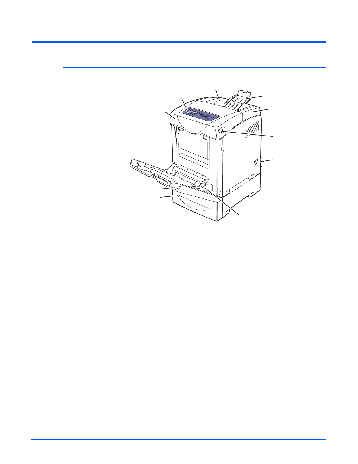
General Information
Parts of the Printer
Front and Side Views
6
5
7
4
3
2
1. Tray 2
2. Tray 3
3. Tray 1 (MPT)
4. Front Cover (Door A)
8
9
10
1
s6180-346
5. Control Panel
6. Output Tray
7. Extender Cover
8. Top Cover
9. Front Cover Release Button
10. Power Switch
1-4 Phaser 6180 Color Laser Printer Service Manual
Page 25

Rear View
General Information
1
2
3
4
s6180-259
1. Ethernet Port
2. Parallel Port
3. USB Port
4. Power Cord Connector
Phaser 6180 Color Laser Printer Service Manual 1-5
Page 26

General Information
Control Panel
The Control Panel consists of 2 LEDs, 1 display window, and 8 functional
buttons. These buttons are used to navigate the menu system, perform
functions, and select modes of operation for the printer.
Control Panel Button Descriptions
3
Ready
CMYK
1 2
4 5 7 8
6
s6180-333
1. Ready LED (Power/Status) LED On - Ready to print or processing print
job.
LED blinking - The printer is receiving data.
LED Off - An error has occurred and the
printer is offline.
2. Error LED Light On - Error with print job.
(blinking = not user fixable)
(On solid = user fixable)
3. Graphic Control Panel Display Displays printer settings, status, and
messages.
4. Menu Button Changes display between Menu mode and
Print mode.
5. 4 Way Cursor Buttons Moves between the Menu levels.
Up and Down arrows Switches between Menus or Items on the
same level.
Right and Left arrows Switches between the Menu levels.
6. Cancel Button Cancels the current print job.
7. OK Button Move to the next level, confirm setting, and
print report.
8. Wake Up LED/Button LED comes On when the printer is in Power
Saver Mode. Press this button to exit the
Power Saver Mode.
1-6 Phaser 6180 Color Laser Printer Service Manual
Page 27

LED Indicators
LED State Printer State
Green Ready to Print or in Power Saver mode
Flashing Green Processing print job
Red Error occurs, can be fixed by user
Flashing Red Error occurs, cannot be fixed by user
Control Panel Shortcuts
Mode Buttons Pressed at Power On
Service Diagnostics Up + Down arrow buttons
General Information
Reset Password to 0000
(used when the Control Panel menus
are locked)
Boot Download for Controller Up + Down + Menu buttons
Menu
Phaser 6180 Color Laser Printer Service Manual 1-7
Page 28

General Information
Printer Options
Additional Memory
Phaser 6180 printer options include:
■ Additional Memory (256 MB/ 512 MB/ 1024 MB)
■ Optional 550-Sheet Feeder (Tray 3)
■ Duplex Unit
■ Multi-Protocol Network Card
The printer features one slot that accepts 256, 512, or 1024 MB of DDR2
DIMMs. Memory modules must meet the following characteristics:
■ 200 Pin DDR2 DIMM (8 chip type)
■ Unbuffered, Non-parity
The printer Configuration page lists the amount of RAM installed in the printer.
Duplex Unit
s6180-447
User can install the Duplex Unit without using any tools and by simply
removing the Transfer Unit.
Duplex Unit
s6180-452
1-8 Phaser 6180 Color Laser Printer Service Manual
Page 29

Multi-Protocol Network Card
Not
The Multi-Protocol Network Card provides additional protocols and security
features including IPP, SMB, SSL/HTTPs, WINS, DDNS, and Netware.
General Information
s6180-449
Optional 550-Sheet Feeder (Tray 3)
The Optional 550-Sheet Feeder increases the input capacity of the printer and
can be attached to the printer underneath Tray 2 with 2 screws.
e
Only one Optional 550-Sheet Feeder is supported.
s6180-448
Phaser 6180 Color Laser Printer Service Manual 1-9
Page 30
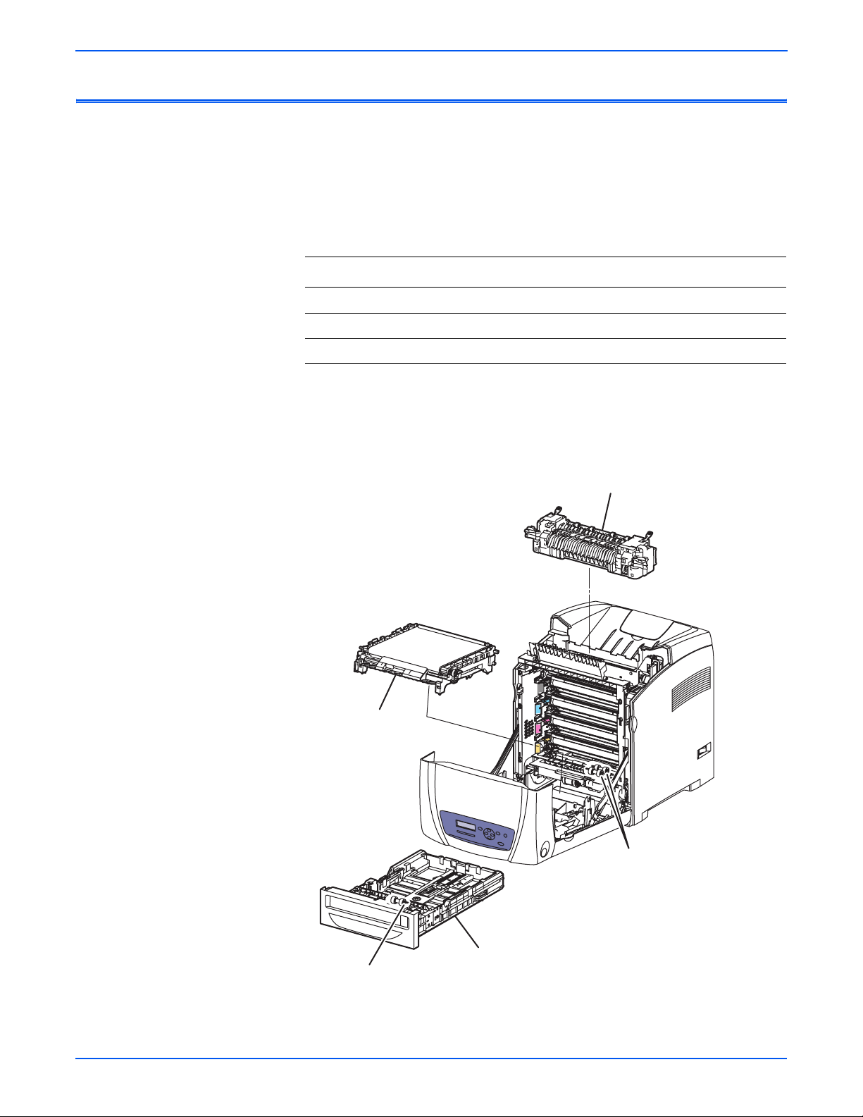
General Information
Not
Maintenance Items
An item is a printer part or assembly that has a limited life, and requires
periodic replacement. Routine maintenance items are typically customer
replaceable.
The listed items have limited life and require periodic replacement.
Phaser 6180 Maintenance Items
Item Print Life
Transfer Unit Up to 100,000 pages
Fuser Up to 100,000 pages
Feed/Retard Roller Up to 100,000 pages
e
Print life is based on “typical” office printing and 5% coverage per color on
24 lb. paper. The 100,000 life is not guaranteed and varied depending on
usage habits.
Transfer Unit
Fuser
Feed Rollers
Tray 2
Retard Roller
1-10 Phaser 6180 Color Laser Printer Service Manual
s6180-451
Page 31
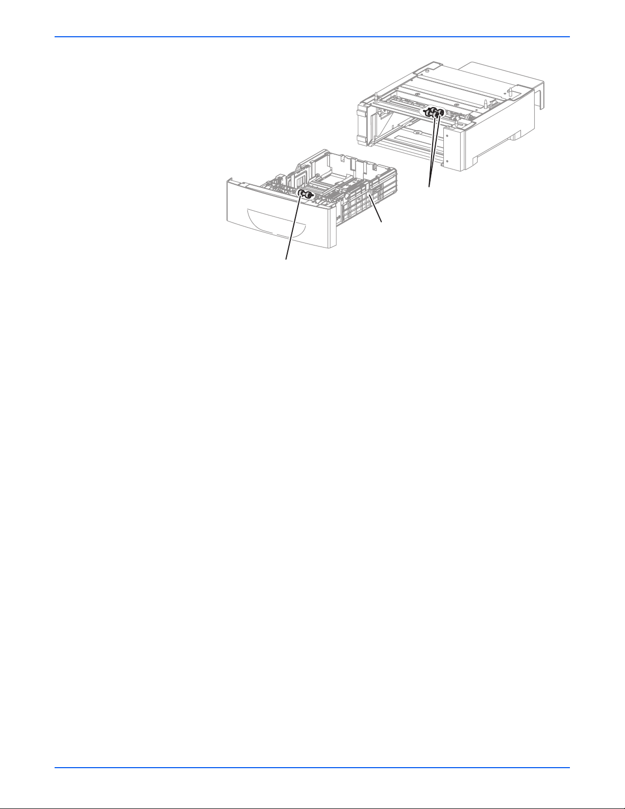
Tray 3
Optional 550-Sheet Feeder
Retard Roller
General Information
Optional 550-Sheet Feeder
Feed Roller
s6180-351
Phaser 6180 Color Laser Printer Service Manual 1-11
Page 32
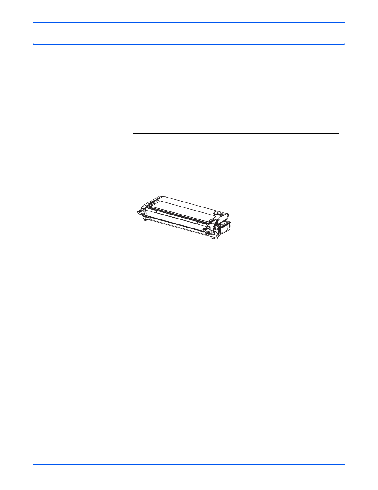
General Information
Consumables
Consumables consist of 4 Print Cartridges used in the printer.
CMY Toner will not be consumed when printing in Mono mode or when
printing a Grayscale job only. Internal counters track Consumables and
Maintenance Items life usage.
Each Print Cartridge has a CRUM (Customer Replaceable Unit Meter) to
record the information. CRUM counts the amount of remaining toner. When
toner empty is detected, Life End status will be sent to indicate toner empty.
Life ratings are based on A-size sheets at 5% coverage.
Print Cartridge Print Life
Color Mono
Standard Capacity 2,000 pages 3,000 pages
High Capacity 6,000 pages 8,000 pages
s6180-352
1-12 Phaser 6180 Color Laser Printer Service Manual
Page 33

Printer Specifications
Functional Specifications
General Information
Characteristic Specification
Printing Technology Recording System: Tandem electro-photographic system
using OPC Drum and direct transfer by the Transport Belt
Exposure System: 4 semiconductors laser beam scanning
system
Transfer System: Four-color finished toner image is
transferred onto the paper
Fusing System: Thermal fusing system by Free Belt Nip
Fusing (FBNF)
Print Volume Average 2,000 PV/month
Maximum 60,000 PV/month
For Duplex prints, prints on the front and back sides of
paper are counted as 2 PV.
Maximum PV is 2,000 PV/day
Color Medium Cyan, Magenta, Yellow, and Black Print Cartridges
Resolution /
Addressability (dpi)
Print-Quality Mode 600 x 600 x 1bit (Standard)
Average Image
Coverage
Maximum Image
Coverage
Printer Life 300,000 pages
Maximum Duty Cycle 60,000 pages/month*
Warm-Up Time Less than 30 seconds from Power On
Operating System Windows 2000/ 2003 Server/ XP Pro/ XP/ Vista
Standard 600 x 600 x 1
Enhanced 600 x 600 x 4
600 x 600 x 4bit (Enhanced)
Color 5% each CMYK
Mono 5%
240% for all C, M, Y, K combined
Macintosh OS 10.2 or higher
Linux Redhat, SuSe, and TurboLinux 10
Desktop
* Assumes a 30 day month of printing.
Phaser 6180 Color Laser Printer Service Manual 1-13
Page 34

General Information
Memory Specifications
Electrical Specifications
Characteristic Specifications
Memory Minimum 128 MB On-Board
memory
Maximum 1152 MB
Supported RAM Supports up to 1152 MB of DDR2 DIMM with one
slot for 256 MB/ 512 MB/1 GB
Characteristic Specification
Power Supply Voltage/Frequency
Line Voltages 110-127 VAC ± 10%
220-240 VAC ± 10%
Frequency Range 50/60 Hz ± 3 Hz
Current Capacity 110 V Engine: < 8 A
220 V Engine: < 4 A
Power Consumption
Power Saver Mode 110 V Engine: 5.4 W
220 V Engine: 6.3 W
Standby Mode (Fuser On) 110 V: 70 W
220 V: 68.9 W
During Color Continuous
Printing
During B/W Continuous
Printing
Maximum Value 900 W
In-rush Current
Maximum at 1st 2.5 msec 50 Amp (Cold start)
Within 10 msec 80 Amp (110 V/ 220 V/ 240 V)
110 V Engine: 450 W
220 V Engine: 410 W
110 V Engine: 410 W
220 V Engine: 375 W
135 Amp (Hot start
85 Amp (100 V)
Leakage Current Power Current
110 V M/C < 3.5 (UL) mA
120 V < 3.5 (UL) mA
220-240 V < 3.5 mA (IEC)
E
NERGY STAR Sleep Mode < 45 W
1-14 Phaser 6180 Color Laser Printer Service Manual
Page 35

Print Speed
General Information
Simplex (ppm) Duplex (ipm)
Resolution
600 Standard 20/20 26/25 14/14 18/18
600 Enhanced 20/20 26/25 14/14 18/18
Paper Type (65 - 220 gsm)
Letter 18 26 12 21
A4 17 25 12 25
A5 18 26 12 21
Legal 15 26 11 18
Transparency 6 6 N/A N/A
Environmental Specifications
Characteristic Specification
Temperature
Operating 5 to 32° C (41 to 90° F)
Color
A/A4
Mono
A/A4
Color
A/A4
Mono
A/A4
Standby -20 to 40° C (-4 to 104° F)
Humidity (% RH)
Operating 15 to 85% RH
Standby 5 to 85% RH
Altitude
Operating 0 to 3,500 meters (11,482 feet)
Acoustic Noise LWA(B) Sound Power Level (B) Sound Pressure (dBA)
Printing 6.6 49.1
Standby 4.0 28.6
Phaser 6180 Color Laser Printer Service Manual 1-15
Page 36

General Information
Operating Mode
Mode Condition Description
Running Mode The printer is under operating condition
such as running or recording.
Fusing The system keeps the operating
temperature.
Exposure The Laser Unit Motor runs at the running
speed.
Recording The system is under operating condition.
Cooling Fan The fan operates at high speed.
Control Panel
Operation
Standby Mode The printer is under standby condition.
Fusing The system keeps the standby temperature.
Exposure The system is at Pause.
Recording The system is at Pause.
Cooling Fan The fan operates at low speed.
Control Panel
Operation
Power Saver
Mode
Fusing The system is Off.
Exposure The system is at Pause.
Recording The system is at Pause.
Cooling Fan The system is Off.
Control Panel
Operation
LCD - Backlight: On
LED - Ready LED is turned On.
LCD - Backlight: On
LED: If printer is online, Ready LED is
turned On.
The printer enters into the Power Saver
mode to reduce power consumption when it
has not received print data for the specified
time.
LCD: Off, LCD Backlight: Off
LED: Power Saver LED is turned On.
Note: When the printer receives a print job or the Wake Up button is pressed, the
printer exits the Power Saver mode and enters the Ready mode.
1-16 Phaser 6180 Color Laser Printer Service Manual
Page 37

First Print Output Time (FPOT)
First Print Output Time is defined as a time from when the engine receives a
Start signal in Ready state, until a single page is printed and delivered to the
output tray.
The following conditions are applied:
■ The Controller does not keep the print engine waiting
■ The printer is at Standby mode (Laser Unit Motor Off, Fuser Ready)
■ Paper is A size Short Edge Feed (SEF)
■ Process control time is not included
Mode FPOT (sec.)
Color As fast as 10.0
Mono As fast as 10.0
General Information
Phaser 6180 Color Laser Printer Service Manual 1-17
Page 38

General Information
Not
Image Specifications
e
The printer has 4 mm margins on all sides.
■ Refer to “Print-Quality Troubleshooting” on page 5-1 for detailed
specifications.
Characteristic Specification
Maximum Print Area 210.9 mm (8.2 inches) x 351.6 mm (13.8 inches)
Guaranteed Print Area 207.9 mm (8.2 inches) x 347.6 mm (13.7 inches)
Skew 190 mm ± 1.2 mm
Perpendicularity 114.5 mm ± 0.8 mm
Parallelism
Horizontal 180 mm ± 1.2 mm
Vertical 234 mm ± 1.2 mm
Linearity
Horizontal 190 mm ± 0.5 mm
Vertical 234 mm ± 0.5 mm
Slant 269 mm ± 1.2 mm
Magnification Error
Horizontal Simplex 234 mm ± 0.5 mm
Horizontal Duplex 234 mm ± 0.8 mm
Vertical Simplex 190 mm ± 0.5 mm
Vertical Duplex 190 mm ± 0.8 mm
Registration
Leading Edge 10.0 mm ± 2.0 mm
Side Edge 8.5 mm ± 2.5 mm
1-18 Phaser 6180 Color Laser Printer Service Manual
Page 39
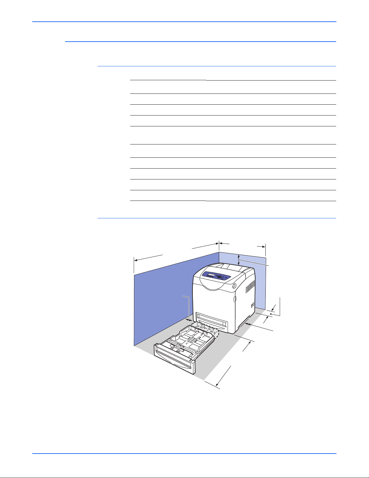
Physical Dimensions and Clearances
Printer Dimensions
Print Engine 6180N 6180DN
Height 470 mm (18.5 in.) 470 mm (18.5 in.)
Width 400 mm (15.7 in.) 400 mm (15.7 in.)
Depth 493 mm (19.4 in.) 493 mm (19.4 in.)
General Information
Weight (base printer with
standard fill print cartridges)
Optional 550-Sheet Feeder Value
Height 138 mm (5.4 in.)
Width 400 mm (15.7 in.)
Depth 493 mm (19.4 in.)
Weight 7.7 kg (16.9 lb.)
Minimum Clearances
121.5 cm
(47.8 in.)
10 cm
(4 in.)
27.2 kg (59.8 lb.) 28.3 kg (62.3 lb.)
60 cm
(23.6 in.)
35 cm
(14 in.)
13 cm
(5 in.)
10 cm
(4 in.)
60 cm
(23.6 in.)
s6180-261
Phaser 6180 Color Laser Printer Service Manual 1-19
Page 40

General Information
Mounting Surface Specifications
These specifications apply to any printer used as a table-top printer.
1. In order to function properly, the printer must be placed on a surface with
the following minimum dimensions.
121.5 cm
10 cm
60 cm60 cm
13 cm
10 cm
s6180-264
2. Mounting surface flatness must be within the specified range.
Right Hand Side
5mm Max
s6180-263
1-20 Phaser 6180 Color Laser Printer Service Manual
Page 41
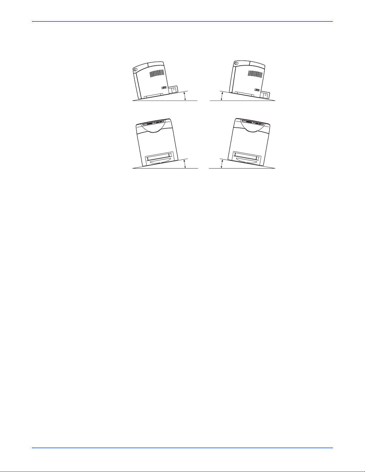
3. The printer must not be tipped or tilted more than 7 mm.
10° or 7 mm
General Information
10° or 7 mm
s6180-262
Failure to adhere to the specified mounting specifications will void all
guarantees of print-quality and/or performance. Known problems that can
occur as a result of exceeding the mounting surface specifications are:
■ Color-to-Color mis-registration, primarily in the horizontal (laser scan)
direction.
■ A smear or line of toner approximately 40 mm from the training edge of
the print.
Phaser 6180 Color Laser Printer Service Manual 1-21
Page 42

General Information
Media and Tray Specifications
The following tables list the recommended Xerox paper for the printer.
Supported Paper Size
Paper Type Dimension Tray 1 (MPT) Tray 2, 3
Letter 8.5 x 11 in. Yes Yes
Legal 8.5 x 14 in. Yes Yes
US Folio 8.5 x 13 in. Yes Yes
Executive 7.25 x 10.5 in. Yes Yes
A4 210 x 297 mm Yes Yes
A5 148 x 210 mm Yes Yes
B5 JIS 182 x 257 mm Yes Yes
Custom Size* Yes Yes
* All trays support Custom sizes. Tray 1 supports a wider range of Custom size
dimensions than trays 2 and 3.
Supported Paper Types and Weights
Paper Type Paper Weight Tray 1 (MPT) Tray 2, 3
Plain Paper 65-90 g/m
Letter Head 85-120 g/m
Glossy Paper 100-163 g/m
Thick Glossy Paper 164-216 g/m
Pre-Punched 65-90 g/m
Thin Card Stock 100-163 g/m
Thick Card Stock 170-216 g/m
2
2
(22-32 lb. Bond) Yes Yes
2
2
2
(17-24 lb. Bond) Yes Yes
2
2
Yes Yes
Yes Yes
Yes Yes
Yes Yes
Yes No
Label N/A Yes Yes
Transparency N/A Yes No
Special 100-163 g/m
2
Yes No
(30-60 lb. Cover)
Supported Envelopes
Type Dimension Tray 1 (MPT) Tray 2, 3
Envelope #10 4.12 x 9.5 in. Yes No
Monarch Envelope 3.87 x 7.5 in. Yes No
C5 Envelope 162 x 229 mm Yes No
DL Envelope 110 x 220 mm Yes No
Note: Do not use envelopes with hot melt glue, windows, or metal clasps.
1-22 Phaser 6180 Color Laser Printer Service Manual
Page 43

Controller Functions
Job Control
Cancel Print
Forced Output
IP Filter
General Information
User can cancel a print job while printing is in progress using the Cancel
button on the Control Panel. Job cancellation is not immediate. Depending on
the job size, it may take a while to completely cancel.
This function forces the printer to print the received data when the printer is
waiting for the remaining data during job processing.
User can accept or reject print jobs up to five specified IP addresses. IP filter
is available only to LPD and Port9100.
Job Recovery
When a print job fails due to a paper jam, the printer automatically restarts the
job after the jammed paper is removed. User does not have to reprint the
entire job.
Job Timeout
When job transmission is interrupted for a certain period of time, the print data
is deleted as an error. Timeout setting can be changed using the menu on the
printer’s Control Panel.
Print Volume Management
Print Volume (PV) Management manages print volume per user and can
manage up to 50 users.
Phaser 6180 Color Laser Printer Service Manual 1-23
Page 44

General Information
RAM Disk
RAM Disk functions when memory is expanded, enabling Collation, Secure
Print, Proof Print, Form Overlay, and Font Download. 256 MB is needed to
enable RAM Disk and all related functions.
Collation
The job is stored in the memory and multiple copies are printed. When the
entire job does not fit in the memory, the printer prints one copy up to the
stored pages, and the remaining are discarded.
An error message will appear on the Control Panel: “Error xxxx Press set key.”
Two options are available to ensure Job Collation will process effectively:
■ Break large print job into multiple small print jobs
■ Increase memory for the printer
Secure Print
When memory is expanded to 256 MB or more, the printer holds print data,
including a User Password (11 digits), User Name, and Document Name in
the memory.
■ User ID – consists of a variable length from 1 to 24 byte characters (20H-
FFH). The driver requests the User ID from the user when the Secure
Print option is selected. A user ID cannot be blanked with only space
characters.
■ User Password – consists of a variable length from 0 to 11 digits. The
password is an optional input and hidden from the user interface by
displaying “*” for each digit. If a password is not specified, the driver will
accept it as a zero-length string so that a password will not be required
when requesting job output from the printer.
■ Document Name – consists of a variable length from 0 to 24 characters
(20H-FFH) that specifies the document name.
The data will not be printed until the same password, user name, and
document name are provided via the printer menu on the Control Panel. User
can remove or keep the data after printing the document. The data remains in
the printer memory as long as it is not cleared and will be cleared when the
printer is turned off. User can omit entering a password (this is called Store
Print - not available for MAC OS 10.2.).
Proof Print
Proof Print can be selected only when multiple sets of prints are specified in
the printer driver. Proof Print requires at least 256 MB of memory. The printer
prints only the first set of the print data including a user name and document
name specified in the printer driver. User can keep or remove the data using
the printer menu on the Control Panel. The data remains in the printer
memory as long as it is not cleared and will be cleared when the printer is
turned Off. This function is not available for MAC OS 10.2 and Linux operating
systems.
1-24 Phaser 6180 Color Laser Printer Service Manual
Page 45

Form Overlay
Not
The function for writing PCL6 forms are downloaded into RAM Disk.
Font Download
PCL6 fonts can be downloaded into RAM Disk.
Billing Meters
The Billing Print counter provides the number of pages printed properly
(simplex print is counted as 1 and duplex print is counted as 2 - including N
up).
If an error has occurred after the one side printed properly during duplex
printing, it is counted as 1.
General Information
e
Same data is stored in two or more addresses in one IC. When the
Controller is replaced, IC can be transferred.
ID Print
Counter Description
Color Print Counter Counts the number of pages printed in color (7 digits).
Mono Print Counter Counts the number of pages printed in mono (7 digits).
Total Print Counter Count the total number of pages printed in color and
mono (7 digits).
User can position and print the User Name on the upper right, upper left,
lower right, and lower left (only for PCL6) of the page.
Non-Genuine Mode
When the Print Cartridge life has ended, the printer stops accepting print
request (life of the Print Cartridge is counted by the counter in the CRUM).
This mode can be changed so the printer will not stop at the end of the print
cartridge rated life; however, the printer will display an end of life message on
the Control Panel.
Print Cartridge Control Panel Display
Print Cartridge Control Panel Display Functionality
Life
Warning
Normal Status
Xerox Xerox (TM)
Print Cartridge
Phaser 6180 Color Laser Printer Service Manual 1-25
Error
Replace
Soon
End of
Life Error
Replace
Print
Cartridge
Prints with full
functionality.
Page 46

General Information
Not
Print Cartridge Control Panel Display (continued)
Print Cartridge Control Panel Display Functionality
Life
Normal Status
Warning
Error
End of
Life Error
Xerox (refill
Print
Cartridge)
Other OEM
(non-Xerox
printer
manufacturer)
Non-Xerox
Print Cartridge
Manufacturer
Toner Remaining Amount
The CentreWare Internet Services (IS) and PrintingScout (SimpleMonitor)
allow the printer to display toner remaining amount.
Maintenance Function
Firmware Update
Xerox (TM)
Print Cartridge
Non-Xerox Print
Cartridge
Non-Xerox Print
Cartridge
Replace
Soon
No Life
Tracking
Empty Prints with full
functionality up to 40%
of the Print Cartridge
life.
Printer displays error
and will not print.
Replace
Print
Cartridge
Prints with full
functionality.
The Image Processor Board and Multi-Protocol Network Card firmware can
be updated by customers and service technicians using Windows PC or
Macintosh with dedicated utilities. Firmware updates are available at
www.xerox.com/office/6180support.
Detailed procedures are available in the “” on page A-2.
e
Boot Code can be updated via USB or Parallel port only.
Updated Firmware Windows
Via USB/IEEE1284 Via Network (port 9100)
Image Processor Board Available Available
Multi Protocol Network Card Available Available
MCU Board Available Available
* MCU Board cannot be updated when ROM starts to be used for MCU Board.
1-26 Phaser 6180 Color Laser Printer Service Manual
Page 47

Diagnostics
Information Pages
Demo Page
Configuration Page
General Information
Two types of diagnostic functions are available:
1. Auto Diagnostics: The printer is checked when it is turned on. It is
checked whether hardware (ROM, RAM, ASIC, etc...) operates properly.
2. Manual Diagnostics: Only qualified service personnel can perform manual
diagnostics using the Service Mode in the Control Panel.
Demo Page provides sample of print for the Phaser 6180 Color Laser Printer.
The Demo Page is printed in color from selected paper tray.
s6180-504
Phaser 6180 Color Laser Printer Service Manual 1-27
Page 48

General Information
User can print the Configuration Page from the Control Panel > Menu >
Information Pages > Configuration. The Configuration Page is printed in
from the default tray and includes the following information.
Configuration Page Information
General Description Detail Description
Title Prints Title of the document
Product Name (Logo) Prints organization’s logo
General Total Impressions, Total Color Impressions, Total
Black Impressions, Memory Capacity, Printer
Language, Number of Fonts Available, PostScript
Version, PostScript Serial Number, Firmware
Version, Boot Version, Engine Version, PostScript
CRD Version, Default Paper, Default Language,
Current Temperature, Current Humidity
Printer Options Multi-Protocol Card (when installed)
Duplex Unit: (00.00.00)
Paper Tray: Tray 1 (MPT), Tray 2-3
Print Volume Print Volume for each paper size
Network Setup Firmware Version, MAC Address, Ethernet, TCP/IP,
Parallel Setup ECP, Adobe Protocol
USB Setup Adobe Protocol
System Setup PowerSaver Time, Audio Tones, Time-Out,
Maintenance Auto Reg Adj, Non-Xerox Toner
PCL Paper Tray, Paper Size, Orientation, 2-Sided, Font,
PostScript PS Error Report, PS Job Time-Out, Paper Select
Control Panel Panel Lock
Tray Settings MPT Mode, Tray 2
PCL Fonts List
Protocol, Host Access List, Adobe Protocol
Language, Auto Log Print, Print ID, Print Text,
Banner Sheet, RAM Disk, Tray Switching, mm/inch,
Start Up Page
Symbol Set, Font Size, Font Pitch, Form Line,
Quantity, Image Enhance, Hex Dump, Draft Mode,
LineTermination, Default Color
Mode
User can print the PCL Fonts List default in color on A size paper from default
tray. The PCL Font List contains:
■ No., Fonts, Escape Sequence, Font ID, Sample
PCL Macro List
User can print the PCL Macro List default on A paper size from default tray.
1-28 Phaser 6180 Color Laser Printer Service Manual
Page 49

PostScript Fonts List
User can print the PostScript Fonts List default on A size paper from default
tray. The PostScript Fonts List contains:
■ Print Fonts, Fonts Sample
Job History Report
The printer can retain up to 20 job logs. Job History can be manually or
automatically printed when the number of the retained job logs has reached
20. User can print the Job History Report default on A paper size from default
tray. The Job History Report contains:
■ Job sent data and time
■ Input Interface (USB, LPD,...etc.)
■ Document Name (File Name)
■ Output Color
■ User Name/Host Name
General Information
■ Number of Printed Pages (Color/Mono)
■ Number of Printed Impressions (Color/Mono)
■ Paper Size
■ Result (successful, error,...etc.)
Phaser 6180 Color Laser Printer Service Manual 1-29
Page 50

General Information
Error History Report
The printer can retain up to 42 jam errors and up to 42 fatal errors. User can
print the Error History Report default on A paper size from default tray using
the printer menu in the Control Panel.
Jam Error log includes the following information:
■ Item No., Total Print Count, Paper Jam Type
Fatal Error log includes the following information:
■ Item No., Total Print Count, Chain-Link Code
Print Meter (Print Volume Report)
User can print the Print Meter page default on A paper size from default tray.
The Print Meter page contains:
■ Date of Initialization, Job Accounting User Name, Pages, Sheets, Date/
Time
s6180 506
1-30 Phaser 6180 Color Laser Printer Service Manual
Page 51

Theory of Operation
In this chapter...
■ Phaser 6180 Printer Operational Overview
■ Printing Process
■ Paper Path of the Printer
■ Major Assemblies and Functions
■ Printer Modes
■ Printer Control
■ Drive Transmission
Chapter
2
Page 52
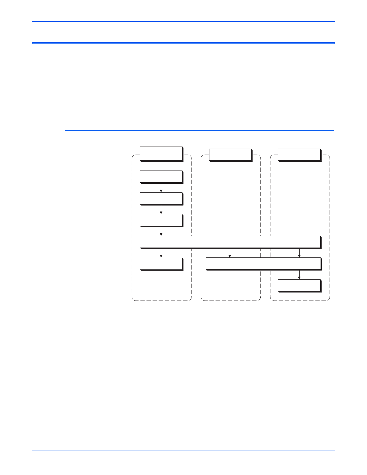
Theory of Operation
Phaser 6180 Printer Operational Overview
The Phaser 6180 Color Laser Printer is a full-color laser printer that uses
Raster Output Scanner (ROS) lasers with an electrophotographic four-color
CMYK process. The tandem system consists of four color print cartridges (C,
M, Y, and K) which creates the toner image.
The following block diagram provides the sequence of events for the
xerographic process (dashed lines) and the paper flow (solid lines) into and
out of the Phaser 6180 Printer.
Print Process Block Diagram
Print Cartridge
(C, M, Y, K)
(1) Charge
(2) Exposure
(3) Development
(5) Cleaning
Transfer Unit
(4) Transfer (Drum to Paper)
(6) Neutralization
Paper
(7) Fusing
s6180-133
2-2 Phaser 6180 Color Laser Printer Service Manual
Page 53

Printing Process
Theory of Operation
The Phaser 6180 Printer print process consists of the following steps:
1. Charging – The Drum surfaces are charged with electricity.
2. Exposure – The Drums are exposed to laser beams.
3. Development – Image is developed with toner.
4. Transfer (Drum ---> Paper) – Four color finished toner image on the
Drums is transferred onto the paper.
5. Cleaning (Print Cartridge) – Remaining toner on the drums is collected.
6. Neutralization – The Detack Saw neutralizes the charge on the paper via
the Belt.
7. Fusing – The Fuser applies toner on to paper using heat and pressure.
8. Cleaning – Remaining toner on the Transfer Unit is collected.
Print Cartridge (C, M, Y, K)
(1) Charging
(3) Development
(4) Transfer
(5) Cleaning
Laser Unit
(2) Exposure
Fuser
(7) Fusing
Laser Beam
Paper Transfer
Transfer Unit
(4) Transfer
(6) Neutralization
(8) Cleaning
s6180-134
Phaser 6180 Color Laser Printer Service Manual 2-3
Page 54

Theory of Operation
Charging
The Drum surface is charged with negative electricity by discharging of the
Bias Charge Roll (BCR) while rotating at a constant speed. This process is
performed in parallel for Cyan, Magenta, Yellow, and Black colors.
The BCR is kept in contact with the Drum and rotates following the rotations of
the Drum. The BCR is a conductive roll, which receives negative voltage from
the High-Voltage Power Supply (HVPS) and discharges a negative Direct
Current (DC) voltage.
The Drum surface is uniformly and negatively charged with DC bias voltage.
The Drum surface is a photoreceptor (which is an insulator in a dark area and
a conductor when receiving light) and the Drum inside is composed of
conductor.
The BCR Cleaner contacts with the BCR to catch the toner.
Photoreceptor
HVPS
Cleaning Roll
BCR
Conductor
Drum
s6180-135
2-4 Phaser 6180 Color Laser Printer Service Manual
Page 55
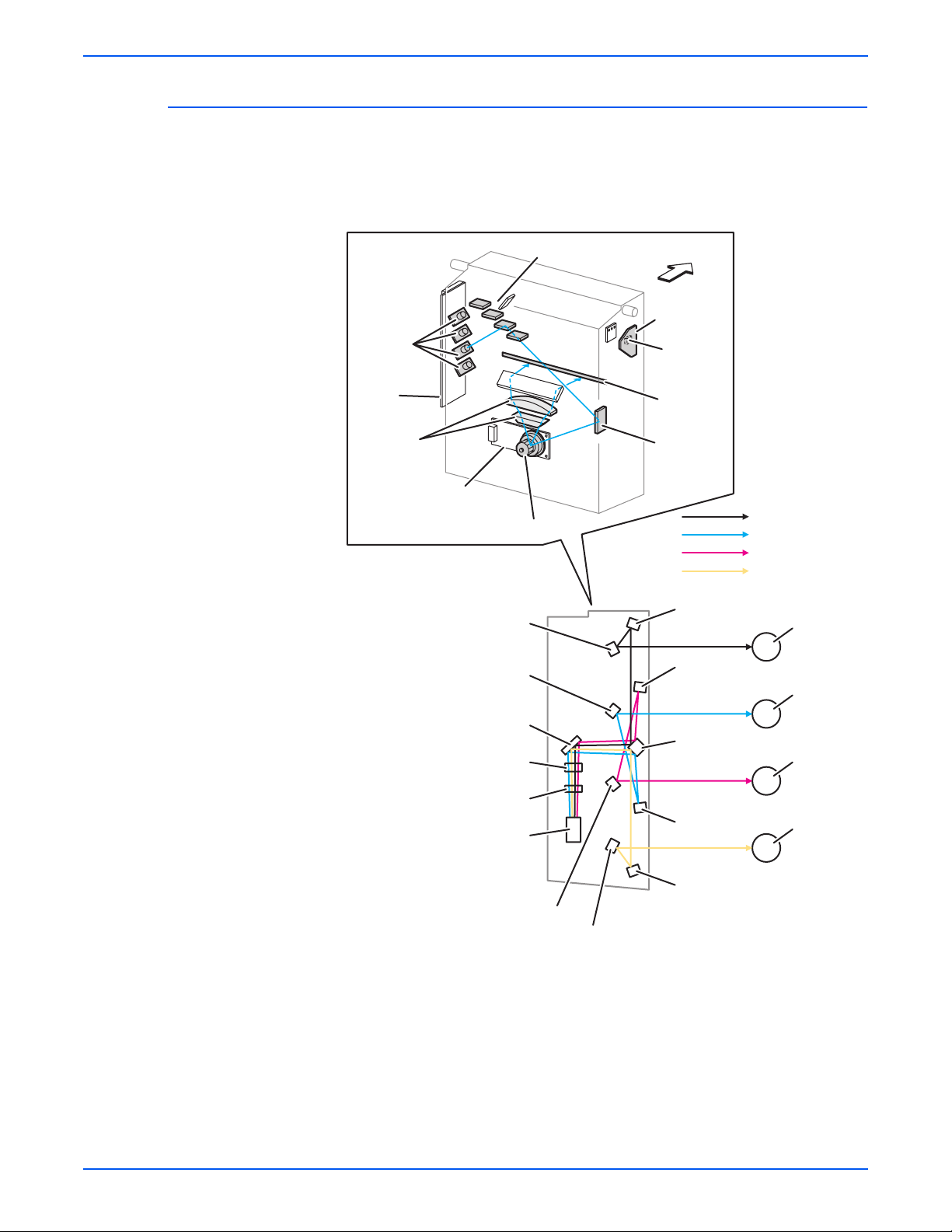
Exposure
Theory of Operation
Laser beams are emitted from the laser diodes in the Laser Unit. The Drum
for each color is scanned from end to end in the axial direction as the polygon
mirror rotates, which attaches the fixed mirror and lenses to the Scanner
Motor of the Laser Unit.
Rear View
Laser
Diodes
Laser
Diode
Board
Lens
Scanner
Mirror
Polygon Mirror
Mirror
Mirror
Front
SOS Board
SOS
Sensor
Window
Mirror
Laser Beam (K)
Laser Beam (C)
Laser Beam (M)
Laser Beam (Y)
Mirror
Drum (K)
Mirror
Drum (C)
Mirror
Lens
Lens
Polygon
Mirror
Mirror
Mirror
Mirror
Mirror
Mirror
Drum (M)
Drum (Y)
s6180-136
Phaser 6180 Color Laser Printer Service Manual 2-5
Page 56

Theory of Operation
The negative charged Drum surface is scanned by the laser beams to form an
invisible electrostatic latent image on the drum surface. The process is
performed in parallel for Cyan, Magenta, Yellow, and Black colors.
The area on the surface where the voltage potential drops due to exposure to
the laser beam becomes the electrostatic latent image.
Laser Unit
Laser Beams
Concept of Drum
Photoreceptor
Conductor
Laser Beam
Negative Electric Charge
Positive Electric Charge
Photoreceptor
Conductor
Drum
Electrostatic
Latent Image
Drum Surface
Potential on
Drum Surface
Laser Beam
-V
0
Laser Beam
Electrostatic
Latent Image
s6180-137
2-6 Phaser 6180 Color Laser Printer Service Manual
Page 57

Development
Theory of Operation
Toner is electrically attached to the invisible electrostatic latent image on the
drum surface to form the visible toner image on the Drum.
The toner in the Print Cartridge is agitated by the built-in Agitator and fed into
the Developer part. The Augers are driven by the Toner Motor and the
Developer Motor in the Main Drive. The toner to be consumed according to
the print count is calculated and fed into the Developer. This process is called
Toner Dispensation, which is controlled by two processes: Pixel Count
Dispense Control (PCDC) and Automatic Density Control (ADC).
The toner fed into the Developer and the carrier in the Developer are agitated
by the Auger, and supplied to the Magnet Roll arranged in the drum surface
area. The toner and carrier are charged by friction due to agitation (toner in
negative, carrier in positive), and they are absorbed electrically. A uniform
layer is formed by the Trimmer Bar as the carrier magnetic substance is
attracted to the Magnetic Roll.
Negative Electric Charge
Positive Electric Charge
Toner
Carrier
Print Cartridge
Agitator
Trimmer Bar
Auger
Developer
Waste Toner Collecting Area
Drum
Magnet Roll
HVPS
s6180-138
Phaser 6180 Color Laser Printer Service Manual 2-7
Page 58

Theory of Operation
The Magnet Roll is covered by a thin semi-conductive sleeve over the surface.
The Developer Bias voltage is supplied to this semiconductor sleeve from the
High-Voltage Power Supply (HVPS). Developer Bias is negative Direct
Current (DC) voltage combined with Alternating Current (AC) voltage. The
Magnet Roll is kept at constant negative voltage against the photoreceptor
layer of the drum by DC voltage. Therefore, at the area on the drum surface
where the negative electric charge does not decrease, potential is lower than
the magnet roll, while the potential is higher than the magnet roll at the area
where the negative charge on the drum surface decreases. The AC voltage
shakes the Developer on the Magnet Roll surface, causing the toner to
transfer to the drum.
Thus, the negatively charged toner is attracted only by the area where the
negative charge has decreased on the drum surface from the Magnet Roll
(electrostatic latent image) and the toner image is formed on the drum. When
the toner is attached, the negative charge at the portion of the drum increases
where the toner is located increases, the potential decreases, and the force to
attract the toner decreases.
Drum Surface
Toner
Image
Electric Potential
on Drum
-V
Developing
Bias
0
s6180-446
2-8 Phaser 6180 Color Laser Printer Service Manual
Page 59
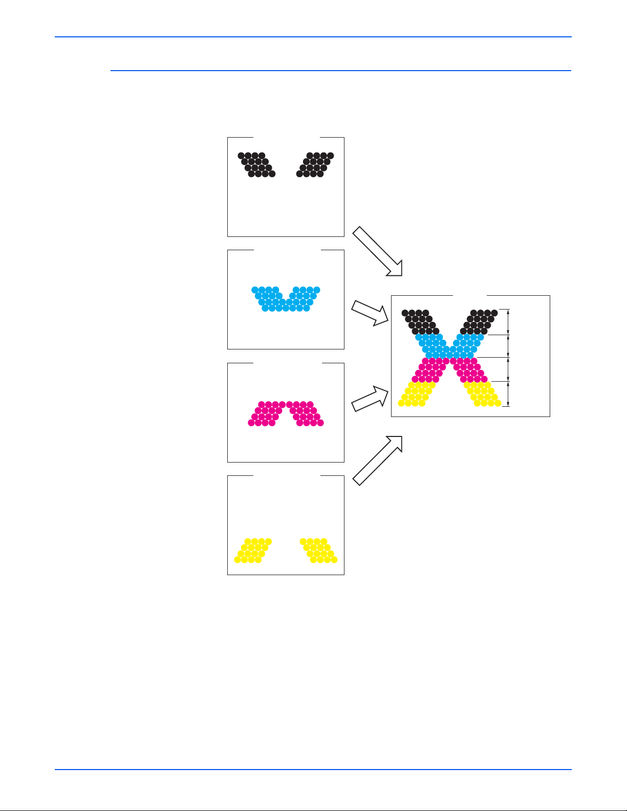
Transfer (Drum ---> Paper)
Toner image formed on the Drum surface is transferred onto the surface of the
paper. The toner is transferred onto the paper in the order of Y, M, C, and K.
(Black Toner Image)
(Cyan Toner Image)
(Magenta Toner Image)
Drum Surface
Drum Surface
Drum Surface
Theory of Operation
Paper
Black
Toner Image
Cyan
Toner Image
Magenta
Toner Image
Yellow
Toner Image
Drum Surface
(Yellow Toner Image)
s6180-140
Phaser 6180 Color Laser Printer Service Manual 2-9
Page 60

Theory of Operation
■ Bias Transfer Roll (BTR) – The BTR is a conductive roll, which receives
positive voltage from the HVPS. The BTR contacts the rear side of the
Belt and applies the positive voltage to the Belt.
■ Transfer Unit (Belt) – The Transfer Unit is a conductive unit, which
receives positive voltage from the BTR. After the negative charged toner
image on the Drum surface is drawn by the positive charge on the belt, it
is transferred from the Drum to the paper. The Transfer Unit feeds the
paper toward the direction of the Fuser.
■ Electric Static Attachment (ESA) Roll – The ESA Roll is a conductive
roll, which receives positive voltage from the HVPS and discharges to the
paper to improve the toner transfer efficiency.
Drum Surface
Paper
Drum (K)
Drum (C)
Drum (M)
Negative Electric Charge
Postive Electric Charge
Ton er
BTR
BTR
BTR
BTR
Drum (Y)
HVPS HVPS
ESA Roll
Transfer Unit
s6180-139
2-10 Phaser 6180 Color Laser Printer Service Manual
Page 61

Cleaning (Print Cartridge)
Excess toner is removed from the Drum and the BCR surfaces, while excess
charge is also eliminated from the drum surface.
■ Drum Cleaning – The cleaning blade contacts the surface of the drum
collecting the excess toner by scraping off toner.
■ Cleaning Roll – The Cleaning Roll contacts the surface of the BCR
collecting the excess toner by scraping off toner.
■ Charge Cleaning – When the Drum is charged by the BCR, any excess
charge hinders the Drum surface from being uniformly charged, which
may lead to print quality problems. The excess charge on the surface of
the Drum is eliminated by irradiating the light of the Erase Lamp (LED).
Theory of Operation
Positive Electric Charge
Negative Electric Charge
Toner
Cleaning Roll
Erase Lamp (LED)
Blade
Conductor
Drum
Photoreceptor
BCR
s6180-141
Phaser 6180 Color Laser Printer Service Manual 2-11
Page 62
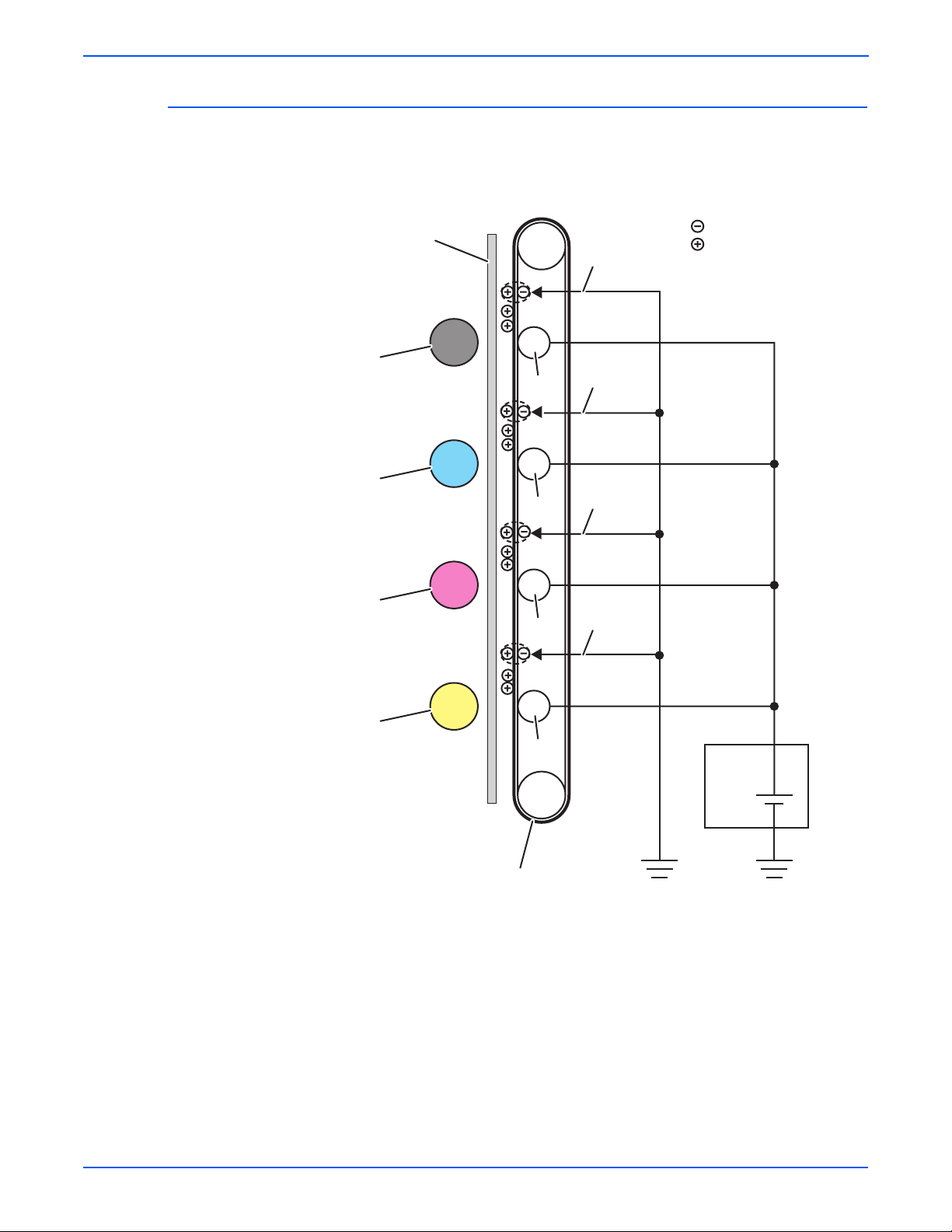
Theory of Operation
Neutralization
The Detack Saw neutralizes the charge on the paper via the Belt.
The Detack Saw, a metal sheet secured at the ground level, is installed at
several millimeters away from the back side of the belt.
Drum
Drum
Drum
Paper
K
C
M
BTR
BTR
BTR
Negative Electric Charge
Positive Electric Charge
Detack Saw
Detack Saw
Detack Saw
Detack Saw
Drum
Y
BTR
Transfer Unit
HVPS
s6180-142
2-12 Phaser 6180 Color Laser Printer Service Manual
Page 63

Fusing
Theory of Operation
Toner is applied by the BTR and the Developers. The toner image is applied
on the paper with the Fuser (Fusing Unit) by the Free Belt Nip Fusing (FBNF)
thermal fusing system. The Heat Roll with the Heater Lamp melts the toner
particles. Toner is fused onto the paper by the combination of heat and
pressure.
Warm-Up Stand By Printing
Main Heater Lamp On On/Off On
Paper
Nip Spring
Nip Head
Cleaning
Fixed Toner
Heat Roll
Heater Lamp
Unfixed Toner
Sheet
Pad
Belt
Belt Frame
s6180-143
A cleaning blade in the Print Cartridge scrapes off toner remaining on the
drum surface after transfer has occurred. Then, the latent charge pattern
remaining on the photoconductive drum is neutralized by the Erase Lamp to
prepare the drum for the next Exposure cycle.
Phaser 6180 Color Laser Printer Service Manual 2-13
Page 64
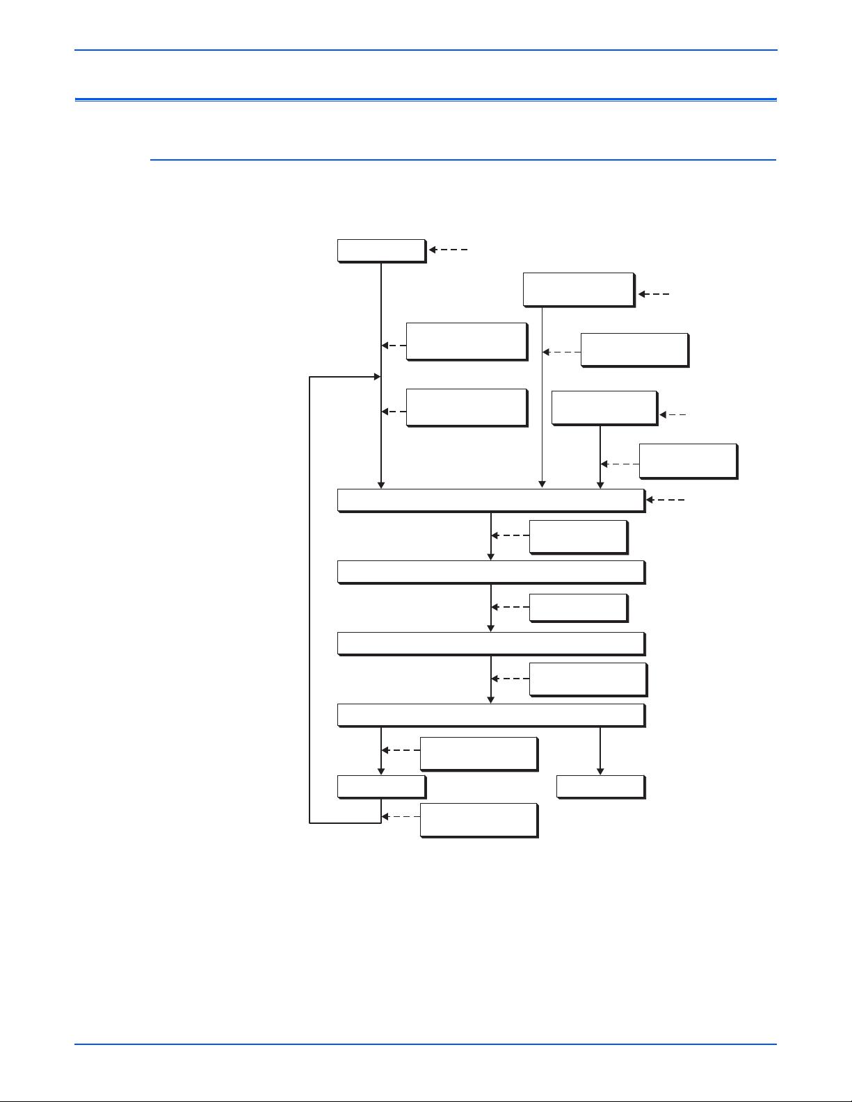
Theory of Operation
Paper Path of the Printer
Paper Path Route
The paper is supplied from Tray 1, 2, or optional Tray 3, and is transported into
the printer along the paper path as shown in the diagram.
Tray 1 (MPT)
Multiple Sheet Feed
Prevention
Motor Drive/Solenoid/
MPT Roll
Turn Roll
Registration
Transfer Unit
Fuser
550-Sheet Feeder
(Tray 3)
Motor Drive/Clutch/
Feed Roll/Turn Roll
250-Sheet Standard
Tray (Tray 2)
Motor Drive/
Clutch/Regi Roll
Motor Drive/Belt
Multiple
Sheet Feed
Prevention
Multiple
Sheet Feed
Prevention
Motor Drive/
Clutch/Feed Roll
Lead Edge
Registration
Motor Drive/Heat Roll/
Pressure Belt
Exit Roll in the Fuser
Motor Drive/Clutch/
Exit Roll
Duplex Module
Motor Drive/Clutch/
Dup Roll
Output Tray
s6180-144
2-14 Phaser 6180 Color Laser Printer Service Manual
Page 65

Paper Path Components
Paper path components for the printer and the Optional 550-Sheet Feeder are
shown in the following figure.
Heat Roller (Fuser)
Regi Roller (Metal)
(Registration)
No Paper Sensor
(250-Sheet
Feeder)
No Paper Sensor
(550-Sheet
Feeder)
Exit Roller (Fuser)
Duplex Gate (Fuser)
Theory of Operation
Laser Beam
Paper Transfer
Paper Sensors
Exit Sensor (Fuser)
Pressure Belt (Fuser)
Duplex Gate
Duplex Roller
(Duplex Module)
Duplex Jam Sensor
(Duplex Module)
Belt (Transfer Unit)
Duplex Roller
(Duplex Module)
Regi Roller (Rubber)
(Registration)
Regi Sensor
(Registration)
Tray 1 (MPT)
No Paper Sensor
Tray 1 (MPT) Roller
Tray 1 (MPT)
Turn Roller
Feed Roller (250-Sheet
Feeder)
Tray 2 Retard Roller
(250-Sheet Feeder)
Turn Roller (550-Sheet Feeder)
Tray 3 Retard Roller (550-Sheet Feeder)
Feed Roller (550-Sheet Feeder)
s6180-145
Phaser 6180 Color Laser Printer Service Manual 2-15
Page 66
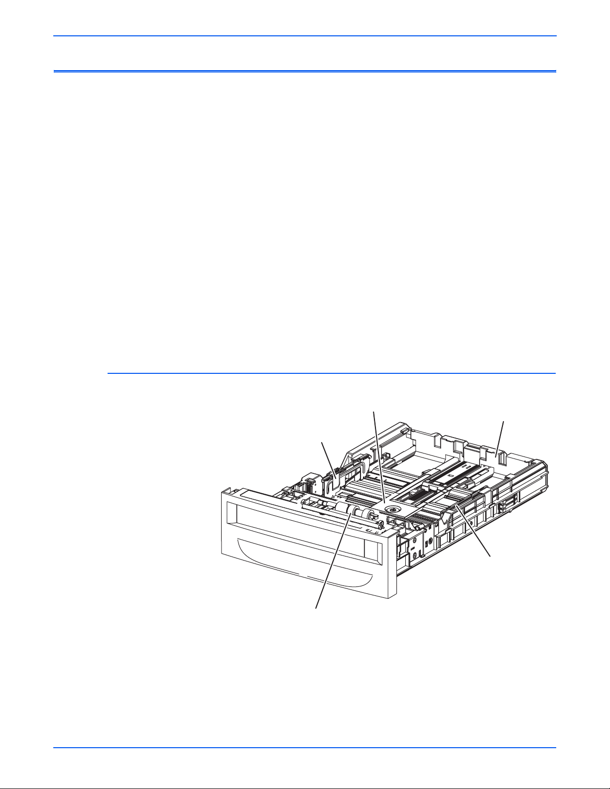
Theory of Operation
Major Assemblies and Functions
Major functional components for the printer are classified into the following
categories based on the printer configuration.
■ Tray 2
■ Paper Feeder
■ Tray 1 (MPT) & Registration
■ Fuser
■ Transfer Unit
■ Laser Unit
■ Print Cartridge
■ Main Drive
■ Refer to “Mechanical Components” on page 2-56 for detailed diagrams.
■ Duplex Unit
Tray 2
■ Tray 3 - Optional 550-Sheet Feeder
Bottom Plate
Left Side Guide
Retard Roll
Tray 2 End Guide
Right Side Guide
s6180-146
■ Tray 2 Left/Right Side Guide
The Side Guide moves at a right angle toward the paper transfer direction
to align the paper width.
2-16 Phaser 6180 Color Laser Printer Service Manual
Page 67
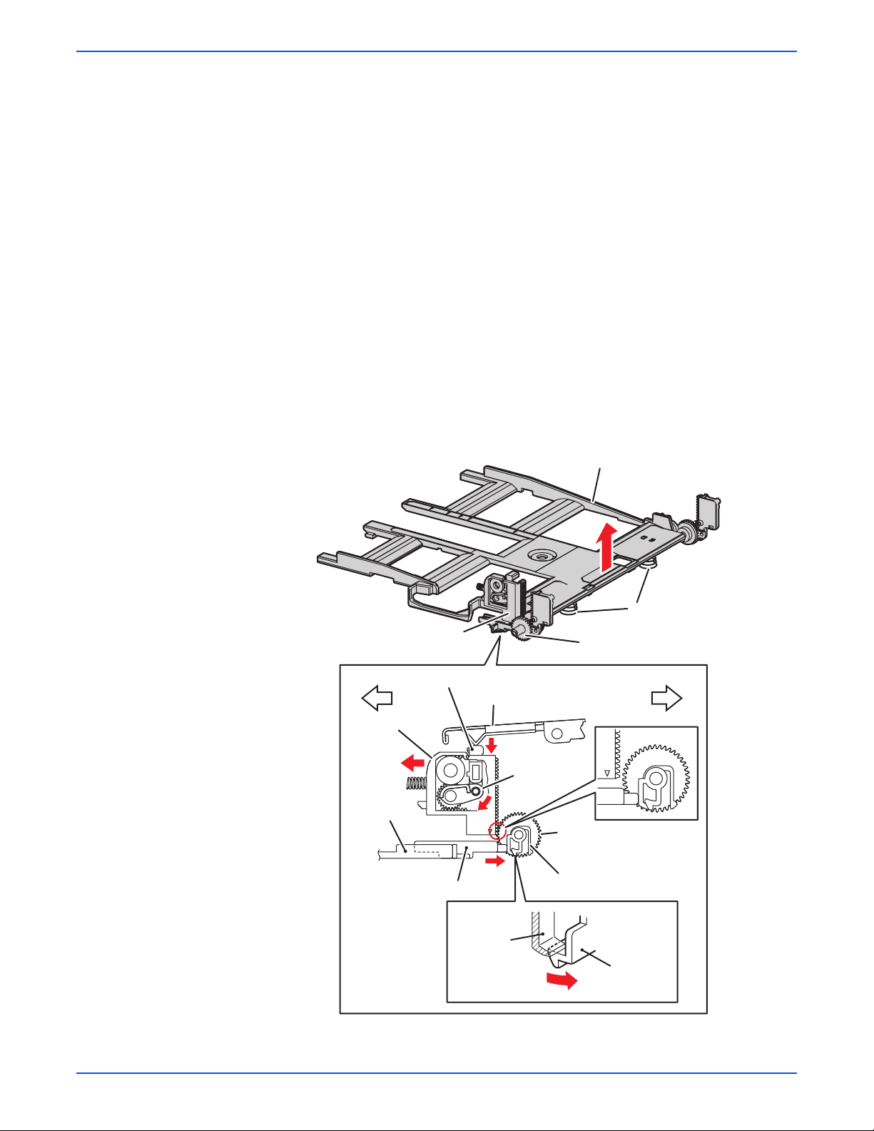
Theory of Operation
■ Tray 2 Retard Roll
The Retard Roll and Feed Roll pinch the paper to prevent multiple sheets
of paper from feeding.
■ Tray 2 End Guide
The End Guide moves in toward the paper transfer direction to determine
the paper size. The On/Off of the Size Switch adjusts according to the
Tray End Guide position to detect the paper size.
■ Tray 2 Bottom Plate
a. When the tray is inserted into the Sheet Feeder, the Actuator is
pushed toward the front by the Left Guide, which pushes the Stopper.
b. The Stopper unlocks the Bottom Lock Oneway Gear.
c. When the tray is pushed until it stops, the Bottom Lock Lever is
pressed down by the Support Nudger in the Sheet Feeder.
d. The Bottom Lock Lever actuates the Bottom Lock Lever Gear, which
pushes the Bottom Rack Lock toward the rear.
e. The gear on the Bottom Rack Lock is disengaged from the Bottom
Lock Oneway Gear, which allows the Bottom Plate to raise up by the
Bottom Up Springs.
Bottom Rack Lock
Bottom Lock Lever
Bottom Rack Lock
e
Left Guide
Actuator
Support Nudger
c
Bottom Lock
Lever Gear
d
a
Bottom Plate
Bottom Up Spring
Bottom Lock Oneway Gear
Front of TrayRear of Tray
Bottom Lock
Oneway Gear
Stopper
Lock Part
(Tray Housing)
Stopper
b
s6180-367
Phaser 6180 Color Laser Printer Service Manual 2-17
Page 68

Theory of Operation
Tray 2 Multiple Sheet Feed Prevention
The sheets loaded into Tray 2 are occasionally stuck together along the
edges, which can cause a multiple feed or a jam. The Nudger Roller feeds the
sheets to a position between the Feed Roller and the Retard Roller. Normally,
when only one sheet is fed, both the Feed Roller and Retard Roller rotate to
allow the sheet to pass.
Feed Roller (Takeaway Roller)
Friction Clutch
Feed Roller (Nudger Roller)
Retard Roller (Separator)
Retard Roller (Separator)
Single Feed
s6180-489
2-18 Phaser 6180 Color Laser Printer Service Manual
Page 69

Theory of Operation
However, when two sheets are fed concurrently, only the Feed Roller rotates.
The Retard Roller is coupled to a friction clutch that prevents the roller from
rotating due to extra force from feeding two sheets; this process allows the
upper sheet to pass by as the lower sheet is stopped by the friction with the
Retard Roller at rest.
The Retard Roller is pushed toward the Feed Roller by spring pressure, and
controlled by the Friction Clutch with which it is coupled.
Friction Clutch
Feed Roller (Takeaway Roller)
Retard Roller (Separator)
Retard Roller (Separator)
Multiple Feed
Feed Roller (Nudger Roller)
s6180-147
Phaser 6180 Color Laser Printer Service Manual 2-19
Page 70
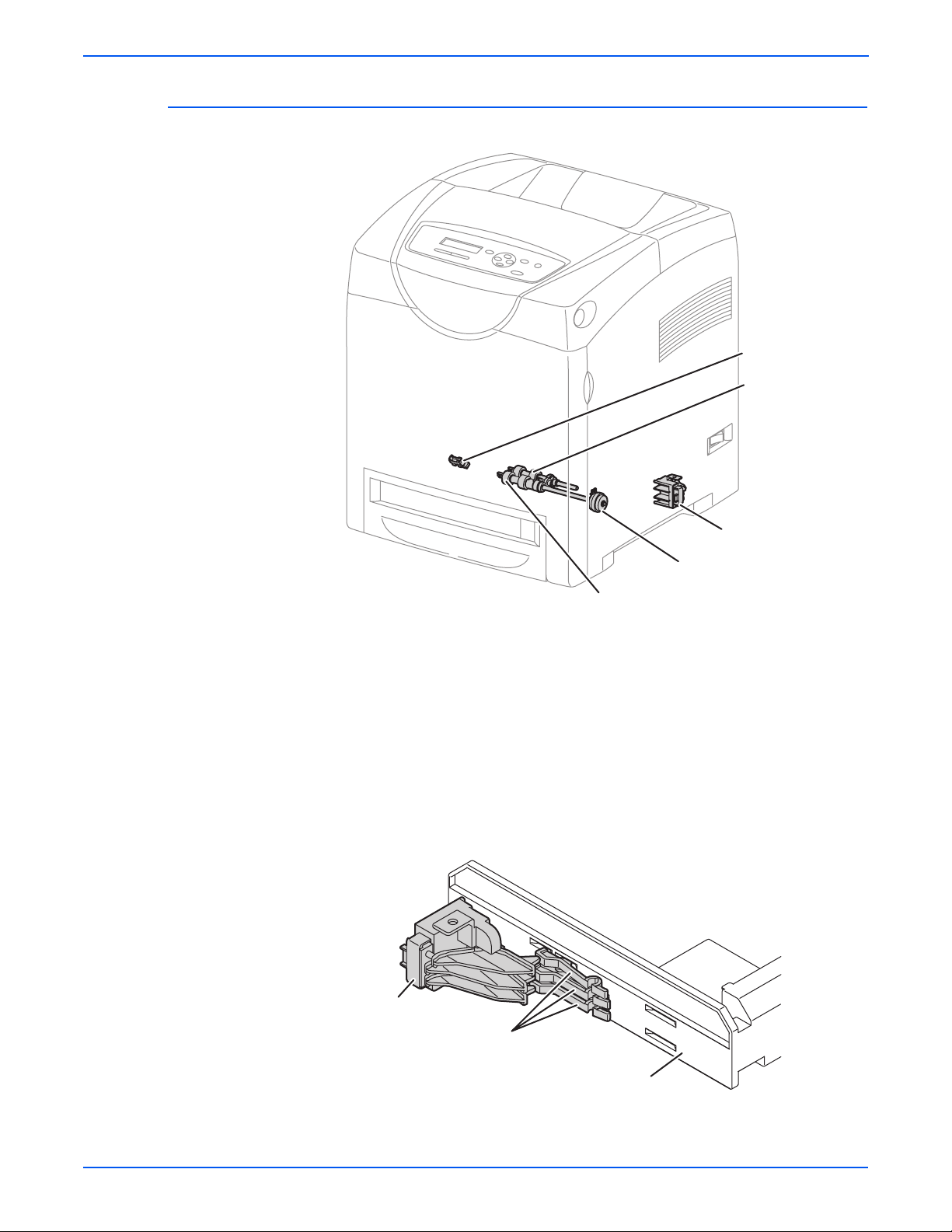
Theory of Operation
Paper Feeder
No Paper Sensor
Feed Roller
(Nudger Roller)
Paper Size Switch
Tray 2 Feed Clutch
Feed Roller (Takeaway Roller)
■ Tray 2 Feed Roller
The Feed Roller (Takeaway Roller) feeds the paper when the Feed Clutch
operates.
■ Tray 2 Feed Clutch
The Feed Clutch transmits drive energy from the Drive Assembly to the
Feed Roller.
■ Tray 2 Size Switch
The Size Switch detects the presence and size of the paper in the tray.
s6180-265
Size Switch
Size Switch Actuator
Tray End Guide
s6180-150
2-20 Phaser 6180 Color Laser Printer Service Manual
Page 71

■ Tray 2 End Guide
Not
The paper size is detected at the End Guide position.
Tray 2 End Guide
A5 (SEF)
B5 (SEF)
Executive (SEF)
Letter (SEF)
Legal 14" (SEF)
A4 (SEF)
Legal 13" (SEF)
Theory of Operation
All paper should be loaded SEF.
s6180-149
e
Refer to “Paper Size Detection” on page 2-50 for detailed information on
paper size switches and paper size.
■ Tray 2 No Paper Sensor
The No Paper Sensor detects the presence of the paper in the tray based
on the Tray 2 No Paper Actuator position.
No Paper Sensor
No Paper Actuator
Actuator (No Paper Position)
s6180-151
Phaser 6180 Color Laser Printer Service Manual 2-21
Page 72

Theory of Operation
Not
Tray 1 (MPT) & Registration
Rubber
Registration Roller
Turn Roll
Metal Registration Roller
Registration Sensor
Registration Clutch
Turn Clutch
Tray 1 (MPT) Feed Roller
Tray 1 (MPT) No Paper Sensor
■ Tray 1 (M P T) Turn C l utch
Tray 1 (MPT) Feed Solenoid
Tray 1 (MPT) Gear
s6180-268
The Turn Clutch transmits drive energy from the Drive Assembly to the
Tur n R o l l e r.
■ Tray 1 (MP T ) Turn Roll e r
The Turn Roller is rotated by the drive from the Drive Assembly through
the Turn Clutch to feed paper from the Tray 1 (MPT) or duplex paper path
to the Registration Chute.
■ Tray 1 (MPT) Registration Sensor
The Registration Sensor detects paper when the paper leading edge
reaches the Registration Chute. When paper is fed from Tray 1 (MPT), the
Registration Sensor measures the paper length. The On time of the
Registration Sensor is converted into the paper length.
e
On: The paper activates the Actuator.
■ Tray 1 (MPT) Registration Clutch
The Registration Clutch transmits drive energy from the Main Drive to the
Registration Rubber Roller, and transports paper from Tray 1 (MPT) and
the duplex path to the Print Cartridge direction. The timing of sheets
feeding from the Registration is adjusted by the duration of the
Registration Clutch operation so that the toner image on the drum can be
transferred to the appropriate position on the sheet.
2-22 Phaser 6180 Color Laser Printer Service Manual
Page 73

Theory of Operation
■ Tray 1 (MPT) Feed Solenoid
The Feed Solenoid controls drive energy from the Drive Assembly to the
Tray 1 (MPT) Feed Roller.
Tray 1 (MPT) Feed Roller
Tray 1 (MPT) Feed Solenoid
Retard Roller
Drive Assembly
■ Tray 1 (MPT) No Paper Sensor
s6180-266
The No Paper Sensor detects the presence of paper in Tray 1 (MPT)
based on the Actuator’s position.
Tray 1 (MPT) No Paper
Sensor
Tray 1 (MPT) No Paper
Sensor
Paper
No Paper Actuator
No Paper Actuator
s6180-267
Phaser 6180 Color Laser Printer Service Manual 2-23
Page 74
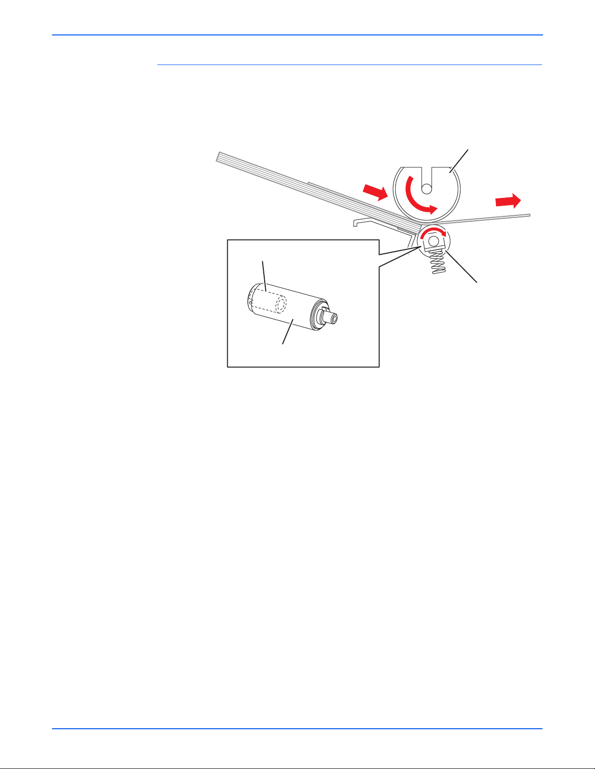
Theory of Operation
Multiple Sheet Feed Prevention
The sheets loaded in Tray 1 (MPT) are occasionally stuck together at the
edges, which can cause a multiple sheet feed or a jam. Normally, when only
one sheet is fed, both the Feed Roller and Retard Roller rotate to allow the
sheet to pass.
Tray 1 (MPT) Feed Roller
Torque Limiter
Retard Roller
Retard Roller
Single Feed
s6180-499
2-24 Phaser 6180 Color Laser Printer Service Manual
Page 75
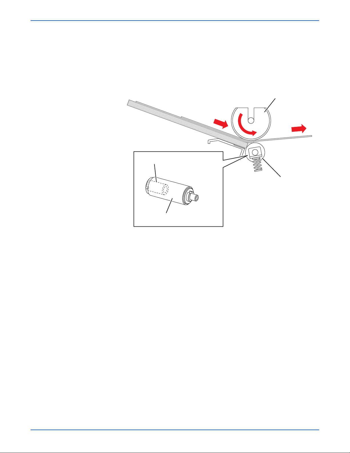
Theory of Operation
However, when two sheets are fed concurrently, only the Feed Roller rotates.
The Retard Roller is coupled to a friction clutch that prevents the roller from
rotating due to the extra force from feeding two sheets; this process allows the
upper sheet to pass by as the lower sheet is stopped by the friction with the
Retard Roller at rest.
The Retard Roller is pushed toward the Feed Roller by spring pressure, and
controlled by the Torque Limiter (Friction Clutch Retard) with which it is
coupled.
Tray 1 (MPT) Feed Roller
Torque Limiter
Retard Roller
Retard Roller
Multiple Feed
s6180-269
Phaser 6180 Color Laser Printer Service Manual 2-25
Page 76

Theory of Operation
Lead Edge Registration
When a sheet is fed from Tray 1 (MPT) to the toner transfer position, the
registration of the sheet may not be correctly maintained due to misalignment
of lead edges in the tray.
To avoid this problem, the lead edge position needs to be aligned at the
Registration rollers before the sheet is fed in front of the Transfer Unit Belt, or
in front of the BTR’s.
Registration Rollers
s6180-270
Before the Registration rollers are energized, the paper is advanced from the
tray to the rollers. This process aligns the leading edge as shown below.
By pushing the edge of the sheet coming out of Tray 1 (MPT) against the
Registration Roller that is not turning, the lead edge of the sheet is registered.
Registration Rollers
Skewed Paper
s6180-271
2-26 Phaser 6180 Color Laser Printer Service Manual
Page 77

Paper Detection
Since the paper path from Tray 1/Duplex to the Registration Sensor and from
the paper tray to the Registration Sensor are different, the Registration
Sensor is provided with Actuators A and B.
■ Actuator A detects the sheet fed from Tray 1/Duplex.
■ Actuator B detects the sheet fed from the paper tray.
The movement of Actuator A does not affect Actuator B.
Theory of Operation
Registration Sensor
Actuator B
Registration Sensor Spring (B)
Actuator A
Registration Sensor Spring (A)
Normal Position
Actuator B
Registration Sensor
Actuator A
From Tray 1 (MPT) or Duplex
Registration Sensor
Paper
Actuator A
From Paper Tray
Registration Sensor
Paper
Actuator A
Actuator B
s6180-272
Phaser 6180 Color Laser Printer Service Manual 2-27
Page 78

Theory of Operation
Fuser
Exit Sensor
Rear View
Temperature
Sensor (STS)
Exit Roller
Pressure Belt
Temperature
Sensor (NCS)
Heat Roller
Thermostat
Fuser
Front
Heater Lamp
Transfer Unit
ADC Sensor
ESA Roller
s6180-276
The Fuser fixes transferred toner onto the paper using heat and pressure and
feeds the paper before and after toner is fixed. The Fuser consists of the
following components: Heat Roller, Heater Lamp, Thermostat, Temperature
Sensor, Pressure Belt, Exit Roller, and Exit Sensor.
■ Heat Roller
The Heat Roller is a metal tube with coated surface and a Heater inside.
As the paper passes between the Heat Roller and Pressure Belt, heat
that is applied to the paper, melts the toner, and fuses it to the paper.
2-28 Phaser 6180 Color Laser Printer Service Manual
Page 79

Theory of Operation
■ Heater Lamp
The Heater Rods are glass tubes containing heater coils. The Main
Heater Lamp heats the entire length of the Heat Roller, and the Dual SubHeater Rods heat the center.
■ Thermostat
The Thermostat provides a second-level of protection. If the Heat Roller
temperature exceeds the current temperature, the Thermostat cuts off the
AC power to the Heater Lamps.
■ Temperature Sensors
The temperature sensors are thermistors having a known value of
resistance that varies with temperature. There are two Temperature
Sensors. The Soft Touch Sensor (STS) is located at the edge of the
Heater Lamp, and the Non-Contact Sensor (NCS) is located at the center
of the Fuser. The sensors monitor temperature of each location to control
lighting of the Heater Lamp. The Sensors are mounted in contact with the
surface of the Heat Roller. Power to the Heater Lamp is turned On and Off
using the signals from these sensors, so that the surface temperature of
the Heat Roller can be maintained within a specified range. This signal is
also used to provide a first stage of overheat protection.
■ Pressure Belt
The Pressure Belt maintains pressure on the paper passing between it
and the Heat Roller. The pressure bonds the melted toner to the paper.
■ Exit Roller
The Exit Roller transports paper from the Fuser to the output tray.
■ Exit Sensor
The Exit Sensor detects passage of printed pages after fusing on the
Actuator’s position changes.
Phaser 6180 Color Laser Printer Service Manual 2-29
Page 80

Theory of Operation
Transfer Unit
The Transfer Unit consists of the Belt, ADC Sensor, ADC Solenoid, ADC Pad,
and ESA Roller.
Normal Position
ADC Solenoid
ADC Solenoid On
Position of ADC Sensor
Position of ADC Sensor
(Window = Open)
Spring
Shutter
ADC Pad
ADC Pad
ADC Sensor
s6180-273
■ Belt
The Belt feeds the paper toward the direction of the Fuser.
■ ADC Sensor
The ADC Sensor detects the toner patches on the Belt and converts them
to voltage value. The voltage value is used to control the density of toner.
■ ADC Solenoid
To activate the ADC Pad, turn On the ADC Solenoid for a fixed time
before the ADC Sensor starts reading the toner patches. When turned
On, the ADC Solenoid activates the ADC Pad, which cleans
contamination on the ADC Sensor surface.
■ ESA Roller
The ESA Roller discharges a positive voltage to the paper. Toner transfer
efficiency is raised by applying a positive charge to the paper.
2-30 Phaser 6180 Color Laser Printer Service Manual
Page 81
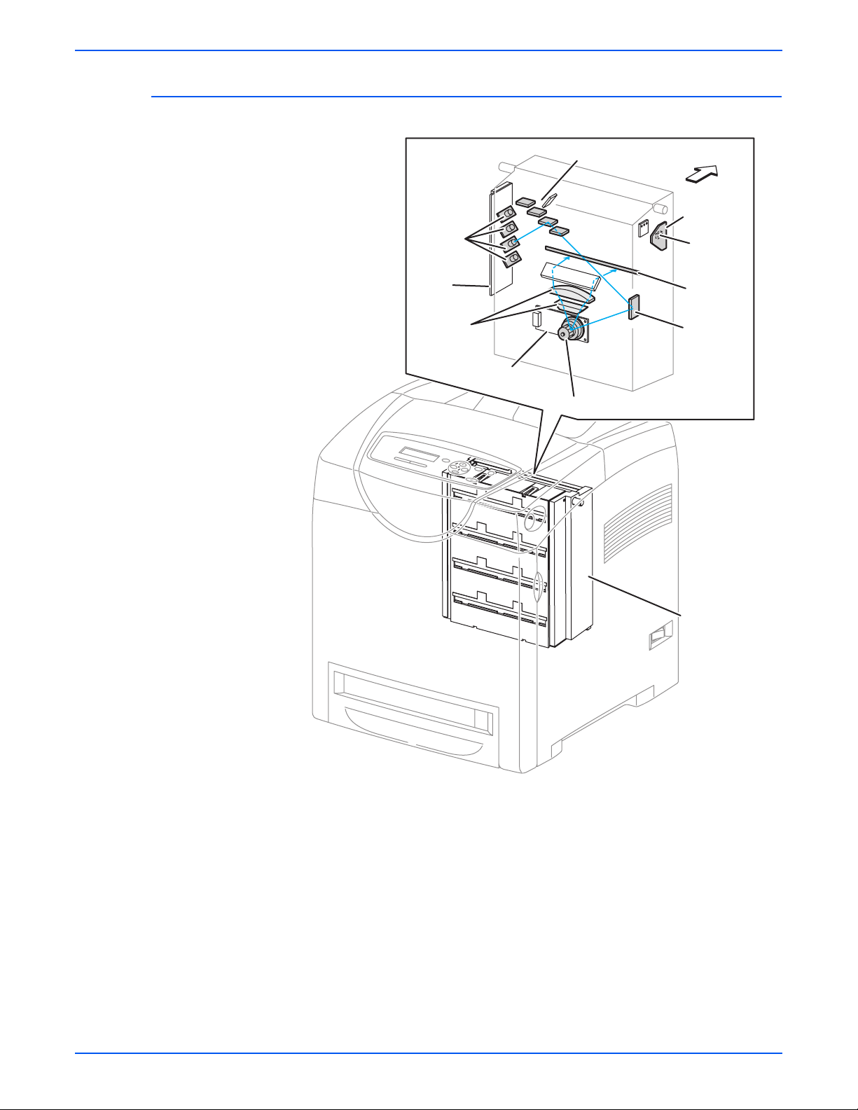
Laser Unit
Theory of Operation
Rear View
Laser
Diodes
Laser
Diode
Board
Lens
Scanner
Mirror
Polygon Mirror
Front
SOS Board
SOS
Sensor
Window
Mirror
Laser Unit
s6180-277
The Laser Unit is an exposure unit that generates laser beams to form
electrostatic latent image on the drum surface. The Laser Unit consists of the
following components: Laser Diode (LD), Scanner, Start of Scan (SOS)
Board, Lenses, Mirror, and Window.
Phaser 6180 Color Laser Printer Service Manual 2-31
Page 82

Theory of Operation
■ Laser Diode Board
There are four Laser Diodes which produce laser beams that are turned
On and Off according to the print data signal.
The Laser Diode Board is comprised of four LDs corresponding to C, M,
Y, and K. Each LD converts the electric signals of incoming image data
into laser waves. In order to stabilize the laser light quantity during
formation of an electrostastic latent image, the LD Board monitors the
intensity of the laser beam to adjust it to the appropriate level. This
process is called Auto Power Control (APC).
■ Scanner
The Scanner is comprised of a Scanner Motor that rotates at a constant
speed and a Polygon Mirror that is mounted on the Motor Shaft. The laser
light output from the LD is irradiated onto the Polygon Mirror via the
Mirror. The Polygon Mirror, provided with six reflecting mirror faces,
changes the reflection angle of the laser light as it rotates by the Scanner
Motor, thereby allowing the laser light to scan the drum along its axial
direction. Scanning is performed using one reflecting mirror face for each
line.
■ Start of Scan (SOS) Board
The SOS Sensor on the SOS Board converts incoming laser beam, upon
detection, to an electric signal as reference for starting scanning, and
transmits this signal to the MCU Board. The SOS sensor signals are used
to synchronize the starting point of the laser beam scanning with the
starting point of the image writing.
■ Lenses
The laser light reflected from the Polygon Mirror reaches the drum surface
via the Lenses, Mirror, and Window. The Lenses correct aberration.
■ Mirror
The Mirror directs the laser beam and secure an optical path.
■ Window
The window prevents debris from entering the Laser Unit.
2-32 Phaser 6180 Color Laser Printer Service Manual
Page 83

Print Cartridge
Theory of Operation
Print Cartridge (K)
Print Cartridge (C)
Dispenser (K)
Dispenser (C)
LED
Dispenser (M)
Dispenser (Y)
Print Cartridge (M)
Print Cartridge (Y)
CRUM Connector (K)
CRU Sensor (K)
CRUM Connector (C)
CRU Sensor (C)
CRUM Connector (M)
CRU Sensor (M)
CRUM Connector (Y)
CRU Sensor (Y)
s6180-280
The Print Cartridge is a customer replaceable item consists of the following
components:
■ Customer Replaceable Unit Memory (CRUM) Connector
The CRUM Connector reads and writes the CRUM data. Printer specific
information is stored in the CRUM.
■ Dispenser (C/M/Y/K)
The Dispenser provides drive energy to the Agitator and Auger in the Print
Cartridge, and provides toner to the Developer part of the Print Cartridge.
Phaser 6180 Color Laser Printer Service Manual 2-33
Page 84

Theory of Operation
■ CRU Sensor (C/M/Y/K)
The CRU Sensor detects the presence of the Print Cartridge.
CRU Sensor Actuator
(No Cartridge Position)
CRU Sensor Actuator
(Cartridge in Position)
Print Cartridge Sensor (C, M, Y, K)Print Cartridge Sensor (C, M, Y, K)
Print Cartridge
■ Erase Lamp (LED)
The light of the LED passes through the lens of the Print Cartridge,
illuminates the drum, and eliminates the charge on the drum.
Erase Lamp
LED Drum Print Cartridge
Erase Lens
CRU Sensor
s6180-278
s6180-279
2-34 Phaser 6180 Color Laser Printer Service Manual
Page 85

Main Drive
Not
Theory of Operation
Main Drive
Exit Clutch
Main Motor
Sub Motor
Developer
Motor
Tray 2 Motor
Drive Assembly
s6180-281
The Main Drive provides drive energy to the following components:
■ Main Motor
The Main Motor provides drive energy for the Black Drum, Transfer Unit,
and Fuser.
■ Sub Motor
The Sub Motor provides drive energy for the Black Developer, Cyan,
Magenta, and Yellow Drums.
■ Developer Motor
The Developer Motor provides drive energy for the Cyan, Magenta, and
Yellow Developers.
■ Exit Clutch
The Exit Clutch transmits drive energy from the Main Motor to the Exit
Roll in the Fuser. When Duplex mode is in use, the Exit Clutch stops. The
Exit Roll is driven by the Duplex Motor.
■ Drive Assembly
The Drive Assembly provides drive energy for Tray 1 (MPT), Tray 2, and
Registration. The Tray 2 Motor is part of the Drive Assembly.
e
Refer to “Mechanical Components” on page 2-56 for detailed diagrams.
Phaser 6180 Color Laser Printer Service Manual 2-35
Page 86

Theory of Operation
Electrical
Interlock Switch
Humidity/Temperature
Sensor
Control Panel
HVPS
Humidity/Temperature
Sensor
Interlock Switch
Main Fan
LVP S
Power Switch
EEPROM Board
Image Processor Board
MCU Board
s6180-282
Control Panel
The Control Panel displays the printer status and operates the printer.
Ready
CMYK
s6180-458
Power Switch
The Power Switch turns the printer AC Power Supply On/Off.
2-36 Phaser 6180 Color Laser Printer Service Manual
Page 87

Theory of Operation
Main Fan
The Main Fan removes heat from the printer to prevent overheating.
Electrically Erasable Programmable Read-Only Memory (EEPROM) Board
The EEPROM Board stores the printer unique information. Information on the
EEPROM Board is also stored on the Machine Control Unit (MCU) Board.
Humidity /Temperature Sensor
The Humidity/Temperature Sensor reads the humidity and temperature within
the printer.
Interlock Switch
The Interlock Switch is a switch that cuts the +24 VDC power supply to the
HVPS or Motor upon the opening of the Front Cover.
Low-Voltage Power Supply (LVPS)
Two types of LVPS are available: 100/120V and 230V. The LVPS supplies AC
power from the power source to the Fuser Heater; the LVPS also generates
and supplies stable low-voltage DC power used for the logic circuit. The LVPS
contains a control circuit for the heater of the Fuser, in addition to the power
circuit.
s6180-459
Phaser 6180 Color Laser Printer Service Manual 2-37
Page 88

Theory of Operation
High-Voltage Power Supply (HVPS)
The HVPS provides high-voltage power to the components in the Transfer
Unit and Print Cartridge to perform charging, development, and primary
transfer of the print process to the BCR, BTR, Developer, and ESA Roller.
s6180-461
2-38 Phaser 6180 Color Laser Printer Service Manual
Page 89

Image Processor Board
The Image Processor (I/P) Board is connected to the MCU Board, which
controls the printer, including Diagnostic, Interface, and Image
Processing. The I/P Board is one of the major elements of the Phaser
6180 Printer.
The primary function of the I/P Board is to receive host data through one
of the following available ports (Parallel, USB, or Ethernet). The received
host data is buffered, stored, and sent to the print engine in a rasterized
format.
1. Standard Memory (128 MB on-board RAM)
2. Optional Memory DIMM (should be swapped)
3. Multi-Protocol Network Card Connection
4. NVRAM
5. Ethernet Connection
6. PC Interface Connection (Parallel)
7. USB Connection
Theory of Operation
4
5
6
1
7
23
s6180-450
When installing a new I/P Board in the printer, you must transfer the
following parts from the old board to the new board:
■ Memory DIMM (if installed)
■ NVRAM
■ Multi-Protocol Network Card (if installed)
Phaser 6180 Color Laser Printer Service Manual 2-39
Page 90

Theory of Operation
Not
Machine Control Unit Board
The Machine Control Unit (MCU) Board controls the printing process based
on the communication with the printer Image Processor Board and
information from the Sensors or Switches. Major functions include:
1. Communicates with the Image Processor Board.
2. Receives information from the Sensors or Switches.
3. Controls the Motors in the Main Drive and Drive Assembly.
4. Distributes low-voltage DC power generated from the LVPS to each
component.
5. Controls the Laser Unit.
NVRAM
s6180-460
e
When replacing an MCU Board, ensure to transfer the NVRAM from the
old MCU Board to the new MCU Board.
2-40 Phaser 6180 Color Laser Printer Service Manual
Page 91
Data Flow
Theory of Operation
The electrical signal flow for the print data from the printer I/P Board is shown
in the following diagram.
Computer
I/P Board
MCU Board
Laser Unit
Print
Cartridges (4x)
Print
Cartridges (4x)
Host (Electric Signal)
Electronic Sub-system Control Board (Electric Signal)
Machine Control Unit (Electric Signal)
Laser Unit (Laser Beams)
Electrostatic Latent On Drum (Invisible Image)
Toner Image On Drum
Transfer Unit
Fuser
Toner Image On Paper
Print Image On Paper
s6180-283
Phaser 6180 Color Laser Printer Service Manual 2-41
Page 92

Theory of Operation
Duplex Unit
Duplex Fan
Upper Duplex Roller
Duplex Board
Duplex Jam Sensor
Duplex Clutch
Duplex Motor
Lower Duplex Roller
■ Duplex Jam Sensor
s6180-284
The Duplex Jam Sensor detects paper that is carried to the Duplex Unit.
■ Duplex Clutch
The Duplex Clutch transmits drive energy from the Duplex Motor to the
Exit Roller in the Fuser. When the Clutch operates, the Exit Roller rotates
in the reverse direction.
■ Duplex Motor
The Duplex Motor provides drive energy to the Lower Roller (Duplex 2
Roller), Upper Roller (Duplex 1 Roller), and Exit Roll on the Fuser.
■ Duplex Board
The Duplex Board controls the Motor, Sensor, and Clutch.
■ Duplex Fan
The Duplex Fan removes heat from inside of the printer to prevent
overheating.
2-42 Phaser 6180 Color Laser Printer Service Manual
Page 93

Tray 3 - Optional 550-Sheet Feeder
Tray 3 Function
Left Side Guide
Theory of Operation
Bottom Plate
Tray 3 End Guide
Right Side Guide
Retard Roller
■ Tray 3 Side Guide (Left/Right)
The Left/Right Guide moves at a right angle to the paper transfer direction
to align the paper width.
■ Tray 3 End Guide
The End Guide moves toward the paper direction to determine the paper
size. The Size Switch On/Off switch varies according to the Tray 3 End
Guide position to detect the paper size.
■ Tray 3 Retard Roller
The Retard Roller and the Feed Roller (Pick Up Unit) pinch the paper to
feed.
s6180-260
Phaser 6180 Color Laser Printer Service Manual 2-43
Page 94
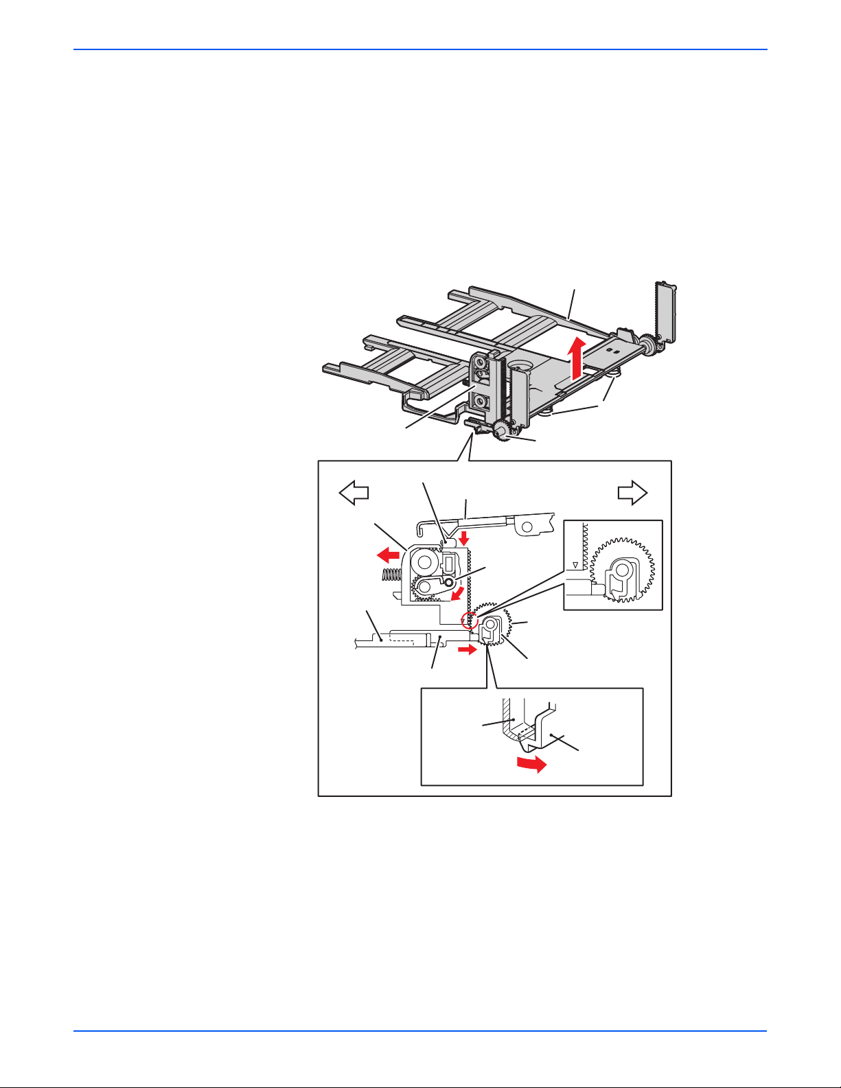
Theory of Operation
■ Tray 3 Bottom Plate
a. When the tray is inserted into the Sheet Feeder, the Actuator is
pushed toward the front by the Left Guide, which pushes the Stopper.
b. The Stopper unlocks the Bottom Lock Oneway Gear.
c. When the tray is pushed until it stops, the Bottom Lock Lever is
pressed down by the Support Nudger in the Feeder.
d. The Bottom Lock Lever actuates the Bottom Lock Lever Gear, which
pushes the Bottom Rack Lock toward the rear.
e. The gear on the Bottom Rack Lock is disengaged from the Bottom
Lock Oneway Gear, which allows the Bottom Plate to raise up by the
Bottom Up Springs.
Bottom Plate
Bottom Up Spring
Bottom Rack Lock
Bottom Lock Oneway Gear
Bottom Lock Lever
Bottom Rack Lock
e
Left Guide
Actuator
Support Nudger
c
Bottom Lock
Lever Gear
d
a
Lock Part
(Tray Housing)
Front of TrayRear of Tray
Bottom Lock
Oneway Gear
Stopper
Stopper
b
s6180-285
2-44 Phaser 6180 Color Laser Printer Service Manual
Page 95
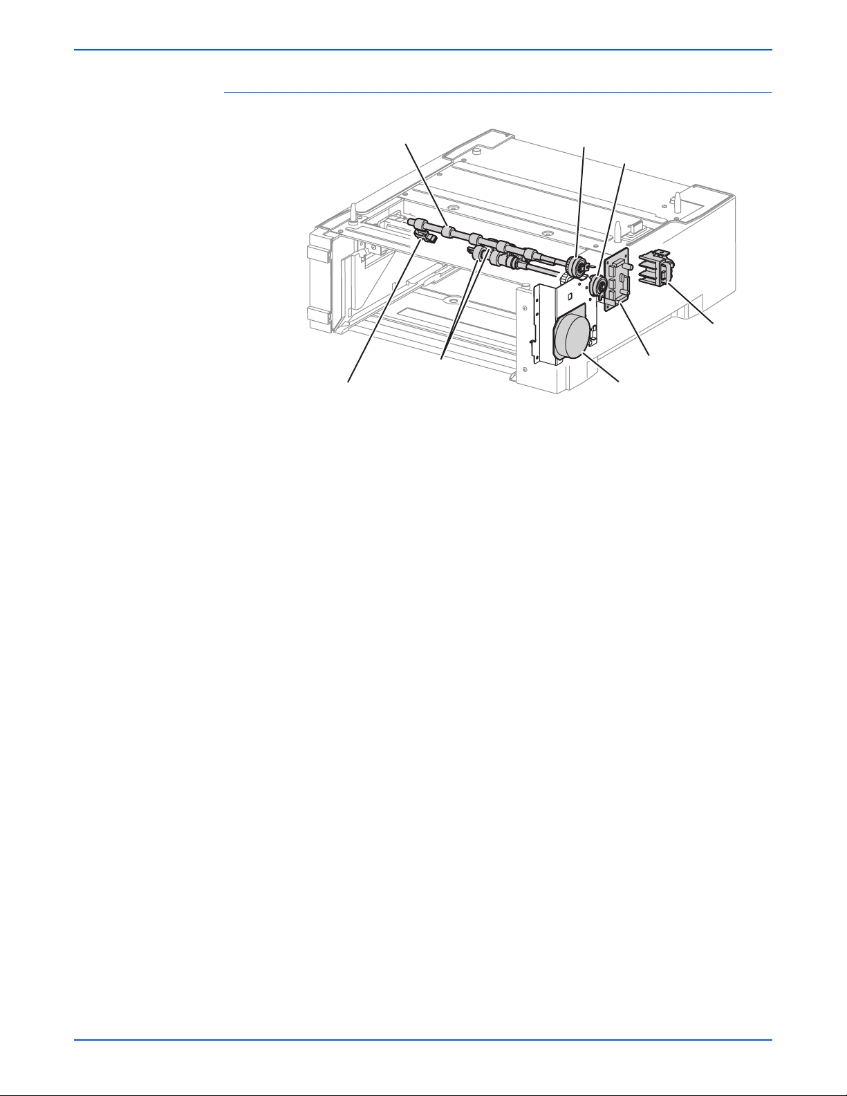
Optional 550-Sheet Feeder
Theory of Operation
Turn Roller
Feed Roller
Tray 3 No Paper Sensor
■ Tray 3 No Paper Sensor
Turn Clutch
Feed Clutch
Size Switch
Optional Feeder Board
Optional Feeder Drive
The No Paper Sensor detects the presence of the paper in the paper tray
based on the No Paper Actuator position.
■ Tray 3 Feed Clutch
The Feed Clutch transmits drive energy from the Feeder Drive to the Feed
Roller.
s6180-286
■ Tray 3 Feed Roller
When the Feed Clutch operates, the Feed Roller rotates and feeds the
paper.
Phaser 6180 Color Laser Printer Service Manual 2-45
Page 96

Theory of Operation
Not
■ Tray 3 Turn Clutch
The Turn Clutch transmits drive energy from the Optional 550-Sheet
Feeder Drive through the Turn Clutch to feed the paper from the paper
tray to the printer.
■ Optional 550-Sheet Feeder Drive
The Optional 550-Sheet Feeder Drive drives the rollers of the Optional
Feeder.
■ Optional 550-Sheet Feeder Board
The Optional 550-Sheet Feeder Board controls the Motor, Sensor, and
Clutch.
■ Tray 3 Size Switch
The Size Switch detects the paper size and the presence of the paper
tray.
Size Switch
Size Switch Actuator
Tray End Guide
■ Tray 3 End Gu i de
Paper is detected at the Tray 3 End Guide.
Tray 3 End Guide
Executive (SEF)
Legal 14" (SEF)
All paper should be loaded SEF.
A4 (SEF)
Legal 13" (SEF)
Letter (SEF)
s6180-150
A5 (SEF)
B5 (SEF)
s6180-453
e
Refer to “Paper Size Detection” on page 2-50 for detailed information on
paper size switches and paper size.
2-46 Phaser 6180 Color Laser Printer Service Manual
Page 97

Tray 3 Multiple Sheet Feed Prevention
The sheets loaded in Tray 3 are occasionally stuck together along the edges,
which can cause a multiple sheet feed or a jam. The Nudger Roller feeds the
sheets to a position between the Feed Roller and the Retard Roller. Normally,
when only one sheet is fed, both the Feed Roller and Retard Roller rotate to
allow the sheet to pass.
Theory of Operation
Feed Roller (Takeaway Roller)
Friction Clutch
Feed Roller (Nudger Roller)
Retard Roller (Separator)
Retard Roller (Separator)
Single Feed
s6180-489
Phaser 6180 Color Laser Printer Service Manual 2-47
Page 98

Theory of Operation
However, when two sheets are fed concurrently, only the Feed Roller rotates.
The Retard Roller is coupled to a friction clutch that prevents the roller from
rotating due to extra force from feeding two sheets; this process allows the
upper sheet to pass by as the lower sheet is stopped by the friction with the
Retard Roller at rest.
The Retard Roller is pushed toward Feed Roller by spring pressure, and
controlled by the Friction Clutch with which it is coupled.
Friction Clutch
Feed Roller (Takeaway Roller)
Retard Roller (Separator)
Retard Roller (Separator)
Multiple Feed
Feed Roller (Nudger Roller)
s6180-147
2-48 Phaser 6180 Color Laser Printer Service Manual
Page 99

Printer Modes
Operational Modes
Theory of Operation
Power On
Initializing
Init CRU
Checking
Unit
Door Close
CRU Check
Wait
Cleaning
Motor Stop
Process Control
Cleaning
Exit Paper
Ready
Printing
&
Wait
Process Control
PFC
Process Control
Registration Control
Fuser Warming Up
Laser Warming Up
Fuser Cooling Down
Start Feeding
Error Occurred
Error
Motor Stop
Printing
& Wait
& Error
Exit Paper
Printing
Printing
Feed Jam Occurred
Life Over
&
Error
The Phaser 6180 Printer includes the following modes:
■ Diagnostics Mode
The printer is ready to receive diagnostic commands, or the printer
diagnostic function is operating.
Door Open
s6180-287
■ Wait Mode
The printer is preforming Print Quality adjustment.
■ Ready Mode
The printer is ready for printing.
■ Printing Mode
Printing is in progress.
■ Error Mode
An error is detected in the printer.
■ Initializing Mode
The printer is initializing with a new Developer Unit (new parts have been
installed into the printer).
■ Checking Unit Mode
The printer is checking consumable units.
Phaser 6180 Color Laser Printer Service Manual 2-49
Page 100
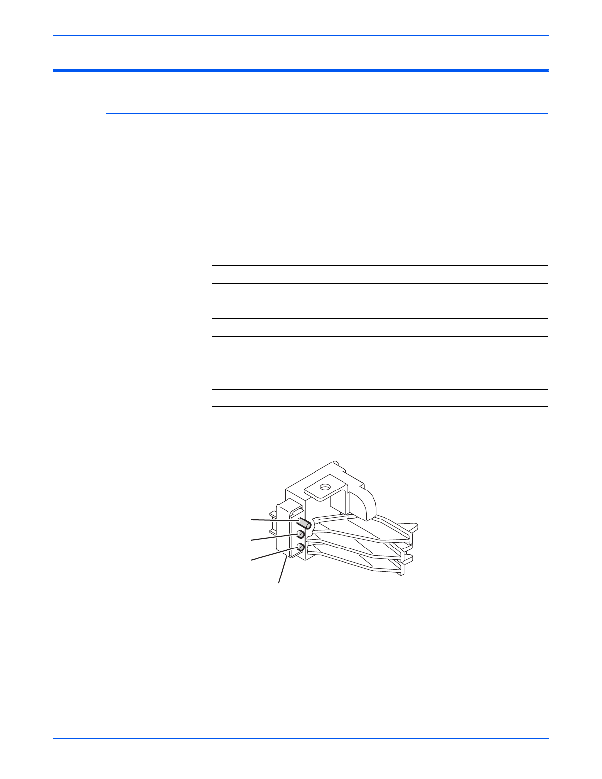
Theory of Operation
Not
Printer Control
Paper Size Detection
The paper size detection for Trays 2 and 3 is determined by three paper size
switches in each paper tray slot. The switch condition is set by moving the
paper guide in the tray. This in turn sets the plastic “fingers” on the side of the
paper tray to a specific position that activates the correct switch combination
for the selected paper size.
Paper Size Switches Indicated as SW1, SW2, and SW3
Paper Size
Letter (SEF) Off Off On
A4 (SEF) Off On On
A5 Off On Off
B5 (SEF) On Off Off
Legal 13” (SEF) On On On
Legal 14” (SEF) On On On
Executive (SEF) On Off On
No Tray Off Off Off
e
On: The Actuator is pushing the Size Switch.
Paper Size Switch
SW1 SW2 SW3
Switch 1
Switch 2
Switch 3
Size Switch
2-50 Phaser 6180 Color Laser Printer Service Manual
s6180-288
 Loading...