

Page 1

Xerox Nuvera
Digital Production System
Finishing
Solutions
Planning
Guide
December 2004
701P42973
Page 2

Xerox Corporation
Global Knowledge & Language Services
800 Philips Road Bldg. 845 – 17S
Webster, NY 14580
Copyright 2004 Xerox Corporation. All rights reserved.
Printed in the United States of America.
Please contact Xerox Feeding and Finishing with any comments or suggestions regarding the content
within this document:
xeroxfinishing@usa.xerox.com
Copyright protection claimed includes all forms and matters of copyrighted material and information now
allowed by statutory or judicial law of hereinafter granted, including without limitation, material generated
from the software programs that are displayed on the screen such as styles, icons, screen displays,
looks, etc.
Xerox, The Document Company, the digital X, the Xerox SquareFold Booklet Maker and Xerox
Nuvera Digital Production System are trademarks of, or licensed to, Xerox Corporation.
Other product names used herein are trademarks of their respective owners.
Page 3

Table of Contents
NTRODUCTION
1.
I
................................................................................................................................1-1
About this guide ................................................................................................................................1-1
Contents............................................................................................................................................. 1-1
EROX FINISHING TRANSPORT MODULE
2. X
(FTM) ............................................................................ 2-1
Product Overview.............................................................................................................................. 2-1
Performance Specifications......................................................................................................... 2-1
Limitations...................................................................................................................................... 2-1
System Dependencies and Prerequisites ..................................................................................... 2-2
Configuration Guide.......................................................................................................................... 2-2
Install Planning.................................................................................................................................. 2-3
Device Configurations .................................................................................................................. 2-3
Space Requirements.................................................................................................................... 2-3
Electrical Requirements............................................................................................................... 2-4
Environmental Requirements...................................................................................................... 2-4
Estimated Installation Time ......................................................................................................... 2-4
Operating Supplies ....................................................................................................................... 2-4
Customer Agreement ....................................................................................................................... 2-5
Devices........................................................................................................................................... 2-5
Primary Customer Applications .................................................................................................. 2-5
Special Considerations / Limitations.......................................................................................... 2-5
Upending / Stair Climbing............................................................................................................ 2-5
EROX DOCUMENT STACKER
3. X
5000 (DS5000) ............................................................................. 3-1
Product Overview.............................................................................................................................. 3-1
Performance Specifications......................................................................................................... 3-1
Limitations...................................................................................................................................... 3-1
System Dependencies and Prerequisites ..................................................................................... 3-2
Configuration Guide.......................................................................................................................... 3-2
Install Planning.................................................................................................................................. 3-3
Device Configurations .................................................................................................................. 3-3
Space Requirements.................................................................................................................... 3-3
Electrical Requirements............................................................................................................... 3-4
Environmental Requirements...................................................................................................... 3-4
Estimated Installation Time ......................................................................................................... 3-4
Operating Supplies ....................................................................................................................... 3-4
Customer Agreement ....................................................................................................................... 3-5
Devices........................................................................................................................................... 3-5
Primary Customer Applications .................................................................................................. 3-5
Special Considerations / Limitations.......................................................................................... 3-5
Upending / Stair Climbing............................................................................................................ 3-5
EROX SQUAREFOLD BOOKLETMAKER
4. X
(SQFBM)
WITH OPTIONAL COVER INSERTION MODULE
(CIM)....................................................................................................................................................... 4-1
Product Overview.............................................................................................................................. 4-1
Performance Specifications......................................................................................................... 4-1
Limitations...................................................................................................................................... 4-2
System Dependencies and Prerequisites ..................................................................................... 4-2
Configuration Guide.......................................................................................................................... 4-3
Install Planning.................................................................................................................................. 4-4
Device Configurations .................................................................................................................. 4-4
Space Requirements.................................................................................................................... 4-4
Electrical Requirements............................................................................................................... 4-5
Environmental Requirements...................................................................................................... 4-5
Estimated Installation Time ......................................................................................................... 4-6
Operating Supplies ....................................................................................................................... 4-6
Unique Features Set ........................................................................................................................ 4-7
Customer Agreement ....................................................................................................................... 4-8
I
Page 4

Table of Contents
Devices........................................................................................................................................... 4-8
Primary Customer Applications .................................................................................................. 4-8
Special Considerations / Limitations.......................................................................................... 4-8
Upending / Stair Climbing............................................................................................................ 4-8
5. C.P. B
ODULE
M
................................................................................................................................................... 5-1
OURG
BDFX B
OOKLET MAKER WITH OPTIONAL COVER FEEDER AND SQUARE EDGE
Product Overview.............................................................................................................................. 5-1
Performance Specifications......................................................................................................... 5-1
Limitations...................................................................................................................................... 5-2
System Dependencies and Prerequisites ..................................................................................... 5-2
Configuration Guide.......................................................................................................................... 5-3
Install Planning.................................................................................................................................. 5-4
Device Configurations .................................................................................................................. 5-4
Space Requirements.................................................................................................................... 5-4
Electrical Requirements............................................................................................................... 5-5
Environmental Requirements...................................................................................................... 5-5
Estimated Installation Time ......................................................................................................... 5-5
Operating Supplies ....................................................................................................................... 5-6
Unique Features Set ........................................................................................................................ 5-7
Customer Agreement ....................................................................................................................... 5-8
Devices........................................................................................................................................... 5-8
Primary Customer Applications .................................................................................................. 5-8
Special Considerations / Limitations.......................................................................................... 5-8
Upending / Stair Climbing............................................................................................................ 5-8
6. GBC F
USION PUNCH
WITH OFFSET STACKER
II
(FP II) ............................................................... 6-1
Product Overview.............................................................................................................................. 6-1
Performance Specifications......................................................................................................... 6-1
Limitations...................................................................................................................................... 6-1
System Dependencies and Prerequisites ..................................................................................... 6-2
Configuration Guide.......................................................................................................................... 6-2
Install Planning.................................................................................................................................. 6-3
Device Configurations .................................................................................................................. 6-3
Space Requirements.................................................................................................................... 6-3
Electrical Requirements............................................................................................................... 6-4
Environmental Requirements...................................................................................................... 6-4
Estimated Installation Time ......................................................................................................... 6-4
Operating Supplies ....................................................................................................................... 6-5
Unique Features Set ........................................................................................................................ 6-6
Customer Agreement ....................................................................................................................... 6-7
Devices........................................................................................................................................... 6-7
Primary Customer Applications .................................................................................................. 6-7
Special Considerations / Limitations.......................................................................................... 6-7
Upending / Stair Climbing............................................................................................................ 6-7
EROX DOCUMENT BINDER
7. X
120-D (DB120-D) ............................................................................ 7-1
Product Overview.............................................................................................................................. 7-1
Performance Specifications......................................................................................................... 7-1
Limitations...................................................................................................................................... 7-2
System Dependencies and Prerequisites ..................................................................................... 7-2
Configuration Guide.......................................................................................................................... 7-3
Install Planning.................................................................................................................................. 7-4
Device Configurations .................................................................................................................. 7-4
Space Requirements.................................................................................................................... 7-4
Electrical Requirements............................................................................................................... 7-5
Environmental Requirements...................................................................................................... 7-5
Estimated Installation Time ......................................................................................................... 7-5
Operating Supplies ....................................................................................................................... 7-6
II
Page 5

Table of Contents
Customer Agreement ....................................................................................................................... 7-7
Devices........................................................................................................................................... 7-7
Primary Customer Applications .................................................................................................. 7-7
Special Considerations / Limitations.......................................................................................... 7-7
Upending / Stair Climbing............................................................................................................ 7-7
TANDARD HORIZON PERFECT BINDER
8. S
Product Overview.............................................................................................................................. 8-1
Performance Specifications......................................................................................................... 8-1
System Dependencies and Prerequisites ................................................................................. 8-1
Install Planning.................................................................................................................................. 8-2
Device Configurations .................................................................................................................. 8-2
Space Requirements.................................................................................................................... 8-2
Electrical Requirements............................................................................................................... 8-3
Environmental Requirements...................................................................................................... 8-3
Estimated Installation Time ......................................................................................................... 8-3
Operating Supplies ....................................................................................................................... 8-3
Customer Agreement ....................................................................................................................... 8-4
Devices........................................................................................................................................... 8-4
Primary Customer Applications .................................................................................................. 8-4
Special Considerations / Limitations.......................................................................................... 8-4
Upending / Stair Climbing............................................................................................................ 8-4
OWIS PARKER FASTBACK MODEL 15XS
9. P
Product Overview.............................................................................................................................. 9-1
Performance Specifications......................................................................................................... 9-1
Limitations...................................................................................................................................... 9-1
System Dependencies and Prerequisites ..................................................................................... 9-1
Install Planning.................................................................................................................................. 9-2
Device Configurations .................................................................................................................. 9-2
Space Requirements.................................................................................................................... 9-2
Electrical Requirements............................................................................................................... 9-2
Environmental Requirements...................................................................................................... 9-2
Estimated Installation Time ......................................................................................................... 9-2
Operating Supplies ....................................................................................................................... 9-3
Customer Agreement ....................................................................................................................... 9-4
Devices........................................................................................................................................... 9-4
Primary Customer Applications .................................................................................................. 9-4
Special Considerations / Limitations.......................................................................................... 9-4
Upending / Stair Climbing............................................................................................................ 9-4
BQ-270X (BQ-270X) ..................................................... 8-1
.................................................................................... 9-1
III
Page 6

Table of Contents
IV
Page 7

Introduction
1. Introduction
The Solutions Planning Guide contains information on how to
prepare for the installation of In-line and Off-line Finishing
Devices to the Nuvera Digital Production System.
About this guide
This guide will provide the Analyst and the coordinating
Customer with pre-installation tasks for the specific Finishing
Device to be installed. The information provided in this guide
covers the following Finishing Devices:
• Xerox Finisher Transport Module (FTM)
• Xerox Document Stacker (DS5000)
• Xerox SquareFold Booklet Maker (SQFBM) with optional
Cover Insertion Module (CIM)
• Xerox Document Binder 120-D (DB 120-D)
• C.P. Bourg Document Finisher (BDFx) with optional Bourg
Cover Feeder (BCFx) and Square Edge module (SQEDG)
Contents
• GBC Fusion Punch II (FP II) with Offset Stacker
• Standard Horizon Perfect Binder BQ-270x (BQ-270x)
• Powis Parker Fastback® Model 15xs
This section lists the contents of this guide:
• Introduction - provides information about the use of this
Guide and it also lists the different Finishing Devices.
• Product Overview– provides a Product Overview,
Performance Specifications and Device / System Limitations.
• System Dependencies – lists what component elements and
upgrades are required.
• Configuration Guide - lists the various approved Finishing
Solution Configurations available.
• Install Planning- contains Space, Electrical and
Environmental requirements, for the different Finishing
Devices.
• Unique Features Set – provides information on each device
unique features.
• Customer Agreement – contains the Customer Agreement
form.
Note: For Document Finishing Architecture (DFA) profiles please
refer to the Nuvera DFA Resource Guide.
1-1
Page 8

Introduction
1-2
Page 9
Xerox Finishing Transport Module (FTM)
2. Xerox Finishing Transport Module (FTM)
Product Overview
This section will provide you with the features and capabilities of
the Finishing Transport Module.
The Finishing Transport Module enables in-line finishing by
providing document transport capability and full DFA Level 1
support to DFA compliant finishing devices.
Other features:
• Offers Dual DFA Exit Heights for flexible linking.
• Delivers Center or Edge registered output
• Provides 3 different output speeds to maximize Finishing
throughput capability
• Includes built-in Sheet Rotator to maintain productivity
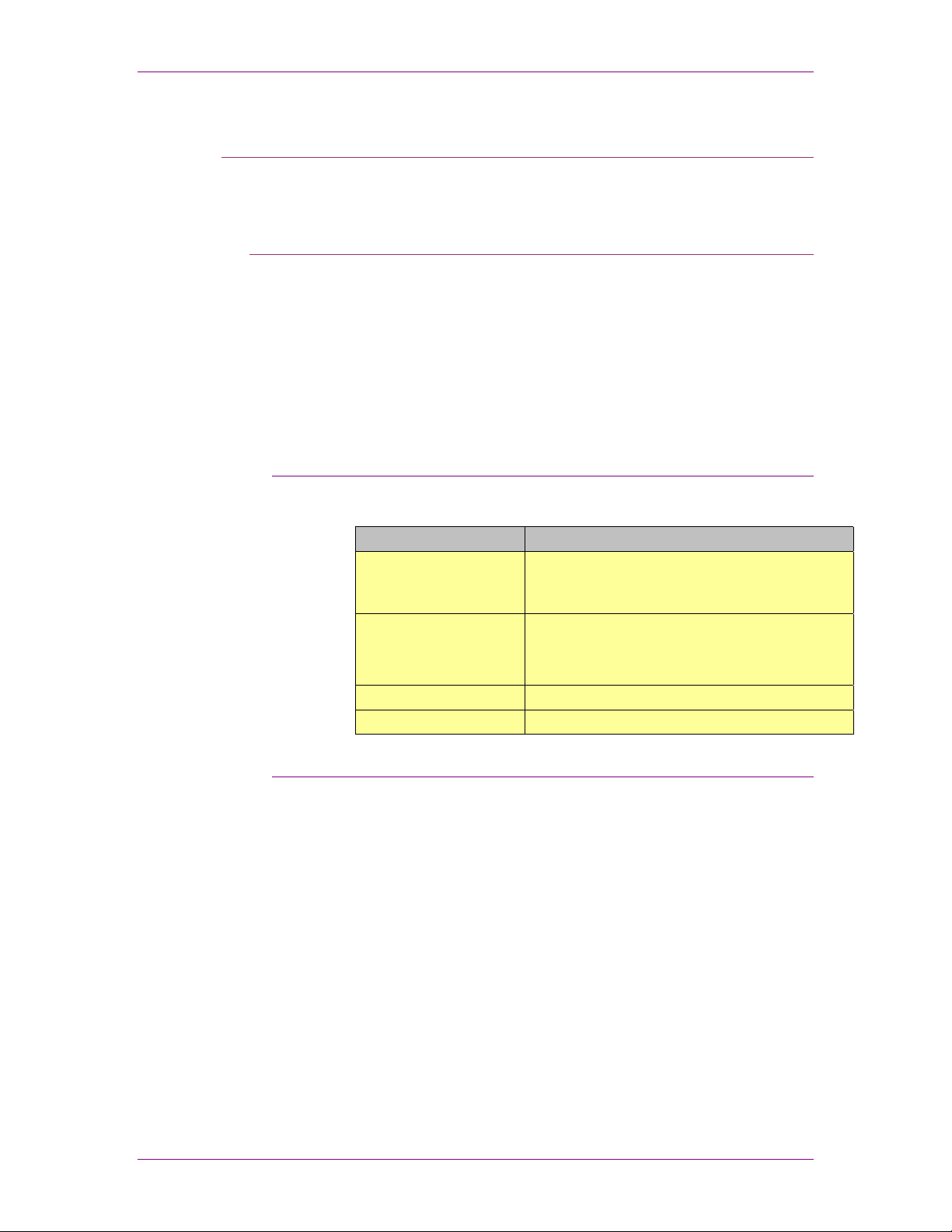
Performance Specifications
Listed below are the Performance Specifications for the Finishing
Transport Module.
Punching Specifications
Paper Size
Top Tray Capacity
Output Height
Input Height
Limitations
• Some marking may occur on recommended gloss coated
stocks with greater than 70% area coverage.
Top Tray: 5.5” x 8.27” (140 x 210 mm) – 12.6” x 18.5”
(320 x 470 mm)
Bypass with rotation: 7” x 10” (178 x 254 mm) – 12.6” x
14.3” (320 x 363 mm)
Bypass without rotation: 5.5” x 8.27” (140 x 210 mm) –
12.6” x 18.5” (320 x 470 mm)
250 (20 lb. Bond / 75 gsm)
34” (860 mm) and 40.2” (1021 mm)
34” (860 mm)
2-1
Page 10

Xerox Finishing Transport Module (FTM)
System Dependencies and Prerequisites
Listed below are the dependencies and prerequisites for
installing the FTM in-line with the Nuvera Digital Production
System.
• The Finisher Transport Module is required for in-line
connectivity to the printer.
Note: In case the floor at the customer site is very uneven, it is
recommended that the Nuvera IOT is installed and leveled with a
Caster Leveling Kit (kit number 498K07900).
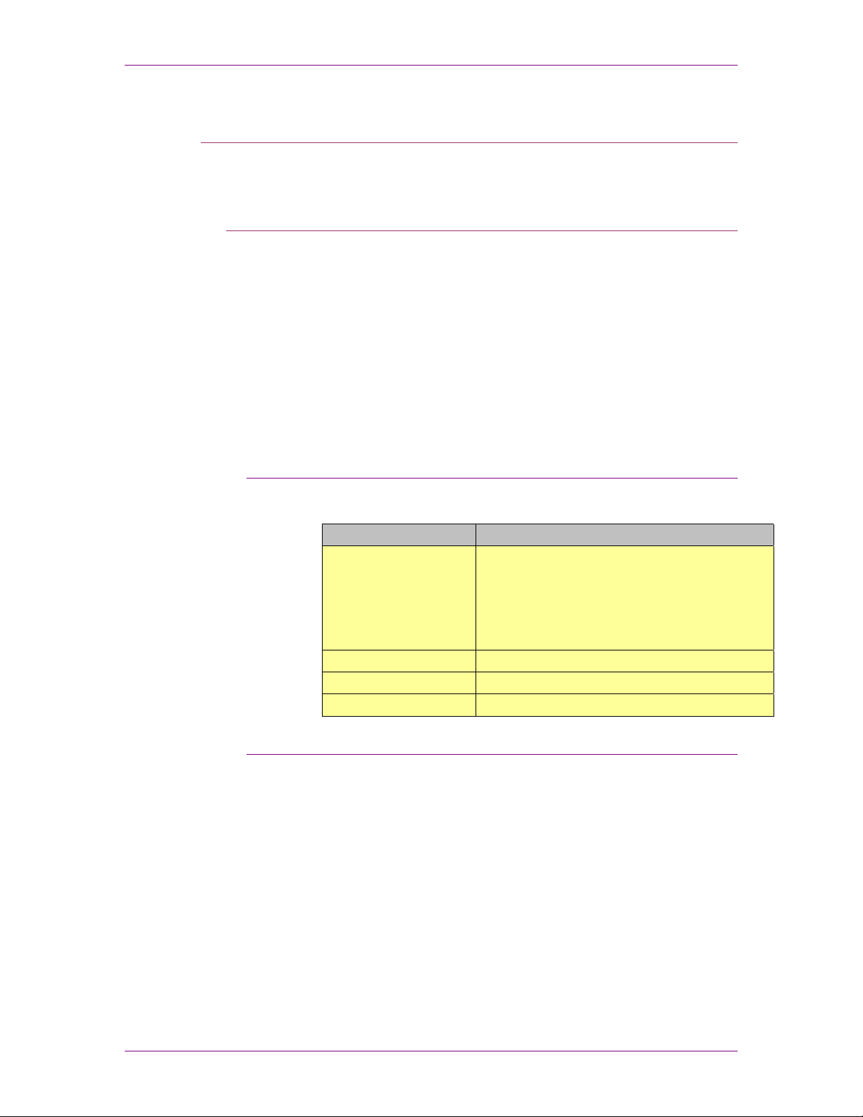
Configuration Guide
The diagram below identifies the different printer and finishing
solutions that are currently supported.
Printer Configurations Finisher Configurations
SFM IOT FTM
SFM SFM IOT
SFM IOT INS
SFM SFM IOT
FTM
FTM
INS FTM
DS5000
DS5000
DB120D
FP II
SQFBM
BDFX
DS5000
DS5000
DS5000 DS5000 BDFX DS5000 DS5000 BDFXBCFX
DS5000
DS5000
DB120D
DS5000
DS5000
BCFX BDFXBCFX SQEDG
BDFX DS5000
BDFX
FP II
SQFBM
BDFX
SQEDG
BDFXBCFXDS5000 DS5000 SQEDG
DS5000
DS5000
DS5000
DS5000
DS5000
DS5000
DB120D
SQFBM
DS5000
DS5000
FP II
BDFX SQEDG
DS5000
BDFXBCFX SQEDGBDFXBCFX
BDFX SQEDG
2-2
Page 11

Xerox Finishing Transport Module (FTM)
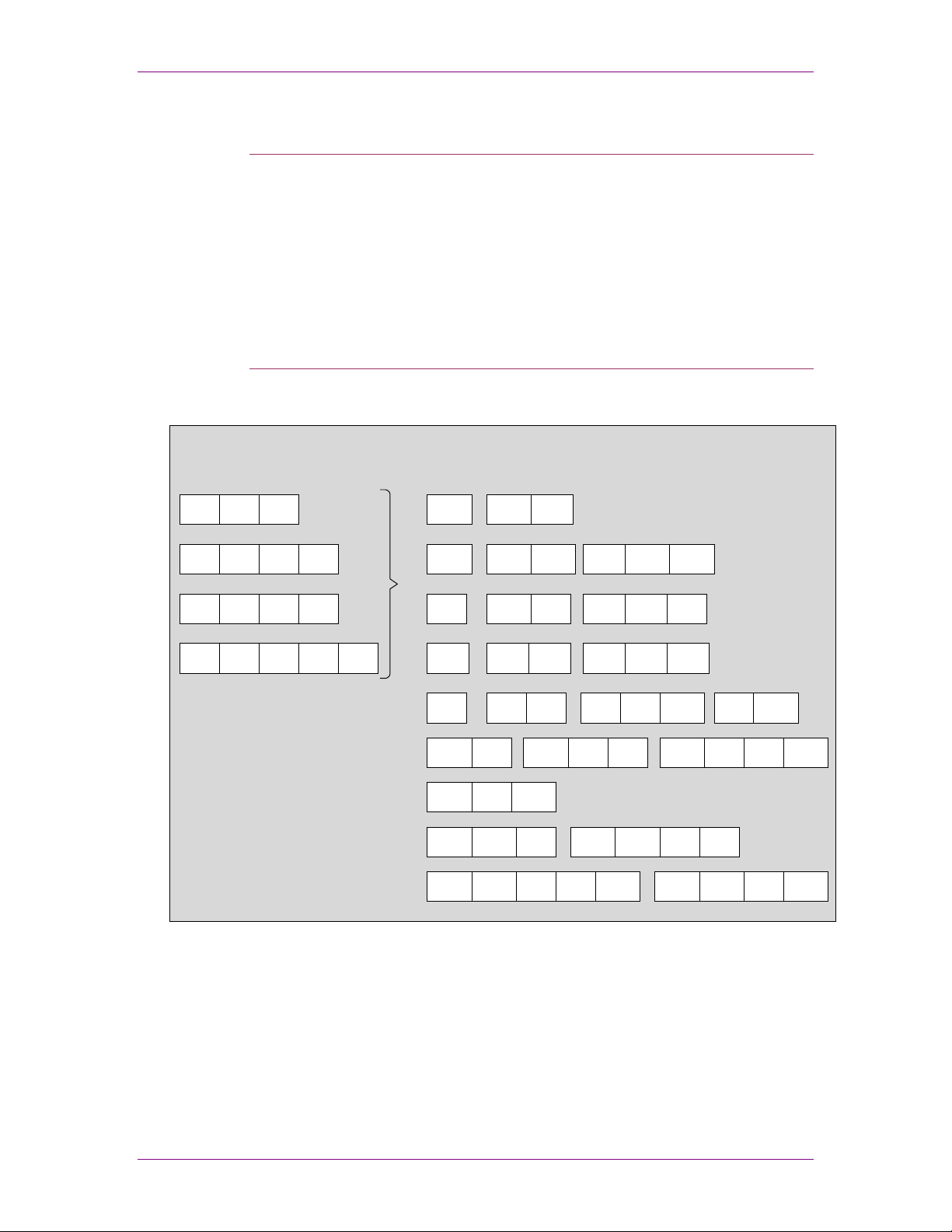
Install Planning
Device Configurations
Space Requirements
This Install Planning guide will help you prepare for the
installation of the Finisher Transport Module.
The Finisher Transport module components are:
• Finisher Transport Module, including built-in sheet rotator
The space requirements illustration provides machine footprint
as well as the overall operating and maintenance area.
In addition to the diagram below, there should be a minimum of
78 inches (1,981mm) clearance from the floor to the nearest
overhead obstruction.
Note: The FTM does not need any operating or maintenance
space on the right side of it as it will connect directly with a
downstream in-line Finishing Device.
30 inches
(763 mm)
Finishing
Transport
Module
30 inches
(763 mm)
28 inches
(711 mm)
35 inches
(889 mm)
In-line
Finishing
Device
Note: The space requirements diagram for the FTM is a
representation only and not drawn to scale.
88 inches
(2237 mm)
2-3
Page 12

Xerox Finishing Transport Module (FTM)
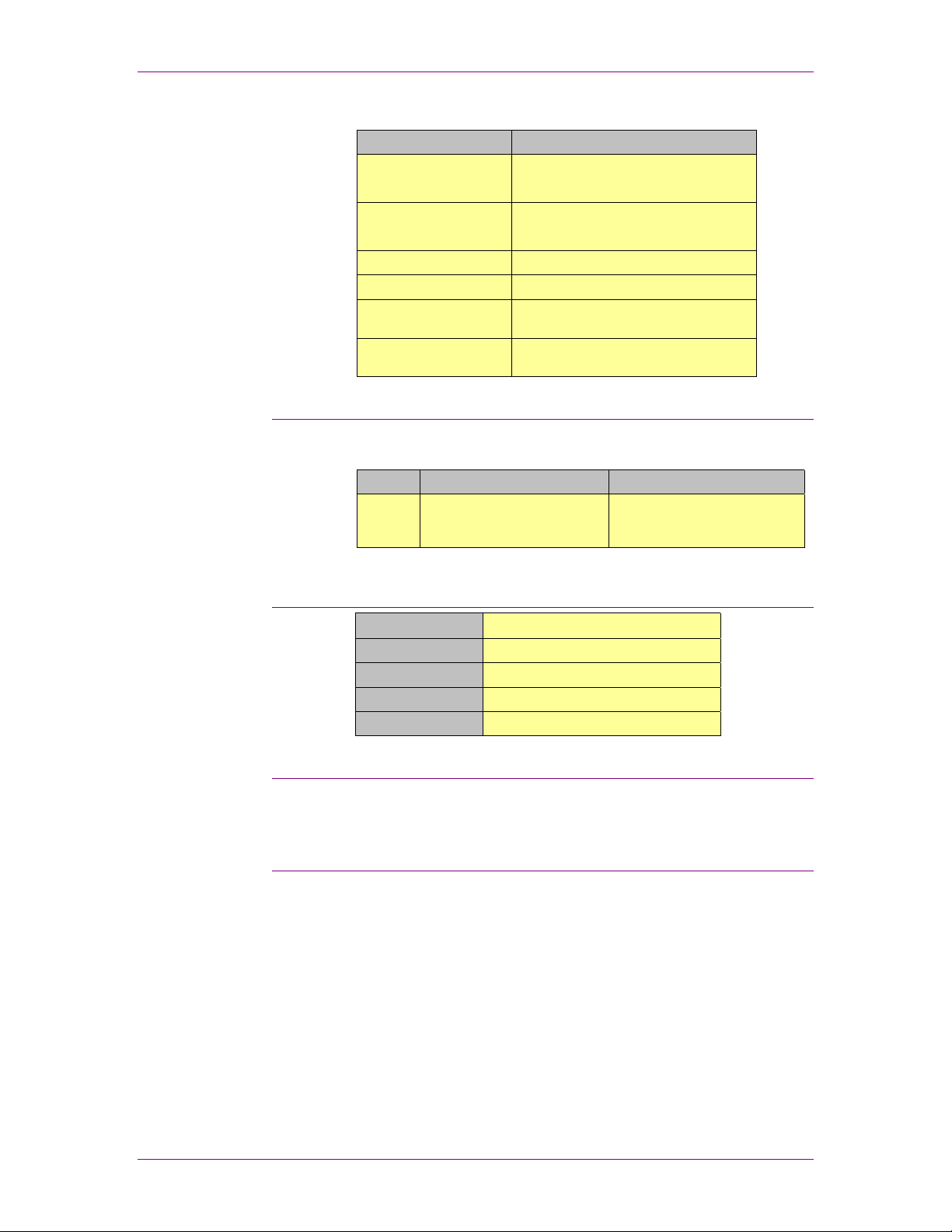
Electrical Requirements
Dimensions Finishing Transport Module
Width x Depth x Height
Shipping Dimensions
Width x Depth x Height
Weight
Shipping Weight
Operator Clearance
Service Clearance
Bypass Output Heights
35” x 28” x 44.6”
889 mm x 711.2 mm x 1133 mm
46” x 35.4” x 55”
1170 mm x 900 mm x 1400 mm
389 lbs (176 kg)
423 lbs (192 kg)
Minimum 24” (609.6mm) in front of the
device
Minimum 30” (763 mm) on all sides of
the device
34” (860 mm) and 40.2” (1021 mm)
Device North America Europe
FTM
Power
120 VAC (+/- 10%), 60 Hz, 7.5A 220 VAC (+/- 10%), 50 Hz, 3.5A
Environmental Requirements
Temperature
Humidity
Heat Emission
Sound Emission
Altitude
41 - 95° F (5 - 35°C)
10 – 85% (non-condensing)
1025 btu / hr
57 db
Minimum: -100 ft (-31 m)
Maximum: 40,000 ft (12, 192 m)
Estimated Installation Time
The Xerox CSE installs the FTM and the estimated installation
time is 4 hours.
Operating Supplies
There are no operating supplies for the FTM.
2-4
Page 13

Xerox Finishing Transport Module (FTM)
Customer Agreement
Devices
As a final step in the install planning you must complete the
Customer Agreement form.
Check off the modules that will be part of this install:
• Xerox Finisher Transport Module
Primary Customer Applications
Record the primary customer applications:
Special Considerations / Limitations
Record any special considerations and / or limitations identified
by Xerox and agreed to by the customer:
Upending / Stair Climbing
Upending and / or Stair Climbing Required and Reviewed:
Yes Not Required
I have reviewed the solution expectations and understand the specifications and
limitations for each of the modules that will be installed: (Signature and Date)
Customer
Xerox Sales Representative
Xerox Analyst Representative
Xerox Service Representative
2-5
Page 14

Xerox Finishing Transport Module (FTM)
2-6
Page 15
Xerox Document Stacker 5000 (DS5000)
3. Xerox Document Stacker 5000 (DS5000)
Product Overview
Performance Specifications
This section will provide you with the features and capabilities of
the Document Stacker.
The DS5000 High Capacity Stacker provides long periods of
unattended operation and facilitates the transport of accumulated
offset stacks of printed output for post processing. The stacks
are easily moved on one of two wheeled dollies supplied with
each stacker. The DS5000 is DFA compatible to meet full
productivity of the host printer. The stacker bypass capability
allows for transporting output to other in-line 3
rd
party finishing
devices. Up to two DS5000 stackers can be attached for
convenient unloading while running production.
Listed below are the Performance Specifications for the
Document Stacker 5000.
Stacking Specifications
Paper Size / Weight
Capacity
Output Height
Input Height
Paper Size: 7” x 10” (178 x 254 mm) – 12.6” x 18.5”
(320 x 470 mm)
Paper Weight: 16 lbs (60 gsm) – 110 lbs (200 gsm)
Top Tray: 250 sheets 20 lbs (75 gsm)
Stacker: 5,000 sheets 20 lbs (75 gsm)
Max Stack Height: 18.3” (465 mm)
40.2” (1021 mm)
40.2” (1021 mm)
Limitations
• A Finisher Transport Module is required for in-line
• The stacker performance is dependent on the printer module
connectivity to the printer.
decurler settings.
3-1
Page 16
Xerox Document Stacker 5000 (DS5000)
System Dependencies and Prerequisites
Listed below are the dependencies and prerequisites for
installing the DS5000 in-line with the Nuvera Digital Production
System.
• The Finisher Transport Module is required for in-line
connectivity to the printer.
Note: In case the floor at the customer site is very uneven, it is
recommended that the Nuvera IOT is installed and leveled with a
Caster Leveling Kit (kit number 498K07900).
Configuration Guide
The diagram below identifies the different printer and finishing
solutions that are currently supported.
Printer Configurations Finisher Configurations
SFM IOT FTM
SFM SFM IOT
SFM IOT INS
SFM SFM IOT
FTM
FTM
INS FTM
DS5000
DS5000
DB120D
FP II
SQFBM
BDFX
DS5000
DS5000
DS5000 DS5000 BDFX DS5000 DS5000 BDFXBCFX
DS5000
DS5000
DB120D
DS5000
DS5000
BCFX BDFXBCFX SQEDG
BDFX DS5000
BDFX
FP II
SQFBM
BDFX
SQEDG
BDFXBCFXDS5000 DS5000 SQEDG
DS5000
DS5000
DS5000
DS5000
DS5000
DS5000
DB120D
SQFBM
DS5000
DS5000
FP II
BDFX SQEDG
DS5000
BDFXBCFX SQEDGBDFXBCFX
BDFX SQEDG
3-2
Page 17

Xerox Document Stacker 5000 (DS5000)
Install Planning
Device Configurations
Space Requirements
This Install Planning guide will help you prepare for the
installation of the Document Stacker 5000.
The Document Stacker 5000 components are:
• Document Stacker 5000 with 2 paper dollies
The space requirements illustration provides machine footprint
as well as the overall operating and maintenance area.
In addition to the diagram below, there should be a minimum of
78 inches (1,981mm) clearance from the floor to the nearest
overhead obstruction.
30 inches
(763 mm)
Document
Stacker
(DS5000)
39.4 inches
30 inches
(763 mm)
(1000 mm)
69.4 inches
(1763 mm)
28.7 inches
(730 mm)
30 inches
(763 mm)
88.7 inches
(2253 mm)
Note: The space requirements diagram for the DS5000 is a
representation only and not drawn to scale.
3-3
Page 18
Xerox Document Stacker 5000 (DS5000)
Electrical Requirements
Dimensions Document Stacker
Width x Depth x Height
Shipping Dimensions
Width x Depth x Height
Weight
Shipping Weight
Operator Clearance
Service Clearance
39.4” x 28.7” x 47.2”
1000 mm x 730 mm x 1200 mm
47.2” x 31.5” x 55”
1200 mm x 800 mm x 1400 mm
429 lbs (195 kg) (includes 1 paper dolly)
661 lbs (300 kg)
Minimum 24” (609.6mm) in front of the
device
Minimum 30” (763 mm) on all sides of
the device
The recommended location of the electrical wall outlet is
mounted on a rear wall behind the DS5000.
Device North America Europe
DS5000
Power
107 – 127 VAC (+/- 10%), 60
Hz, 15A (single phase) GFI
Power Cord
220 – 240 VAC, (+/- 10%), 50
Hz, 13AmDPS/10A (line to
neutral) GFI Power Cord
Environmental Requirements
Temperature
Humidity
Heat Emission
Sound Emission
Altitude
50 - 90° F (10 - 32°C)
10 – 85%
1700 btu / hr
72 db
No restrictions.
Estimated Installation Time
The Xerox CSE installs the DS5000 and the estimated
installation time is 1.5 hour.
Operating Supplies
There are no operating supplies for the DS5000.
3-4
Page 19

Xerox Document Stacker 5000 (DS5000)
Customer Agreement
Devices
As a final step in the install planning you must complete the
Customer Agreement form.
Check off the modules that will be part of this install:
• Xerox Document Stacker 5000
Primary Customer Applications
Record the primary customer applications:
Special Considerations / Limitations
Record any special considerations and / or limitations identified
by Xerox and agreed to by the customer:
Upending / Stair Climbing
Upending and / or Stair Climbing Required and Reviewed:
Yes Not Required
I have reviewed the solution expectations and understand the specifications and
limitations for each of the modules that will be installed: (Signature and Date)
Customer
Xerox Sales Representative
Xerox Analyst Representative
Xerox Service Representative
3-5
Page 20

Xerox Document Stacker 5000 (DS5000)
3-6
Page 21

Xerox SquareFold BookletMaker (SQFBM) with optional Cover Insertion Module (CIM)
4. Xerox SquareFold BookletMaker (SQFBM) with
optional Cover Insertion Module (CIM)
This section will provide you with the features and capabilities of
the SquareFold BookletMaker and the optional Cover Insertion
Module.
Product Overview
The Xerox SquareFold Booklet Maker (SQFBM) is a unique
Xerox finishing product offering. The SQFBM has an additional
SquareFold Module that flattens the edge of a saddle-stapled
booklet to produce the look and feel of a perfect bound book.
SquareFold booklets stand upright on shelves for easy
identification and retrieval, and they stack compactly to minimize
shipping costs. For small size booklets sheets can be rotated in
the Finishing Transport module.
The SQFBM is also offered with and optional Cover Insertion
Module (CIM).
The SQFBM can top or corner stitch from 2 to 50 sheets, and it
can also be used in the fold only mode.
Performance Specifications
Listed below are the Performance Specifications for the Square
Fold Booklet Maker.
Stapling / Folding Specifications
Paper Size / Weight
Output Booklet Sizes
Stapling
Capacity
Input Height
CIM Specifications
Inserter Capacity
Paper Weight
500 sheets: 20 lbs bond (75 gsm) or equivalent.
Maximum Stack Height: 2.5” (63.5 mm)
Paper Weight: 20 lbs (75 gsm) –110 lbs index (200 gsm)
Paper Size: 8.5” x 11” (216 x 279 mm) – 12.25” x 18.2”
(311 x 462 mm)
Paper Weight: 16 lbs (60 gsm) – 110 lbs (200 gsm)
5.5” x 8.5” (140 x 216 mm) – 8.5” x 11” (216 x 279 mm)
Saddle stapling, 2 staple heads with 5,000 staples each
Fold only: 1 sheet 20 lbs (75 gsm)
Fold / Staple: 1 – 22 sheets 20 lbs (75 gsm)
Square Fold: 6 – 22 sheets 20 lbs (75 gsm)
34” (860 mm) and 40.2” (1021 mm)
Page 22

Xerox SquareFold BookletMaker (SQFBM) with optional Cover Insertion Module (CIM)
Limitations
• A Finisher Transport Module is required for in-line
connectivity to the printer.
• A Xerox Document Stacker 5000 is highly recommended for
stacking capability.
• When running greater than 20 lb (80 gsm) stock, the
operator must ensure that the total booklet thickness is less
than or equal to the thickness of a booklet with 22 sheets of
20 lb (80 gsm) stock.
• Staple position can vary up to 2 mm when being square
folded, especially on thicker booklets. The staple position is
not customer adjustable and a Service technician can adjust
them only slightly.
• Currently coated stock is not recommended.
System Dependencies and Prerequisites
Listed below are the dependencies and prerequisites for
installing the SQFBM in-line with the Nuvera Digital Production
System.
• The Finisher Transport Module is required for in-line
connectivity to the printer.
• A Xerox Document Stacker 5000 is highly recommended for
stacking capability.
• If there is a transition of an existing SQFBM to the Nuvera
Digital Production System, the SQFBM will require the Paper
Handling Enhancement kit (606N0028) to be installed. This
kit must be ordered by the CSE prior to the installation. Any
newly installed SQFBM prior to serial number H9E005508
will need this kit as well.
• If a Covers Insertion Module will be installed on the SQFBM,
a CIM Enablement Kit is required (product code MT0). This
applies to existing and new SQFBM.
Note: In case the floor at the customer site is very uneven, it is
recommended that the Nuvera IOT is installed and leveled with a
Caster Leveling Kit (kit number 498K07900).
4-2
Page 23

Xerox SquareFold BookletMaker (SQFBM) with optional Cover Insertion Module (CIM)
Configuration Guide
The diagram below identifies the different printer and finishing
solutions that are currently supported.
Printer Configurations Finisher Configurations
SFM IOT FTM
SFM SFM IOT
SFM IOT INS
SFM SFM IOT
FTM
FTM
INS FTM
DS5000
DS5000
DB120D
FP II
SQFBM
BDFX
DS5000
DS5000
DS5000 DS5000 BDFX DS5000 DS5000 BDFXBCFX
DS5000
DS5000
DB120D
DS5000
DS5000
BCFX BDFXBCFX SQEDG
BDFX DS5000
BDFX
FP II
SQFBM
BDFX
SQEDG
BDFXBCFXDS5000 DS5000 SQEDG
DS5000
DS5000
DS5000
DS5000
DS5000
DS5000
DB120D
SQFBM
DS5000
DS5000
FP II
BDFX SQEDG
DS5000
BDFXBCFX SQEDGBDFXBCFX
BDFX SQEDG
4-3
Page 24

Xerox SquareFold BookletMaker (SQFBM) with optional Cover Insertion Module (CIM)
Install Planning
This Install Planning guide will help you prepare for the
installation of the Square Fold Booklet Maker.
Device Configurations
The Square Fold Booklet Maker components are:
• Compiler / Stapler Module, Folder Module and Square Fold
Module with Conveyor
• Cover Insertion Module (CIM), optional
Space Requirements
The space requirements diagram provides machine footprint as
well as the overall operating and maintenance area.
In addition to the diagram below, there should be a minimum of
78 inches (1,981mm) clearance from the floor to the nearest
overhead obstruction.
Compiler /
Stapler Module
30 inches
(763 mm)
30 inches
(763 mm)
29 inches
(737 mm)
58 inches
(1470 mm)
35 inches
(890 mm)
Fold
Module
47 inches
(1194 mm)
170 inches
(4316 mm)
Square
Fold
Module
Conveyor
24 inches
(610 mm)
11 inches
(279 mm)
30 inches
(763 mm)
Note: The space requirements diagram for the SQFBM is a
representation only and not drawn to scale.
89 inches
(2263 mm)
4-4
Page 25

Xerox SquareFold BookletMaker (SQFBM) with optional Cover Insertion Module (CIM)
Dimensions Compiler/Stapler
Width x Depth x Height
Shipping Dimensions
Width x Depth x Height
Weight
Shipping Weight
Operator Clearance
Service Clearance
Module
69” (including the
Stacker) x 29” x 50”
1752 mm (including the
Stacker) x 740 mm x
1270 mm
78.8” x 35.4” x 59”
2000 mm x 900 mm x
1500 mm
705 lbs (320 kg) 569 lbs (258 kg) 132 lbs (60 kg) 125 lbs (56.75 kg)
855 lbs (388 kg) 694 lbs (315 kg) 187 lbs (85 kg) 154 lbs (70 kg)
Minimum 24”
(609.6mm) in front of
the device
Minimum 30” (763 mm)
on all sides of the
device
Fold Module Square Fold Module CIM (optional)
33” x 29” x 50”
838 mm x 740 mm x
1270 mm
63” x 35.4” x 59”
1600 mm x 900 mm x
1500 mm
Minimum 24”
(609.6mm) in front of
the device
Minimum 30” (763 mm)
on all sides of the
device
14” (49” including
Conveyor) x 29” x 50”
356 mm (1245 mm
including Conveyor) x
740 mm x 1270 mm
55” x 31.5” x 29.5”
1400 mm x 800 mm x
750 mm
Minimum 24”
(609.6mm) in front of
the device
Minimum 30” (763 mm)
on all sides of the
device
29” x 32” x 16”
720 mm x 794 mm x
385 mm
(CIM dimensions do
not affect floor space.)
33.8” x 34.6” x 33”
860 mm x 880 mm x
840 mm
Minimum 24”
(609.6mm) in front of
the device
Minimum 30” (763 mm)
on all sides of the
device
Electrical Requirements
The recommended location of the electrical wall outlet, mounted
on a rear wall is to be no more than 12 feet (3,65 m) away from
the right rear corner of the Compiler / Stapler module.
Device North America Europe
Compiler/Stapler/Folder
Power
Square Fold Module
Power
CIM Power
107 – 127VAC, 60 Hz,
6A (Single phase)
Power cord: 15 ft (4,572
mm)
105 – 127VAC, 60 Hz,
6A (Single phase)
Power cord: 15 ft (4,572
mm)
103 – 122VAC, 60 Hz,
1.87A
Power cord: 15 ft (4,572
mm)
Environmental Requirements
Environment Square Fold Booklet Maker Cover Insertion Module
Temperature
Humidity
Heat Emission
Sound Emission
Altitude
41 - 104° F (5 - 40°C) 60 - 85° F (15.5 – 29.4°C)
30 – 95% relative humidity 15 – 85% relative humidity
1198 btu / hr. (115V / 60Hz)
2150 btu / hr. (230V / 50Hz)
64.7 db TBD
No restrictions. Maximum: 6,000 ft (1,829m)
220 - 240VAC, 50 Hz,
3A (Line to Neutral)
Power cord: 15 ft (4,572
mm)
220 - 240VAC, 50 Hz,
3A (Line to Neutral)
Power cord: 15 ft (4,572
mm)
185 – 254VAC, 50 Hz,
1.4A
Power cord: 15 ft (4,572
mm)
648 btu / hr. (115V / 60Hz)
860 btu / hr. (230V / 50Hz)
4-5
Page 26

Xerox SquareFold BookletMaker (SQFBM) with optional Cover Insertion Module (CIM)
Estimated Installation Time
The Xerox CSE installs the SQFBM and the estimated
installation time is 4 – 6 hours.
Operating Supplies
Each SQFBM is delivered with 2 Cartons of Staple Cartridges.
Description Supply No. Unit Quantity / Unit
Staple Cartridge 8R12602 Carton
(3 Cartridges / Carton)
The Xerox Supplies Marketing Center is available for ordering
Xerox supplies, including paper and other throughput material.
You can reach the Xerox Supplies Marketing Center using the
following toll-free phone number:
• United States 1-800-822-2200
• Canada 1-800-668-0199
For Europe, please visit the Xerox web site and select your
country:
5, 0000 staples /
cartridge
http://www.xerox.com
4-6
Page 27

Xerox SquareFold BookletMaker (SQFBM) with optional Cover Insertion Module (CIM)
Unique Features Set
Listed below are diagrams of the various staple positions that the
SQFBM can produce.
AA A
4-7
Page 28

Xerox SquareFold BookletMaker (SQFBM) with optional Cover Insertion Module (CIM)
Customer Agreement
As a final step in the install planning you must complete the
Customer Agreement form.
Devices
Check off the modules that will be part of this install:
• Xerox SquareFold Booklet Maker
• Xerox Cover Insertion Module (optional)
Primary Customer Applications
Record the primary customer applications:
Special Considerations / Limitations
Record any special considerations and / or limitations identified
by Xerox and agreed to by the customer:
Upending / Stair Climbing
Upending and / or Stair Climbing Required and Reviewed:
Yes
I have reviewed the solution expectations and understand the specifications and
limitations for each of the modules that will be installed: (Signature and Date)
Customer
Xerox Sales Representative
Xerox Analyst Representative
Xerox Service Representative
4-8
Not Required
Page 29

C.P. Bourg BDFx Booklet Maker with optional Cover Feeder and Square Edge Module
5. C.P. Bourg BDFx Booklet Maker with optional Cover
Feeder and Square Edge Module
This section will provide you with the features and capabilities of
the Bourg Document Finisher and the optional Cover Feeder and
Square Edge Module.
Product Overview
The C.P. Bourg BDFx is a fully automated signature booklet
maker, which produces high quality saddle stitched booklets inline. The optional cover insertion module can feed preprinted
cover stock up to 250 gsm in sheet sizes up to 11” x 17” / A3.
The new Square Edge (SQEDG) Module option further expands
its capability by offering an optional square edge spine.
The BDFx is also offered with and optional Cover Feeder Module
(BCFx).
The BDFx can top or corner stitch from 2 to 50 sheets and it can
also be used in the fold only mode.
Performance Specifications
Listed below are the Performance Specifications for the C.P.
Bourg Document Finisher.
Media Latitude Device Specifications
Paper Type
Paper Size
Booklet Sizes
Stock Size Range
– Edge Stapling
Stitch Head
Sheet Capacity
(Stitching)
Input Height
BDFx / SQEDG
BCFx
BDFx
W/BCFx or HCS
BDFx / SQEDG
W/BCFx
BDFx / SQEDG
W/BCFx or HCS
One to four stitch heads (Hohner or Acme)
Saddle Stitching: 2 – 22 sheets
Edge / Top / Corner Stitching: 2 – 50 sheets
34” (860 mm) and 40.2” (1021 mm)
(∗) – Size may be limited by FTM or DS5000 pass-through capability.
Uncoated Body Stock: 16 lb. Bond to 110lb Index (60 gsm to 200 gsm)
Uncoated Cover Sheet: Uncoated 20lb to 10 pt cover (75 gsm to 300gsm)
Uncoated Cover Stock: 20 lb. Bond to 10 pt cover stock (80 gsm to 300 gsm)
5.5” x 8.5” to 12.6” x 18.5” (140mm X 216mm to 320mm X 470mm) (∗)
7” x 10” to 12.6” x 18.5” (179mm x 254mm to 320mm x 470mm) (∗)
5.5” x 4.25” to 12.6 x 9.3” (140mm x 108mm to 320mm x 236mm) (∗)
5” x 7” to 12.6” x 9.3” (127mm x 254mm to 320mm to 236mm) (∗)
5.5” x 8..25” to 11.625” x 14” (178mm x 203mm to 232mm x 356mm) (∗)
8” x 10” (SEF) to 10” x 11.72” (LEF) (203mm x 254mm to 254mm x 298mm) (∗)
5-1
Page 30

C.P. Bourg BDFx Booklet Maker with optional Cover Feeder and Square Edge Module
Limitations
• A Finisher Transport Module is required for in-line
connectivity to the printer.
• A Xerox Document Stacker 5000 is highly recommended for
stacking capability.
• A slight Cover Feeder feed mechanism adjustment may be
necessary when changing cover weights (lightweight stocks
may require a more precise adjustment).
• An adjustment to the BCFx is needed when transferring the
BCFx from an existing solution to a Nuvera Digital
Production System.
• For 11” x 17” / A3 simplex single fold only documents, paper
weight greater than 20 lb (80 gsm) are recommended.
• For 8.5” x 11” / A4 simplex single fold only documents, the
N-1 face up orientation is required.
• Currently coated stock is not recommended.
System Dependencies and Prerequisites
Listed below are the dependencies and prerequisites for
installing the BDFx in-line with the Nuvera Digital Production
System.
• The Finisher Transport Module is required for in-line
connectivity to the printer.
• A Xerox Document Stacker 5000 is highly recommended for
stacking capability.
• If there is a transition of an existing BDFx to a Nuvera Digital
Production System, an upgrade is needed (only if the BDFx
is equipped with a BCFx).
Note: In case the floor at the customer site is very uneven, it is
recommended that the Nuvera IOT is installed and leveled with a
Caster Leveling Kit (kit number 498K07900).
5-2
Page 31

C.P. Bourg BDFx Booklet Maker with optional Cover Feeder and Square Edge Module
Configuration Guide
The diagram below identifies the different printer and finishing
solutions that are currently supported.
Printer Configurations Finisher Configurations
SFM IOT FTM
SFM SFM IOT
SFM IOT INS
SFM SFM IOT
FTM
FTM
INS FTM
DS5000
DS5000
DB120D
FP II
SQFBM
BDFX
DS5000
DS5000
DS5000 DS5000 BDFX DS5000 DS5000 BDFXBCFX
DS5000
DS5000
DB120D
DS5000
DS5000
BCFX BDFXBCFX SQEDG
BDFX DS5000
BDFX
FP II
SQFBM
BDFX
SQEDG
BDFXBCFXDS5000 DS5000 SQEDG
DS5000
DS5000
DS5000
DS5000
DS5000
DS5000
DB120D
SQFBM
DS5000
DS5000
FP II
BDFX SQEDG
DS5000
BDFXBCFX SQEDGBDFXBCFX
BDFX SQEDG
5-3
Page 32

C.P. Bourg BDFx Booklet Maker with optional Cover Feeder and Square Edge Module
Install Planning
This Install Planning guide will help you prepare for the
installation of the Bourg Document Finisher X.
Device Configurations
The Bourg Document Finisher X components are:
• BDFx with Conveyor
• Bourg Cover Feeder X (BCFx), optional
• Square Edge Module (SQEDG), optional
Space Requirements
The space requirements illustration provides machine footprint
as well as the overall operating and maintenance area.
In addition to the diagram below, there should be a minimum of
82 inches (2.083 mm) clearance from the floor to the nearest
overhead obstruction.
35 inches
(889 mm)
C.P. Bourg Document
Finisher X
(BDFx)
35 inches
(889 mm)
62 inches
(1580 mm)
Note: If installing a BCFx with the BDFx, add dimensions from
table on next page. If installing a SQEDG module, replace the
Conveyor measurement with the SQEDG module dimensions
from the table on the next page.
24 inches
(613 mm)
Conveyor
35 inches
(889 mm)
35.5 inches
(900 mm)
94 inches
(2391 mm)
132.5 inches
(3369 mm)
Note: The space requirements diagram for the BDFx is a
representation only and not drawn to scale.
5-4
Page 33

C.P. Bourg BDFx Booklet Maker with optional Cover Feeder and Square Edge Module
Dimensions Bourg Document Finisher Square Edge Module
Width x Depth x Height
Shipping Dimensions
Width x Depth x Height
Weight
Shipping Weight
Operator Clearance
Service Clearance
97.5” x 24” x 71”
2480 mm x 739 mm x 1803
mm
77” x 30” x 73”
1950 mm x 750 mm x 1850
mm
992 lbs (450 kg) 198 lbs (90 kg) 291 lbs (132 kg)
1235 lbs (560 kg) 507 lbs (230 kg) 264 lbs (120 kg)
Minimum 24” (609.6mm) in
front of the device
Minimum 35” on all sides of
the device
28” x 29.5” x 49”
707 mm x 745 mm x 1242
mm
47.2” x 35.8” x 63”
1200 mm x 910 mm x 1600
mm
Minimum 24” (609.6mm) in
front of the device
Minimum 35” on all sides of
the device
(optional)
Electrical Requirements
Device North America Europe
BDF-X Power
BCF-X Power
SQEDG Power
120 VAC (+/- 10%), 60 Hz, 10A 230 VAC (+/- 10%), 50 Hz, 7A
120 VAC (+/- 10%), 60 Hz, 5A 230 VAC (+/- 10%), 50 Hz, 3A
120 VAC (+/- 10%), 60 Hz, 5A 230 VAC (+/- 10%), 50 Hz, 3A
Bourg Cover Feeder
(optional)
26.75” x 27” x 52”
680 mm x 687 mm x 1242
mm
51” x 31.5” x 59”
1300 mm x 800 mm x 1500
mm
Minimum 24” (609.6mm) in
front of the device
Minimum 35” on all sides of
the device
Environmental Requirements
Environment BDFx / BCFx / SQEDG
Temperature
Humidity
Heat
Emission
Sound
Emission
Altitude
41 - 95° F (5 - 35°C)
40 - 85%
BDFx: 2560 btu / hr
BCFx: 1590 btu / hr
SQEDG: 2400 btu / hr
72 db
-100 ft. (-31m) to 40,000 ft. (12,192m)
Estimated Installation Time
C.P. Bourg installs the BDFx and the estimated installation time
is 4 – 8 hours.
5-5
Page 34

C.P. Bourg BDFx Booklet Maker with optional Cover Feeder and Square Edge Module
Operating Supplies
Each Bourg Document Finisher is delivered with 2 stitch heads.
The machine can be upgraded with 1 or 2 additional stitch
heads.
Supply No. Description. Quantity / Unit
9158017 Wire Cassette (Acme Stitch Heads) 50, 0000 stitches / cassette
9158018 Wire Spool (Hohner Stitch Heads) 50, 0000 stitches / spool
You can reach C.P. Bourg Customer Service using the following
phone number:
• United States and Canada: 1-508-998-2171
For Europe, please visit the C.P. Bourg web site and select your
region:
http://www.cpbourg.com
5-6
Page 35

C.P. Bourg BDFx Booklet Maker with optional Cover Feeder and Square Edge Module
Unique Features Set
Listed below are diagrams of the various stitch positions that the
BDF-X can produce.
Note: The BDFx is delivered with 2 stitch heads. A third and forth
stitch head must be ordered and installed to enable the 3 and
four stitch options shown in the above diagram.
5-7
Page 36

C.P. Bourg BDFx Booklet Maker with optional Cover Feeder and Square Edge Module
Customer Agreement
As a final step in the install planning you must complete the
Customer Agreement form.
Devices
Check off the modules that will be part of this install:
• C.P. Bourg Document Finisher
• C.P. Bourg Cover Feeder (optional)
• C.P. Bourg Square Edge Module (optional)
Primary Customer Applications
Record the primary customer applications:
Special Considerations / Limitations
Record any special considerations and / or limitations identified
by Xerox and agreed to by the customer:
Upending / Stair Climbing
Upending and / or Stair Climbing Required and Reviewed:
Yes
I have reviewed the solution expectations and understand the specifications and
limitations for each of the modules that will be installed: (Signature and Date)
Customer
Xerox Sales Representative
Xerox Analyst Representative
Xerox Service Representative
5-8
Not Required
Page 37

GBC Fusion Punch II with Offset Stacker (FP II)
6. GBC Fusion Punch II with Offset Stacker (FP II)
This section will provide you with the features and capabilities of
the Fusion Punch II and Offset Stacker.
Product Overview
The GBC Fusion Punch II provides in-line printer punching
combining printing and punching into one step. Single sheets are
punched and emerge ready to be finished into lay flat
documents. These types of documents are typically bound with
coil, wire or plastic comb binding and will lay flat when opened.
The Fusion Punch II can punch the long edge of an 8.5” x 11 /A4
or the short edge of an 11” x 17” / (279 mm x 432mm) sheet. A
wide variety of hole-punch patterns are available. The die sets
are lightweight, do not require setup adjustment time when
changed and can be easily replaced by the operator.
The attached stacker can offset stack up to 2,500 sheets
preparing each document for immediate binding.
Performance Specifications
Listed below are the Performance Specifications for the Fusion
Punch II.
Punch / Stacker Specifications
Paper Size / Weight
Stacker Capacity
Input Heights
Limitations
• A Finisher Transport Module is required for in-line
connectivity to the printer.
• A Xerox Document Stacker 5000 is recommended for
stacking paper weights greater than 203 gsm and sizes
smaller than 8.5” x 11” (216 x 279 mm) or larger than 11” x
17” (279 x 432 mm).
• Punching is limited to 7” x 10”size up to 8.5” x 11” / A4, long
edge and 11” x 17” / A3 short edge (including tabs).
• The validated configuration is limited to the Fusion Punch II
with a single offset stacker.
Paper Size: 7” x 10” (178 x 254 mm) – 11” x 17” (279 x
432 mm)
Paper Weight: 16 lbs (60 gsm) – 90 lbs index (200 gsm)
Stacker 2,500 sheets
34” (860 mm) and 40.2” (1021 mm)
• Coated stocks may mark; therefore, specific stocks should
be tested before running.
Page 38

GBC Fusion Punch II with Offset Stacker (FP II)
System Dependencies and Prerequisites
Listed below are the dependencies and prerequisites for
installing the FP II in-line with the Nuvera Digital Production
System.
• The Finisher Transport Module is required for in-line
connectivity to the printer.
• A Xerox Document Stacker 5000 is recommended for
stacking paper weights greater than 203 gsm and sizes
smaller than 8.5” x 11” (216 x 279 mm) or larger than 11” x
17” (279 x 432 mm).
• If there is a transition of an existing FP II to a Nuvera Digital
Production System, the FP II will require an upgrade.
Note: In case the floor at the customer site is very uneven, it is
recommended that the Nuvera IOT is installed and leveled with a
Caster Leveling Kit (kit number 498K07900).
Configuration Guide
The diagram below identifies the different printer and finishing
solutions that are currently supported.
Printer Configurations Finisher Configurations
SFM IOT FTM
SFM SFM IOT
SFM IOT INS
SFM SFM IOT
FTM
FTM
INS FTM
DS5000
DB120D
FP II
SQFBM
BDFX
DS5000
DS5000
BDFX DS5000
BDFX
DS5000
DS5000
DS5000
DB120D
DS5000
DS5000
SQFBM
BDFX
BCFX BDFXBCFX SQEDG
SQEDG
FP II
DS5000
DS5000
DS5000
DS5000
DS5000
DS5000
DB120D
FP II
SQFBM
DS5000
BDFX SQEDG
BDFXBCFX SQEDGBDFXBCFX
DS5000 DS5000 BDFX DS5000 DS5000 BDFXBCFX
BDFXBCFXDS5000 DS5000 SQEDG
DS5000
6-2
DS5000
BDFX SQEDG
Page 39

GBC Fusion Punch II with Offset Stacker (FP II)
Install Planning
This Install Planning guide will help you prepare for the
installation of the GBC Fusion Punch II.
Device Configurations
The GBC Fusion Punch II components are:
• GBC Fusion Punch II with Stacker
Note: The GBC Fusion Punch II with Bypass and dual Stacker is
not currently supported with the Nuvera Digital Production
System.
Space Requirements
The space requirements illustration provides machine footprint
as well as the overall operating and maintenance area.
In addition to the diagram below, there should be a minimum of
78 inches (1,981mm) clearance from the floor to the nearest
overhead obstruction.
36 inches
(914 mm)
GBC Fusion Punch II
(with Offset Stacker)
54 inches
36 inches
(914 mm)
(1372 mm)
105 inches
(2668 mm)
32 inches
(813 mm)
27 inches
(686 mm)
24 inches
(610 mm)
104 inches
(2641 mm)
Note: The space requirements diagram for the FP II is a
representation only and not drawn to scale.
6-3
Page 40

GBC Fusion Punch II with Offset Stacker (FP II)
Dimensions Fusion Punch Stacker
Width x Depth x Height
Shipping Dimensions
Width x Depth x Height
Weight
Shipping Weight
Operator Clearance
Service Clearance
Electrical Requirements
Device North America Europe
Punch Power
Stacker Power
54” x 32” x 46”
(1372 mm x 813 mm x 1168 mm)
60 5/8” x 41” x 57 1/4”
(1535 mm x 1041 mm x 1452 mm)
620 lbs (281 kg) 270 lbs (123 kg)
920 lbs (417 kg) 470 lbs (213 kg)
Minimum 24” (609.6mm) in front of the
device
Minimum 36” (914 mm) on all sides of
the device
115V, 60 Hz, 4.7A 230V, 50 Hz, 6.8A
115V, 60 Hz, 1.0A 230V, 50 Hz, 0.25A
27” x 32” x 16”
(720mm x 794mm x 385mm)
39” x 35 3/4” x 52 1/2”
(990 mm x 905 mm x 1333 mm
Minimum 24” (609.6mm) in front of the
device
Minimum 36” (914 mm) on all sides of
the device
Environmental Requirements
Temperature
Humidity
Heat Emission
(Punch & Stacker)
Sound Emission
Altitude
41 - 104° F (5 - 40°C)
30 – 95% (non-condensing)
1198 btu / hr. (115V / 60Hz)
2150 btu / hr. (230V / 50Hz)
64.7 db (Idling)
73.7 db (Running both Punch/Stacker)
Maximum: 3280 ft. (1000m)
Estimated Installation Time
GBC personnel install the Fusion Punch II and the estimated
installation time is 4 - 8 hours.
6-4
Page 41

GBC Fusion Punch II with Offset Stacker (FP II)
Operating Supplies
The Fusion Punch II is not delivered with a specific die set. A die
set must be ordered when ordering the machine.
Supply No. Description Quantity
0131000000 PB Plastic Bind (Plastic Coil) 1 set
0131060000 PB Plastic Bind Oversized (Plastic Coil) 1 set
0131020000 W2 Wire Rectangle - 2 holes/inch (Twin Loop) 1 set
0131010000 W3 Wire Square - 3 holes/inch (Twin Loop) 1 set
0131140000 W2 Wire Round - 2 holes/inch (Twin Loop) 1 set
0131050000 C4 Coil Round - 4 holes/inch (Color Coil) 1 set
0131190000 C4 Coil Oval - 4 holes/inch (Color Coil) 1 set
0131030000 3-5-7 Ring Binder (Looseleaf) 1 set
You can reach GBC Customer Service using the following phone
number:
• United States 1-847-272-3700
For Canada and Europe, please visit the GBC web site and
select your region:
http://www.GBC.com
6-5
Page 42

GBC Fusion Punch II with Offset Stacker (FP II)
Unique Features Set
The following are diagrams of the die set configurations, which
are available for the Fusion Punch ll. These pictures do not
reflect sheet size limitations, rather provide a visual for the die
set configuration. Refer to specifications for sheet size
capabilities.
For Plastic Coil Binding choose from:
1 #0130000000 21
PB Plastic Bind Hole Size: .313” L x .125” W (7.95 x 3.175 mm) Center to Center Hole Spacing: .5625” (14.29 mm)
1 #0131060000 21
PB Plastic Bind Oversized Hole Size: .313” L x .188” W (7.95 x 4.77 mm) Center to Center Hole Spacing: .5625” (14.29 mm)
For Twin Loop Binding choose from:
1 #0131020000 23
W2 Wire Rectangle - 2 holes/in. (25.4 mm) Hole Size: .250” L x .214” W (7.95 x 5.44 mm) Center to Center Hole Spacing: .5” (12.7 mm)
1 #0131140000 23
W2 Wire Round - 2 holes/in. (25.4 mm) Hole Size: .250” Diameter (6.35 mm) Center to Center Hole Spacing: .5” (12.7 mm)
1 #0131010000 34
W3 Wire Square - 3 holes/in. (25.4 mm) Hole Size: .156” L x .156” W (3.96 x 3.96 mm) Center to Center Hole Spacing: .333” (8.46 mm)
For Color Coil Binding choose from:
1 #0131050000 47
C4 Coil Round - 4 holes/in. (25.4 mm) Hole Size: .172” Diameter (4.37 mm) Center to Center Hole Spacing: .2475” (6.29 mm)
1 #0131190000 47
C4 Coil Oval - 4 holes/in. (25.4 mm) Hole Size: .158” L x 197” (4 x 5 mm) Center to Center Hole Spacing: .2475” (6.29 mm)
For Looseleaf Binding:
1 #0131030000 7
3-5-7 Ring Binder – U.S. (Standard Looseleaf Pattern) Hole Size: .312 Diameter” (7.92mm)
6-6
Page 43

GBC Fusion Punch II with Offset Stacker (FP II)
Customer Agreement
As a final step in the install planning you must complete the
Customer Agreement form.
Devices
Check off the modules that will be part of this install:
• GBC Fusion Punch II with Offset Stacker
Primary Customer Applications
Record the primary customer applications:
Special Considerations / Limitations
Record any special considerations and / or limitations identified
by Xerox and agreed to by the customer:
Upending / Stair Climbing
Upending and / or Stair Climbing Required and Reviewed:
Yes Not Required
I have reviewed the solution expectations and understand the specifications and
limitations for each of the modules that will be installed: (Signature and Date)
Customer
Xerox Sales Representative
Xerox Analyst Representative
Xerox Service Representative
6-7
Page 44

GBC Fusion Punch II with Offset Stacker (FP II)
6-8
Page 45

Xerox Document Binder 120-D (DB120-D)
7. Xerox Document Binder 120-D (DB120-D)
Product Overview
This section will provide you with the features and capabilities of
the Document Binder 120-D.
The Document Binder DB120-D uses a unique thermal binding
technology combined with pre-formed covers to create a high
quality professionally bound document. The DB120-D binds 8.5”
x 11” / A4 documents up to 120 pages in a variety of attractive
covers.
You can custom order imprinted covers with your logo or a
particular design. The pre-formed cover wraps around the
internal pages to produce a perfect bound document with a
commercial look and feel. The document pages fit neatly and
uniformly into the bind for the perfect bound look with no
trimming needed.
The usability improves due to the hinged spine scoring which
allows pages to lie flat when opened. The book binding adhesive
is reinforced with a special mesh/cloth material to ensure a
strong, consistent bind with no mess or oozing.
Performance Specifications
Listed below are the Performance Specifications for the
Document Binder 120-D.
Binding Specifications
Paper Sizes
Cover Sizes
Spine Width / Approx. # of
sheets
(Based on 20 lbs (75 gsm)
Tray Capacity
Warm-up Time
Input Height
Paper Size: 8.5” x 11” (216 x 279 mm)
Paper Weight: 20 lbs (75 gsm) – 32 lbs index (120 gsm)
bond and flush cut tabs.
Weights above 32 lbs. (120 gsm) should be used only
as covers, dividers or inserts.
1/16” (1.5 mm) / 3 – 15 sheets (∗)
1/8” (3 mm) / 16 – 30 sheets
1/4" (6 mm) / 31 – 60 sheets
3/8” (9 mm) / 61 – 90 sheets
1/2" (13 mm) / 91 – 120 sheets
(∗) 1 – 15 sheets in walk-up mode.
Input Tray: Pre-loaded cassettes containing 150 covers
Output Tray: 20 – 100 finished sets depending on spine
width
Approx. 2 minutes
34” (860 mm) and 40.2” (1021 mm)
7-1
Page 46

Xerox Document Binder 120-D (DB120-D)
Limitations
System Dependencies and Prerequisites
• A Finisher Transport Module is required for in-line
connectivity to the printer.
• A Xerox Document Stacker 5000 is highly recommended for
stacking capability.
• Currently coated stock is not recommended.
Listed below are the dependencies and prerequisites for
installing the DB120-D in-line with the Nuvera Digital Production
System.
• The Finisher Transport Module is required for in-line
connectivity to the printer.
• A Xerox Document Stacker 5000 is highly recommended for
stacking capability.
• If the DB120-D is installed in-line with another Finishing
Device (such as a DS5000), the 1021 Height Kit must be
installed (unit is shipped with 860 Height Kit installed).
• If there is a transition of an existing (stand alone or from a
different printer) DB120-D to a Nuvera Digital Production
System, the DB120-D will require an upgrade.
Note: In case the floor at the customer site is very uneven, it is
recommended that the Nuvera IOT is installed and leveled with a
Caster Leveling Kit (kit number 498K07900).
7-2
Page 47

Xerox Document Binder 120-D (DB120-D)
Configuration Guide
The diagram below identifies the different printer and finishing
solutions that are currently supported.
Printer Configurations Finisher Configurations
SFM IOT FTM
SFM SFM IOT
SFM IOT INS
SFM SFM IOT
FTM
FTM
INS FTM
DS5000
DS5000
DB120D
FP II
SQFBM
BDFX
DS5000
DS5000
DS5000 DS5000 BDFX DS5000 DS5000 BDFXBCFX
DS5000
DS5000
DB120D
DS5000
DS5000
BCFX BDFXBCFX SQEDG
BDFX DS5000
BDFX
FP II
SQFBM
BDFX
SQEDG
BDFXBCFXDS5000 DS5000 SQEDG
DS5000
DS5000
DS5000
DS5000
DS5000
DS5000
DB120D
SQFBM
DS5000
DS5000
FP II
BDFX SQEDG
DS5000
BDFXBCFX SQEDGBDFXBCFX
BDFX SQEDG
7-3
Page 48

Xerox Document Binder 120-D (DB120-D)
Install Planning
Device Configurations
Space Requirements
This Install Planning guide will help you prepare for the
installation of the DB 120-D.
The Document Binder 120-D components are:
• Document Binder 120-D
The space requirements illustration provides machine footprint
as well as the overall operating and maintenance area.
In addition to the diagram below, there should be a minimum of
78 inches (1,981mm) clearance from the floor to the nearest
overhead obstruction.
17 inches
(432 mm)
Document Binder 120-D
(DB120-D)
56 inches
(1422 mm)
30 inches
(763 mm)
73 inches
(1854 mm)
24 inches
(610 mm)
17 inches
(432 mm)
71 inches
(1805 mm)
Note: The space requirements diagram for the DB 120-D is a
representation only and not drawn to scale.
7-4
Page 49

Xerox Document Binder 120-D (DB120-D)
Electrical Requirements
Dimensions Document Binder 120-D
Width x Depth x Height
Shipping Dimensions
Width x Depth x Height
Weight
Shipping Weight
Operator Clearance
Service Clearance
56” x 24” x 50 1/2”
1422.4mm x 609.6mm x 1282.7mm
66.5” x 31” x 53.25”
1689.1 mm x 787.4 mm x 1352.55 mm
462 lbs (210 kg)
542 lbs (246.4 kg)
Minimum 24” (609.6mm) in front of the device
Minimum 30” (763 mm) in front, 17” (432 mm)
behind and to the right of the device
The recommended location of the electrical wall outlet, mounted
on a rear wall is to be no more than 6 feet (1,829mm) away from
the rear center of the Document Binder 120-D.
Device North America Europe
Power
115VAC, 60 Hz, 7A (∗)
Power cord: 6 - 8 ft (1,829
– 2,438 mm)
220VAC, 50 Hz, 3.5A
Power cord: 6 - 8 ft (1,829 –
2,438 mm)
(∗) – Dedicated outlet required.
Environmental Requirements
Temperature
Humidity
Heat Emission
Sound Emission
Altitude
50 - 90° F (10 - 32°C)
10 – 85% (non-condensing)
108 btu / hr. (Energy Saver mode)
809 btu / hr. (Standby mode)
1106 btu / hr. (Operating mode)
Standby: 46 dB
4 sheets binding: 68 dB
30 sheets binding: 66 dB
100 sheets binding: 66 dB
0 – 13,000 ft. (0 – 4,000 m)
Estimated Installation Time
CoverBind personnel install the DB120-D and the estimated
installation time is 2 hours.
7-5
Page 50

Xerox Document Binder 120-D (DB120-D)
Operating Supplies
Each DB120-D is delivered with a sampler pack of standard
binder covers.
There are several styles of covers available:
• Classic covers – non glare, clear plastic front cover with
satin UV-coated spine and back cover. Available in:
• White, Black, Burgundy, Dark Blue, Royal Blue, Red,
Green and Teal
• Impression covers - non-glare, clear plastic front cover with
80 lb uncoated linen spine and back cover. Available in:
• White, Black, Red, Gray, Blue, Metallic Blue, Metallic
Copper, Metallic Silver and Marbled Blue.
• Custom covers – wrap around covers with customized color
printing, foil stamping or die cutting. *
* - For custom covers, contact your Xerox sales representative
(or visit
http://www.xerox.com
, and select Supplies) for more
information.
Covers range in spine width, from 1/16” – 1/2", and there are 450
covers / carton.
The Xerox Supplies Marketing Center is available for ordering
Xerox supplies, including paper and other throughput material.
You can reach the Xerox Supplies Marketing Center using the
following toll-free phone number:
• United States 1-800-822-2200
• Canada 1-800-668-0199
For Europe, please visit the Xerox web site and select your
country:
http://www.xerox.com
7-6
Page 51

Xerox Document Binder 120-D (DB120-D)
Customer Agreement
Devices
As a final step in the install planning you must complete the
Customer Agreement form.
Check off the modules that will be part of this install:
• Xerox Document Binder 120-D
Primary Customer Applications
Record the primary customer applications:
Special Considerations / Limitations
Record any special considerations and / or limitations identified
by Xerox and agreed to by the customer:
Upending / Stair Climbing
Upending and / or Stair Climbing Required and Reviewed:
Yes Not Required
I have reviewed the solution expectations and understand the specifications and
limitations for each of the modules that will be installed: (Signature and Date)
Customer
Xerox Sales Representative
Xerox Analyst Representative
Xerox Service Representative
7-7
Page 52

Xerox Document Binder 120-D (DB120-D)
7-8
Page 53

Standard Horizon Perfect Binder BQ-270x (BQ-270x)
8. Standard Horizon Perfect Binder BQ-270x (BQ-270x)
This section will provide you with the features and capabilities of
the Perfect Binder BQ-270x.
Product Overview
The BQ-270x features high-quality production perfect binding
with fully automated operation and push-button simplicity. The
BQ-270x single-clamp binder is designed for single-person
production of up to 500 books per hour, and requires minimal
operator training.
Standard features include an intelligent touch-screen control
console, newly-developed adhesive application and side-gluing
system, automatic air-suction cover feeding with in-line scoring,
job programming, and same-location loading and unloading for
easier single-person operation.
The BQ-270x, with its state-of-the-art design, compact
configuration, and full automation, is positioned to meet the
demands of the short-run, print-on-demand book market. The
BQ-270x includes: DV-270 Conveyor / Stacker and the SI-270
Digital Caliper. An off-line trimmer is required to complete the
application.
Performance Specifications
Listed below are the Performance Specifications for the
Standard Horizon Perfect Binder BQ-270x.
Binding Specifications
Book Sizes
Cover
Maximum Milling Depth
Warm-up Time
Minimum Book Size: 5.4” x 4.2” (137 x 106 mm)
Maximum Book Size: 12.6” x 12.6” (320 x 320 mm)
Book Thickness: 0.04” x 2” (1 x 50 mm)
Minimum Size: 5.4” x 9.1” (137 x 231 mm) ∗
Maximum Size: 12.6” x 26” (320 x 660 mm) ∗
Weight: (82 – 302 gsm)
Maximum Pile Height: 3.1” (78 mm)
(∗) – Top to bottom by fore-edge.
0.12” (3 mm)
Approx. 40 minutes
System Dependencies and Prerequisites
Listed below are the dependencies and prerequisites for
installing the BQ-270x.
• There are no known dependencies or prerequisites at
this time.
8-1
Page 54

Standard Horizon Perfect Binder BQ-270x (BQ-270x)
Install Planning
This Install Planning guide will help you prepare for the
installation of the Standard Horizon Perfect Binder BQ-270x.
Device Configurations
The BQ-270x components are:
• Perfect Binder BQ-270x, including DV-270 Conveyor /
Stacker and the SI-270 Digital Caliper
Space Requirements
The space requirements illustration provides machine footprint
as well as the overall operating and maintenance area.
36 inches
(910 mm)
106.8 inches
(2712 mm)
34 inches
(860 mm)
101.5 inches
(2575 mm)
68 inches
(1715 mm)
36 inches
(910 mm)
DV-270
Conveyor
36 inches
(910 mm)
Standard Horizon
Perfect Binder BQ-270x
(BQ-270x)
21.3 inches
(540 mm)
173.5 inches
(4395 mm)
36 inches
(910 mm)
199.5 inches
(5012 mm)
Note: The space requirements diagram for the BQ-270x is a
representation only and not drawn to scale.
8-2
Page 55

Standard Horizon Perfect Binder BQ-270x (BQ-270x)
Dimensions Perfect Binder BQ-270x Conveyor (DV-270)
Width x Depth x Height
Shipping Dimensions
Width x Depth x Height
Weight
Shipping Weight
Operator Clearance
Service Clearance
Electrical Requirements
Device North America Europe
BQ-270x
Environmental Requirements
Environment Perfect Binder BQ-270x
Temperature
Humidity
Heat Emission
Sound Emission
Altitude
90.6” x 35.9” x 49.2”
2712 mm x 910 mm x 1250 mm
144” x 48” x 60”
3660 mm x 1219 mm x 1524 mm
1,984.5 lbs (900 kg) 240 lbs (108.9 kg)
2,581 lbs (1,161 kg) 279 lbs (126.5 kg)
Minimum 36 ” (910 mm) in front of
the device
Minimum 36” (910 mm) on all
sides of the device
208VAC, 20A, 3-phase 220VAC, 60 Hz, 20A
65° F (18.3°C)
75 % relative humidity
9898 btu / hr. (208V/ 60 Hz)
67.2 db
N/A
67.6” x 18.9” x 24”
1715 mm x480 mm x 610 mm
50” x 42” x 40”
1270 mm x 1067 mm x 1016 mm
Minimum 36 ” (910 mm) in front of
the device
Minimum 36 ” (910 mm) in front of
and behind the device
Estimated Installation Time
Standard Finishing Systems / Horizon will ship the BQ-270x
directly to the customer. A Standard Finishing Systems
representative will do the equipment installation and the
estimated installation time is 4 hours
.
Operating Supplies
The BQ-270x is not delivered with any supplies.
Supply No. Description Quantity / Unit
HM-220 Hot-melt adhesive 44 lbs (20 kg) / carton
You can reach Standard Horizon Customer Service using the
following phone number:
• United States 1-877-404-4460
For Canada and Europe, please visit the Standard Horizon web
site and select your region:
http://www.sdmc.com
8-3
Page 56

Standard Horizon Perfect Binder BQ-270x (BQ-270x)
Customer Agreement
As a final step in the install planning you must complete the
Customer Agreement form.
Devices
Check off the modules that will be part of this install:
• Standard Horizon Perfect Binder BQ-270x
Primary Customer Applications
Record the primary customer applications:
Special Considerations / Limitations
Record any special considerations and / or limitations identified
by Xerox and agreed to by the customer:
Upending / Stair Climbing
Upending and / or Stair Climbing Required and Reviewed:
Yes Not Required
I have reviewed the solution expectations and understand the specifications and
limitations for each of the modules that will be installed: (Signature and Date)
Customer
Xerox Sales Representative
Xerox Analyst Representative
Xerox Service Representative
8-4
Page 57

Powis Parker Fastback Model 15xs
9. Powis Parker Fastback Model 15xs
Product Overview
This section will provide you with the features and capabilities of
the Fastback Model 15xs.
The Fastback® Model 15xs is a high production desktop
document binding machine which binds from 3 to 350 sheets
quickly, easily, and economically.
Documents can be edited in seconds. Other primary features
include: on demand perfect binding capabilities, teflon coated
platens that simplify maintenance and cleaning, and a document
cooling rack that can be mounted on the binder itself, or can
stand alone.
The binder strip uses a super tough thermoplastic adhesive that
will not become brittle with age, Fastback® documents stay
bound for years.
Performance Specifications
Listed below are the Performance Specifications for the
Fastback Model 15xs.
Binding Specifications
Paper Size
Output Booklet Sizes
Binding Time
Strip Widths
Document Thickness
Strip Lengths
Warm-up Time
Paper Size: from 5” – 14 7/8” (311 x 462 mm)
5.5” x 8.5” (140 x 216 mm) – 8.5” x 11” (127 - 370 mm)
15 – 25 seconds (depending on book thickness)
Narrow: 3 – 150 sheets approx.
Medium: 150 – 250 sheets approx.
Wide: 250 –350 sheets approx.
1.5” (38.1 mm)
8 ½”, 11”, 14”, 14 7/8”, A4 and A5
9 minutes
Limitations
• Coated and glossy stocks are not supported.
System Dependencies and Prerequisites
Listed below are the dependencies and prerequisites for
installing the Fastback® Model 15xs.
• Table / stand designed to hold 55 lbs (24.9 kg).
9-1
Page 58

Powis Parker Fastback Model 15xs
Install Planning
Device Configurations
Space Requirements
This Install Planning portion will help you prepare for the
installation of the Fastback® Model 15xs.
The Fastback® Model 15xs components are:
• Fastback Model 15xs, including cooling rack
The space requirements diagram provides machine footprint as
well as the overall operating and maintenance area.
Dimensions Fastback Model 15xs
Width x Depth x Height
Shipping Dimensions
Width x Depth x Height
Weight
Shipping Weight
25” x 22” x 9.5”
635 mm x 559 mm x 241 mm
37” x 29” x 14”
940 mm x 736 mm x 356 mm
55 lbs (24.9 kg)
75 lbs (34 kg)
Electrical Requirements
Device North America Europe
Fastback Model 15xs
120VAC, 60 Hz, 7A 220VAC, 50 Hz, 3.5A
Environmental Requirements
Environment Fastback Model 15xs
700 btu / hr.
Heat Emission
Estimated Installation Time
A local Powis Parker dealer will deliver and install the equipment.
The estimated installation time is 1 hour.
9-2
Page 59

Powis Parker Fastback Model 15xs
Operating Supplies
Each Fastback Model 15xs is delivered with a pack of 100
narrow strips in assorted colors.
To order Powis Parker supplies, please visit the Powis Parker
web site and locate a local dealer:
http://www.powis.com/dealers/dealers.asp
9-3
Page 60

Powis Parker Fastback Model 15xs
Customer Agreement
Devices
As a final step in the install planning you must complete the
Customer Agreement form.
Check off the modules that will be part of this install:
• Powis Parker Fastback® Model 15xs
Primary Customer Applications
Record the primary customer applications:
Special Considerations / Limitations
Record any special considerations and / or limitations identified
by Xerox and agreed to by the customer:
Upending / Stair Climbing
Upending and / or Stair Climbing Required and Reviewed:
Yes Not Required
I have reviewed the solution expectations and understand the specifications and
limitations for each of the modules that will be installed: (Signature and Date)
Customer
Xerox Sales Representative
Xerox Analyst Representative
Xerox Service Representative
9-4
Page 61

Powis Parker Fastback Model 15xs
9-5
Page 62

 Loading...