

Page 1

Xerox DocuPrint N2025/N2825
CAUTION
These components are susceptible
to electrostatic discharge. Observe
all ESD procedures to avoid
damage.
Network Laser Printer Service Manual
XEROX
721P52440
February 2000
This Service Manual contains information
that applies to the DocuPrint N2025/N2825
Laser Printer.
Page 2

Copyright
This Service Manual contains information that applies to the DocuPrint
N2025/N2825 Electronic Laser Printer.
NOTICE
This manual is for use by Xerox Technicians and Xerox trained
technicians only.
NOTICE
While every care has been taken in the preparation of this manual, no
liability will be accepted by Xerox arising out of any inaccuracies or
omissions.
All service documentation is supplied to Xerox external customers for
informational purposes only. Xerox service documentation is intended
for use by certified, product trained service personnel only. Xerox does
not warrant or represent that such documentation is complete. Nor does
Xerox repr esen t or warr ant t hat it will not ify o r pro vid e to such cu stome r
any future changes to this documentation. Customer’s service of
equipment, or modules, components, or parts of such equipment may
void any otherwise applicable Xerox warranties. If Customer services
such equipment, modules, components, or parts thereof, Customer
releases Xerox from any and all liability for Customer’s actions, and
Customer agrees to indemnify, defend, and hold Xerox harmless from
any third party claims which arise directly or indirectly from such
service.
Prepared by:
Maak 1
105 Loudoun Street S.W.
Leesburg, VA. 20175-2910
Copyright 2000 by Xerox Corporation. Xerox, DocuPrint N2025/N2825
are registered trademarks of Xerox Corporation.
Copyright 2000 Xerox Corporation. All rights reserved.
Copyright protection claimed includes all forms of matters of
copyrightable materials and information now allowed by statutory or
judicial law or hereinafter granted, including without limitation, material
generated from the software programs which are displayed on the
screen such as st yles, templates, icons, screen disp lays, looks, etc.
Xerox, and all product names and product numbers mentioned in this
publication are trademarks.
Adobe and PostScript are trademarks of Adobe Systems Incorporated.
PCL, HP LaserJet, and Intellifont are trademarks of Hewlett-Packard
Company. IBM is a trademark of International Business Machines
Corporation. Microsoft, Microsoft Windows, Microsoft Word, MS, and
MS-DOS are trademarks of Microsoft Corporation. Univers is a
trademark of Linotype AG or its subsidiaries. WordPerfect is a
trademark of WordPerfect Corporation. Centronics is a trademark of
Centronics Corporation. Macintosh and TrueType are trademarks of
Apple Computer, Incorporated. All other product names are trademarks/
tradenames of their respective owners.
PCL, PCL 5e, and PCL 6 are trademarks of Hewlett Packard Company.
This printer contains an emulation of the Hewlett Packard PCL 5e or
PCL 6 command language, recognizes HP PCL 5e or HP PCL 6
commands, and processes these commands in a manner compatible
with Hewlett Packard LaserJet printer products.
XL is a trademark of Xiontics
.
Warning
Prepared for:
Network Printers Business Unit
Customer and Marketing Focus
701 South Aviation Blvd.
El Segundo, California 90245
Copyright
This equipment complies with the requirements in Part 15 of
FCC rules for a class A computing device. Operation of the
equipment in a residential area may cause unacceptable
interference to radio and TV reception, requiring the
operator to take whatever steps are n ecessary to c orrect t he
interference.
02/2000
ii
DocuPrint N2025/N2825
Initial Iss ue
Page 3
Electrostatic Discharge
Class 1 LASER Product
This caution indicates that there are components which are
sensitive to damage caused by electrostatic discharge.
CAUTION
These components are susceptible
to electrostatic discharge. Observe
all ESD procedures to avoid
damage.
Shock Hazard
This symbol indicates the presence of potentially h azardous
voltages.
FM_001
Fuser Hazard
This symbol indicates the presence of extreme heat from the
Fuser Assembly.
The DocuPrint N2025/N2825 laser printers are certified to
comply with Laser Product Performance Standards set by the
U.S. Department of Health and Human Services as a Class 1
Laser Product. This means that this is a class of laser pr oduct
that does not emit hazardous laser radiation; this is possibl e only
because the laser beam is totally enclosed during all modes of
customer operation.
The laser and output of the laser scanner unit produces a beam
that, if looked into, cou ld cause eye damage. Servic e procedures
must be followed exactly as written without change.
When servicing the machine or laser module, follow the
procedures specified in the manual and there will be no hazards
from the laser.
Laser (FDA): Any laser label visible to service must be
reproduced in the service manual with location shown or
indicated. Safe working procedures and clear warnings
concerning precautions to avoid possible exposure must also be
included.
The Laser contained in the DocuPrint N2025/N2825 meets the
following standard: Laser class 3B, maximum 5mW, wavelength
780nm.
The following LASER symbol will be displayed at the st art of any
procedure where possible exposure to the laser beam exists.
Initial Issue
DocuPrint N2025/N2825
02/2000
iii
LUOKAN 1 LASERLAITE
KLASS 1 LASER APPARAT
Electrostatic Discharge
Page 4

Table of Contents
Introduction
Title - - - - - - - - - - - - - - - - - - - - - - - - - - - - - - - - - - - - - Page
Introduction - - - - - - - - - - - - - - - - - - - - - - - - - - - - - - - - - - iv
Organization - - - - - - - - - - - - - - - - - - - - - - - - - - - - - - - - - - v
Revision Control List - - - - - - - - - - - - - - - - - - - - - - - - - - viii
Service Call Procedures - - - - - - - - - - - - - - - - - - - - - - - - 1-1
Section Contents - - - - - - - - - - - - - - - - - - - - - - - - - - - - - - - - - - - - - - - - 1-1
Repair Analysis Procedures - - - - - - - - - - - - - - - - - - - - - 2-1
Section Contents - - - - - - - - - - - - - - - - - - - - - - - - - - - - - - - - - - - - - - - - 2-1
Image Quality Repair Procedures - - - - - - - - - - - - - - - - - 3-1
Section Contents - - - - - - - - - - - - - - - - - - - - - - - - - - - - - - - - - - - - - - - - 3-1
Repair/Adjustments - - - - - - - - - - - - - - - - - - - - - - - - - - - 4-1
Section Contents - - - - - - - - - - - - - - - - - - - - - - - - - - - - - - - - - - - - - - - - 4-1
Parts List - - - - - - - - - - - - - - - - - - - - - - - - - - - - - - - - - - - 5-1
Section Contents - - - - - - - - - - - - - - - - - - - - - - - - - - - - - - - - - - - - - - - - 5-1
The DocuPrint N2025/N2825 Service Manual is the primary document
used for repairing and maintaining the DocuPrint N2025/N2825 Laser
Printers.
This manual contains Service Call Procedures, Diagnostic Procedures,
General Information, Repair Analysis Procedures, Image Quality
Analysis Procedures, Wiring Data, and Parts Lists that will enable the
Service Representative to repair DocuPrint N2025/N2825 failures.
General Procedures - - - - - - - - - - - - - - - - - - - - - - - - - - - 6-1
Section Contents - - - - - - - - - - - - - - - - - - - - - - - - - - - - - - - - - - - - - - - - 6-1
Wiring Data- - - - - - - - - - - - - - - - - - - - - - - - - - - - - - - - - - 7-1
Section Contents - - - - - - - - - - - - - - - - - - - - - - - - - - - - - - - - - - - - - - - - 7-1
Table of Contents
02/2000
iv
Initial Iss ue
DocuPrint N2025/N2825
Page 5

Organization
Section 7 - Wiring Data
This manual is divided into seven sections. The title and description of
each section of the manual is as follows:
Section 1 - Service Call Procedures
This section is used to identify a suspected problem. It contains
Machine Orientation, Call Flow, Initial Actions, Corrective Actions, and
Final Actions. This part of the service manual should always be used to
start the service call.
Section 2 - Repair Analysis Procedures
This section is used to isolate and identify problems to a faulty
component or subassembly. It contains the introduction, display
message table, error code tables and the Repair Analysis Procedures
(RAPs).
Section 3 - Image Quality
This section contains image quality repair procedures to assist in
correcting image quality defects. These procedures provide defect
samples and definitions to help identify the type of defect that exists,
the test pattern to use, and actions required to correct the defects.
Section 4 - Repair / Adjustment
This section contains sensor, connector, and PWB location drawings;
power distribution diagrams, interconect diagrams, interconnect
diagrams and pin assignment information. This information is not
specific to individual procedures but is provided for general reference.
This section contains the instructions for removal, replacement, and
adjustment of the spared parts within the machine.
Section 5 - Parts Lists
This section contains illustrations of disassembled subsystems and a
listing of the spared parts.
Part names are listed in this section of the manual even if the part itself
is not spared. All the parts that are spared will have the part number
listed. Parts that are not spared will not have a number listed.
Section 6 - General Procedures
This section includes the Operations Menu Map and the Service Mode
Menu Map. It includes all unique service operations, supplemental tools
and supplies.
Initial Issue
DocuPrint N2025/N2825
02/2000
v
Organization
Page 6
Terminology and Symbols
FM_001
Shock Hazard
The following is the terminology and symbols that are used in this
manual for Warnings, Electrostatic Device or General Cautions, and
Notes.
Warning
This equipment complies with the requirements in Part 15 of FCC rules
for a class A computing device. Operation of the equipment in a
residential area may cause unacceptable interference to radio and TV
reception, requiring the operator to take whatever steps are necessary
to correct the interference.
Electrostatic Discharge
The following symbols indicates that there are components which are
sensitive to damage caused by electrostatic discharge.
This symbol indicates the presence of potentially hazardous voltages.
Fuser Hazard
This symbol indicates the presence of extreme heat from the Fuser
Assembly.
Terminology and Symbols
02/2000
vi
Initial Iss ue
DocuPrint N2025/N2825
Page 7

Laser Product Certification
CAUTION
Use of controls or adjustments other than those specified in this manual
may result in an exposure to dangerous laser radiation.
The DocuPrint N2025/N2825 is certified to comply with Laser Product
Performance Standards set by the United States Department of Health
and Human Services as a Class 1 product. This means that it is a laser
product that does not emit dangerous laser radiation during any mode
of customer operation.
During servicing, the laser beam could cause eye damage if looked at
directly. Se rvic e pr oced ure s must be fol lo wed ex actl y as writ ten wi tho ut
change.
These components are susceptible
to electrostatic discharge. Observe
Initial Issue
DocuPrint N2025/N2825
CAUTION
all ESD procedures to avoid
damage.
02/2000
vii
Laser Product Certification
Page 8
Product:
DocuPrint N2025/N2825 Laser Printer
Title:
Xerox DocuPrint N2025/N2825 Network
Part Number:
721P52440
Laser Printer Service Manual
Page Revision Page Revision Page Revision Page Revision Page Revision Page Revision
Title - - - -2/2000
ii- - - - - - -2/2000
iii - - - - - -2/2000
iv - - - - - -2/2000
v- - - - - - -2/2000
vi - - - - - -2/2000
vii - - - - - -2/2000
viii- - - - - -2/2000
ix - - - - - -2/2000
x- - - - - - -2/2000
1-1 - - - - -2/2000
1-2 - - - - -2/2000
1-3 - - - - -2/2000
1-4 - - - - -2/2000
1-5 - - - - -2/2000
1-6 - - - - -2/2000
1-7 - - - - -2/2000
1-8 - - - - -2/2000
2-1 - - - - -2/2000
2-2 - - - - -2/2000
2-3 - - - - -2/2000
2-4 - - - - -2/2000
2-5 - - - - -2/2000
2-6 - - - - -2/2000
2-7 - - - - -2/2000
2-8 - - - - -2/2000
2-9 - - - - -2/2000
2-10 - - - -2/2000
2-11 - - - -2/2000
2-12 - - - -2/2000
2-13 - - - -2/2000
2-14 - - - -2/2000
2-15 - - - -2/2000
2-16 - - - -2/2000
2-17 - - - -2/2000
2-18 - - - -2/2000
2-19 - - - -2/2000
2-20 - - - -2/2000
2-21 - - - -2/2000
2-22 - - - -2/2000
2-23 - - - -2/2000
2-24 - - - -2/2000
2-25 - - - -2/2000
2-26 - - - -2/2000
2-27 - - - -2/2000
2-28 - - - -2/2000
2-29 - - - -2/2000
2-30 - - - -2/2000
2-31 - - - -2/2000
2-32 - - - -2/2000
2-33 - - - -2/2000
2-34 - - - -2/2000
2-35 - - - -2/2000
2-36 - - - -2/2000
2-37 - - - -2/2000
2-38 - - - -2/2000
2-39 - - - -2/2000
2-40 - - - -2/2000
2-41 - - - -2/2000
2-42 - - - -2/2000
2-43 - - - -2/2000
2-44 - - - -2/2000
2-45 - - - -2/2000
2-46 - - - -2/2000
2-47 - - - -2/2000
2-48 - - - -2/2000
2-49 - - - -2/2000
2-50 - - - -2/2000
2-51 - - - - 2/2000
2-52 - - - - 2/2000
2-53 - - - - 2/2000
2-54 - - - - 2/2000
2-55 - - - - 2/2000
2-56 - - - - 2/2000
2-57 - - - - 2/2000
2-58 - - - - 2/2000
2-59 - - - - 2/2000
2-60 - - - - 2/2000
2-61 - - - - 2/2000
2-62 - - - - 2/2000
2-63 - - - - 2/2000
2-64 - - - - 2/2000
2-65 - - - - 2/2000
2-66 - - - - 2/2000
3-1- - - - - 2/2000
3-2- - - - - 2/2000
3-3- - - - - 2/2000
3-4- - - - - 2/2000
3-5- - - - - 2/2000
3-6- - - - - 2/2000
3-7- - - - - 2/2000
3-8- - - - - 2/2000
3-9- - - - - 2/2000
3-10 - - - - 2/2000
3-11 - - - - 2/2000
3-12 - - - - 2/2000
3-13 - - - - 2/2000
3-14 - - - - 2/2000
3-15 - - - - 2/2000
3-16 - - - - 2/2000
3-17 - - - - 2/2000
3-18 - - - - 2/2000
3-19- - - - 2/2000
3-20- - - - 2/2000
3-21- - - - 2/2000
3-22- - - - 2/2000
3-23- - - - 2/2000
3-24- - - - 2/2000
3-25- - - - 2/2000
3-26- - - - 2/2000
4-1- - - - - 2/2000
4-2- - - - - 2/2000
4-3- - - - - 2/2000
4-4- - - - - 2/2000
4-5- - - - - 2/2000
4-6- - - - - 2/2000
4-7- - - - - 2/2000
4-8- - - - - 2/2000
4-9- - - - - 2/2000
4-10- - - - 2/2000
4-11- - - - 2/2000
4-12- - - - 2/2000
4-13- - - - 2/2000
4-14- - - - 2/2000
4-15- - - - 2/2000
4-16- - - - 2/2000
4-17- - - - 2/2000
4-18- - - - 2/2000
4-19- - - - 2/2000
4-20- - - - 2/2000
4-21- - - - 2/2000
4-22- - - - 2/2000
4-23- - - - 2/2000
4-24- - - - 2/2000
4-25- - - - 2/2000
4-26- - - - 2/2000
4-27- - - - 2/2000
4-28- - - - 2/2000
4-29- - - - 2/2000
4-30- - - - 2/2000
4-31- - - - 2/2000
4-32- - - - 2/2000
4-33- - - - 2/2000
4-34- - - - 2/2000
4-35- - - - 2/2000
4-36- - - - 2/2000
4-37- - - - 2/2000
4-38- - - - 2/2000
4-39- - - - 2/2000
4-40- - - - 2/2000
4-41- - - - 2/2000
4-42- - - - 2/2000
4-43- - - - 2/2000
4-44- - - - 2/2000
4-45- - - - 2/2000
4-46- - - - 2/2000
4-47- - - - 2/2000
4-48- - - - 2/2000
4-49- - - - 2/2000
4-50- - - - 2/2000
4-51- - - - 2/2000
4-52- - - - 2/2000
4-53- - - - 2/2000
4-54- - - - 2/2000
4-55- - - - 2/2000
4-56- - - - 2/2000
4-57- - - - 2/2000
4-58- - - - 2/2000
4-59- - - - 2/2000
4-60- - - - 2/2000
4-61- - - - 2/2000
4-62 - - - 2/2000
4-63 - - - 2/2000
4-64 - - - 2/2000
4-65 - - - 2/2000
4-66 - - - 2/2000
4-67 - - - 2/2000
4-68 - - - 2/2000
4-69 - - - 2/2000
4-70 - - - 2/2000
4-71 - - - 2/2000
4-72 - - - 2/2000
4-73 - - - 2/2000
4-74 - - - 2/2000
4-75 - - - 2/2000
4-76 - - - 2/2000
4-77 - - - 2/2000
4-78 - - - 2/2000
4-79 - - - 2/2000
4-80 - - - 2/2000
4-81 - - - 2/2000
4-82 - - - 2/2000
4-83 - - - 2/2000
4-84 - - - 2/2000
4-85 - - - 2/2000
4-86 - - - 2/2000
4-87 - - - 2/2000
4-88 - - - 2/2000
4-89 - - - 2/2000
4-90 - - - 2/2000
4-91 - - - 2/2000
4-92 - - - 2/2000
4-93 - - - 2/2000
4-94 - - - 2/2000
4-95 - - - 2/2000
4-96 - - - 2/2000
Initial Issue
DocuPrint N2025/N2825
02/2000
viii
Revision Control List
Page 9

Page Revision Page Revision Page Revision Page Revision Page Revision Page Revision
5-1 - - - - -2/2000
5-2 - - - - -2/2000
5-3 - - - - -2/2000
5-4 - - - - -2/2000
5-5 - - - - -2/2000
5-6 - - - - -2/2000
5-7 - - - - -2/2000
5-8 - - - - -2/2000
5-9 - - - - -2/2000
5-10 - - - -2/2000
5-11 - - - -2/2000
5-12 - - - -2/2000
5-13 - - - -2/2000
5-14 - - - -2/2000
5-15 - - - -2/2000
5-16 - - - -2/2000
5-17 - - - -2/2000
5-18 - - - -2/2000
5-19 - - - -2/2000
5-20 - - - -2/2000
5-21 - - - -2/2000
5-22 - - - -2/2000
5-23 - - - -2/2000
5-24 - - - -2/2000
5-25 - - - -2/2000
5-26 - - - -2/2000
6-1 - - - - -2/2000
6-2 - - - - -2/2000
6-3 - - - - -2/2000
6-4 - - - - -2/2000
6-5 - - - - -2/2000
6-6 - - - - -2/2000
6-7 - - - - -2/2000
6-8 - - - - -2/2000
6-9 - - - - -2/2000
6-10 - - - -2/2000
6-11 - - - -2/2000
6-12 - - - -2/2000
6-13 - - - -2/2000
6-14 - - - -2/2000
6-15 - - - -2/2000
6-16 - - - -2/2000
6-17 - - - -2/2000
6-18 - - - -2/2000
6-19 - - - -2/2000
6-20 - - - -2/2000
6-21 - - - -2/2000
6-22 - - - -2/2000
6-23 - - - -2/2000
6-24 - - - -2/2000
6-25 - - - -2/2000
6-26 - - - -2/2000
6-27 - - - -2/2000
6-28 - - - -2/2000
6-29 - - - -2/2000
6-30 - - - -2/2000
6-31 - - - -2/2000
6-32 - - - -2/2000
6-33 - - - -2/2000
6-34 - - - -2/2000
6-35 - - - -2/2000
6-36 - - - -2/2000
6-37 - - - -2/2000
6-38 - - - -2/2000
6-39 - - - -2/2000
6-40 - - - -2/2000
6-41 - - - -2/2000
6-42 - - - -2/2000
6-43 - - - -2/2000
6-44 - - - -2/2000
6-45 - - - -2/2000
6-46 - - - -2/2000
6-47 - - - -2/2000
6-48 - - - -2/2000
6-49 - - - -2/2000
6-50 - - - -2/2000
6-51 - - - -2/2000
6-52 - - - -2/2000
6-53 - - - - 2/2000
6-54 - - - - 2/2000
6-55 - - - - 2/2000
6-56 - - - - 2/2000
6-57 - - - - 2/2000
6-58 - - - - 2/2000
6-59 - - - - 2/2000
6-60 - - - - 2/2000
6-61 - - - - 2/2000
6-62 - - - - 2/2000
6-63 - - - - 2/2000
6-64 - - - - 2/2000
6-65 - - - - 2/2000
6-66 - - - - 2/2000
6-67 - - - - 2/2000
6-68 - - - - 2/2000
6-69 - - - - 2/2000
6-70 - - - - 2/2000
6-71 - - - - 2/2000
6-72 - - - - 2/2000
6-73 - - - - 2/2000
6-74 - - - - 2/2000
6-75 - - - - 2/2000
6-76 - - - - 2/2000
6-77 - - - - 2/2000
6-78 - - - - 2/2000
6-79 - - - - 2/2000
6-80 - - - - 2/2000
6-81 - - - - 2/2000
6-82 - - - - 2/2000
6-83 - - - - 2/2000
6-84 - - - - 2/2000
6-85 - - - - 2/2000
6-86 - - - - 2/2000
6-87 - - - - 2/2000
6-88 - - - - 2/2000
6-89 - - - - 2/2000
6-90 - - - - 2/2000
6-91 - - - - 2/2000
6-92 - - - - 2/2000
6-93- - - - 2/2000
6-94- - - - 2/2000
6-95- - - - 2/2000
6-96- - - - 2/2000
6-97- - - - 2/2000
6-98- - - - 2/2000
7-1- - - - - 2/2000
7-2- - - - - 2/2000
7-3- - - - - 2/2000
7-4- - - - - 2/2000
7-5- - - - - 2/2000
7-6- - - - - 2/2000
7-7- - - - - 2/2000
7-8- - - - - 2/2000
7-9- - - - - 2/2000
7-10- - - - 2/2000
7-11- - - - 2/2000
7-12- - - - 2/2000
7-13- - - - 2/2000
7-14- - - - 2/2000
7-15- - - - 2/2000
7-16- - - - 2/2000
7-17- - - - 2/2000
7-18- - - - 2/2000
7-19- - - - 2/2000
7-20- - - - 2/2000
7-21- - - - 2/2000
7-22- - - - 2/2000
7-23- - - - 2/2000
7-24- - - - 2/2000
7-25- - - - 2/2000
7-26- - - - 2/2000
7-27- - - - 2/2000
7-28- - - - 2/2000
7-29- - - - 2/2000
7-30- - - - 2/2000
7-31- - - - 2/2000
7-32- - - - 2/2000
7-33- - - - 2/2000
7-34- - - - 2/2000
7-35- - - - 2/2000
7-36- - - - 2/2000
7-37- - - - 2/2000
7-38- - - - 2/2000
7-39- - - - 2/2000
7-40- - - - 2/2000
7-41- - - - 2/2000
7-42- - - - 2/2000
7-43- - - - 2/2000
7-44- - - - 2/2000
7-45- - - - 2/2000
7-46- - - - 2/2000
7-47- - - - 2/2000
7-48- - - - 2/2000
Revision Control List
02/2000
ix
Initial Iss ue
DocuPrint N2025/N2825
Page 10

Page Revision Page Revision Page Revision Page Revision Page Revision Page Revision
Initial Issue
DocuPrint N2025/N2825
02/2000
x
Revision Control List
Page 11

1.0 Introduction ............................................................................................................... 1-3
1.1 Machine Orientation.................................................................................................. 1-3
1.2 Call Flow ...................................................................................................................1-4
1.3 Initial Actions .............................................................................................................1-5
1.4 Corrective Actions..................................................................................................... 1-5
1.5 Final Actions.............................................................................................................. 1-8
1 Service Call Procedures
Initial Issue
DocuPrint N2025/N2825
02/2000
1-1
Service Call Procedures
Page 12

Service Call Procedures
02/2000
1-2
Initial Issue
DocuPrint N2025/N2825
Page 13
1.0 Introduction
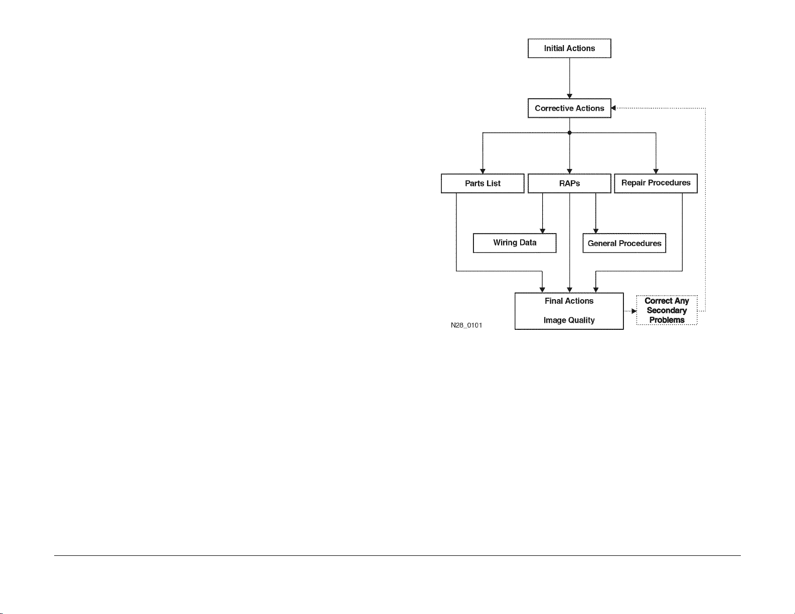
The Service Call Procedures section is used to identify a suspected problem. This section contains Call Flow, Initial Actions, Corrective Actions, and Final Actions.
Call Flow illustrates the normal activities and flow of a service call.
Initial Actions are used to gather information regarding the performance of the machine and
prepare the product for servicing.
Corrective Actions are used to verify the normal operation of the machine. In the Y/N (Yes/No)
steps of the corrective actions, a Yes response will lead you to the next step . A No response will
indicate the next step to perform or will direct you to a Repair Analysis Procedure (RAP).
RAPs will provide the instructions to isolate the faulty part or provide a list of suspect parts,
when isolation is not appropriate. Wire harnesses are not included in the repair actions and
problems with loose connections or damaged harnesses should be isolated using visual
inspection and the wiring data in section 7.
Final Actions are used to evaluate the total operation of the system and to identify the actions
required to complete the service call.
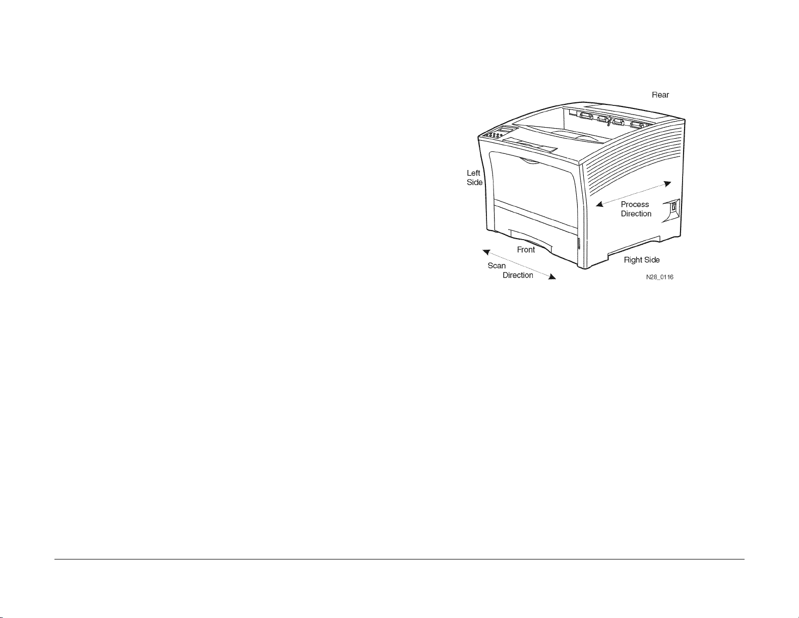
1.1 Machine Orientation
For servicing the DocuPrint N2025/N2825, all references to machine orientation are as illustrated in Figure 1.
Figure 1 Machine Orientation
Initial Issue
DocuPrint N2025/N2825
02/2000
1-3
Service Call Procedures
1.0, 1.1
Page 14
1.2 Call Flow
The call flow diagram shows the relationship of actions during a typical service call Figure 1.
The functions in Call Flow correspond to service manual sections as follows:
Section 1 - Initial Actions, Corrective Actions, and Final Actions
Section 2 - Status Indicator Repair Analysis Procedures (RAPs)
Section 3 - Image Quality Repair Analysis Procedures (IQ RAPs)
Section 4 - Repair / Adjustment (REPs)
Section 5 - Parts Lists (PLs)
Section 6 - General Procedures
Section 7 - Wiring
All service calls start with Initial Actions and all service calls end with Final Actions.
Service Call Procedures
1.2
02/2000
1-4
Figure 1 Call Flow Diagram
Initial Issue
DocuPrint N2025/N2825
Page 15

1.3 Initial Actions
Initial Actions are used to gather information from the operator concerning problems at the
local machine. Make note of symptoms, error messages, error codes or other information concerning the problem that the operator may provide. This information may help identify an intermittent or unusual problem.
Procedure
1. Ensure that the power cord is connected to the wall outlet and to the machine.
2. Check for paper or other objects in the paper path.
3. Remove all paper from the output tray(s).
4. The Rear Cover and Top Cover are closed.
5. The paper is loaded correctly in the Paper Tray(s).
6. Ask the operator to describe, or if possible, demonstrate the problem.
7. If the problem is the result of incorrect operator action, refer the operator to the User documentation or to another customer support function.
8. Refer to Section 2 if an error message is displayed.
9. If possible, print the “Configuration Sheet”. To pr int the Configuration Sheet, press and
release [1] or [5] until “Print Menu” is displayed. Then press and release [2] or [6] until
“Config Sheet” is displayed. Press Enter [4] to print the sheet. If the sheet is blank, go to
IQ RAP 2.
10. Determine that the configuration settings are correct.
11. If possible, print the “Fault History”. To print the “Fault History” press and release [1] or [5]
until “Print Menu” is displayed. Then press and release [2] or [ 6] until “Fault History” is displayed. Next, press Enter [4] to print the sheet. The Fault History will list the error codes
and the meter count when the event happened. Use the Fault History to determine the frequency of a problem. Access the Error Code Tables (Table 1 or Table 2) and perform the
corrective action as instructed.
12. If the Fault History can not be printed, the fault history can be displayed on the Control
Panel. To display the “Fault History” press and release [1] or [5] until “Print Menu” is displayed. Then press and release [2] or [6] until “Display Faults” is displayed. Next, press
press [3] to display the last f ault that occurred. Continue to press and release [3] to display
the error codes in order from the newest to the oldest. Pressing and releasing the [4] key
will display the codes in order from the oldest to the newest. The Display Faults will display the error code and the meter count when the event happened. An example of the display “E9-2 #820”, where E9-2 is the error code and #820 is the meter count.
13. Proceed to Corrective Actions.
1.4 Corrective Actions
Procedure
Ensure that Initial Conditions are met and that the Initial Actions have been completed. Switch
the main power off, wait 10 seconds, then switch the main power on. The Main Drive Motor
runs.
YN
Perform RAP 2.
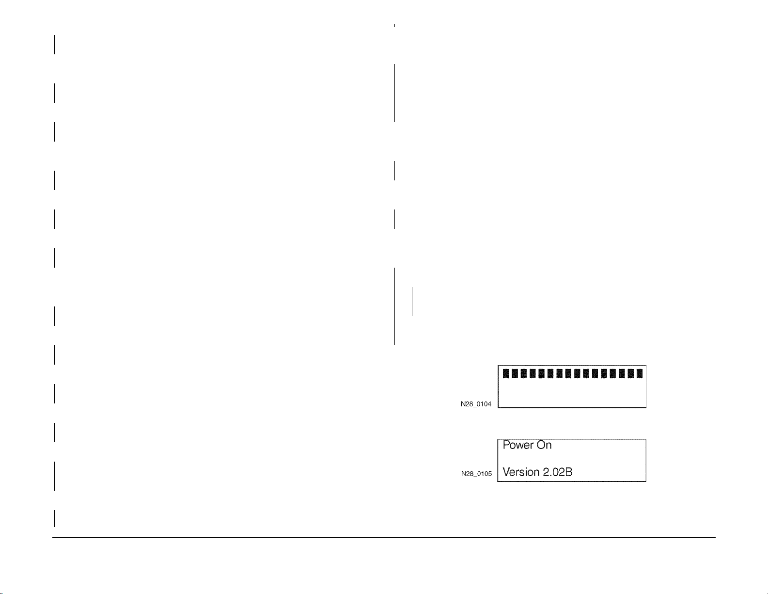
The display indicates an upper row of 16 solid squares that remain on for 1 second (Figure 1).
The display is correct.
YN
If machine indicates an error message, see the Error Code Table in section 2. If the display is blank or has garbled text, perform RAP 25.
The Main Drive Motor runs for 8 seconds, then stops.
YN
Perform RAP 16.
The Fuser Fan runs at high speed for 5 seconds, then switches to low speed.
YN
Perform RAP 20.
The LCD Panel will come on again and display “Power On” and the Power On Diagnostic
(POD) software “Version x.xxx” (Figure 2). The display is correct.
YN
Perf orm RAP 25/ RAP 26.
The Control Panel LEDs 1, 2, 3, and 4 turn on momentarily then turn off (blink).
YN
Perf orm RAP 25/ RAP 26.
The display comes on and (*) shows in the upper row (Figure 3). The display is correct.
YN
Perf orm RAP 25/ RAP 26.
A row of (*) (16) form across the top of the display (Figure 4). The display indications are
correct.
YN
Perf orm RAP 25/ RAP 26.
Initial Issue
DocuPrint N2025/N2825
A second row of (*) (16) form across the bottom of the display (Figure 5). The display indications are correct.
YN
Perf orm RAP 25/ RAP 26.
Control Panel LED 1 comes on and remains on.
YN
Perf orm RAP 25/ RAP 26.
The LCD Panel now displays the Controller Software and Version level (x.xx-xx) (Figure 6).
The display indications are correct.
02/2000
1-5
Service Call Procedures
1.3, 1.4
Page 16
YN
Perform RAP 25/ RAP 26.
The Controller Software Version switches off and the display shows “Initializing . . .“ (Figure 7).
The display is correct.
YN
Perform RAP 25/ RAP 26.
The display now shows “Copyright Xerox Corp.” (Figure 8). The display is correct.
YN
Perform RAP 25/ RAP 26.
Next, “1996-1999 All Rights Reserved” is displayed on the LCD Panel (Figure 9). The display
is correct.
YN
Perform RAP 25/ RAP 26.
Next, “Processing. . .“ is displayed on the LCD Panel(Figure 10). The display is correct.
YN
Perform RAP 25/ RAP 26.
A
Enter Diagnostics and select “Print Menu”. Scroll to “Test Print”. Feed at least 5 test prints from
all availab le trays to the Standard output tray. Test prints were successfully delivered from
each tray.
YN
If the failure occurred with:
MBF. Go to RAP 41.
Tray 1. Go to RAP 49.
Tray 2/3. Go to RAP 7.
2000 Sheet Feeder. Go to RAP 62.
If the Duplex Assembly is installed, select “Duplex On” press Enter [4]. Run at least 5 duplexed
prints. If a Duplex Assembly is not installed, follow the “Y” path. The prints were delivered
successfully.
YN
Go to RAP 56.
If a Offset Catch Tray (OCT) is installed, select “OCT” and run at least 5 prints to the OCT. If an
OCT is not installed, follow the “Y” path. Prints were successfully delivered to the OCT.
YN
Go to RAP 68.
The final display is “Ready”. The display is correct.
YN
Perform RAP 25/ RAP 26.
Press [1] twice to select “Print Menu”, then press and release [2] until “Menu Map” is displayed.
Press Enter [4] to print the “Menu Map”. First, “Processing M enu Map” is displayed, immediately followed by “Processing Tray X". The display is correct.
YN
Perform RAP 25/ RAP 26.
When the Main Driver Motor runs, the motor and all drive gears sound normal.
YN
Perform RAP 29.
Paper is fed from the paper tray to the Registration Roller and is undamaged.
YN
Perform RAP 8.
The paper feeds out of the machine and is undamaged.
YN
Perform RAP 10/ RAP 11.
The print contains readable text.
YN
If the print is black or blank perform IQ RAP 10 or IQ RAP 2. If the text is garbled, Perform RAP 44.
The print quality of the Menu Map is acceptable.
YN
Perform Image Quality Checkout.
Ensure that all normal printer conditions are set i.e. paper loaded, machine in Ready condition,
internet cable connected. Have the customer send a document to the printer. The print is
successful.
YN
Try a sending a document from a different application. The print was successful.
YN
There may be a problem with the print drivers. Have the customer contact Xerox
Customer Support.
There may be a problem with the application software. Have the customer contact Xerox
Customer Support.
Go to Final Actions.
Figure 1
Figure 2
A
Service Call Procedures
1.4
02/2000
1-6
Initial Issue
DocuPrint N2025/N2825
Page 17
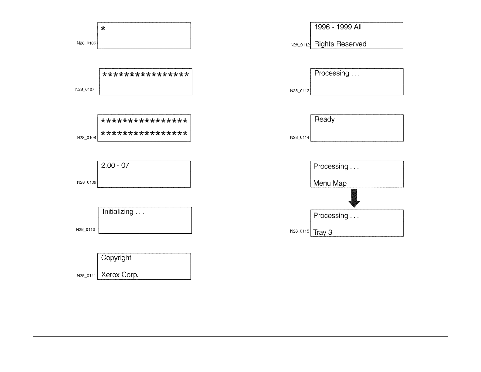
Figure 3
Figure 9
Figure 4
Figure 5
Figure 6
Figure 7
Figure 10
Figure 11
Figure 12
Initial Issue
DocuPrint N2025/N2825
Figure 8
02/2000
1-7
Service Call Procedures
1.4
Page 18

1.5 Final Actions
Procedure
1. Switch the main power off.
2. Update the tag matrix as required.
3. Reinstall all the covers removed during the service call and complete all required administrative tasks.
4. Clean the covers and ensure all labels are readable.
5. Switch the printer power on. If any of the customer selections were changed return them
to the customer’s preferred settings.
6. Run final prints and verify image quality. For Image Quality problems, go to section 3.
7. Clean the general area.
8. Communicate with the customer to inform them of actions taken and to ensure all problems have been solved.
Service Call Procedures
1.5
02/2000
1-8
Initial Issue
DocuPrint N2025/N2825
Page 19

2 Status Indicator Repair Analysis Procedures
Introduction ..................................................................................................................... 2-3
Measurements ................................................................................................................ 2-3
Error Code Table
Error Code Table................................... ................. ................. ................. ................ ....... 2-5
Base Printer
RAP 1 AC Power............................................................................................................. 2-11
RAP 2 DC Power ............................................................................................................ 2-12
RAP 3 DC Power Loading............................................................................................... 2-13
RAP 4 C3: Tray Error / Insert Tray 1,2,3......................................................................... 2-14
RAP 5 C5: Add Paper To MBF, Tray 1, 2 or 3)............................................ ................... 2-15
RAP 6 C5: Top Tray Full................................................................................................. 2-16
RAP 7 E1: Paper Jam / Tray To Registration. ................................................................ 2-16
RAP 8 E2-1: Paper Jam / Misfeed.................................................................................. 2-17
RAP 9 E2-2: Paper Jam/ Misfeed Duplex....................................................................... 2-18
RAP 10 E3: Paper Jam / Registration To Fuser ........ ................... .................................. 2-18
RAP 11 E4: Paper Jam / Exit.............................................. ................ ............................ 2-19
RAP 12 System Controller Isolation................................................................................ 2-20
RAP 13 J3: Print Cartridge Not In Position - Install/reset Print Cartridge........................ 2-21
RAP 14 J5: Toner Low.............. ................ ................. ................. ................. ................. .. 2-21
RAP 15 P1: Fuser Pause................................................................................................ 2-22
RAP 16 U1: Motor Fail / Power Off Then On .................................................................. 2-22
RAP 17 U2: ROS Fail / Power Off Then On.................................................................... 2-23
RAP 18 U4: Fuser Failure / Power Off / On .................................................................... 2-23
RAP 19 U6: NVM Fail / Power Off Then On................................................................... 2-24
RAP 20 Fan Abnormal ................................... ................ ................. ................. ............... 2-24
RAP 21 Low Paper Tray 1/2/3 ........................................................................................ 2-25
RAP 22 Paper Size Error .................................................... ................ ................. ........... 2-25
RAP 23 J5 Toner Low..................................................................................................... 2-26
RAP 24 Inoperative Printer ............................................................................................. 2-27
RAP 25 Malfunctioning LCD/LED ................................................................................... 2-28
RAP 26 Inoperative Keypad............................................................................................ 2-29
RAP 27 Erratic Printer Operation.................................................................................... 2-29
RAP 28 Power Supply..................... ................. ................ ................. ................. ............. 2-30
RAP 29 Main Motor Assembly........................................................................................ 2-31
RAP 30 Laser Assembly................................................................................................. 2-32
RAP 31 Fuser Assembly................................................................................................. 2-33
RAP 32 Registration Sensor........................................................................................... 2-34
RAP 33 MBF No Paper Sensor.................................. ..................................................... 2-34
RAP 34 Tray 1 No Paper Sensor.................................................................................... 2-35
RAP 35 Stack Full Sensor............................................................................................... 2-36
RAP 36 E5: MBF Extended / Insert MBF. ....................................................................... 2-37
RAP 37 Size Switch ........................................................................................................ 2-38
RAP 38 Registration Clutch ............................................................................................ 2-39
RAP 39 Turn Roll Clutch Assembly .... ................. ................. ................ ................. ......... 2-40
RAP 40 Tray 1 Feed Solenoid ........................................................................................ 2-41
RAP 41 MBF Feed Solenoid.............................. ................. ................ ................. ........... 2-41
RAP 42 Toner Sensor Assembly.................................... ................. ................ ................ 2-42
RAP 43 HVPS Assembly................................................................................................. 2-42
RAP 44 Electrical Noise.............................. ................. ................. ................ ................. . 2-43
RAP 45 0101 - DIMM 1.................................................. ................. ................ ................ 2-44
RAP 46 0102 - DIMM 2.................................................. ................. ................ ................ 2-45
RAP 47 0101 - DIMM 3.................................................. ................. ................ ................ 2-45
500 Sheet Feeder
RAP 48 Exit Sensor......................................................................................................... 2-47
RAP 49 E2-1: Paper Jam / Misfeed 500 Sheet Feeder................................... ................ 2-47
RAP 50 Low Paper Tray 2 (or Tray 3) 500 Sheet Feeder............................................... 2-48
RAP 51 500 Sheet Feeder Feed Solenoid......................... .................................... ......... 2-49
RAP 52 500 Sheet Feeder Assembly Not Recognized............................... .................... 2-50
RAP 53 500 Sheet Feeder Feed Motor............. ................. ................. ................. ........... 2-51
RAP 54 C3: Tray Out / Install Tray 2 (or Tray 3)............................................................. 2-52
RAP 55 Pre-Registration Sensor........................................................................ ............. 2-52
RAP 56 C5: Add Paper To Tray 2 (or Tray 3) .............................................................. ... 2-53
Duplex Unit
RAP 57 E7: Duplex Jam................. ................................................. ................ ................ 2-55
RAP 58 E5: Top/R Cover................................................................................................ 2-56
RAP 59 C5: Output Tray Full................. ................ ................. ................. ................. ....... 2-56
RAP 60 Duplex Fail................................... ................. ................ ................. ................. ... 2-57
2000 Sheet Feeder
RAP 61 C5: Wrong Size For Duplex ................... ................. ................. ................. ......... 2-59
RAP 62 E2-1:Paper Jam/Misfeed 2000 Sheet Feeder.............................. ...................... 2-59
RAP 63 C3: 2000 Sheet Feeder Carriage Not In Position ....... ....................................... 2-60
RAP 64 C5: Add Paper To 2000 Sheet Feeder ......................... ..................................... 2-60
RAP 65 E5: 2000 Sheet Feeder CVR Open / Please Close CVR................. .................. 2-61
RAP 66 E9:HCF Fail (2000 Sheet Feeder).................. ................................... ................ 2-61
RAP 67 C5: OCT Tray Full.................. ............................................................................ 2-62
Offsetting Catch Tray
RAP 68 E8: OCT Jam ..................................................................................................... 2-63
RAP 69 E5: OCT CVR Open / Please Close CVR.......................................................... 2-64
RAP 70 OCT Motor Assembly................................................................. ........................ 2-64
RAP 71 E9: OCT Fail...................................................................................................... 2-65
RAP 72 Offset Operation Not Performed..................................................................... ... 2-65
RAP 73 OCT Sensor........................................... ............................................................ 2-66
Initial Issue
DocuPrint N2025/N2825
02/2000
2-1
Status Indicator Repair Analysis Procedures
Page 20

Status Indicator Repair Analysis Procedures
02/2000
2-2
Initial Issue
DocuPrint N2025/N2825
Page 21

Introduction
The Repair Analysis Procedures section is used to isolate and identify problems to a faulty
component or subassembly. It contains the Introduction, display message table, error code
table and the Repair Analysis Procedures (RAPs).
Measurements
Power and signal grounds are connected to frame ground, therefore all circuit troubleshooting
can be performed using the metal frame (chassis) as the grounding point. If more information is
needed to locate connectors or test points, refer to section 7.
Use the Display Messages and Error Codes tables when messages are displayed or error
codes are printed in a report.
The Repair Analysis Procedures (RAPs) are acce ssed from Sect ion 1, system checks or additional checks. There are two types of RAPs: Status Indicator (SI) RAPs, contained in this section, and Image Quality (IQ) RAPs, located in Section 3.
RAPs will normally isolate a problem to a specific component or s ubassembly, excluding the
wire harnesses.
In the Y/N (Yes/No) steps of the RAPs, a Yes/No response will either lead you to the next step
or will indicate a corrective action. When the indicated corrective action has been completed,
go to Section 1 and restart the System Check to verify that the problem has been corrected.
Unless otherwise specified, the following voltage tolerances are used within this section: Table
1
Table 1 Voltage Measurements
Stated Measured
+3.3 VDC +3.0 to 3.6 VDC
+5.0 VDC +4.8 to +5.2 VDC
+24.0 VDC +21.6 to +26.4 VDC
0.0 VDC Less than +0.5 VDC
Initial Issue
DocuPrint N2025/N2825
02/2000
2-3
Status Indicator Repair Analysis Procedures
Introduction, Measurements
Page 22

Status Indicator Repair Analysis Procedures
Introduction, Measurements
02/2000
2-4
Initial Issue
DocuPrint N2025/N2825
Page 23

Error Code Table
Comments On LIne Message Fault History Entry Diagnostic Message Error Description Action
2000 Sheet Feeder
installed as Tray 2
2000 Sheet Feeder
installed as Tray 3
Table 1 Error Code Table
IOT NVM Fail
Power Off/On
Motor Failure
Power Off/On
Laser Failure
Power Off/On
Fuser Failure
Power Off/On
Fan Failure
Power Off Now
Close Offset Door E5: OCT Rear Door OCT rear door interlock switch is open. Close OCT rear door
Close Tray 2
Rear
Close Tray 3
Rear
U6 U6: NVM Fail 1. A read error is detected during
power on.
2. A write error is detected during
write to the Nonvolatile Memory.
U1 U1: Motor Fail Motor Fail signal is declared 0.75 sec-
onds after start of Main Motor.
U2 U2: ROS Fail 1. Laser Signal intervals are longer
than the Ready time interval 20 seconds after the start of Laser warm
up.
2. The laser power does not reach the
value in NVM when the laser diode
is switched on after the start of
Laser warm up.
3. Laser signal intervals become
longer than the Fail time interval
after Laser warm up is completed.
U4: Fuser Fail 1. Fuser temperature drops below the
set temperature after the Fuser
warm up is complete.
2. Fuser warm up does not complete
within 110 seconds.
3. Thermistor circuit is detected to be
open.
4. Fuser temperature rises above the
set temperature.
5. Heat rod is on for 10 seconds when
the Main Drive Motor is stopped,
after the Fuser warm up is completed.
U5 U5: Fan Fail 1. Fuser Fan has failed.
2. LVPS Fan has failed.
E5: HCF Cover 2000 Sheet Feeder rear cover interlock
switch is open
E5: HCF Cover 2000 Sheet Feeder rear cover interlock
switch is open
Power Off and On
Go to RAP 19
Power Off and On
Go to RAP 16
Power Off and On
Go to RAP 17
Power Off and On
Go to RAP 18
Check the Fuser Fan and the
LVPS Fan.
Power Off and On
Go to RAP 20
Go to RAP 69
Close 2000 sheet feeder rear
cover
Go to RAP 65
Close 2000 sheet feeder rear
cover
Go to RAP 65
Initial Issue
DocuPrint N2025/N2825
02/2000
2-5
Status Indicator Repair Analysis Procedures
Error Code Table
Page 24

Table 1 Error Code Table
Comments On LIne Message Fault History Entry Diagnostic Message Error Description Action
Close Covers E5: Top/R Cover 1. Top cover interlock is open.
Insert MBF E5: MBF Extend MBF Assy. is not closed. Close MBF
Install
Print Cartridge
Duplex Jam
Open Rear Cover
Clear Paper Path
Exit Jam-Open
Rear & Top Cover
Remove Print Cartridge
Clear Paper Path
Paper Jam
Open Top Cover
Remove Print Cartridge
Clear Paper Path
MBF misfeed Paper Jam
Open Top Cover
Lift /Extend MBF
Remove All Paper
2. Rear cover interlock is open.
J3: EP Cartridge 1. Print Cartridge is not installed
2. The installed Print Cartridge is not
the correct one.
E7-1 E7: Duplex Jam 1. Duplex Sensor is not actuated
within the time after the start of the
Duplex drive motor in reverse.
2. Duplex sensor is being actuated at
power up.
3. Duplex Sensor is on when the interlock is closed.
E4-0 E-4: Exit Jam 1. Exit sensor is not deactuated within
time after it is actuated.
2. Exit sensor is being actuated at
power up.
3. Exit Sensor is ON when the interlock is closed.
4. Exit Sensor turns from OFF to ON
at Erase Cycle.
E3-1 E3: Reg. Jam Exit Sensor did not actuate within time
after the Registration clutch is actuated.
E2-1M E2-1 Misfeed Jam 1. Simplex printing: Reg. Sensor is
OFF when the specified time has
passed timing from Feed Roll ON.
2. Printing from 2000 Sheet Feeder:
Reg. Sensor is OFF when the timing is after receiving Feed_Run status.
Close Top Cover
Close Rear Cover
Go to RAP 58
Install the Print Cartridge, or
replace with the correct Print
Cartridge
Go to RAP 13
Open the Rear Cover and
remove any paper.
Go to RAP 57
Open Top Cover, remove EP
Cartridge and remove any
paper.
Go to RAP 11
Open Top Cover, remove EP
Cartridge and remove any
paper.
Go to RAP 10
Open Top Cover or Feeder and
remove the sheets. Then close
the cover.
Go to RAP 8
Tray 1 Misfeed Tray 1 Jam
Open Tray 1
Lift/Extend MBF
Open Top Cover
Remove Printery
Clear Paper Path
Status Indicator Repair Analysis Procedures
Error Code Table
E2-11 E2-1 Misfeed Jam 1. Simplex printing: Reg. Sensor is
OFF when the specified time has
passed timing from Feed Roll ON.
2. Printing from 2000 Sheet Feeder:
Reg. Sensor is OFF when the timing is after receiving Feed_Run status.
02/2000
2-6
Open Top Cover or Feeder and
remove the sheets. Then close
the cover.
Go to RAP 8
Initial Issue
DocuPrint N2025/N2825
Page 25

Table 1 Error Code Table
Comments On LIne Message Fault History Entry Diagnostic Message Error Description Action
Tray 2 misfeed with
500 Sheet Feeder
installed as Tray 2
Tray 3 Misfeed with
500 Sheet Feeder
installed as Tray 3
Tray 2 misfeed with
2000 Sheet Feeder
installed as Tray 2
Tray 3 misfeed with
2000 Sheet Feeder
installed as Tray 3
Jam in the OCT Offset Jam
Tray 2 Jam
Open Tray 2
Lift/Extend MBF
Open Top Cover
Remove PrintCart
Clear Paper Path
Tray 3 Jam
Open Tray 3
Lift/Extend MBF
Open Top Cover
Remove PrintCart
Clear Paper Path
Tray 2 Jam
Open Tray 2
Open Rear Trader
Clear Paper Path
Tray 3 Jam
Open Tray 3
Open Rear TrayDr
Clear Paper Path
Duplex Jam
Open Rear Cover
Clear Paper Path
Open Rear Cover
Open Offset Door
Clear Paper Path
Paper Jam
Open Top Cover
Lift/Extend MBF
Remove PrintCart
Clear Paper Path
E2-12 E2-1 Misfeed Jam 1. Simplex printing: Reg. Sensor is
OFF when the specified time has
passed timing from Feed Roll ON.
2. Printing from 2000 Sheet Feeder:
Reg. Sensor is OFF when the timing is after receiving Feed_Run status.
E2-13 E2-1 Misfeed Jam 1. Simplex printing: Reg. Sensor is
OFF when the specified time has
passed timing from Feed Roll ON.
2. Printing from 2000 Sheet Feeder:
Reg. Sensor is OFF when the timing is after receiving Feed_Run status.
E2-D E2-2: Misfeed Jam Registration Sensor did not actuate
within time after the actuation of the
Duplex Motor in reverse.
E8-1 E8-OCT Jam 1. OCT sensor did not actuate within
time after the actutation of the Exit
sensor.
2. OCT sensor is not deactuated
within time after actuation of OCT
Sensor.
3. OCT sensor is actuated at power
on.
E1-1 E1: Reg. Jam 1. Registration Sensor did not deactu-
ate within time after actuation of
Registration sensor.
2. Registration sensor is actuated at
power on.
3. Registration is actuated during
warm up cycle or an erase cycle.
Open Top Cover or Feeder and
remove the sheets. Then close
the cover.
Go to RAP 49
Open Top Cover or Feeder and
remove the sheets. Then close
the cover.
Go to RAP 49
Open Top Cover or Feeder and
remove the sheets. Then close
the cover.
Go to RAP 62
Open Top Cover or Feeder and
remove the sheets. Then close
the cover.
Go to RAP 62
Open Rear Cover and remove
any paper.
Go to RAP 9
Open OCT rear door and
remove any paper.
Open Rear cover and remove
any paper.
Go to RAP 68
Open Top Cover, remove EP
Cartridge, Lift and Extend MBF
assy and remove any paper.
Go to RAP 7
Initial Issue
DocuPrint N2025/N2825
02/2000
2-7
Status Indicator Repair Analysis Procedures
Error Code Table
Page 26

Table 1 Error Code Table
Comments On LIne Message Fault History Entry Diagnostic Message Error Description Action
2000 Sheet Feeder
installed as Tray 2
2000 Sheet Feeder
installed as Tray 3
Duplex Unit Fail or
Removed
Offset Bin Fail
Power Off/On
Tray 2 Failure
Power Off/On
Tray 3 Failure
Power Off/On
Paper Size Jam
Open Rear Cover
Insert T r ay 1 C3:Tray 1 Error Tray 1 is not detected in printer. (all paper
Insert T r ay 2 C3: T ra y 2 Error Tra y 2 is not detected in printer. (all paper
Insert T r ay 3 C3: T ra y 3 Error Tra y 3 is not detected in printer. (all paper
Load Tray 1 C5:Tray 1 Empty Tray 1 is out of paper Load paper into Tray 1
Load Tray 2 C5:Tray 2 Empty Tray 2 is out of paper Load paper into Tray 2
Load Tray 3 C5:Tray 3 Empty Tray 3 is out of paper Load paper into Tray 3
Load MBF C5:MBF Empty MBF is out of paper Load paper into MBF
Remove Output
from St. Bin
Remove Output
from Offset Bin
Toner Low J5:Toner Low Toner Low is detected after 10 prints
Memory Failure
Power Off/On
E9-1 E9:Duplex Fail Duplex module removed while power is
on.
E9-2 E-9:OCT Fail OCT removed while power is on. Reinstall OCT
E9-3 E-9:HCF Fail 2000 Sheet Feeder remov ed while power
is on.
E9-3 E-9:HCF Fail 2000 Sheet Feeder remov ed while power
is on.
EO:HCF Elevator 1. 2000 Sheet Feeder elevator did not
reach home position within the prescribed time.
2. Paper level sensor on when 2000
Sheet Feeder Tray is Opened.
PSE-1 Paper Size Error There is a conflict between the size of
the paper, which is detected by the Size
Switches, and the length of paper the
printer detects by the length of time the
Registration Sensor is actuated.
size switches not actuated)
size switches not actuated)
size switches not actuated)
C5: T op T r ay Full Top Tray is declared full when 5 prints are
delivered to the top tray after the Full
Stack sensor is actuated.
C5:OCT Tray Full 5 prints are delivered to the top tray after
the OCT Full Stack sensor is actuated.
while toner sensor is on.
ESS-M N/A Controller memory has failed (32 me on
board).
Reinstall Duplex Module
Go to RAP 60
Go to RAP 71
Reinstall HCF
Go to RAP 66
Reinstall HCF
Go to RAP 66
Open and close 2000 Sheet
Feeder paper tray.
Correct the mismatch
Go to RAP 22
Install Tray 1
Go to RAP 4
Install Tray 2
Go to RAP 4
Install Tray 3
Go to RAP 4
Go to RAP 5
Go to RAP 5
Go to RAP 5
Go to RAP 5
Empty Top Tray
Go to RAP 6
Empty OCT Tray
Go to RAP 67
Replace Print Cartridge
Go to RAP 14
Go to RAP 23
Po wer Off/On
Remove Options
Replace System Controller
PWB (REP 8.1)
Go to RAP 12
Status Indicator Repair Analysis Procedures
Error Code Table
02/2000
2-8
Initial Issue
DocuPrint N2025/N2825
Page 27
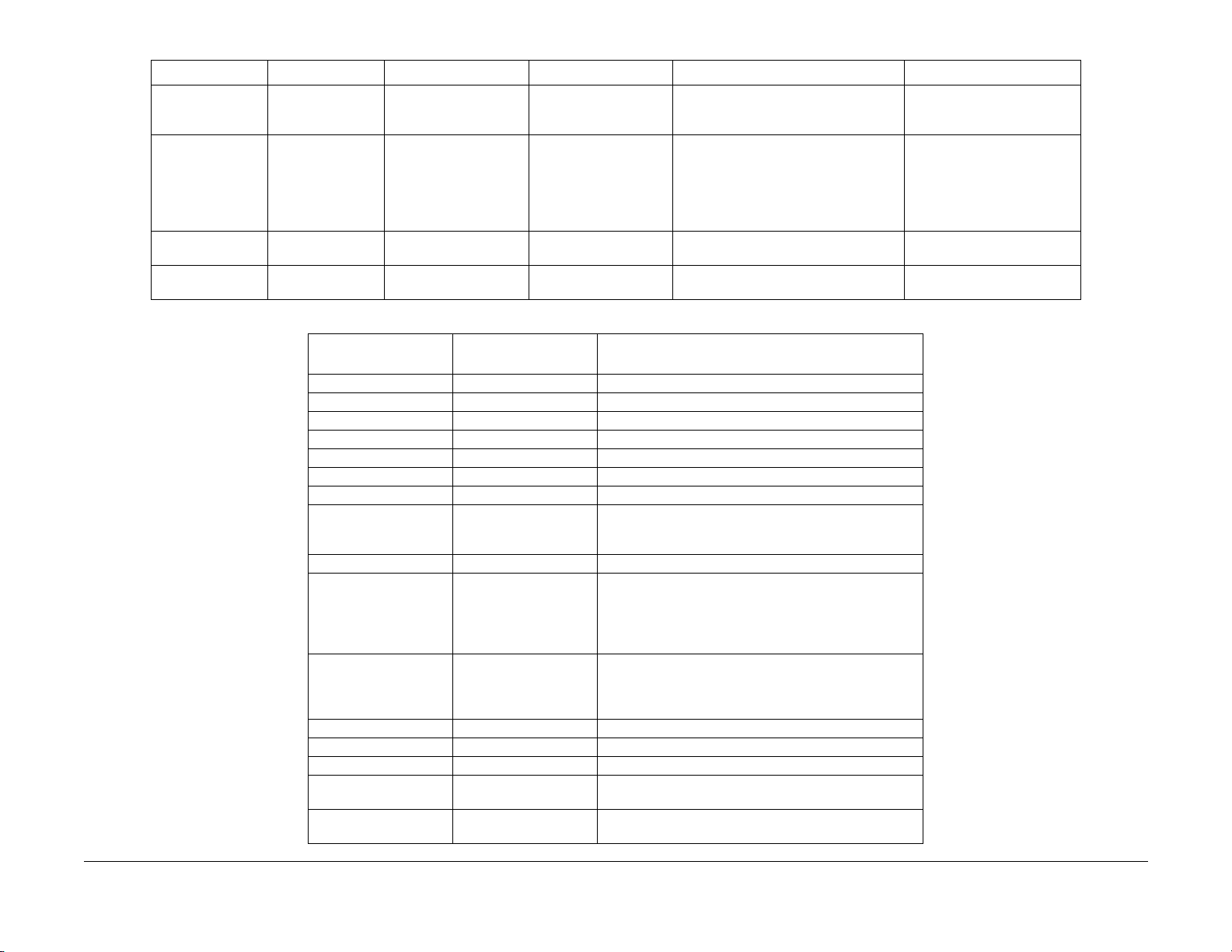
Table 1 Error Code Table
Comments On LIne Message Fault History Entry Diagnostic Message Error Description Action
NV Memory Fail
Power Off/On
Disk Error
Format Disk
Init Failed
Disk Locked
Format Failed
Disk Locked
Control Panel Message
0001 - System Controller 1 System Controller Board major failure. Go to RAP 12.
0001 - BASE RAM 2 System Controller Board RAM failure. Go to RAP 12.
0001 - BASE ROM 3 System Controller Board boot ROM. Go to RAP 12.
0001 - ASIC 4 System Controller Board ASIC failure . Go to RAP 12.
0001 - TIMER 4 System Controller Board Timer failure. Go to RAP 12.
0001 - PWPM 5 System Controller Board PWPM failure. Go to RAP 12.
0001 - DMA 5 System Controller DMA failure. Go to RAP 12.
0001 - COMM 6 System controller parallel port failure, USB port failure, E-
0001 - USB 6 Replace the System Controller PWB (REP 8.1)
1000 - IOT 8 System Controller - IOT handshake failure.
0010 - DISK 9 Hard disk failure.
0101 - DIMM1 10 DIMM board 1 failure. Go to RAP 45.
0102 - DIMM2 11 DIMM board 2 failure. Go to RAP 46.
0103 - DIMM3 12 DIMM board 3 failure. Go to RAP 47.
2000 - XIE RAM 15 System Controller Xerox Image Enhanced PWPM failure.
2010 - XIE PWPM 15 System Controller Xerox Image Enhanced PWPM failure.
ESS-N N/A Controller NVM Failure P ower Off/On
D-1 N/A Hard Drive error was detected. Power Off/On
D-2 N/A Cannot format disk, disk locked via PJL
or SNMP Command.
D-3 N/A Cannot put disk in factory default attempt
to initialize disk after it is locked.
Table 2 System Controller Error Code Table
LED # blinks
Followed by 1 sec. off Comment
Net Port Failure.
Replace System Controller PWB (REP 8.1)
Remove and reinstall the System Controller PWB (REP
8.1).
Replace the System Controller PWB (REP 8.1).
Replace the Print Engine Controller PWB (REP 8.5).
Format Hard Disk (see Reset Menu GP 3.3).
Replace the Hard Disk (PL 9.1).
Replace the System Controller PWB (REP 8.1).
Replace the System Controller PWB (REP 8.1).
Replace the System Controller PWB (REP 8.1).
Replace System Controller
PWB (REP 8.1)
Format Hard Drive (See Reset
Menu GP 3.3)
Replace Hard Drive (PL 9.1)
Replace System Controller
PWB (REP 8.1)
Customer Unlock Disk
Replace Hard Disk (PL 9.1)
Customer Unlock Disk
Replace Hard Disk (PL 9.1)
Initial Issue
DocuPrint N2025/N2825
02/2000
2-9
Status Indicator Repair Analysis Procedures
Error Code Table
Page 28

Table 2 System Controller Error Code Table
Control Panel Message
2020 - XIE VDMA 15 System Controller Xerox Image Enhanced VDMA failure.
3000 - Token Ring
3000 - Serial
3000 - E-Net (10 Base 2)
5000 - Memory None Memory size not large enough to load the system software
LED # blinks
Followed by 1 sec. off Comment
Replace the System Controller PWB (REP 8.1).
16 Replace the appropriate network card (PL 9.1).
Replace System Controller PWB (REP 8.1).
Download Data.
Replace System Controller PWB (REP 8.1).
Status Indicator Repair Analysis Procedures
Error Code Table
02/2000
2-10
Initial Issue
DocuPrint N2025/N2825
Page 29
RAP 1 AC Power
Initial Actions
Disconnect the AC power cord from the wall outlet.
WARNING
Improper connection of the grounding conductor can result in the risk of electrical
shock. The following must be observed:
• Never use a ground adapter plug to connect the machine to a power source.
• Never attempt any maintenance function which is not specifically called out in the
service procedures.
• Never remove any covers which are fastened with screws, unless so instructed in
the service procedures.
CAUTION
If any of the voltage measurements are not as specified in the following steps, the cause must
be corrected. Caution the customer NOT to connect the machine to the wall outlet. Advise the
customer that a licensed electrician must correct the wiring. Do not attempt to correct the wiring yourself. If you later find the condition has not been corrected, inform your manager in writing of the improper wiring.
Procedure
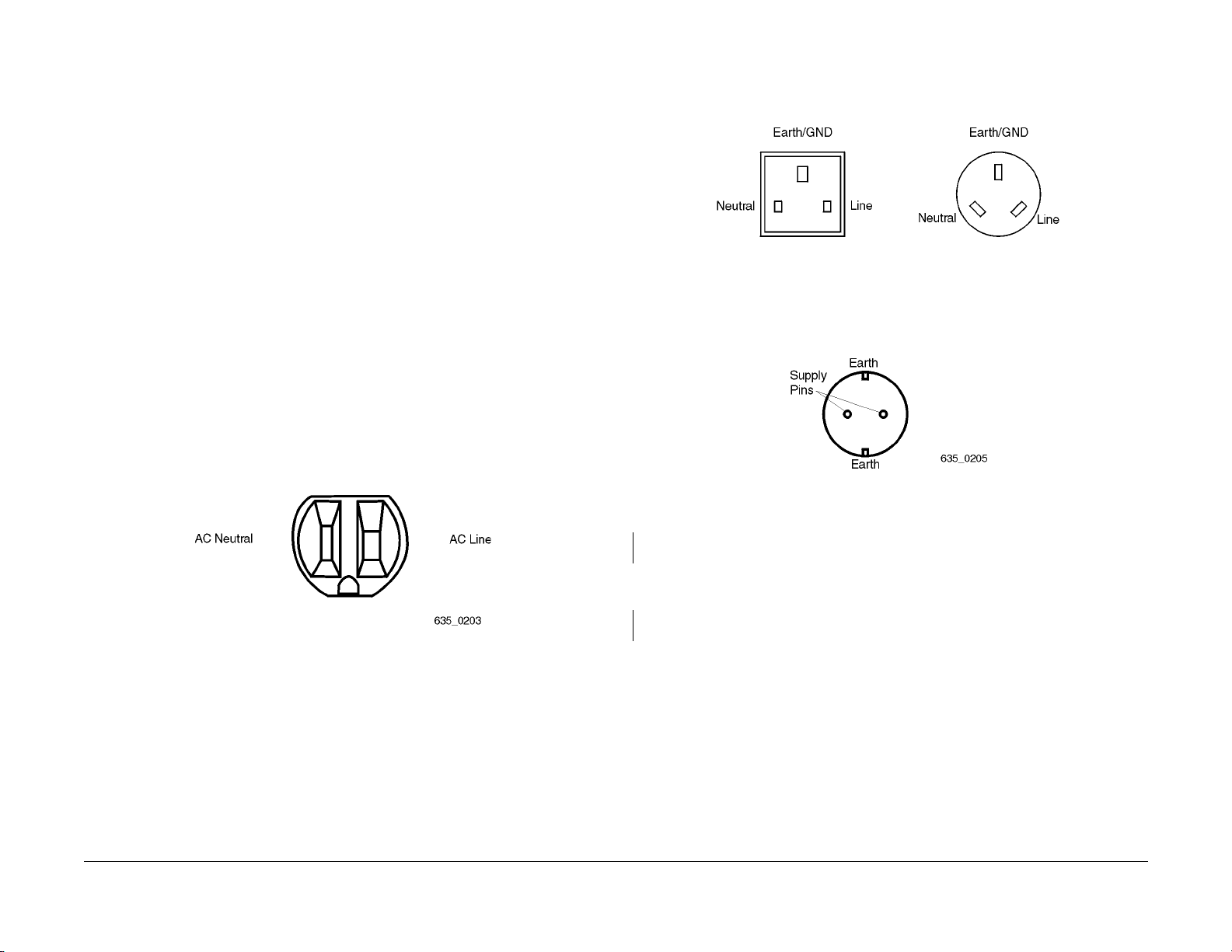
Perform one of the following line voltage checks:
US, XCI, and AO (115 VAC) Figure 1. Perform the following:Measure the AC voltage between
AC Line and Neutral, between AC Line and Ground, and between AC Neutral and Ground. The
voltage between Line and Neutral and between Line and Ground is 104 to 127 VAC and the
voltage between Neutral and Ground less than 3 VAC.
XL, UK and AO (220 VAC) Figure 2. Perform the following:Measure the AC voltage between
Line and Neutral, between Line and Earth/Ground, and between Neutral and Earth/Ground.
The voltage between Line and Neutral and between Line and Earth/Ground is 216 to 264 VAC
and between Neutral and Earth/Ground is less than 3 VAC.
Figure 2 XL, UK, and AO (220 VAC) Outlet.
XL, Europe (220 VAC) Figure 3. Perform the following: Measure the AC voltage between the
supply pins, then between a supply pin and earth, then between the other supply pin and earth.
The voltage is 196 to 244 VAC between the supply pins and between one of the supply pins
and earth. Between the other supply pin and earth is less than 3 VAC.
Figure 3 XL, Europe (220 VAC) Outlet.
Initial Issue
DocuPrint N2025/N2825
Figure 1 US, XCI, and AO (115 VAC) Outlet.
The voltage measured is correct.
YN
Inform the customer of insufficient voltage or improper wiring.
Check the continuity through all connections of the power cord. The measurement is less
than 10 ohms for each connection.
YN
Replace the power cord (PL 9.2) as applicable.
Perf orm RAP 2.
02/2000
2-11
Status Indicator Repair Analysis Procedures
RAP 1
Page 30

RAP 2 DC Power
This procedure is used to troubleshoot the Low Voltage Power Supply.
Procedure
Perf orm RAP 1 before starting this RAP. If RAP 1 checks out OK, switch the main power off and
disconnect the printer power. Remove the Lower Rear Cover (REP 1.7). Connect printer power.
Switch the printer power on. Measure the voltage on the LVPS between P/J167 pins 1 and 3.
The voltage matches the line voltage.
YN
Replace the AC Input Assembly (REP 8.8).
Measure the voltage between the bottom of Fuse F101 and P/J167 pin 3. The voltage
matches the line voltage.
YN
Switch the main power off. Replace fuse F101. Switch the main power on. Measure the
voltage between the bottom of Fuse F101 and P/J167 pin 3. The voltage matches the
line voltage.
YN
Replace the LV PS (R EP 8.6).
Problem Solved.
Measure the voltage between LVPS P/J162 pin 3 and frame ground. The voltage is +24VDC.
YN
On the LVPS, measure the voltage between P/J162 pin 1 and frame ground. The voltage
is +24VDC
YN
Replace the LV PS (REP 8.6).
A
Return to Initial Actions or to the procedure that sent you here.
Check the Top Cover and the printer Upper Rear Cover. Both covers are properly
closed and actuating the interlock switches.
YN
Repair or replace the defective cover/interlock switch as necessary.
Check the continuity through the interlock switches. Replace if necessary (REP 7.5/REP
10.13).
Check the voltages listed in Table 1.
Table 1 LVPS
Red Lead Black Lead Voltage
P/J161 pin 10 Frame Ground +5.0VDC
P/J161 pin 11 Frame Ground +3.3VDC
P/J161 pin 3 Frame Ground +24.0VDC
All voltages in Table 1 are correct.
YN
Go to RAP 3.
A
Status Indicator Repair Analysis Procedures
RAP 2
02/2000
2-12
Initial Issue
DocuPrint N2025/N2825
Page 31

RAP 3 DC Power Loading
Initial Actions
Perform RAP 2 DC Power before starting this RAP.
WARNING
AC input voltages can be lethal. Use extreme care while checking the voltages on the
LVPS.
Disconnect the power cord whil e chec ki ng the contin uity of fuses and whi le remo ving or
reinstalling the components.
Procedure
Switch the printer power off. Remove the Lower Rear Cover (REP 1.7). Disconnect the following from the LVPS:
• P/J161 (Print Engine Controller PWB)
• P/J163 (System Controller PWB)
• P/J164 (Main Motor)
• P/J165 (Main Fan)
• P/J166 (LVPS Fan)
• P/J168 (5VDC Power Supply)
Switch the printer power on and measure the voltages listed in Table 1 on the LVPS.
Table 1 LVPS
Red Lead Black Lead Voltage
P/J161 pin 10 Frame Ground +5.0VDC
P/J161 pin 11 Frame Ground +3.3VDC
P/J161 pin 3 Frame Ground +24.0VDC
A
• P/J20 (Tray 1 Size Sensor/MBF Home Sensor)
Switch the printer power on and measure the voltages listed in Table 1. All voltages are
correct.
YN
Replace the Print Engine Controller PWB (REP 8.5).
Switch the printer power off. Reconnect one of the disconnected plugs. Switch the printer
power on. Measure the voltages listed in Table 1. All the voltages are correct.
YN
Replace the component just connected to the Print Engine Controller PWB.
Repeat the step with the next disconnected plug.
Switch the printer power off. Reconnect one of the disconnected plugs. Switch the printer
power on. Measure the voltages listed in Table 1. All the voltages are correct.
YN
Replace the component just connected to the LVPS.
Repeat the step with the next disconnected plug.
All voltages are correct.
YN
Replace the LV PS (R EP 8.6).
Switch the printer power off. Reconnect P/J161 to the LVPS. Switch the printer power on and
measure the voltages listed in Table 1. All the voltages are correct
YN
Switch the printer power off. Remove the Left Side Cover and the Print Engine Controller
PWB Cover. Reconnect all the P/Js to the LVPS. Disconnect the following from the Print
Engine Controller PWB:
• P/J11 (Laser)
• P/J21 (Print Cartridge Sensor)
• P/J14 (Toner Sensor)
• P/J12 (Tray 1 Feed head components/Tray 1 Low Paper Sensor)
• P/J22 (Registration Clutch)
• P/J13 (Feeder 2/3)
• P/J17 (Fuser Control PWB / Fuser)
• P/J19 (Duplex Assembly/OCT)
• P/J18 (HVPS/Registration Sensor)
A
Initial Issue
DocuPrint N2025/N2825
02/2000
2-13
Status Indicator Repair Analysis Procedures
RAP 3
Page 32

RAP 4 C3: Tray Error / Insert Tray 1,2,3
Tray Assembly (Tray 1, Tray 2, or Tray 3) are not in place.
Procedure
Enter Diagnostics and select Test Print. Run a test print from every tray (see section 6). The
Error Code specifies Tray 2 or Tray 3.
YN
Remove and reinstall Tray 1. The C3 error code still appears.
YN
Problem solved.
Inspect the Paper Stack End Guide position in the tray. The End Guide is snug against
the paper stack.
YN
Adjust the End Guide to contact the paper stack.
Enter Component Test, select Tray 1 Size. Press the Enter Key (key 4). The paper size
indicated on the LCD matches the paper size actually in Tray 1.
YN
Remove Tray 1. Enter Component Test - Sensor Input test. One at a time, press and
release each of the Tray 1 size actuators. The number on the LCD increments
each time you press and release one of the actuators.
YN
Go to RAP 37
Check the size cam on the left side of the paper tray. The cams are in good condi-
tion (not broken) and rotate freely as the paper tray end guide is moved.
YN
Replace Tray 1 (PL 2.1/ PL 2.2).
B
Replace the Print Engine Controller PWB ( REP 8.5). If the problem persists, replace the
System Controller (REP 8.1).
Go to RAP 45 (for 500 Sheet Feeder) or RAP 64 (for 2000 Sheet Feeder).
Remove the Left Side Cover (REP 1.1). As you insert Tray 1, watch the size actuators (visible under the Print Engine Controller PWB metal cover) move depending on
the setting of tray 1. See Table 1.
Table 1 Paper Size Actuators
8.5
A4
Actuator
4 Top x xxxx
3 xxx xx
2 xxx x
1 Bottomxxxx
The Tray 1 Size Cams contact the Paper Size Actuators correctly for each size
of paper .
YN
Replace the Tray 1 Left Guide Assembly (REP 3.6).
AAB
Status Indicator Repair Analysis Procedures
LEF
Replace Tray 1 (PL 2.1/ PL 2.2)). If the problem persists, replace the Tray 1 Left
Guide Assembly (REP 3.6).
LEF
B5
LEF
RAP 4
A5
LEF
14"
SEF
8.5"
SEF
A4
SEF
B4
SEF
02/2000
2-14
Initial Issue
DocuPrint N2025/N2825
Page 33

RAP 5 C5: Add Paper To MBF, Tray 1, 2 or 3)
Procedure
The problem appears when using Tray 2 or 3.
YN
Check the paper level in Tray 1. There is at least 100 sheets of paper in Tray 1.
YN
Load paper into Tray 1.
Check the paper level in the MBF. There is paper in the MBF.
YN
Load paper into the MBF.
Enter Diagnostics and select Test Print. Run a test print from the MBF Tray (see section
6). The C5 error code appears when you feed paper from MBF.
YN
Run a test print from the Tray 1. The C5 error code appears when you feed paper
from Tray 1.
YN
Return to Initial Actions and restart.
Remove Tray 1 from the printer. Remove the Tray Cover, if installed, and all paper
from the tray. Insert Tray 1 into the printer and inspect the Bottom Plate. The Bot-
tom Plate is raised fully and evenly.
YN
Replace the Tray 1 Assembly (PL 2.1/ PL 2.2).
Remove Tray 1. Manually actuate the Tray 1 No P aper and Low Paper sensors. The
No Paper and Low P aper Actu a tors move smoothly.
YN
Replace the Tray 1 No Paper Actuator (REP 2.6) or Low Paper Actuator (PL
3.1).
A
YN
Go to RAP 33.
Replace the Print Engine Controller PWB (REP 8.5).
Go to RAP 47.
NOTE: W hen checking the Low Paper Sensor using the Sensor Test, at least one
Paper Size switch and the Low Paper Sensor must be actuated.
Enter Diagnostics and select Component Test. Scroll to Sensor Input Test and press
Enter. Manually actuate the Tray 1 No Paper and Low Paper Sensors. The number
on the LCD increments each time you press and release one of the actuators.
YN
Go to RAP 34.
Replace the Print Engine Controller PWB (REP 8.5).
Insert then remove a piece of paper into the MBF. The MBF No Paper Actuator moves
smoothly when paper is inserted then removed.
YN
Repair or replace the actuator, as necessary.
Enter Diagnostics and select Component Test. Scroll to Sensor Input Test and press
Enter. Manually actuate the MBF No Paper Sensor. The number on the LCD incre-
ments each time you press and release the actuator.
A
Initial Issue
DocuPrint N2025/N2825
02/2000
2-15
Status Indicator Repair Analysis Procedures
RAP 5
Page 34

RAP 6 C5: Top Tray Full
Error code indicates the Top Tray is full.
Procedure
There is a paper stack on the Top Cover close to the Stack Full Actuator.
YN
The paper is curled.
YN
Open the Rear Cover . Press and release the Stack Full Actuator. The flag of the
Stack Full Actuator alternately clears and obscures the detecting points of the
sensor when the actuator is moved.
YN
Replace Stack Full Actuator (REP 5.3) or Sensor (REP 5.2) as necessary.
RAP 7 E1: Paper Jam / Tray To Registration.
There is a paper jam between the Paper Tray / Paper Handler Assembly and the Registration
Sensor.
Procedure
Inspect the Registration Actuator. There is foreign material blocking the Registration Actuator.
YN
Enter Diagnostics and select Component Test. Scroll to Sensor Input test and press Enter
[4]. Manually actuate the Registration Sensor Actuator. The number on the LCD incre-
ments each time you press and release the actuator.
YN
Go to RAP 32.
Enter Diagnostics and select Component Test. Scroll to Sensor Input Test and press
Enter. Manually actuate the MBF Stack Full Actuator. The number on the LCD
increments each time you press and release the actuator (the count may have
a short delay because of the sensor circuit).
YN
Go to RAP 35.
Replace Print Engine Controller PWB (REP 8.5).
Replace paper in paper tray with fresh dry paper. Run test prints. The error code reap-
pears.
YN
Problem solved.
Open the Rear Cover . Press and release the Stack Full Actuator. The flag of the Stack
Full Actuator alternately clears and obscures the detecting points of the sensor
when the actuator is moved.
YN
Replace Stack Full Actuator (REP 5.3) or Sensor (REP 5.2) as necessary.
Enter Diagnostics and select Component Test. Scroll to Sensor Input Test and press
Enter. Manually actuate the Stack Full Actuator. The number on the LCD increments
each time you press and release the actuator.
YN
Go to RAP 35.
Replace Print Engine Controller PWB (REP 8.5).
Remove the paper stack.
Replace Print Engine Controller PWB (REP 8.5).
Remove foreign material.
Status Indicator Repair Analysis Procedures
RAP 6, RAP 7
02/2000
2-16
Initial Issue
DocuPrint N2025/N2825
Page 35

RAP 8 E2-1: Paper Jam / Misfeed
There is a paper jam between the Tray 1, 2, 3 or MBF and the Registration Sensor.
Procedure
Enter Diagnostics and select Test Print. Run 10 prints from every paper tray. The problem
appears when feeding from Tray 1.
YN
The paper is curled, damaged, or damp.
YN
The paper size is within specifications.
YN
Replace with paper within size specifications.
Open MBF door and run a test print from MBF tray. Observe the MBF feed rolls.
The MBF Feed Rolls rotate one complete turn.
YN
Remove the MBF Assembly (REP 2.1). Remove MBF Gear Cover and inspect
the gears for cracks, broken or missing teeth. Also inspect the return spring for
the MBF Feed Roll Shaft Gear. The gears and spring are OK.
YN
Replace defective gears or spring
Go to RAP 41.
Remove the MBF Assembly (REP 2.1). Inspect the paper tray for a broken, bent or
missing spring. Check for a broken hinge pin, or any thing that would prevent the up
and down movement of the paper tray. If the problem continues replace the MBF
Assembly (REP 2.1).
A
Remove the Retard Chute Assembly (REP 3.1). Inspect the retard holder and retard arm for
damage. T he Retard Chute Assembly is OK.
YN
Replace the Retard Chute Assembly (REP 3.1) or the Tray 1 Retard Holder Assembly
(REP 2.11) as necessary, If the problem persists, go to RAP 39.
Go to RAP 39.
Replace with fresh dry paper.
Remove Tray 1 and remove all paper. Open the printer Top Cover, remove the Print Car tridge,
and extend the MBF to the paper load position. Insert the Tray Assembly into the printer and
observe the bottom plate. The bottom plate is raised.
YN
Replace Tray Assembly.
Close the MBF. Reinstall the Print Car tridge and close the Top Cover. Remove Tray 1. Enter
Diagnostics and select Component Test. Scroll to Main Motor and press Enter [4]. Scroll to Tray
1 Feed Sol and press Enter [4] and observe the Tray 1 Feed Rolls. The Feed Rolls rotate
one complete turn.
YN
Remove the MBF Assembly (REP 2.1). Remove MBF Gear Cover and inspect the gears
for cracks, broken or missing teeth. Also inspect the return spring for the Tray 1 Feed Roll
Shaft Gear. The gears and spring are OK.
YN
Replace defective gears or spring.
Go to RAP 40.
A
Initial Issue
DocuPrint N2025/N2825
02/2000
2-17
Status Indicator Repair Analysis Procedures
RAP 8
Page 36

RAP 9 E2-2: Paper Jam/ Misfeed Duplex
There is a paper jam between the Paper Handler Assembly and the Registration Sensor when
the paper is refed to print a 2nd page.
Procedure
The paper is curled, damaged or damp.
YN
The paper size is within specifications.
YN
Replace with paper meeting size specifications.
Enter Diagnostics and select Test Print Menu. Set Duplex to on. Run 25 test prints. When
the E2-2 error appears, open the Top Cover, remove the Print Cartridge and inspect the
position of the paper. The paper is touching the Registration Sensor Actuator.
YN
Select Component Test. Scroll to Dup Motor On Low and press the Enter key [4].
The Duplex Motor switches on.
YN
Replace in the following order until problem is solved Duplex Assembly (REP
9.1), Print Engine Controller PWB (REP 8.5).
RAP 10 E3: Paper Jam / Registration To Fuser
There is a paper jam between the Registration Sensor and the Exit Sensor.
Procedure
The paper loaded in the paper tray wrinkled or damaged.
YN
The paper size used is within specifications.
YN
Replace with paper meeting size specifications.
Open the Rear Cover. Open the Rear Fuser Cover. Inspect the position of paper when the
error code E3 is displayed. The paper is touching the Exit Actuator.
YN
Open the Top Cover and remove Print Cartridge. Enter Diagnostics and select Component Test. Scr oll to Main Motor. Cheat the Top Cover Interlock. Press Enter [4].
Observe Gear Assembly, H/R Idler Gear, and the MBF Assembly Drive Gears. The
Gears rotate smoothly.
YN
Replace the Main Gear Drive Assembly (REP 6.1) and/or the MBF Gears (REP
2.8).
Inspect the Duplex Drive Belt for breakage, missing teeth, or wear. The Drive Belt
is in good condition.
YN
Replace Drive Belt.
Replace in the following order until problem is solved Duplex Assembly (REP 9.1),
Print Engine Controller PWB (REP 8.5).
Enter Diagnostics and select Component Test. Scroll to Sensor Input Test and press
Enter. Manually actuate the Registration Sensor Actuator. The number on the LCD
increments each time you press and release the actuator.
YN
Go to RAP 32.
Replace Print Engine Controller PWB (REP 8.5).
Replace with fresh, dry paper.
Status Indicator Repair Analysis Procedures
RAP 9, RAP 10
02/2000
2-18
Scroll to Reg. Clutch and press Enter [4]. The Metal Registration Roll and Rubber
Registration Roll rotated smoothly.
YN
Replace the Rubber Registration Roll (REP 4.5) or Metal Registration Roll
(REP 4.4).
Inspect paper position when E3 is displayed. The front edge of the paper passed
between the Metal Registration Roll and the Rubber Registration Roll.
YN
Go to RAP 38.
Remove the Fuser Assembly (REP 5.1). As you install the Print Cartridge, insert
paper between the BTR Assembly and the Print Cartridge Drum. The BTR Assem-
bly and the Print Cartridge Drum hold the paper evenly.
YN
Replace the Paper Transport Assembly (REP 4.1).
Remove the paper and reinstall the Print Cartridge. Run a test print. Inspect the
position of front edge of the paper. The front edge of the paper passes between
the BTR and the Print Cartridge Drum.
YN
Replace the Paper Transport Assembly (REP 4.1)
The Detack Saw is clean and free of contamination.
YN
Clean the Detack Saw or Replace the Paper Transport Assembly (REP 4.1)
Rotate the Heat Roll Idler Gear. The Heat Roll Idler Gear rotates smoothly.
YN
Replace the Fuser Assembly (REP 5.1).
A B C
Initial Issue
DocuPrint N2025/N2825
Page 37

A B C
Run a Test Print. Inspect paper path between Paper Transpor t Assembly and the
pinch roll of the Fuser Assembly. The paper passes through the Exit Roll Assem-
bly and the pinch roll of the Fuser Assembly.
YN
Replace the Fuser Assembly (REP 5.1).
Enter Diagnostics and select Component Test. Scroll to Sensor Input test and press
Enter [4]. Actuate and release the Fuser Exit Sensor. The number on the LCD
increments each time you actuate and release the Fuser Exit Sensor.
YN
Go to RAP 48.
Replace the Print Engine Controller PWB (REP 8.5).
Run a Test Print. Inspect paper path between Registration Rolls and the pinch roll of the
Fuser Assembly. The paper passes through the Registration Rolls and the pinch roll
of the Fuser Assembly.
YN
Replace the Fuser Assembly (REP 5.1).
Enter Diagnostics and select Component Test. Scroll to Sensor Input test and press Enter
[4]. Actuate and release the Fuser Exit Sensor. The number on the LCD increments
each time you actuate and release the Fuser Exit Sensor.
YN
Go to RAP 48.
Replace the Print Engine Controller PWB (REP 8.5).
Replace with fresh, dry paper.
RAP 11 E4: Paper Jam / Exit
There is a paper jam at the Exit Sensor.
Procedure
Check the paper path for paper or other obstructions. Enter Diagnostics and select Test Print.
Run 25 prints from Tray 1. When the E4 Exit Jam is displayed, there is paper on the Exit
Sensor.
YN
Select Component Test and scroll to Sensor Input test. Press the Enter Key [4]. Actuate
and deactuate the Exit Sensor. The number on the LCD increments each time you
press and release the actuator.
YN
Go to RAP 48.
Replace Print Engine Controller PWB (REP 8.5).
The printer has the Duplex Option installed.
YN
Enter Diagnostics and select Component Test. Scroll to Main Motor and press Enter [4].
The Exit Rollers and Pinch Rollers on the Rear Cover rotate smoothly.
YN
Remove the Left Side Cover (REP 1.1), scroll to Main Motor and press Enter [4].
Observe the Exit and Fuser Drive Gears. The gears rotate smoothly.
YN
Replace the Fuser Assembly (REP 5.1).
Replace Rear Cover Assembly (REP 1.9).
Select Test Print and run test prints. The Error Code reappears.
YN
Problem solved
Initial Issue
DocuPrint N2025/N2825
Check the Fuser Assembly for obstructions or contamination. The Fuser assembly is
clean and free of obstructions.
YN
Clean or replace the Fuser Assembly (REP 5.1), as necessary.
Check the Exit Assembly. Clean or replace as necessary.
Enter Diagnostics and select Component Test. Scroll to Exit Motor Fwd L and press Enter [4].
The Exit Rollers and Pinch Rollers on the Rear Cover rotate smoothly.
YN
Remove the Left Side Cover (REP 1.1). Enter Diagnostics and select Component Test.
Scroll to Exit Motor L press Enter [4]. Observe the Exit Drive Gears and Exit Motor L.
The gears rotate smoothly.
YN
The Exit Motor L is rotating.
YN
Replace Duplex Assembly (REP 9.1).
A B C
02/2000
2-19
Status Indicator Repair Analysis Procedures
RAP 10, RAP 11
Page 38

A B C
Open the Rear Cover and cheat the Rear Cover Interlock Switch. Scroll to Exit Motor
Fwd L then press Enter [4]. After a few seconds press Offline [0]. Scroll to Exit Motor
Rev and press Enter [4]. The Exit Motor rotates smoothly in both directions.
YN
Replace the Duplex Assembly (REP 9.1).
Replace the Exit Assembly (PL 13.1).
Check the Exit Assembly for obstructions. Clean all rollers in the Exit Assembly. Replace
Rear Cover Assembly (PL 6.1), if necessary.
Clean the Fuser Assembly. Replace the Fuser Assembly (REP 5.1), if necessary.
RAP 12 System Controller Isolation
Procedure
Switch the printer power off. Disconnect all cables connected to the rear of the System Controller PWB. Remove the Left Side Cover (REP 1.1). Remove all options from the System Controller PWB. Switch the printer power on. The printer boots up correctly and Ready is dis-
played on the Control Panel (if no options are installed, follow the No path).
YN
Switch the printer power off. Remove then reinstall the System Controller PWB (REP 8.1)
to reseat the connection with the Print Engine Controller PWB. Switch the printer power
on. The printer boots up correctly and Ready is displayed on the Control Panel.
YN
Replace the System Controller PWB (REP 8.1).
Problem Solved.
Switch the printer power off. Reinstall one of the removed options or cables. Switch the printer
power on. The printer boots up correctly and Ready is displa yed on the Control Panel.
YN
Replace the option or cable just installed.
Repeat the last step with the next option or cable until the problem is found.
Status Indicator Repair Analysis Procedures
RAP 11, RAP 12
02/2000
2-20
Initial Issue
DocuPrint N2025/N2825
Page 39

RAP 13 J3: Print Cartridge Not In Position - Install/reset Print Cartridge
The Print Cartridge is not in place or is installed incorrectly.
Procedure
Open the Top Cover and remove the Print Cartridge. Inspect the tab on the front left of the Print
Cartridge that actuates the Print Cartridge Sensor Assembly. The tab on the Print Cartridge
is intact.
YN
Replace the Print Cartridge (PL 8.1).
Press and release the Print Cartridge Sensor Assembly Actuator. The Print Cartridge Sen-
sor Assembly Actuator lever moves smoothly.
YN
Replace the Print Cartridge Sensor Assembly (REP 7.4).
Enter diagnostics and select Component Test. Scroll to Sensor Input test and press Enter.
Manually actuate the Print Cartridge Sensor Assembly Actuator. The number on the LCD
increments each time you press and release the actuator.
YN
Switch the printer power off. Install the Print Cartridge. Leave the Top Cover open. Disconnect P/J21 from the Print Engine Controller PWB. Open and close the Top Cover.
Check for continuity between J21-4 and J21-3, and J21-2 and J21-1 as you lift and lower
the Print Cartridge. There is continuity between J21-4 and J21-3, and J21-2 and J21-
1 when you lower the cartridge and no continuity when you lift the cartridge.
YN
Replace the Print Cartridge Sensor Assembly together with the harness (REP 7.4).
RAP 14 J5: Toner Low
The Print Cartridge is nearing end-of-life and should be replaced.
Procedure
Install a new Print Cartridge. The J5 Error Code still appears.
YN
Problem solved.
Remove Left Side Cover (REP 1.1) and the Print Engine Controller PWB Cover (REP 8.5). Disconnect P/J14 from the Print Engine Controller PWB and disconnect the Toner Sensor from P/
J141. Check for continuity between J14 pin 1 and P141 pin 1, J14 pin 2 and P141 pin 2, J14
pin 3 and P141 pin 3. The continuity check is good.
YN
Repair or replace Toner Sens or Harness Assembly as necessary (PL 8.1).
Replace Toner Sensor Assembly (REP 7.3). If the problem continues replace the Print Engine
Controller PWB (REP 8.5).
Replace the Print Engine Controller PWB (REP 8.5).
Replace the Print Engine Controller PWB (REP 8.5).
Initial Issue
DocuPrint N2025/N2825
02/2000
2-21
Status Indicator Repair Analysis Procedures
RAP 13, RAP 14
Page 40

RAP 15 P1: Fuser Pause
Receiving PAUSE command from the Controller.
RAP 16 U1: Motor Fail / Power Off Then On
There is a problem with the Main Motor.
Procedure
Switch OFF the printer power. Remove the Fuser Assembly. Measure the resistance between
pins A1 & A2 of P174 on the Fuser Assembly (Figure 1). The resistance reads between
10K ohms and 350K ohms (see NOTE).
YN
Replace the Fuser Assembly (REP 5.1).
Replace the Print Engine Controller PWB (REP 8.5).
NOTE: The resistance measured will be determined by the actual temperature of the Fuser
when the test is made. The acceptable range is between 10K ohms and 350K ohms.
Figure 1 Fuser Connector
Procedure
Open the Rear Cover and, if installed, remove the Duplex Assembly. Rotate the rotor of the
Main Motor counterclockwise (as viewed from the right side of the printer) manually. The rotor
of the Motor rotates smoothly.
YN
Open the Top Cover and remove Print Cartridge. Manually rotate the rotor of motor clockwise. The rotor of Main Motor rotates smoothly.
YN
Remove the Fuser Assembly (REP 5.1). Manually rotate the rotor of the Motor clockwise. The rotor of the Main Motor rotates smoothly.
YN
Replace the Main Motor (REP 6.2).
Replace the Fuser Assembly (REP 5.1).
Replace the Print Cartridge (PL 8.1).
Open the Top Cover. Remove the Print Cartr idge. Rotate the Metal Registration Roll and Rubber Registration Roll manually. The Metal Registration Roll and Rubber Registration Roll
rotates smoothly.
YN
Replace the Registration Rolls (REP 4.4/ REP 4.5) or the paper, as necessary.
Open the Rear Cover. Manually rotate the Exit Assembly that is attached to the Rear Cover.
The Exit Assembly rotates smoothly.
YN
Replace components or the Exit Assembly as necessary (PL 6.1).
Close the Rear Cover. With the Top Cover still open, cheat the Top Cover Interlock. Enter diagnostics and select Component Test. Run the Main Motor. Visually inspect the Main Motor and
Main Drive Gears. The Main Motor and drive gears run smoothly and all drive gears are
in good condition.
YN
Go to RAP 29.
Status Indicator Repair Analysis Procedures
RAP 15, RAP 16
Remove all paper from the MBF tray. With the Main Motor still running, select MBF Feed Solenoid. The MBF Feed Roll Assembly rotates smoothly.
YN
Replace the MBF Feed Roll components as necessary (PL 4.1).
Select and run Tray 1 Feed Solenoid. The Tray 1 Pick Up Gear rotates smoothly.
YN
Repair or replace the gears or assembly as necessary (PL 4.2).
Go to RAP 29.
02/2000
2-22
DocuPrint N2025/N2825
Initial Issue
Page 41

RAP 17 U2: ROS Fail / Power Off Then On
There is a problem with the Laser Assembly.
RAP 18 U4: Fuser Failure / Power Off / On
There is a problem with the Fuser Assembly.
Procedure
Enter Diagnostics and select NVM Config (password 0734). Check the value for Resolution
and for Laser Density. The value for Resolution is “D” and for Laser Power is “4”.
YN
Replace the Print Engine Controller PWB (REP 8.5).
Select Component Test then ROS Motor. You can hear the Scanner Motor spin up.
YN
Go to RAP 30.
Switch the printer power off. Remove the Left Side Cover (REP 1.1). Remove the Print Engine
Controller PWB Cover (REP 8.5). Disconnect P/J11 from the Print Engine Controller PWB.
Switch the printer power on. Check the voltage between P11-7 and P11-8 on the Print Engine
Controller PWB. There is +5.0 VDC between P11-7 and P11-8.
YN
Check the voltage between P21-3 and P/J21-1 on the Print Engine Controller PWB.
There is +5.0 VDC between P21-3 and P/J21-1.
YN
Go to RAP 28.
Go to RAP 13.
Go to RAP 30.
Procedure
Switch the printer power off. Wait a few minutes, then switch the printer power on. The U4
Error Code reappears.
YN
Run 25 to 30 test prints. The U4 Error code reappears.
YN
Problem solved
Go to RAP 31.
Go to RAP 31.
Initial Issue
DocuPrint N2025/N2825
02/2000
2-23
Status Indicator Repair Analysis Procedures
RAP 17, RAP 18
Page 42

RAP 19 U6: NVM Fail / Power Off Then On
There is problem with Non-Volatil e RAM on the Printer Engine Controller PWB.
RAP 20 Fan Abnormal
The printer is detecting incorrect fan rotation.
Procedure
Switch the main power off then on. The U6 Error Code appears.
YN
To ensur e that the problem is solved, switch the Main Power off and on couple of times.
The U6 Error Code reappears.
YN
Problem Solved.
Enter Diagnostics and select NVM Config (password 0734). It i s possible to enter into
the NVM Menu.
YN
Replace the Print Engine Controller PWB (REP 8.5).
Check the NVM Data one by one referring to the Table of “Nonvolatile Memory Configuration Codes”. The data is set properly.
YN
The incorrect data is read only.
YN
Set the data to the default value.
Replace the Print Engine Controller PWB (REP 8.5).
Go to RAP 44.
Enter Diagnostics and select NVM Config (password 0734). It is possible to enter into the
NVM Menu.
YN
Replace the Print Engine Controller PWB (REP 8.5).
Procedure
Both Fans rotate when the main power is Switched ON.
YN
Both of the fans are stopped.
YN
Replace the fan that is not running (REP 8.4/ REP 8.7).
Switch OFF the main power. Remove the Lower Rear Cover (REP 1.7). Switch the main
power ON. Check for 24VDC between P/J161-13 and frame ground, and 0.6VDC
between P/J165-12 and frame ground. Both voltages are correct.
YN
Replace the Print Engine Controller PWB (REP 8.5).
Replace the LVPS (REP 8.6).
Enter Diagnostics. Enter Component Tes t and scroll to “High Speed Fan” to test the Fan Fast
Signal. The Fans rotate at high speed.
YN
Switch the printer power OFF. Remove the Lower Rear Cover (REP 1.7). Switch the
printer power ON. Enter Diagnostics. Enter Component Test and scroll to “High Speed
Fan”. Check for 24VDC between P/J161-13 and frame ground, and 0.6VDC between P/
J165-12 and frame ground. Both voltages are correct.
YN
Replace the Print Engine Controller PWB (REP 8.5).
Replace the LVPS (REP 8.6).
Replace the Print Engine Controller PWB (REP 8.5).
Check the NVM Data one by one (Refer to NVM Menu under IDT Diagnostics). The data is
set properly.
YN
The incorrect data is read only.
YN
Set the data to the default value.
Replace the Print Engine Controller PWB (REP 8.5).
Go to RAP 44.
Status Indicator Repair Analysis Procedures
RAP 19, RAP 20
02/2000
2-24
Initial Issue
DocuPrint N2025/N2825
Page 43

RAP 21 Low Paper Tray 1/2/3
Paper stack in the Paper Tray Assembly is below 50 sheets.
Procedure
Insert a full Tray Assembly in the affected position. The Error Message reappears.
YN
Problem solved.
Remove the affected tray Assembly. Push up the Low Paper Actuator (see PL 3.1) manually
and then release. The Low Paper Actuator returns to its normal position when released.
YN
Repair or replace the Low Paper Sensor Assembly (REP 3.4) or Low Paper Actuator (PL
3.1) as necessary.
RAP 22 Paper Size Error
There is a conflict between the size of paper the printer senses in the paper tray and/or MBF
and the size of paper that is actually loaded.
Procedure
The problem appears when using Tray 1, 2, or 3.
YN
Open the MBF and verify the size of paper currently in the MBF Tray. Enter the User
Menus, select Tray Menu, then select MBF Size. The paper size displayed on the LCD
matches the size actually in the MBF.
YN
Enter the User Menu and select Tray Menu. Scroll to MBF size. Set MBF size to the
size of paper actually installed
NOTE: When checking the Low Paper Sensor using the Sensor Test, at least one Paper Size
switch and the Low Paper Sensor must be actuated.
Enter Diagnostics. Scroll to Component Test and Sensor Input to check the Low P aper Sensor.
Push up the Low Paper Actuator manually and then release. The Low Paper Sensor incre-
ments the counter each time you push and release the Actuator.
YN
Check the wiring associated with the specific Low Paper Sensor. If ok, replace the Low
Paper Sensor.
Replace the Print Engine Controller PWB (REP 8.5).
Replace the Print Engine Controller PWB (REP 8.5).
The paper size in the problem tray is within printer specifications.
YN
Replace with paper that meets specifications.
Check the side guides and the Paper Stack End Guide in the problem tray. All guides are
properly set for the size of paper installed.
YN
Properly set the guides.
Check the size cam on the left side of the paper tray. The cams are in good condition (not
broken) and rotate freely as the paper tray end guide is moved.
YN
Replace the paper tray (PL 2.1/ PL 2.2).
Reinstall the paper tray. Enter Diagnostics and select Component Test. Scroll to Tray Size for
the problem tray and press Enter. The paper size d ispla y ed on the LCD matc hes the si ze of
the paper actually loaded.
YN
Scroll to Sensor Input test and press Enter. One at a time, press and release each of the
problem tray size actuators. The number on the LCD increments each time you press
and release one of the actuators.
YN
Go to RAP 37
Switch the printer power off. Remove the Left Side Cover (REP 1.1). As you insert the
Tray, watch the size actuators move depending on the setting of paper tray. See Table 1.
The Tray Size Cams contact the Paper Size Actuators correctly for each size of
paper.
YN
Replace paper tray (PL 2.1/ PL 2.2). If the problem persists, replace the Tray 1 Left
Guide Assembly (REP 3.6).
Initial Issue
DocuPrint N2025/N2825
02/2000
2-25
Replace the Print Engine Controller PWB (REP 8.5).
A
Status Indicator Repair Analysis Procedures
RAP 21, RAP 22
Page 44

A
Replace the Print Engine Controller PWB (REP 8.5).
RAP 23 J5 Toner Low
Table 1 Paper Size Actuators
8.5
A4
B5
A5
14"
8.5"
A4
Actuator
4 Top x xxxx
3 xxx xx
2 xxx x
1 Bottomxxxx
LEF
LEF
LEF
LEF
SEF
SEF
SEF
B4
SEF
J5 is not displayed when the Print Cartridge appears to be empty.
Procedure
Run a Test Pr int. Inspect the print quality. The print is light.
YN
Problem does not exist. Return to Initial Actions.
Replace the Print Cartridge (PL 8.1). Run 5 test prints (Config Sheet or Demo Page) and
inspect the print quality. The print quality meets specifications.
YN
Go to IQ RAP 1.
Remove Tray 1. Remove the MBF (REP 2.1). Enter Diagnostics and select Component Test.
Scroll to Sensor Input and press Enter [4]. Open the MBF Cover and carefully pull down then
release the Toner Sensor. The number on the LCD increments each time you pull down
and release the Toner Sensor.
YN
Go to RAP 42.
Replace the Print Engine Controller PWB (REP 8.5).
Status Indicator Repair Analysis Procedures
RAP 22, RAP 23
02/2000
2-26
Initial Issue
DocuPrint N2025/N2825
Page 45

RAP 24 Inoperative Printer
The main power cannot be switched on.
Procedure
Ensure the power cord is properly connected to the wall outlet and to the back of the printer.
The problem still exists.
YN
Problem solved.
YN
Switch the printer power off. Disconnect P/J13 from the System Controller PWB. Switch
the printer power on. Check the voltage between pins 1 and 2 on the disconnected plug.
The voltage is 5.0VDC.
YN
On the LVPS, check the voltage between P/J168 pins 1 and 2. The voltage is
24.0VDC.
YN
Replace the LVPS (REP 8.6).
Perform RAP 1, then return here. RAP 1 indicated that correct AC voltage is being sup-
plied to the prin te r.
YN
Notify customer that the power is out of specification.
Perform RAP 2, then return here. RAP 2 indicated that correct DC voltage is being sup-
plied to the prin te r.
YN
Rap 2 instructed you to replace a component.
YN
Perform RAP 3.
Replace component as necessary.
On the System Controller PWB, check the voltage on P/J3 between pins 1 and 2. The volt-
age is 3.3VDC.
YN
Switch the printer power off. Disconnect P/J3 from the System Controller PWB. Switch the
printer power on. Check the voltage between pins 1 and 2 on the disconnected plug. The
voltage is 3.3VDC.
YN
On the LVPS, check the voltage on P/J163 between pins 1 and 2. The voltage is
3.3VDC.
YN
Replace the LV PS (R EP 8.6).
Repair or replace the harness between the LVPS and the System Controller (PL
9.2).
Switch the printer power off. Remove any options connected to the System Controller
PWB. Reconnect P/J3 to the System Controller PWB. Switch the printer power on. Check
the voltage on P/J3 between pins 1 and 2 (if there are no options installed, follow the No
path). The voltage is 3.3VDC.
YN
Replace the System Controller PWB (REP 8.1).
Replace the System Controller +5.0VDC Power Supply (REP 8.9).
Switch the printer power off. Remove any options connected to the System Controller
PWB. Reconnect P/J3 to the System Controller PWB. Switch the printer power on. Check
the voltage on P/J3 between pins 1 and 2 (if there are no options installed, follow the No
path). The voltage is 3.3VDC.
YN
Replace the System Controller PWB (REP 8.1).
Switch the printer power off. Reinstall the remov ed options one at a time, switching on the
power and checking for 3.3VDC on P/J3 between pins 1 and 2 after each one is installed.
Replace the option just installed when the voltage fails.
Replace the System Controller PWB (REP 8.1). If the problem persists, replace the Print
Engine Controller PWB (REP 8.5).
Switch the printer power off. Reinstall the removed options one at a time, switching on the
power and checking for 3.3VDC on P/J3 between pins 1 and 2 after each one is installed.
Replace the option just installed when the voltage fails.
On the System Controller PWB, check the voltage on P/J13 between pins 1 and 2. The volt-
age is 5.0VDC.
Initial Issue
DocuPrint N2025/N2825
02/2000
2-27
Status Indicator Repair Analysis Procedures
RAP 24
Page 46

RAP 25 Malfunctioning LCD/LED
There is an erratic display on LCD/LED.
Procedure
Switch the printer power off. Remove any options connected to the System Controller PWB.
Disconnect P/J18 from the System Controller PWB. Switch the printer power on. On the System Controller PWB, check the following voltages betw een P/J18 and frame ground.
Table 1
With P/J18
P18
Disconnected
Pin 1 3.3VDC 3.3VDC
Pin 2 0.0VDC 0.0VDC
Pin 3 1.3VDC 3.3VDC
Pin 4 0.0VDC 0.0VDC
Pin 5 3.3VDC 3.3VDC
Pin 6 1.3VDC 3.3VDC
Pin 7 3.3VDC 3.3VDC
Pin 8 0.0VDC 3.3VDC
With P/J18
Connected
C
YN
Replace the LVPS (REP 8.6).
Replace the System Controller +5.0VDC Power Supply (REP 8.9).
Replace the System Controller PWB (REP 8.1).
Switch the printer power off. Reconnect P/J18 to the System Controller PWB. Switch the
printer power on. Check the voltages between the pins listed in Table 1 and frame
ground. All the voltages listed in the column "with P/J18 connected" are correct.
YN
Replace the Control Panel (PL 1.1).
Switch the printer power off. Reinstall the remov ed options one at a time, switching on the
power and checking the voltages between the pins listed in Table 1 and frame ground
after each component is installed. Replace the option just installed if the voltage fails.
After all the options are reinstalled, the LCD display is still erratic.
YN
Problem solved. Return to initial actions and restart.
Replace the Control Panel Assembly (PL 1.1). If the problem persists, replace the System
Controller PWB (REP 8.1).
All the voltages listed in the column "with P/J18 disconnected" are correct.
YN
On the System Controller PWB, check the voltage on P/J3 between pins 1 and 2. The
voltage is 3.3VDC.
YN
Switch the printer power off. Disconnect P/J3 from the System Controller PWB.
Switch the printer power on. Check the voltage between pins 1 and 2 on the disconnected plug. The voltage is 3.3VDC.
YN
On the LVPS, check the voltage on P/J163 between pins 1 and 2. The voltage
is 3.3VDC.
YN
Replace the LV PS (R EP 8.6).
Repair or replace the harness between the LVPS and the System Controller
(PL 9.2).
Replace the System Controller PWB (REP 8.1).
On the System Controller PWB, check the voltage on P/J13 between pins 1 and 2. The
voltage is 5.0VDC.
YN
Switch the printer power off. Disconnect P/J13 from the System Controller PWB.
Switch the printer power on. Check the voltage between pins 1 and 2 on the disconnected plug. The voltage is 5.0VDC.
YN
On the LVPS, check the voltage between P/J168 pins 1 and 2. The voltage is
24.0VDC.
AABBC
Status Indicator Repair Analysis Procedures
RAP 25
Switch the printer power off. Reconnect P/J18 to the System Controller PWB. Switch the
printer power on. Check the voltages between the pins listed in Table 1 and frame ground. All
the voltages listed in the column "with P/J18 connected" are correct.
YN
Replace the Control Panel (REP 1.3).
Switch the printer power off. Reinstall the removed options one at a time, switching on the
power and checking the voltages between the pins listed in Table 1 and frame ground after
each component is installed. Replace the option just installed if the voltage fails. After all the
options are reinstalled, the LCD display is still erratic.
YN
Problem solved. Return to initial actions and restart.
Replace the Control Panel Assembly (PL 1.1). If the prob lem persists, replace the System Controller PWB (REP 8.1).
02/2000
2-28
DocuPrint N2025/N2825
Initial Issue
Page 47

RAP 26 Inoperative Keypad
Control Panel is not operative.
Procedure
Enter Diagnostics and select the Component Test. Scroll to Sensor Input test and press Enter
[4]. The printer enters the Diagnostic Mode to the Sensor Input Level.
YN
Disconnect P/J18 on the System Controller PWB. Measure the voltages listed in Table 1
between P18 on the System Controller PWB and frame ground.
RAP 27 Erratic Printer Operatio n
Procedure
Enter diagnostics and select Test Print. Run 20 test prints. The printer generates test prints.
YN
Switch the printer power off. Disconnect P/J168 from the LVPS Assembly. Switch the Main
Power on. Check the voltage between P161 pin 10 and frame ground. The voltage is
+5.0VDC.
YN
Go to RAP 28.
Table 1 Keypad
Pin Voltage
13.3 VDC
2 0 VDC
31.3 VDC
4 0 VDC
53.3 VDC
61.3 VDC
73.3 VDC
8 0 VDC
All the voltages are correct.
YN
Replace the System Controller PWB (REP 8.1).
Disconnect P/J421 from the Control Panel. Measure continuity on all wires between P/
J421 and P/J18. All checks are good.
YN
Replace the Wiring Harness (PL 9.1).
Replace the Control Panel Assembly (PL 1.1).
Keypad numbers (1-7) increment the counter. Keypad number [4] enters the test and (0)
exits the test.
YN
Replace the Control Panel Assembly (PL 1.1).
Replace the System Controller PWB (REP 8.1).
Switch the printer power off. Reconnect P/J168 to the LVPS Assembly. Enter diagnostics
and select Test Print. Run 20 test prints. The printer RESETS while generating test
prints.
YN
Replace the Print Engine Controller PWB (REP 8.5). The problem still appears.
YN
Problem solved.
Replace the Interface Cable connecting host to printer. Run test prints from the host
computer. The problem still appears.
YN
Problem solved.
Notify customer the cause of the trouble seems to be a communication problem
between the host computer and the printer. The customer should contact Customer
Support.
Go to RAP 44.
The printer RESETS while generating test prints.
YN
Replace the Print Engine Controller PWB (REP 8.5). The problem still appears.
YN
Problem solved.
Notify customer the cause of the trouble seems to be a communication problem between
the host computer and the printer. The customer should contact Customer Support.
Go to RAP 44.
Initial Issue
DocuPrint N2025/N2825
02/2000
2-29
Status Indicator Repair Analysis Procedures
RAP 26, RAP 27
Page 48

RAP 28 Power Supply
Procedure
Switch the printer power off. Disconnect the power cord. Remove the Lower Rear Cover (REP
1.7). Disconnect the following from the LVPS:
• P/J161 (Print Engine Controller PWB)(REP 8.5)
• P/J163 (System Controller PWB)(REP 8.1)
• P/J164 (Main Motor)(REP 6.2)
• P/J165 (Main Fan)(REP 8.4)
• P/J166 (LVPS Fan)(REP 8.7)
• P/J168 (5VDC Power Supply)(REP 8.9)
Connect the power cord. Switch the printer power on and measure the voltages listed in Table
1 on the LVPS.
Table 1 LVPS
Red Lead Black Lead Voltage
P/J161 pin 10 Frame Ground +5.0VDC
P/J161 pin 11 Frame Ground +3.3VDC
P/J161 pin 3 Frame Ground +24.0VDC
All voltages are correct.
YN
Replace the LV PS (R EP 8.6).
Switch the printer power off. Reconnect P/J161 to the LVPS. Switch the printer power on and
measure the voltages listed in Table 1. All the voltages are correct
YN
Switch the printer power off. Remove the Left Side Cover (REP 1.1) and the Print Engine
Controller PWB Cover (REP 8.5). Reconnect all the P/Js to the LVPS. Disconnect the following from the Print Engine Controller PWB:
• P/J11 (Laser) (RAP 30)
• P/J21 (Print Cartridge Sensor) (RAP 13)
• P/J14 (Toner Sensor) (RA P 42)
• P/J12 (Tray 1 Feed head components/Tray 1 Low Paper Sensor) (RAP 21)
• P/J22 (Registration Clutch) (RAP 38)
• P/J13 (Feeder 2/3) (PL 11.1)
• P/J17 (Fuser Control PWB / Fuser) (RAP 31)
• P/J19 (Duplex Assembly /OCT) (PL 13.1)
• P/J18 (HVPS/Registration Sensor) (RAP 32)
• P/J20 (Tray 1 Size Sensor/MBF Home Sensor) (RAP 22)
Switch the printer power on and measure the voltages listed in Table 1. All voltages are
correct.
YN
Replace the Print Engine Controller PWB (REP 8.5).
A
YN
Replace the component just connected to the Print Engine Controller PWB.
Repeat the step with the next disconnected plug.
Switch the printer power off. Reconnect one of the disconnected plugs. Switch the printer
power on. Measure the voltages listed in Table 1. All the voltages are correct.
YN
Replace the component just connected to the LVPS.
Repeat the step with the next disconnected plug.
Switch the printer power off. Reconnect one of the disconnected plugs. Switch the printer
power on. Measure the voltages listed in Table 1. All the voltages are correct.
A
Status Indicator Repair Analysis Procedures
RAP 28
02/2000
2-30
Initial Issue
DocuPrint N2025/N2825
Page 49

RAP 29 Main Motor Assembly
Procedure
Open the Top Cover and remove the Print Cartridge. Cheat the Top Cover Interlock. Enter
Diagnostics and select the Component Test. Scroll to Main Motor and press Enter. The Main
Motor rotates.
YN
Switch the printer power off. Remove the Lower Rear Cover (REP 1.7). Switch the printer
power on. Measure the voltages listed in Table 1 on the LVPS.
Table 1 Main Motor Harness
From To Voltage
P/J164 - Pin 1 Frame Ground 24 VDC
P/J164 - Pin 2 Frame Ground 24 VDC
P/J164 - Pin 5 Frame Ground 3.2 VDC
P/J164 - Pin 6 Frame Ground 7.0 VDC
P/J164 - Pin 7
This voltage valid
if printer set for
1200 DPI
All voltages are correct.
YN
The voltages on pin 1 and pin 2 are correct.
YN
Replace the LV PS (R EP 8.6).
Frame Ground 6.3 VDC
C
Replace the LVPS (REP 8.6).
Replace the Main Motor Assembly (REP 6.2).
Problem solved.
The voltage on pin 6 is correct.
YN
Replace the Print Engine Controller PWB (REP 8.5).
The voltage on pin 5 is correct.
YN
Check the voltage on P/J161 pin 11. The voltage is 3.3VDC.
YN
Replace the LV PS (R EP 8.6).
Replace the Print Engine Controller PWB (REP 8.5).
Replace the LV PS (R EP 8.6).
With the Top Cover Interlock still cheated. Enter Diagnostics and select the Component
Tes t. Scroll to Main Motor. Measure the voltage between P/J164 pin 6 and frame ground.
Press the Enter key. The voltage drops from 7.0 VDC to 0 VDC.
YN
Remove the cheater from the Top Cover Interlock, then reinstall the cheater. With
Main Motor still selected, Measure the voltage on the LVPS between P/J161 pin 8
and frame ground. Press the Enter key. The vo ltage dr ops fr om 7.0 VDC to 0 VDC.
YN
Replace the Print Engine Controller PWB (REP 8.5).
AABBC
Initial Issue
DocuPrint N2025/N2825
02/2000
2-31
Status Indicator Repair Analysis Procedures
RAP 29
Page 50

RAP 30 Laser Assembly
Procedure
Enter Diagnostics and select Component Test. Scroll to ROS Motor and press Enter. You can
hear the ROS Motor spin up.
YN
Switch the printer power off. Remove the Left Side Cover (REP 1.1) and remove the Print
Engine Controller PWB Cover (REP 8.5). Switch the printer power on. Measure the voltage between P/J11 pin 11 on the Print Engine Controller PWB and frame ground. The
voltage is 24.0 VDC.
YN
Measure the voltage between P/J16 pin 9 on the Print Engine Controller PWB and
frame ground. The volta ge is 24.0 VDC.
YN
Replace the LV PS (R EP 8.6).
Replace the Print Engine Controller PWB (REP 8.5).
B
Open the Top Cover and remove the Print Cartridge. Inspect the tab on the left upper
portion of the Electronic Printing Cartridge that actuates the Print Car tridge Sensor
Assembly. The tab on the Print Cartridge is intact.
YN
Replace the Print Cartridge (PL 8.1).
Press and release the Print Cartridge Sensor Assembly Actuator. The Print Car-
tridge Sensor Assembly Actuator lever moves smoothly.
YN
Replace the Print Cartridge Sensor Assembly (REP 7.4).
Enter diagnostics and select Component Test. Scroll to Sensor Input test and press
Enter. Manually actuate the Print Cartr idge Sensor Assembly Actuator. The number
on the LCD increments each time you press and release the actuator.
YN
Replace the Print Cartridge Sensor Assem bly together with the harness (REP
7.4).
Enter Diagnostics and select Component Test. Scroll to ROS Motor. Measure the voltage
between P/J11 pin 13 and frame ground. Press the Enter key. The voltage drops from
5.8 VDC to 0.6 VDC.
YN
Replace the Print Engine Controller PWB (REP 8.5).
Replace the Laser Assembly (REP 7.1).
Switch the printer power off. Remove the Left Side Cover (REP 1.1) and the Print Engine Controller PWB Cover (REP 8.5). Switch the printer power on. Check the voltage between P11 pin
8 and frame ground. There is +5.0VDC between P11 pin 8 and frame ground.
YN
Measure the voltage between P/J21 pin 4 and frame ground. There is +5.0VDC
between P/J21 pin 4 and frame ground.
YN
Measure the voltage between P/J21 pin 3 and frame ground. There is +5.0VDC
between P/J21 pin 3 and frame ground.
YN
Switch the printer power off. Remove the Lower Rear Cover (REP 1.7). Disconnect P/J16 from the Print Engine Controller PWB. Measure the resistance
between pin 5 of the disconnected plug and P/J161 pin 10 on the LVPS. There
is continuity between P16 pin 5 and P/J161 pin 10.
YN
Replace the Print Engine Controller Harness (PL 9.2).
Replace the LV PS (R EP 8.6).
Replace the Print Engine Controller PWB (REP 8.5).
Replace the Print Engine Controller PWB (REP 8.5).
Replace the Print Engine Controller PWB (REP 8.5).
Run a test print. On the Print Engine Controller PWB, measure the voltage between P/J11 pin
5 and frame ground and between P/J11 pin 6 and frame ground. The voltage on both pins
change from 0.0VDC to +1.1VDC then back to 0.0VDC.
YN
Replace the Print Engine Controller PWB (REP 8.5).
Replace the Laser Assembly (REP 7.1). The pr oblem still appears.
YN
Problem solved.
Go to RAP 44.
Measure the voltage between P/J21 pin 3 and frame ground. There is +5.0VDC
between P/J21 pin 3 and frame ground.
YN
AAB
Status Indicator Repair Analysis Procedures
RAP 30
02/2000
2-32
Initial Issue
DocuPrint N2025/N2825
Page 51

RAP 31 Fuser Assembly
Procedure
WARNING
If the printer has been switched on, the fuser may be hot.
Switch the printer power off. Remove the Fuser Assembly (REP 5.1). Measure the resistance
between pins A1 & A2 and between pins 2 and 4 or 1 and 4 of P174 on the Fuser Assembly
(Figure 1). The resistance between A1 and A2 reads between 10K and 350K ohms
(depending on the temperature of the fuser) and the resistance between pins 1 and 4
reads less than 5 ohms.
YN
Replace the Fuser Assembly (REP 5.1).
A
Disconnect P/J171 from the Fuser PWB. Check for continuity between P17 pin 3 and P171 pin
1, P17 pin 2 and P171 pin 2 and P17 pin 1 and P171 pin 3. There is continuity between all
pins measured.
YN
Replace the Fuser Harness Assembly (PL 9.2).
Reconnect P/J171, P/J172, and P/J17. Switch the printer power on. Measure the voltage
between J17 pin 2 on the Print Engine Controller PWB and frame ground. The voltage in 3.3
VDC.
YN
Measure the voltage between P/J16 pin 4 on the Print Engine Controller PWB and frame
ground. The voltage in 3.3 VDC.
YN
Replace the LVPS (REP 8.6).
Replace the Print Engine Controller PWB (REP 8.5).
Replace the Fuser PWB (REP 8.8). If the problem persists, replace the Print Engine Controller
PWB (REP 8.5).
Figure 1 Fuser Connector (P174)
Reinstall the Fuser Assembly. Remove the Lower Rear Cover (REP 1.7). Disconnect P/J172
from the Fuser PWB. Ensure that the Rear Cover is closed. Check the continuity between
P172 pin 1 and P172 pin 3. There is continuity between P172 pin 1 and P172 pin 3.
YN
Remove the Right Side Cover (REP 1.2). Ensure that the Rear Cover is closed. Check
continuity between P/J172 pin 3 and both sides of the Rear Cover Interlock Switch.
There is continuity between P/J172 pin 3 and both sides of the Rear Cover Interlock
Switch.
YN
Repair or replace the Fuser Wiring Harness (PL 9.2) or replace the Rear Cover Interlock Switch as necessary (PL 9.2).
Replace the Fuser Harness Assembly (PL 9.2).
Remove the Left Side Cover (REP 1.1) and the Print Engine Controller PWB Cover (REP 8.5).
Disconnect P/J17 from the Print Engine Controller PWB. Check for continuity between P17 pin
7 and P17 pin 8. There is continuity between P17 pin 7 and P17 pin 8.
YN
Replace the Fuser Harness Assembly (PL 9.2).
A
Initial Issue
DocuPrint N2025/N2825
02/2000
2-33
Status Indicator Repair Analysis Procedures
RAP 31
Page 52

RAP 32 Registration Sensor
Procedure
Open the Top Cover and extend the MBF and remove the Print Cartridge. Enter Diagnostics
and select Component Test. Scroll to Sensor Input test and press Enter. Actuate and deactuate
the Registration Sensor. The number on the LCD increments each time you press and
release the actuator.
YN
Open the MBF Door and visually inspect the Registration Actuator. The actuator moves
freely and is in good condition (not broken or damaged).
YN
Replace the Registration Actuator (REP 4.2).
RAP 33 MBF No Paper Sensor
Procedure
Open the MBF Door and remove all paper from the MBF. Enter Diagnostics and select Component Te st. Scroll to Sensor Input test and press Enter [4]. Actuate and deactuate the MBF No
Paper Sensor Actuator. The number on the LCD increments each time you press and
release the actuator.
YN
Visually inspect the MBF No Paper Sensor Actuator. The actuator moves freely and is
in good condition (not broken or damaged).
YN
Replace the MBF No Paper Sensor Actuator (REP 2.7).
Switch the printer power off. Remove the Left Side Cover (REP 1.1) and the Print Engine
Controller PWB Cover (REP 8.5). Disconnect P/J18 from the Print Engine Controller
PWB. Switch the printer power on. On the Print Engine Controller PWB, measure the voltage between P18 pin 11 and frame ground and between P18 pin 13 and frame ground.
There is +3.3VDC between P18 pin 11 and frame ground and 3.3VDC between P18
pin 13 and frame ground.
YN
Replace the Print Engine Controller PWB (REP 8.5).
Switch the printer power off. Reconnect P/J18 to the Print Engine Controller PWB. Enter
Diagnostics and select Component Tes t. Scroll to Sensor Input test and press Enter. On
the Print Engine Controller PWB, measure the voltage between P/J18 pin 13 and frame
ground. There is +3.3VDC between P18 pin 13 and frame ground when the Registra-
tion Sensor is deactuated and 0.1VDC when actuated.
YN
Replace the Registration Sensor (REP 4.6).
Replace the Print Engine Controller PWB (REP 8.5).
It appears that the Registration Sensor is working correctly. If a problem persists, replace the
Print Engine Controller PWB (REP 8.5).
WARNING
P12 pin 10 is a +24VDC supply line, if accidently shorted to pin 9 you will destroy
the Print Engine Controller PWB.
Switch the printer power off. Remove the Left Side Cover (REP 1.1) and the Print Engine
Controller PWB Cover (REP 8.5). Disconnect P/J12 from the Print Engine Controller
PWB. Switch the printer power on. On the Print Engine Controller PWB, measure the voltage between P12 pin 7 and frame ground and between P12 pin 9 and frame ground.
Both voltages are +3.28VDC.
YN
Replace the Print Engine Controller PWB (REP 8.5).
Switch the printer power off. Reconnect P/J12 to the Print Engine Controller PWB. Enter
Diagnostics and select Component Test. Scroll to Sensor Input test and press Enter. On
the Print Engine Controller PWB, measure the voltage between P/J12 pin 9 and frame
ground. There is +3.28VDC between P12 pin 9 and frame ground when the MBF No
Paper Sensor is deactuated and 0.0VDC when actuated.
YN
Switch the printer power off. Disconnect P/J121 from the MBF Assembly and P/J12
from the Print Engine Controller PWB. Check the continuity between P/J121 and P/
J12 as follows.
• J121-9 and J12-7
• J121-8 and J12-8
• J121-7 and J12-9
There is continuity between each of the wires.
YN
Replace the MBF Combo Harness (PL 4.2).
Remove the MBF Assembly and disconnect P/J125 from the MBF No Paper Sensor.
Check the continuity between P/J125 and P/J121 as follows.
• J125-3 and J121-4
• J125-2 and J121-5
• J125-1 and J121-6
There is continuity between each of the wires.
YN
Replace the MBF Combo Harness (PL 4.2).
Status Indicator Repair Analysis Procedures
RAP 32, RAP 33
02/2000
2-34
Replace the MBF No Paper Sensor Assembly (REP 2.7).
A B
Initial Issue
DocuPrint N2025/N2825
Page 53

A B
Replace the Print Engine Controller PWB (REP 8.5).
It appears that the MBF No Paper Sensor is working correctly. If a problem persists, replace the
Print Engine Controller PWB (REP 8.5).
RAP 34 Tray 1 No Paper Sensor
Procedure
Remove Tray 1. Enter Diagnostics and select Component Test. Scroll to Sensor Input test and
press Enter. Actuate and deactuate the Tray 1 No Paper Sensor Actuator. The number on the
LCD increments each time you press and release the actuator.
YN
Visually inspect the Tray 1 No Paper Sensor Actuator. The actuator moves freely and is
in good condition (not broken or damaged).
YN
Replace the Tray 1 No Paper Sensor Actuator (PL 4.2).
Switch the printer power off. Remove the Left Side Cover (REP 1.1) and the Print Engine
Controller PWB Cover (REP 8.5). Disconnect P/J12 from the Print Engine Controller
PWB. Switch the printer power on. On the Print Engine Controller PWB, measure the voltage between P12 pin 4 and frame ground and between P12 pin 6 and frame ground.
Both voltages are +3.28VDC.
YN
Replace the Print Engine Controller PWB (REP 8.5).
WARNING
P12 pin 10 is a +24VDC supply line, if accidently shorted to pin 9 you will destroy
the Print Engine Controller PWB.
Switch the printer power off. Reconnect P/J12 to the Print Engine Controller PWB. Enter
Diagnostics and select Component Test. Scroll to Sensor Input test and press Enter. On
the Print Engine Controller PWB, measure the voltage between P/J12 pin 6 and frame
ground. There is +3.28VDC between P12 pin 9 and frame ground when the Tray 1 No
Paper Sensor is deactuated and 0.0VDC when actuated.
YN
Switch the printer power off. Disconnect P/J121 from the MBF Assembly and P/J12
from the Print Engine Controller PWB. Check the continuity between P/J121 and P/
J12 as follows.
• J121-12 and J12-4
• J121-11 and J12-5
• J121-10 and J12-6
There is continuity between each of the wires.
YN
Replace the MBF Harness Assembly (PL 4.2).
Initial Issue
DocuPrint N2025/N2825
02/2000
2-35
Remove the MBF Assembly and disconnect P/J126 from the MBF No Paper Sensor.
Check the continuity between P/J126 and P/J121 as follows.
• J126-3 and J121-1
• J126-2 and J121-2
• J126-1 and J121-3
There is continuity between each of the wires.
YN
Replace the MBF Combo Harness (PL 4.2).
Replace the Tray 1 No Paper Sensor Assembly (REP 2.7).
A B
Status Indicator Repair Analysis Procedures
RAP 33, RAP 34
Page 54

A B
Replace the Print Engine Controller PWB (REP 8.5).
It appears that the Tray 1 No Paper Sensor is working correctly. If a problem persists, replace
the Print Engine Controller PWB (REP 8.5).
RAP 35 Stack Full Sensor
Procedure
Enter Diagnostics and select Component Test. Scroll to Sensor Input test and press Enter.
Actuate and deactuate the Stack Full Sensor Actuator. The number on the LCD increments
each time you press and release the actuator.
YN
Visually inspect the Stack Full Sensor Actuator. The actuator moves freely and is in
good condition (not broken or damaged).
YN
Replace the Stack Full Actuator (REP 5.3).
Switch the printer power off. Remove the Left Side Cover (REP 1.1) and the Print Engine
Controller PWB Cover (REP 8.5). Disconnect P/J19 from the Print Engine Controller
PWB. Switch the printer power on. On the Print Engine Controller PWB, measure the voltage between P19 pin 11 and frame ground and between P19 pin 13 and frame ground.
Both voltages are +3.3VDC.
YN
Measure the voltage between P/J16 pin 4 and frame ground. The voltage is
+3.3VDC.
YN
Replace the LVPS (REP 8.6).
Replace the Print Engine Controller PWB (REP 8.5).
Switch the printer power off. Reconnect P/J19 to the Print Engine Controller PWB. Enter
Diagnostics and select Component Test. Scroll to Sensor Input test and press Enter. On
the Print Engine Controller PWB, measure the voltage between P/J19 pin 13 and frame
ground. T here is +3.3V DC between P19 pin 13 an d frame ground when the Stack Full
Sensor is deactuated and 0.0VDC when actuated.
YN
Switch the printer power off. Open the Rear Cover. Disconnect P/J527 (3-pin connector on HVPS Cover). Switch the printer power on. Measure the voltage between
P/J527 pin 3 and frame ground and between P/J527 pin 1 and frame ground. Both
voltages are +3.3VDC.
YN
Switch the printer power off. Remove the HVPS Cover (REP 8.2). Measure the
resistance between P/J502 and P/J527 as follows:
• J527-1 and J502-1
• J527-2 and J502-2
• J527-3 and J502-3
There is continuity between each of the pins.
YN
Repair or replace the harness, as necessary (PL 9.1).
Status Indicator Repair Analysis Procedures
RAP 34, RAP 35
02/2000
2-36
Disconnect P/J501 from the Duplex Interface PWB and P/J19 from the Print
Engine Controller PWB. Measure the resistance between P/J501 and P/J19 as
follows:
• J501-1 and J19-13
• J501-2 and J19-12
• J501-3 and J19-11
A B C
Initial Issue
DocuPrint N2025/N2825
Page 55

A B C
There is continuity between each of the pins.
YN
Repair or replace the harness, as necessary (PL 9.1).
RAP 36 E5: MBF Extended / Insert MBF
MBF is extended and is not in the home position.
Replace the Duplex Interface PWB (REP 8.3).
Switch the printer power off. Disconnect P/J507 from the Stack Full Sensor. Check
the continuity between P/J507 and P/J527 as follows.
• J507-1 and J527-3
• J507-2 and J527-2
• J507-3 and J527-1
There is continuity between each of the pins.
YN
Repair or replace the Stack Full Sensor Harness (PL 6.1), as necessary.
Replace the Stack Full Sensor (REP 5.2).
Replace the Print Engine Controller PWB (REP 8.5).
It appears that the Stack Full Sensor is working correctly. If a problem persists, replace the
Print Engine Controller PWB (REP 8.5).
Procedure
Extend and close the MBF. The error code reappears.
YN
Problem solved.
Extend the MBF and inspect the MBF Home Switch. The MBF Home Switch is in good con-
dition and the actuator moves freely.
YN
Replace the MBF Home Switch (REP 3.7).
Enter Diagnostics and select Component Test. Scroll to Sensor Input test and press 4. Actuate
and deactuate the MBF Home Switch. The number on the LCD increments each time you
press and release the actuator.
YN
Switch the power off. Remove the Left Side Cover (REP 1.1). Remove the Print Engine
Controller PWB Cover (REP 8.5). Disconnect P/J20 from the Print Engine Controller
PWB. Switch the printer power on. Measure the voltage between P20 pin 1 and frame
ground. The voltage is 3.2VDC
YN
Replace the Print Engine Controller PWB (REP 8.5).
Switch the printer power off. Reconnect P/J20 to the Print Engine Controller PWB. Switch
the printer power off. Measure the voltage between P20 pin 2 and frame ground as you
actuate and deactuate the switch. The voltage is 3.2VDC when the switch is deactu-
ated and 0.0VDC when the switch is actuated.
YN
Replace the MBF Home Switch (REP 3.7).
Replace the Print Engine Controller PWB (REP 8.5).
Initial Issue
DocuPrint N2025/N2825
Replace the Print Engine Controller PWB (REP 8.5).
02/2000
2-37
Status Indicator Repair Analysis Procedures
RAP 35, RAP 36
Page 56

RAP 37 Size Switch
Procedure
The problem is with a 2000 Sheet Feeder
YN
Remove the tray from the problem feeder. Inspect the Size Cams on the left side of the
paper tray. The Size Cams are intact and in good condition (no broken surfaces).
YN
Replace the paper tray (PL 2.1/ PL 2.2).
D
Switch the printer power off. Remove the printer Left Side Cover (REP 1.1) and
the Print Engine Controller PWB Cover (REP 8.5). Switch the printer power on.
Measure the voltages on P/J13 pin 5 as you actuate the switches (see Table 1).
All voltages are correct.
YN
Check for continuity between P/J13 pin 5 (Print Engine Controller PWB)
and P/J131 pin 5 and between P/J131 pin 5 and P/J132 pin 5 (Feeder
PWB). (P/J131 is the connector between the printer and the 500 sheet
feeder). Repair or replace the harness as necessary .
Visually inspect the Size Switch Actuators. The actuators move smoothly and are in
good condition (not broken or damaged).
YN
Replace the Left Guide Assembly (REP 3.6()REP 11.14).
Enter Diagnostics and select Component Test. Scroll to Sensor Input test and press
Enter. One at a time, press and release each of the size actuators. The number on the
LCD increments each time you press and release one of the actuators.
YN
The problem is with Tray 1 Size Sensor.
YN
Switch the printer power off. Remove the Left Cover from the 500 Sheet Feeder
(REP 11.3). Disconnect P/J138 from the Feeder PWB. Check the continuity
between the following pins, of the disconnected plug, while pressing the
switches:
• P138-1 and P138-3 when pressing SW1 Bottom
• P138-2 and P138-3 when pressing SW2
• P138-4 and P138-3 when pressing SW3
• P138-5 and P138-3 when pressing SW4 Top
There is continuity in each case.
YN
Check for pin to pin continuity of the Size Sensor Harness. Repair or
replace as necessary. If the harness is OK, replace the Size Sensor
Switch (PL 3.1).
Reconnect P/J138 to the feeder PWB. Switch the printer power on. Measure
the following voltages on P/J132 pin 5 as you actuate the switches (see Table
1).
Table 1 Size Switch Voltages
Press
Actuator Voltage
4 (top) 1.4VDC 4 & 3 0.4VDC 4, 3, & 2 0.0VDC
3 2.3VDC 4 & 2 0.9VDC None 3.3VDC
2 2.8VDC 3 & 2 1.8VDC
Press
Actuators Voltage
Press
Actuators Voltage
Replace the Print Engine Controller PWB (REP 8.5).
Switch the printer power off. Remove the Left Side Cover (REP 1.1) from the printer.
Disconnect P/J20 from the Print Engine Controller PWB. Check the continuity
between the following pins, of the disconnected plug, while pressing the switches:
• P20-7 and P138-3 when pressing SW1 Bottom
• P20-6 and P138-3 when pressing SW2
• P20-4 and P138-3 when pressing SW3
• P20-3 and P138-3 when pressing SW4 Top
There is continuity in each case.
YN
Check for pin to pin contin uity of the Size Sensor Harness. Repair or replace as
necessary. If the harness is OK, replace the Size Sensor Switch (PL 3.1).
Replace the Print Engine Controller PWB (REP 8.5).
The size sensors appear to be working correctly. If the problem persists, replace the Print
Engine Controller PWB (REP 8.5).
Enter Diagnostics and select Component Test. Scroll to Sensor Input test and press Enter [4].
Press and release the 2000 Sheet Feeder A4 Paper Sensor. The number on the LCD incre-
ments each time you press and release the sensor actuator.
YN
Switch the printer power off. Disconnect P/J604 from the 2000 Sheet Feeder PWB. Check
the resistance between pins 5 and 6 as you actuate and deactuate the Paper Size Sensor. The resistance is zero when the sensor is actuated and infinite when deactu-
ated.
YN
Replace the 2000 Sheet Feeder A4 Paper Sensor (PL 12.2).
Replace the 2000 Sheet Feeder PWB (REP 12.10).
Replace the Print Engine Controller PWB (REP 8.5).
All voltages are correct.
YN
Replace the Feeder PWB (REP 11.8).
AABBCCD
Status Indicator Repair Analysis Procedures
RAP 37
02/2000
2-38
Initial Issue
DocuPrint N2025/N2825
Page 57

RAP 38 Registration Clu tch
Procedure
Enter Diagnostics and select Component Test. Scroll to Reg. Clutch and press Enter. You
can hear the Registration Clutch energize.
YN
Switch the printer power off. Remove the Left Side Cover (REP 1.1) and the Print Engine
Controller PWB Cover (REP 8.5). Disconnect P/J22 on the Print Engine Controller PWB.
Measure the resistance between pins 1 and 2 on the disconnected plug. The resistance
is approximately 170 to 185 ohms.
YN
Remove the Print Cartridge and the M BF Assembly (REP 2.1). Disconnect P/J222
from the Registration Clutch. Check for pin to pin continuity between P22 and P222.
There is continuity between both pins.
YN
Repair or replace the Registration Clutch Harness as necessary (PL 9.1).
Replace the Registration Clutch (REP 4.3).
Switch the printer power on. Check the voltage between P/J22 pin 1 and frame ground.
The voltage is +24VDC.
YN
Check the voltage between P/J16 pin 9 and frame ground. The voltage is +24VDC.
YN
Replace the LV PS (R EP 8.6).
Replace the Print Engine Controller PWB (REP 8.5).
A
Problem Solved.
Switch the printer power off. Reconnect P/J22. Enter Diagnostics and select Component
Tes t. Scroll to Reg. Clutch. Measure the voltage between P/J22 pin 2 and frame ground.
Press the Enter key. The voltage drops from +24VDC to 0.0VDC.
YN
Replace the Print Engine Controller PWB (REP 8.5).
Switch the printer power off. Open the Top Cover and remove the Print Cartridge. With the
Top Cover open, cheat the Top Cover Interlock. Enter Diagnostics and select Component
Test. Scroll to Main Motor and press Enter. Scroll to Reg. Clutch and press Enter. The
Registration Rolls rotate smoothly without stalli ng or jerking.
YN
Replace the Registration Clutch (REP 4.3) or Registration Rolls (Metal - REP 4.4)
(Rubber - REP 4.5) as necessary.
Problem Solved.
Switch the printer power off. Open the Top Cover and remove the Print Cartridge. With the Top
Cover open, cheat the Top Cover Interlock. Enter Diagnostics and select Component Test.
Scroll to Main Motor and press Enter. Scroll to Reg. Clutch and press Enter. The Registra-
tion Rolls rotate smoothly without stalling or jerking.
YN
Replace the Registration Clutch (REP 4.3) or Registration Rolls (Metal - REP 4.4) (Rubber - REP 4.5) as necessary.
A
Initial Issue
DocuPrint N2025/N2825
02/2000
2-39
Status Indicator Repair Analysis Procedures
RAP 38
Page 58

RAP 39 Turn Roll Clutch Assembly
Procedure
Enter Diagnostics and select Component Test. Scroll to Turn Roll Clutch Assembly and press
Enter. You can hear the Turn Roll Clutch Assembly energize.
YN
Switch the printer power off. Remove the Left Side Cover (REP 1.1) and the Print Engine
Controller PWB Cover (REP 8.5). Disconnect P/J12 on the Print Engine Controller PWB.
Measure the resistance between pins 10 and 11 on the disconnected plug. The resis-
tance is approximatel y 170 to 185 ohms.
YN
Remove the MBF Assembly. On the MBF assembly measure the resistance between
P121 pin 7 and pin 8. The resistance is approximately 170 to 185 ohms.
YN
Remove the MBF Gear Cover. Disconnect the Turn Roll Clutch Assembly inline
connector (P/J124). Measure the resistance of the clutch. The resistance is
approximately 170 to 185 ohms.
YN
Replace the Turn Roll Clutch Assembly (REP 2.3).
Repair or replace the MBF Combo Harness (PL 4.2).
Repair or replace the MBF Harness (P/J12 to P/J121) (PL 9.1).
Switch the printer power on. Measure the voltage between P/J12 pin 10 on the Print
Engine Controller PWB and frame ground. The voltage is +24VDC.
YN
Measure the voltage between P/J16 pin 9 and frame ground. The voltage is
+24VDC.
YN
Replace the LV PS (R EP 8.6).
A
Switch the printer power off. Open the Top Cover and remove the Print Cartridge. With the Top
Cover open, cheat the Top Cover Interlock. Enter Diagnostics and select Component Test.
Scroll to Main Motor and press Enter. Scroll to Turn Roll Clutch Assembly and press Enter.
The Turn Rolls rotate smoothly without stalling or jerking.
YN
Replace the Turn Roll Clutch Assem bly (REP 2.3) or Turn Roll Assembly (REP 2.4) as
necessary.
Problem Solved.
Replace the Print Engine Controller PWB (REP 8.5).
Switch the printer power off. Reconnect P/J12. Enter Diagnostics and select Component
Tes t. Scroll to Turn Roll Clutch Assembly. M easure the voltage between P/J12 pin 11 and
frame ground. Press the Enter key. The voltage drops from +24VDC to 0.0VDC.
YN
Replace the Print Engine Controller PWB (REP 8.5).
Switch the printer power off. Open the Top Cover and remove the Print Cartridge. With the
Top Cover open, cheat the Top Cover Interlock. Enter Diagnostics and select Component
Tes t. Scroll to Main Motor and press E nter. Scroll to Turn Roll Clutch Assembly and press
Enter. The Turn Rolls rotate smoothly without stalling or jerking.
YN
Replace the Registration Clutch (REP 4.3) or Turn Roll Assembly (REP 2.4) as necessary.
Problem Solved.
A
Status Indicator Repair Analysis Procedures
RAP 39
02/2000
2-40
Initial Issue
DocuPrint N2025/N2825
Page 59

RAP 40 Tray 1 Feed Solenoid
Procedure
Enter Diagnostics and select Component Test. Scroll to Tray 1 Feed Sol and press Enter. You
can hear the solenoid energize.
YN
Switch the printer power off. Remove the Left Side Cover (REP 1.1) and the Print Engine
Controller PWB Cover (REP 8.5). Disconnect P/J12 on the Print Engine Controller PWB.
Measure the resistance between pins 12 and 13 on the disconnected plug. The resis-
tance is approximately 90 ohms.
YN
Remove the MBF Assembly. On the MBF assembly, measure the resistance
between P121 pin 9 and pin 10. The resistance is approximately 90 ohms.
YN
Remove the MBF Gear Cover. Disconnect the Tray 1 Feed Solenoid inline connector (P/J123). Measure the resistance of the solenoid. The resistance is
approximately 90 ohms.
YN
Replace the Tray 1 Feed Solenoid (REP 2.9).
RAP 41 MBF Feed Solenoid
Procedure
Enter Diagnostics and select Component Test. Scroll to MBF Feed Sol and press Enter. You
can hear the solenoid energize.
YN
Switch the printer power off. Remove the Left Side Cover (REP 1.1) and the Print Engine
Controller PWB Cover (REP 8.5). Disconnect P/J12 on the Print Engine Controller PWB.
Measure the resistance between pins 14 and 15 on the disconnected plug. The resis-
tance is approximately 90 ohms.
YN
Remove the MBF Assembly. On the MBF assembly, measure the resistance
between P121 pin 9 and pin 10. The resistance is approximately 90 ohms.
YN
Remove the MBF Gear Cover. Disconnect the MBF Feed Solenoid inline connector (P/J122). Measure the resistance of the solenoid. The resistance is
approximately 90 ohms.
YN
Replace the MBF Feed Solenoid (REP 2.8).
Repair or replace the MBF Combo Harness (PL 4.2).
Repair or replace the MBF Harness (P/J12 to P/J121) (PL 9.1).
Switch the printer power on. Measure the voltage between P/J12 pin 12 on the Print
Engine Controller PWB and frame ground. The voltage is +24VDC.
YN
Measure the voltage between P/J16 pin 9 and frame ground. The voltage is
+24VDC.
YN
Replace the LV PS (R EP 8.6).
Replace the Print Engine Controller PWB (REP 8.5).
Switch the printer power off. Reconnect P/J12. Enter Diagnostics and select Component
Tes t. Scroll to Tray 1 Feed Sol. Measure the voltage between P/J12 pin 13 and frame
ground. Press the Enter key. The voltage drops from +24VDC to 0.0VDC.
YN
Replace the Print Engine Controller PWB (REP 8.5).
Check for mechanical binding of the solenoid or a defecti v e spring. If the probl em persists ,
replace the Tray 1 Feed Solenoid (REP 2.9).
Scroll to Main Motor and press Enter. The Tray 1 Feed Rolls will rotate one revolution and feed
a sheet of paper to the Tray 1 T urn Rolls. Open and close the Top Cover to stop the Main Motor.
Open Tray 1 and remove the sheet of paper. Scroll to Main Motor and press Enter. Scroll to
Turn Roll Clutch and press Enter. Scroll to Tray 1 Feed Sol and press Enter. A sheet of paper
is fed from Tray 1 to the Registration Rolls.
YN
Replace the Tray 1 Feed Solenoid (REP 2.9).
Problem solved.
Repair or replace the MBF Combo Harness (PL 4.2).
Repair or replace the MBF Harness (P/J12 to P/J121) (PL 9.1).
Switch the printer power on. Measure the voltage between P/J12 pin 14 on the Print
Engine Controller PWB and frame ground. The voltage is +24VDC.
YN
Measure the voltage between P/J16 pin 9 and frame ground. The voltage is
+24VDC.
YN
Replace the LVPS (REP 8.6).
Replace the Print Engine Controller PWB (REP 8.5).
Switch the printer power off. Reconnect P/J12. Enter Diagnostics and select Component
Test. Scroll to MBF Feed Sol. Measure the voltage between P/J12 pin 15 and frame
ground. Press the Enter key. The voltage drops from +24VDC to 0.0VDC.
YN
Replace the Print Engine Controller PWB (REP 8.5).
Check for mechanical binding of the solenoid or a defecti v e spring. If the probl em persists ,
replace the MBF Feed Solenoid (REP 2.9).
Open the Top Cover and cheat the Top Cover Interlock. Remove the Print Cartridge. Add paper
to the MBF. Scroll to Main Motor and press Enter. The MBF Feed Rolls will rotate one revolution and feed a sheet of paper to the Registration Rolls. Open and close the Top Cover to stop
the Main Motor. A sheet of paper is fed from the MBF to the Registration Rolls.
YN
Replace the MBF Feed Solenoid (REP 2.8).
Problem solved.
Initial Issue
DocuPrint N2025/N2825
02/2000
2-41
Status Indicator Repair Analysis Procedures
RAP 40, RAP 41
Page 60

RAP 42 Toner Sensor Assembly
Procedure
Switch the printer power off. Remove the Left Side Cover (REP 1.1) and the Print Engine Controller PWB Cover (REP 8.5). Open the Top Cover and remove the Print Cartr idge. Cheat the
Top Cover Interlock. Disconnect P/J14 from the Print Engine Controller PWB. Measure the voltage between P14 pin 1 on the Print Engine Controller PWB and frame ground. The voltage is
+24.0VDC.
YN
Measure the voltage between P/J16 pin 9 on the Print Engine Controller PWB and frame
ground. The voltage is +24.0VDC.
YN
Replace the LV PS (R EP 8.6).
Replace the Print Engine Controller PWB (REP 8.5).
Measure the voltage between P14 pin 3 and frame ground. The voltage is +5.0VDC.
YN
Replace the Print Engine Controller PWB (REP 8.5).
Switch the printer power off. Reconnect P/J14. Switch the printer power on. Raise and lower
the Print Cartridge approximately 2 inches (50.8mm) while measur ing the voltage between P/
J14 pin 3 and frame ground. The voltage is 5.0VDC when the cartridge is in place and
0.0VDC when the cartridge is raised.
YN
Check the continuity between P/J14 and P/J141. There is continuity between all the
pins tested.
YN
Repair or replace the Toner Sensor Harness (PL 8.1).
Replace the Toner Sensor As sembly (REP 7.3).
Problem Solved.
RAP 43 HVPS Assembly
Procedure
Open the Top Cover. Remove the Print Cartridge. Inspect all contacts on the Right Print C artridge Guide Assembly and the terminals on the Print Cartridge. The terminals are in good
condition and contacting properly when the cartridge is installed.
YN
Replace the Right Print Cartridge Guide Assembly (REP 7.2) or the Print Cartridge (PL
8.1) as necessary.
Inspect the Seal Guide on the rear end of the Right Print Cartridge Guide Assembly. The Seal
Guide is intact, free of contamination, deformation or damage.
YN
Replace the Right Print Cartridge Guide Assembly (REP 7.2).
Enter Diagnostics and select Component Tes t. Scroll to Charge Roll AC. Insert a cheater into
the Top Cover Interlock Switch. Press Enter [4]. Measure the voltage between the Right Side
Guide Charge Terminal (connector nearest the front of the machine) and frame ground, press
Enter. The reading is 1150 VAC.
YN
Scroll to “Dev Bias AC”. Measure the voltage between the Right Side Guide Developer
Bias Terminal (connector nearest the back of the machine) and frame ground, press
Enter. The voltage reading is 620 VAC.
YN
Scroll to “BTR-”. Place the probe on the left end of the BTR shaft. Press Enter. The
voltage reading is 915 VDC.
YN
Switch the printer power OFF. Remove the Lower Rear Cover (REP 1.7),
Duplex Assembly (REP 9.1) if installed, and the HVPS Cover ( REP 1.6). Switch
the machine power on. Check the voltage between P/J181 pin 10 and frame
ground. The voltage is +24 VDC.
YN
Switch the printer power off. Remove the Left Side Cover (REP 1.1) and
the Print Engine Controller PWB Cover (REP 8.5). Switch the printer
power on. Check the voltage between P/J18 pin 1 on the Print Engine
Controller PWB and frame ground. The voltage is +24 VDC.
YN
Check the voltage between P/J16 pin 9 on the Print Engine Controller
PWB and frame ground. The voltage is +24 VDC.
YN
Replace the LVPS (REP 8.6).
Status Indicator Repair Analysis Procedures
RAP 42, RAP 43
02/2000
2-42
Replace the Print Engine Controller PWB (REP 8.5).
Check the wires for continuity between P/J181 and P/J18. Repair or
replace the harness as necessary.
Replace the HVPS (REP 8.2).
Replace the HVPS (REP 8.2).
A B
Initial Issue
DocuPrint N2025/N2825
Page 61

A B
Check the wiring connections and continuity between the charge contact on the Right
Side Guide and P186 on the HVPS. Repair or replace as necessar y. If wiring is ok,
replace the HVPS (REP 8.2).
Scroll to Charge Roll DC. Measure the voltage between the Right Side Guide Charge Ter minal
and frame ground, press Enter. The reading is 485 VDC.
YN
Replace the HVPS (REP 8.2).
Scroll to Dev Bias AC. Measure the voltage between the Right Side Guide Developer Bias Te rminal (connector nearest the back of the machine) and frame ground, press Enter. The volt-
age reading is 620 VAC.
YN
Replace the HVPS PWB Assembly (REP 8.2).
Remove the Right Print Cartridge Guide Assembly (REP 7.2). Remove the screws that secure
the Developer Wire Assembly (PL 8.1) and P/J186 of the Xero Wire Assembly (PL 8.1). Disconnect P/J187 and P/J186 from the HVPS Assembly. Check the continuity between both ends
of the Developer Wire Assembly and Xero Wire Assembly. There is continuity respectively
through the Developer Wire Assembly and Xero Wire Assembly.
YN
Replace the Developer Wire Assembly and/or Xero Wire Assembly (PL 8.1).
RAP 44 Electrical Noise
Procedure
Check if there is other electrical equipment, such as electrical generators, r adio transmitters, or
devices using electrical motors, within ten feet of the printer. Shut off the other electrical equipment, or relocate the printer at least twenty feet away from other devices. The Electrical
Noise problem is still present.
YN
Problem solved.
Check the AC wall outlet and power cord (see RAP 1). The AC wall outlet is correctly wired
and grounded.
YN
Inform the customer of insufficient voltage or improper wiring. A licensed electrician must
correct the wiring.
Open the Top Cover. Remove the Print Cartridge. Inspect all contacts on the Right Print C artridge Guide Assembly and the terminals on the Print Cartridge. The terminals are in good
condition and contacting properly when the cartridge is installed.
YN
Replace the Right Print Cartridge Guide Assembly (REP 7.2) or the Print Cartridge (PL
8.1) as necessary.
Replace the Print Engine Controller PWB (REP 8.5). The problem still a ppears.
YN
Problem solved.
Replace the HVPS PWB Assembly (REP 8.2).
Remove the Lower Rear Cov er (REP 1.7). Inspect the g rounding screw for the cable connected
to the Main Power Switch. The cable is grounded properly.
YN
Attach the grounding screw properly.
Replace the Print Cartridge (PL 8.1). The Electrical Noise problem is still present.
YN
Problem solved.
Remove the Print Cartridge. Remove the Right Print Cartridge Guide Assembly (REP 7.2).
Inspect the Seal Guide on the rear end of the Right Print Cartridge Guide Assembly. The Seal
Guide is intact, free of contamination, obstructions, and deformities.
YN
Clean the Seal Guide or replace the Right Print Cartridge Guide Assembly (REP 7.2).
Remove the Paper Transport Assembly (REP 4.1). Check the continuity of all the wires in the
Paper Transport Assembly. There is continuity on all the wires.
YN
Replace the Paper Transport Assembly (REP 4.1).
Inspect the Developer Wire Assembly. The wires are connected properly.
YN
Connect the wires properly.
Inspect the cables of P174-1 and P174-4 and the right end of the Heater Rod. The cables are
attached properly.
YN
Attach the cables properly or replace the Fuser Assembly (REP 5.1).
Initial Issue
DocuPrint N2025/N2825
02/2000
2-43
A
Status Indicator Repair Analysis Procedures
RAP 43, RAP 44
Page 62

A
Disconnect the HVPS (P/J18) from the Print Engine Controller PWB (REP 8.5). Run Test Prints
(continuously; approximately twenty sheets). The Test Prints run normally.
YN
Replace the Print Engine Controller PWB (REP 8.5). The problem is still present.
YN
Problem solved.
Inspect all of the grounds in the printer. All the grounds are securely connected.
YN
Repair the bad grounds.
Replace the following components one at a time until the cause of the problem is found.
• HVPS PWB Assembly (REP 8.2).
• Right Print Cartridge Guide Assembly (REP 7.2).
• Print Engine Controller PWB (REP 8.5).
• Inlet Assembly (PL 9.2).
• Print Cartridge (PL 8.1).
• Fuser Assembly (REP 5.1).
• Paper Transpor t Ass embly (REP 4.1).
• HVPS Harness Assembly (PL 9.2).
Replace the HVPS PWB Assembly (REP 8.2).
RAP 45 0101 - DIMM 1
Procedure
Switch off the printer power. Remove the Left Side Cover (REP 1.1) and the Shield Cover.
Remove the DIMM installed in Slot 1 (J4). Switch the printer power on. "0101 - DIMM 1"
error message is display ed on the Control Panel.
YN
Switch the printer power off. Install the removed DIMM into Slot 2 (J5). Switch the printer
power on. "0102 - DIMM 2 error message is displayed on the Control Panel.
YN
Switch the printer power off. Remove the DIMM from Slot 2 (J5) and reinstall it into
Slot 1 (J4). Switch the printer power on. "0101 - DIMM 1" error message is dis-
played on the Control Panel.
YN
Attribute problem to a poor connection of the DIMM on the System Controller
PWB and go to Final Actions.
Replace the System Controller PWB (REP 8.1).
Replace the DIMM (PL 9.1).
Replace the System Controller PWB (REP 8.1).
Status Indicator Repair Analysis Procedures
RAP 44, RAP 45
02/2000
2-44
Initial Issue
DocuPrint N2025/N2825
Page 63

RAP 46 0102 - DIMM 2
Procedure
Switch off the printer power. Remove the Left Side Cover (REP 1.1) and the Shield Cover.
Remove the DIMM installed in Slot 2 (J5). Switch the printer power on. "0102 - DIMM 2"
error message is displayed on the Control Panel.
YN
Switch the printer power off. Install the removed DIMM into Slot 1 (J4). Switch the printer
power on. "0101 - DIMM 1" error message is displayed on the Control Panel.
YN
Switch the printer power off. Remove the DIMM from Slot 1 (J4) and reinstall it into
Slot 2 (J5). Switch the printer power on. "0101 - DIMM 1" error message is dis-
played on the Control Panel.
YN
Attribute problem to a poor connection of the DIMM on the System Controller
PWB and go to Final Actions.
RAP 47 0101 - DIMM 3
Procedure
Switch off the printer power. Remove the Left Side cover (REP 1.1) and the shield cover.
Remove the DIMM installed in Slot 3 (J6). Switch the printer power on. "0103 - DIMM 3"
error message is display ed on the Control Panel.
YN
Switch the printer power off. Install the removed DIMM into Slot 1 (J4). Switch the printer
power on. "0101 - DIMM 1" error message is displayed on the Control Panel.
YN
Switch the printer power off. Remove the DIMM from Slot 1 (J4) and reinstall it into
Slot 3 (J6). Switch the printer power on. "0101 - DIMM 1" error message is dis-
played on the Control Panel.
YN
Attribute problem to a poor connection of the DIMM on the System Controller
PWB and go to Final Actions.
Replace the System Controller PWB (REP 8.1).
Replace the DIMM (PL 9.1).
Replace the System Controller PWB (REP 8.1).
Replace the System Controller PWB (REP 8.1).
Replace the DIMM (PL 9.1).
Replace the System Controller PWB (REP 8.1).
Initial Issue
DocuPrint N2025/N2825
02/2000
2-45
Status Indicator Repair Analysis Procedures
RAP 46, RAP 47
Page 64

Status Indicator Repair Analysis Procedures
RAP 46, RAP 47
02/2000
2-46
Initial Issue
DocuPrint N2025/N2825
Page 65

RAP 48 Exit Sensor
Procedure
Enter Diagnostics and select Component Test. Scroll to Sensor Input test and press Enter [4].
Open the rear cover and open the Fuser Exit Door. Actuate and deactuate the Fuser Exit Sensor. The number on the LCD increments each time you actuate and deactuate the sen-
sor.
YN
Switch the printer power off. Remove the Left Side Cover (REP 1.1) and the Print Engine
Controller PWB Cover (REP 8.5). Disconnect P/J17 from the Print Engine Controller
PWB. Switch the printer power on. Check the voltage between P/J17 pin 6 and frame
ground. The voltage is 3.2VDC.
YN
Check the voltage between P/J16 pin 4 and frame ground. The voltage is 3.2VDC.
YN
Replace the LV PS (R EP 8.6).
Replace the Print Engine Controller PWB (REP 8.5).
Switch the printer power off. Reconnect P/J17 to the Print Engine Controller PWB. Measure the voltage between P/J17 pin 6 and frame ground as you actuate and deactuate the
Fuser Exit Sensor. The voltage is 3.2VDC when the Fuser Exit Sensor is deactuated
and 0.0VDC when actuated.
YN
Replace the Fuser Assembly (REP 5.1).
Replace the Print Engine Controller PWB (REP 8.5).
Replace the Print Engine Controller PWB (REP 8.5).
RAP 49 E2-1: Paper Jam / Misfeed 500 She et Feeder
Misfeed jam. There is a paper jam between a 500 Sheet Feeder Assembly and the Registrat ion
Sensor.
Procedure
Remove all of the paper from problem paper tray and reinstall the paper tra y. Enter Diagnostics
and select Test Print and run a test print from the problem Tray. The LCD displays a C5 error
code.
YN
Go to RAP 5.
The paper is curled, damaged or damp.
YN
The paper size is within specifications.
YN
Replace with paper within size specifications
Remove problem paper tray and install Tray 1 paper tray into problem feeder. Enter Diagnostics and select Test Print. Print 20 test prints from the problem feeder. E2-1 Code is
displayed.
YN
Replace Tray Assembly (PL 2.1/ PL 2.2).
Remove Tray from problem feeder. Enter Diagnostics and select Component Test. Scroll
to Main Motor and press Enter. Scroll to Turn Roll Clutch and press Enter. Scroll to Tray 2
or Tray 3 Feed Sol and press Enter. Observe the problem Tray Feed Rolls. The Feed
Rolls rotate one complete turn.
YN
Remove the Left Cover (REP 11.3) of the 500 Sheet Feeder. Enter Diagnostics and
select Component Test. Scroll to Turn Roll Clutch and press Enter. The Feeder
Motor is rotating.
YN
Go to RAP 51.
Initial Issue
DocuPrint N2025/N2825
02/2000
2-47
Remove the 500 Sheet Feeder Feed Head Assembly (REP 11.9). Inspect the gears
for cracks, broken or missing teeth. Also inspect the return spr ing for the Feed Roll
Shaft Gear. The gears and spring are in good condition.
YN
Replace defective gears or springs (PL 11.2).
Go to RAP 51.
Open the rear door of the 500 Sheet Feeder. Enter Diagnostics and select Component
Test. Scroll to Turn Roll Clutch and press Enter. The Turn Roll Shaft is rotating.
YN
Remove the 500 Sheet Feeder Feed head Assembly (REP 11.9). Inspect the gears
for cracks, broken or missing teeth. Replace defective parts (PL 11.2).
Remove the 500 Sheet Feeder Retard Chute Assembly (REP 11.13). Inspect the retard
holder and retard arm for damage. The Retard Chute Assembly is OK.
A
Status Indicator Repair Analysis Procedures
RAP 48, RAP 49
Page 66

A
YN
Replace the Retard Chute Assembly (REP 11.13).
Remove the Rear Chute Assembly (REP 11.13). Inspect the Rear Chute Assembly for
damaged missing or broken Idler Rollers and Springs.
Replace with fresh, dry paper.
RAP 50 Low Paper Tray 2 (or Tray 3) 500 Sheet Feeder
Tray 2 and/or Tray 3 have low paper.
Procedure
Fill the affected paper tray with fresh paper. The Error Code is still displayed.
YN
Problem solved.
Remove the paper tray from the 500 Sheet Feeder Assembly. Manually push up and release
the low paper actuator. The low paper actuator moves smoothly up and down.
YN
Replace the Low Paper Actuator (PL 11.3) or the Tray 2/3 Left Guide Assembly (REP
11.14) as necessary.
Enter Diagnostics and select Component Test. Scroll to Sensor Input test and press Enter.
Press and release the Low Paper Actuator. The number on the LCD increments each time
you press and release the actuator .
YN
Switch the printer power off. Remove the 500 Sheet Feeder Left Cover (REP 11.3). Disconnect P/J133 from the Feeder PWB. Switch the printer power on. Measure the voltage
between P133 pin 1 and frame ground and between P133 pin 3 and frame ground. Both
readings are +3.2VDC.
YN
Replace the Feeder PWB (REP 11.8).
Switch the printer power off. Reconnect P/J133. Switch the printer power on. Measure the
voltage between P/J133 pin 3 and frame ground as you actuate and deactuate the Low
Paper Sensor. The voltage is 0.0VDC when deactuated and +3.2VDC when actuated.
YN
Switch the printer power off. Remove the 500 Sheet Feeder Left Tray Guide. Check
for continuity between P/J133 and P/J137. Repair or replace as necessary. If the
harness checks good, replace the Low Paper Sensor (PL 11.3).
Status Indicator Repair Analysis Procedures
RAP 49, RAP 50
Measure the voltage between P/J132 pin 7 and frame ground as you actuate and deactuate the Low Paper Sensor. The voltage is +0.9VDC when deactuated and 0.0VDC
when actuated.
YN
Replace the Feeder PWB (REP 11.8).
Switch the printer power off. Remove the printer Left Side Cover (REP 1.1) and the Print
Engine Controller PWB Cover (REP 8.5). Switch the printer power on. Measure the voltage between P/J13 pin 7 and frame ground as you actuate and deactuate the Low Paper
Sensor. The voltage is +0.9VDC when deactuated and 0.0VDC when actuated.
YN
Check for continuity between P/J132 and P/J131 and between P/J131 and P/J13.
Repair or replace as necessary.
Replace the Print Engine Controller PWB (REP 8.5).
Replace the Print Engine Controller PWB (REP 8.5).
02/2000
2-48
Initial Issue
DocuPrint N2025/N2825
Page 67

RAP 51 500 Sheet Feeder Feed Solenoid
The 500 Sheet Feeder is not feeding paper or not feeding paper at the correct time.
Procedure
Enter Diagnostics and select Component Test. Scroll to Tray 2 Feed Sol or Tray 3 Feed Sol and
press Enter. You can hear the solenoid energize.
YN
Switch the printer power off. Remove the 500 Sheet Feeder Left Cover (REP 11.3). Disconnect P/J133 on the Feeder PWB. Measure the resistance between pins 10 and 11 on
the disconnected plug. The resistance is approx imately 90 ohms.
YN
Disconnect P/J135 from the Feed Head Assembly. On the Feed Head Assembly,
measure the resistance between P135 pin 1 and pin 2. The resistance is approxi-
mately 90 ohms.
YN
Replace the Tray 2 or 3 Feed Solenoid (REP 11.11).
Repair or replace the Feed Head Harness (P/J133 to P/J135) (PL 11.3).
Switch the printer power on. Measure the voltage between P/J133 pin 10 on the Feeder
PWB and frame ground. The voltage is +24VDC.
YN
Measure the voltage between P/J132 pin 3 and frame ground. The voltage is
+24VDC.
YN
Switch the printer power off. Remove the printer Left Side Cover (REP 1.1) and
the Print Engine Controller PWB Cover (REP 8.5). Switch the printer power on.
Measure the voltage between P/J13 pin 3 and frame ground. The voltage is
+24VDC.
YN
Replace the Print Engine Controller PWB (REP 8.5).
D
Check the continuity of the Feeder Harnesses (P/J132 to P/J131 and P/J131 to
P/J13). Repair or replace as necessary (PL 11.3).
Replace the Tray 2/3 Feeder PWB (REP 11.8).
Check for mechanical binding of the solenoid or a defecti v e spring. If the probl em persists ,
replace the Tray 2/3 Feed Solenoid (REP 11.11).
Scroll to Main Motor and press Enter. The Tray 2/3 Feed Rolls will rotate one revolution and
feed a sheet of paper. Open and close the Top Cover to stop the Main Motor. Open the printer
and remove the sheet of paper. Scroll to Main Motor and press Enter. Scroll to Turn Roll Clutch
and press Enter. Scroll to Tray 2 Feed Sol or Tray 2 Feed Sol and press Enter. A sheet of
paper is fed from Tray 2/3 to the Registration Rolls.
YN
Replace the Tray 2/3 Feed Solenoid (REP 11.11).
Problem solved.
Check the continuity of the Feeder Harnesses (P/J132 to P/J131 and P/J131 to
P/J13). Repair or replace as necessary (PL 11.3).
Replace the Feeder PWB (REP 11.8).
Switch the printer power off. Reconnect P/J133. Enter Diagnostics and select Component
Tes t. Scroll to Tray 2 Feed Sol or Tray 3 Feed Sol. Measure the voltage between P/J133
pin 11 and frame ground. Press the Enter key. The voltage drops from +24VDC to
0.0VDC.
YN
Measure the voltage between P/J132 pin 4 and frame ground. Press the Enter key.
The voltage changes from 0.0VDC to 3.2VDC.
YN
Switch the printer power off. Remove the printer Left Side Cover (REP 1.1) and
the Print Engine Controller PWB Cover (REP 8.5). Switch the printer power on.
Measure the voltage between P/J13 pin 4 and frame ground. The voltage
changes from 0.0VDC to 3.2VDC.
YN
Replace the Print Engine Controller PWB (REP 8.5).
AABBCCD
Initial Issue
DocuPrint N2025/N2825
02/2000
2-49
Status Indicator Repair Analysis Procedures
RAP 51
Page 68

RAP 52 500 Sheet Feeder Assembly Not Recognized
Controller does not recognize the Feeder Assembly.
Procedure
Check the alignment of the printer to the 500 Sheet Feeder and the alignment of the top 500
Sheet Feeder to the second 500 Sheet Feeder, if installed. Ensure that the connectors are
properly aligned and properly connected. All connectors are properly aligned and con-
nected.
YN
Reseat the feeders and printer to obtain proper alignment and connection.
Switch the printer power off. Remove the Left Side Cover (REP 1.1) and the Print Engine Controller PWB Cover (REP 8.5). Disconnect P/J13 from the Print Engine Controller PWB. Switch
the printer power on. Check the voltage between P13 pin 10 on the Print Engine Controller
PWB and frame ground. The voltage is 1.0VDC.
YN
Replace the Print Engine Controller PWB (REP 8.5).
The printer contains only one 500 Sheet Feeder.
YN
Switch the printer power off. Remove the Left Side Cover (REP 11.3) from the top 500
Sheet Feeder. Disconnect P/J136 from the Feeder PWB. Reconnect P/J13 to the Print
Engine Controller PWB. Switch the printer power on. Check the voltage between P13 pin
10 on the Print Engine Controller PWB and frame ground. The voltage is 1.9VDC.
YN
Switch the printer power off. Disconnect P/J13 from the Print Engine Controller PWB
and P/J132 from the Feeder PWB. Check for the continuity between each of the Pins
on P13 and P132 as follows:
• P13-1 and P132-1
• P13-2 and P132-2
• P13-3 and P132-3
• P13-4 and P132-4
• P13-5 and P132-5
• P13-6 and P132-6
• P13-7 and P132-7
• P13-9 and P132-8
• P13-10 and P132-9
• P13-11 and P132-10
• P13-12 and P132-11
• P13-13 and P132-12
• P13-14 and P132-13
• P13-15 and P132-14
There is continuity between all pins measured.
YN
Repair or replace the harness between P/J13 and P/J131 (PL 9.1) or between
P/J131 and P/J132 (PL 11.2).
Replace the Feeder PWB (REP 11.8) in the top 500 Sheet Feeder.
AAB
Status Indicator Repair Analysis Procedures
RAP 52
B
Switch the printer power off. Reconnect P/J136 to the top 500 Sheet Feeder. Switch the
printer power on. Check the voltage between P13 pin 10 on the Print Engine Controller
PWB and frame ground. The voltage is 0.68VDC.
YN
Switch the printer power off. Remove the Left Cover (REP 11.3) from the lower 500
Sheet Feeder. Disconnect P/J136 from the top Feeder PWB and P/J132 from the
lower Feeder PWB. Check for the continuity between each of the Pins on P136 and
P132 as follows:
• P136-1 and P132-1
• P136-2 and P132-2
• P136-3 and P132-3
• P136-4 and P132-4
• P136-5 and P132-5
• P136-6 and P132-6
• P136-7 and P132-7
• P136-8 and P132-9
• P136-9 and P132-10
• P136-10 and P132-11
• P136-11 and P132-12
• P136-12 and P132-13
• P136-13 and P132-14
There is continuity between all pins measured.
YN
Repair or replace the harness between P/J13 and P/J131 (PL 9.1) or between
P/J131 and P/J132 (PL 11.2).
Replace the Feeder PWB (REP 11.8).
Replace the Print Engine Controller PWB (REP 8.5).
Switch the printer power off. Reconnect P/J13 to the Print Engine Controller PWB. Switch the
printer power on. Check the voltage between P13 pin 10 on the Print Engine Controller PWB
and frame ground. The voltage is 1.6VDC.
YN
Switch the printer power off. Remove the 500 Sheet Feeder Left Cover (REP 11.3). Disconnect P/J13 from the Print Engine Controller PWB and P/J132 from the Feeder PWB.
Check for the continuity between each of the Pins on P13 and P132 as follows:
• P13-1 and P132-1
• P13-2 and P132-2
• P13-3 and P132-3
• P13-4 and P132-4
• P13-5 and P132-5
• P13-6 and P132-6
• P13-7 and P132-7
• P13-9 and P132-8
• P13-10 and P132-9
• P13-11 and P132-10
C
02/2000
2-50
DocuPrint N2025/N2825
Initial Issue
Page 69

C
• P13-12 and P132-11
• P13-13 and P132-12
• P13-14 and P132-13
• P13-15 and P132-14
There is continuity between all pins measured.
YN
Repair or replace the harness between P/J13 and P/J131 (PL 9.1) or between P/
J131 and P/J132 (PL 11.2).
Replace the Feeder PWB (REP 11.8).
Replace the Print Engine Controller PWB (REP 8.5).
RAP 53 500 Sheet Feede r Feed Motor
Procedure
Enter Diagnostics and select Component Test. Scroll to Sensor Input test and press Enter [4].
Open the rear cover and open the Fuser Exit Door. Actuate and deactuate the Fuser Exit Sensor. The number on the LCD increments each time you actuate and deactuate the sen-
sor.
YN
Switch the printer power off. Remove the Left Side Cover (REP 1.1) and the Print Engine
Controller PWB Cover (REP 8.5). Disconnect P/J17 from the Print Engine Controller
PWB. Switch the printer power on. Check the voltage between P/J17 pin 6 and frame
ground. The voltage is 3.2VDC.
YN
Check the voltage between P/J16 pin 4 and frame ground. The voltage is 3.2VDC.
YN
Replace the LVPS (REP 8.6).
Replace the Print Engine Controller PWB (REP 8.5).
Switch the printer power off. Reconnect P/J17 to the Print Engine Controller PWB. Measure the voltage between P/J17 pin 6 and frame ground as you actuate and deactuate the
Fuser Exit Sensor. The voltage is 3.2VDC when the Fuser Exit Sensor is deactuated
and 0.0VDC when actuated.
YN
Replace the Fuser Assembly (REP 5.1).
Replace the Print Engine Controller PWB (REP 8.5).
Initial Issue
DocuPrint N2025/N2825
Replace the Print Engine Controller PWB (REP 8.5).
02/2000
2-51
Status Indicator Repair Analysis Procedures
RAP 52, RAP 53
Page 70

RAP 54 C3: Tray Out / Install Tray 2 (or Tray 3)
Tray 2, Tray 3.
Procedure
Remove and reinstall the paper Tray. Enter Diagnostics and Select Test Print. Run Test Pr int
from problem tray. The C3 error code still appears.
YN
Problem solved.
Inspect the Paper Stack End Guide position in the tray. The End Guide is snug against the
paper stack.
YN
Adjust the position of the End Guide.
Enter Diagnostics and select Component Test. Scroll to Tray 2 Size or Tray 3 Size. Press the
Enter Key (key 4). The paper size indicated on the LCD matches the paper size actua lly in
Tray 1.
YN
Remove the paper tray. Scroll to Sensor Input test. One at a time, press and release each
of the size actuators for the problem tray. The number on the LCD increments each
time you press and release one of the actuators.
YN
Go to RAP 37
Check the size cam on the left side of the paper tray. The cams are in good condition
(not broken) and rotate freely as the paper tray end guide is moved.
YN
Replace Tray 1 (PL 2.1/ PL 2.2).
Remove the 500 Sheet Feeder Left Cover (REP 11.3). As you insert the paper tray, watch
the size actuators move depending on the setting of paper tray. See Table 1.
Table 1 Paper Size Actuators
8.5
A4
B5
A5
14"
8.5"
A4
Actuator
4 Top x xxxx
3 xxx xx
2 xxx x
1 Bottomxxxx
The Tray 1 Size Cams contact the Paper Size Actuators correctly for each size of
paper.
YN
Replace the paper tray (PL 2.1/ PL 2.2). If the problem persists, replace the Tray 1
Left Guide Assembly (REP 3.6).
LEF
LEF
LEF
LEF
SEF
SEF
SEF
B4
SEF
RAP 55 Pre-Registration Sensor
Procedure
Open the 500 Sheet Feeder Rear Cover. Manually actuate and deactuate the Pre-Registration
Actuator. The Pre-Registration Actuator moves smoothly.
YN
Replace the Pre-Registration Actuator (PL 11.2).
Enter Diagnostics and select Component Test. Scroll to Sensor Input test and press Enter.
Press and release the Pre-Registration Actuator. The number on the LCD increments each
time you press and release the actuator.
YN
Switch the printer power off. Remove the 500 Sheet Feeder Left Cover (REP 11.3). Disconnect P/J133 from the Feeder PWB. Switch the printer power on. Measure the voltage
between P133 pin 7 and frame ground and between P133 pin 9 and frame ground. Both
readings are +3.2VDC.
YN
Replace the Feeder PWB (REP 11.8).
Switch the printer power off. Reconnect P/J133. Switch the printer power on. Measure the
voltage between P/J133 pin 6 and frame ground as you actuate and deactuate the PreRegistration Sensor Actuator. The voltage is +3.2VDC when deactuated and 0.0VDC
when actuated.
YN
Check for continuity between P/J133 and P/J13P and between P/J13P and P/J13C.
Repair or replace as necessary. If the harness checks good, replace the Pre-Registration Sensor (REP 11.22).
With paper in the tray and the tray inserted into the 500 Sheet Feeder. measure the voltage between P/J132 pin 7 and frame ground as you actuate and deactuate the Pre-Registration Sensor. The voltage is +2.76VDC when deactuated and 3.2VDC when actu-
ated.
YN
Replace the Feeder PWB (REP 11.8).
Switch the printer power off. Remove the printer Left Side Cover (REP 1.1) and the Print
Engine Controller PWB Cover (REP 8.5). Switch the printer power on. Measure the voltage between P/J13 pin 7 and frame ground as you actuate and deactuate the Pre-Registration Sensor. The voltage is +2.76VDC when deactuated and 3.2VDC when actu-
ated.
YN
Check for continuity between P/J132 and P/J131 and between P/J131 and P/J13.
Repair or replace as necessary.
Replace the Print Engine Controller PWB (REP 8.5).
Replace the Print Engine Controller PWB (REP 8.5).
Replace the Tray 1 Left Guide Assembly (REP 3.6).
Replace the Print Engine Controller PWB (REP 8.5).
Status Indicator Repair Analysis Procedures
RAP 54, RAP 55
02/2000
2-52
Initial Issue
DocuPrint N2025/N2825
Page 71

RAP 56 C5: Add Paper To Tray 2 (or Tray 3)
Tray 2 or Tray 3 are out of paper.
Procedure
Check the paper level in the indicated Tray Assembly. There is paper in the indicated Tray.
YN
Load paper into the Tray.
Remove the Tray from the 500 Sheet Feeder Assembly. Remove the Tray Cover and all paper
from the tray. Inser t the Tray into the 500 Sheet Feeder Assembly and inspect the Bottom
Plate. The Bottom Plate is raised.
YN
Replace the Tray 1 (PL 2.1/ PL 2.2).
Remove the Paper Tray. Manually actuate the No Paper Actuator. The No Paper Actuator
moves smoothly.
YN
Replace the No Paper Actuator (REP 11.21).
Enter Diagnostics and select Component Test. Scroll to Sensor Input test and press Enter.
Press and release the No Paper Actuator. The number on the LCD increments each time
you press and release the actuator.
YN
Switch the printer power off. Remove the 500 Sheet Feeder Left Cover (REP 11.3). Disconnect P/J133 from the Feeder PWB. Switch the printer power on. Measure the voltage
between P133 pin 4 and frame ground and between P133 pin 6 and frame ground. Both
readings are +3.2VDC.
YN
Replace the Feeder PWB (REP 11.8).
B
Replace the Print Engine Controller PWB (REP 8.5).
Replace the Print Engine Controller PWB (REP 8.5).
Switch the printer power off. Reconnect P/J133. Switch the printer power on. Measure the
voltage between P/J133 pin 6 and frame ground as you actuate and deactuate the No
Paper Sensor. The voltage is +3.2VDC when deactuated and 0.0VDC when actuated.
YN
Check for continuity between P/J133 and P/J13A and between P/J13A and P/J134.
Repair or replace as necessary. If the harness checks good, replace the No Paper
Sensor (REP 11.20).
Measure the voltage between P/J132 pin 7 and frame ground as you actuate and deactuate the No Paper Sensor. The voltage is +0.9VDC when deactuated and 2.76VDC
when actuated.
YN
Replace the Feeder PWB (REP 11.8).
Switch the printer power off. Remove the printer Left Side Cover (REP 1.1) and the Print
Engine Controller PWB Cover (REP 8.5). Switch the printer power on. Measure the voltage between P/J13 pin 7 and frame ground as you actuate and deactuate the No Paper
Sensor. The voltage is +0.9VDC when deactuated and 2.76VDC when actuated.
YN
Check for continuity between P/J132 and P/J131 and between P/J131 and P/J13.
Repair or replace as necessary.
AAB
Initial Issue
DocuPrint N2025/N2825
02/2000
2-53
Status Indicator Repair Analysis Procedures
RAP 56
Page 72

Status Indicator Repair Analysis Procedures
RAP 56
02/2000
2-54
Initial Issue
DocuPrint N2025/N2825
Page 73

RAP 57 E7: Duplex Jam
There is a paper jam between the Exit Assembly and the Duplex Sensor.
Procedure
Open the printer and check for paper or other obstructions in the paper path. The printer if
free of jammed paper, paper scraps, or other obstructions.
YN
Clear all jammed paper, paper scraps, and obstructions from the printer.
Run 15 to 20 duplex test prints. The error code reappears.
YN
Problem Solved.
Open the Rear Cover and cheat the Rear Cover Interlock. Enter Diagnostics and select Component Test. Scroll to Dup Motor On Low and press Enter. The Duplex Motor and rollers
turn smoothly at low speed.
YN
Replace Duplex components as necessary (PL 13.1).
Scroll to Dup Motor On Hi and press Enter. The Duplex Motor and rollers turn smoothly at
high speed.
YN
Replace Duplex components as necessary (PL 13.1).
Enter Diagnostics and select Component Test. Scroll to Sensor Input test and press Enter.
Open the Rear Cover . Actuate and deactuate the Duplex Sensor Actuator. The number on
the LCD increments each time you press and release the actuator.
YN
Switch the printer power off. Remove the printer Left Side Cover (REP 1.1) and the Print
Engine Controller PWB Cover (REP 8.5). Disconnect P/J19 from the Print Engine Controller PWB. Switch the printer power on. Check the voltage between P/J19 pin 5 and frame
ground. The vol ta ge is 3.3VDC.
YN
Replace the Print Engine Controller PWB (REP 8.5).
B
• P501-7 and P19-7
• P501-8 and P19-6
• P501-9 and P19-5
• P501-10 and P19-4
• P501-11 and P19-3
• P501-12 and P19-2
• P501-13 and P19-1
There is continuity between all pins measured.
YN
Repair or replace the Duplex Interface Harness (PL 9.1).
Replace the Duplex PWB (REP 9.7). If the problem still exists, replace the Duplex
Interface PWB (REP 8.3).
Replace the Print Engine Controller PWB (REP 8.5).
Remove the Duplex Assembly. Check the Duplex Assembly rollers for contamination and wear.
The rollers are clean and in good condition.
YN
Clean or replace the rollers as necessary (PL 13.1).
Replace the Duplex Assembly. Run duplex test prints. The error Code reappears.
YN
Problem solved.
Replace the Print Engine Controller PWB (REP 8.5).
Switch the printer power off. Reconnect P/J19 to the Print Engine Controller PWB. Switch
the printer power on. Check the voltage between P/J19 pin 5 and frame ground as you
actuate and deactuate the Duplex Sensor Actuator. The voltage is 3.3VDC when the
sensor is deactuated and 0.0VDC when the sensor is actuated.
YN
Switch the printer power off. Disconnect P/J19 from the Print Engine Controller PWB
and P/J501 from the Duplex Interface PWB. Check the continuity between the pins
as follows:
• P501-1 and P19-13
• P501-2 and P19-12
• P501-3 and P19-11
• P501-4 and P19-10
• P501-5 and P19-9
• P501-6 and P19-8
AAB
Initial Issue
DocuPrint N2025/N2825
02/2000
2-55
Status Indicator Repair Analysis Procedures
RAP 57
Page 74

RAP 58 E5: Top/R Cover
The Top Cover or Rear Cover is open.
RAP 59 C5: Output Tray Full
Error code indicates that the Output Tray is full.
Procedure
Open and close the Rear Cover and the Top Cover. The error message is still displayed .
YN
Problem solved.
Open the Rear Cover. Slowly close the Rear Cover checking to ensure that the cover is actuating the Rear Cover Interlock Switch. The Rear Cover is actuating the interlock switch .
YN
Realign or replace the Rear Cover (REP 1.9).
Open the Top Cover. Slowly close the Top Cover checking to ensure that the cover is actuating
the Top Cover Interlock Switch. The Top Cover is actuating the interlock switch.
YN
Replace the Top Cover (REP 1.3).
Switch the printer power off. Remove the Lower Rear Cover (REP 1.7). Switch the printer
power on. Check the voltage between P/J162 pin 1 and frame ground. The voltage is
+24VDC.
YN
Replace the LV PS Assem bly (REP 8.6).
Check the voltage between P/J162 pin 2 and frame ground. The voltage is +24VDC.
YN
Switch the printer power off. Remove the Right Side Cover (REP 1.2). Switch the printer
power on. Check the voltage between the Top Cover Interlock Switch, both terminals, (P/
J623) and frame ground. Both voltages are +24VDC.
YN
Check the wiring between the Top Cover Interlock Switch and P/J162 on the LVPS. If
the wiring is ok, replace the Top Cover Interlock Switch (REP 7.5).
Check the voltage between the Rear Cover Interlock Switch, both terminals orange wires,
(P/J621/P/J622) and frame ground. Both voltages are +24VDC.
YN
Check the wiring between the Top Cover Interlock Switch and Rear Cover Interlock
Switch. If the wiring is ok, replace the Rear Cover Interlock Switch (PL 8.1).
Replace the Print Engine Controller PWB (REP 8.5).
Procedure
Enter Diagnostics and select Component Test. Scroll to Sensor Input test and press Enter.
Actuate and deactuate the Stack Full Sensor Actuator. The number on the LCD increments
each time you press and release the actuator.
YN
Visually inspect the Stack Full Sensor Actuator. The actuator moves freely and is in
good condition (not broken or damaged).
YN
Replace the Stack Full Actuator (REP 5.3).
Switch the printer power off. Remove the Left Side Cover (REP 1.1) and the Print Engine
Controller PWB Cover (REP 8.5). Disconnect P/J19 from the Print Engine Controller
PWB. Switch the printer power on. On the Print Engine Controller PWB, measure the voltage between P19 pin 11 and frame ground and between P19 pin 13 and frame ground.
Both voltages are +3.3VDC.
YN
Measure the voltage between P/J16 pin 4 and frame ground. The voltage is
+3.3VDC.
YN
Replace the LVPS (REP 8.6).
Replace the Print Engine Controller PWB (REP 8.5).
Switch the printer power off. Reconnect P/J19 to the Print Engine Controller PWB. Enter
Diagnostics and select Component Test. Scroll to Sensor Input test and press Enter. On
the Print Engine Controller PWB, measure the voltage between P/J19 pin 13 and frame
ground. T here is +3.3V DC between P19 pin 13 an d frame ground when the Stack Full
Sensor is deactuated and 0.0VDC when actuated.
YN
Switch the printer power off. Open the Rear Cover. Disconnect P/J527 (3-pin connector on HVPS Cover). Switch the printer power on. Measure the voltage between
P/J527 pin 3 and frame ground and between P/J527 pin 1 and frame ground. Both
voltages are +3.3VDC.
YN
Switch the printer power off. Remove the HVPS Cover (REP 8.2). Measure the
resistance between P/J502 and P/J527 as follows:
• J527-1 and J502-1
• J527-2 and J502-2
• J527-3 and J502-3
There is continuity between each of the pins.
YN
Repair or replace the OCT Stack Full Sensor Harness (PL 10.2) or Duplex
Interface Harness (PL 9.1) as necessary.
Status Indicator Repair Analysis Procedures
RAP 58, RAP 59
02/2000
2-56
Disconnect P/J501 from the Duplex Interface PWB and P/J19 from the Print
Engine Controller PWB. Measure the resistance between P/J501 and P/J19 as
follows:
A B C
Initial Issue
DocuPrint N2025/N2825
Page 75

A B C
• J501-1 and J19-13
• J501-2 and J19-12
• J501-3 and J19-11
There is continuity between each of the pins.
YN
Repair or replace the Duplex Interface Harness, as necessary (PL 9.1).
Replace the Duplex Interface PWB (REP 8.3).
Switch the printer power off. Disconnect P/J507 from the OCT Stack Full Sensor.
Check the continuity between P/J507 and P/J527 as follows.
• J507-1 and J527-3
• J507-2 and J527-2
• J507-3 and J527-1
There is continuity between each of the pins.
YN
Repair or replace the OCT Stack Full Sensor Harness (PL 10.2), as necessary.
Replace the OCT Stack Full Sensor (REP 10.7).
Replace the Print Engine Controller PWB (REP 8.5).
It appears that the OCT Stack Full Sensor is working correctly. If a problem persists, replace
the Print Engine Controller PWB (REP 8.5).
RAP 60 Duplex Fail
Procedure
Switch the printer power off. Remove the Left Side Cover (REP 1.1) and the Print Engine Controller PWB Cover (REP 8.5). Disconnect P/J19 from the Print Engine Controller PWB. Switch
the main power on. Measure the voltage between P19 pin 4 on the Print Engine Controller
PWB and frame ground. The voltage is 3.3VDC.
YN
Replace the Print Engine Controller PWB (REP 8.5).
Switch the Main Power off. Reconnect P/J19 to the Print Engine Controller PWB. Remove the
OCT, if installed. Switch the main power on. Measure the voltage between P/J19 pin 4 and
frame ground. The voltage is 1.6VDC.
YN
Switch the printer power off. Open the Rear Cover and remove the Duplex Assembly
(REP 9.1). Remove the HVPS Cover (REP 8.2). Disconnect P/J501 from the Duplex Interface PWB and P/J19 from the Print Engine Controller PWB. Check for the continuity
between the following pins:
• J501-1 and J19-13
• J501-2 and J19-12
• J501-3 and J19-11
• J501-4 and J19-10
• J501-5 and J19-9
• J501-6 and J19-8
• J501-7 and J19-7
• J501-8 and J19-6
• J501-9 and J19-5
• J501-10 and J19-4
• J501-11 and J19-3
• J501-12 and J19-2
• J501-13 and J19-1
There is continuity on all pins measured.
YN
Replace the Duplex Interface PWB Harness (PL 9.1).
Initial Issue
DocuPrint N2025/N2825
Replace the Duplex PWB (REP 9.7). If the problem persists, replace the Duplex Interface
PWB (REP 8.3).
Replace the Print Engine Controller PWB (REP 8.5).
02/2000
2-57
Status Indicator Repair Analysis Procedures
RAP 59, RAP 60
Page 76

Status Indicator Repair Analysis Procedures
RAP 59, RAP 60
02/2000
2-58
Initial Issue
DocuPrint N2025/N2825
Page 77

RAP 61 C5: Wrong Size For Duplex
The size of paper the printer senses in the Tray and/or MBF is not supported by the Duplex
Assembly.
Procedure
The problem appears when using Tray 1, 2, or 3.
YN
The paper size in the MBF is within specifications.
YN
Replace with paper that is within specifications for Duplex Operation.
Press Offline (key 0), select Tray Menu then scroll to MBF Size. The MBF Size setting
matches the paper actually in the MBF Tray.
YN
Correct the MBF Size setting to match the paper actually installed in the MBF Tray.
Replace the Print Engine Controller PWB (REP 8.5).
The paper size in the problem tray is within specifications.
YN
Replace with paper that is within specifications for Duplex Operation.
Go to RAP 22.
RAP 62 E2-1:Paper Jam/Misfeed 2000 Sheet Feeder
A paper jam has occurred in the 2000 Sheet Feeder.
Procedure
Open the 2000 Sheet Feeder Upper Rear Cover Assembly. Remove the jammed paper. Run a
test print. The error still occurs.
YN
Problem solved.
Pull out the 2000 Sheet Feeder Tray Assembly. Check the paper condition and size. The
paper is dry and the size is within specifications.
YN
Replace with fresh paper of the proper size from an unopened ream.
Switch the printer power off. Remove the 2000 Sheet Feeder Right Side Cover (REP 12.5).
Open the Upper Rear Cover. Manually rotate the top gear clockwise. Inspect the rotation of the
2000 Sheet Feeder Motor Assembly. The Feed Motor Assembly rotates smoothly.
YN
Replace the 2000 Sheet Feeder F eed Motor Assemb ly (REP 12.18) or gears (REP 12.18)
as necessary.
Manually rotate the top gear counterclockwise. The 2000 Sheet Feeder Assembly rotates
smoothly and feeds a sheet of paper from the Feeder Tray Assembly.
YN
Replace the Feeder Assembly (PL 12.3), if it doesn’t rotate smoothly, or Replace the Feed
Roll Assembly (REP 12.16), if it slips on the paper.
Remove the 2000 Sheet Feeder Tray Assembly (REP 12.7). Rotate the gears of the Turn Drive
Assembly. The gears of the Turn Drive Assembly rotate smoothly.
YN
Replace the Turn Drive Assembly (REP 12.5).
Initial Issue
DocuPrint N2025/N2825
Run a test print. The E2-1 Error Code cleared.
YN
Replace the 2000 Sheet Feeder PWB (REP 12.10).
Problem solved.
02/2000
2-59
Status Indicator Repair Analysis Procedures
RAP 61, RAP 62
Page 78

RAP 63 C3: 2000 Sheet Feeder Carriage Not In Position
The 2000 Sheet Feeder Tray Assembly has not been set.
RAP 64 C5: Add Paper To 2000 Sheet Feeder
The last sheet of paper was fed.
Procedure
Open and close the 2000 Sheet Feeder Tray Assembly. The C3 Error Code is still displayed.
YN
Problem solved.
Open the 2000 Sheet Feeder Tray Assembly. Manually push the actuator of the Stopper Link
(REP 12.19). Make sure that the front side of the Nudger Support Assembly of the lowers
slightly each time you press the Stopper Link. The Nudger Support Assembly lowers each
time you press the Stopper Link.
YN
Replace the Stopper Link (REP 12.19).
Enter Diagnostics and select Component Test . Scroll to Sensor Input and press Enter [4]. Manually push the actuator of the Stopper Link (REP 12.19). The number on the LCD incre-
ments each time you press the Stopper Link.
YN
Switch the printer power off. Open the 2000 Sheet Feeder Tray Assembly. Remove the
Lower Rear Cover. Disconnect P/J603 from the 2000 Sheet Feeder PWB. Switch the
printer power on. Check the voltage between P/J603 pin 3 and frame ground. The volt-
age is 3.2VDC.
YN
Check the voltage between P601 pin 1 and frame ground. The voltage is 3.2VDC.
YN
Check for continuity between P/J13 pin 1 and P601 pin 1. There is continuity
between the pins.
YN
Replace the 2000 Sheet Feeder Harness (PL 12.2) or Feeder Harness
(PL 9.1) as necessary.
Procedure
Open the 2000 Sheet Feeder paper tray. There is paper in the tray.
YN
Add paper to the tray and close.
Open the 2000 Sheet Feeder Tray Assembly. Inspect the No Paper Sensor Actuator. The
Actuator is in good condition and moves freely.
YN
Replace the No Paper Sensor Actuator (REP 12.21).
Enter Diagnostics and select Component T est. Scroll to Sensor Input and press Enter [4]. Manually push the No Paper Actuator up and release. The number on the LCD increments each
time you press and release the No Paper Actuator.
YN
Switch the printer power off. Open the 2000 Sheet Feeder Tray Assembly. Remove the
Lower Rear Cover. Disconnect P/J602 from the 2000 Sheet Feeder PWB. Switch the
printer power on. Check the voltage between P/J602 pin 3 and frame ground. The volt-
age is 3.2VDC.
YN
Check the voltage between P601 pin 1 and frame ground. The voltage is 3.2VDC.
YN
Check for continuity between P/J13 pin 1 and P601 pin 1. There is continuity
between the pins.
YN
Replace the 2000 Sheet Feeder Harness (PL 12.2) or Feeder Harness
(PL 9.1) as necessary.
Replace the Print Engine Controller PWB (REP 8.5).
Replace the Print Engine Controller PWB (REP 8.5).
Replace the 2000 Sheet Feeder PWB (REP 12.10).
Switch the printer power off. Reconnect P/J603 to the Feeder PWB. Switch the printer
power on. Check the voltage between P/J603 pin 3 and frame ground. Press and release
the Stopper Link. The voltage is 3.2VDC when the link is released and 0.0VDC when
the link is pressed.
YN
Replace the Paper Height Sensor (REP 12.17).
Replace the Print Engine Controller PWB (REP 8.5).
Replace the Print Engine Controller PWB (REP 8.5).
Status Indicator Repair Analysis Procedures
RAP 63, RAP 64
Replace the 2000 Sheet Feeder PWB (REP 12.10).
Switch the printer power off. Reconnect P/J602 to the Feeder PWB. Switch the printer
power on. Check the voltage between P/J602 pin 3 and frame ground. Press and release
the No Paper Sensor Actuator. The voltage is 3.2VDC when the actuator is released
and 0.0VDC when the actuator is pressed.
YN
Replace the No Paper Sensor (REP 12.17).
Replace the Print Engine Controller PWB (REP 8.5).
Replace the Print Engine Controller PWB (REP 8.5).
02/2000
2-60
Initial Issue
DocuPrint N2025/N2825
Page 79

RAP 65 E5: 2000 Sheet Feeder CVR Open / Please Close CVR
The 2000 Sheet Feeder Rear Cover Assembly is open.
Procedure
Manually open/close the 2000 Sheet Feeder Upper Rear Cover Assembly. Make sure the
Upper Rear Cover actuates the Switch. The 2000 Sheet Feeder Upper Rear Cover Assem-
bly actuates the Switch.
YN
Reinstall the Switch. If the bracket is deformed, reshape the bracket.
Enter Diagnostics and select Component Test. Scroll to Sensor Input test and press Enter.
Open and close the 2000 Sheet Feeder Upper Rear Cover. The number on the LCD incre-
ments each time you open and close the cover.
YN
Switch the printer power off. Remove the 2000 Sheet Feeder Lower Rear Cover (REP
12.4). Switch the printer power on. Check the voltage between P/J604 pin 3 and frame
ground as you open and close the Upper Rear Cover. The voltage is 3.2VDC when the
cover is open and 0.0VDC when the cover is closed.
YN
Replace the Upper Rear Cover Interlock Switch (PL 12.2).
Switch the printer power off. Remove the Left Side Cover (REP 1.1) and the Print Engine
Controller PWB Cover (REP 8.5). Disconnect P/J13 from the Print Engine Controller PWB
and P/J604 from the 2000 Sheet Feeder PWB. Check continuity between the following
pins:
• P601-1 to P13-1
• P601-2 to P13-2
• P601-3 to P13-3
• P601-4 to P13-13
• P601-5 to P13-10
• P601-6 to P13-14
• P601-7 to P13-15
There is continuity between all pins measured.
YN
Replace the appropriate harness.
RAP 66 E9:HCF Fail (2000 Sheet Feeder)
Procedure
Switch the printer power off. Remove the Lower Rear Cover. Check the connection at both
ends of the 2000 Sheet Feeder Harness Assembly (P/J601 on the Feeder PWB and P/J131
Feeder Interface Harness). The 2000 Sheet Feeder interface Harness is properly con-
nected to the 2000 Sheet Feeder PWB.
YN
Properly connect the 2000 Sheet Feeder Harness Assembly (J131,J601).
Replace the 2000 Sheet Feeder PWB (REP 12.10). This problem still occurs.
YN
Problem solved.
Remove the 2000 Sheet Feeder Harness Assembly. Check the continuity of the pins indicated:
• J601-1 and J131-7
• J601-2 and J131-6
• J601-3 and J131-5
• J601-4 and J131-10
• J601-5 and J601-13
• J601-6 and J131-9
• J601-7 and J601-8
There is the continuity between all pins measured.
YN
Replace the 2000 Sheet Feeder Harness Assembly (PL 12.2).
Replace the Print Engine Controller PWB (REP 8.5).
Replace the Print Engine Controller PWB (REP 8.5).
Replace the Print Engine Controller PWB (REP 8.5).
Initial Issue
DocuPrint N2025/N2825
02/2000
2-61
Status Indicator Repair Analysis Procedures
RAP 65, RAP 66
Page 80

RAP 67 C5: OCT Tray Full
Error code indicates that the OCT Output Tray is full.
Procedure
Enter Diagnostics and select Component Test. Scroll to Sensor Input test and press Enter.
Actuate and deactuate the Stack Full Sensor Actuator. The number on the LCD increments
each time you press and release the actuator.
YN
Visually inspect the Stack Full Sensor Actuator. The actuator moves freely and is in
good condition (not broken or damaged).
YN
Replace the Stack Full Actuator (REP 5.3).
Switch the printer power off. Remove the Left Side Cover (REP 1.1) and the Print Engine
Controller PWB Cover (REP 8.5). Disconnect P/J19 from the Print Engine Controller
PWB. Switch the printer power on. On the Print Engine Controller PWB, measure the voltage between P19 pin 11 and frame ground and between P19 pin 13 and frame ground.
Both voltages are +3.3VDC.
YN
Measure the voltage between P/J16 pin 4 and frame ground. The voltage is
+3.3VDC.
YN
Replace the LV PS (R EP 8.6).
Replace the Print Engine Controller PWB (REP 8.5).
Switch the printer power off. Reconnect P/J19 to the Print Engine Controller PWB. Enter
Diagnostics and select Component Tes t. Scroll to Sensor Input test and press Enter. On
the Print Engine Controller PWB, measure the voltage between P/J19 pin 13 and frame
ground. There i s +3.3VDC between P19 pin 13 and frame gr oun d when the Stack Full
Sensor is deactuated and 0.0VDC when actuated.
YN
Switch the printer power off. Open the Rear Cover. Disconnect P/J527 (3-pin connector on HVPS Cover). Switch the printer power on. Measure the voltage between
P/J527 pin 3 and frame ground and between P/J527 pin 1 and frame ground. Both
voltages are +3.3VDC.
YN
Switch the printer power off. Remove the HVPS Cover (REP 8.2). Measure the
resistance between P/J502 and P/J527 as follows:
• J527-1 and J502-1
• J527-2 and J502-2
• J527-3 and J502-3
There is continuity between each of the pins.
YN
Repair or replace the Stack Full Sensor Harness, as necessary (PL 6.1).
C
• J501-2 and J19-12
• J501-3 and J19-11
There is continuity between each of the pins.
YN
Repair or replace the Duplex Interface Harness, as necessary (PL 9.1).
Replace the Duplex Interface PWB (REP 8.3).
Switch the printer power off. Disconnect P/J507 from the Stack Full Sensor. Check
the continuity between P/J507 and P/J527 as follows.
• J507-1 and J527-3
• J507-2 and J527-2
• J507-3 and J527-1
There is continuity between each of the pins.
YN
Repair or replace the Stack Full Sensor(REP 5.2) or Stack Full Sensor Harness
(PL 6.1), as necessary.
Replace the Stack Full Sensor (REP 5.2).
Replace the Print Engine Controller PWB (REP 8.5).
It appears that the Stack Full Sensor is working correctly. If a problem persists, replace the
Print Engine Controller PWB (REP 8.5).
Disconnect P/J501 from the Duplex Interface PWB and P/J19 from the Print
Engine Controller PWB. Measure the resistance between P/J501 and P/J19 as
follows:
• J501-1 and J19-13
AABBC
Status Indicator Repair Analysis Procedures
RAP 67
02/2000
2-62
Initial Issue
DocuPrint N2025/N2825
Page 81

RAP 68 E8: OCT Jam
There is a paper jam at the OCT Sensor.
Procedure
The front edge of the paper is located within the Exit Assembly.
YN
Remove and reinstall the OCT Assembly (REP 10.1). Run a Test Pr int for simplex print.
The Error Code E4 still appears.
YN
Problem solved.
The paper is discharged from the top of the OCT Assembly.
YN
Rotate the 14/33 Idler Gear counter clockwise manually. Observe the correct contact
between the 14/33 Idler Gear and the 29 Gear and Offset Gear. All of the gears
rotate smoothly.
YN
Replace parts as necessary (PL 13.1).
A
YN
Replace the OCT Sensor (REP 9.6).
Replace the Print Engine Controller PWB (REP 8.5).
Remove the Top Cover (REP 1.3). Remove the Rear Cover Assembly (REP 1.9). Rotate the
Inlet Roll counterclockwise manually. The Inlet Roll rotates smoothly.
YN
Replace the OCT Assembly (REP 10.1).
Rotate the 14/33 Idler Gear counter clockwise manually. Observe the correct contact between
the 14/33 Idler Gear and the 29 Gear and Offset Gear. All of the gears rotate smoothly.
YN
Replace parts as necessary (P L 13.1).
Run a Test print. Observe the rotation of the Inlet Roll and Offset Roll. The Inlet Roll and Off-
set Roll rotates in the same direction smoothly.
YN
Replace the OCT Motor Assembly (REP 10.10).
Run a Test print. Observe the rotation of the Inlet Roll and Offset Roll (REP 10.12).
The Inlet Roll and Offset Roll rotates in the same direction smoothly.
YN
Replace the OCT Motor Assembly (REP 10.10).
Press and release the actuator of the Duplex Sensor (REP 9.6). The Duplex Sen-
sor actuates by lifting up the actuator and deactuates by releasing the actuator.
YN
Replace the OCT Sensor (REP 9.6).
Replace the Print Engine Controller PWB (REP 8.5).
Remove the Top Cover (REP 1.3). Remove the Rear Cover Assembly (REP 1.9). Rotate
the Inlet Roll counterclockwise manually. The Inlet Roll rotates smoothly.
YN
Replace the OCT Assembly (REP 10.1).
Rotate the 14/33 Idler Gear counter clockwise manually. Observe the correct contact
between the 14/33 Idler Gear and the 29 Gear and Offset Gear. All of the gears rotate
smoothly.
YN
Replace parts as necessary (PL 13.1).
Run a Test print. Observe the rotation of the Inlet Roll and Offset Roll. The Inlet Roll and
Offset Roll rotates in the same direction smoothly.
YN
Replace the OCT Motor Assembly (REP 10.10).
Press and release the actuator of the OCT Sensor. The OCT Sensor actu ates by lifting up
the actuator and deactuates by releasing the actuator.
YN
Replace the OCT Sensor (REP 9.6).
Replace the Print Engine Controller PWB (REP 8.5).
Press and release the actuator of the OCT Sensor (REP 9.6). The OCT Sensor actu-
ates by lifting up the actuator and deactuates by releasing the actuator.
A
Initial Issue
DocuPrint N2025/N2825
02/2000
2-63
Status Indicator Repair Analysis Procedures
RAP 68
Page 82

RAP 69 E5: OCT CVR Open / Please Close CVR
The Rear Cover Assembly is open.
Procedure
Open and close the OCT Rear Cover. The error code reappears.
YN
Problem solved.
RAP 70 OCT Motor Assembly
Procedure
Switch the printer power off. Remove the HVPS Cover (REP 1.6). On the Duplex Interface
PWB, disconnect P/J506 and measure the voltage between J506 pin 1 and frame ground.
There is 24VDC between J506 pin 1 and frame ground.
YN
Replace the LVPS (REP 8.6).
Open the OCT Rear Cover and check the Rear Cover Interlock Switch. The Rear Cover Inter-
lock Switch is in good condition and the actuator moves freely.
YN
Replace the OCT Rear Cover Interlock Switch (REP 10.13).
Enter Diagnostics and select Component Test. Scroll to Sensor Input test and press Enter [4].
Actuate and deactuate the Rear Cover Interlock Switch. The number on the LCD increments
each time you press and release the actuator.
YN
Switch the printer power off. Remove the OCT Front Cover (REP 10.4). Disconnect P/
J524 from the OCT PWB. Switch the printer power on. Measure the voltage between
P524 pin 1 and frame ground. The voltage is 3.2VDC.
YN
Measure the voltage between P/J514 pin 6 and frame ground. The voltage is
3.2VDC.
YN
Switch the printer power off. Remove the Left Side Cover (REP 1.1) and the
Print Engine Controller PWB Cover (REP 8.5). Measure the voltage between P/
J19 pin 11 and frame ground. The voltage is 3.2VDC.
YN
Replace the Print Engine Controller PWB (REP 8.5).
Check for continuity between P/J19 pin 11 and P/J501 pin 3 and between P/
J504 pin 6 and P/J514 pin 6. There is continu ity between b oth sets of pins.
YN
Repair or replace the OCT Harness (PL 10.2) or the Duplex interface Harness (PL 9.2).
Replace the Duplex Interface PWB (REP 8.3).
Switch the printer Power off. Reconnect P/J506. Remove the OCT Front Cover (REP 10.4).
Disconnect P/J514 on the OCT PWB. Measure the voltage between J514 pin 8 and frame
ground. There is 24VDC between J514 pin 8 and frame ground.
YN
Switch the printer power off. Measure the resistance between P/J504 and P/J514 as follows:
• J504 - 1 and J514 - 1
• J504 - 2 and J514 - 2
• J504 - 3 and J514 - 3
• J504 - 4 and J514 - 4
• J504 - 5 No Connection
• J504 - 6 and J514 - 6
• J504 - 7 and J514 - 7
• J504 - 8 and J514 - 8
• J504 - 9 and J514 - 9
There is continuity between each of the pins.
YN
Repair or replace the STK-O-Harness Assembly (PL 10.2) and the SK-1 Harness
Assembly (PL 9.1).
Replace the Duplex Interface Harness PWB (REP 8.3).
Switch printer power off. Reconnect P/J515. On the OCT PWB, measure the voltage between
P/J517 pin 3 and frame ground and P/J517 pin 4 and frame ground. Both voltages are
24VDC.
YN
Replace the OCT PWB (PL 10.2).
Replace the OCT PWB (REP 10.14).
Switch the printer power off. Reconnect P/J524 to the OCT PWB . Switch the printer po wer
on. Measure the voltage between P524 pin 1 and frame ground as you actuate and deactuate the interlock switch. The voltage is 3.2VDC when the switch is deactuated and
0.0VDC when the switch is actuated.
YN
Replace the OCT Rear Cover Interlock Switch (REP 10.13).
Replace the Print Engine Controller PWB (REP 8.5).
Replace the Print Engine Controller PWB (REP 8.5).
Status Indicator Repair Analysis Procedures
RAP 69, RAP 70
Replace the OCT Motor Assembly (PL 10.2).
02/2000
2-64
Initial Issue
DocuPrint N2025/N2825
Page 83

RAP 71 E9: OCT Fail
Procedure
Switch the printer power off. Remove the Left Side Cover (REP 1.1) and the Print Engine Controller PWB Cover (REP 8.5). Disconnect P/J19 from the Print Engine Controller PWB. Switch
the main power on. Measure the voltage between P/J19-11 and frame ground. The voltage is
3.2VDC.
YN
Check the voltage between P/J16 pin 4 and frame ground. The voltage is 3.2VDC.
YN
Replace the LV PS (R EP 8.6).
Replace the Print Engine Controller PWB (REP 8.5).
Switch the Main Power off. Remove the OCT Front Cover (REP 10.4). Disconnect P/J514 from
the OCT PWB. Check for continuity between the following pins:
• P514-2 and P19-2
• P514-3 and P19-3
• P514-4 and P19-4
• P514-6 and P19-11
• P514-7 and P19-12
There is continuity between all pins measured.
YN
Repair or replace the OCT Harness (PL 10.2) or the Duplex interface Harness (PL 9.2).
Replace the OCT PWB (REP 10.14).
RAP 72 Offset Operation Not Performed
Procedure
Manually move the Offset Assembly from one side to the other. The Offset Assembly moves
smoothly.
YN
Replace the Offset Assembly (PL 10.2).
Enter Diagnostics and select Component Test. Scroll to OCT Offset Motor and press Enter [4].
The Offset Assembly shifts left then returns right.
YN
Switch the printer power off. Remove the OCT Front Cover (REP 10.4). Disconnect P/
J515 from the OCT PWB. Measure the resistance between pins 1 and 2 of the disconnected plug. The resistance is approximately 90 ohms.
YN
Replace the OCT Offset Motor (REP 10.9).
Remove the Left Side Cover (REP 1.1) and the Print Engine Controller PWB Cover (REP
8.5). Disconnect P/J19 from the Print Engine Controller PWB. Disconnect P/J514 from
the OCT PWB. Check for continuity between the following pins:
• P514-2 and P19-2
• P514-3 and P19-3
• P514-4 and P19-4
• P514-6 and P19-11
• P514-7 and P19-12
There is continuity between all pins measured.
YN
Repair or replace the OCT Harness (PL 10.2) or the Duplex interface Harness (PL
9.2).
Initial Issue
DocuPrint N2025/N2825
Replace the OCT PWB (REP 10.14).
Replace the Print Engine Controller PWB (REP 8.5).
02/2000
2-65
Status Indicator Repair Analysis Procedures
RAP 71, RAP 72
Page 84

RAP 73 OCT Sensor
Procedure
Enter Diagnostics and select Component Test. Scroll to Sensor Input test and press Enter.
Actuate and deactuate the OCT Sensor The Number on the LCD increments each time you
press and release the actuator.
YN
Switch the power off. Remove the Left Side Cover (REP 1.1). Remove the Print Engine
Controller PWB Cover (REP 8.5). Disconnect P/J19 from the Print Engine Controller
PWB. Switch the printer power on. Measure the voltage between P19 pin 11 and frame
ground and P19 pin 4 and frame ground. Both voltages are 3.2VDC.
YN
Measure the voltage between P/J16 pin 4 on the Print Engine Controller PWB and
frame ground. The voltage is 3.3VDC.
YN
Replace the LV PS (R EP 8.6).
Replace the Print Engine Controller PWB (REP 8.5).
Switch the printer power off. Reconnect P/J19 to the Print Engine Controller PWB. Enter
Diagnostics and select Component Tes t. Scroll to Sensor Input test and press Enter. On
the Print Engine Controller PWB, measure the voltage between P19 pin 4 and frame
ground. There is +3.3VDC between P19 pin 4 and frame ground when the OCT Sen-
sor is deactuated and 0.0VDC when actuated.
YN
Switch the printer power off. Remove the HVPS Cover (REP 1.6). Enter Diagnostics
and select Component Tes t. Scroll to Sensor Input test and press Enter. On the
Duplex Interface PWB, measure the voltage between P/J504 pin 4 and frame
ground. There is 3.3VDC between P/J504 pin 4 and frame ground when the
OCT Sensor is deactuated and 0.0VDC when actuated.
YN
Switch the power off. Remov e the OCT Front Cover (REP 10.4). Enter Diagnostics and select Component Test. Scroll to Sensor Input test and press Enter. On
the OCT PWB, measure the voltage between P/J514 pin 4 and frame ground.
There is 3.3VDC between P/J514 pin 4 and frame ground when the OCT
Sensor is deactuated and 0.0VDC when actuated.
YN
Switch the printer power off. Measure the resistance between P/J504 and
P/J514 as follows:
• J504 - 1 and J514 - 1
• J504 - 2 and J514 - 2
• J504 - 3 and J514 - 3
• J504 - 4 and J514 - 4
• J504 - 5 No Connection
• J504 - 6 and J514 - 6
• J504 - 7 and J514 - 7
• J504 - 8 and J514 - 8
• J504 - 9 and J514 - 9
There is continuity between each of the pins.
D
YN
Repair or replace the STK-O-Harness Assembly (PL 10.2) and the
SK-1 Harness Assembly (PL 9.1).
On the OCT PWB, measure the voltage between P/J520 pin 2 and frame
ground. There is 3.3VDC between P/J520 pin 2 and frame ground
when the OCT Sensor is deactuated and 0.0VDC when actuated.
YN
Replace the OCT Sensor (PL 10.2).
Replace the OCT PWB (PL 10.2).
Replace the Duplex Interface PWB (PL 13.1).
Replace the Duplex Interface PWB (PL 13.1).
Replace the Print Engine Controller PWB (REP 8.5).
It appears that the OCT Sensor is working correctly. If the problem persists, replace the Print
Engine Controller PWB (REP 8.5).
AABBCCD
Status Indicator Repair Analysis Procedures
RAP 73
02/2000
2-66
Initial Issue
DocuPrint N2025/N2825
Page 85

3 Image Quality Repair Analysis Procedures
Introduction ..................................................................................................................... 3-3
Image Quality Defect Definitions...................... ................ ................. ................. ............. 3-3
Image Quality Checkout.............. ................ ................. ................. ................. ................. 3-4
Solid Area Density................................................................... ................. ................ ....... 3-5
Background..................................................................................................................... 3-5
Deletions (Line, Band, Spots) ......................................................................................... 3-6
Fusing ............................................................................................................................. 3-6
Resolution....................................................................................................................... 3-7
Registration (Side to Side).............................................................................................. 3-7
Registration (Lead Edge to Trail Edge)........................................................................... 3-8
Skew ............................................................................................................................... 3-8
Skips / Smears............... ............................................................. .................................... 3-9
Spots............................................... ................................................................................ 3-9
Other Print Defects.......................................................................................................... 3-10
IQ RAP 1 Light (Undertoned) Prints................................................................................ 3-10
IQ RAP 2 Blank Prints..................................................................................................... 3-11
IQ RAP 3 Spots............................................................................................................... 3-12
IQ RAP 4 Horizontal (Scan) Deletions............................................................................ 3-13
IQ RAP 5 Vertical (Process) Deletions............................................................................ 3-14
IQ RAP 6 Spot Deletions................................................................................................. 3-15
IQ RAP 7 Vertical (Process) Streaks ........................ .... .... . .... .... .... .... .... . .... .... .... .... .... . ... 3-16
IQ RAP 8 Horizontal (Scan) Streaks............................................................................... 3-17
IQ RAP 9 Residual Image............................................................................................... 3-18
IQ RAP 10 Black Prints................................................................................................... 3-19
IQ RAP 11 Background................................................................................................... 3-20
IQ RAP 12 Uneven Density............................................................................................. 3-21
IQ RAP 13 Skewed Image.............................................................................................. 3-22
IQ RAP 14 Damaged Print.............................................................................................. 3-23
IQ RAP 15 Registration................................................................................................... 3-24
IQ RAP 16 Skips / Smears.............................................................................................. 3-25
IQ RAP 17 Unfused Image.............................................................................................. 3-25
IQ RAP 18 Resolution..................................................................................................... 3-26
Initial Issue
DocuPrint N2025/N2825
02/2000
3-1
Image Quality Repair Analysis Procedures
Page 86

Image Quality Repair Analysis Procedures
02/2000
3-2
Initial Issue
DocuPrint N2025/N2825
Page 87

Introduction
This section contains image quality repair procedures to assist in correcting image quality
defects. These procedures provide defect samples, definitions and specifications to help identify the type of defect that exists, the test pattern to use, and actions required to c orrect the
defects.
Throughout these procedures, the term “vertical” refers to the process direction (the direction
paper travels through the printer); the term “horizontal” refers to the scanning direction (the
direction the laser beam scans across the page).
Be sure to check the paper tray to determine whether paper is being fed long edge or shor t
edge first. This determines “vertical” and “horizontal” for paper fed from that particular tray.
Cleaning procedures should always be performed before beginning any Print Quality Repair
procedure.
Be sure that the paper meets printer specifications. Changing the paper, or using paper from a
previously unopened ream, will resolve many print quality issues.
After resolving an image quality problem, return to Image Quality Checkout to verify that no
other image quality defects exist.
Sample reproductions of the various image quality patterns are included under Image Quality
Specifications.
Use the Image Quality RAPS to further diagnose machine problems.
In the Y/N (Yes/No) steps of the RAPs, a Yes response will lead you to the next step. A No
response will indicate a corrective action, or will direct you to another step. When the indicated
corrective action has been completed, go to Section 1 and restart the Initial Actions to verify
that the problem has been corrected.
Image Quality Defect Definitions
The System Controller Test Print is used to evaluate each of the print quality parameters. Each
area of the test pattern is us ed for a print quality parameter. The areas and the print quality
parameters are listed in Image Quality Checkout.
Table 1 Image Quality Defect Definitions
Defect Definitions Go To:
LIGHT PRINTS: The overall image density is too light. IQ RAP 1
BLANK PRINTS: Prints with no visible image. IQ RAP 2
SPOTS: There are spots of toner on the page. IQ RAP 3
HORIZONTAL DELETIONS: There are areas of the image that are extremely
light or missing entirely. These areas run horizontally across the page in the
direction of scanning.
VERTICAL DELETIONS: There are areas of the image that are extremely
light or missing entirely. These areas run vertically along the page in the
direction of paper movement.
SPOT DELETIONS: Solid areas are marked with irregular white areas. IQ RAP 6
VERTICAL STREAKS: Extraneous dark lines/bands in the process direction. IQ RAP 7
HORIZONTAL STREAKS: Extraneous dark lines/bands in the direction of
scan.
RESIDUAL IMAGES: The image from a previous print, which was not
removed during the cleaning process, has been developed on the current
print.
BLACK PRINTS: The print is completely covered with toner and has no visible image.
BACKGROUND: Uniform toner contamination in non image areas. Refer to
the Background specification.
UNEVEN DENSITY: The text/line darkness and solid area density image varies across the print.
SKEWED IMAGE: Angular displacement of the image from its intended position on the print. Refer to the specification.
DAMAGED PRINTS: Creases, wrinkles, excessive curl, cuts, folds or
embossed marks.
REGISTRATION (lead edge to trail edge): Displacement of the image, in the
process direction, from its intended position on the print.(inboard to outboard): Displacement of the image, in the direction of scan, from its intended
position on the print.
SKIPS / SMEARS: Skip-Loss or stretching of the image in bands across the
process direction. Smear-The distortion of the image in bands across the process direction that cause it to appear to be blurred or compressed.
UNFUSED IMAGE: Part of or all of the image is unfused. Refer to the specification.
RESOLUTION: At 600 DPI, the two pixel lines and halftone patches cannot
be reproduced clearly on the print.
IQ RAP 4
IQ RAP 5
IQ RAP 8
IQ RAP 9
IQ RAP 10
IQ RAP 11
IQ RAP 12
IQ RAP 13
IQ RAP 14
IQ RAP 15
IQ RAP 16
IQ RAP 17
IQ RAP 18
Initial Issue
DocuPrint N2025/N2825
02/2000
3-3
Image Quality Repair Analysis Procedures
Introduction, Image Quality Defect Definitions
Page 88

Image Quality Checkout
The System Controller Test Print is used to evaluate and ensure that the printed image meets
the printer specifications.
Use new paper, whenever possible, to check the image quality of prints. Make five (5) prints of
the System Controller Tes t Print (Figure 1) (GP 6.1). Discard the first two prints and retain the
remaining prints for image quality analysis.
The Image quality Checkout is used to evaluate the following:
1. Resolution (2 places) (Figure 1)
2. Skips and Smears (4 places) (Figure 1)
3. Registration (1 place) (Figure 1)
4. Resolution and Uniformity (2 places) (Figure 1)
5. Solid Area Density (3 places) (Figure 1)
6. Half Tone Resolution (2 places). (Figure 1)
Go to Solid Area Density.
Image Quality Repair Analysis Procedures
Image Quality Checkout
02/2000
3-4
Figure 1 System Controller Test Print.
Initial Issue
DocuPrint N2025/N2825
Page 89

Solid Area Density
Procedure
Ensure the printer is set for 600 dpi. Compare the solid areas on the System Controller Test
Patterns with the Output Reference document (82P520) (Figure 1). The solid areas on the
print are at the 1.20 density square on the scale or higher, and all the solid areas on any
print differ in density less than one density square.
YN
The solid area density is uniform.
YN
Go to IQ RAP 12 Uneven Density.
The prints are too faint.
YN
The prints are black.
YN
Go to IQ RAP 11 Background.
Go to IQ RAP 10 Black Prints
Go to IQ RAP 1 Light Prints
The Solid Area Density is within specifications. Go to Background.
Background
Procedure
Compare the Tes t Prints with the Visual Scale (82P284). The worst background area on any
print should be at, or below, area 3 on the rating guide (Figure 1). The print is at the area 3 or
below.
YN
The background is uniform.
YN
Go to IQ RAP 12 Uneven Density.
Go to IQ RAP 11 Background.
The printed test patterns meet the Background specification. Go to Deletions.
Initial Issue
DocuPrint N2025/N2825
Figure 1 Output Reference Document
02/2000
3-5
Figure 1 Rating Guide
Image Quality Repair Analysis Procedures
Solid Area Density, Background
Page 90

Deletions (Line, Band, Spots)
Procedure
Inspect Test Prints for the presence of deletions (missing image). There should be no deletions
with a diameter larger than 0.5 mm visible on test prints (Figure 1). There are deletions on
the test prints.
YN
Go to Fusing.
There are vertical (in direction of paper movement) Line/Band deletions present.
YN
There are Horizontal (in direction of scanning) Line/Band Deletions present.
YN
There are Spot Deletions present.
YN
Go to Fusing.
Go to IQ RAP 6 Spot Deletions.
Go to IQ RAP 4 Horizontal Deletions.
Go to IQ RAP 5 Vertical Deletions.
Fusing
Procedure
NOTE: The operating environment of the printer is from 41o F (5o Celsius) at 15% relative
humidity to 95o F (35o Celsius) at 85% relative humidity. The fusing performance of the printer
will vary according to the environment.
• A cold environment will affect the warm-up time.
• The weight (lb. / gsm) of the paper or transparency will affect the fusing of prints.
• High humidity will have an adverse affect on the fusing of prints.
Check the fusing quality of the image of a System Controller Test Print (Figure 1). Rub the
image three times with a soft cloth or tissue. The image should not lift off of the surface of the
print. The fusing quality of the image meets the specification.
YN
Go to IQ RAP 17 Unfused Image.
The printed test patterns meet the Fusing specification. Go to Resolution.
Figure 1 Line, Band, or Spot Deletions.
Image Quality Repair Analysis Procedures
Deletions, Fusing
02/2000
3-6
Figure 1 Fusing Quality.
Initial Issue
DocuPrint N2025/N2825
Page 91

Resolution
Procedure
Refer to Figure 1. Observe the three image areas on several System Controller Tes t Patterns.
Check the resolution of the images in each of the areas:
Arrow 1
The two pixel vertical, horizontal and diagonal lines should be clear and continuous. The diagonal lines might appear to be narrower than the others.
Arrow 2
The text paragraphs should be roughly equal in density.
Arrow 3
The half-tone patches adjacent to the solid blocks in the corners should be uniform in appearance. The three checks (arrows 1, 2, & 3) are within specification.
YN
Go to IQ RAP 18 Resolution.
The printed test patterns meet the Resolution specification. Go to the Registration (Side to
Side).
Registration (Side to Side)
Procedure
Measure the registration on two consecutive System Controller Test Patterns. Fold the paper in
half (top edge to the bottom edge). Observe the fold line of the paper with reference to the
cross hairs of the target, Figure 1. The fold is within +/- 2.0 mm of the target cross hairs
(each line on the target is 1 mm).
YN
Go to IQ RAP 15 Registration.
The test prints meet the Lead Edge to Trail Edge registration specification. Go to Registration
(Lead Edge to Trail Edge).
Figure 1 Registration (Side to Side).
Initial Issue
DocuPrint N2025/N2825
Figure 1 Resolution.
02/2000
3-7
Image Quality Repair Analysis Procedures
Resolution, Registration
Page 92

Registration (Lead Edge to Trail Edge)
Procedure
Measure the registration on two consecutive System Controller Test Patterns. Fold t he paper in
half (lead edge to Trail Edge). Obser ve the fold line of the paper with reference to the cross
hairs of the target. The fold is within +/- 2.0 mm of the target cross hairs (each line on the
target is 1 mm) (Figure 1).
YN
Go to IQ RAP 15 Registration.
Skew
Procedure
Enter Diagnostics and select Test Print. Scroll to Print Pattern and press Enter [4]. Observe the
test pattern. Measure the dimensions ‘A’ and ‘B’ (Figure 1) on two consecutive test patterns.
The difference between ‘A’ and ‘B’ should be 1.5 mm or less. The skew on the test patterns
meets the specification.
YN
Go to IQ RAP 13 Skewed Image.
The printed test patterns meet the lead edge to trail edge registration specification. Go to
Skew.
Figure 1 Registration (Lead Edge to Trail Edge).
The printed test patterns meet the Skew specification. Go to the Skips and Smears.
Figure 1 Printer Engine Controller Test Pattern.
Image Quality Repair Analysis Procedures
Registration, Skew
02/2000
3-8
Initial Issue
DocuPrint N2025/N2825
Page 93

Skips / Smears
Procedure
Enter Diagnostics and select Test Print. Scroll to Print Pattern and press Enter [4]. Inspect the
ladder chart test pattern. The pattern should be free from skips and smears (Figure 1). The
test prints are free from skips and smears.
YN
Go to IQ RAP 16 Skips/Smears.
Go to the Spots checkout
Spots
Procedure
From the menu mode, run a Config Sheet. Inspect the print for spots (Figure 1). Within a 208 x
95 mm square:
• There should be no spots larger than or equal to 0.5 mm visible on the prints.
• There should be no more than 1 spot measur ing between 0.4 mm and 0.5 mm vis ible on
the print.
• There should be no more than 16 spots measur ing between 0.25 mm and 0.4 m m visible
on the print.
• Any spot measuring less than 0.25 mm is acceptable.
The prints are free of spots or the spots that are visible fall within the acceptable range.
YN
Go to IQ RAP 3 Spots.
Go to Other Print Defects.
Initial Issue
DocuPrint N2025/N2825
Figure 1 Skips / Smears.
02/2000
3-9
Figure 1 Spots.
Image Quality Repair Analysis Procedures
Skips / Smears, Spots
Page 94

Other Print Defects
Procedure
Inspect the Test Patterns for other Print Defects. Test Prints are free of defects.
YN
There are dark streaks present on the Test Prints.
YN
There is a residual image (ghosts) on the Test Prints.
YN
There is paper damage: wrinkles, creases, tears, etc.
YN
The printer meets specifications. Go to Initial Actions
Go to IQ RAP 14 Damaged Prints.
Go to IQ RAP 9 Residual Image.
Go to IQ RAP 7 / IQ RAP 8 Streaks.
Go to Final Actions
IQ RAP 1 Light (Undertoned) Prints
The overall image density is too light (Figure 1).
Figure 1 Light Prints
Initial Actions
• Inspect the printer paper path for items such as staples, paper clips and paper scraps.
• Check installation of the Print Cartridge.
• Check that the Print Cartridge ground contact points are clean.
• Ensure there are no obstructions in the Laser path.
Procedure
Load fresh, dry paper. Run a test print. The image density meets specifications.
YN
Install a new Print Cartridge. Run a test print. The image density meets specifications.
YN
Remove the Print Cartridge. Inspect the Metal Grounding Contact on the rear of the
Right Print Cartridge Guide. The Metal Grounding Contact is intact and free of
contamination.
YN
Reform or clean the Metal Grounding Contact, so it makes better contact with
the drum shaft, or replace the Right Print Cartridge Guide (REP 7.2).
Image Quality Repair Analysis Procedures
Other Print Defects, IQ RAP 1
02/2000
3-10
Check for the continuity between the Metal Grounding Contact and the printer body
frame. There is continuity between the Metal Grounding Contact and the
printer frame.
YN
Replace the Right Print Cartridge Guide (REP 7.2).
Inspect Laser beam path between the Laser Assembly and the Drum for obstructions. The laser beam path is free of obstructions.
YN
Clean the Laser window and remove any obstructions from the laser beam
path.
A B C
Initial Issue
DocuPrint N2025/N2825
Page 95

A B C
The BTR is intact and is free of contamination.
YN
Generate a Test Pr int and switch OFF the printer power halfway through the print
cycle. Carefully remove the Print Cartridge and inspect the toner image on the drum
just before the transfer area (BTR). The image on the drum is completely devel-
oped with sharp, black, easily read areas.
YN
Inspect the toner image on the drum immediately after the transfer area (BTR). The
toner image on the drum is transferred completely to the paper.
YN
Replace in order until the problem is solved: BTR Assembly (REP 7.7), Fuser
Assembly (REP 5.1), HVPS PWB (REP 8.2), Laser Assembly (REP 7.1), LVPS
Assembly (REP 8.6), Right Print Cartridge Guide (REP 7.2), Print Engine Controller
PWB (REP 8.5), Paper Transpor t Ass embly (REP 4.1).
Problem Solved.
Problem Solved.
Replace the BTR (REP 7.7).
Go to RAP 43.
Go to RAP 43.
IQ RAP 2 Blank Prints
No visible image anywhere on the output print (Figure 1).
Figure 1 Blank Prints
Initial Actions
• Inspect the printer paper path for items such as staples, paper clips and paper scraps.
• Check installation of the Print Cartridge.
• Check that the Print Cartridge ground contact points are clean.
• Ensure there are no obstructions in the Laser path.
• Ensure the blank prints are not the result of multisheet feeds.
Procedure
Enter Diagnostics and select T est Print. Scroll to Print Pattern and press Enter [4]. Run five test
prints. The test prints are blank.
YN
Exit diagnostics and enter the Menu Mode. Print a Config Sheet. The prints are blank.
YN
The problem appears to be with the host computer or the cables. If the prob lems persist, replace the System Controller PWB (REP 8.1).
Initial Issue
DocuPrint N2025/N2825
Remove and reseat the System Controller PWB. If the problems persist, replace the System Controller PWB (REP 8.1).
Install a new Print Cartridge. Run a test print. There is a normal image on the paper.
YN
Remove the Print Cartridge. Inspect the Metal Grounding Contact on the rear end of the
Right Print Cartridge Guide. The Metal Grounding Contact is intact and is free of con-
tamination.
YN
Reform or clean the Metal Grounding Contact, so it makes better contact with the
drum shaft, or replace the Right Print Cartridge Guide (REP 7.2).
A B
02/2000
3-11
Image Quality Repair Analysis Procedures
IQ RAP 1, IQ RAP 2
Page 96

A B
Check for continuity between the Metal Grounding Contact and the printer frame. There
is continuity between the Grounding Contact and the printer frame.
YN
Replace the Right Print Cartridge Guide (REP 7.2).
The BTR is intact and is free of contamination.
YN
Replace the BTR Assembly (REP 7.7).
Generate a Test Print and switch OFF the printer power halfway through the print cycle.
Carefully remove the Print Cartridge and inspect the toner image on the drum just before
the transfer area (BTR). The image on the drum is completely developed; with sharp,
black, easily read areas.
YN
Go to RAP 43.
Replace in order until the problem is solved: HVPS PWB (REP 8.2), Laser Assembly
(REP 7.1), BTR Assembly (REP 7.7), Print Engine Controller PWB (REP 8.5), L VPS (REP
8.6), Right Print Cartridge Guide (REP 7.2).
IQ RAP 3 Spots
There are spots of toner randomly scattered on the page (Figure 1).
Problem solved.
Figure 1 Spots
Initial Actions
• Check that the paper supply is clean, dry and fresh (recycled paper may have spots).
• Ensure there are no obstructions in the Laser path.
• Inspect the printer paper path for items such as staples, paper clips and paper scraps.
• Check installation of the Print Cartridge.
• Check that the Print Cartridge ground contact points are clean.
• Check that rollers and other components in the paper path are clean and unobstructed.
Procedure
Install a new Print Cartridge. Run a Test Print. The spots are gone.
YN
Inspect the BTR Assembly for contamination and wear. The BTR is free of contamination and wear.
YN
Replace the BTR Assembly (REP 7.7).
Generate a Test Print and switch OFF the printer power halfway through the print cycle.
Carefully remove the Print Cartridge and inspect the toner image on the drum just before
the transfer area (BTR). The image on the drum is completely de veloped; with sharp,
black easily read areas and no spots.
YN
Go to RAP 43.
Image Quality Repair Analysis Procedures
IQ RAP 2, IQ RAP 3
02/2000
3-12
A B
Initial Issue
DocuPrint N2025/N2825
Page 97

A B
W ARNING
If the printer has been switched on, the Fuser will be hot.
Open the Exit Assembly. Remove the Fuser Assembly. Turn the Fuser A ssembly upside
down. Rotate the fuser idler gear manually and inspect the Heat Roll. Turn the Fuser
Assembly right side up. Open fuser jam access cover. Rotate the fuser idler gear manually and inspect the Pressure Roll. The Heat Roll and the Pressure Roll are free of
scratches and contamination.
YN
Replace the Fuser Assembly (REP 5.1).
Replace the following, in order, until the defective component is found: BTR Assembly
(REP 7.7), Fuser Assembly (REP 5.1), Paper Transport Assembly (REP 4.1), HVPS PWB
(REP 8.2), Laser Assembly (REP 7.1), Print Engine Controller PWB (REP 8.5)
Problem solved.
IQ RAP 4 Horizontal (Scan) Deletions
A deletion is an area of the print where the image is missing or extremely light. Horizontal deletions extend across the long dimension of the page (Figure 1).
Figure 1 Horizontal Deletions
Initial Actions
• Check that the paper supply is dry and fresh.
• Inspect the printer paper path for items such as staples, paper clips and paper scraps.
• Check installation of the Print Cartridge.
• Check that the Print Cartridge ground contact points are clean.
• Check that rollers and other components in the paper path are clean and unobstructed.
Procedure
Enter Diagnostics and select T est Print. Scroll to Print Pattern and press Enter [4]. Run five test
prints. The test prints have horizontal deletions.
YN
Exit diagnostics and enter the Menu Mode. Print a Config Sheet. The problem is still
present.
YN
The problem appears to be with the host computer or the cables. If the prob lems persist, replace the System Controller PWB (REP 8.1).
Initial Issue
DocuPrint N2025/N2825
Remove and reseat the System Controller PWB. If the problems persist, replace the System Controller PWB (REP 8.1).
Load fresh, dry paper. Run a test print. The problem is still present.
YN
Problem solved.
Install a new Print Cartridge. The problem is still present.
YN
Problem solved.
A
02/2000
3-13
Image Quality Repair Analysis Procedures
IQ RAP 3, IQ RAP 4
Page 98

A
Inspect the BTR Assembly for contamination and wear. The BTR is free of contamination
and wear.
YN
Replace the BTR Assembly (REP 7.7).
Generate a test print and switch OFF the printer power halfway through the print cycle. Carefully remove the Print Cartridge and inspect the toner image on the d r um just before the transfer area (BTR). The image on the drum is completely developed, with sharp, black, easily
read areas and no horizontal deletions.
YN
Go to RAP 43.
Inspect the toner image on the drum immediately after the transfer area (BTR). The toner
image on the drum was transferred to the paper.
YN
Go to RAP 43.
WARNING
If the printer has been switched on, the Fuser will be hot.
Warning: the Fuser may be hot. Open the Exit Assembly and remove the Fuser Assembly. Turn
the Fuser Assembly upside down. Rotate the fuser idler gear manually and inspect the Heat
Roll. Turn the Fuser Assembly right side up. Open the fuser jam access cover. Rotate the fuser
idler gear manually and inspect the Pressure Roll. The Heat Roll and the Pressure Roll are
free of scratches and contamination.
YN
Replace the Fuser Assembly (REP 5.1).
Replace in order until the problem is solved: HVPS PWB (REP 8.2), Right Print Cartridge
Guide (REP 7.2), BTR Assembly (REP 7.7), Paper Transport Assembly (REP 4.1), Laser
Assembly (REP 7.1), Print Engine Controller PWB (REP 8.5), Fuser Assembly (REP 5.1), MBF
Assembly (REP 2.1), Registration Clutch (REP 4.3), Rear Chute Ass embly (REP 3.2), Tur n
Roll Assembly (REP 2.4).
IQ RAP 5 Vertical (Process) Deletions
A deletion is an area of the print where the image is missing or extremely light. Vertical band
deletions are deletions which extend across the short dimension of the page (Figure 1).
Figure 1 Vertical Deletions
Initial Actions
• Check that the paper supply is dry and fresh.
• Inspect the printer paper path for items such as staples, paper clips and paper scraps.
• Check installation of the Print Cartridge.
• Check that the Print Cartridge ground contact points are clean.
• Ensure there are no obstructions in the Laser path.
• Check that rollers and other components in the paper path are clean and unobstructed.
Procedure
Load fresh, dry paper. Run a test print. The problem is still present.
YN
Problem solved.
Image Quality Repair Analysis Procedures
IQ RAP 4, IQ RAP 5
Install a new Print Cartridge. Run a test print. The problem is still present.
YN
Problem solved.
Inspect the laser beam path between the Laser Assembly and the Drum. The laser beam
path is free of obstructions.
YN
Remove any obstructions from the laser beam path.
Inspect the paper path, between feed and exit, for contamination or obstructions. The paper
path is free of obstructions.
YN
Remove obstructions or contamination from the paper path.
A
02/2000
3-14
DocuPrint N2025/N2825
Initial Issue
Page 99

A
Inspect the BTR Assembly for contamination and wear. The BTR is free of contamination
and wear.
YN
Replace the BTR Assembly (REP 7.7).
WARNING
If the printer has been switched on, the Fuser will be hot.
Open the Exit Assembly and remove the Fuser Assembly. Tur n the Fuser Assembly upside
down. Rotate the fuser idler gear manually and inspect the Heat Roll. Turn the Fuser Assembly
right side up. Open the fuser jam access cover. Rotate the fuser idler gear manually and
inspect the Pressure Roll. The Heat Roll and the Pressure Roll are free of scratches and
contamination.
YN
Replace the Fuser Assembly (REP 5.1).
Replace in order until the problem is solved: BTR Assembly (REP 7.7), Laser Assembly (REP
7.1), Fuser Assembly (REP 5.1), Print Engine Controller PWB (REP 8.5).
IQ RAP 6 Spot Deletions
Solid areas are marked with irregular white areas.
Figure 1 Spot Deletions
Initial Actions
• Check that the paper supply is dry and fresh.
• Inspect the printer paper path for items such as staples, paper clips and paper scraps.
• Check installation of the Print Cartridge.
• Check that the Print Cartridge ground contact points are clean.
Procedure
Load fresh, dry paper. Run a test print. The problem is still present.
YN
Problem solved.
Initial Issue
DocuPrint N2025/N2825
Install a new Print Cartridge. Run a test print. The problem is still present.
YN
Problem solved.
Inspect the toner image on the drum immediately after the transfer area (BTR). The toner
image on the drum transferred to the paper.
YN
Replace the BTR Assembly (REP 7.7).
WARNING
If the printer has been switched on, the Fuser will be hot.
Open the Exit Assembly and remove the Fuser Assembly. Tur n the Fuser Assembly upside
down. Rotate the fuser idler gear manually and inspect the Heat Roll. Turn the Fuser Assembly
right side up. Open the fuser jam access cover. Rotate the fuser idler gear manually and
inspect the Pressure Roll. The Heat Roll and the Pressure Roll are free of scratches and
contamination.
02/2000
3-15
Image Quality Repair Analysis Procedures
IQ RAP 5, IQ RAP 6
Page 100

YN
Replace the Fuser Assembly (REP 5.1).
Replace the following, in order, until the defective component is found: BTR Assembly (REP
7.7), Paper Transport Ass embly (REP 4.1).
IQ RAP 7 Vertical (Process) Streaks
Extraneous dark lines/bands in the process direction (in the direction of paper travel) (Figure
1).
Figure 1 Vertical Streaks
Initial Actions
• Check that the paper supply is dry and fresh.
• Inspect the printer paper path for items such as staples, paper clips and paper scraps.
• Check installation of the Print Cartridge.
• Check that the Print Cartridge ground contact points are clean.
• Check that the paper is within specifications.
• Inspect the paper path, between feed and exit, for contamination or obstructions.
Procedure
Enter Diagnostics and select T est Print. Scroll to Print Pattern and press Enter [4]. Run five test
prints. The test prints have vertical streaks.
YN
Exit diagnostics and enter the Menu Mode. Print a Config Sheet. The problem is still
present.
YN
The problem appears to be with the host computer or the cables. If the prob lems persist, replace the System Controller PWB (REP 8.1).
Image Quality Repair Analysis Procedures
IQ RAP 6, IQ RAP 7
Remove and reseat the System Controller PWB. If the problems persist, replace the System Controller PWB (REP 8.1).
Install a new Print Cartridge. Run a Test Print. The vertical streaks are gone.
YN
Inspect the laser beam path between the Laser Assembly and the Drum. The laser
beam path is free of obstructions.
A
02/2000
3-16
Initial Issue
DocuPrint N2025/N2825
 Loading...