

Page 1
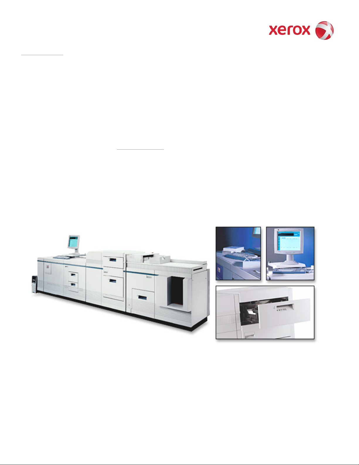
DocuTech 61xx Production Publisher Family
701P48388
February 19, 2008
Operator HandyBook
The purpose of this HandyBook is to provide a quick reference for the operator. It does not
replace the Operator Guide or other Xerox supplied reference materials.
More information is available at www.Xerox.com. The Operator Guide is available for download
as well.
Page 2

Prepared by:
Xerox Corporation BGO/PSG/PDU/Cost Productivity
800 Phillips Road, 207-02Z
Webster, New York 14580
USA
© 2008 Xerox Corporation. All rights reserved. Xerox® and the sphere of connectivity design are trademarks of
Xerox Corporation in the US and/or other countries.
Changes are periodically made to this document. Changes, technical inaccuracies, and typographic
errors will be corrected in subsequent editions
Page 3

Table of Contents
Table of Contents......................................................................3
1. System Hardware.................................................................7
Processor Components................................................................................................................ 8
Interposer Components................................................................................................................ 9
Finisher Components ................................................................................................................. 10
Paper Path Areas ....................................................................................................................... 11
2. Paper Trays & Loading Media...........................................13
Paper Tray & Finisher Capacities............................................................................................... 13
Adding Paper to Tray 1 or 2 ....................................................................................................... 16
Adding Paper to Trays 3, 4, or 5................................................................................................. 18
Loading Transparencies............................................................................................................. 19
Re-Loading Tabs........................................................................................................................ 19
Adding Inserts............................................................................................................................. 20
Satisfaction Guides..................................................................................................................... 21
Satisfaction Guide for Paper Trays 1 and 2 .................................................................. 21
Satisfaction Guide for Paper Tray 3.............................................................................. 22
Satisfaction Guide for Paper Tray 4.............................................................................. 23
Satisfaction Guide for Paper Tray 5.............................................................................. 23
Satisfaction Guide for 2-Sided Printing ......................................................................... 24
Satisfaction Guide for Various Stocks........................................................................... 24
Satisfaction Guide for Stitcher....................................................................................... 26
3. Recommended Shift Preventative Maintenance Plan ....27
4. Replacing Consumables ...................................................29
Add Fuser Agent........................................................................................................................ 29
Replace Stitcher A Wire ............................................................................................................. 31
Replace the Binder Tape Reel................................................................................................... 34
Replace the Toner (Dry Ink) Bottle.............................................................................................37
Replace the Toner (Dry Ink) Waste Container........................................................................... 38
Order Supplies, Consumables, and Parts.................................................................................. 40
5. Machine Maintenance........................................................41
Adjusting for Paper Curl ............................................................................................................. 41
Adjusting the Heavy Paper Levers............................................................................................. 44
Adjust the Binder Tape Registration........................................................................................... 46
Enable a Paper Tray for Clean up..............................................................................................47
Enable or Disable the Binder...................................................................................................... 47
Enable or Disable the Stacker....................................................................................................48
Enable or Disable the Stitcher....................................................................................................48
Modify the Bindexer Capacity Number.......................................................................................49
Modify the Lighter / Darker Setting.............................................................................................49
Stop a Job From Printing at the Printer...................................................................................... 50
6. Problem Solving.................................................................51
COMMON FAULT CODES & CASE .......................................................................................... 52
PROBLEM LISTING AND SOLUTIONS, LISTED by CASE NUMBER ..................................... 55
Solutions in Alphabetical Order.................................................................................................. 66
Clean Finisher Entrance Sensor (Q1201).................................................................................. 68
Clean the Bin A Bindexer Sensor (Q1205)................................................................................. 71
Clean the Bin B Bindexer Sensor (Q1206)................................................................................. 72
Clean the Binder Tape Guide Sensor (Q1213).......................................................................... 73
DT6180 HandyBook
Page 4

Clean the Bindexer Sensors (Q1205, Q1206, Q1207)............................................................... 74
Clean the Bins Exit Sensors (Q1222)......................................................................................... 75
Clean the Front Stack (Q1227), Rear Stack Height (Q1218), and Set Path (Q1221) Sensors. 77
Clean the Fuser (Q1010) and Prefuser Sensors (Q1009) ......................................................... 80
Clean the Post Inverter (Q1202) and Output Transport (Q1203) Sensors ................................ 82
Clean the Pre-Fuser Sensor (Q1009) ........................................................................................ 84
Clean the Registration Transport Sensor (Q861).......................................................................85
Clean the Set Path Sensor (Q1221)........................................................................................... 86
Clean the Tape Binder Area.......................................................................................................89
Clear Paper Jams in Areas 11, 12, 13, and 14 .......................................................................... 91
Clear Paper Jams in Areas 11, 12, and 13 ................................................................................ 94
Clear Paper Jams in Areas 13, 14, and 15 ................................................................................ 97
Clear Paper Jams in Areas 17 and 18 ..................................................................................... 100
Clear the Entire Paper Path From the Paper Trays to the Finisher ......................................... 102
Clear the Fault in the Printer Fault Clearance Window............................................................ 102
Clear the Paper Jam in Area 4................................................................................................. 103
Clear the Paper Jam in Areas 11, 14, 17, and 18.................................................................... 103
Clear the Paper Jam in Areas 12, 13, 14, and 15.................................................................... 107
Clear the Paper Jam in Areas 3 and 4..................................................................................... 111
Clear the Paper Jam in Areas 5 and 6..................................................................................... 112
Clear the Paper Jam in Areas 7, 6, and 5................................................................................ 113
Clear the Paper Jam in Areas 8 and 9..................................................................................... 115
Clear the Paper Jam in Areas 8, 11, 12, and 13...................................................................... 116
Clear the Paper Jams in Areas 16 and 17 ............................................................................... 119
Clear the Paper Jams in Areas 17 and 19 ............................................................................... 121
Clear the Paper Jams in Areas 7, 6, 5, 4, and 2 ...................................................................... 123
Clear the Stitcher A Fault ......................................................................................................... 125
Fan the Paper, Turn the Paper Over, and Reload ................................................................... 127
If Paper is Jammed in the Fuser, Release the Camming Motor Brake....................................127
If Printing to the Edges of the Paper Stock, set Lead Edge Screening to Stress .................... 128
If the Job is Sent From a DigiPath, Clean the Document Glass on the DigiPath..................... 129
Lower the Decurler Baffle Above Area 7.................................................................................. 129
Open and Close the Area 3 and 4 Baffles Securely................................................................. 130
Open and Close the Area 4 Baffle Securely............................................................................. 130
Open and Close the Area 9 Baffle Securely............................................................................. 131
Open and Close the Finisher Top Cover and the Finisher Front Doors................................... 131
Perform an Immediate Shutdown at the DocuSP..................................................................... 132
Power OFF, Reset the Printer Circuit Breakers, Then Power ON........................................... 132
Power OFF, Then Power ON the Printer.................................................................................. 133
Push Down on the Stacker Safety Door...................................................................................134
Read the Meter.........................................................................................................................135
Release the Camming Motor Brake......................................................................................... 135
Remove Paper From Interposer Areas B1 and B2................................................................... 137
Reset the White Power Switch................................................................................................. 138
Select Reset / Restart From the Fault Frame........................................................................... 138
Tap on the Toner (Dry Ink) Cartridge to Loosen the Toner...................................................... 139
Use A New Ream of Paper ...................................................................................................... 139
7. Perform Printer Functions...............................................141
1. Add a Font to the DocuSP Controller.................................................................................. 142
2. Allow Main, Aux, Auto, or Unspecified to be Used as Stock Names .................................. 143
3. Backup VIPP Files Before an Upgrade............................................................................... 144
4. Check the Systems Queue Output Location and Finishing Selections...............................145
5. Clear the Faulted Job.......................................................................................................... 146
6. Create a New Queue........................................................................................................... 147
7. Delete a Job in Job Manager............................................................................................... 148
DT6180 HandyBook
Page 5

8. Disable Stock Size Checking............................................................................................... 149
9. Display all Active Machine Faults........................................................................................ 150
10. Enable and Bring On-line an External Finisher................................................................. 151
8. Programming Features....................................................153
Add Binding to a Job ................................................................................................................ 153
Enable Duplex Mode................................................................................................................ 153
Enable Offset Stacking.............................................................................................................154
Export the Accounting Log ....................................................................................................... 155
Program Image Shift for a Job.................................................................................................. 156
Program Paper Tray 5 as a Non-Fusing Tray.......................................................................... 156
Program Tabs...........................................................................................................................157
Program the PCL Paper Stock Sequences to Pull From a Specific Paper Tray at the Printer 158
Uncheck the Job Ticket in Job Forwarding .............................................................................. 161
Setup Job Forwarding for Printer to Printer in DocuSP............................................................ 162
9. Sensor Maps.....................................................................165
Paper Handling Module Sensor Locations............................................................................... 165
Inverter Sensor Locations......................................................................................................... 166
Finisher Sensor Locations........................................................................................................ 167
Interposer Sensor Locations..................................................................................................... 168
DT6180 HandyBook
Page 6

System Hardware
DT6180 HandyBook 6
Page 7
System Hardware
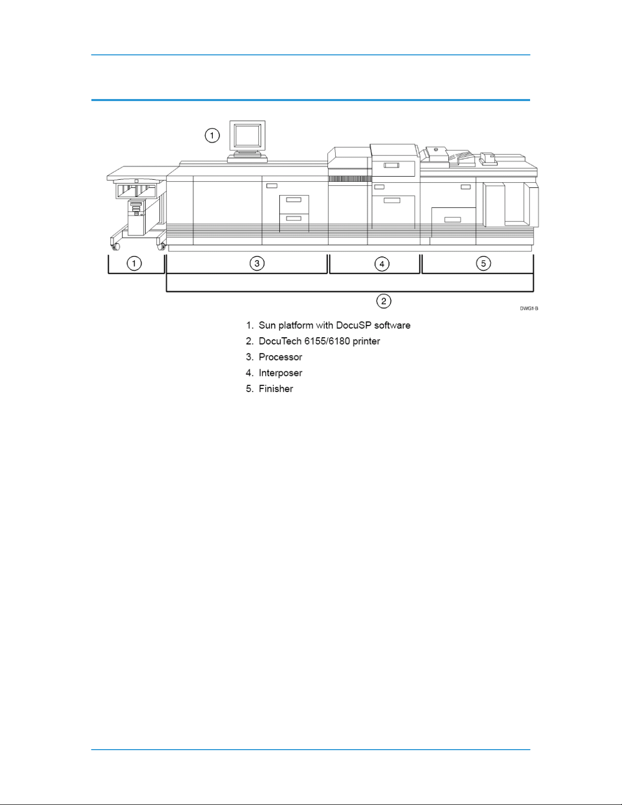
1. System Hardware
DT6180 HandyBook 7
Page 8
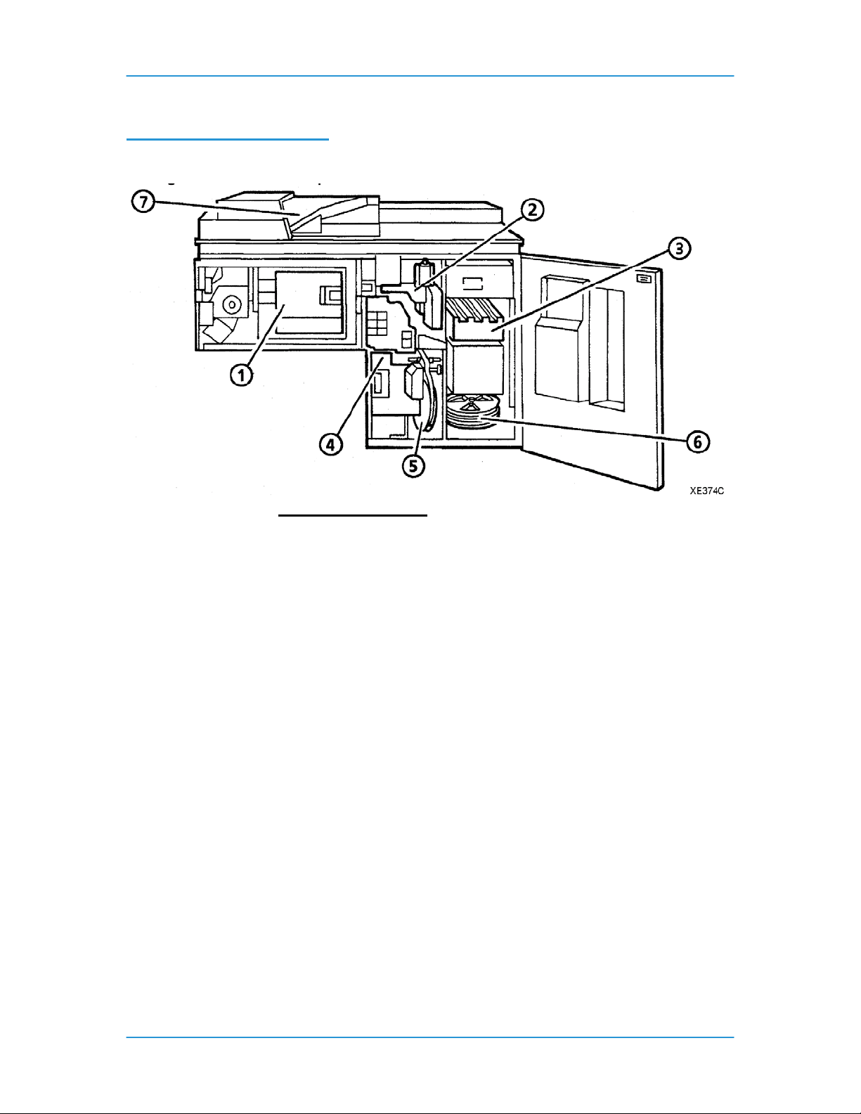
Processor Components
System Hardware
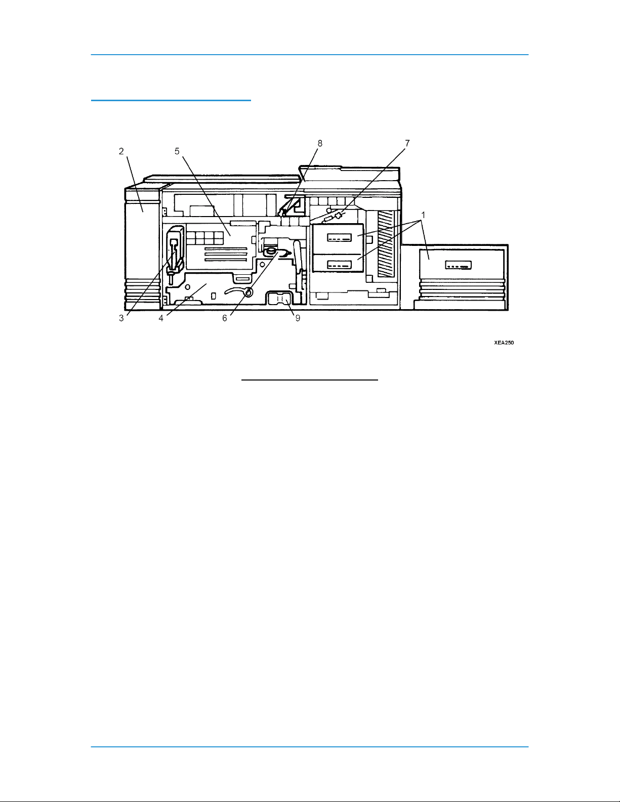
Processor Components
1. Paper trays
2. Electrical module
3. Dry ink cartridge
4. Photoreceptor, located behind a panel
5. Laser, located behind a panel
6. Fuser agent reservoir
7. Inverter
8. Decurler lever
9. Dry Ink Waste container
DT6180 HandyBook 8
Page 9
Interposer Components
System Hardware
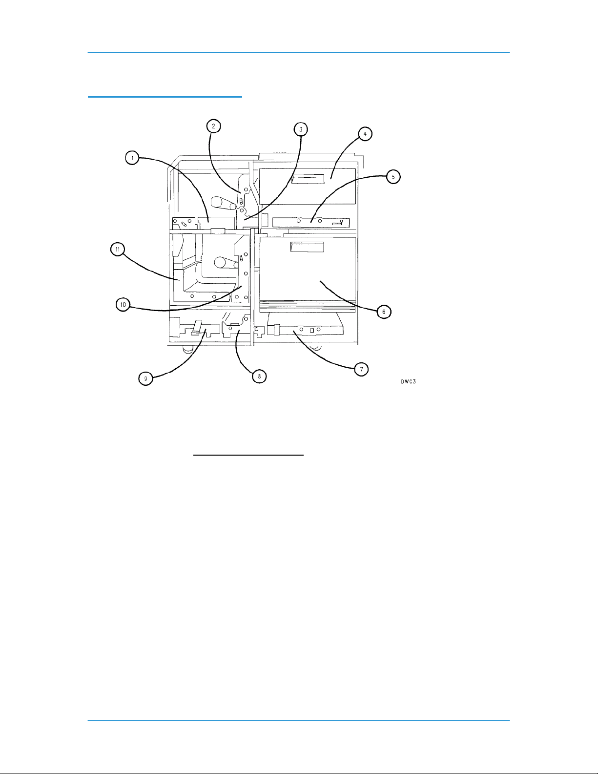
Interposer Components
1. Upper entrance transport
2. Upper vertical transport
3. Upper turn transport
4. Tray 4
5. Upper exit transport
6. Tray 5
7. Lower entrance transport
8. Lower turn transport
9. Lower exit transport
10.Lower vertical transport
11. Loop transports
DT6180 HandyBook 9
Page 10
Finisher Components
System Hardware
Finisher Components:
1. Bindexer
2. Stitcher
3. Stacker
4. Binder
5. Binder tape reel
6. Stitcher wire spools
7. Top tray
DT6180 HandyBook 10
Page 11
System Hardware
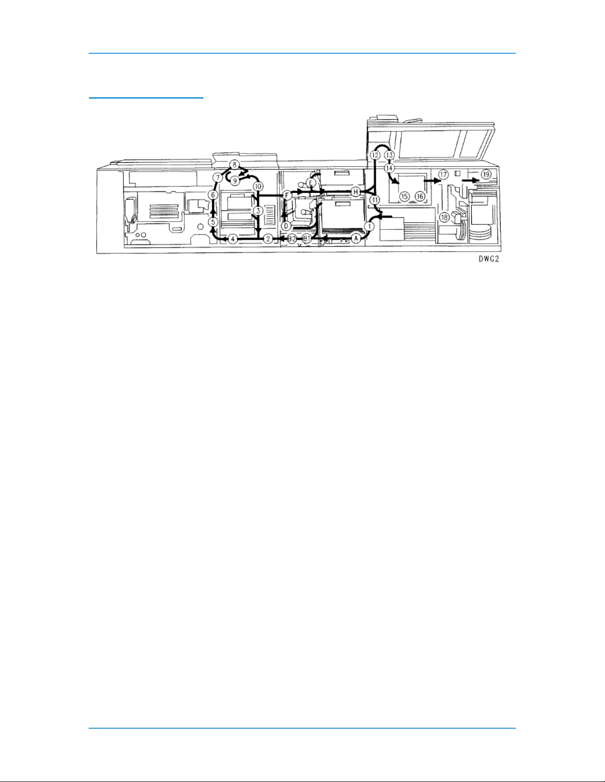
Paper Path Areas
The numbers in figure 4-6 identify the following paper path are as follows:
• Areas 1 to 4 - The stock leaves a paper tray and is fed to the photoreceptor.
• Areas 5 to 10 - The system prints an image on one side of the stock. If the job requires
2-sided printing, the system turns the page over and feeds it back to the photoreceptor.
• Areas A to H - This is the interposer area. Paper travels through this area if paper is fed
from trays 1, 4 or 5 and also to pass paper from area 10 (through F and H) to the finisher.
• Areas 11 and 12 - If the prints are to be fed to the top tray, the system delivers the prints
through the top tray slot.
• Areas 13 to 16 - The prints enter the bindexer and are collated, if desired.
• Areas 17 to 19 - The prints are stitched in area 17, or bound in area 18, if desired, and
placed on the stacker in area 19.
DT6180 HandyBook 11
Page 12

Paper Trays & Loading Media
DT6180 HandyBook 12
Page 13

Paper Trays & Loading Media
2. Paper Trays & Loading Media
Paper Tray & Finisher Capacities
Stock Weight (all trays)
Tray 1 Stock sizes
Tray 1 Capacity
Tray 2 Stock sizes
Tray 2 Capacity
Tray 3 Stock sizes
Tray 3 Capacity
Tray 4 Stock sizes
Tray 4 Capacity
DT6180 HandyBook 13
Substance 16 to 110 (60 to 200 g/m2)
• US Letter (8 1/2 x 11 inches)
• US Legal (8 1/2 X 14 inches)
• 9 x 11 inches
• A4
• 8 1/2 x 13 inches
• 223 x 297 mm
• Custom (Width = 8 to 9 inches (203 to 229 mm), Length = 10
to14 inches (254 to 356 mm))
1100 sheets, substance 20 (75 g/m2)
• US Letter (8 1/2 x 11 inches)
• US Legal (8 1/2 x 14 inches)
• 9 x 11 inches
• A4
• 8 1/2 x 13 inches
• 223 x 297 mm
• Custom (Width = 8 to 9 inches (203 to 229 mm), Length = 10 to
• 14 inches (254 to 356 mm))
600 sheets, substance 20 (75 g/m2)
• US Letter (8 1/2 x 11 inches)
• US Legal (8 1/2 x 14 inches)
• US Ledger (17 x 11 inches)
• 9 x 11 inches
• A3
• A4
• 8 1/2 x 13 inches
• 223 x 297 mm
• ISO B4
• JIS B4
• Custom (Width = 8 to 17 inches (203 to 432 mm), Length = 10
to14.33 inches (254 to 364 mm))
2600 sheets, substance 20 (75 g/m2)
• US Letter (8 1/2 x 11 inches)
• US Legal (8 1/2 x 14 inches)
• US Ledger (17 x 11 inches)
• 9 x 11 inches
• A3
• A4
• 8 1/2 x 13 inches
• 223 x 297 mm
• ISO B4
• JIS B4
• Custom (Width = 8 to 17 inches (203 to 432 mm), Length = 10
to14.33 inches (254 to 364 mm))
550 sheets, substance 20 (75 g/m2), post-process only
Page 14

Paper Trays & Loading Media
Tray 5 Stock sizes
Tray 5 Capacity
Inverter Stock sizes
Top Tray Stock Sizes
Top Tray Capacity
Stacker Stock Sizes
Stacker Capacity
Stitcher Stock Sizes
Capacity
Stitches per spool
Binder Stock sizes
Binder Capacity
Binds per spool
Bindexer Capacity
Sheets are spilling out
of the top tray
• US Letter (8 1/2 x 11 inches)
• US Legal (8 1/2 x 14 inches)
• US Ledger (17 x 11 inches)
• 9 x 11 inches
• A3
• A4
• 8 1/2 x 13 inches
• 223 x 297 mm
• ISO B4
• JIS B4
• Custom (Width = 8 to 17 inches (203 to 432 mm), Length = 10 to
• 14.33 inches (254 to 364 mm))
2600 sheets, substance 20 (75 g/m2), pre or post-process
8 x 10 inches to 17 x 11 inches (203 x 254 mm to 432 x 279 mm)
8x10 inches to 17 x 11 inches (203 x 254 mm to 432 x 279 mm)
500 sheets, substance 20 (75 g/m2)
8 x 10 inches to 9 x 14 inches (203 x 254 mm to 229 x 356 mm)
3000 sheets (1500 inboard and 1500 outboard), substance 20
(75 g/m2)
8 x 10 inches to 9 x 14 inches (203 x 254 mm to 229 x 356 mm)
See Satisfaction Guide for Stitcher
2 to 70 sheets, substance 20 (75 g/m2)
Approximately 35,000
8.5 x 11 inches (216 x 279 mm)
15 sheets (7 sheets with index covers) to 125 sheets of
substance 20 (75 g/m2) or equivalent thickness
Approximately 425
The bindexer contains three bins used by the system to sort sets.
The
capacity of each bin is 125 sheets of substance 20 (75 g/m2) or 0.5
inch
(13 mm) thickness.
Include inserts and covers when considering the output capa city of
the
bindexer.
125 sheets of substance 20 (75 g/m2) is equal to approximately:
104 sheets of substance 24 (90 g/m2)
78 sheets of substance 32 (120 g/m2)
47 sheets of substance 110 (200 g/m2).
Check that the sets in the bindexer are less than 0.5 inch (13 mm)
thick.
If the set exceeds 0.5 inch (13 mm) thickness, reprogram the job for
fewer
sheets or reduce the number of heavy-weight sheets.
When running collated, unfinished sets, the maximum sheet capacity
of the
bindexer can be set between 50 and 125.
When running anything other than collated, unfinished sets, the
maximum
sheet capacity of the bindexer will remain at 125.
The capacity of the top tray is 500 sheets of substance 20 (75 g/m2)
or 2
inches (51 mm) in height. When intermixed stock or paper heavier
DT6180 HandyBook 14
Page 15

Paper Trays & Loading Media
than
substance 20 (75 g/m2) is being run, the capacity of the top tray is
reduced.
500 sheets of substance 20 (75 g/m2) is equal to approximately:
415 sheets of substance 24 (90 g/m2)
310 sheets of substance 32 (120 g/m2)
225 sheets of substance 110 (200 g/m2)
If using any paper heavier than substance 20 (75 g/m2) or
intermixed stock
of different weights, unload the top tray before the count in the tray
reaches
its capacity limit.
Refer to the satisfaction guides in the "Technical information"
chapter.
DT6180 HandyBook 15
Page 16
Paper Trays & Loading Media
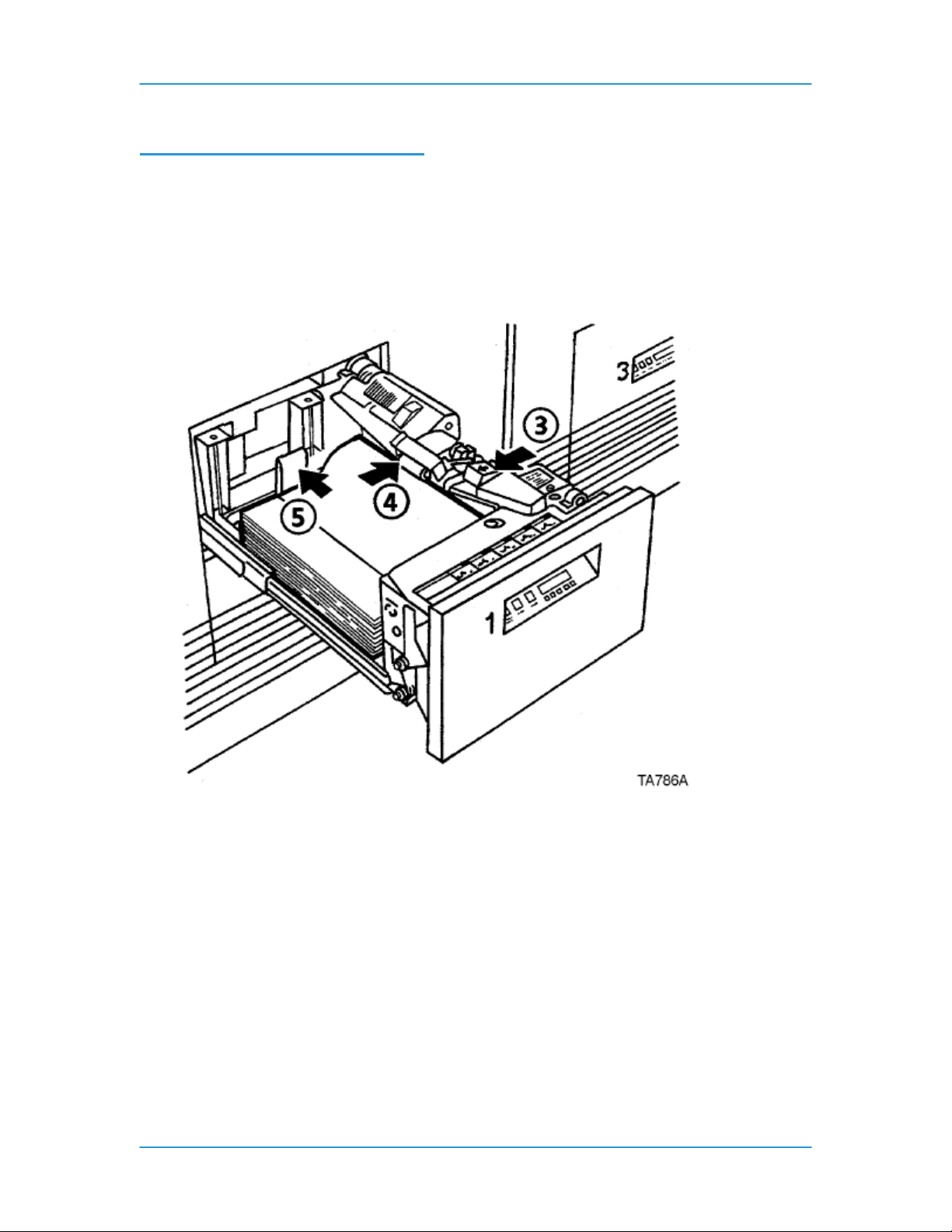
Adding Paper to Tray 1 or 2
The following steps must be performed to add paper to tray 1 or 2.
1. Press the Tray unlock button on the front of the tray. Wait for the red "Please wait" light to
go off.
2. When the green "Ready to open" light comes on, pull the tray out until it stops.
3. Press the green release tab.
4. Lift the metal handle on the feed belt and remove any paper under the belt.
5. Move the rear guide to the back of the tray.
NOTE: To load the paper correctly, refer to the label located
on the inside panel at the front of the paper tray. Remove any
damaged sheets from the top of the stack.
Do not load the paper above the red line. A jam could occur if too
much paper is loaded in the tray.
6. Load the required paper into the paper tray. Load paper with the curl side facing down.
Load Xerox paper with the package wrapper seam side facing up.
NOTE: When loading drilled paper, be sure to fan the edge where the holes are
located.
7. Position the stack against the front right corner of the tray, as shown below. This is
indicated by the green arrow on the bottom of the tray.
DT6180 HandyBook 16
Page 17
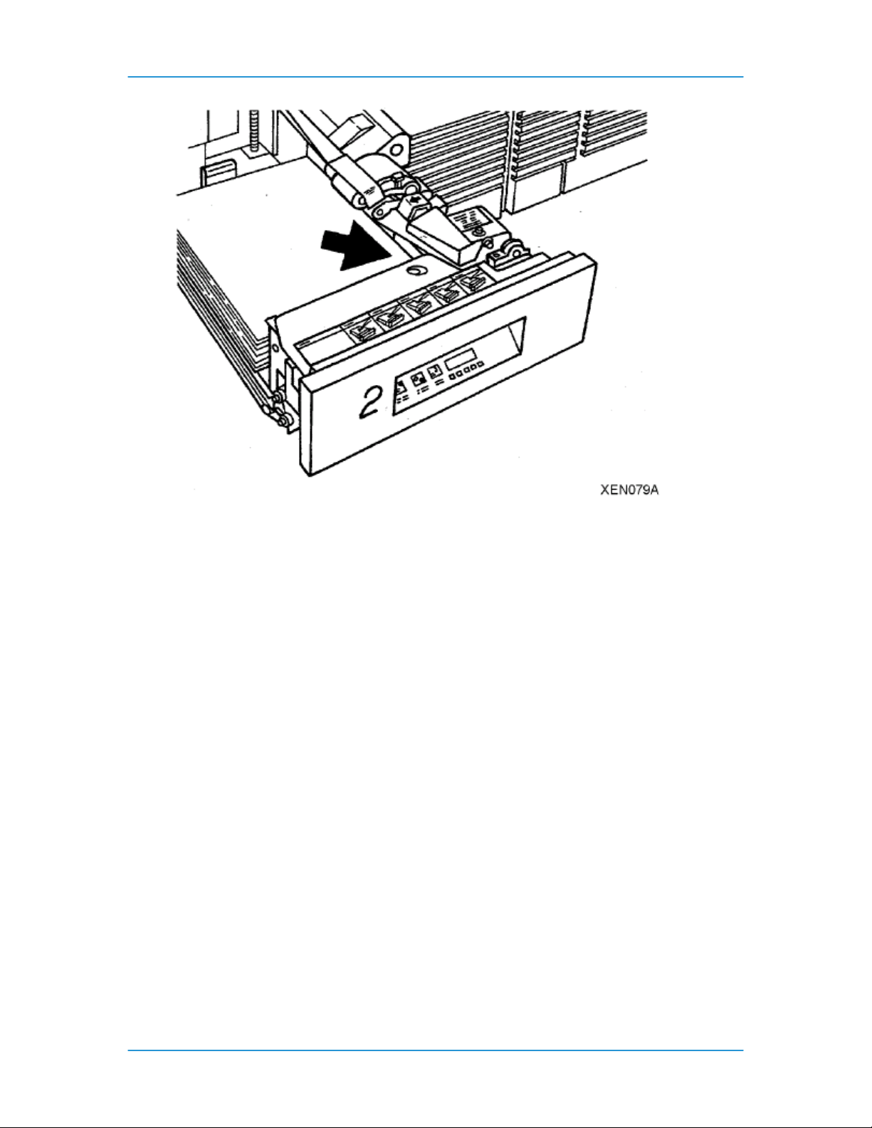
Paper Trays & Loading Media
Move the rear guide forward until it touches the edge of the stack.
Lower the feed belt.
Close the tray slowly, but firmly, until it latches.
DT6180 HandyBook 17
Page 18
Paper Trays & Loading Media
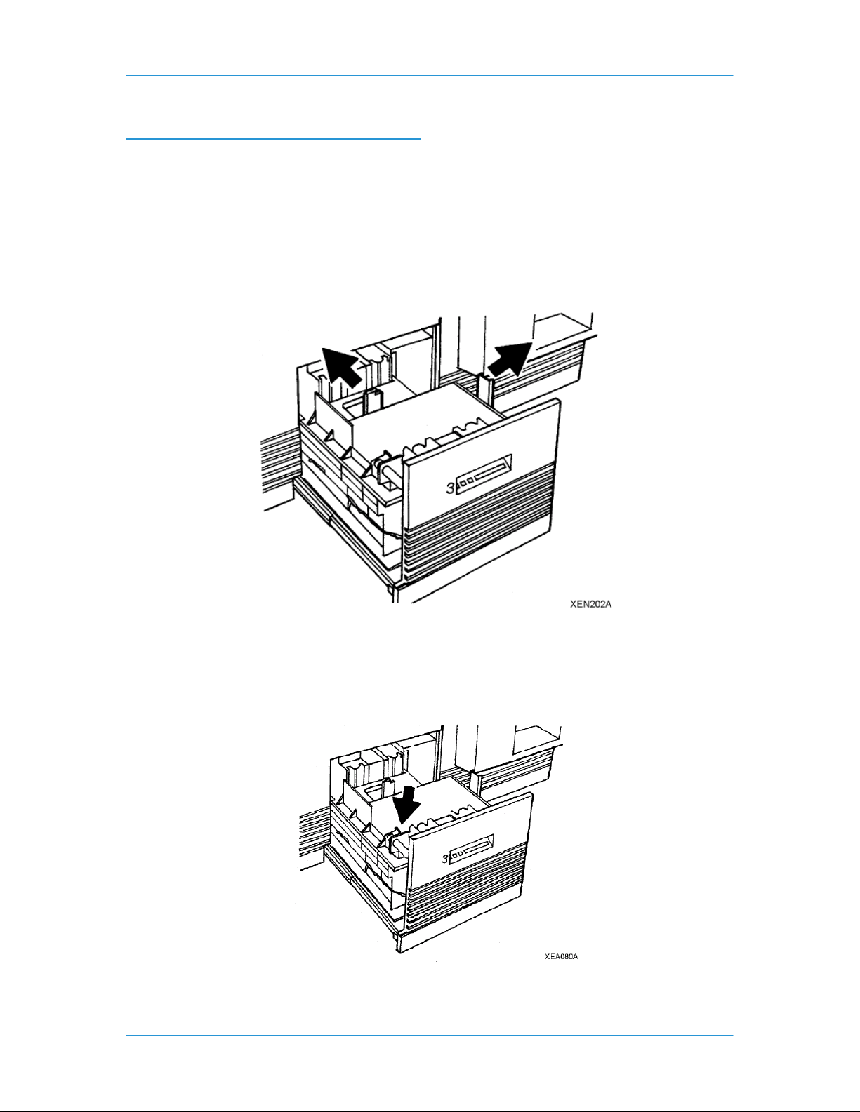
Adding Paper to Trays 3, 4, or 5
1. Press the Tray unlock button on the front of the tray. Wait for the red "Please wait" light to
go off.
NOTE: If the tray is not pulled out all of the way, the tray elevator will not go down as
paper is added.
2. When the green "Ready to open" light comes on, pull the tray out until it stops.
3. Move the rear and side guides away from the paper stack, as shown below.
4. Load the required paper into the paper tray. Load paper with the curl side facing down.
Load Xerox paper with the package wrapper seam side facing up.
NOTE: When loading drilled paper, be sure to fan the edge where the holes are located.
5. Position the stack against the front left corner of the tray, as shown below. This is
indicated by the green arrow on the bottom of the tray.
6. Move the rear and side guides until they touch the paper stack.
7. Close the tray slowly, but firmly, until it latches.
DT6180 HandyBook 18
Page 19

Paper Trays & Loading Media
Loading Transparencies
The following are the different types and usage of transparencies for Paper Trays 1, 2 and 3.
• Transparencies with a 13 mm (0.5 inch) white stripe should be loaded with the white
stripe to the right if you are using Paper Trays 1 and 2. Load the shiny side up for
optimum performance.
• Removable stripe transparencies: Do not load more than 50 removable-stripe
transparencies into Paper Trays 1 and 2. With the white stripe to the right, place the
transparencies on top of approximately 50 sheets of paper in the tray. Do not run as
inserts to a bound job. Printing is not allowed on inserts.
• High speed transparencies with paper backing: Run these types of transparencies from
Paper Trays 1 and 2 with the paper side down, and from Paper Tray 3 with the paper
side up.
Re-Loading Tabs
For DocuSP version 3.X or higher:
There are two methods to replenish tab stock in the paper trays.
Option 1:
1. Open the paper tray where the tab stock is loaded.
2. Remove any tabs so that there is a full bank of tabs on top of the stack.
3. Add additional tab stock.
4. Close the paper tray.
Option 2:
1. Open the paper tray where the tab stock is loaded.
2. Add additional tab stock to the bottom of stack.
3. From the DocuSP for DocuTech 2000 series 61XX screen, select [Printer Manager].
Information about each paper tray will be displayed.
4. Select the line that has the information about the paper tray you are adding tab stock to.
A menu will be displayed.
5. Select [Properties] from the menu. The Tray Properties window will be displayed.
6. Select the check box next to [Set Sequence Position]. The box below the Set Sequence
Position box will become active.
7. Enter the number of tabs remaining in the bank of tabs on top of the stack in the paper
tray. For example, if there are three tabs remaining on top of the stack in the tray, enter
the number [3] in this box.
8. Select the check box next to [Check Override Programming] in the lower, left corner of
the window.
9. Select [OK].
10. Close the paper tray.
For DocuSP version 2.X or lower:
1. Open the paper tray where the tab stock is loaded.
2. Remove any tabs so that there is a full bank on top of the stack.
3. Add additional tab stock.
4. Close the paper tray.
DT6180 HandyBook 19
Page 20

Paper Trays & Loading Media
Adding Inserts
For DocuSP 4.x and above:
Creating inserts differs from slip sheets in that they separate pages of a job while slip sheets
separate one job from another. Inserts may also be pre-printed stock or forms.
NOTE: Inserts may not be programmed for a job with covers if the inserts affect the cover
printing. For example, inserts are not allowed between pages printed on the front and back of a
cover. An insert request takes precedence over an exception page request. When two or more
special pages are programmed (covers, inserts, or exception pages) image ordering conflict s may
occur. Make sure that programmed options do not conflict.
1. From the DocuSP screen, logon as a System Administrator. See the Related Items
below for additional information.
2. Under Managers on the left, under the Job button, right-click on your job and select
[Properties] from the menu.
3. Click on the [Special Pages] tab.
4. Click on the [Inserts] button, and then click on [Add Inserts] button. The Insert screen will
be displayed.
5. If the insert is to be the first page, enter 0 (zero) in the After Pages field, and then the
number of inserts required in the Pages field. The result will be the insert being the first
page in the job.
6. Click on the [Add Insert] button.
7. Click on [Close].
8. Click [OK].
DT6180 HandyBook 20
Page 21

Satisfaction Guides
Satisfaction Guide for Paper Trays 1 and 2
Stock Reliable feeds may be
expected
Size 8 x 10 inches to 9 x 14
inches (203 x 254 mm to
229 x 356 mm)
Weight Substance 20 to 110 (75 to
200 g/m2)
Capacity Tray 1 - 1100 sheets,
substance 20 (75 g/m2)
Tray 2 - 600 sheets,
substance 20 (75 g/m2)
Type or
condition
Xerographic bond paper in
good condition
Drilled stock, fanned
thoroughly
Tab stock in perfectly flat
condition
Less reliable feeds may be
expected
Stock smaller than 8 x 10
Substance 16 to 19 (60 to 72
g/m2)
For greater capacity, use
Slightly curled paper
Intermixed weights
Transparencies
Label stock
Adhesive drafting film
Paper with reinforced edges
Paper Trays & Loading Media
Suggested alternatives
inches cannot be used.
For stock larger than 9 x 14
inches (229 x 356 mm), refer
to the tray 3 satisfaction
guide.
Weights outside the limits
shown are not
recommended.
Substance 110 (200 g/m2)
must be long grain. Do not
use short grain.
Tray 3.
Do not use excessively
curled paper
Substance 110 (200 g/m2)
must be long grain. Do not
use short grain.
Use transparencies with a
white stripe.
Freshly printed offset prints,
use tray 3.
Refer to the “Using various
stocks” section for any stock
not defined in this guide.
DT6180 HandyBook 21
Page 22

Satisfaction Guide for Paper Tray 3
Stock Reliable feeds may be
expected
Size 8 x 10 inches to 17 x 11
inches (203 x 254 mm to
432 x 279 mm)
Weight Substance 16 to 110 (60 to
200 g/m2)
Capacity 2600 sheets, substance
20 (75 g/m2)
Type or
condition
Xerographic bond paper in
good condition
Drilled stock, fanned
thoroughly
Less reliable feeds may be
expected
Smaller or larger sizes
Weights outside the limits
Slightly curled paper
Intermixed weights
Xerox vellum
Full cut tabs
Label stock
Adhesive drafting film
Paper with reinforced edges
Paper Trays & Loading Media
Suggested alternatives
cannot be used.
shown are not
recommended.
Substance 110 (200 g/m2)
must be long grain except 17
x 11 inch (432 x 279 mm)
substance 110 (200 g/m2)
which must be short grain.
Do not use excessively
curled paper
Substance 110 (200 g/m2)
must be long grain. Do not
use short grain.
Precut tabs - use tray 1 or 2.
Transparencies with a white
stripe, use tray 1 or 2.
Freshly printed offset prints,
use tray 3.
Refer to the “Using various
stocks” section for any stock
not defined in this guide.
DT6180 HandyBook 22
Page 23

Satisfaction Guide for Paper Tray 4
Stock Reliable feeds may be
expected
Size 8 x 10 inches to 17 x 11
inches (203 x 254 mm to
432 x 279 mm)
Weight Substance 16 to 110 (60 to
200 g/m2)
Capacity 550 sheets, substance 20
(75 g/m2)
Type or
condition
Xerographic bond paper in
good condition
Drilled stock, fanned
thoroughly
Less reliable feeds may be
expected
Smaller or larger sizes
Weights outside the limits
Slightly curled paper
Intermixed weights
Xerox vellum
Full cut tabs
Label stock
Adhesive drafting film
Paper with reinforced edges
Paper Trays & Loading Media
Suggested alternatives
cannot be used.
shown are not
recommended.
Substance 110 (200 g/m2)
must be long grain except 17
x 11 inch (432 x 279 mm)
substance 110 (200 g/m2)
which must be short grain.
Do not use excessively
curled paper
Substance 110 (200 g/m2)
must be long grain. Do not
use short grain.
Refer to the “Using various
stocks” section for any stock
not defined in this guide.
Satisfaction Guide for Paper Tray 5
Stock Reliable feeds may be
expected
Size 8 x 10 inches to 17 x 11
inches (203 x 254 mm to
432 x 279 mm)
Weight Substance 16 to 110 (60 to
200 g/m2)
Capacity 2600 sheets, substance
20 (75 g/m2)
Type or
condition
Xerographic bond paper in
good condition
Drilled stock, fanned
thoroughly
DT6180 HandyBook 23
Less reliable feeds may be
expected
Suggested alternatives
Smaller or larger sizes
cannot be used.
Weights outside the limits
shown are not
recommended.
Substance 110 (200 g/m2)
must be long grain except 17
x 11 inch (432 x 279 mm)
substance 110 (200 g/m2)
which must be short grain.
Slightly curled paper
Intermixed weights
Xerox vellum
Full cut tabs
Label stock
Adhesive drafting film
Do not use excessively
curled paper
Substance 110 (200 g/m2)
must be long grain. Do not
use short grain.
Refer to the “Using various
stocks” section for any stock
not defined in this guide.
Paper with reinforced edges
Page 24

Paper Trays & Loading Media
Satisfaction Guide for 2-Sided Printing
Stock Reliable feeds may be
expected
Size 8 x 10 inches to 17 x 11
inches (203 x 254 mm to
432 x 279 mm)
Weight Substance 16 to 110 (60 to
200 g/m2)
Substance 110 (200 g/m2)
must be long grain.
Type or
condition
Xerographic bond paper in
good condition
Drilled stock, fanned
thoroughly
Less reliable feeds may be
expected
Suggested alternatives
17 x 11 inch (432 x 279 mm)
paper can only be sent to
the top tray.
Weights outside the limits
shown are not
recommended.
Slightly curled paper
Paper with reinforced edges
Do not use excessively
curled paper
Refer to the “Using various
stocks” section for any stock
not defined in this guide.
Satisfaction Guide for Various Stocks
Stock type Instructions for use
• Recycled Paper
• Substance 13 (49 g/m2) paper
• Substance 16 (60 g/m2) paper
• Substance 20 (75 g/m2) paper
• Card stock
• Xerox substance 65 (176 g/m2)
• Substance 110 (200 g/m2) long grain
(index)
• Xerox 4024, substance 20 (75 g/m2)
• 3 hole drilled
• 4 hole drilled
• 7 hole drilled
• Never-tear, 3 hole drilled
DT6180 HandyBook 24
Acceptable, but may increase paper dust
contamination problems in machine. Recommend
vacuum paper before installing in machine to
minimize paper dust.
Use trays 3,4,or 5.
Do not run 2-sided prints.
Load the paper with seam side down into tray 3.
Optimum satisfaction can be expected with 8.5 x
11 inch (216 x 279 mm) or larger paper.
Load paper with seam side up into trays 1 and 2;
seam side down into tray 3, 4, or 5.
Optimum satisfaction can be expected from tray
3, 4, or 5.
Load the paper with seam side up into trays 1
and 2; seam side down into trays 3, 4, and 5.
Card stock can be run from any tray.
Reduce set size if frequent paper jams or
bindexer jams occur. If collated unfinished,
another solution is to lower the value of the
bindexer capacity set in the SWITCHES mode.
Load the paper into trays 1 and 2 with holes to
the right; load the paper into trays 3, 4, and 5 with
holes to the left.
Use the Image Shift or Reduce/Enlarge options
to avoid printing near the holes.
Fan the paper and check the paper for loose
paper plugs before loading the paper into the
trays.
Load the paper into trays 1 and 2 with holes to
the right; load the paper into trays 3, 4, and 5 with
Page 25

Paper Trays & Loading Media
Stock type Instructions for use
holes to the left.
Do not bind or run 2-sided prints.
• Never-tear
• 3 hole drilled, edge reinforced, 4024 DP
paper
• Transparencies with a 0.5 inch (13 mm)
white stripe
• Removable stripe
• Transparencies
• Tabs
• Preprinted stock
• High speed
• transparencies with white
• stripe
• Label stock
• Letterhead (preprinted)
DT6180 HandyBook 25
Do not bind or run 2-sided prints.
Do not stitch or bind. Do not run with tabs. Tabs
can be inserted off-line.
For optimum satisfaction, use the paper trays 1
and 2 plate assembly. The plate assembly can be
ordered by a Customer Service Representative.
Up to 500 sheets can be placed in the tray.
Load the paper into all trays with holes to the left,
reinforced side down.
Select Properties... on the Trays pull-down
menu. On the Stock window, under Type, select
Drilled.
Image quality problems may occur near the
reinforcement with side 2 printing.
Remove the paper immediately before use to
ensure that prints stay flat.
Print with no more than 200 sheets in a tray.
Select a quantity of 50 or fewer at a time.
Load the stock with the white stripe to the right
into trays 1 and 2.
Load the shiny side up for optimum performance.
Do not load more than 50 removable-stripe
transparencies into trays 1 and 2.
With the white stripe to the right, place the
transparencies on top of approximately 50 sheets
of paper in the tray.
Do not run as inserts to a bound job. Printing is
not allowed on inserts.
Mylar tabs should be run out of tray 4.
Preprinted forms must be made up of ink that has
the following characteristics:
• Can withstand temperatures up to 400°F
(204°C)
• Can withstand pressure of 140 psi at the
above temperature
• Can withstand the above conditions for 25
Milliseconds
Load the stock with the stripe to the right in trays
1 and 2.
Load the stock face up into trays 1 and 2; face
down into trays 3, 4, and 5.
Do not select 2-sided prints.
Load the paper into trays 3, 4, and 5; side 1 with
the printed side down, top edge to the front of the
tray.
Page 26

Paper Trays & Loading Media
Stock type Instructions for use
Load the paper into trays 1 and 2; side 1 up with
the top edge to the front of the tray.
Do not use freshly preprinted paper in trays 1 and
2.
• Textured paper
• Window stock
• Xerox Carbonless
Do not use the following stocks:
• Multipart forms
• Stocks outside of the recommended size and weight ranges
Heavily textured paper may produce prints with a
ragged character appearance or deletions. To
test, run a proof print.
Run if the window is 2.2 to 4 inches (57 to 102
mm) from the top edge of the paper and at least 1
inch (25.4 mm) from each side of the paper.
Run only as the first page or a front cover to
avoid finisher bin jams.
Load the window stock face-up into a tray (tray 1
or 2 is recommended) with the top edge toward
the front of the tray.
If running plastic-covered window stock, there
may be some distortion. To test, run a proof copy.
Xerox Carbonless Paper is recommended.
Satisfaction Guide for Stitcher
The specifications for stock fed to the Stitcher for reliable stapling are as follows:
Size:
Weight:
NOTE: For larger sizes, send to Top Tray as Unstapled.
Set size limit due to copy paper weight:
203 mm x 254 mm to 229 mm x 356 mm 8 x 10 inches to 9 x 14.33 inches
- Weights outside the above limits are not
Metric Imperial
60 g/m² to 200 g/m²
recommended.
16 to 110 index / 53 bond or xerographic
- Weights outside the above limits are not
recommended.
• Collated: Up to 65 sheets of 80 g/m² (20 lb), or 7 mm (0.28 inch) thick sets. Less reliable stapling
may be expected from 66 to 70 sheets.
• Uncollated: 50 sheets maximum per stitch, 7 mm (0.28 inch) thick sets. Minimum: 2 sheets.
Type or condition: Xerographic bond paper in good condition, and drilled or hole-punched paper. The
Stacker capacity adjusts automatically to suit various set sizes.
DT6180 HandyBook 26
Page 27

Recommended Shift Preventative Maintenance Plan
3. Recommended Shift Preventa tive Maintenance Plan
Regular operator maintenance of your equipment is likely to improve overall
performance. The maintenance could be done at the beginning or end of the
shift, which ever is decided upon by your team. The following are suggested
maintenance activities.
1. Clean All Sensors.
2. Full Shutdown and Restart.
3. Check and Fill Fuser Agent.
4. Shift handoff communication between operators regarding system issues
encountered on previous shift.
5. Clean Dicorotron Shields (NOTE: Only perform this task if you have been
eXcellerate Trained. Refer to your eXcellerate training materials for
details.)
Shift preventative Maintenance Plan Details
1. Clean All Sensors.
Clean Finisher Entrance Sensor (Q1201)
Clean the Bin A Bindexer Sensor (Q1205)
Clean the Bin B Bindexer Sensor (Q1206)
Clean the Binder Tape Guide Sensor (Q1213)
Clean the Bindexer Sensors (Q1205, Q1206, Q1207)
Clean the Bins Exit Sensors (Q1222)Error! Bookmark not defined.
Clean the Front Stack (Q1227), Rear Stack Height (Q1218), and Set Path (Q1221)
Sensors
Clean the Fuser (Q1010) and Prefuser Sensors (Q1009)
Clean the Post Inverter (Q1202) and Output Transport (Q1203) Sensors
Clean the Pre-Fuser Sensor (Q1009)
Clean the Registration Transport Sensor (Q861)
Clean the Set Path Sensor (Q1221)
Clean the Tape Binder Area
DT6180 HandyBook 27
Page 28

Recommended Shift Preventative Maintenance Plan
2. Shut Down, Then Start Up the System, Then Power On the Printer
WARNING: Powering OFF the System, and thus the printer will result in the loss of all jobs in the
print queue. Under normal operating conditions, use the DocuSP Controller software to power OFF
the machine.
NOTE: If jobs are currently printing or waiting to print, they should be placed on hold before you power OFF
the System and the printer. You must be logged on as a System Administrator or Trusted User to place a job
on hold.
To Shut Down and Start Up the System:
1. Make sure that the “System Administrator” is logged in on the machine.
2. In the DocuSP [System Menu], on the walk up dialog frame, select [Shutdown].
3. Select the [Yes] confirmation button.
4. Allow the system to shut down.
5. In the Solaris command line type [boot] and hit the [return] key.
6. Ignore the various messages displayed on the monitor as the machine boots up.
To power ON the printer:
1. Make sure that the “System Administrator” is logged in on the machine.
2. In the Print Manager window, select [Printer] from the toolbar. A menu will be displayed.
3. Select [Printer On] from the menu.
The printer that your Controller is attached to will be powered ON. This process will happen without a
confirmation window.
3. Check and Fill Fuser Agent. See
4. Replacing Consumables: Add Fuser Agent page 27.
4. Shift handoff communication between operators regarding system
issues encountered on previous shift.
5. Clean Dicorotron Shields (NOTE: Only perform this task if you
have been eXcellerate Trained. Refer to your eXcellerate training
materials for details.)
DT6180 HandyBook 28
Page 29

Replacing Consumables
4. Replacing Consumables
Add Fuser Agent
NOTE: You should add Fuser Agent as soon as possible after the message is displayed. If Fuser
Agent is not added the machine will stop running after approximately 5,000 prints and will not run
until Fuser Agent is added.
To add Fuser Agent:
1. Open the Processor Doors.
2. Place a drop cloth on the floor under the Fuser area to catch any Fuser Agent that may
spill.
WARNING: The Fuser area can reach temperatures of approximately 425 ° F / 218 °
C. Use extreme care to prevent burns when working in this area.
3. Grasp the green handle and lift up to open the Fuser Drawer.
4. Pull the Fuser Drawer all the way out of the machine until it stops.
WARNING: Fuser Agent contains silicone which can cause irritation upon contact
with the eye. Use latex gloves if you have them or make sure that you wash your
hands with soap and water after you finish this procedure.
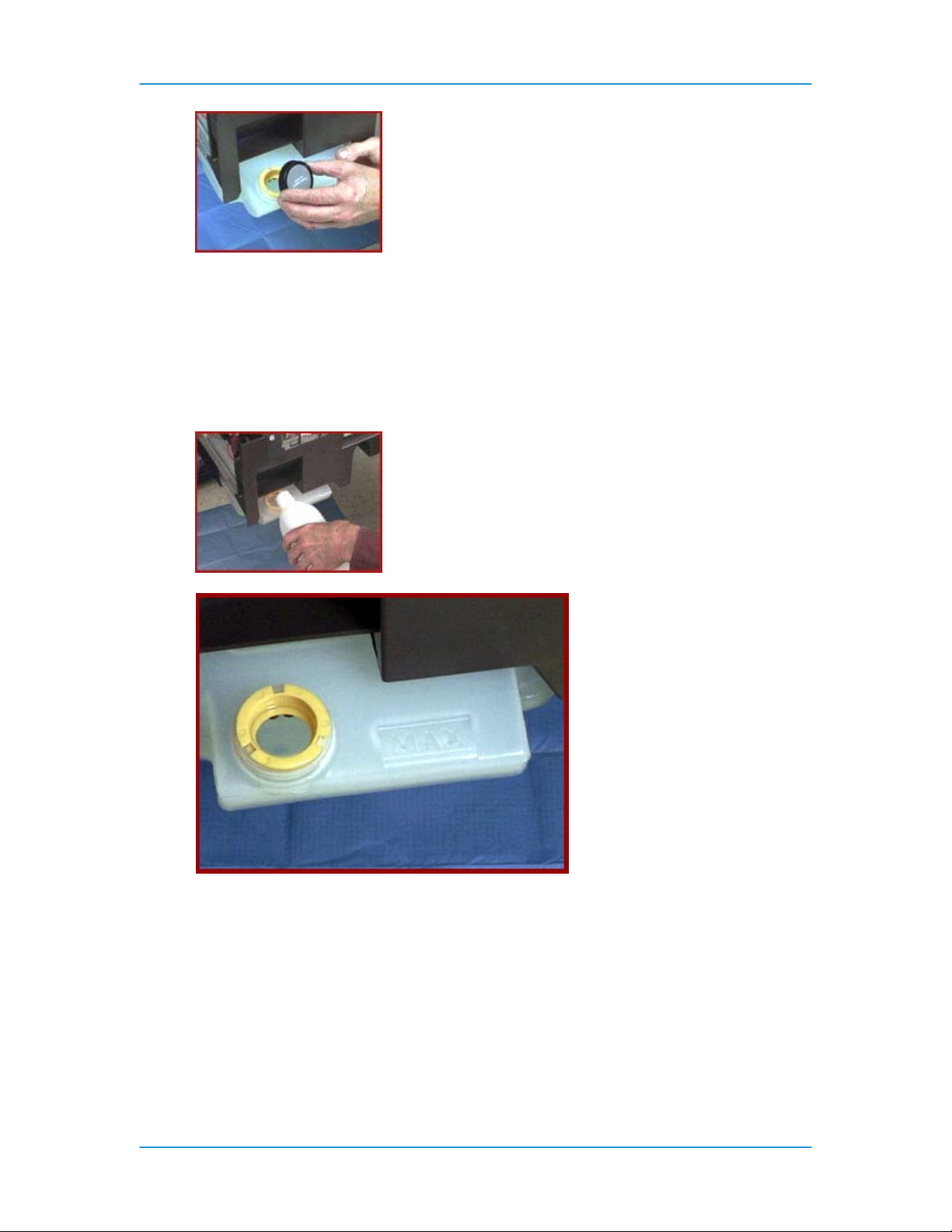
5. Pull the Fuser Agent reservoir out until it stops.
6. Remove the reservoir cap.
DT6180 HandyBook 29
Page 30
Replacing Consumables
7. Open a new box of Fuser Agent and remove the bottle.
CAUTION: Make sure you use the Fuser Agent specific to the machine model y ou
are using. Fuser Agent for the machine model DocuTech 90 is not compatible with
the DocuTech 135.
8. Remove the cap from the bottle of the Fuser Agent.
9. Carefully pour the Fuser Agent into the reservoir until the level reaches the Max line.
CAUTION: There is an anti-splash seal in the reservoir. To avoid damage to this
seal, do not push the Fuser Agent bottle into the reservoir with excessive force.
WARNING: If any Fuser Agent is spilled onto the floor, it must be removed
immediately as the floor can become slippery.
10. Replace the reservoir cap.
11. Push the Fuser Agent reservoir in to the machine until it stops.
12. Push the Fuser Drawer all the way into the machine until the drawer latches into place.
13. Close the Processor Doors. The Fuser Agent message will disappear after approximately
20 prints are made.
DT6180 HandyBook 30
Page 31

Replacing Consumables
Replace Stitcher A Wire
NOTE: You will need wire cutters to perform this procedure. Wire cutters can be found next to
Stitcher Spool B.
1. Open the Finisher Doors.
2. Raise the Stitcher Panel. The Stitcher Panel is a black plate about 228 mm (9 inches)
square. Lift the panel out from the bottom and then up. When flipped out and up, the
panel has a series of pictures that provide instructions on how to change Stitcher A Wire.
3. Pull the green Stitcher Head Release Handle forward and up. The handle is above and to
the left of the Stitcher spools.
NOTE: If the spool is empty, skip to step 5; otherwise, continue with step 4.
4. If any wire remains on the spool, carefully rewind the wire out of the plastic tubing onto
the spool.
5. Locate the Stitcher wire plug. The plug is located behind the right Finisher Door and has
a white plastic tube leading up to it. The plug itself is a larger black tube about 38 mm
(1.5 inches) in length.
6. Press down on the release clip. The release clip is a small semi-circle shaped silver clip.
NOTE: If you rewound the wire onto the spool in step 4, then step 7 is not necessary.
7. Pull the Stitcher wire plug out of the Stitcher Head.
CAUTION: Be careful when you pull the wire out of the plastic tubing. The wire can
spring out and hit you if the wire is pulled rapidly.
DT6180 HandyBook 31
Page 32

Replacing Consumables
f
8. Use the wire cutters to pull the remaining wire out of the plastic tubing.
9. Place the Stitcher plug in the measuring bracket. The measuring bracket is a black metal
plate about 25 mm (1 inch) in length, with a hole in it that the stitcher plug fits into. The
bracket is located about 51 mm (2 inches) to the right of where the Stitcher plug was
removed.
10. Locate the green Pin Release Handle under Stitcher Spool B. Pull the handle forward
and hold it in this position.
11. Pull the gold colored pin in the center of the Stitcher Wire Spool straight up.
12. Remove Stitcher Spool A.
13. Slide the new Stitcher Spool into position.
14. Reinstall the Stitcher Spool Pin. Push the pin down until it locks into place.
15. Grasp the end of the wire on the new spool.
WARNING: When the wire is cut, the cut piece may become airborne or cause the
wire on the spool to de-spool, leaving it very tangled. Hold the piece that is being
cut off to prevent projection or tangling.
16. Carefully clip the lead edge of the wire with the wire cutters. Make sure to remove any
bent or twisted wire.
17. Hold the end of the wire with the thumb and forefinger of each hand. Slowly feed the wire
into the plastic tubing until the wire extends from the Stitcher plug. Continue to feed the
wire until the wire hits the backplate of the measuring bracket.
18. Remove the Stitcher plug from the measuring bracket.
19. Use the wire cutters to remove any bent wire in the plastic tubing, and slowly pull
approximately 610 mm (24 inches) of wire out of the Stitcher plug.
20. Use the wire cutters to carefully cut the wire and leave approximately 51 mm (2 inches) o
wire extending from the Stitcher plug.
DT6180 HandyBook 32
Page 33

Replacing Consumables
>
21. Re-insert the plug into the Stitcher Head. The plug will snap itself into place if installed
correctly.
22. Push the green Stitcher Head Release Handle down and back.
23. Lower the Stitcher Panel.
24. Close the Finisher Doors.
DT6180 HandyBook 33
Page 34

Replace the Binder Tape Reel
1. Open the Finisher Doors.
Replacing Consumables
2. Grasp the green handle on the Binder assembly and pull the drawer out until it stops. The
green handle is to the right of Paper Tray 3.
WARNING: All areas of the Binder assembly, including the Binder tape, are hot
(approximately 425 °F / 218 °C). Be very careful when working in this area.
3. Raise the handle on the pressure roll and remove the Binder tape from the drive roll. The
handle is located on the upper right side of the Binder assembly.
4. Rewind the Binder tape onto the tape reel.
5. Move the reel retainer, located on the end of the tape reel spindle, to the horizontal or
unlocked position. The reel retainer is a flat metal piece that pivots on the end of the tape
reel spindle.
DT6180 HandyBook 34
Page 35

Replacing Consumables
6. Remove the tape reel.
7. Slide the new tape reel onto the tape reel drive. Make sure that the larger hole in the
center of the tape reel faces the tape reel drive.
8. If necessary, rotate the tape reel slightly until it clicks into position.
9. Move the reel retainer to the vertical, or locked position.
NOTE: Tape feed problems can result if the reel retainer is not in the locked position.
10. Thread the tape around the spools following the instructions on the Binder tape loading
label which is located to the left of the Binder tape reel.
11. Thread the tape around the drive roll to the edge of the pressure roll.
NOTE: Make sure the tape is threaded correctly. As it comes off the reel and over the
first pulley, it must go through the sensor. If the tape is not threaded correctly, the
message will not go away.
12. Turn the green knob to the right until the tape is at least 51 mm (2 inches) beyond the
tape guides.
DT6180 HandyBook 35
Page 36

Replacing Consumables
NOTE: If a problem occurs when you are trying to turn the green knob, close the Finisher
Doors. The Screen will display a 'Please wait - Finisher Reset in Progress' message.
Wait until a 'Ready' message is displayed, then open the Finisher Doors and try feeding
the Binder tape again.
13. Cut the tape by lifting up on the green tape cutter handle located on the left side of the
Binder assembly. Lift up the handle to manually cut the tape and then release the handle.
14. Remove the cut piece of tape.
15. Push the Binder drawer in until it stops.
16. Close the Finisher Doors.
For the highest quality performance, occasionally check the Binder tape length and adjust, if
necessary.
DT6180 HandyBook 36
Page 37

Replacing Consumables
Replace the Toner (Dry Ink) Bottle
CAUTION: Do not use warm water or cleaning solvents to remove Toner from your skin or
clothing. This will set the Toner and make it difficult to remove. If Toner gets on your skin
or clothing, use a brush to remove the Toner, blow it off, or wash it off with cold water and
mild soap.
NOTE: There is an eight step diagram to the right of the Toner Bottle with instructions on how to
change the cartridge.
To remove the Toner (Dry Ink) Bottle:
1. Open the Processor Doors.
2. Place a drop cloth or a few sheets of paper on the floor under the Toner Bottle area to
catch any Toner that may spill on the flooring.
3. Pull the empty Toner Bottle out of the machine until it stops.
4. Rotate the green handle up, to the unlatched position.
5. Remove the bottle from the receptacle.
NOTE: You may want to put the used Toner Bottle in the box that the new cartridge came
in. Empty Toner Bottles are not returned to Xerox and can be disposed of according to
your local recycling regulations.
To replace the Toner Bottle:
6. Remove the new Toner Bottle from the box. Make sure you do not remove the protective
DT6180 HandyBook 37
Page 38

Replacing Consumables
seal that is attached to the bottle.
7. Shake the new bottle several times to loosen the Toner.
8. Insert the bottle into the receptacle.
9. Rotate the green handle down, to the latched position.
10. Push the new bottle all the way into the machine.
11. Hold the bottle in place with your hand and pull off the protective seal.
12. Close the Processor Doors.
Replace the Toner (Dry Ink) Waste Container
NOTE: When the message 'Replace the Waste Container' is displayed on your machine, replace
the container as soon as possible. If the Toner (Dry Ink) Waste Container is not replaced, the
machine will eventually stop and will not run until the container is replaced.
To replace the Toner Waste Container:
1. Open the Processor Doors.
2. Locate the Toner Waste Container which is located directly under Area 6, near the floor.
3. Place a drop cloth or a few sheets of paper on the floor under the Toner Waste Container
area to catch any Toner that may spill.
4. Grasp the tab on the Toner Waste Container and pull the container out of the machine,
slowly.
DT6180 HandyBook 38
Page 39

Replacing Consumables
CAUTION: To prevent a Toner spill, do not tip or tilt the waste container.
5. Remove the cap from the top of the full Toner Waste Container.
6. Place the cap over the opening on the end of the full Toner Waste Container.
7. Remove the new Toner Waste Container from the box.
8. Slide the new Toner Waste Container all the way into the machine until the container
stops.
NOTE: You do not need to remove the cap from the storage position at this time.
9. Close the Processor Doors.
CAUTION: Do not use warm water or cleaning solvents to remove Toner from your skin or
clothing. This will set the Toner and make it difficult to remove. If any Toner gets on your
skin or clothing, use a brush to remove the Toner, blow it off, or wash it off with cold water
and mild soap.
NOTE: Old waste containers should not be emptied, cleaned and used again. There is a sensor
inside the container that remains dirty and the machine will not recognize the container. Save the
full waste container and give it to the service technician on the next visit. The technician will
dispose of it properly. This material is not a hazardous waste.
DT6180 HandyBook 39
Page 40

Order Supplies, Consumables, and Parts
DT135/6100/6115/6135/6155/6180 Supplies/Consumables/Parts
EQUIPMENT SUPPLIES
Replacing Consumables
Dry Ink Waste Container - 502S67618
Toner - 6R206
Binder Tape/Reel - 8R1174 (32 K)
Binder Tape/Reel - 8R4023 (25 K)
Booklet Maker Staples - 8R566
ORDERING SUPPLIES
To order supplies (toner, fuser oil, staples,
paper, transparencies, labels, etc), please
call the Xerox Supplies Department or
order online.
RECYCLING
You can return CRU's to Xerox by using
the return shipping labels which are
included in the packing materials. Or you
can order replacement online.
Please call the Parts Desk
1-800-828-5881
1-800-822-2200
http://www.xerox.com
1-800-822-2200
http://www.xerox.com
http://www.xerox.com/gwa
METERED SUPPLIES (Auto-Replenish)
If you are a metered account, please call
the Metered Account Hotline.
SOLD TIME AND MATERIALS (No Contract)
If you do not have a maintenance
agreement and need to order CRU's,
please call the T&M Parts Desk.
1-800-599-2198
1-800-828-5881
DT6180 HandyBook 40
Page 41

Machine Maintenance
5. Machine Maintenance
Adjusting for Paper Curl
Measure 5 Sheets - 8½x 11, short edge
DT6180 HandyBook 41
Page 42

MEASURE PAPER CURL
5 Sheets, Short Edge
Machine Maintenance
DT6180 HandyBook 42
Page 43

Adjusting for Paper Curl - Adjusting the Decurler Lever
1. Open the right door of the processor.
2. Locate the decurler lever in area 7 of the paper path, as shown below.
Machine Maintenance
3. If the print curl is +2 or more, move the green decurler lever to the right.
4. If the print curl is -3 or more, move the green decurler lever to the left.
5. If the decurler adjustment does not eliminate the paper curl problem, or for other curl
problems, turn the stack of paper over in the paper tray.
6. If there is still a curl problem, perform steps 1 to 4 again.
NOTE: A final solution to the curl problem may be to load a new ream of paper.
7. Close the processor door.
DT6180 HandyBook 43
Page 44

Machine Maintenance
Adjusting the Heavy Paper Levers
Adjust the heavy paper levers to prevent skewing from heavy weight or long
paper.
1. Open the right door of the processor.
2. Open the left door of the processor.
3. Locate the black heavy paper levers behind area 4 and area 2.
4. Raise the heavy paper levers.
a. Pull the silver latch release toward you.
b. Raise the left and right black levers to the vertical position, as
shown below.
Raising the levers
DT6180 HandyBook 44
Page 45

Machine Maintenance
5. Run the print job.
6. When the print job has been completed, lower the heavy paper lever.
a. Pull the silver latch release toward you.
b. Lower the left and right black levers to the horizontal position, as shown
below.
Lowering the levers
8. Close the processor door
DT6180 HandyBook 45
Page 46

Machine Maintenance
Adjust the Binder Tape Registration
NOTE: Adjusting the top edge of the Binder Tape changes the positioning of the tape. Adjusting
the bottom of the Binder Tape changes the length of the tape.
To adjust the Binder Tape registration:
1. Make sure that the tape guides are clean and free of glue residue. The tape guides are
on the top of the Binder.
2. Measure the adjustment amount for the top edge of a finished book. If the tape is
overhanging on the top or bottom, and not covering the bottom or top, then the tape
position needs to be adjusted.
3. Open the Finisher Doors.
4. Locate the black Binder tape knob on the front of the Binder Drawer; just to the right of
Paper Tray 3. You should see the Binder tape coming out from the bottom and wrapping
around the feeder back into the Finisher.
The knob is spring loaded and moves in increments to change the location of the Binder
tape. Each increment equals a change of 0.1 mm, up or down, on the edge of the book.
One full rotation of the knob is equal to 1 mm (0.04 inch).
5. Pull the knob toward you to rotate it for the adjustment.
6. Adjust the tape position by performing one of the following steps:
• Pull the knob and rotate it to the right to move the tape toward the top edge of the
book, or
• Pull the knob and rotate it the left to move the tape toward the bottom edge of the
DT6180 HandyBook 46
Page 47

Machine Maintenance
book.
7. Close the Finisher Doors.
8. Run a test job to inspect your adjustment.
9. If necessary, perform the procedure again as needed.
Enable a Paper Tray for Clean up
If you are using DocuSP software version 3.x and above:
1. From the DocuSP for DocuTech 2000 Series for 61xx window, select [Printer Manager].
The Printer Manager window will be displayed.
2. Right-click on the tray and select [Enable Cleanup] from the menu. A broom, in the fourth
column from the left-hand side of the window, will mark the tray for clean up.
3. Repeat these steps until all trays you want enabled for clean up have a broom in column.
4. Select [Resume] in the Printer window.
If you are using DocuSP software version 2.x and below:
1. From the DocuSP Print Services window, select [Printer Manager]. The Printer Manager
window will be displayed.
2. Select the tray you wish to enable for clean up. A menu will be displayed.
3. Select [Enable Clean Up] from the menu.
4. Repeat these steps until all trays you want enabled have a green check mark in the
Clean Up column.
5. Select [Resume] in Printer window.
Enable or Disable the Binder
NOTE: You will need to logon as a System Administrator to perform this task.
To enable the Binder using DocuTech software version 3.x and above:
1. From the DocuSP for DocuTech 2000 Series for 61xx window, select [Printer Manager].
The Printer Manager window will be displayed.
2. Select the [Finishing] tab.
3. Under Internal Finishers, right-click on [Binder]. A menu will be displayed.
4. Select [Enable] or [Disable] from the menu. The status column will display the selection.
To enable the Binder using DocuTech software version 2.x and below:
1. From the DocuSP Print Services window, select [Printer Manager]. The Print Manager
window will be displayed.
2. In Printer Manager, select [Options]. A menu will be displayed.
3. Select [Finishing] from the menu. The Finishing window will be displayed.
4. Select the [On-line Finishers] tab.
5. Select [Binder].
6. Select the Binder check box to disable or enable the Binder. A check mark in the box
indicates the Binder is enabled.
7. Select [OK] to return to the Print Manager window.
DT6180 HandyBook 47
Page 48

Machine Maintenance
Enable or Disable the Stacker
NOTE: Before you begin, you must be logged on as a System Administrator or Trusted User.
To enable or disable the Stacker using DocuSP software version 3.x:
1. Select [Printer Manager] on the DocuSP for DocuTech 2000 Series for 61xx window.
2. Select the [Stacking] tab.
3. Right-click on [Stacker] and select [Enable] or [Disable]. The Status column should now
display the changed setting.
To enable or disable the Stacker using DocuSP software version 2.x or below:
1. Select [Printer Manager]. The Printer Manager window will be displayed.
2. Select [Options] on the toolbar. A menu will be displayed.
3. Select [Finishing] from the menu.
4. On the Finishing tab, select the [Stacker] box. A check mark will be displayed if the
Stacker is enabled. Make sure there is no check mark inside the box if you want the
Stacker disabled.
5. Select [Apply].
6. Select [Close].
Enable or Disable the Stitcher
NOTE: Before you begin you must be logged on as a System Administrator or Trusted User.
To enable or disable the Stitcher using DocuSP software version 3.x:
1. From the DocuSP for DocuTech 2000 Series 61xx window, select [Printer Manager]. The
Print Manager window will be displayed.
2. Select the [Finishing] tab.
3. Under Internal Finishers, right-click on [Stitcher]. A menu will be displayed.
4. Select [Enable] or [Disable] from the menu. The status column should now display the
changed setting.
To enable or disable the Stitcher using DocuSP software version 2.x or below:
1. From the DocuSP Print Services window, select [Printer Manager]. The Print Manager
window will be displayed.
2. Select [Options] on the toolbar. A menu will be displayed.
3. Select [Finishing] from the menu. The Finishing window will be displayed.
4. On the Finishing tab, select the [Stitcher]. A green check mark will be displayed in the
box if the Stitcher is enabled. Make sure the green check mark is not displayed to disable
the Stitcher.
5. Select [Apply].
6. Select [Close].
DT6180 HandyBook 48
Page 49

Machine Maintenance
Modify the Bindexer Capacity Number
If you are using software version 3.x and above:
1. From the DocuSP for DocuTech 2000 Series 61xx window, select [Printer Manager]. The
Printer Manager window will be displayed.
2. Select the [Stacking] tab.
3. Select the [Setting] button on the lower, right-hand side of the window. The Setting for All
Stackers window will be displayed.
4. Under Bindexer Capacity use the [Up] and [Down] arrows to modify the capacity or
enter a new bindexer capacity.
5. Select [OK] to save the selection.
If you are using software version 2.x and below:
1. From the DocuSP Print Services window, select the [Printer Manager] button. The Printer
Manager window will be displayed.
2. Select [Options] from the toolbar. A menu will be displayed.
3. Select [Finishing] from the menu. The Finishing window will be displayed.
4. Select the [Finishing tab.
5. Under the Stacker Set Up section, use Slide to Select New Bindexer Number.
6. Select [OK] to save the selection.
Modify the Lighter / Darker Setting
NOTE: You must be logged on as Trusted User or System Administrator to perform this task.
Only Trusted Users or System Administrators have access to changing the Image Quality
settings.
To modify the Lighter / Darker Setting using DocuSP software version 3.x or above:
1. In the DocuSP for DocuTech 2000 Series for 61xx window, select [Printer Manager]. The
Print Manager window will be displayed.
2. Select the [Image Quality] tab in the Printer Manager window. The Image Quality window
will be displayed.
3. Select [Printer Darkness].
4. Make sure the Darkness Mode is set for Normal Darkness, and select a lighter or darker
shade of gray depending on the desired effect.
5. Select [OK].
6. When an Information window is displayed stating 'The change to Darkness will take effect
on the next set/subset to be printed,' select [OK].
To modify the Lighter / Darker Setting using DocuSP software version 2.x or below:
1. In the DocuSP Print Services window, select [Printer Manager]. The Print Manager
window will be displayed.
2. Select [Options] from the toolbar. A menu will be displayed.
3. Select [Image Quality] from the menu. The Image Quality window will be displayed.
4. Select [Printer Darkness].
5. Make sure the Darkness Mode is set for Normal Darkness, and select a lighter or darker
shade of gray depending on the desired effect.
6. Select [Apply].
DT6180 HandyBook 49
Page 50

Machine Maintenance
Stop a Job From Printing at the Printer
NOTE: You must logon as a System Administrator or Trusted User to perform this task.
To stop a job at the printer using DocuSP software version 3.x or above:
1. In the DocuSP for DocuTech 2000 Series for 61xx window, select [Pause Printing] in the
upper, right corner of the window. The button will be displayed as 'Resume Printing' and
change to the color green.
2. Choose to do one of two options:
• Place a job on hold. From the Job Manager window, right-click on the job you
want to hold. A menu will be displayed. Select [Hold]. The job status will change
to 'Held by Operator.'
• Delete a job. From the Job Manager window, right-click on the job you want to
delete. A menu will be displayed. Select [Delete] from the menu.
3. You may want to resume the printer after putting it on Pause. Select the large green
[Resume Printing] button in the upper right-hand corner of the window. The button will be
displayed as 'Pause Printing' and change to the color orange.
To stop a job at the printer using DocuSP software version 2.x or below:
1. In the DocuSP Print Services window, select [System] from the toolbar. A menu will be
displayed.
2. Select [Pause Printer] from the menu to stop the printer.
3. Choose to do one of two options:
• Place the job on hold. From the Job Manager window, select the job you want to
hold, then select [Job] from the toolbar. From the menu that will be displayed,
select [Hold]. The job status will change to 'Held by Operator.'
• Delete the job from the queue. From the Job Manager window, select the job you
want to delete, then select [Job] from the toolbar. From the menu that will be
displayed, select [Delete].
4. You may want to resume the printer after putting it on Pause. To do this, select [System]
from the toolbar, and then select [Resume Printer] from the menu.
DT6180 HandyBook 50
Page 51

Problem Solving
6. Problem Solving
Potential solutions for common problems are available using the either of 2 methods:
1. If you know the fault code:
A. Look up Fault Code in the table, “COMMON FAULT CODES & CASE”, find Case
Number (page 50 - page 52).
B. Look up Case Number in the table, “PROBLEM LISTING AND SOLUTIONS,
LISTED by CASE NUMBER” to find Solution(s) (page 53 – page 63).
C. Potential Solutions are listed by releva nce.
D. Potential Solutions with detailed instructions are noted in last column. The
instructions are listed in alphabetical order starting on page 66.
2. If you have a problem without a fault code:
A. Refer to pages (page 53 – page 63) in Problem Listing Table, look for Problem
Description.
B. Potential Solutions are listed by relevance.
C. Potential Solutions with detailed instructions are noted in last column. The
instructions are listed in alphabetical order starting on page 66.
DT6180 HandyBook 51
Page 52

COMMON FAULT CODES & CASE
Look-up Case Number in table “PROBLEM LISTING AND
SOLUTIONS, LISTED by CASE NUMBER”, following Fault code
table, for solutions.
Fault Code Case Descp Case
C16-351 Communication Failure Faults 10971
C16-352 Communication Failure Faults 10971
P01-220 Interlock System Failure Faults 3147
P01-221 Interlock System Failure Faults 3147
P03-201 Printer Run Faults 2823
P03-203 Printer Run Faults 2823
P03-204 Printer Run Faults 2823
P03-205 Printer Run Faults 2823
P03-208 Printer Run Faults 2823
P03-230 Printer Run Faults 2823
P03-230 Printer Run Faults 2823
P03-231 Printer Run Faults 2823
P03-232 Printer Run Faults 2823
P03-233 Printer Run Faults 2823
P03-234 Printer Run Faults 2823
P03-240 Printer Run Faults 2823
P03-241 Printer Run Faults 2823
P03-242 Printer Run Faults 2823
P03-243 Printer Run Faults 2823
P03-246 Printer Run Faults 2823
P03-247 Printer Run Faults 2823
P03-250 Printer Run Faults 2823
P03-251 Printer Run Faults 2823
P03-252 Printer Run Faults 2823
P03-252 Printer Run Faults 2823
Problem Solving
Fault Code Case Descp Case
P03-253 Printer Run Faults 2823
P03-254 Printer Run Faults 2823
P03-255 Printer Run Faults 2823
P03-258 Printer Run Faults 2823
P03-259 Printer Run Faults 2823
P03-261 Printer Run Faults 2823
P03-263 Printer Run Faults 2823
P03-300 Printer Run Faults 2823
P03-301 Printer Run Faults 2823
P03-302 Printer Run Faults 2823
P03-308 Printer Run Faults 2823
P03-309 Printer Run Faults 2823
P03-311 Printer Run Faults 2823
P03-313 Printer Run Faults 2823
P03-313 Printer Run Faults 2823
P03-314 Printer Run Faults 2823
P03-315 Printer Run Faults 2823
P03-325 Printer Run Faults 2823
P03-330 Printer Run Faults 2823
P03-331 Printer Run Faults 2823
P03-332 Printer Run Faults 2823
P03-333 Printer Run Faults 2823
P03-334 Printer Run Faults 2823
P03-336 Printer Run Faults 2823
P03-342 Printer Run Faults 2823
P03-343 Printer Run Faults 2823
P03-344 Printer Run Faults 2823
P03-361 Printer Run Faults 2823
P03-361 Printer Run Faults 2823
P03-363 Printer Run Faults 2823
DT6180 HandyBook 52
Page 53

Problem Solving
Fault Code Case Descp Case
P03-364 Printer Run Faults 2823
P03-370 Printer Run Faults 2823
P03-371 Printer Run Faults 2823
P03-373 Printer Run Faults 2823
P03-374 Printer Run Faults 2823
P03-375 Printer Run Faults 2823
P03-378 Printer Run Faults 2823
P04-201 Timing Fault 3378
P06-203 Laser Faults 3385
P06-233 Laser Faults 3385
P06-237 Laser Faults 3385
P06-359 Laser Faults 3385
P06-365 Laser Faults 3385
P08-145 Area 8 and 9 Jam Faults 3706
P08-151 Area 3 and 4 Jam Faults 3726
P08-152 Area 4 Jam Fault 3732
P08-156 Area 3 and 4 Jam Faults 3726
P08-170 Area 8 and 9 Jam Faults 3706
P08-171 Area 8 and 9 Jam Faults 3706
P08-172 Area 8 and 9 Jam Faults 3706
P08-173 Area 8 and 9 Jam Faults 3706
P09-201 Arc Detection Faults 3792
P09-202 Arc Detection Faults 3792
P09-203 PR Belt End of Life Message 10987
P09-204 PR Belt End of Life Message 10987
P09-213 ESV Fault 3803
P09-215 Toner (Dry Ink) Dispense Fault 3806
P09-220 Belt Hole Sensor Faults 3811
P09-222 Belt Hole Sensor Faults 3811
P09-320 Processor Voltage Faults 3831
Fault Code Case Descp Case
P09-321 Processor Voltage Faults 3831
P09-322 Processor Voltage Faults 3831
P09-323 Processor Voltage Faults 3831
P09-324 Processor Voltage Faults 3831
P09-325 Processor Voltage Faults 3831
P09-325 Processor Voltage Faults 3831
P09-326 Processor Voltage Faults 3831
P09-327 Processor Voltage Faults 3831
P09-328 Processor Voltage Faults 3831
P09-329 Processor Voltage Faults 3831
P09-331 Processor Voltage Faults 3831
P09-504 ESV Fault 3803
P10-101 Pre-Fuser Sensor Fault 3847
P10-102 Fuser Jam Sensor Fault 2843
P10-104 Decurler Sensor Fault 3142
P10-105 Decurler Sensor Fault 3142
P10-201 Fuser Temperature Faults 3853
P10-202 Fuser Temperature Faults 3853
P10-203 Fuser Temperature Faults 3853
P10-204 Fuser Temperature Faults 3853
P10-206 Fuser Temperature Faults 3853
P10-210 Fuser Temperature Faults 3853
P10-215 Fuser Temperature Faults 3853
P10-215 Fuser Temperature Faults 3853
P10-216 Camming Fault 2549
P12-100 Finisher Entrance Faults 3265
P12-101 Finisher Entrance Sensor Blocked
3273
Faults
P12-104 Finisher Entrance Sensor Blocked
3273
Faults
P12-107 Finisher Entrance Faults 3265
DT6180 HandyBook 53
Page 54

Problem Solving
Fault Code Case Descp Case
P12-108 Post Inverter Sensor Faults 3304
P12-111 Post Inverter Sensor Faults 3304
P12-112 Output Transport Sensor Faults 10984
P12-115 Output Transport Sensor Faults 10984
P12-116 Trail Edge Bindexer Entrance Fault 3336
P12-122 Bindexer Sensor Faults 3442
P12-123 Bindexer Sensor Faults 3442
P12-125 Bindexer Bin B Faults 3740
P12-126 Bindexer Bin B Faults 3740
P12-127 Bindexer Bin C Faults 10968
P12-128 Bindexer Bin C Faults 10968
P12-129 Bindexer Bin C Faults 10968
P12-140 Bins Exit Sensor Fault 1680
P12-143 Set Path Sensor Fault 4043
P12-144 Set Path Sensor Fault 4043
P12-151 Stacker Height Sensor Faults 4003
P12-218 Stitcher A Wire Sensor Fault 4077
P12-222 Stacker Height Sensor Faults 4003
P12-230 Set Path Sensor Fault 4043
P12-231 Set Path Sensor Fault 4043
P12-232 Set Path Sensor Fault 4043
P12-233 Set Path Sensor Fault 4043
P12-233 Set Path Sensor Fault 4043
P12-234 Set Path Sensor Fault 4043
P12-242 Finisher Interlock Faults 4088
P12-243 Finisher Interlock Faults 4088
P12-244 Finisher Interlock Faults 4088
P12-245 Finisher Interlock Faults 4088
P12-247 Finisher Interlock Faults 4088
P12-248 Finisher Interlock Faults 4088
Fault Code Case Descp Case
P12-248 Finisher Interlock Faults 4088
P12-251 Binder Under Temperature Faults 4095
P12-253 Binder Under Temperature Faults 4095
P12-254 Binder Under Temperature Faults 4095
P12-256 Binder Under Temperature Faults 4095
P12-271 Flapper and Tape Guide Faults 10978
P12-272 Flapper and Tape Guide Faults 10978
P12-273 Flapper and Tape Guide Faults 10978
P12-274 Flapper and Tape Guide Faults 10978
P12-275 Flapper and Tape Guide Faults 10978
P12-276 Flapper and Tape Guide Faults 10978
P12-276 Flapper and Tape Guide Faults 10978
P12-281 Flapper and Tape Guide Faults 10978
P12-282 Flapper and Tape Guide Faults 10978
P12-283 Flapper and Tape Guide Faults 10978
P12-285 Flapper and Tape Guide Faults 10978
P12-286 Flapper and Tape Guide Faults 10978
P12-287 Flapper and Tape Guide Faults 10978
P12-518 System Fault 4322
P14-102 Interposer Exit Sensor Faults 4207
P14-105 Interposer Exit Sensor Faults 4207
DT6180 HandyBook 54
Page 55

Problem Solving
PROBLEM LISTING AND SOLUTIONS, LISTED by CASE
NUMBER
First group of problems don’t have case number
Look-up Solutions, listed in alphabetical order immediately following this table.
Area
P=Processor
I=Interposer
F=Finisher
P,
I,
F
Area
Case #
Problem
Paper path jams, misfeeds,
multifeeds (General – More specific
later in table)
Related Fault
Codes
Potential Solutions
/Solutions Ranked by Relevance:
• Check the area where the jams are
occurring to ensure that the paper
path is clear of paper and other
obstructions.
• If a jammed sheet of paper tears
when being removed, ensure that you
have removed all of the sheet pieces.
• Ensure that the paper path baffles are
in the correct seated position.
• Ensure that the stock is loaded
properly in the trays, with the rear and
side guides against the stack.
• Check the sheets in the bottom of the
paper tray for damage. If they are
damaged, discard the sheets.
• Ensure that the stock is not loaded
above the bottom of the red line in the
paper tray.
• Ensure that the stock has no bent
corners, or tears, and that the edges
are straight.
• Remove any damaged sheets.
• Repeated jamming may be due to a
paper curl problem that can be
resolved by adjusting the decurler
lever. Refer to the procedure,
"Adjusting for paper curl," in this
guide.
• Paper weight less than substance 20
(75 g/m2) will require careful setting
• of the decurler. Refer to the
procedure, "Adjusting for paper curl,"
in this guide.
• If the misfeeds are occurring in the
paper tray, ensure that the paper
feeder is latched by pressing down on
following
Problem table?
Detail Solutions
N
DT6180 HandyBook 55
Page 56

Problem Solving
Area
P
P
Case #
Problem
Paper tray elevator
fails to rise or lower
Processor power is off
unexpectedly
Related Fault
Codes
Potential Solutions
/Solutions Ranked by Relevance:
the green dot inside the tray.
• Fan the stock at all four corners.
Change it if it has uneven edges or if
it was not drilled properly.
• The stock should be kept in the
original wrapper and stored correctly.
• Ensure that the stock is within the
limitations described in the
Satisfaction
• Guides in the "Paper Trays & Loading
Media" chapter.
• Check paper capacities for trays &
bindexer are within limits. See “Paper
Trays & Loading Media” Chapter.
• Use proper paper storage techniques.
Refer to Operator Guide.
• Ensure that the stock is loaded
properly in the paper trays, with the
rear
• and side guides against the stock
stack.
• If the elevator fails to rise or lower in
paper tray 1 or 2, latch the paper
• feeder by pressing down on the green
dot inside the tray.
• Do not slam the trays closed. Push
the trays in slowly but firmly.
• Ensure that all misfed stock has been
removed from the immediate area of
the paper trays.
The processor or the DocuSP controller
may have an electrical problem. If the
DocuSP controller has an electrical
problem, it may shut off the power
to the processor.
1. Determine if the DocuSP controller
power and the processor power are off. If
the controller’s screen is blank and the
power-indicator light is not
blinking, the controller power is off. Refer
to the System Guide. If the paper tray
lights are out, the power to the processor
is off. Proceed with step 2.
2. Determine if the processor has a
ground fault protector. If there is not a
ground fault protector installed, refer to
the procedure "Calling for assistance," in
following
Problem table?
Detail Solutions
N
N
DT6180 HandyBook 56
Page 57

Problem Solving
Area
F
F
F
Case #
Problem
Jammed binder tape,
such as binder tape
sticking together, or
cosmetic defects in
the bound book
Binder tape not
positioned correctly on
the top edge of the
output prints
Binder tape is too long
or too short on the
bottom edge of the
output prints
Related Fault
Codes
Potential Solutions
/Solutions Ranked by Relevance:
this guide.
3. If the processor has a ground fault
protector, determine whether the protector
has shut off the power. If the red light is
visible on the protector, proceed with step
4. If the red light is not visible, something
other than the protector has shut off the
power. Refer to the problem "Processor
power is off unexpectedly, and the ground
fault protector did not trip," in this section.
4. Press the reset button on the processor
ground fault protector. If the red light
switches off, proceed with step 5. If the
red light does not switch off, or
immediately switches on again,
refer to the procedure, "Calling for
assistance", in this guide.
5. Switch the white-handled circuit
breakers near the protector to the on (up)
position. If the power comes on, proceed
with step 6. If the circuit breakers
immediately switch off again, call for
assistance.
6. Select the Reset icon on the fault
frame. This should clear the fault.
7. Clear any other faults that may be
declared. Do not clear the paper path
unless directed to do so. The system will
maintain job integrity.
8. If the power repeatedly switches off
unexpectedly, call for assistance.
Replace the tape reel with a new reel
using the procedure, "Replace the Binder
Tape Reel," in “Replacing Consumables”.
Refer to the binder tape reel storage
information in the Operator Guide..
Adjust the binder tape registration using
the procedure, "Adjust the Binder Tape
Registration," in “Machine Maintenance”
Chapter.
Adjust the binder tape length using the
procedure entitled "Adjust the Binder
Tape Registration," in “Machine
Maintenance” Chapter.
following
Problem table?
Detail Solutions
N
N
N
DT6180 HandyBook 57
Page 58

Problem Solving
Area
F
F
F
F
Case #
1680
Problem
Loose binder tape
along the spine of the
completed bound
book
Repeated tape
feeding problems,
such as binder tape
not unwinding from
the reel
Poor stitch quality or
short stitches
Bins Exit
Sensor Fault
Related Fault
Codes
P12-140
Potential Solutions
/Solutions Ranked by Relevance:
If an adjustment is made to the binder
tape length during a job, it will not take
effect until the next job is printed. If it is
necessary to adjust the binder
tape length during a job, adjust it using
the procedures in the on-line help.
This is a symptom of excessive moisture
in the tape. Replace the tape reel with a
new reel using the procedure, "Replace
the Binder Tape Reel," in “Replacing
Consumables”.
Refer to the binder tape storage
guidelines in the Operator Guide.
If the binder tape is sticking together, or if
there are cosmetic defects in the bound
book, replace the tape reel with a new
reel using the procedure, "Replace the
Binder Tape Reel," in “Replacing
Consumables”.
Refer to the binder tape storage
information in the Operator Guide.
Refer to the binder cleaning information in
the Operator Guide.
Reliable stitching can be expected with up
to 65 sheets of substance 20 (75 g/m2) or
0.28 inch (7 mm) thick sets. Less reliable
stitching can be
expected with over 70 sheets of
substance 20 (75 g/m2).
Running intermixed stock heavier than
substance 20 (75 g/m2) will reduce the
capacity of the stitcher.
To avoid short clinches, use the stitch
override only when using a lightweight
paper. Stitch override allows the system
to run beyond the
stitching limit. The system will shut down
at 125 sheets.
Reduce the stock weight to enable the
stitching of more sheets per set.
Refer to the satisfaction guides in the
"Technical information" chapter.
1. Clear the Paper Jams in Areas 16
and 17
2. Clean the Bins Exit Sensors
(Q1222)
following
Problem table?
Detail Solutions
N
N
N
Y
Y
DT6180 HandyBook 58
Page 59

Problem Solving
Area
P
P
P
P
P
F
F
Case #
2549
2823
2843
3142
3147
3265
3273
Problem
Camming
Fault
Printer Run
Faults
Fuser Jam
Sensor Fault
Decurler
Sensor Fault
Interlock
System
Failure Faults
Finisher
Entrance
Faults
Finisher
Entrance
Sensor
Blocked
Faults
Related Fault
Codes
P10-216
P03-201 P03-203 P03-204
P03-205 P03-208 P03-230
P03-231 P03-232 P03-233
P03-234 P03-240 P03-241
P03-242 P03-243 P03-246
P03-247 P03-250 P03-251
P03-252 P03-253 P03-254
P03-255 P03-258 P03-259
P03-263 P03-300 P03-301
P03-302 P03-308 P03-309
P03-311 P03-313
P10-102
P10-104 P10-105
P01-220 P01-221
P12-100 P12-107
P12-101 P12-104
Potential Solutions
/Solutions Ranked by Relevance:
Detail Solutions
3. Power OFF, Then Power ON the
Y
Printer
1. Release the Camming Motor Brake Y
2. Clear the Entire Paper Path From
Y
the Paper Trays to the Finisher
3. Power OFF, Then Power ON the
Y
Printer
1. Power OFF, Then Power ON the
Y
Printer
1. Clear the Paper Jam in Areas 5 and
Y
6
2. If Card Stock or Heavyweight Paper
Y
is Being Used, Adjust the Heavy
Paper Levers (See Machine
maintenance, Adjusting the Heavy
Paper Levers)
3. Clean the Fuser (Q1010) and
Y
Prefuser Sensors (Q1009)
4. Use A New Ream of Paper Y
5. Fan the Paper, Turn the Paper
Y
Over, and Reload
6. If Printing to the Edges of the Paper
Y
Stock, set Lead Edge Screening to
Stress
1. Clear the Paper Jam in Areas 7, 6,
Y
and 5
2. Lower the Decurler Baffle Above
Y
Area 7
3. Clean the Fuser (Q1010) and
Y
Prefuser Sensors (Q1009)
1. Power OFF, Then Power ON the
Y
Printer
1. Clean Finisher Entrance Sensor
Y
(Q1201)
2. Power OFF, Then Power ON the
Y
Printer
1. Clear the Fault in the Printer Fault
Y
Clearance Window
2. Clean Finisher Entrance Sensor
Y
(Q1201)
3. Power OFF, Then Power ON the Y
following
Problem table?
DT6180 HandyBook 59
Page 60

Problem Solving
Area
P
F
P
P
F
P
P
P
F
Case #
3304
3336
3378
3385
3442
3706
3726
3732
3740
Problem
Post Inverter
Sensor Faults
Trail Edge
Bindexer
Entrance Fault
Timing Fault
Laser Faults
Bindexer
Sensor Faults
Area 8 and 9
Jam Faults
Area 3 and 4
Jam Faults
Area 4 Jam
Fault
Bindexer Bin
Related Fault
Codes
P12-108 P12-111
P12-116
P04-201
P06-203 P06-233 P06-237
P06-359 P06-365
P12-122 P12-123
P08-145 P08-170 P08-171
P08-172 P08-173
P08-151 P08-156
P08-152
P12-125 P12-126
Potential Solutions
/Solutions Ranked by Relevance:
Detail Solutions
Printer
1. Clear the Paper Jam in Areas 8, 11,
Y
12, and 13
2. Clean the Post Inverter (Q1202)
Y
and Output Transport (Q1203)
Sensors
1. Clear Paper Jams in Areas 11, 12,
Y
13, and 14
2. Clean the Post Inverter (Q1202)
Y
and Output Transport (Q1203)
Sensors
1. Select Reset / Restart From the
Y
Fault Frame
2. Power OFF, Reset the Printer
Y
Circuit Breakers, Then Power ON
1. Power OFF, Then Power ON the
Y
Printer
1. Clear the Paper Jam in Areas 12,
Y
13, 14, and 15
2. Clean the Bin A Bindexer Sensor
Y
(Q1205)
1. Clear the Paper Jam in Areas 8 and
Y
9
2. Open and Close the Area 9 Baffle
Y
Securely
3. Power OFF, Then Power ON the
Y
Printer
1. Clear the Paper Jam in Areas 3 and
Y
4
2. Open and Close the Area 3 and 4
Y
Baffles Securely
3. Clean the Registration Transport
Y
Sensor (Q861)
4. Clear the Fault in the Printer Fault
Y
Clearance Window
5. Power OFF, Then Power ON the
Y
Printer
1. Clear the Paper Jam in Area 4 Y
2. Open and Close the Area 4 Baffle
Y
Securely
3. Clean the Registration Transport
Y
Sensor (Q861)
4. Clear the Fault in the Printer Fault
Y
Clearance Window
5. Power OFF, Then Power ON the
Y
Printer
1. Clear the Paper Jam in Areas 12, Y
following
Problem table?
DT6180 HandyBook 60
Page 61

Problem Solving
Area
P
P
P
P
P
P
Case #
3792
3800
3803
3806
3811
3831
Problem
B Faults
Arc Detection
Faults
Uneven
Density Fault
ESV Fault
Toner (Dry
Ink) Dispense
Fault
Belt Hole
Sensor Faults
Processor
Voltage Faults
Related Fault
Codes
P09-201 P09-202
P09-212
P09-213, P09-504
P09-215
P09-220 P09-222
P09-320 P09-321 P09-322
P09-323 P09-324 P09-325
P09-326 P09-327 P09-328
P09-329 P09-331
Potential Solutions
/Solutions Ranked by Relevance:
13, 14, and 15
2. Clean the Bin B Bindexer Sensor
(Q1206)
1. Power OFF, Then Power ON the
Printer
2. If you Have Advanced Training,
Follow the Instructions to Clean all
of the Dicorotron Shields
1. Power OFF, Then Power ON the
Printer
2. If you Have Advanced Training,
Follow the Instructions to Clean the
Density Sample Sensor (DSS)
3. If you Have Advanced Training,
Follow the Instructions to Replace
the Photoreceptor Belt
4. If you Have Advanced Training
Follow the Directions to Perform a
dc951 Xerographic Setup
1. Power OFF, Then Power ON the
Printer
1. Tap on the Toner (Dry Ink)
Cartridge to Loosen the Toner
2. Replace the Toner (Dry Ink) Bottle
(See Replacing Consumables)
3. Power OFF, Then Power ON the
Printer
1. Clear the Paper Jams in Areas 7, 6,
5, 4, and 2
2. Clear the Fault in the Printer Fault
Clearance Window
3. Power OFF, Then Power ON the
Printer
4. If you Have Advanced Training,
Make Sure the Photoreceptor Belt
is Securely Seated in the
Xerographic Drawer
5. If you Have Advanced Training,
Follow the Instructions to Clean the
Belt Hole Sensor on the
Photoreceptor Belt Drawer
1. Power OFF, Then Power ON the
Printer
following
Problem table?
Detail Solutions
Y
Y
N
Y
N
N
N
Y
Y
Y
Y
Y
Y
Y
N
N
Y
P
3847
Pre-Fuser
Sensor Fault
P10-101
1. Clear the Paper Jams in Areas 7, 6,
5, 4, and 2
DT6180 HandyBook 61
Y
Page 62

Problem Solving
P
F
F
F
F
F
I
P
Area
Case #
3853
4003
4043
4077
4088
4095
4207
4322
Problem
Fuser
Temperature
Faults
Stacker Height
Sensor Faults
Set Path
Sensor Fault
Stitcher A
Wire Sensor
Fault
Finisher
Interlock
Faults
Binder Under
Temperature
Faults
Interposer Exit
Sensor Faults
System Fault
Related Fault
Codes
P10-201 P10-202 P10-203
P10-204 P10-206 P10-215
P10-210
P12-151 P12-222
P12-143 P12-144 P12-230
P12-231 P12-232 P12-233
P12-234
P12-218
P12-242 P12-243 P12-244
P12-245 P12-247 P12-248
P12-251 P12-253 P12-254
P12-256
P14-102 P14-105
P12-518
Potential Solutions
/Solutions Ranked by Relevance:
Detail Solutions
2. Load Paper in the Selected Paper
Y
Tray Correctly (See Paper Trays &
Loading Media)
3. Clean the Registration Transport
Y
Sensor (Q861)
4. Clean the Pre-Fuser Sensor
Y
(Q1009)
5. Use A New Ream of Paper Y
6. Clear the Fault in the Printer Fault
Y
Clearance Window
7. Power OFF, Then Power ON the
Y
Printer
1. Power OFF, Then Power ON the
Y
Printer
1. Clear the Paper Jams in Areas 17
Y
and 19
2. Clean the Front Stack (Q1227),
Y
Rear Stack Height (Q1218), and
Set Path (Q1221) Sensors
3. Power OFF, Then Power ON the
Y
Printer
1. Clear the Paper Jams in Areas 17
Y
and 19
2. Clean the Set Path Sensor (Q1221) Y
3. Power OFF, Then Power ON the
Y
Printer
1. Clear the Stitcher A Fault Y
2. Replace Stitcher A Wire (See
Y
Replacing Consumables)
3. Power OFF, Then Power ON the
Y
Printer
1. Clear the Paper Jam in Areas 11,
Y
14, 17, and 18
2. Open and Close the Finisher Top
Y
Cover and the Finisher Front Doors
1. Power OFF, Then Power ON the
Y
Printer
1. Remove Paper From Interposer
Y
Areas B1 and B2
2. Open, Then Close the Left and
N
Right Interposer Doors
3. Power OFF, Then Power ON the
Y
Printer
1. Remove all Prints From the Top
N
Tray
following
Problem table?
DT6180 HandyBook 62
Page 63

Problem Solving
Area
P
P
P
P
Case #
4427
4487
4503
4523
Problem
Dark
Background
on Copies
Deletions on
Every Copy
Black Lines
and Streaks
on Every Copy
Residual or
Double Image
on Every Page
Related Fault
Codes
Potential Solutions
/Solutions Ranked by Relevance:
Detail Solutions
1. Modify the Lighter / Darker Setting
Y
(see Machine Maintenance)
2. Power OFF, Then Power ON the
Y
Printer
3. If you Have Advanced Training,
N
Make Sure the Photoreceptor Belt
is Securely Seated in the
Xerographic Drawer
4. If you Have Advanced Training,
N
Follow the Instructions to Replace
the Photoreceptor Belt
5. If you Have Advanced Training
N
Follow the Directions to Perform a
dc951 Xerographic Setup
6. Replace the Toner (Dry Ink) Waste
Y
Container (see Replacing
Consumables)
1. Use A New Ream of Paper Y
2. Make Sure That all Covers are
N
Closed and Back Covers are
Attached Correctly
3. If you Have Advanced Training,
N
Replace the Transfer Assist Blade
4. If you Have Advanced Training,
N
Follow the Instructions to Clean the
Charge Dicorotron Shield
1. If you Have Advanced Training,
N
Follow the Instructions to Replace
the Photoreceptor Belt
2. If you Have Advanced Training
N
Follow the Directions to Perform a
dc951 Xerographic Setup
3. If you Have Advanced Training,
N
Follow the Instructions to Clean all
of the Dicorotron Shields
4. If you Have Advanced Training,
N
Replace the Transfer Assist Blade
5. If you Have Advanced Training,
N
Follow the Instructions to Replace
the Developer
6. If You Have Advanced Training,
N
Rotate the Wick Blade
7. This Problem Requires Additional
N
Assistance. Contact Support
1. Use A New Ream of Paper Y
2. Add Fuser Agent (See Replacing
Consumables)
following
Problem table?
DT6180 HandyBook 63
Page 64

Problem Solving
Area
P
F
F
P
Case #
4535
4841
4854
4876
Problem
on One Job
Black Spots
and Marks on
Every Copy
Paper Jam in
Areas 17, 19
and the
Stacker
Paper Jam in
Areas 11 to
14, 17, and 18
Paper Jam in
Areas 7, 6,
and 5
Related Fault
Codes
Potential Solutions
/Solutions Ranked by Relevance:
Detail Solutions
1. Modify the Lighter / Darker Setting
Y
(See Machine Maintenance)
2. If the Job is Sent From a DigiPath,
Y
Clean the Document Glass on the
DigiPath
3. Use A New Ream of Paper Y
4. If you Have Advanced Training,
N
Follow the Instructions to Vacuum
Area 8 (Top Transport) and Areas 2
and 4 (Registration)
5. If you Have Advanced Training,
N
Follow the Instructions to Replace
the Photoreceptor Belt
6. If you Have Advanced Training,
N
Follow the Instructions to Clean the
Spot on the Photoreceptor Belt
1. If There is a Fault Code Displayed
N
Then Begin a New Search Using
the Fault Code
2. Clear the Paper Jams in Areas 17
Y
and 19
3. Clear the Fault in the Printer Fault
Y
Clearance Window
4. Clean the Front Stack (Q1227),
Y
Rear Stack Height (Q1218), and
Set Path (Q1221) Sensors
5. Push Down on the Stacker Safety
Y
Door
1. If There is a Fault Code Displayed
N
Then Begin a New Search Using
the Fault Code
2. Clear the Paper Jam in Areas 11,
Y
14, 17, and 18
3. Clear the Fault in the Printer Fault
Y
Clearance Window
4. Clean Finisher Entrance Sensor
Y
(Q1201)
5. Clean the Post Inverter (Q1202)
Y
and Output Transport (Q1203)
Sensors
1. If There is a Fault Code Displayed
N
Then Begin a New Search Using
the Fault Code
2. Clear the Paper Jam in Areas 7, 6,
Y
and 5
3. Clear the Fault in the Printer Fault
Y
Clearance Window
following
Problem table?
DT6180 HandyBook 64
Page 65

Problem Solving
P
P
F
F
P
P
F
Area
Case #
9466
10971
10978
10984
10987
11000
10968
Problem
Black Spots
and Marks on
Every Other
Copy on All
Jobs
Communicatio
n Failure
Faults
Flapper and
Tape Guide
Faults
Output
Transport
Sensor Faults
PR Belt End of
Life Message
Fatal / Critical
System Error
Message
Bindexer Bin
C Faults
Related Fault
Codes
C16-351 C16-352
P12-271 P12-272 P12-273
P12-274 P12-275 P12-276
P12-281 P12-282 P12-283
P12-285 P12-286 P12-287
P12-112 P12-115
P09-203, P09-204
P12-127 P12-128 P12-129
Potential Solutions
/Solutions Ranked by Relevance:
Detail Solutions
4. Clean the Fuser (Q1010) and
Y
Prefuser Sensors (Q1009)
5. If Paper is Jammed in the Fuser,
Y
Release the Camming Motor Brake
1. If you Have Advanced Training,
N
Follow the Instructions to Replace
the Photoreceptor Belt
2. This Problem Requires Additional
N
Assistance. Contact Support
1. Power OFF, Reset the Printer
Y
Circuit Breakers, Then Power ON
2. Reset the White Power Switch Y
3. Perform an Immediate Shutdown at
Y
the DocuSP
1. Clear Paper Jams in Areas 17 and
Y
18
2. Clean the Tape Binder Area Y
3. Replace the Binder Tape (See
Y
Replacing Consumables)
1. Clear Paper Jams in Areas 11, 12,
Y
and 13
2. Clean the Post Inverter (Q1202)
Y
and Output Transport (Q1203)
Sensors
1. This Problem Requires Additional
N
Assistance. Contact Support
2. If you Have Advanced Training,
N
Follow the Instructions to Replace
the Photoreceptor Belt
1. Select Reset / Restart From the
Y
Fault Frame
2. Perform an Immediate Shutdown at
Y
the DocuSP
1. Clear Paper Jams in Areas 13, 14,
Y
and 15
2. Clean the Bindexer Sensors
Y
(Q1205, Q1206, Q1207)
following
Problem table?
DT6180 HandyBook 65
Page 66

Solutions in Alphabetical Order
Clean Finisher Entrance Sensor (Q1201).................................................................................. 68
Clean the Bin A Bindexer Sensor (Q1205)................................................................................. 71
Clean the Bin B Bindexer Sensor (Q1206)................................................................................. 72
Clean the Binder Tape Guide Sensor (Q1213).......................................................................... 73
Clean the Bindexer Sensors (Q1205, Q1206, Q1207)............................................................... 74
Clean the Bins Exit Sensors (Q1222)......................................................................................... 75
Clean the Front Stack (Q1227), Rear Stack Height (Q1218), and Set Path (Q1221)
Sensors....................................................................................................................................... 77
Clean the Fuser (Q1010) and Prefuser Sensors (Q1009) ......................................................... 80
Clean the Post Inverter (Q1202) and Output Transport (Q1203) Sensors ................................ 82
Clean the Pre-Fuser Sensor (Q1009) ........................................................................................ 84
Clean the Registration Transport Sensor (Q861)....................................................................... 85
Clean the Set Path Sensor (Q1221)........................................................................................... 86
Clean the Tape Binder Area....................................................................................................... 89
Clear Paper Jams in Areas 11, 12, 13, and 14 .......................................................................... 91
Clear Paper Jams in Areas 11, 12, and 13 ................................................................................ 94
Clear Paper Jams in Areas 13, 14, and 15 ................................................................................ 97
Clear Paper Jams in Areas 17 and 18 ..................................................................................... 100
Clear the Entire Paper Path From the Paper Trays to the Finisher ......................................... 102
Clear the Fault in the Printer Fault Clearance Window............................................................ 102
Clear the Paper Jam in Area 4................................................................................................. 103
Clear the Paper Jam in Areas 11, 14, 17, and 18.................................................................... 103
Clear the Paper Jam in Areas 12, 13, 14, and 15.................................................................... 107
Clear the Paper Jam in Areas 3 and 4..................................................................................... 111
Clear the Paper Jam in Areas 5 and 6..................................................................................... 112
Clear the Paper Jam in Areas 7, 6, and 5................................................................................ 113
Clear the Paper Jam in Areas 8 and 9..................................................................................... 115
Clear the Paper Jam in Areas 8, 11, 12, and 13...................................................................... 116
Clear the Paper Jams in Areas 16 and 17 ............................................................................... 119
Clear the Paper Jams in Areas 17 and 19 ............................................................................... 121
Clear the Paper Jams in Areas 7, 6, 5, 4, and 2 ...................................................................... 123
Clear the Stitcher A Fault ......................................................................................................... 125
Fan the Paper, Turn the Paper Over, and Reload ................................................................... 127
If Paper is Jammed in the Fuser, Release the Camming Motor Brake.................................... 127
If Printing to the Edges of the Paper Stock, set Lead Edge Screening to Stress .................... 128
If the Job is Sent From a DigiPath, Clean the Document Glass on the DigiPath..................... 129
Lower the Decurler Baffle Above Area 7.................................................................................. 129
Open and Close the Area 3 and 4 Baffles Securely................................................................. 130
Open and Close the Area 4 Baffle Securely............................................................................. 130
Open and Close the Area 9 Baffle Securely............................................................................. 131
Open and Close the Finisher Top Cover and the Finisher Front Doors................................... 131
Perform an Immediate Shutdown at the DocuSP..................................................................... 132
Power OFF, Reset the Printer Circuit Breakers, Then Power ON........................................... 132
Power OFF, Then Power ON the Printer.................................................................................. 133
Push Down on the Stacker Safety Door................................................................................... 134
Read the Meter......................................................................................................................... 135
Release the Camming Motor Brake......................................................................................... 135
Remove Paper From Interposer Areas B1 and B2................................................................... 137
Reset the White Power Switch................................................................................................. 138
Select Reset / Restart From the Fault Frame........................................................................... 138
Tap on the Toner (Dry Ink) Cartridge to Loosen the Toner...................................................... 139
Solutions in Alphabetical Order
DT6180 HandyBook 66
Page 67

Solutions in Alphabetical Order
Use A New Ream of Paper ...................................................................................................... 139
DT6180 HandyBook 67
Page 68

Solutions in Alphabetical Order
Clean Finisher Entrance Sensor (Q1201)
NOTE: The Finisher Entrance Sensor (Q1201) is to the right of Area 8 along the top paper path.
1. Fold a sheet of A4 or 8.5 x 11 inch paper twice to make a 51 mm (2 inch) wide strip. This will be
used to clear the sensor.
2. Open the Processor Top Cover, above Paper Trays 1 and 2.
3. On the very right side of the opening, 127 mm to 152 mm (5 to 6 inches) back from the front of the
machine, look for a shiny black piece of plastic. The piece of plastic is appr oximately 38 mm (1 ½
inches) long from front to back, and 6 mm (¼ inch) wide.
NOTE: The sensor is as far to the right as you can see inside and has very small white lettering on
it.
4. Standing between Paper Trays 1 and 3, hold the folded part of the paper against the flat metal in
the paper path nearest you. Slide the paper to your right. The folded edge will go under the black
plastic guide that looks like a ladder. Push the paper until it stops.
5. Slide the folded piece of paper back and forth a few times to clear any obstructions.
6. Remove the paper and close the Processor Top Cover firmly until you hear the latch click.
7. Open the Interposer Front Doors. Clear areas F, G, and H. Leave the Interposer Doors open.
Area F:
Area G:
DT6180 HandyBook 68
Page 69

Solutions in Alphabetical Order
Area H:
8. Open the Finisher Top Cover.
9. Open the Finisher Front Doors. Follow the instructions on the labels for 11, 12, and 13 to clear all
sheets.
Area 11:
DT6180 HandyBook 69
Page 70

Solutions in Alphabetical Order
Area 12:
Area 13:
DT6180 HandyBook 70
Page 71

10. Close all covers and doors.
Clean the Bin A Bindexer Sensor (Q1205)
1. Open the left Finisher Door. The handle is above Paper Tray 3.
Solutions in Alphabetical Order
2. Open the bindexer door. The door is located above the Paper Tray 3 area. You should see a light green
triangle pointing to a latch which is surrounded by a light green rectangle. Pull the latch to the left and
open the bindexer door.
3. Inside you should see three shelves; each with an orange roller on it. Rest your index finger on any one of
the rollers. Lift your finger straight up until your fingernail is against the top of the shelf. Slide your fing er
as far to the left of that shelf as you can. Your index finger should now be resting in a C-shaped opening.
There is a C-shaped opening for each shelf and that is where the sensors are located. The Q1205 Sensor
is on the bottom shelf.
4. Fold a piece of A4 or Letter paper. Brush the folded piece of paper across each of the openings to make
sure the sensor is clear of any obstructions.
DT6180 HandyBook 71
Page 72

Solutions in Alphabetical Order
5. Close and latch the bindexer door.
6. Close the left Finisher Door.
Clean the Bin B Bindexer Sensor (Q1206)
1. Open the left Finisher Door. The handle is above Paper Tray 3.
2. Open the Bindexer Door. The door is located above the Paper Tray 3 area. You should see a light
green triangle pointing to a latch which is surrounded by a light green rectangle. Pull the latch to the
left and open the door.
3. Inside you should see three shelves; each with an orange roller on it. Rest your index finger on any
one of the rollers. Lift your finger straight up until your fingernail is against the top of the shelf. Slide
your finger as far to the left of that shelf as you can. Your index finger should now be resting in a Cshaped opening. There is a C-shaped opening for each shelf and that is where the Sensors are
located. The Q1206 Sensor is on the middle shelf.
4. Fold a piece of A4 (210 mm x 297 mm / 8.3 x 11.7 inch) or 8.5 x 11 inch paper. Brush the folded
piece of paper across each of the opening to make sure the sensor is clear of any obstructions.
5. Close and latch the Bindexer Door.
6. Close the left Finisher Door.
DT6180 HandyBook 72
Page 73

Solutions in Alphabetical Order
Clean the Binder Tape Guide Sensor (Q1213)
WARNING: Do not touch the heated areas of the Binder. The top of the Binder is
approximately 425° F / 218° C. If the Binder has been in a 'Ready' condition, allow it
to cool for at least one hour before continuing the procedure.
To clean the Q1213 Sensor:
1. Fold a piece of A4 (210 mm x 297 mm / 8.3 x 11.7 inch) or 8.5 x 11 (216 mm x
279 mm) inch paper in half.
2. Open the Finisher Doors. The handle to open the Fi nisher Doors is above and to
the right of Paper Tray 3.
3. Pull the Binder drawer out of the machine until it stops.
4. Locate the Q1213 sensor on the top right side of the Binder on the Binder drawer
rail.
NOTE: The sensor has two parts, and they face each other; one is above the
other.
5. Halfway back along the right, top edge of the Binder, you should see a metal
bracket with small electronic components on it. The black plastic object with the
orange and white wires is one part of the sensor, and the black cylindrical solid
part about 51 mm (2 inches) below it, is the other part of the sensor.
6. Slip the folded sheet of paper under the sensor and brush it back and forth
DT6180 HandyBook 73
Page 74

Solutions in Alphabetical Order
between the two parts of the sensor to clear any obstructions.
7. Push the Binder drawer into the machine until it latches.
8. Close the Finisher Doors.
Clean the Bindexer Sensors (Q1205, Q1206, Q1207)
1. Open the left Finisher Door using the handle above Paper Tray 3.
2. Open the Bindexer Door. The Bindexer Door, located above the Paper Tray 3 area, has a black
handle in the center of a large green sticker. Locate the green triangle pointing to a latch that is
surrounded by a light green rectangle. The door opens by grasping the handle as it is moved to the
left, and then pulling the handle out.
3. Inside the machine are three shelves, each with an orange roller. Rest your index finger on any one
of the rollers. Lift your finger straight up until your fingernail is against the top of the shelf. Slide
your finger as far to the left of that shelf as you can. Your index finger should now be resting in a Cshaped opening. There is a C-shaped opening for each shelf and that is where the sensors are
located. The Q1207 Sensor is on the top shelf.
DT6180 HandyBook 74
Page 75

Solutions in Alphabetical Order
4. Fold a piece of A4 (8.5 x 11 inch) paper. Brush the folded piece of paper across each of these
openings to make sure the sensors are clear of any obstructions.
5. Close and latch the Bindexer Door.
6. Close the Finisher Door.
Clean the Bins Exit Sensors (Q1222)
NOTE: The Q1222 sensor is near area 17.
1. Open the Finisher Top Cover by pushing up on the handle in the top center of the cover.
2. If present, the bypass transport must be raised to gain access to the sensors.
DT6180 HandyBook 75
Page 76
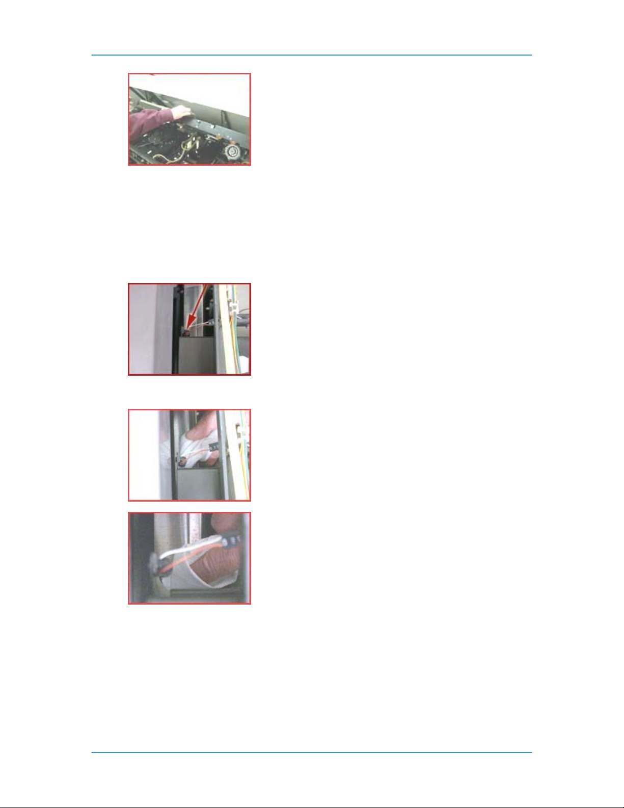
Solutions in Alphabetical Order
WARNING: You may have to hold the bypass transport in the raised position if it lowers into
the original position.
3. Stand directly in front of Finisher, just to the right of Paper Tray 3.
4. Look between the brown cover on your left, with the sticker of area 17, and the yellowish colored
tube to your right. You may need to lean over the Finisher area to find the sensor.
5. Look for a small orange and white wires. These wires lead to the Q1222 sensor.
6. Follow the wires down to the black, round sensor. This is the top of the sensor and the bottom of
the sensor is approximately 76 mm (3 inches) below it.
7. Wipe the top and bottom of the sensor gently with a soft cloth.
8. If present, lower the bypass transport. Close the Finisher Top Cover.
DT6180 HandyBook 76
Page 77

Solutions in Alphabetical Order
Clean the Front Stack (Q1227), Rear Stack Height (Q1218), and
Set Path (Q1221) Sensors
The Q1227, Q1218, Q1221 Sensors are on the Stacker Tray.
NOTE: Q1218 is a dual sensor containing Q1218 and Q1227.
1. Fold a Piece of A4 (216 mm x 279 mm / 8.3 x 11.7 inch) or 8.5 x 11 inch paper.
2. Open the Finisher Front Doors. The door is located above and to the right of Paper Tray 3.
3. Open the Finisher Top Cover.
4. If present, the bypass transport must be raised to gain access to the sensors.
WARNING: You may have to hold the bypass transport in the raised position if it lowers into
the original position.
Q1227 Front Stack Height Sensor:
DT6180 HandyBook 77
Page 78

Solutions in Alphabetical Order
5. On the upper right side of the opening, locate the label for area 19.
6. About 76 mm (3 inches) down from the label and all the way to the right of the opening you should
see three wires (red, orange and brown) leading to a black plastic block mounted on a met al
bracket. The plastic block, with small white letters on it, is the detector.
7. Clean the surface under the white letters with the folded piece of paper from Step 1.
8. On a horizontal line 254 mm (10 inches) left of the Q1227 detector, look under a 127 mm (5 inches)
long black metal bracket for a round bulb-like object about 10 mm (3/8 inches) in diameter. This is
the Q1227 Sensor and should be cleaned as well with a soft cloth.
Q1218 Rear Stack Height Sensor:
9. Stand in front of the stacker drawer. Along the right side of the area you exposed when you opened
the Finisher Top Cover, approximately 356 mm (14 inches) back from the front of the machine, look
for a yellow ground strap. The ground strap is bolted to the right hand side of the machine frame.
10. Carefully duck your head under the Finisher Top Cover so you can look into the Finisher, and the
area next to the ground strap.
CAUTION: If you are wearing a necklace you may want to tuck it in or remove it so it will not
DT6180 HandyBook 78
Page 79

Solutions in Alphabetical Order
get caught.
11. To the left of the ground strap attachment bolt, about 178 mm (7 inches) closer to the floor, you
should see a red, orange, and brown wire leading to a black plastic block mounted on a metal
bracket. The plastic block, with small white letters on it, is the detector.
12. About 254 mm (10 inches) left of the detector, under a long black metal bracket, is a round bulb-like
object. The object is about 10 mm (3/8 inch) in diameter, facing the surface you have just cleaned.
This is the Q1218 Sensor, and should be cleaned as well.
Q1221 Set Path Sensor:
13. Using the Q1218 sensor as a reference point, look about 38 mm (1 1/2 inch) closer to the front of
the machine. You should see the round sensor for Q1221 pointing straight up.
14. Put your finger on the Sensor and move your head to the left of the big black bracket so you can
see your finger on the Sensor again.
15. Clean the Sensor.
DT6180 HandyBook 79
Page 80

Solutions in Alphabetical Order
16. Look 76 mm (3 inches) directly above the sensor for orange and white wires. These wires are
attached to the detector which faces straight down.
17. Brush a folded sheet of paper across the Sensor.
18. Close the Finisher Front Doors. If present, lower the bypass transport. Close the Finisher Top
Cover.
Clean the Fuser (Q1010) and Prefuser Sensors (Q1009)
Clean both the Q1010 and Q1009 Sensor, beginning with the Q1010 Sensor.
WARNING: The surrounding area of the machine around the sensors can be extremely hot!
Cleaning the Q1010 Sensor:
1. Open the Processor Doors. The handle to open the doors is above Paper Tray 1.
2. Behind the left Processor Door, just to the left of Paper Tray 1, is a large green handle. Pull on the
handle and pull out the Fuser Module.
3. Locate the CAUTION label on top of the Fuser Module.
4. Approximately 25 mm (1 inch) to the left of the label is a small U-shaped cutout in the aluminum
frame and a tiny square mirror the size of your small fingernail.
DT6180 HandyBook 80
Page 81

Solutions in Alphabetical Order
5. Use a cotton swab to clean this mirror and the small plastic sensor to the right of the mirror. Make
sure you do not touch the hot surfaces in this area.
Cleaning the Q1009 Sensor:
6. To the left of Paper Tray 1, at the back of the Fuser Module, locate the area 7 label on the machine
frame.
7. Look inside the cutout area. You may need to kneel down so you can see inside the cutou t. To your
left is a clear plastic bottle containing Fuser Agent. Inside the cutout, and coming out on the side of
the plastic bottle, is a shiny metal tab. The right surface near the top of that tab is a mirror. About
10 mm (3/8 of an inch) to the right, facing the mirror, is the Q1009 sensor.
8. Clean the mirror and sensor with a small amount of Lens and Mirror Cleaner on a soft, lint-free
cloth.
9. Push the Fuser Module firmly back into the machine.
10. Close the Processor Doors.
DT6180 HandyBook 81
Page 82

Solutions in Alphabetical Order
Clean the Post Inverter (Q1202) and Output Transport (Q1203)
Sensors
NOTE: The Q1202 and Q1203 Sensors are in area 12.
1. Fold a sheet of 216 mm x 279 mm (8.5 x 11 inch) or A4 (21 0 mm x 29 7 mm / 8.3 x 11.7 inch) paper
twice to make a 51 mm (2 inch) wide strip. This will be used to clear the sensor.
2. Open the Finisher Doors. The handle for these doors is located above Paper Tray 3.
3. Open the Finisher Top Cover.
4. When you open the Finisher Top Cover you will see a mechanical assem bly on the left side of the
machine. The assembly has two sensors toward the front of the machine.
The sensors are shiny, black plastic rectangles, 6 mm (¼ inch) wide and 51 mm (2 inches) from
front to back and have a red, an orange, and a purple wire leading to them with small white
lettering. The Q1203 sensor is on the top front area of the assembly, and the Q1202 sensor is on
the left side of the assembly, about 254 mm (10 inches) from the top.
5. Pull on the green handle to open the access plate between the two sensors. Opening the access
plate allows easier access to both sensors.
DT6180 HandyBook 82
Page 83

Solutions in Alphabetical Order
To clean the Q1203 sensor:
6. Place the short edge of the folded paper above the white rollers on the left side of the Top Tray
Feeder, as near to the front of the machine as the feeder will let you. Push the paper edge under
the curved metal lip, past the near side of the black roller, and underneath the Q1202 Sensor.
7. Brush the folded piece of paper under the Q1203 Sensor a couple of times to clear any
obstructions.
To clean the Q1202 sensor:
8. Take the folded paper and place the short edged side into the area of the opened access plate. If
you hold the paper against the right side of that opening and slide the short edge toward you,
beneath the white rollers, you can work the paper under the sensor. Make sure that area is clear
from all obstructions.
9. Remove the paper, then close the access plate.
10. Lower the Finisher Top Cover until you hear it latch.
11. Close the Finisher Doors.
DT6180 HandyBook 83
Page 84

Solutions in Alphabetical Order
Clean the Pre-Fuser Sensor (Q1009)
CAUTION: The surrounding area of the machine around the sensor can be extremely hot!
To clean the Q1009 Sensor:
1. Open the right and left Processor Doors.
2. To the left of Paper Tray 1, at the back of the Fuser Module, locate the area 7 label on the machine
frame.
3. Below the label is a cutout area. Look inside the cutout area. You may need to kneel down so you
can see inside the cutout. To your left is a clear plastic bottle containing Fuser Agent. Inside the
cutout, and coming out on the side of the plastic bottle, is a shiny metal tab. The right surface near
the top of that tab is a mirror. About 10 mm (3/8 of an inch) to the right, facing the mirror, is the
Q1009 sensor. Also try following the purple and red wires, if you are having difficulties finding the
sensor.
4. Pull out the Fuser Module.
CAUTION: The Fuser may be hot!
5. Clean the mirror and sensor with a small amount of Lens and Mirror Cleaner on a soft, lint-free
cloth.
DT6180 HandyBook 84
Page 85

Solutions in Alphabetical Order
6. Clean the sensor with a small amount of Lens and Mirror Cleaner on a soft, lint-free cloth.
7. Push the Fuser Module firmly back into the machine.
8. Close the Processor Doors.
Clean the Registration Transport Sensor (Q861)
The Q861 Sensor is located in area 4, behind the area 4 green handle.
1. Open the Processor Door. The handle to open the door is above and to the left of Paper Tr ay 1.
2. Locate the area 4 green handle which is approximately 72 mm (2 inches) directly below the left side
of Tray 2.
3. Raise the green handle and the baffle that is attached, until it locks into place.
4. Locate the Q861 Sensor under the baffle. The sensor is in the front left corner and approximately
76 mm (3 inches) back from the handle.
CAUTION: To avoid damage to the machine, do not use any liquids or solvents of any kind
to clean the Q861 Sensor.
5. Gently rub a dry cleaning pad against the underside of the sensor, as illust rated, and move it left to
right to clean the sensor.
DT6180 HandyBook 85
Page 86

Solutions in Alphabetical Order
6. Lower the green handle by squeezing the front and rear plates of the handle together to release the
handle.
7. Close the Processor Door.
Clean the Set Path Sensor (Q1221)
NOTE: The Q1221 sensor is on the Stacker Tray. To locate the Q1221 sensor you need to locate the Q1218
sensor first.
To locate the Q1218 sensor:
1. Open the Finisher Doors. The handle for these doors is located above and to the right of Paper
Tray 3.
2. Open the Finisher Top Cover by pushing up on the handle in the top center of the cover.
DT6180 HandyBook 86
Page 87

Solutions in Alphabetical Order
3. If present, the bypass transport must be raised to gain access to the sensors.
WARNING: You may have to hold the bypass transport in the raised position if it lowers into
the original position.
4. Stand in front of the Stacker drawer. Along the right side of the area you exposed when you
opened the Finisher Top Cover, approximately 356 mm (14 inches) back from the front of the
machine, look for a yellow ground strap. The ground strap is bolted to the right hand side of the
machine frame.
5. Carefully duck your head under the Finisher Top Cover so you can look i nto the F inisher, and the
area next to the ground strap.
CAUTION: If you are wearing a necklace you may want to tuck it in or remove it so it will not
get caught.
6. To the left of the ground strap attachment bolt, about 178 mm (7 inches) closer to the floor, you
should see a red, orange, and brown wire leading to a black plastic block mounted on a metal
bracket. The plastic block with small white letters on it is the detector.
7. About 254 mm (10 inches) left of the detector, under a long black metal bracket, is a round bulb-like
object. The object is about 10 mm (3/8 inch) in diameter. This is the Q1218 sensor.
DT6180 HandyBook 87
Page 88

Solutions in Alphabetical Order
To locate the Q1221 Sensor:
8. Using the Q1218 sensor as a reference point, look about 38 mm (1 1/2 inch) closer to the front of
the machine. You should see the round sensor for Q1221 pointing straight up.
9. Put your finger on the sensor and move your head to the left of the big black bracket so you can
see your finger on the sensor again.
10. Clean the sensor.
11. Look 76 mm (3 inches) directly above the sensor for orange and white wires. These wires are
attached to the detector which faces straight down.
12. Using a soft, lint-free cloth, brush the cloth across the detector.
13. If present, lower the bypass transport. Close the Finisher Top Cover.
14. Close the Finisher Doors.
DT6180 HandyBook 88
Page 89

Solutions in Alphabetical Order
Clean the Tape Binder Area
Clean the Binder Tape area:
NOTE: It is highly recommended that the Binder be cleaned before the Binder warm-up cycle begins or
before powering ON the machine.
1. Open the Finisher Doors.
WARNING: All areas of the Binder drawer, including the Binder tape, are hot (approximately
425º F, 218º C) and may cause a serious burn. If the Binder has been in a "Ready" condition,
allow the Binder to cool for at least one hour before continuing the procedure.
2. Grasp the green handle on the Binder drawer. Pull the drawer out until it stops.
CAUTION: To avoid damage to the system, do not use any liquids or any abrasive material
to clean the Binder. Use the plastic Binder Platen Cleaner on the tape reel or use a clean,
lint-free cloth.
WARNING: A sharp edge on the plastic Binder Platen Cleaner or on the Tape Spool
sometimes occurs as a result of removing the cleaner. Thi s sharp edge could cut your
finger.
3. Locate and remove the plastic Binder Platen Cleaner from the Binder tape reel.
DT6180 HandyBook 89
Page 90

Solutions in Alphabetical Order
4. If Binder tape is in the area of the cleaner, pull the reel slightly away from the tape to avoid tape
damage.
5. Lift up on the cleaner and push down against the single end tab. Move the cleaner back and forth
until the end tab breaks.
6. Continue to move the cleaner in the same manner until the two-sided tab breaks.
Perform all of the following cleaning procedures in the order listed:
Cleaning the Tape Guides:
7. Use the Binder Platen Cleaner to clean the surfaces and grooves of the tape guides.
8. Make sure that all the glue is removed from the grooves on the tape guides.
Cleaning the Binder Platen:
9. Use the Binder Platen Cleaner to clean the top and side surfaces of the Binder platen until all the
glue is removed.
10. Make sure that the glue is removed from the grooves on the Binder platen surface, which align with
the top and bottom edges of the book.
Cleaning the Flappers:
11. Using the Binder Platen Cleaner, clean the top and side surfaces of the Binder flappers u ntil all th e
glue is removed.
DT6180 HandyBook 90
Page 91

Solutions in Alphabetical Order
Cleaning the Calipers:
12. Using the Binder Platen Cleaner, clean the Binder caliper surface until all the glue is removed.
Closing the Binder:
13. Push in the Binder drawer until it stops.
14. Close the Finisher Doors.
15. Place the platen cleaner in a safe place.
Clear Paper Jams in Areas 11, 12, 13, and 14
NOTE: Even if paper is not visible, go through the sequence to clear the paper jam. Carefully inspect the
rollers for any debris or torn pieces of paper. When clearing misfeeds, make sure a full sheet of paper is
cleared and there are no pieces of paper left in the machine.
To clear areas 11 and 14:
1. Open the left Finisher Door using the handle above Paper Tray 3.
2. Locate the green handle in the top left corner with an arrow pointing to the right. This is area 11.
DT6180 HandyBook 91
Page 92
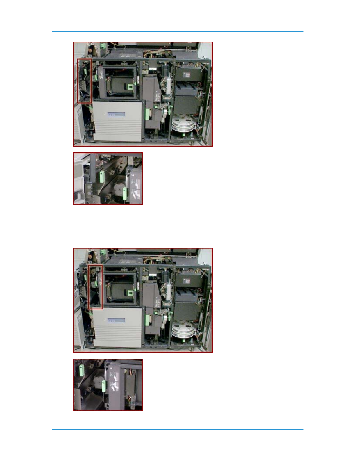
Solutions in Alphabetical Order
3. Grasp the handle and rotate it to the right.
4. Remove any paper in this area.
5. Rotate the handle to the left, to the latched position. If the handle does not stay in position when
released, it is not latched properly.
6. Locate the green handle in the top left corner with the arrow pointing to the left. This is Area 14.
DT6180 HandyBook 92
Page 93

Solutions in Alphabetical Order
7. Grasp the handle and rotate it to the left.
8. Remove any paper in this area.
9. Rotate the handle to the right, to the latched position. If the handle does not stay in position when
released, it is not latched properly.
10. Close the Finisher Door.
To clear areas 12 and 13:
1. Open the Finisher Top Cover by pushing up on the handle in the top center of the cover.
2. On the left side of the Finisher Top Cover there is a mechanical assembly. There is a green handle
on the left side of this assembly. This is area 12.
3. Grasp the green handle and rotate it to the left to open the baffle.
4. Remove any paper under the baffle.
5. Close the baffle.
6. Locate the green handle on the right side of the mechanical assembly. This is area 13.
DT6180 HandyBook 93
Page 94

Solutions in Alphabetical Order
7. Grasp the handle, push down on the top of the handle with your thumb, and then p ull the baffle
open toward the right.
8. Remove any paper under the baffle.
9. Close the baffle.
10. Close the Finisher Top Cover.
Clear Paper Jams in Areas 11, 12, and 13
NOTE: Even if paper is not visible, go through the sequence to clear the paper jam. Carefully inspect the
rollers for any debris or torn pieces of paper. When clearing misfeeds, make sure a full sheet of paper is
cleared and there are no pieces of paper left in the machine.
To clear area 11:
1. Open the left Finisher Door using the handle above Paper Tray 3.
2. Locate the green handle in the top left corner with an arrow pointing to the right. This is area 11.
DT6180 HandyBook 94
Page 95

Solutions in Alphabetical Order
3. Grasp the handle and rotate it to the right.
4. Remove any paper in this area.
5. Rotate the handle to the left, to the latched position. If the handle does not stay in position when
released, it is not latched properly.
6. Close the Finisher Door.
To clear areas 12 and 13:
7. Open the Finisher Top Cover by pushing up on the handle in the top center of the cover.
8. On the left side of the Finisher Top Cover there is a mechanical assembly. There is a green handle
on the left side of this assembly. This is area 12.
DT6180 HandyBook 95
Page 96

Solutions in Alphabetical Order
9. Grasp the green handle and rotate it to the left to open the baffle.
10. Remove any paper under the baffle.
11. Close the baffle.
12. Locate the green handle on the right side of the mechanica l assemb ly. This is area 13.
DT6180 HandyBook 96
Page 97

Solutions in Alphabetical Order
13. Grasp the handle, push down on the top of the handle with your thumb, and then pull the baffle
open toward the right.
14. Remove any paper under the baffle.
15. Close the baffle.
16. Close the Finisher Top Cover.
Clear Paper Jams in Areas 13, 14, and 15
NOTE: Even if paper is not visible, go through the sequence to clear the paper jam. Carefully inspect the
rollers for any debris or torn pieces of paper. When clearing misfeeds, make sure a full sheet of paper is
cleared and there are no pieces of paper left in the machine.
To clear area 13:
1. Open the Finisher Top Cover by lifting the handle to release the cover. Push the cover open all the
way.
2. If present, the bypass transport must be raised to gain access to the sensors.
WARNING: You may have to hold the bypass transport in the raised position if it lowers into
the original position.
3. On the left side of the Finisher area you will see a mechanical assembly. There is a green handle
on the right side of this assembly. Grasp the handle and push down on the top of the handle with
your thumb, then pull the baffle open toward the right.
DT6180 HandyBook 97
Page 98

Solutions in Alphabetical Order
4. Remove any paper under the baffle.
5. Close the baffle.
6. If present, lower the bypass transport. Close the Finisher Top Cover.
To clear area 14:
7. Open the left Finisher Door using the handle above Paper Tray 3.
8. Locate the green handle behind the door in the top left corner with an arrow pointing down to the
left. Grasp the handle and rotate it to the left.
DT6180 HandyBook 98
Page 99
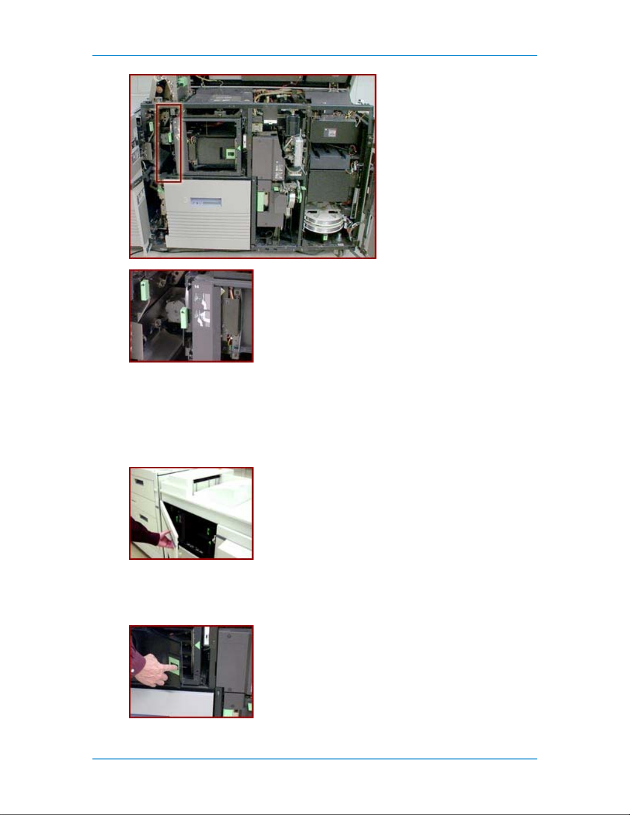
Solutions in Alphabetical Order
9. Remove any paper in this area.
10. Rotate the handle to the right until the handle latches into position. If the handle does not stay in
position when released, it is not latched properly.
To clear area 15:
11. Open the left Finisher Door using the handle above Paper Tray 3.
12. Open the Bindexer Door. The Bindexer Door, located above the Paper Tray 3 area, has a black
handle in the center of a large green sticker. Locate the green triangle pointing to a latch that is
surrounded by a light green rectangle. The door opens by grasping the handle as it is moved to the
left, and then pulling the handle out.
DT6180 HandyBook 99
Page 100

Solutions in Alphabetical Order
13. Remove any paper in the three bins behind the door.
14. Close the Bindexer Door.
15. Close the Finisher Door.
Clear Paper Jams in Areas 17 and 18
NOTE: Even if paper is not visible, go through the sequence to clear the paper jam. Carefully inspect the
rollers for any debris or torn pieces of paper. When clearing misfeeds, make sure a full sheet of paper is
cleared and there are no pieces of paper left in the machine.
To clear areas 17 and 18:
1. Open the Finisher Top Cover by lifting the handle to release the cover. Push the cover open all the
way.
2. Open the Finisher Doors.
3. Some machines will have a large silver colored transport under the top cover, approximately the
DT6180 HandyBook 100
 Loading...