

Page 1
Laser Multi-Function Center
SERVICE MANUAL
MODEL:
DCP-7030/7040/7045N
MFC-7320/7340/7440N/7450/
7840N/7840W
Read this manual thoroughly before carrying out any maintenance work.
Keep this manual in a convenient place for quick and easy reference at all times.
Jan 2008
SM-FAX088
8C5C
Confidential
Page 2

© Copyright Brother Industries, Ltd. 2008
Compilation and Publication:
This manual has been complied and published, under the supervision of Brother Industries Ltd.,
covering the latest product descriptions and specifications. The contents of this manual and the
specifications of this product are subject to change without notice. Brother reserves the right to make
changes without notice in the specifications and materials contained herein and shall not be
responsible for any damages (including consequential) caused by reliance on the materials presented,
including but not limited to typographical and other errors relating to the publication. This product is
designed for use in a professional environment.
Confidential
Page 3

PREFACE
This service manual contains basic information required for after-sales service of the Laser
Multi-Function Center (hereinafter referred to as "the machine"). This information is vital to
the service personnel to maintain the high printing quality and performance of the machine.
This service manual covers the DCP-7030/7040/7045N, MFC-7320/7340/7440N/7450/
7840N/7840W machines.
This manual consists of the following chapters:
CHAPTER 1: TROUBLESHOOTING
Details of error messages and codes that the incorporated self-diagnostic function of the
machine will display if any error or malfunction occurs. If any error message appears, refer to
this chapter to find which parts should be checked or replaced.
The latter half of this chapter provides sample problems that could occur in the main sections
of the machine and related troubleshooting procedures.
CHAPTER 2: PERIODICAL MAINTENANCE
Details of consumable parts and periodical maintenance parts. This chapter also covers
procedures for disassembling and assembling periodical maintenance parts.
CHAPTER 3: DISASSEMBLY AND ASSEMBLY
Details of procedures for disassembling and assembling of the machine together with related
notes. The disassembly order flow provided enables you to see at a glance the quickest way
to get to parts involved.
At the start of a disassembly job, you can check the disassembly order flow that guides you
through a shortcut to get to the object parts.
This chapter also covers screw tightening torques and lubrication points to which the
specified lubrications should be applied during assembly jobs.
CHAPTER 4: ADJUSTMENTS AND UPDATING OF SETTINGS, REQUIRED
AFTER PARTS REPLACEMENT
Details of adjustments and updating of settings, which are required if the main PCB and
some other parts have been replaced. This chapter also covers how to update the firmware.
CHAPTER 5: SERVICE FUNCTIONS
Describes the maintenance mode which is exclusively designed for the purpose of checking
the settings and adjustments using the keys on the panel.
This chapter also covers hidden function menus, which activate settings and functions or
reset the parts life.
CHAPTER 6: CIRCUIT DIAGRAMS, WIRING DIAGRAM
Provides the Circuit Diagrams and Wiring Diagram for the connections of the PCBs.
i
Confidential
Page 4

APPENDIX 1: WORKER SWITCH Settings (WSW)
APPENDIX 2: DELETION OF PERSONAL INFORMATION
APPENDIX 3: SERIAL NUMBERING SYSTEM
APPENDIX 4: SCREW CATALOGUE
APPENDIX 5: GLOSSARY
APPENDIX 6: REFERENCES
Information in this manual is subject to change due to improvement or redesign of the
product. All relevant information in such cases will be supplied in service information
bulletins (Technical Information).
A thorough understanding of this machine, based on information in this service manual and
service information bulletins, is required for maintaining its print quality performance and for
improving the practical ability to find the cause of problems.
There is the service reference manual as well. This service reference manual contains
“SPECIFICATIONS”, “THEORY OF OPERATION”, “TONER CARTRIDGE WEIGHT
INFORMATION”, “REFERENCES”, and “GLOSSARY”.
ii
Confidential
Page 5

TABLE OF CONTENTS
PREFACE ....................................................................................................................i
REGULATION .........................................................................................................viii
SAFETY INFORMATION ..........................................................................................xii
CHAPTER 1 TROUBLESHOOTING ................................................................... 1-1
1. INTRODUCTION ......................................................................................................................... 1-1
1.1 Precautions ......................................................................................................................... 1-1
1.2 Part names ......................................................................................................................... 1-2
1.3 Initial Check ........................................................................................................................ 1-4
2. ERROR CAUSE .......................................................................................................................... 1-6
2.1 Error indication .................................................................................................................... 1-6
2.2 Error Code Cause and Remedy ......................................................................................... 1-7
2.2.1 Recoverable User Check Errors ............................................................................ 1-7
2.2.2 Service Call Error ................................................................................................... 1-7
3. PAPER FEEDING PROBLEMS ................................................................................................. 1-23
3.1 No Feeding ....................................................................................................................... 1-23
3.2 Double Feeding ................................................................................................................ 1-23
3.3 Paper Jam ........................................................................................................................ 1-24
3.4 Dirt on Paper ..................................................................................................................... 1-25
3.5 Wrinkles or creases .......................................................................................................... 1-25
3.6 Waves in the paper / folds in the paper at the eject roller 2 .............................................. 1-25
3.7 Curl in the paper ............................................................................................................... 1-26
4. TROUBLESHOOTING OF DOCUMENT FEEDING .................................................................. 1-27
4.1 No Feeding ....................................................................................................................... 1-27
4.2 Double feeding ................................................................................................................. 1-27
4.3 Paper Jam ........................................................................................................................ 1-28
5. IMAGE DEFECT TROUBLESHOOTING (Defect Of the Print) .................................................. 1-29
5.1 Image Defect Examples .................................................................................................... 1-29
5.2 Diameter of Rollers ........................................................................................................... 1-29
5.3 Troubleshooting Image Defect .......................................................................................... 1-30
6. TROUBLESHOOTING OF SCANNIG ....................................................................................... 1-43
6.1 Cannot scan the document in the FB unit.
(If scan the document, it is completely white or black.) .................................................... 1-43
6.2 Cannot scan the document in the ADF unit.
(If scan the document, it is completely white or black.) .................................................... 1-43
6.3 Print of the scanning document is light or dark ................................................................. 1-44
6.4 Vertical streaks (White or Black vertical streaks) .............................................................. 1-44
iii
Confidential
Page 6

6.5 Poor fixing ......................................................................................................................... 1-44
6.6 Image distortion ................................................................................................................ 1-44
7. SOFTWARE SETTING PROBLEMS ......................................................................................... 1-45
8. NETWORK PROBLEMS ........................................................................................................... 1-46
9. TROUBLESHOOTING OF THE COMMUNICATIONS ERROR ................................................ 1-47
10. Troubleshooting of the control panel ......................................................................................... 1-51
11. Troubleshooting of fax functions ................................................................................................ 1-53
12. OTHERS PROBLEMS ............................................................................................................... 1-57
CHAPTER 2 PERIODICAL MAINTENANCE ...................................................... 2-1
1. CONSUMABLE PARTS ............................................................................................................... 2-1
2. PERIODICAL PEPLACEMENT PARTS ...................................................................................... 2-2
CHAPTER 3 DISASSEMBLY AND ASSEMBLY ................................................ 3-1
1. SAFETY PRECAUTIONS ............................................................................................................ 3-1
2. PACKING ..................................................................................................................................... 3-2
3. SCREW TORQUE LIST .............................................................................................................. 3-3
4. LUBRICATION ............................................................................................................................. 3-5
5. OVERVIEW OF GEARS .............................................................................................................. 3-8
6. HARNESS ROUTING .................................................................................................................. 3-9
7. DISASSEMBLY FLOW .............................................................................................................. 3-15
8. DISASSEMBLY PROCEDURE .................................................................................................. 3-16
8.1 SEPARATION PAD ASSY ................................................................................................ 3-17
8.2 FRONT COVER ASSY ..................................................................................................... 3-18
8.2.1 FRONT COVER ASSY ......................................................................................... 3-18
8.2.2 PAPER STOPPER L / PAPER STOPPER S ....................................................... 3-20
8.3 BACK COVER / OUTER CHUTE ASSY ........................................................................... 3-21
8.3.1 BACK COVER ...................................................................................................... 3-21
8.3.2 OUTER CHUTE ASSY ......................................................................................... 3-22
8.4 FUSER COVER ASSY ..................................................................................................... 3-23
8.4.1 FUSER COVER ASSY ......................................................................................... 3-23
8.4.2 EJECT ACTUATOR / EJECT ACTUATOR SPRING ........................................... 3-24
8.4.3 EJECT ROLLER ASSY 1 / BUSH C / BUSH R / BUSH L ................................... 3-25
8.5 JOINT COVER SUB CHUTE ASSY ................................................................................. 3-26
8.6 INNER CHUTE ASSY ....................................................................................................... 3-27
8.7 FUSER UNIT .................................................................................................................... 3-28
8.8 CORNER COVER ............................................................................................................ 3-30
iv
Confidential
Page 7

8.9 SIDE COVER L ASSY / SIDE COVER SUB L ................................................................. 3-31
8.9.1 SIDE COVER L ASSY .......................................................................................... 3-31
8.9.2 SIDE COVER SUB L ............................................................................................ 3-32
8.10 MAIN SHIELD COVER PLATE ......................................................................................... 3-32
8.11 ADF UNIT ......................................................................................................................... 3-33
8.11.1 ADF UNIT ............................................................................................................. 3-33
8.11.2 HINGE R / HINGE ARM / HINGE ASSY L ........................................................... 3-35
8.11.3 ADF COVER ASSY .............................................................................................. 3-36
8.11.4 GEAR COVER ..................................................................................................... 3-36
8.11.5 DOCUMENT SEPARATOR ROLLER SHAFT ASSY ........................................... 3-37
8.11.6 UPPER DOCUMENT CHUTE ASSY ................................................................... 3-38
8.11.7 LOWER DOCUMENT CHUTE ASSY .................................................................. 3-40
8.11.8 ADF SENSOR PCB ASSY ................................................................................... 3-41
8.11.9 LF ROLLER ASSY ............................................................................................... 3-43
8.11.10EJECTION ROLLER ASSY .................................................................................. 3-44
8.11.11DRIVE FRAME ASSY .......................................................................................... 3-45
8.11.12ADF MOTOR ........................................................................................................ 3-46
8.11.13PRESSURE ROLLER ASSY ................................................................................ 3-47
8.11.14DOCUMENT STOPPER ...................................................................................... 3-48
8.11.15DOCUMENT DRESS COVER ............................................................................. 3-49
8.12 DOCUMENT SCANNER UNIT ......................................................................................... 3-50
8.12.1 DOCUMENT SCANNER UNIT ............................................................................. 3-50
8.12.2 CORD HOOK ....................................................................................................... 3-52
8.12.3 PANEL UNIT ........................................................................................................ 3-52
8.12.4 PANEL PCB ASSY ............................................................................................... 3-53
8.12.5 RUBBER KEYS L/R ............................................................................................. 3-53
8.12.6 LCD ...................................................................................................................... 3-54
8.12.7 PRINTED PANEL COVER ................................................................................... 3-54
8.12.8 ADDRESS LABEL ................................................................................................ 3-55
8.13 PULL ARM L/R ................................................................................................................. 3-56
8.14 PULL ARM GUIDE ........................................................................................................... 3-57
8.15 NCU PCB .......................................................................................................................... 3-58
8.16 SPEAKER UNIT ............................................................................................................... 3-59
8.17 BATTERY ASSY ............................................................................................................... 3-61
8.18 SIDE COVER R ASSY ..................................................................................................... 3-62
8.19 REGISTRATION GROUNDING SPRING ......................................................................... 3-63
8.20 ROLLER HOLDER ASSY ................................................................................................. 3-64
8.21 WIRELESS LAN PCB ASSY (only MFC7840W) .............................................................. 3-66
8.22 MAIN PCB ASSY .............................................................................................................. 3-67
8.23 JOINT COVER ASSY / PAPER SUPPORTER ................................................................ 3-68
8.24 HIGH-VOLTAGE PS PCB ASSY ...................................................................................... 3-70
8.25 NEW TONER SENSOR HARNESS ASSY ....................................................................... 3-71
8.26 FILTER ASSY ................................................................................................................... 3-72
8.27 LASER UNIT ..................................................................................................................... 3-73
v
Confidential
Page 8

8.28
FAN MOTOR 60 UNIT / COVER SENSOR HARNESS ASSY / TONER LED PCB ASSY
8.28.1 FAN MOTOR 60 UNIT ......................................................................................... 3-75
8.28.2 COVER SENSOR HARNESS ASSY ................................................................... 3-76
8.28.3 TONER LED PCB ASSY ...................................................................................... 3-77
8.29 LVPS ................................................................................................................................ 3-78
8.29.1 LVPS PCB UNIT .................................................................................................. 3-78
8.29.2 LV SHIELD PLATE 2 ............................................................................................ 3-80
8.30 REGISTRATION FRONT SENSOR PCB ASSY .............................................................. 3-81
8.31 REGISTRATION REAR SENSOR PCB ASSY ................................................................. 3-85
8.32 DRIVE SUB ASSY ............................................................................................................ 3-88
8.33
DEV JOINT / DEV GEAR JOINT/53R / REGISTRATION PENDULUM GEAR SPRING
8.34 THERMISTOR HARNESS UNIT ...................................................................................... 3-91
8.35 TONER SENSOR PCB UNIT ASSY ................................................................................. 3-92
8.36 REGISTRATION SOLENOID / T1 SOLENOID ................................................................ 3-93
8.36.1 REGISTRATION SOLENOID ............................................................................... 3-93
8.36.2 T1 SOLENOID ...................................................................................................... 3-95
8.37 MAIN SHIELD PLATE / EJECT SENSOR PCB ASSY ..................................................... 3-96
8.38 RUBBER FOOT .............................................................................................................. 3-100
........ 3-75
........ 3-90
8.39 MAIN FRAME L ASSY .................................................................................................... 3-101
CHAPTER 4 ADJUSTMENTS AND UPDATING OF SETTINGS,
REQUIRED AFTER PARTS REPLACEMENT .............................. 4-1
1. IF YOU REPLACE THE MAIN PCB ............................................................................................. 4-1
2. IF YOU REPLACE THE WIRELESS LAN PCB ......................................................................... 4-10
3. IF YOU REPLACE THE LASER UNIT ....................................................................................... 4-11
4. IF YOU REPLACE THE FB UNIT .............................................................................................. 4-12
CHAPTER 5 SERVICE FUNCTIONS .................................................................. 5-1
1. MAINTENANCE MODE ............................................................................................................... 5-1
1.1 How to Enter the Maintenance Mode ................................................................................. 5-1
1.2 How to Enter the End User-accessible Maintenance Mode ............................................... 5-1
1.3 List of Maintenance-mode Functions .................................................................................. 5-2
1.4 Detailed Description of Maintenance-mode Functions ....................................................... 5-3
1.4.1 EEPROM Parameter Initialization (Function code 01, 91) ..................................... 5-3
1.4.2 Printout of Scanning Compensation Data (Function code 05) ............................... 5-4
1.4.3 Placement of CIS Unit in Position for Transportation (Function code 06) .............. 5-6
1.4.4 ADF Performance Test (Function code 08) ............................................................ 5-6
1.4.5 Test Pattern (Function code 09) ............................................................................. 5-7
1.4.6 Worker Sw WSW) Setting and Printout ................................................................. 5-8
1.4.7 Operational Check of LCD (Function code 12) .................................................... 5-13
1.4.8 Operational Check of Control Panel Button (Function code 13) .......................... 5-14
1.4.9 ROM Version Check (Function code 25) .............................................................. 5-15
vi
Confidential
Page 9

1.4.10 Operational Check of Sensors (Function code 32) .............................................. 5-16
1.4.11 PC Print Function setting (Function code 32) ....................................................... 5-18
1.4.12 Received Data Transfer Function (Function code 53)
(MFC-7840W/7840N/7450/7440N/7340/7320 only) ............................................. 5-22
1.4.13 Fine Adjustment of Scan Start/End Positions (Function code 54) ........................ 5-24
1.4.14 Acquisition of White Level Data (Function code 55) ............................................. 5-26
1.4.15 Paper Feeding and Ejecting Test (Function code 67) .......................................... 5-26
1.4.16 EEPROM Customizing (Function code 74) .......................................................... 5-27
1.4.17 Operational Check of Fans (Function code 78) .................................................... 5-29
1.4.18 Display of the Machine's Log Information (Function code 80) .............................. 5-31
1.4.19 Error Code Indication (Function code 82) ............................................................ 5-33
1.4.20 Output of Transmission Log to the Telephone Line (Function code 87)
(only MFC7840W/7840N/7450/7440N/7340/7320) .............................................. 5-33
1.4.21 Exit from the Maintenance Mode (Function code 99) ........................................... 5-34
2. OTHER SERVICE FUNCTIONS ................................................................................................ 5-35
2.1 User Maintenance Mode ................................................................................................... 5-35
2.2 Resetting the developing bias voltage counter ................................................................. 5-36
CHAPTER 6 CIRCUIT DIAGRAMS, WIRING DIAGRAM ................................... 6-1
APPENDIX 1 WORKER SWITCH Settings (WSW) ................................... App. 1-1
APPENDIX 2 DELETION OF PERSONAL INFORMATION ....................... App. 2-1
APPENDIX 3 SERIAL NUMBERING SYSTEM .......................................... App. 3-1
APPENDIX 4 SCREW CATALOGUE ......................................................... App. 4-1
APPENDIX 5 GLOSSARY .......................................................................... App. 5-1
APPENDIX 6 REFERENCES ...................................................................... App. 6-1
vii
Confidential
Page 10

REGULATION
<For Europe and Other countries>
■ Radio interference (220 to 240 volt model only)
This machine follows EN55022 (CISPR Publication 22)/Class B.
■ IEC 60825-1 specification (220 to 240 volt model only)
This machine is a Class 1 laser product as defined in IEC 60825-1 specifications. The label
shown below is attached in countries where it is needed.
CLASS 1 LASER PRODUCT
APPAREIL À LASER DE CLASSE 1
LASER KLASSE 1 PRODUKT
This machine has a Class 3B laser diode which produces invisible laser radiation in the laser
unit. You should not open the laser unit under any circumstances.
Caution
Use of controls or adjustments or performance of procedures other than those specified in
this manual may result in hazardous radiation exposure.
For Finland and Sweden
LUOKAN 1 LASERLAITE
KLASS 1 LASER APPARAT
Varoitus!
Laitteen käyttäminen muulla kuin tässä käyttöohjeessa mainitulla tavalla saattaa altistaa
käyttäjän turvallisuusluokan 1 ylittävälle näkymättömälle lasersäteilylle.
Varning
Om apparaten används på annat sätt än i denna Bruksanvisning specificerats, kan
användaren utsättas för osynlig laserstrålning, som överskrider gränsen för laserklass 1.
viii
Confidential
Page 11

■ Internal laser radiation
Maximum radiation power: 10 mW
Wave length: 780 - 800 nm
Laser class: Class 3B
■ EU Directive 2002/96/EC and EN50419
(European Union only)
This equipment is marked with the recycling symbol below. It means that at the end of the life
of the equipment you must dispose of it separately at an appropriate collection point and not
place it in the normal domestic unsorted waste stream. This will benefit the environment for
all. (European Union only)
ix
Confidential
Page 12

<For USA and Canada>
■ Federal Communications Commission (FCC) Declaration of Conformity
(For USA)
Responsible Party: Brother International Corporation
100 Somerset Corporate Boulevard
P.O. Box 6911
Bridgewater, NJ 08807-0911
USA
Telephone: (908) 704-1700
declares, that the products
Product name: Laser Multi Function Center DCP-7030/7040/7045N,
MFC-7320/7340/7440N/7450/7840N/7840W
complies with Part 15 of the FCC Rules. Operation is subject to the following two conditions:
(1) This device may not cause harmful interference, and (2) this device must accept any
interference received, including interference that may cause undesired operation.
This equipment has been tested and found to comply with the limits for a Class B digital
device, pursuant to Part 15 of the FCC Rules. These limits are designed to provide
reasonable protection against harmful interference in a residential installation. This
equipment generates, uses, and can radiate radio frequency energy and, if not installed and
used in accordance with the instructions, may cause harmful interference to radio
communications. However, there is no guarantee that interference will not occur in a
particular installation. If this equipment does cause harmful interference to radio or television
reception, which can be determined by turning the equipment off and on, the end user is
encouraged to try to correct the interference by one or more of the following measures:
• Reorient or relocate the receiving antenna.
• Increase the separation between the equipment and receiver.
• Connect the equipment into an outlet on a circuit different from that to which the receiver is
connected.
• Consult the dealer or an experienced radio/TV technician for help.
Important
A shielded interface cable should be used to ensure compliance with the limits for a Class B
digital device. Changes or modifications not expressly approved by Brother Industries, Ltd.
could void the user’s authority to operate the equipment.
x
Confidential
Page 13

■ Industry Canada Compliance Statement (For Canada)
This Class B digital apparatus complies with Canadian ICES-003.
Cet appareil numérique de la classe B est conforme à la norme NMB-003 du Canada.
■ Laser Safety (110 to 120 volt model only)
This machine is certified as a Class 1 laser product under the U.S. Department of Health
and Human Services (DHHS) Radiation Performance Standard according to the Radiation
Control for Health and Safety Act of 1968. This means that the machine does not produce
hazardous laser radiation.
Since radiation emitted inside the machine is completely confined within protective housings
and external covers, the laser beam cannot escape from the machine during any phase of
user operation.
■ FDA Regulations (110 to 120 volt model only)
The U.S. Food and Drug Administration (FDA) has implemented regulations for laser
products manufactured on and after August 2, 1976. Compliance is mandatory for products
marketed in the United States. The following label on the back of the machine indicates
compliance with the FDA regulations and must be attached to laser products marketed in the
United States.
MANUFACTURED:
Brother Technology (Shenzhen) Ltd.
NO6 Gold Garden Ind., Nanling Buji, Longgang, Shenzhen, China
This product complies with FDA performance standards for laser products except for
deviations pursuant to Laser Notice No.50, dated Jun 24, 2007.
■ Internal laser radiation
Maximum radiation power: 10 mW
Wave length: 780 - 800 nm
Laser class: Class 3B
xi
Confidential
Page 14
SAFETY INFORMATION
■ Caution for Laser Product (WARNHINWEIS fur Laser drucker)
CAUTION: When servicing the machine and it is operated with the cover open, the
regulations of VBG 93 and the performance instructions for VBG 93 are
valid.
CAUTION: In case of any trouble with the laser unit, replace the laser unit itself. To
prevent direct exposure to the laser beam, do not try to open the enclosure
of the laser unit.
ACHTUNG: Im Falle von Störungen der Lasereinheit muß diese ersetzt werden. Das
Gehäuse der Lasereinheit darf nicht geöffnet werden, da sonst
Laserstrahlen austreten können.
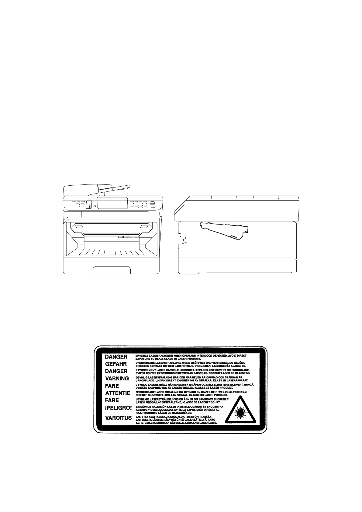
<Location of the laser beam window>
■ Additional Information
When servicing the optical system of the machine, be careful not to place a screwdriver or
other reflective object in the path of the laser beam. Be sure to take off any personal
accessories such as watches and rings before working on the machine. A reflected beam,
though invisible, can permanently damage the eyes.
Since the beam is invisible, the following caution label is attached on the laser unit.
xii
Confidential
Page 15

■ Definitions of Warnings, Cautions, Notes and Memos
The following conventions are used in this manual:
Mark Contents
Warnings tell you what to do to prevent possible personal injury.
Electrical Hazard icons alert you to a possible electrical shock.
Hot Surface icons warn you not to touch machine parts that are hot.
Cautions specify procedures you must follow or avoid to prevent
possible damage to the machine or other objects.
Note Notes tell you useful tips when servicing the machine.
Memo Memo tells you bits of knowledge to help understand the machine.
xiii
Confidential
Page 16
■ Safety Precautions
Please keep these instructions for later reference and read them before attempting any
maintenance.
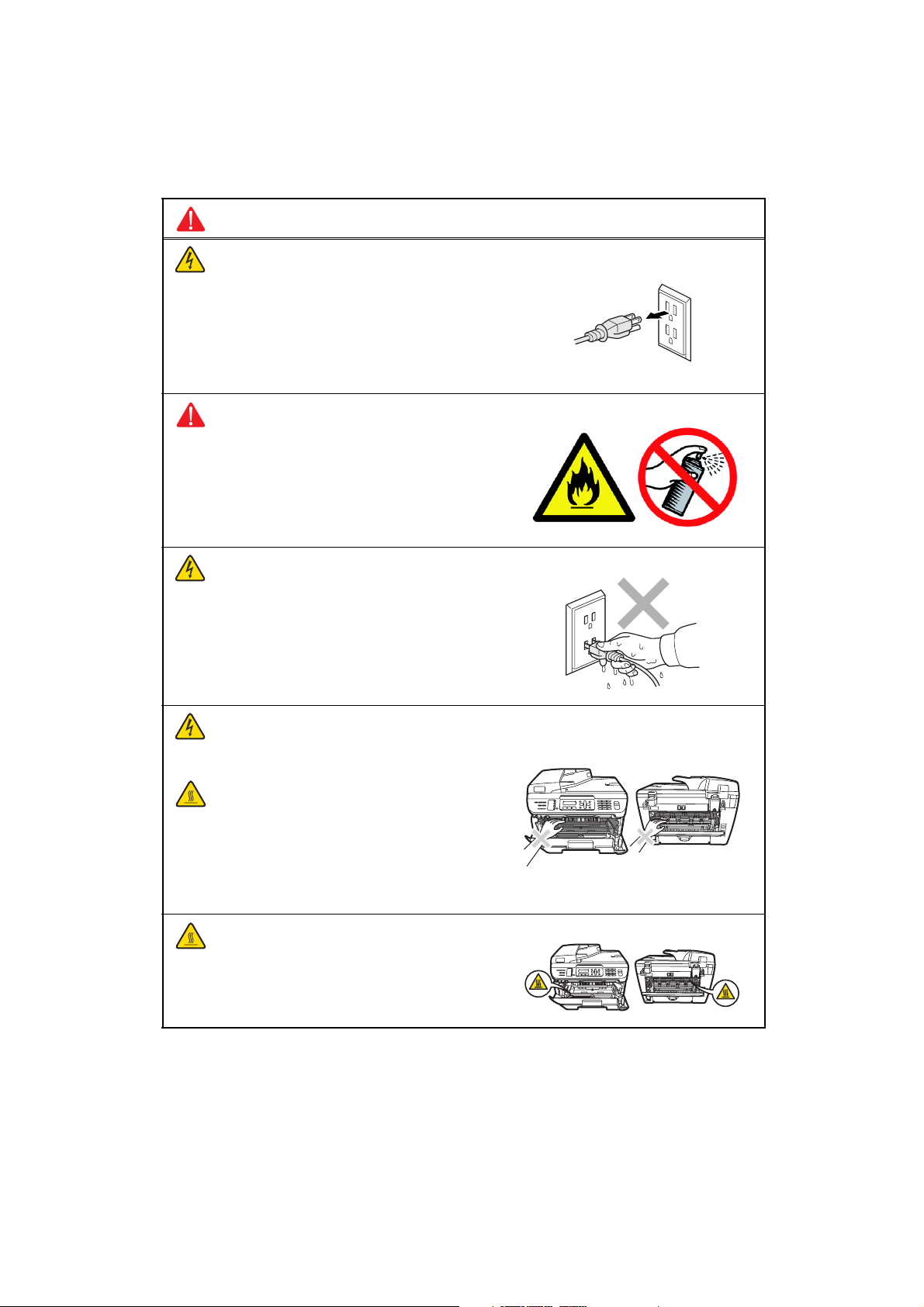
WARNING
There are high voltage electrodes inside the
machine. Before you clean the inside of the
machine, make sure you have unplugged the
telephone line cord first and then the power
cord from the AC power outlet (See Routine
maintenance on page 115.)
DO NOT use flammable substances or any
type of spray to clean the inside or outside of
the machine. Doing this may cause a fire or
electrical shock. Refer to Routine maintenance
on page 115 for how to clean the machine.
DO NOT handle the plug with wet hands.
Doing this might cause an electrical shock.
Always make sure the plug is fully inserted.
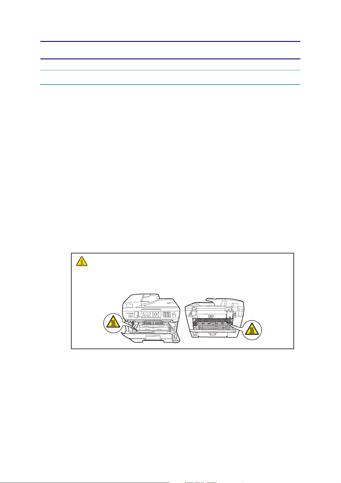
After you have just used the machine, some
internal parts of the machine will be extremely
hot. When you open the front or back cover of
the machine, DO NOT touch the shaded parts
shown in the illustration.
The fuser unit is marked with a caution label.
Please DO NOT remove or damage the label.
xiv
Confidential
Page 17
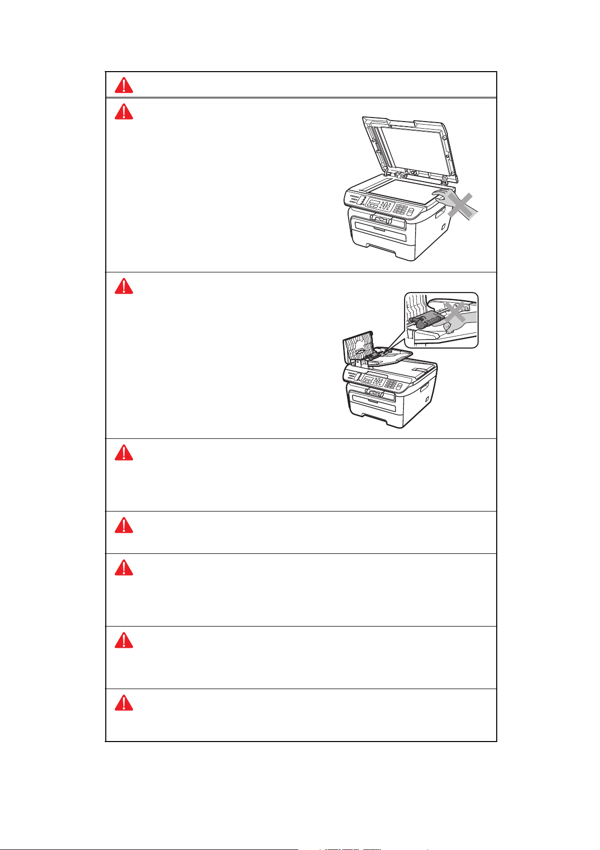
WARNING
To prevent injuries, be careful not to put your
hands on the edge of the machine under the
document cover or scanner cover.
To prevent injuries, be careful not to put your
fingers in the area shown in the illustration.
DO NOT use a vacuum cleaner to clean up scattered toner. Doing this might cause
the toner dust to ignite inside the vacuum cleaner, potentially starting a fire. Please
carefully clean the toner dust with a dry, lint-free cloth and dispose of it according to
local regulations.
When you move the machine, grasp the side hand holds that are under the scanner.
Use caution when installing or modifying telephone lines. Never touch telephone
wires or terminals that are not insulated unless the telephone line has been
unplugged at the wall jack. Never install telephone wiring during a lightning storm.
Never install a telephone wall jack in a wet location.
This product must be installed near an AC power outlet that is easily accessible. In
case of an emergency, you must disconnect the power cord from the AC power outlet
to shut off the power completely.
To reduce the risk of shock or fire, use only a No. 26 AWG or larger
telecommunication line cord.
xv
Confidential
Page 18

CAUTION
Lightning and power surges can damage this product! We recommend that you use a
quality surge protection device on the AC power line and on the telephone line, or
unplug the cords during a lightning storm.
WARNING
IMPORTANT SAFETY INSTRUCTIONS
When using your telephone equipment, basic safety precautions should always be
followed to reduce the risk of fire, electric shock and injury to people, including the
following:
1 DO NOT use this product near water, for example, near a bath tub, wash bowl,
kitchen sink, washing machine, or in a wet basement or near a swimming pool.
2 Avoid using this product during an electrical storm. There may be a remote risk of
electric shock from lightning.
3 DO NOT use this product to report a gas leak in the vicinity of the leak.
4 Use only the power cord provided with the machine.
5 DO NOT dispose of batteries in a fire. They may explode. Check with local codes
for possible special disposal instructions.
SAVE THESE INSTRUCTIONS
xvi
Confidential
Page 19
CHAPTER 1 TROUBLESHOOTING
1. INTRODUCTION
Troubleshooting is the countermeasure procedures that the service personnel should follow if
an error or malfunction occurs with the machine. It is impossible to anticipate all of the
possible problems which may occur in future and determine the troubleshooting procedures,
so this chapter covers some sample problems. However, these samples will help the service
personnel pinpoint and repair other defective elements.
1.1 Precautions
Be sure to observe and follow all the precautions to prevent any secondary problems from
happening during troubleshooting.
(1) Always turn off the power and unplug the power cable before removing any covers or
PCBs, adjusting the machine and so on. If you need to take voltage measurements with
the power switched on, take the greatest of care not to receive an electric shock.
(2) When connecting or disconnecting cable connectors, make sure that you hold the
connector body and not the cables.
(3) Electronic devices are sensitive to static build up; make sure that you touch a metal
portion of the machine to discharge yourself before accessing the PCBs.
Handle PCBs with care when repairing them.
(4) Ensure all Warnings are followed.
The fuser unit becomes extremely hot during operation. Wait until it has cooled down
sufficiently before replacing consumable items. DO NOT remove or damage the
caution label located on or around the fuser.
(5) Verify again that the repaired portion works properly.
1-1
Confidential
Page 20
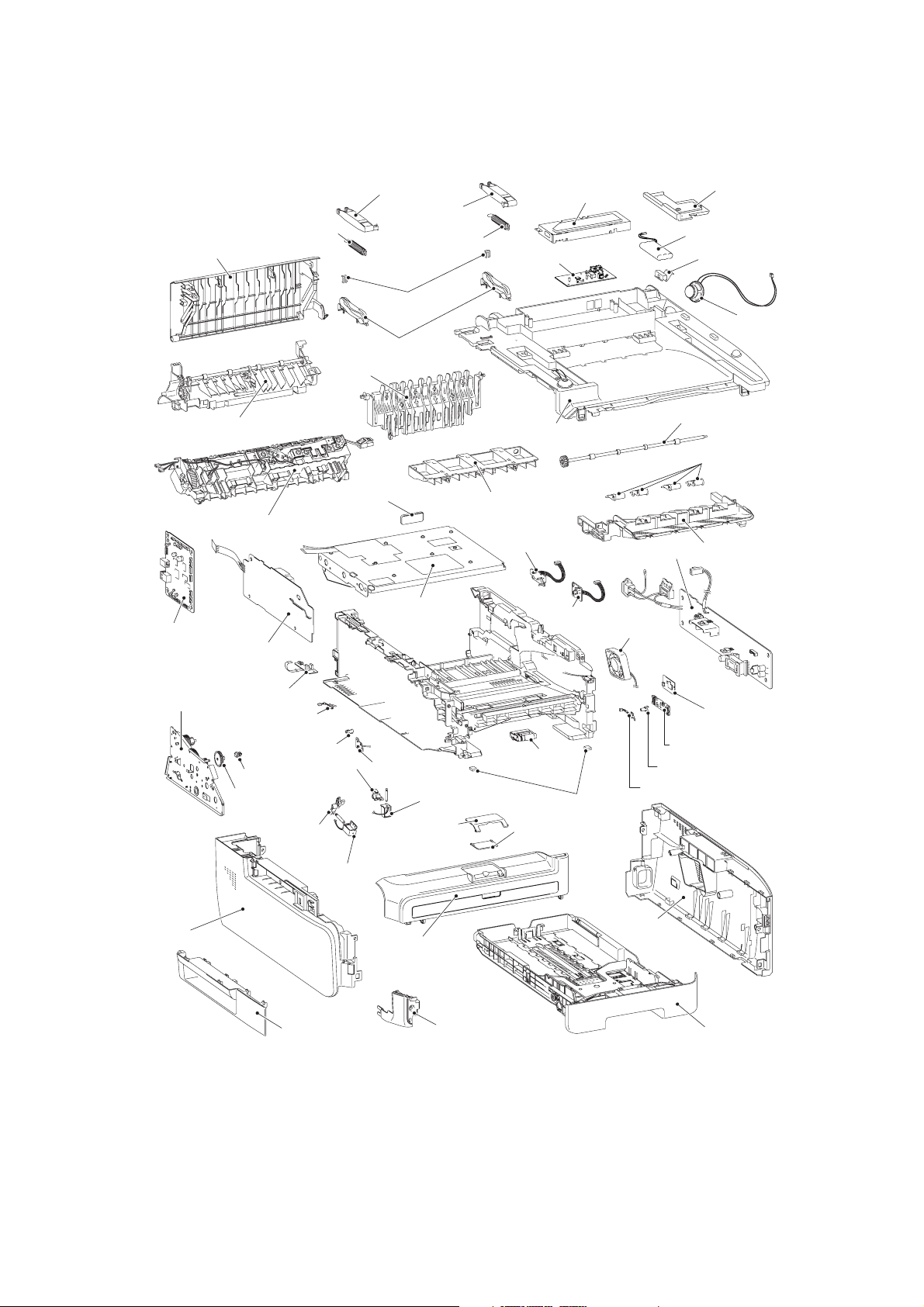
1.2 Part names
■ Printer part
Back cover
Main PCB ASSY
Pull arm spring ADF R
Fuser cover
Fuser unit
High-voltage
PS PCB ASSY
Pull arm R
Lock claw
Pull arm guide
Outer chute ASSY
Filter ASSY
Pull arm L
Pull arm spring ADF
Joint cover sub chute ASSY
Laser unit
NCU PCB
Joint cover ASSY
Registration rear
sensor PCB ASSY
NCU shield
PS PCB unit ASSY
Registration front
sensor PCB ASSY
Fan motor
60 unit
Speaker cover
Battery ASSY
Speaker hold spring
Speaker unit
Eject roller ASSY 2
Paper stack lever
Inner chute ASSY
Eject sensor PCB ASSY
Drive sub ASSY
Side cover L ASSY
New toner sensor
harness ASSY
PT sensor holder
DEV joint
DEV gear
joint/53R
Registration
solenoid lever
Registration
Side cover sub L
T1 solenoid
lever
solenoid
Toner sensor PCB
unit ASSY
T1 solenoid
Paper
stopper L
Front cover ASSY
Fig. Ref. 1-1
Corner cover
Roller holder
ASSY
Rubber foot
Paper
stopper S
Toner LED PCB ASSY
LED holder
Cover sensor harness ASSY
Side cover
R ASSY
Wireless LAN
PCB ASSY
Paper tray ASSY
1-2
Confidential
Page 21
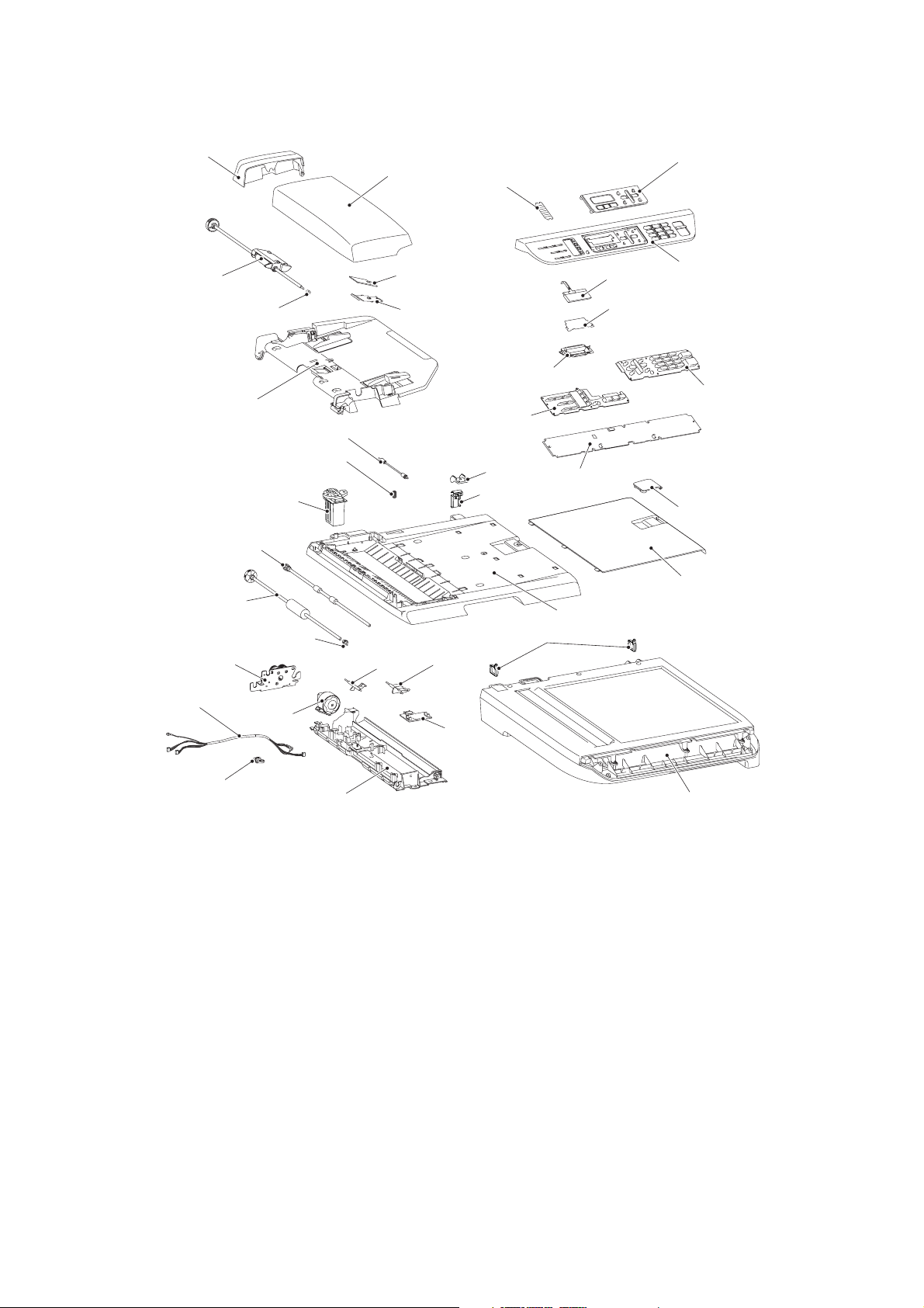
■ ADF / FB part
Gear cover
Separate roller shaft ASSY
Separate roller bushing
Upper document chute ASSY
Pressure roller ASSY
Pressure roller spring
Hinge ASSY L
Ejection roller ASSY
LF roller ASSY
LF roller bushing
Drive frame ASSY
ADF cover
Actuator L
Separation rubber
ADF plate spring
Actuator R
Address label
Back light guide
Rubber key L
Hinge R
Hinge arm
Document cover sub ASSY
Cord hook
Panel dress cover
Panel unit
LCD
Diffusion film
Rubber key R
Panel PCB ASSY
Document stopper
Document dress cover
ADF harness unit
harness holder
ADF motor
Lower document chute ASSY
ADF sensor
PCB ASSY
Fig. Ref. 1-2
Document scanner unit
1-3
Confidential
Page 22

1.3 Initial Check
Check the following items before attempting to repair the machine.
■ Operating Environment
(1) Put your machine on a flat, stable surface such as a desk that is free of vibration and
shocks.
(2) Use the machine in a well-ventilated room; use the machine within the following ranges
of temperature and humidity: temperature between 10°C and 32.5°C (50°F to 90.5°F),
and the relative humidity is maintained between 20% and 80%.
(3) The machine is not exposed to direct sunlight, excessive heat, moisture, or dust.
■ Power Supply
(1) The AC input power supply described on the rating plate of the machine should be within
±10% of the rated voltage.
(2) The AC input power supply is within the regulated value.
(3) The cables and harnesses are connected correctly.
(4) The fuses are not blown.
■ Paper
(1) A recommended type of paper is being used.
(Refer to “2.6 Paper”, Reference 1 of the Service Reference Manual.)
(2) The paper is not damp.
(3) The paper is not short-grained paper or acid paper.
■ Consumable Parts
(1) The drum unit (including the toner cartridge) is installed correctly.
■ Others
(1) Condensation
When the machine is moved from a cold place into a warm room, condensation may
occur inside the machine, causing various problems as listed below.
• Condensation on the optical surfaces such as the scanner window, lenses, the
reflection mirror and the protection glass may cause the print image to be light.
• If the exposure drum is cold, the electrical resistance of the photosensitive layer is
increased, making it impossible to obtain the correct contrast when printing.
• Condensation on the charge unit may cause corona charge leakage.
• Condensation on the plate and separation pad may cause paper feed failures.
If condensation has occurred, leave the machine for at least 2 hours to allow it to reach
room temperature.
If the drum unit is unpacked soon after it is moved from a cold place to a warm room,
condensation may occur inside the unit which may cause incorrect images. Instruct the
end user to allow the unit to come to room temperature before unpacking it. This will take
one or two hours.
1-4
Confidential
Page 23

(2) Cleaning
Use a soft dry cloth.
CAUTION:
DO NOT use flammable substances or any type of spray to clean the inside or outside
of the machine. Doing this may cause a fire or electrical shock.
1-5
Confidential
Page 24
2. ERROR CAUSE
This machine includes a self-diagnosis function. If the machine does not work normally it
judges that an error has occurred (For example: Print Unable 6A), and indicates the
corresponding error message on the LCD, which in turn helps the end user to quickly identify
the problem.
The error code is possible to display by the Maintenance mode 82 (Refer to "1.4.19 Error
Code Indication (Function code 82)" in Chapter 5).
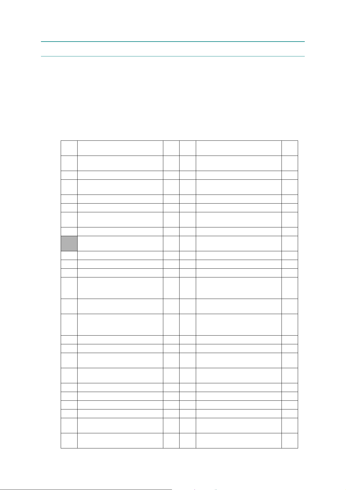
2.1 Error indication
The error codes
shaded
in the table below are recoverable errors if you follow the User Check items.
Error
codes
Replacement time of the drum
50
unit
Problem
Refer
to:
Error
codes
Problem
1-7 7B Main PCB failure 1-13
Refer
56 Fuser cover opened 1-8 7D Dirt on drum unit 1-14
Fuser unit failure
58
(Stand ready in the given time)
1-8 7F Fax paper setting mismatch 1-14
59 Fuser unit failure 1-8 80 Fax paper size is small 1-14
5A
HVPS PCB ASSY failure
New toner detecting lever
5B
malfunction
63
Toner cartridge is at the end of life.
Toner of the toner cartridge is
67
low
1-9 84
Paper jam in rear of the machine
1-16
1-9 88 Paper jam inside the machine 1-16
1-10 8A Paper jam in Tray 1 (T1) 1-17
1-7 8D Paper jam near paper eject tray 1-17
68 Fuser unit failure 1-11 9F Paper empty 1-18
69 Fuser unit failure 1-11 A1 Front cover open 1-18
6A Fuser unit failure 1-11 A2 Document is too long. 1-18
Document rear sensor is not
6B Fuser unit failure 1-11 A3
turned on when feeding the
1-19
document.
6C Fuser unit failure 1-11 A5
Fax scanning error
(First warning only)
1-19
Fax scanning error (The second
6D Fuser unit failure 1-11 A6
warning that the same error with
1-19
A5 occurs again)
6E Fuser unit failure 1-11 AD DMA transfer error 1-19
6F Fuser unit failure 1-11 AF FB unit home position failure 1-20
71 Polygon motor failure 1-12 B0
BD beam detecting sensor
72
malfunction
1-12 B7 Detection error of scanner 1-20
Harness for scanning is not
connected correctly.
1-20
75 Machine cooling down inside 1-7 B9 Scanning light adjustment error. 1-20
76 Fuser unit failure 1-12 BB White level data error 1-21
77 Fuser unit failure 1-12 E6 NVRAM error on main PCB 1-21
78 Fuser unit failure 1-13 EC Fan performance malfunction 1-21
No detection of the internal
79
temperature thermistor
No detection of main motor lock
7A
signal
1-13 F8 Battery connection failure 1-21
1-13 F9
Maintenance mode 74 Non-
decision
1-22
to:
1-6
Confidential
Page 25

2.2 Error Code Cause and Remedy
2.2.1 Recoverable User Check Errors
These errors are recoverable by following the message indicated on the LCD or following the
items indicated in User Check
■ Error code 67
Toner Low
Prepare New Toner Cartridge
The toner of the toner cartridge is low. (The toner sensor delects the nearly empty.)
User Check
• Prepare a new toner cartridge. If the toner is empty, Replace it.
■ Error code 75
Cooling Down
Wait for a while
The machine is cooling down inside for protection.
The machine indicates "Cooling Down" in one of the conditions below.
.
(1) The temperature inside the machine is too high.
(2) Both ends of the heat roller are at different temperatures.
(3) The paper media is replaced with different Paper size media.
User Check
• After having passed for a while with having turned the power supply on.
2.2.2 Service Call Error
Check the User Check items first. If the same problem occurs follow each procedure in the
order of the number described in the Step column in the table below.
■ Error code 50
Drum End Soon
Replacement time of the drum unit. (The drum counter reached the upper limit.)
User Check
• Replace the drum unit with a new one.
Step Cause Remedy
1 Main PCB failure Replace the main PCB ASSY.
1-7
Confidential
Page 26
■ Error code 56
Cover is Open
Close the Fuser Cover.
Fuser cover opened
User Check
• Check if the Fuser cover is closed correctly.
Step Cause Remedy
1
2 Eject actuator failure Re-assemble the eject actuator
3 Eject sensor PCB ASSY failure Replace the eject sensor PCB ASSY.
4 Main PCB failure Replace the main PCB ASSY.
Harness connection failure of back
cover switch ASSY
Check the harness connection of the back
cover switch ASSY and reconnect it.
■ Error code 58
Fuser Error
Turn the power off, then on again. Leave the machine for 15 min.
Error code 59
Self-Diagnostic
Will Automatically Restart within 15 minutes.
If the same error is detected again 15 minutes later, the message below is indicated.
Print Unable 6A
See Troubleshooting and routine maintenance chapter in User’s Guide.
Fuser unit failure *It occurs with either of 68, 69, 6A, 6B, 6C, 6D, 6E, 6F, 76 and 78.
Step Cause Remedy
Harness connection failure
1
2 Fuser unit failure Replace the fuser unit.
3 LVPS PCB failure Replace the LVPS PCB unit.
4 Eject sensor PCB ASSY failure Replace the eject sensor PCB ASSY.
5 Main PCB failure Replace the main PCB ASSY.
between fuser unit and eject
sensor PCB
Check the harness connection between the
fuser unit and eject sensor PCB, and
reconnect it.
1-8
Confidential
Page 27

■ Error code 5A
Print Unable 5A
See Troubleshooting and routine maintenance chapter in User’s Guide.
HVPS PCB failure (Developing bias voltage failure)
Step Cause Remedy
HVPS PCB ASSY harness
1
2 HVPS PCB failure Replace the HVPS PCB ASSY.
3 Main PCB failure Replace the main PCB ASSY.
connection failure
■ Error code 5B
Cartridge Error
Put the Black Toner Cartridge back in.
New toner detection lever malfunction
User Check
• Check if the toner cartridge is attached.
Step Cause Remedy
1
2 New toner detection switch failure Replace the new toner harness ASSY.
3 Main PCB failure Replace the main PCB ASSY.
New toner detection switch
harness connection failure
Check the harness connection between the
HVPS PCB and main PCB. Then,
reconnect them.
Check the harness connection of the new
toner detection switch. Then, reconnect it.
1-9
Confidential
Page 28

■ Error code 63
Toner Life End
Replace Toner Cartridge.
Toner cartridge is at the end of its life.
(The toner sensor detects the nearly empty, or the drum counter reached the upper limit.)
User Check
• Gently shake the toner cartridge from side to side and install it again.
• Replace the toner cartridge.
Step Cause Remedy
Harness connection failure of new
toner sensor harness ASSY.
1
Check the sensor performance following
the procedure described in "Maintenance
mode 32". If any problem occurs, check the
harness connection of the new toner
sensor harness ASSY, then reconnect it.
Harness connection failure of
toner sensor PCB unit ASSY.
2
Check the sensor performance following
the procedure described in "Maintenance
mode 32". If any problem occurs, check the
harness connection of the toner sensor
PCB unit ASSY, then reconnect it.
3
4
New toner sensor harness ASSY
failure (Toner empty)
Toner sensor PCB unit ASSY
failure.
Replace the new toner sensor harness
ASSY.
Replace the toner sensor PCB unit ASSY.
5 Main PCB failure Replace the main PCB ASSY.
1-10
Confidential
Page 29

■ Error code 68
Print Unable 68
See Troubleshooting and routine maintenance chapter in User’s Guide.
Fuser unit failure (The side thermistor detects higher temperature than the specified value.)
Error code 69
Print Unable 69
See Troubleshooting and routine maintenance chapter in User’s Guide.
Fuser unit failure (The side thermistor detects lower temperature than the specified value.)
Error code 6A
Print Unable 6A
See Troubleshooting and routine maintenance chapter in User’s Guide.
Fuser unit failure (The side thermistor does not detect 60°C within the specified time.)
Error code 6B
Print Unable 6B
See Troubleshooting and routine maintenance chapter in User’s Guide.
Fuser unit failure (The center thermistor does not detect 100°C within the specified time.)
Error code 6C
Print Unable 6C
See Troubleshooting and routine maintenance chapter in User’s Guide.
Fuser unit failure (The center thermistor detects higher temperature than the specified value.)
Error code 6D
Print Unable 6D
See Troubleshooting and routine maintenance chapter in User’s Guide.
Fuser unit failure (The center thermistor detects lower temperature than the specified value.)
Error code 6E
Print Unable 6E
See Troubleshooting and routine maintenance chapter in User’s Guide.
Fuser unit failure (The center thermistor does not detect temperature rising within the specified time.)
Error code 6F
Print Unable 6F
See Troubleshooting and routine maintenance chapter in User’s Guide.
Fuser unit failure (The center and side thermistors detect extremely high temperature.)
Step Cause Remedy
1
2 Fuser unit failure Replace the fuser unit.
3 LVPS PCB unit failure Replace the LVPS PCB unit.
4 Main PCB failure Replace the main PCB ASSY.
Fuser unit harness connection
failure
1-11
Check the harness connection of the fuser
unit and reconnect it.
Confidential
Page 30
■ Error code 71
Print Unable 71
See Troubleshooting and routine maintenance chapter in User’s Guide.
Laser unit Polygon mirror motor failure
(Cannot detect the period signal of the polygon mirror motor.)
Error code 72
Print Unable 72
See Troubleshooting and routine maintenance chapter in User’s Guide.
BD beam detect sensor malfunction
Step Cause Remedy
1
2 Laser unit failure Replace the laser unit.
3 Main PCB failure Replace the main PCB ASSY.
Laser unit harness connection
failure
Check the two harness connections of the
laser unit and reconnect them.
■ Error code 76
Print Unable 76
See Troubleshooting and routine maintenance chapter in User’s Guide.
Fuser unit failure (The center thermistor detects rapidly rising temperature.)
Step Cause Remedy
1
2 Fuser unit failure Replace the fuser unit.
Fuser unit harness connection
failure
Check the harness connection of the fuser
unit and reconnect it.
■ Error code 77
Print Unable 77
See Troubleshooting and routine maintenance chapter in User’s Guide.
Fuser error code failure (The error history of the fuser unit is deleted.)
Step Cause Remedy
1 Fuser unit failure Replace the fuser unit.
2 Main PCB failure Replace the main PCB ASSY.
1-12
Confidential
Page 31

■ Error code 78
Print Unable 78
See Troubleshooting and routine maintenance chapter in User’s Guide.
Fuser unit failure (The temperature sensor of the fuser unit is broken.)
Step Cause Remedy
1 Fuser unit failure Replace the fuser unit.
2 Main PCB failure Replace the main PCB ASSY.
■ Error code 79
Print Unable 79
See Troubleshooting and routine maintenance chapter in User’s Guide.
No detection of the internal temperature thermistor.
Step Cause Remedy
1
2
3 Main PCB failure Replace the main PCB ASSY.
Harness connection failure of
internal temperature thermistor
Internal temperature thermistor
failure
Check the harness connection of the internal
temperature thermistor, and reconnect it.
Replace the internal temperature
thermistor.
■ Error code 7A
Print Unable 7A
See Troubleshooting and routine maintenance chapter in User’s Guide.
No detection of the main motor lock signal.
Step Cause Remedy
1 Main motor failure Replace the main motor ASSY.
2 Main PCB failure Replace the main PCB ASSY.
■ Error code 7B
Print Unable 7B
See Troubleshooting and routine maintenance chapter in User’s Guide.
Main PCB failure
Step Cause Remedy
1 Main PCB failure Replace the main PCB ASSY.
1-13
Confidential
Page 32

■ Error code 7D
Drum Error
Open the front cover, then clean the corona wire of drum unit
according to the label.
Dirt on drum unit
User Check
• Clean the corona wire of the drum unit.
• Replace the drum unit with a new one.
Step Cause Remedy
1
2 HVPS PCB failure Replace the HVPS PCB ASSY.
3 Main PCB failure Replace the main PCB ASSY.
Dirt or dust on drum unit
electrodes
Clean the electrodes on the drum unit.
(Refer to Fig. 1-1.)
■ Error code 7F
Size mismatch
Fax received. Set correct paper size in menu.
Fax paper setting mismatch (The setting paper becomes besides the A4/Letter/Legal/Folio.)
User Check
• Set the A4/Letter/Legal/Folio using the paper size setting in menu.
Step Cause Remedy
1 Main PCB failure Replace the main PCB ASSY.
■ Error code 80
Size mismatch
Reload correct paper, then press Start.
Fax paper size is incorrect
(The registration rear sensor detected the paper that is smaller than the letter size.)
User Check
• Set the paper of A4 or LETTER-size on the paper tray.
Step Cause Remedy
1
Registration front actuator
catching in some position
1-14
Re-assemble the registration front actuator.
Confidential
Page 33

■ Electrodes location on the drum unit
Side surface of
Drum unit
Fig. 1-1
■ Electrodes location on the machine
Side surface of
Frame L ASSY inside
Fig. 1-2
1-15
Confidential
Page 34

■ Error code 84 (Jam Rear)
Jam Rear
Open the Back Cover and remove the jammed paper.
Paper jam in the rear of the machine (It is detects by the eject sensor)
Error code 88 (Jam Inside)
Jam Inside
Open the Front Cover, pull out the Drum Unit completely and remove
the jammed paper.
Paper jam inside the machine (It is detects by the registration rear sensor)
User Check
• Check if the paper is jammed. If there is any jammed paper, remove it.
Step Cause Remedy
Harness connection failure of
1
registration front sensor PCB ASSY,
registration rear sensor PCB ASSY
or paper eject sensor PCB ASSY
Registration front actuator,
2
registration rear actuator or paper
eject actuator not operating smoothly
or catching in some position.
Check the harness connections of the
registration front sensor PCB ASSY,
registration rear sensor PCB ASSY and paper
eject sensor PCB ASSY, and reconnect them.
Ensure smooth operation of the registration
front actuator, registration rear actuator or
paper eject actuator and ensure they are
not catching in any positions.
Paper eject sensor PCB failure Check the sensor performance following
3
the procedure described in "Maintenance
mode 32". If any problem occurs, replace
the eject sensor PCB ASSY.
Registration front sensor PCB
4
failure
Check the sensor performance following
the procedure described in "Maintenance
mode 32". If any problem occurs, replace
the registration front sensor PCB ASSY.
Registration rear sensor PCB
5
failure
Check the sensor performance following
the procedure described in "Maintenance
mode 32". If any problem occurs, replace
the registration rear sensor PCB ASSY.
6
Registration ground spring failure Re-assemble the registration ground
spring. (Refer to Fig. 1-3.)
7 Main PCB failure Replace the main PCB ASSY.
Registration ground spring
Fig. 1-3
1-16
<Main frame R ASSY>
Confidential
Page 35

■ Error code 8A
Jam Tray
Remove the jammed paper from Tray.
Paper jam in Tray 1 (T1) (It is detects by the registration front sensor)
User Check
• Check if the paper is jammed in the tray. If jammed, remove it.
• Adjust the paper guide corresponding to the paper size.
• Check if too much paper is loaded in the tray.
Step Cause Remedy
Harness connection failure of
1
2 Paper feed roller worn out Replace the paper feed roller.
3
4 Main PCB failure Replace the main PCB ASSY.
registration front sensor PCB
ASSY
Registration front sensor PCB
failure
Check the harness connection of the
registration front sensor PCB ASSY in the
appropriate tray, and reconnect it.
Check the sensor performance following
the procedure described in "Maintenance
mode 32". If any problem occurs, replace
the registration front sensor PCB ASSY.
■ Error code 8D
Cover is open
Open the Back cover and remove the jammed paper, or close the
Fuser Cover.
Paper jam near paper eject tray (When power on, it is detects by the eject sensor.)
User Check
• Remove the jammed paper near the paper eject tray or the back cover.
• Close the fuser cover.
Step Cause Remedy
Paper eject actuator not operating
1
2 Eject sensor PCB ASSY failure Replace the eject sensor PCB ASSY.
3 Main PCB failure Replace the main PCB ASSY.
smoothly catching in some
position.
1-17
Re-assemble the paper eject actuator.
Ensure the paper eject sensor operates
smoothly.
Confidential
Page 36

■ Error code 9F
No paper
Reload paper, then press start.
Paper empty (It is detects by the registration front sensor)
User Check
• Replenish the paper in the paper tray.
Step Cause Remedy
1
2
3
4 Main PCB failure Replace the main PCB ASSY.
Registration front actuator
catching in some position
Registration front sensor PCB
harness connection failure
Registration front sensor PCB
failure
■ Error code A1
Cover is open
Close the Front Cover.
Front cover open
User Check
• Close the front cover.
Step Cause Remedy
1
Harness connection failure of
cover sensor harness ASSY.
Re-assemble the registration front actuator.
Check the harness connection of the
registration front sensor PCB and
reconnect it.
Replace the registration front sensor PCB.
Check the harness connection of the cover
sensor harness ASSY, and reconnect it.
2
3 Main PCB failure Replace the main PCB ASSY.
Cover sensor harness ASSY
failure
Replace the cover sensor harness ASSY.
■ Error code A2
Document Jam.
Clear the scanner jam, then press the Stop Key.
The document is too long. (During scanning, 90 cm or longer of a document is detected.)
User Check
• Check if the document is jammed in the ADF. If it is jammed, remove it.
Step Cause Remedy
Document rear actuator not
1
operating smoothly or catching in
some position.
Ensure smooth operation and that there is
no catching of document rear actuator.
1-18
Confidential
Page 37

■ Error code A3
Document Jam.
Clear the scanner jam, then press the Stop Key.
Document rear sensor is not turned on when feeding the document.
User Check
• Check if the document is jammed in the ADF. If it is jammed, remove it.
Step Cause Remedy
Document rear actuator not
1
2 Document rear sensor failure. Replace the document rear sensor.
3 ADF motor failure Replace the ADF motor.
operating smoothly or catching in
some position.
Ensure smooth operation and that there is
no catching of document rear actuator.
■ Error code A5
Scan Unable A5
Remove the original document. Turn the power off, then on again.
Fax scanning error (First warning only)
Step Cause Remedy
1
Scanning failure Turn the power switch off and on. Then, try
scanning again.
■ Error code A6
Scan Unable A6
Remove the original document. Turn the power off, then on again.
Fax scanning error (After the A5 error occurs, the same problem occurs again even after
turning the power off and on.)
Step Cause Remedy
1 FB unit failure Replace the FB unit.
2 Main PCB failure Replace the main PCB ASSY.
■ Error code AD
Scan Unable AD
Remove the original document, Turn the power off, then on again.
DMA transfer error
Step Cause Remedy
1 FB unit failure Replace the FB unit.
2 Main PCB failure Replace the main PCB ASSY
1-19
Confidential
Page 38
■ Error code AF
Scan Unable AF
Remove the original document. Turn the power off, then on again.
FB unit home position failure
Step Cause Remedy
1 FB unit failure Replace the FB unit.
2 Main PCB failure Replace the main PCB ASSY.
■ Error code B0
Scanner Error
Harness for scanning is not connected correctly.
* This error is indicated on the LCD in the maintenance mode.
Step Cause Remedy
1
2 Scanner harness broken Replace the FB unit.
3 Main PCB failure Replace the main PCB ASSY.
Scanner harness not connected
correctly.
Reconnect the scanner harness correctly.
■ Error code B7
Scanner Error
Detection error of scanner (Scanning reference voltage adjustment malfunction.)
* This error is indicated on the LCD in the maintenance mode.
Step Cause Remedy
1 FB unit failure Replace the FB unit.
2 Main PCB failure Replace the main PCB ASSY.
■ Error code B9
Scanner Error
Scanning light adjustment error is detected.
* This error is indicated on the LCD in the maintenance mode.
Step Cause Remedy
1 FB unit failure Replace the FB unit.
2 Main PCB failure Replace the main PCB ASSY.
1-20
Confidential
Page 39

■ Error code BB
Scanner Error
White level data error
* This error is indicated on the LCD in the maintenance mode.
Step Cause Remedy
1 FB unit failure Replace the FB unit.
2 Main PCB failure Replace the main PCB ASSY.
■ Error code E6
Init Unable E6
See Troubleshooting and routine maintenance chapter in User’s Guide.
NVRAM error on main PCB
Step Cause Remedy
1 Main PCB failure Replace the main PCB ASSY.
■ Error code EC
Print Unable EC
See Troubleshooting and routine maintenance chapter in User’s Guide.
Fan performance malfunction
Step Cause Remedy
1
2 Fan motor failure Replace the fan motor.
3 Main PCB failure Replace the main PCB ASSY.
Harness connection failure of fan
motor
Check the harness connection of the fan
motor, and reconnect it.
■ Error code F8
Machine Error F8
Battery connection failure
Step Cause Remedy
1 Battery harness connection failure Reconnect the battery harness.
2 Battery exhausted Replace the battery.
3 Main PCB failure Replace the main PCB ASSY.
1-21
Confidential
Page 40

■ Error code F9
Machine Error F9
Maintenance mode 74 Non-decision (Inputting omission of the customizing code.)
Step Cause Remedy
Turn the power off, when the
1
Maintenance mode 74 is in
Implement the Maintenance mode 74
again.
progress.
1-22
Confidential
Page 41

3. PAPER FEEDING PROBLEMS
Problems related to paper feeding are end user recoverable if following the User Check
items. If the same problem occurs again, follow each procedure in the order of the number
described in the Step column in the tables below.
3.1 No Feeding
Step Cause Check
Edge actuator
1
catching in some
position
Roller holder
2
ASSY catching in
some position
Registration front
sensor failure
3
Paper feeding kit
failure
4
Pressure plate
5
gear damage
T1 solenoid failure Does the T1 solenoid
6
T1 solenoid Circuit
of the high-voltage
7
power supply PCB
broken
Does the edge actuator
move smoothly? No
Does the roller holder
ASSY move smoothly? Yes
Is the problem solved
after replacing the
registration front sensor
PCB ASSY?
Is the surface of the
separation pad or the
pickup roller dirty or worn
out?
Is the pressure plate gear
damaged?
work correctly?
Is the problem solved
after replacing the highvoltage power supply
PCB ASSY?
Result
Ye s
Ye s
Ye s
No
Ye s
Remedy
Re-assemble the edge
actuator and ensure
smooth operation.
Re-assemble the roller
holder ASSY and ensure
smooth operation.
Replace the registration
front sensor PCB ASSY.
1) Clean the surface of
the separation pad or
pickup roller.
2) Replace the separation
pad or pickup roller.
Replace the paper tray.
Replace the T1 solenoid
Replace the high-voltage
power supply PCB ASSY.
Main PCB failure Is the problem solved
8
Main motor failure Is the problem solved
9
3.2 Double Feeding
Step Cause Check
Paper feeding kit
1
is abrasion
after replacing the main
PCB ASSY?
after replacing the drive
sub ASSY?
Is the surface of the
separation pad worn out?
Ye s
Ye s
Result
Ye s
Replace the main PCB
ASSY.
Replace the drive sub
ASSY.
Remedy
Replace the paper
feeding kit.
1-23
Confidential
Page 42

3.3 Paper Jam
■ Paper jam in the paper tray and front cover
Step Cause Check
Registration front
actuator/edge
1
actuator catching
in some position
Registration front
sensor PCB
(registration front
actuator/edge
2
actuator failure)
Registration
3
solenoid failure
Toner sensor PCB
4
failure
High-voltage
power supply PCB
5
failure
Registration
6
ground spring
loose
Does the registration front
actuator/edge actuator
move smoothly?
Does the registration front
sensor move smoothly?
(Check it following the
procedure described in
"Operational Check of
Sensors (Function code
32)" in Chapter 5)
Is the problem solved
after replacing the
registration solenoid?
Is the problem solved
after replacing the toner
sensor PCB?
Is the problem solved
after replacing the Highvoltage power supply
PCB ASSY?
Is the registration ground
spring fitted correctly? No
Result
No
No
Ye s
Ye s
Ye s
Remedy
Re-assemble the
registration front actuator/
edge actuator and ensure
smooth operation.
Replace the registration
front sensor PCB ASSY.
Replace the registration
solenoid.
Replace the toner LED
PCB.
Replace the High-voltage
power supply PCB ASSY.
Fit the registration ground
spring correctly.
(Refer to Fig. 1-3.)
Main PCB failure Is the problem solved
7
after replacing the Main
PCB ASSY?
■ Paper jam in the back cover and paper eject section
Step Cause Check
Foreign object
1
around fuser unit
Paper eject
2
actuator failure
Fuser cover ASSY
3
loose
Outer chute ASSY
4
loose
Eject roller 2
malfunction
5
Paper eject sensor
6
PCB failure
Is there a foreign object
around the fuser unit?
Does the paper eject
actuator move smoothly?
Is it damaged?
Is the fuser cover ASSY
fitted correctly?
Is the outer chute ASSY
fitted correctly?
Is each pinch roller of the
inner chute ASSY
attached to each eject
roller 2 of top cover ASSY
properly?
Is the problem solved
after replacing the paper
eject sensor PCB?
Result
Replace the Main PCB
Ye s
ASSY.
Remedy
Remove the foreign
Ye s
object.
Replace the paper eject
No
actuator.
Fit the fuser cover ASSY
No
correctly.
Fit the outer chute ASSY
No
fitted correctly.
Replace the inner chute
ASSY.
No
Replace the paper eject
Ye s
sensor PCB.
1-24
Confidential
Page 43

3.4 Dirt on Paper
User Check
• Check if the paper is loaded into the paper tray correctly.
• Turn over the stack of paper in the paper tray, or try rotating the paper 180° in the paper
tray.
Step Cause Check
Fuser unit dirty Is there dirt around the
1
3.5 Wrinkles or creases
User Check
• Check if the paper is loaded into the paper tray correctly.
• Turn over the stack of paper in the paper tray, or try rotating the paper 180° in the paper
tray.
Step Cause Check
Fuser unit dirty Is there dirt around the
1
Fuser unit failure Is the problem solved if
2
entrance of the fuser
unit?
Is the pressure roller
ASSY dirty?
entrance of the fuser
unit?
new fuser unit is
replaced?
Result
Ye s
Ye s
Result
Ye s
Ye s
Remedy
Clean the entrance of the
fuser unit.
Clean the pressure roller
ASSY.
Remedy
Clean the entrance of the
fuser unit.
Replace the fuser unit.
3.6 Waves in the paper / folds in the paper at the eject roller 2
User Check
• Check that the problem is solved if new paper is used.
Step Cause Check
Foreign object
1
around eject roller 2
Eject roller 2
2
failure
Is there a foreign object
around the eject roller 2?
Is the problem solved
after replacing the new
eject roller 2?
Result
Ye s
Ye s
Remove the foreign object.
Replace the top cover
ASSY.
Remedy
1-25
Confidential
Page 44

3.7 Curl in the paper
1
1
Step Cause Check
Fuser unit
pressure is high
1
Is the problem solved
after replacing the
position of the pressure
Result
Ye s
Remedy
Replace the position of the
pressure roller.
roller?
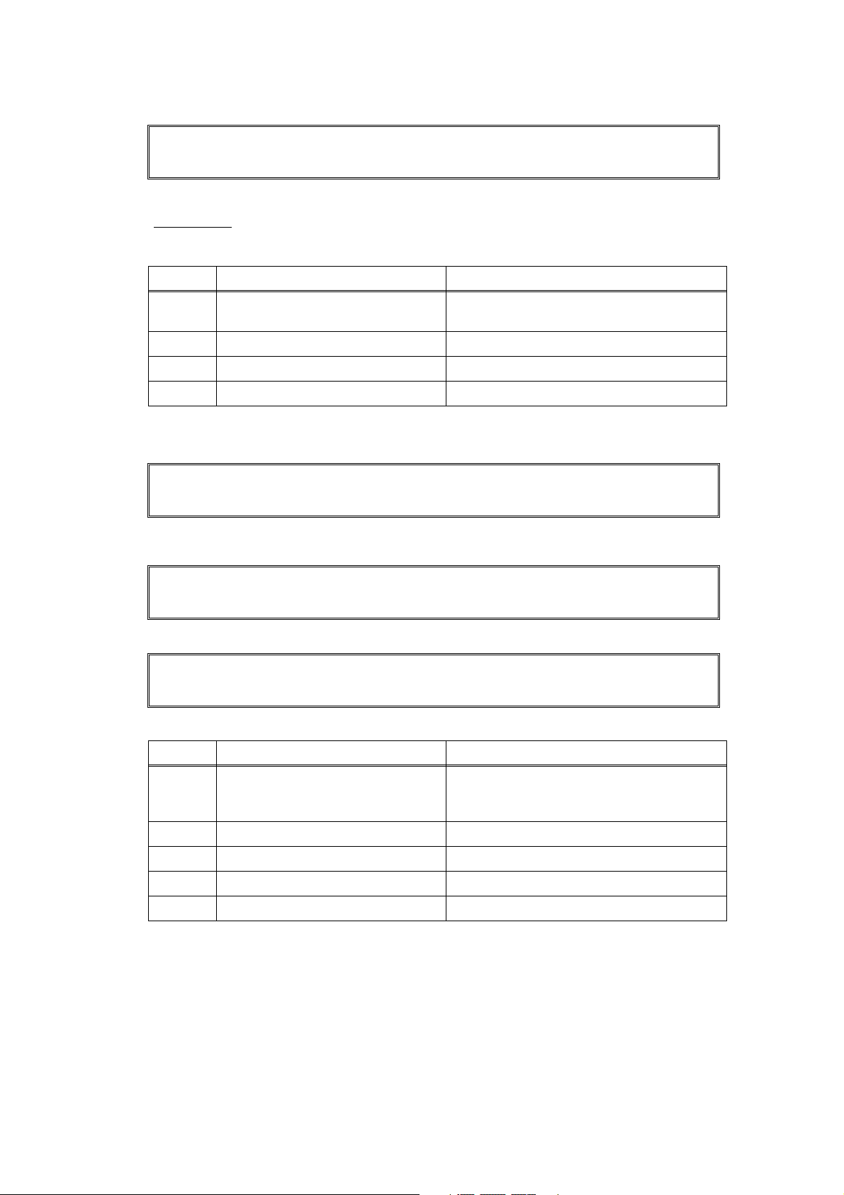
(1) Turn the Nip release lever of right and left to the direction of the arrow.
(2) Hold and turn the PR stopper plate of right and left.
(3) Print it again, and check that the curl in the paper occurs.
(4) When there seems to be still the curl, replace the position of the pressure roller again.
2
1
NIP RELEASE LEVER
NIP RELEASE LEVER
PRESSURE ROLLER
2
PR STOPPER PLATE
1
Fig. 1-4
1-26
Confidential
Page 45

4. TROUBLESHOOTING OF DOCUMENT FEEDING
Problems related to document feeding are end user recoverable if following the User Check
items. If the same problem occurs again, follow each procedure in the order of the number
described in the step column in the tables below.
4.1 No Feeding
User Check
• Check if the document is inserted correctly to the depths of the ADF unit. (If the
document is inserted, the LCD indication is changed.)
Step Cause Check
Document front
actuator not
1
operating
smoothly or
catching
Foreign object
2
around paper
feed roller
Paper feed roller
3
failure
ADF sensor PCB Is the problem solved by
4
ADF motor
5
failure
Drive frame
6
ASSY failure
Main PCB failure Is the problem solved
7
Does document front
actuator move
smoothly? No
Is there a foreign object
around the paper feed
roller?
Is the surface of the
paper feed roller worn
out?
replacing the ADF
sensor PCB?
Is the problem solved by
replacing the ADF
motor?
Is the problem solved by
replacing the drive
frame ASSY?
after replacing the main
PCB ASSY?
Result
Ye s
Ye s
Ye s
Ye s
Ye s
Ye s
Remedy
Re-assemble document
front actuator.
Remove the foreign object.
Replace the separate roller
shaft ASSY.
Replace the ADF sensor
PCB.
Replace the ADF motor.
Replace the drive frame
ASSY.
Replace the main PCB
ASSY.
4.2 Double feeding
Step Cause Check
Separation
1
rubber failure
Is the surface of the
separation rubber worn
out?
1-27
Result
Ye s
Remedy
Replace the separation
rubber.
Confidential
Page 46

4.3 Paper Jam
User Check
• Check if the paper is loaded into the ADF tray correctly.
• Check if do not use the crimpy or torn paper.
Step Cause Check
Document rear
actuator not
1
operating
smoothly or
catching
Foreign object
around feed
2
roller / paper
eject roller
actuator
Pinch roller of
3
feed roller failure
Pinch roller of
4
paper eject roller
failure
Pressure roller
5
film unstick
ADF sensor PCB Is the problem solved by
6
ADF motor
7
failure
Does document rear
actuator move
smoothly? No
Is there a foreign object
around the feed roller /
paper eject roller
actuator?
Is pinch roller of feed
roller remove?
Is pinch roller of paper
eject roller remove? Yes
Does pressure roller film
unstick?
replacing the ADF
sensor PCB?
Is the problem solved by
replacing the ADF
motor?
Result
Ye s
Ye s
Ye s
Ye s
Ye s
Remedy
Re-assemble the
document rear actuator.
Remove the foreign object.
Re-assemble the pinch
roller of the feed roller.
Re-assemble the pinch
roller of the paper eject
roller.
Replace the pressure roller
film.
Replace the ADF sensor
PCB.
Replace the ADF motor.
Drive frame
8
ASSY failure
Main PCB failure Is the problem solved
9
Is the problem solved by
replacing the drive
frame ASSY?
after replacing the main
PCB ASSY?
Replace the drive frame
Ye s
ASSY.
Replace the main PCB
Ye s
ASSY.
1-28
Confidential
Page 47

5. IMAGE DEFECT TROUBLESHOOTING (Defect Of the Print)
5.1 Image Defect Examples
Light
Image distortion
Black vertical streaks
in a light background
White spots
Faulty registration
All black
Black horizontal
stripes
Black spots
Dark
Dirt on the back of paper
White vertical
streaks
Black band
White horizontal
streaks
Downward fogging
of solid color
Poor fixing
Vertical streaks
Completely blank
Faint print
Horizontal lines
Ghost
Fogging
CAUTION:
The image defect at the copy might have the cause in the scanning.
When the failure does not reproduce by print the test pattern “MAINTENANCE 09” or PC
print, refer to "6. TROUBLESHOOTING OF SCANNIG".
5.2 Diameter of Rollers
Image defects which appear periodically may be caused by failure of a roller. Specify the
cause referring to the diameter of the rollers or pitch which appears in the image as shown in
the table below.
No. Parts name
1 Develop roller
2 Exposure drum
3 Heat roller in the fuser unit
4 Pressure roller ASSY in the fuser unit
Fig. 1-5
1-29
Diameter
The pitch which
appears in the image
Ø20.0 mm 41.0 mm
Ø24.0 mm 75.0 mm
Ø25.0 mm 78.5 mm
Ø25.0 mm 78.5 mm
Confidential
Page 48

5.3 Troubleshooting Image Defect
Image defect related problems are end user recoverable if following the User Check items. If
the same problem occurs, follow each procedure in the order of the number described in the
Step column in the tables below.
■ Light
User Check
• Check the machine's environment. High temperature and high
humidity conditions can cause this problem.
• If the whole page is light, toner save mode may be on.
• Replace the toner cartridge or drum unit with a new one.
Step Cause Check
Dirt on exposure
1
drum electrode
Dirt on scanner
2
windows of the
laser unit
Toner sensor
failure
3
4
Between the
HVPS PCB/Main
5
PCB connection
failure
Are the electrodes of the
drum unit and machine
body dirty?
Is the scanner windows
of the laser unit dirty? Yes
After replacing the toner
cartridge with a new
one, does the same
problem occur even
after printing several
pages?
Does the machine start
printing even after
removing the toner
cartridge from the drum
unit? Yes
Is the harness of the
HVPS PCB ASSY and
main PCB ASSY
connected correctly?
Result
Ye s
Ye s
No
Remedy
Clean both electrodes.
(Refer to Fig. 1-1, Fig. 1-2.)
Wipe the dirt off with a soft,
clean, lint free cloth.
Replace the toner
cartridge.
Clean the toner sensor.
(receiving light side)
Check the harness
connection of the toner
LED PCB ASSY.
(luminescence side)
Replace the toner sensor
PCB ASSY or toner LED
PCB ASSY.
Reconnect the harness of
the HVPS PCB ASSY and
main PCB ASSY.
HVPS PCB
6
failure
Main PCB failure Is the problem solved
7
Laser unit failure Is the problem solved
8
Is the problem solved
after replacing the
HVPS PCB ASSY?
after replacing the main
PCB ASSY?
after replacing the laser
unit?
1-30
Replace the HVPS PCB
Ye s
ASSY.
Replace the main PCB
Ye s
ASSY.
Replace the laser unit.
Ye s
Confidential
Page 49

■ Faulty registration
User Check
• Check that the appropriate media type is selected in the
printer driver.
Step Cause Check
Registration rear
actuator catching
1
in some position
Does the registration
rear actuator move
smoothly?
■ Dark
User Check
• Check the machine's environment. High temperature and high
humidity conditions can cause this problem.
• Replace the drum unit with a new one.
• Replace the toner cartridge with a new one.
Step Cause Check
The developing
bias voltage
1
failure
HVPS PCB
2
failure
Is the problem solved
after resetting the
developing bias
counter?
Is the problem solved
after replacing the
HVPS PCB ASSY?
Result
No
Result
Ye s
Ye s
Remedy
Re-assemble the
registration rear actuator
and ensure smooth
operation.
Remedy
Reset the developing bias
counter. (Refer to "2.2
Resetting the developing
bias voltage counter" in
Chapter 5)
Replace the HVPS PCB
ASSY.
Main PCB failure Is the problem solved
3
after replacing the main
PCB ASSY?
Replace the main PCB
Ye s
ASSY.
1-31
Confidential
Page 50

■ Poor fixing
User Check
• Replace the drum unit with a new one.
• Replace the toner cartridge with a new one.
Step Cause Check
Fuser unit
pressure is high
1
Fuser unit failure Is the problem solved
2
LVPS PCB failure Is the problem solved
3
HVPS PCB
4
failure
Main PCB failure Is the problem solved
5
Is the problem solved
after replacing the
position of the pressure
roller?
after replacing the fuser
unit?
after replacing the LVPS
PCB unit?
Is the problem solved
after replacing the
HVPS PCB ASSY?
after replacing the main
PCB ASSY?
■ Completely blank
User Check
• Replace the drum unit with a new one.
• Replace the toner cartridge with a new one.
Result
Ye s
Ye s
Ye s
Ye s
Ye s
Remedy
Replace the position of the
pressure roller.
(Refer to Fig. 1-4.)
Replace the fuser unit.
Replace the LVPS PCB
unit.
Replace the HVPS PCB
ASSY.
Replace the main PCB
ASSY.
Step Cause Check
Developing bias
voltage
1
conduction
failure
Scanner harness
of the laser unit
2
connection
failure
Laser unit failure Is the problem solved
3
HVPS PCB
4
failure
Main PCB failure Is the problem solved
5
Are the electrodes on
the drum unit and
machine body dirty?
Is the scanner harness
of the laser unit
connected securely?
after replacing the laser
unit?
Is the problem solved
after replacing the
HVPS PCB ASSY?
after replacing the main
PCB ASSY?
1-32
Result
Ye s
No
Ye s
Ye s
Ye s
Remedy
Clean both electrodes.
(Refer to Fig. 1-1, Fig. 1-2.)
Reconnect the scanner
harness of the laser unit.
Replace the laser unit.
Replace the HVPS PCB
ASSY.
Replace the main PCB
ASSY.
Confidential
Page 51

■ Image distortion
Step Cause Check
1
Laser unit not
assembled
correctly
Is the laser unit
assembled into the
machine securely?
(Check if there is no
gap.)
Incorrect
radiation angle of
scanner diode of
2
laser unit.
Is the problem solved
after replacing the laser
unit?
Scanner motor
rotation failure
Main PCB failure Is the problem solved
3
after replacing the main
PCB ASSY?
Result
No
Ye s
Ye s
Remedy
Assemble the laser unit
correctly and secure the
screw.
Replace the laser unit.
Replace the main PCB
ASSY.
1-33
Confidential
Page 52

■ All black
Step Cause Check
1
Corona wire
failure
Are the electrodes on
the drum unit and
machine body dirty?
2
Under FG wire
3
not assembled
Is the corona wire
damaged?
Is the under FG wire
connected securely? No
correctly
Scanner harness
of the laser unit
4
connection
Is the scanner harness
of the laser unit
connected securely?
failure
FG harness
ASSY connection
5
failure
Is the FG harness ASSY
between the laser unit
and main PCB ASSY
connected securely?
6
HVPS PCB
failure
Is the problem solved
after replacing the
HVPS PCB ASSY?
Main PCB failure Is the problem solved
7
after replacing the main
PCB ASSY?
Result
Ye s
Ye s
No
No
Ye s
Ye s
Remedy
Clean both electrodes.
Replace the drum unit.
Re-assemble the under FG
wire.
Reconnect the scanner
harness of the laser unit.
Reconnect the FG harness
ASSY between the laser
unit and main PCB ASSY
securely.
Replace the HVPS PCB
ASSY.
Replace the main PCB
ASSY.
Laser unit failure Is the problem solved
8
after replacing the laser
unit?
Replace the laser unit.
Ye s
1-34
Confidential
Page 53

■ Dirt on the back of paper
Step Cause Check
Scratch or Dirt
on the fuser unit
1
Scratch or Dirt in
2
the paper feed
system
Is the pressure roller
ASSY dirty?
Is any other area in the
machine dirty?
Is the paper feed system
dirty? Yes
■ Vertical streaks
User Check
• This problem may occur with noise which is caused by dirt
• Replace the drum unit with a new one.
• Replace the toner cartridge with a new one.
Step Cause Check
Scratch or Dirt in
1
the paper feed
system
Is the paper feed system
dirty? Yes
Result
Print approximate 10
Ye s
pages.
Replace the fuser unit.
No
Wipe dirt off.
on the corona wire in the drum unit. In this case, clean the
corona wire with the wire cleaner.
Result
Wipe dirt off.
Remedy
Remedy
Scratch or Dirt
2
on the exposure
drum
Scratch or Dirt
3
on the heat roller
CAUTION:
If the machine prints the same pattern, especially vertical streaks, continuous, black vertical
streaks may appear on the paper as the electrostatic performance of the drum is decreased.
Are there scratch and
dirt on the surface of the
exposure drum?
Are there scratch and
dirt on the surface of the
heat roller?
Replace the drum unit.
Ye s
Replace the fuser unit.
Ye s
■ Black vertical streaks in a light background
User Check
• Clean the inside of the machine and the corona wire in the drum
unit.
• Replace the toner cartridge with a new one.
Step Cause Check
Drum unit failure
1
Is the problem solved after
replacing the drum unit?
Result
Ye s
Remedy
Replace the drum unit.
1-35
Confidential
Page 54

■ Black horizontal stripes
User Check
• Clean the inside of the machine and the corona wire in the drum
unit.
• Replace the drum unit with a new one.
Step Cause Check
Dirt on the
1
charge electrode
Are the electrodes on
the drum unit and
machine body dirty?
Paper tray
ground terminal
2
located in the
machine body
Toner attached
on the develop
3
roller
Is the paper tray ground
terminal bent, which is
located in the machine
body?
(Refer to
Fig. 1-6
Are the horizontal stripes
at 41.0 mm (develop
roller circumference)
intervals?
Scratch and Dirt
on the exposure
4
drum
Are the horizontal stripes
at 75.0 mm (exposure
drum circumference)
intervals?
Scratch and Dirt
5
on the heat roller
Are the horizontal stripes
at 78.5 mm (heat roller
circumference) intervals?
6
HVPS PCB
failure
Is the problem solved
after replacing the
HVPS PCB ASSY?
Result
Remedy
Clean both electrodes
Ye s
(Refer to Fig. 1-1, Fig. 1-2.)
Correct the bending of
paper tray ground terminal.
Ye s
.)
This problem will disappear by
printing approximate 10 pages.
Ye s
If the same problem occurs,
replace the toner cartridge.
Replace the drum unit.
Ye s
Replace the fuser unit.
Ye s
Replace the HVPS PCB
Ye s
ASSY.
Main PCB failure Is the problem solved
7
Paper tray ground terminal.
after replacing the main
PCB ASSY?
Bottom surface
of Paper tray
Fig. 1-6
Replace the main PCB
Ye s
ASSY.
1-36
Confidential
Page 55

■ White vertical streaks
User Check
• Clean the scanner windows of the laser unit with a soft lint-free cloth.
• Replace the toner cartridge with a new one.
• Check the machine’s environment. High temperature and high
humidity conditions can cause this problem.
• Damp (wet) paper might be used. Try to change to freshly unpacked
paper.
• Check there is no dust in the gap between the toner cartridge and
drum frame.
Step Cause Check
Condensation Has condensation
1
Dirt on scanner
2
windows
Transfer failure Is the transfer roller
3
Scanner window
4
of laser unit
failure
occurred inside the
machine?
Is the scanner windows
dirty?
scratched?
Is the problem solved
after replacing the laser
unit?
■ White horizontal streaks
User Check
• Check that the appropriate media type is selected in the printer
driver.
• The problem may disappear by itself. Try printing multiple pages to
clear this problem especially if the machine has not been used for a
long time.
• The drum unit may be damaged. Replace the drum unit with a new
one.
Result
Ye s
Ye s
Ye s
Ye s
Remedy
Try to print several pages
or leave the machine 2
hours to allow it to reach
room temperature.
Clean the scanner
windows.
Replace the drum unit.
Replace the laser unit.
Step Cause Check
Toner cartridge
electrode
1
connection
failure
Are the electrodes on
the toner cartridge and
machine body dirty?
1-37
Result
Ye s
Remedy
Clean both electrodes
(Refer to Fig. 1-1, Fig. 1-2.).
Confidential
Page 56

■ Faint print
User Check
• Check that the machine is installed on a level surface.
• Replace the toner cartridge with a new one.
• Clean the scanner windows of the laser unit with a soft
cloth.
Step Cause Check
Main PCB failure Is the problem solved
1
Laser unit failure Is the problem solved
2
Toner empty
sensor failure
3
after replacing the main
PCB ASSY?
after replacing the laser
unit?
Is the "Toner Life End"
message indicated on
the LCD after replacing
the current toner
cartridge with the empty
toner cartridge?
■ White spots
User Check
• Toner may be empty. Replace the toner cartridge with a new one.
• If the problem is not solved after printing a few pages, the drum unit
may have glue from label stuck on the exposure drum surface. Refer
to the next page, and wipe it off gently with a cotton swab.
• The drum unit may be damaged. Replace the drum unit with a new
one.
Result
Ye s
Ye s
No
Remedy
Replace the main PCB
ASSY.
Replace the laser unit.
Replace the toner sensor
PCB ASSY.
Step Cause Check
Toner attached
on the develop
1
roller
Scratch and Dirt
on the exposure
2
drum
Drum unit
3
connection
failure
HVPS PCB
4
failure
Main PCB failure Is the problem solved
5
Are the white spots at
41.0 mm (develop roller
circumference)
intervals?
Are the white spots at
75.0 mm (exposure
drum circumference)
intervals?
Are the electrodes on
the drum unit and
machine body dirty?
Is the problem solved
after replacing the
HVPS PCB ASSY?
after replacing the main
PCB ASSY?
Result
Ye s
Ye s
Ye s
Ye s
Ye s
Remedy
This problem will
disappear by printing
approximate 10 pages. If
the same problem occurs,
replace the toner cartridge.
Replace the drum unit.
Clean both electrodes
(Refer to Fig. 1-1, Fig. 1-2.).
Replace the HVPS PCB
ASSY.
Replace the main PCB
ASSY.
1-38
Confidential
Page 57

<Clean the drum unit as follows>
If you have print quality problems, clean the drum unit as follows:
(1) Put the print sample in front of the drum unit, and find the exact position of the poor print.
Fig. 1-7
(2) Turn the drum unit gear to the direction of the arrow of the figure by hand while looking at
the surface of the exposure drum.
Fig. 1-8
(3) When you have found the mark on the drum that matches the print sample, wipe the
surface of the exposure drum with a dry cotton swab until the dust or glue on the surface
comes off.
Fig. 1-9
CAUTION:
DO NOT clean the surface of the exposure drum with a sharp object.
1-39
Confidential
Page 58

■ Black spots
User Check
• Damp (wet) paper might be used. Try to change to freshly unpacked
paper.
• Toner may be empty. Replace the toner cartridge with a new one.
• If the problem is not solved after printing a few pages, the drum unit
may have glue from label stuck on the exposure drum surface.
Refer to the previous page, and wipe it off gently with a cotton swab.
• The drum unit may be damaged. Replace the drum unit with a new
one.
Step Cause Check
Toner attached
on the develop
1
roller
Scratch and Dirt
on the exposure
2
drum
Drum unit
3
connection
failure
Scratch and Dirt
on the heat roller
4
HVPS PCB
5
failure
Main PCB failure Is the problem solved
6
Are the black spots at
41.0 mm (develop roller
circumference)
intervals?
Are the
75.0 mm (exposure
drum circumference)
intervals?
Are the electrodes on
the drum unit and
machine body dirty?
Are the black spots at
78.5 mm (heat roller
circumference)
intervals?
Is the problem solved
after replacing the
HVPS PCB ASSY?
after replacing the main
PCB ASSY?
black spots
at
Result
Ye s
Ye s
Ye s
Ye s
Ye s
Ye s
Remedy
This problem will
disappear by printing
approximate 10 pages. If
the same problem occurs,
replace the toner cartridge.
Replace the drum unit.
Clean both electrodes
(Refer to Fig. 1-1, Fig. 1-2.).
Replace the fuser unit.
Replace the HVPS PCB
ASSY.
Replace the main PCB
ASSY.
■ Black band
User Check
• Clean the inside of the machine and the corona wire in the drum
unit. If the same problem occurs after cleaning, replace the drum
unit with a new one.
• The paper tray ground terminal located in the machine body may be
dirty. Clean the contact with a dry cloth.
1-40
Confidential
Page 59

■ Downward fogging of solid color
User Check
• Toner may be empty. Replace the toner cartridge with a new one.
Step Cause Check
HVPS PCB
1
failure
Main PCB failure Is the problem solved
2
Is the problem solved
after replacing the
HVPS PCB ASSY?
after replacing the main
PCB ASSY?
■ Horizontal lines
User Check
• The paper tray ground terminal located in the machine
Step Cause Check
Dirt on charge
1
electrode
Paper tray
ground terminal
2
located in
machine body
Are the electrodes on
the drum unit and
machine body dirty?
Is the paper tray ground
terminal bent, which is
located in the machine
body?
Result
Replace the HVPS PCB
Ye s
ASSY.
Replace the main PCB
Ye s
ASSY.
body may be dirty. Clean the contact with a dry cloth.
Result
Clean both electrodes
Ye s
(Refer to Fig. 1-1, Fig. 1-2.)
Correct the bending of
paper tray ground terminal.
Ye s
Remedy
Remedy
Laser unit failure Is the problem solved
3
after replacing the laser
unit?
Replace the laser unit.
Ye s
1-41
Confidential
Page 60

■ Ghost
User Check
• Check the machine's environment, conditions such as high or low
humidity may cause this situation to occur.
• Check that the appropriate media type or size is selected in the
printer driver.
• Replace the drum unit with a new one.
Step Cause Check
Dirt on cleaner
1
electrode
HVPS PCB
2
failure
Are the electrodes of the
drum unit and machine
body dirty?
Is the problem solved
after replacing the
HVPS PCB ASSY?
■ Fogging
User Check
• Replace the toner cartridge with a new one.
• Replace the drum unit with a new one.
• Do not use acid paper.
• Check if there is dust or paper powder in the machine.
Step Cause Check
Toner sensor
failure (Machine
1
body)
Is the toner sensor
performed normally by
following the procedure
in "Maintenance mode
32" (Chapter 5).
Result
Ye s
Ye s
Result
No
Remedy
Clean both electrodes.
(Refer to Fig. 1-1, Fig. 1-2.)
Replace the HVPS PCB
ASSY.
Remedy
Replace the toner sensor
PCB ASSY.
HVPS PCB
2
failure
Main PCB failure Is the problem solved
3
CAUTION:
This problem often occurs when the drum unit or toner cartridge is nearly at the end of life.
Is the problem solved
after replacing the
HVPS PCB ASSY?
after replacing the main
PCB ASSY?
Replace the HVPS PCB
Ye s
ASSY.
Replace the main PCB
Ye s
ASSY.
1-42
Confidential
Page 61

6. TROUBLESHOOTING OF SCANNIG
6.1 Cannot scan the document in the FB unit.
(If scan the document, it is completely white or black.)
User Check
• Check if there is the scanning surface of the FB unit scanning document in the lower
side.
Step Cause Check
Document front
actuator not
1
operating
smoothly or
catching
Each harnesses
of FB unit
2
connection
failure
FB unit failure Is the problem solved by
3
Main PCB failure Is the problem solved
4
Does document front
actuator move
smoothly? No
Is the each harnesses of
FB unit connected
securely?
replacing the FB unit?
after replacing the main
PCB ASSY?
6.2 Cannot scan the document in the ADF unit.
(If scan the document, it is completely white or black.)
User Check
• Check if there is the scanning surface of the ADF unit document in the upper side.
Result
Ye s
Ye s
Ye s
Remedy
Re-assemble the
document front actuator.
Reconnect the each
harnesses of FB unit.
Replace the FB unit.
Replace the main PCB
ASSY.
Step Cause Check
Each harnesses
of FB unit
1
connection
failure
FB unit failure Is the problem solved by
2
Main PCB failure Is the problem solved
3
Is the each harnesses of
FB unit connected
securely?
replacing the FB unit?
after replacing the main
PCB ASSY?
Result
No
Ye s
Ye s
Remedy
Reconnect the each
harnesses of FB unit.
Replace the FB unit.
Replace the main PCB
ASSY.
1-43
Confidential
Page 62

6.3 Print of the scanning document is light or dark
User Check
• Check if the ADF or FB glass is not stained.
Step Cause Check
Setting of white
1
level scanning
area malfunction
FB unit failure Is the problem solved by
2
Main PCB failure Is the problem solved
3
Is the problem solved
after setting the white
level of scanning?
replacing the FB unit?
after replacing the main
PCB ASSY?
Result
Ye s
Ye s
Ye s
6.4 Vertical streaks (White or Black vertical streaks)
User Check
• Check if the ADF or FB glass is not stained.
Step Cause Check
Setting of white
1
level scanning
area malfunction
FB unit failure Is the problem solved by
2
Is the problem solved
after setting the white
level of scanning?
replacing the FB unit?
Result
Ye s
Ye s
Remedy
Set the white level
scanning area. (Function
code 55)
Replace the FB unit.
Replace the main PCB
ASSY.
Remedy
Set the white level
scanning area. (Function
code 55)
Replace the FB unit.
6.5 Poor fixing
User Check
• Check if the ADF or FB glass is not stained.
Step Cause Check
FB unit failure Is the problem solved by
1
6.6 Image distortion
Step Cause Check
FB unit failure Is the problem solved by
1
replacing the FB unit?
replacing the FB unit?
Result
Ye s
Result
Ye s
Remedy
Replace the FB unit.
Remedy
Replace the FB unit.
1-44
Confidential
Page 63

7. SOFTWARE SETTING PROBLEMS
The machine may not print the data correctly if there are incorrect software settings.
User Check
• Check that the USB cable and the network cable is not damaged or broken.
• Check that the correct machine is selected if you have an interface switching device.
• Check the descriptions on the software setting in the user’s guide.
• Try resetting the factory settings.
Step Cause Check
Failure inside the
1
machine
Machine
connection
2
Main PCB failure Is the problem solved
3
Does the machine print
"Test Pattern (Function
code 09)" ?
For Macintosh, has the
product ID been
verified?
after replacing the main
PCB ASSY?
Result
No
No
Ye s
Remedy
Identify the error type, and
then refer to the specified
section of this chapter.
Verify the product ID.
Product ID:
DCP7030 : 01EA
DCP7040 : 01E9
DCP7045N : 01E8
MFC7320 : 01EB
MFC7340 : 01E7
MFC7440N : 01E6
MFC7450 : 01EE
MFC7840N : 01ED
MFC7840W : 01E5
Replace the main PCB
ASSY.
1-45
Confidential
Page 64

8. NETWORK PROBLEMS
User Check
• Check the descriptions in the network user’s guide.
• Try resetting the factory settings.
Step Cause Check
Wireless LAN
PCB failure
1
(MFC7840W)
Main PCB failure Is the problem solved
2
Is the problem solved
after replacing the
wireless LAN PCB
ASSY?
after replacing the main
PCB ASSY?
Result
Ye s
Ye s
Remedy
Replace the wireless LAN
PCB ASSY.
Replace the main PCB
ASSY.
1-46
Confidential
Page 65

9. TROUBLESHOOTING OF THE COMMUNICATIONS ERROR
If a communications error occurs, the machine
(1) Gives an alarm (intermittent bleep) for approximately four seconds.
(2) Indicates the appropriate error message on the LCD.
(3) Prints the transmission report during fax transmission.
■ Definition of error codes on the communications list
(1) Calling
Code 1 Code 2 Causes
10 08 Wrong number called.
11 01 No dial tone detected before start of dialing.
11 02 Busy tone detected before dialing.
11 03 2nd dial tone not detected.
11 05 No loop current detected. *
11 06 Busy tone detected after dialing or called.
11 07 No response from the remote station in sending.
11 10 Unobtainable tone detected after dialing.
17 07 No response from the calling station in receiving.
(2) Command reception
Code 1 Code 2 Causes
20 01 Unable to detect a flag field.
20 02 Carrier was OFF for 200 ms or longer.
20 03 Abort detected ("1" in succession for 7 bits or more).
20 04 Overrun detected.
20 05 A frame for 3 seconds or more received.
20 06 CRC error in answerback.
20 07 Error command received.
20 08 Invalid command received.
20 09
Command ignored once for document setting or for dumping-out
at turn-around transmission.
* Available in German models only.
20 0A T5 time-out error
20 0B CRP received.
20 0C EOR and NULL received.
1-47
Confidential
Page 66

(3) Communication code compatibility [checking the NSF and DIS]
Code 1 Code 2 Causes
32 01
Remote terminal only with V.29 capability in 2400 or 4800 bps
transmission.
32 02 Remote terminal not ready for polling.
32 10
32 11
32 12
Remote terminal not equipped with password function or its
password switch OFF.
Remote terminal not equipped with or not ready for confidential
mailbox function.
Remote terminal not equipped with or not ready for relay
broadcasting function.
32 13 No confidential mail in the remote terminal.
The available memory space of the remote terminal is less than
32 14
that required for reception of the confidential or relay broadcasting instruction.
32 18 Remote terminal not equipped with color function.
(4) Instructions received from the remote terminal [checking the NSC, DTC, NSS, and DCS]
Code 1 Code 2 Causes
40 02 Invalid coding system requested.
40 03 Invalid recording width requested.
40 05 ECM requested although not allowed.
40 06 Polled while not ready.
40 07 No document to send when polled.
40 10 Nation code or manufacturer code not correct.
40 13
Polled by any other manufacturers' terminal while waiting for
secure polling.
40 17 Invalid resolution selected.
40 20 Invalid full color mode selected.
(5) Command reception [checking the NSF and DIS after transmission of NSS and DCS]
Code 1 Code 2 Causes
50 01
Vertical resolution capability changed after compensation of
background color.
1-48
Confidential
Page 67

(6) ID checking
Code 1 Code 2 Causes
63 01
Password plus "lower 4 digits of telephone number" not
compatible.
63 02 Password not correct.
63 03 Polling ID not correct.
(7) DCN reception
Code 1 Code 2 Causes
74 DCN received.
(8) TCF transmission/reception
Code 1 Code 2 Causes
80 01 Fallback impossible.
(9) Signal isolation
Code 1 Code 2 Causes
90 01
Unable to detect video signals and commands within 6 seconds
after CFR is transmitted.
90 02 Received PPS containing invalid page count or block count.
(10) Image signal reception
Code 1 Code 2 Causes
A0 03
Error correction sequence not terminated even at the final
transmission speed for fallback.
A0 11 Receive buffer empty. (5-second time-out)
A0 12 Receive buffer full during operation except receiving into memory.
A0 13 Decoding error continued on 500 lines or more.
A0 14 Decoding error continued for 10 seconds or more.
A0 15 Time-out: 13 seconds or more for one-line transmission.
A0 16 RTC not found or carrier OFF detected for 6 seconds.
A0 17 RTC found but no command detected for 60 seconds or more.
A0 19 No video data to be sent
A8 01 RTN, PIN, or ERR received at the calling terminal. *
A9 01 RTN, PIN, or ERR received at the called terminal. *
AA 18 Receive buffer full during receiving into memory.
* Available in German models only
1-49
Confidential
Page 68

(11) General communications-related
Code 1 Code 2 Causes
B0 02 Unable to receive the next-page data.
B0 03
Unable to receive polling even during turn-around transmission
due to call reservation.
B0 04 PC interface error.
BF 01
BF 02
Communication canceled by pressing the Stop/Exit button before
establishment of FAX communication*.
Communication canceled by pressing the Stop/Exit button after
establishment of FAX communication*.
Transmission canceled due to a scanning error caused by no
BF 03
document or document feed problem in ADF scanning in real time
transmission.
* Establishment of FAX communication:
FAX communication is established when the calling station receives a DIS (reception
capability) signal from the called station and the called station receives a NSS or
DCS (communications test) signal from the calling station.
(12) Maintenance mode
Code 1 Code 2 Causes
E0 01 Failed to detect 1300 Hz signal in burn-in operation.
E0 02 Failed to detect PB signals in burn-in operation.
(13) Equipment error
Code 1 Code 2 Causes
FF X
Equipment error
X
(For X X, refer to "2.1 Error indication")
1-50
Confidential
Page 69

10. Troubleshooting of the control panel
■ Nothing is displayed on the LCD.
User Check
• Verify if the power switch is turned off.
Step Cause Check
Connection
between main
1
PCB and control
panel PCB
Connection
between main
2
PCB and LVPS
PCB unit
LCD Is the problem solved
3
Control panel
4
PCB
LVPS PCB unit Is the problem solved
5
Main PCB Is the problem solved
6
Are the main PCB and
control panel PCB
connected properly?
Are the main PCB and
LVPS PCB unit
connected properly?
after replacing the LCD?
Is the problem solved
after replacing the
control panel PCB?
after replacing the LVPS
PCB unit?
after replacing the main
PCB ASSY?
Result
No
No
Ye s
Ye s
Ye s
Ye s
Remedy
Reconnect the connector
properly.
Reconnect the connector
properly.
Replace the LCD.
Replace the control panel
PCB.
Replace the LVPS PCB
unit.
Replace the main PCB
ASSY.
1-51
Confidential
Page 70

■ The control panel does not work.
Step Cause Check
Key sticking Is a key on the control
1
Connection
between main
2
PCB and control
panel stuck?
Are the main PCB and
control panel PCB
connected properly?
panel PCB
Harness
between main
3
PCB and control
Is the harness
damaged?
panel PCB
Rubber Key Is the problem solved
4
after replacing the
rubber key?
5
Control panel
PCB
Is the problem solved
after replacing the
control panel PCB?
Main PCB Is the problem solved
6
after replacing the main
PCB ASSY?
Result
Ye s
No
Ye s
Ye s
Ye s
Ye s
Remedy
Clean the panel cover, or
remove the any burrs from
the panel cover and panel
keys.
Reconnect the connector
correctly.
Replace the harness with
a normal one.
Replace the rubber Key.
Replace the control panel
PCB.
Replace the main PCB
ASSY.
1-52
Confidential
Page 71

11. Troubleshooting of fax functions
■ FAX can't be sent.
User Check
• Verify that the telephone cord is securely connected.
Step Cause Check
Dial mode
Setting
1
Connection
between main
2
PCB and NCU
PCB
Connection
between main
3
PCB and control
panel PCB
Contact of rubber
4
keys
NCU PCB Is the problem solved
5
Control panel
6
PCB
Can a dialing signal (PB
or DP) be heard
normally in each mode?
(Use telephone line
emulator if required.)
Are the main PCB and
NCU PCB connected
correctly?
Are the main PCB and
control panel PCB
connected correctly?
Does the rubber keys
work correctly?
after replacing the NCU
PCB ASSY?
Is the problem solved
after replacing the
control panel PCB?
Result
Ye s
No
No
No
Ye s
Ye s
Remedy
Check the dialing mode
setting at customer's
again. Check the
telephone line cord
between machine and
socket.
Reconnect the connector.
Reconnect the connector.
Replace the rubber Keys.
Replace the NCU PCB
ASSY.
Replace the control panel
PCB.
Main PCB Is the problem solved
7
after replacing the main
PCB ASSY?
Replace the main PCB
Ye s
ASSY.
1-53
Confidential
Page 72

■ Speed dialing and One-touch dialing can't be used.
Step Cause Check
Speed dialing
keys or one-
1
touch dialing
keys
Dial mode
Setting
2
Connection
between main
3
PCB and NCU
PCB
Connection
between main
4
PCB and control
panel PCB
Contact of rubber
5
keys
NCU PCB Is the problem solved
6
Can a fax transmission
be made using the
numeric keys?
Can a dialing signal (PB
or DP) be heard
normally in each mode?
(Use telephone line
emulator if required.)
Are the main PCB and
NCU PCB connected
correctly?
Are the main PCB and
control panel PCB
connected correctly?
Is the problem solved
after replacing the
rubber keys?
after replacing the NCU
PCB ASSY?
Result
Ye s
Ye s
No
No
No
Ye s
Remedy
Replace the main PCB
ASSY.
Check the dialing mode
setting at customer's
again.
Check the telephone line
cord between machine and
socket.
Reconnect the connector.
Reconnect the connector.
Replace the rubber Keys.
Replace the NCU PCB
ASSY.
7
Control panel
PCB
Is the problem solved
after replacing the
control panel PCB?
■ FAX can not be received.
User Check
• Verify that the telephone cord is securely inserted.
Step Cause Check
Receive mode
1
setting
NCU PCB Is the problem solved
2
Main PCB Is the problem solved
3
Is the receive mode set
to automatic receive
mode?
after replacing the NCU
PCB ASSY?
after replacing the main
PCB ASSY?
Ye s
Result
No
Ye s
Ye s
Replace the control panel
PCB.
Remedy
Set the receive mode to
automatic receive mode.
Replace the NCU PCB
ASSY.
Replace the main PCB
ASSY.
1-54
Confidential
Page 73

■ No ringing sound.
Step Cause Check
Ring delay Ring delay is set to "0".
1
Ring volume Ring volume is set to
2
Connection
between main
3
PCB and NCU
"OFF".
Are the main PCB and
NCU PCB connected
correctly?
PCB
Speaker Is the problem solved
4
after replacing the
speaker?
NCU PCB Is the problem solved
5
after replacing the NCU
PCB ASSY?
Main PCB Is the problem solved
6
after replacing the main
PCB ASSY?
Result
Ye s
Ye s
No
Ye s
Ye s
Ye s
Remedy
Change the ring delay
settings to another value.
Change the ring volume
setting to another value.
Reconnect the connector.
Replace the Speaker.
Replace the NCU PCB
ASSY.
Replace the main PCB
ASSY.
1-55
Confidential
Page 74

■ Speaker is silent during on-hook dialing.
Step Cause Check
Connection
between main
1
PCB and
speaker
Speaker Is the problem solved
2
Connection
between main
3
PCB and NCU
PCB
Connection
between main
4
PCB and control
panel PCB
NCU PCB Is the problem solved
5
Main PCB Is the problem solved
6
Are the main PCB and
speaker connected
correctly?
after replacing the
speaker?
Are the main PCB and
NCU PCB connected
correctly?
Are the main PCB and
control panel PCB
connected correctly?
after replacing the NCU
PCB ASSY?
after replacing the main
PCB ASSY?
Result
No
Ye s
No
No
Ye s
Ye s
Remedy
Reconnect the connector.
Replace the Speaker.
Reconnect the connector.
Reconnect the connector.
Replace the NCU PCB
ASSY.
Replace the main PCB
ASSY.
■ Dialing function does not switch between "tone" and "pulse".
Step Cause Check
Connection
between main
1
PCB and NCU
PCB
NCU PCB Is the problem solved
2
Main PCB Is the problem solved
3
Are the main PCB and
NCU PCB connected
correctly?
after replacing the NCU
PCB ASSY?
after replacing the main
PCB ASSY?
Result
No
Ye s
Ye s
Reconnect the connector.
Replace the NCU PCB
ASSY.
Replace the main PCB
ASSY.
Remedy
1-56
Confidential
Page 75

12. OTHERS PROBLEMS
■ The machine is not turned on, or the LCD indication does not appear.
Step Cause Check
Harness
connection
1
failure of panel
PCB
Panel PCB
2
failure
LCD failure Is the problem solved
3
LVPS PCB failure Is the problem solved
4
Main PCB failure Is the problem solved
5
Is the harness of the
panel PCB ASSY
connected correctly?
Is the problem solved
after replacing the panel
PCB ASSY?
after replacing the LCD?
after replacing the LVPS
PCB unit?
after replacing the main
PCB ASSY?
■ The fan does not work.
Step Cause Check
Harness
connection
1
failure of the fan
motor 60 ASSY.
Is the harness of the fan
motor 60 ASSY
connected correctly?
Result
No
Ye s
Ye s
Ye s
Ye s
Result
No
Remedy
Reconnect the panel PCB
ASSY harness.
Replace the panel PCB
ASSY.
Replace the LCD.
Replace the LVPS PCB
unit.
Replace the main PCB
ASSY.
Remedy
Reconnect the harness of
the fan motor 60 ASSY
correctly.
Toner sensor
2
PCB failure
Main PCB failure Is the problem solved
3
Is the problem solved
after replacing the toner
sensor PCB ASSY?
after replacing the main
PCB ASSY?
Replace the toner sensor
Ye s
PCB ASSY.
Replace the main PCB
Ye s
ASSY.
1-57
Confidential
Page 76

■ Pickup function of paper tray does not work.
Step Cause Remedy
1
2
3 Roller holder ASSY failure Replace the roller holder ASSY.
4 Main motor failure Replace the main motor.
5 Main PCB failure Replace the main PCB ASSY.
Link arm not operating smoothly or
catching.
Pickup roller holder ASSY not
operating smoothly or catching.
■ The new toner is not detected.
Step Cause Remedy
1
2 New toner actuator damaged Replace the new toner actuator.
3 Main PCB failure Replace the main PCB ASSY.
4
New toner actuator does not
operate smoothly or is catching.
New toner sensor harness ASSY
failure
Make sure correct movemet of the link arm.
Make sure correct movement of the pickup
roller holder ASSY.
Make sure correct movement of the new
toner actuator.
Replace the new toner sensor harness
ASSY.
1-58
Confidential
Page 77

CHAPTER 2 PERIODICAL MAINTENANCE
To avoid creating secondary problems by mishandling, follow the warnings below during
maintenance work.
WARNING
• Always turn off the power switch and unplug the power cord from the power outlet
before accessing any parts inside the machine.
• When opening the front cover or back cover to access any parts inside the machine,
never touch the shaded parts shown in the following figures.
1. CONSUMABLE PARTS
The consumable parts described in this section are parts which are subject to deterioration
or damage and should be replaced at least once during the period of warranty of the product
if any printing quality problem appears.
Parts Name Approximate Life
Toner
Cartridge
Drum Unit Approx. 12,000 pages A4/Letter pages (1 page/job)
*1
Approx. cartridge yield is declared in accordance with ISO/IEC 19752. (Letter/A4)
Starter cartridge
Standard cartridge
High yield cartridge
Approx. 1,000 pages A4/Letter pages *
Approx. 1,500 pages A4/Letter pages *
Approx. 2,600 pages A4/Letter pages *
1
1
1
2-1
Confidential
Page 78

2. PERIODICAL PEPLACEMENT PARTS
There are no parts to be replaced periodically.
2-2
Confidential
Page 79

CHAPTER 3 DISASSEMBLY AND ASSEMBLY
1. SAFETY PRECAUTIONS
To avoid creating secondary problems by mishandling, follow the warnings and precautions
below during maintenance work.
WARNING
• Always turn off the power switch and unplug the power cord from the power outlet
before accessing any parts inside the machine.
• When opening the front cover or back cover to access any parts inside the machine,
never touch the shaded parts shown in the following figures.
• Be careful not to lose screws, washers, or other parts removed.
• Be sure to apply grease to the gears and applicable positions specified in this chapter.
• When using soldering irons or other heat-generating tools, take care not to accidentally
damage parts such as wires, PCBs and covers.
• Before handling any PCBs, touch a metal portion of the equipment to discharge any static
electricity charge on your body, or the electronic parts or components may be damaged.
• When transporting PCBs, be sure to wrap them in the correct protective packaging.
• When connecting or disconnecting cable connectors, hold the connector body, not the
cables. If the connector has a lock, release the connector lock first to release it.
• After a repair, check not only the repaired portion but also all connectors. Also check that
other related portions are functioning properly before operational checks.
• After disconnecting flat cables, check that each cable is not damaged at its end or shortcircuited.
• When connecting flat cables, do not insert them at an angle. After insertion, check that the
cables are not at an angle.
3-1
Confidential
Page 80

2. PACKING
AC cord
Line cord
Printed panel
cover
Printed panel cover
Accessory bag
Set guide
DEMO Insertion
Option carton
Printed panel cover
Drum / Toner
assy
Pad
Fig. 3-1
Machine
Pad
Carton
3-2
Confidential
Page 81

3. SCREW TORQUE LIST
Location of screw Screw type Q’ty
JOINT COVER SUB CHUTE ASSY Taptite bind B M4x12 2 0.8±0.1 (8±1)
INNER CHUTE ASSY Taptite bind B M4x12 2 0.6±0.1 (6±1)
FUSER UNIT Taptite pan (washer) B
M4x14
CONER COVER /
SIDE COVER L ASSY
SIDE COVER SUB L Taptite bind B M4x12 1 0.8±0.1 (8±1)
MAIN SHIELD COVER PLATE Taptite cup S M3x6 SR 1 0.9±0.05 (9±0.5)
FG are tightened together Taptite cup S M3x6 SR 2
ADF UNIT Taptite bind B M4x12 1 0.8±0.1 (8±1)
HINGE ARM Taptite bind B M4x12 1 0.8±0.1 (8±1)
HINGE ASSY L Taptite cup S M3x12 1 0.8±0.1 (8±1)
UPPER DOCUMENT CHUTE ASSY Taptite cup B M3x10 4 0.5±0.1 (5±1)
LOWER DOCUMENT CHUTE ASSY
DRIVE FRAME ASSY Taptite cup B M3x10 2 0.5±0.1 (5±1)
ADF harness unit (FG) Taptite cup S M3x6 SR 1 0.8±0.1 (8±1)
ADF MOTOR Taptite bind B M3x6 1 0.8±0.1 (8±1)
DOCUMENT DRESS COVER Taptite cup B M3x8 1 0.5±0.1 (5±1)
CORD HOOK Taptite cup B M3x8 2 0.5±0.1 (5±1)
PANEL UNIT Taptite cup B M3x10 4 0.5±0.1 (5±1)
PRINTED PANEL COVER Taptite cup B M3x8 4 0.4±0.1 (4±1)
NCU SHIELD Taptite bind B M4x12 2 0.8±0.1 (8±1)
NCU PCB Taptite cup S M3x6 SR 2 0.5±0.1 (5±1)
SPEARKER COVER Taptite bind B M4x12 1 0.8±0.1 (8±1)
SIDE COVER R ASSY Taptite bind B M4x12 2 0.8±0.1 (8±1)
MAIN PCB ASSY Taptite cup S M3x6 SR 4 0.6±0.1 (6±1)
JOINT COVER ASSY Taptite bind B M4x12 5 0.8±0.1 (8±1)
HIGH-VOLTAGE PS PCB ASSY Taptite cup S M3x6 SR 2 0.8±0.05 (8±0.5)
LASER
UNIT
AIR DUCT Taptite cup S M3x6 SR 2 0.8±0.05 (8±0.5)
LV SHIELD PLATE COVER Screw pan (S/P washer)
Left side of Main frame
and back of the reight side.
Front of the right side of
Main frame
Taptite bind B M4x12
Taptite cup B M3x10 2 0.5±0.1 (5±1)
Taptite cup B M3x10 2 0.5±0.1 (5±1)
Screw pan (S/P washer)
M3.5x6
Taptite bind B M4x12 2 0.8±0.05 (8±0.5)
Taptite cup S M3x6 SR
Taptite pan (S/P washer) S
M3x8
M3.5x6
Taptite cup S M3x6 SR 2 0.5±0.05 (5±0.5)
Tightening torque
N m (kgf · cm)
20.8±0.1 (8±1)
30.8±0.1 (8±1)
0.55±0.05 (5.5±0.5)
10.5±0.05 (5±0.5)
30.8±0.05 (8±0.5)
10.8±0.05 (8±0.5)
10.5±0.05 (5±0.5)
3-3
Confidential
Page 82

Location of screw Screw type Q’ty
Tightening torque
N m (kgf · cm)
SW HOLDER Taptite bind B M4x12 1 0.8±0.1 (8±1)
INLET HARNESS ASSY Screw pan (S/P washer)
M3.5x6
Taptite flat B M3x10 2
10.5±0.05 (5±0.5)
0.45±0.05 (4.5±0.5)
LVPS PCB UNIT Taptite cup S M3x6 SR 2 0.5±0.05 (5±0.5)
LV SHIELD PLATE 2 Taptite bind B M4x12 2 0.8±0.1 (8±1)
Back Side Taptite cup S M3x6 SR 1 0.6±0.1 (6±1)
Front chute ground plate
side
Taptite cup S M3x6 SR
10.5±0.05 (5±0.5)
ACTUATOR HOLDER ASSY Taptite bind B M3x10 2 0.5±0.1 (5±1)
REGISTRATION FRONT SENSOR
PCB ASSY
Taptite bind B M3x10
10.5±0.1 (5±1)
REAR ACTUATOR HOLDER ASSY Taptite bind B M3x10 2 0.5±0.1 (5±1)
REGISTRATION REAR SENSOR
PCB ASSY
Taptite bind B M3x10
10.5±0.1 (5±1)
UNDER FG WIRE Taptite bind B M4x12 1 0.8±0.1 (8±1)
Taptite cup S M3x6 SR 1 0.8±0.05 (8±0.5)
DRIVE SUB ASSY Taptite cup S M3x6 SR 1 0.6±0.1 (6±1)
Taptite bind B M4x12 9 0.8±0.1 (8±1)
TONER SENSOR HARNESS ASSY Taptite bind B M3x10 1 0.5±0.1 (5±1)
REGISTRATION SOLENOID Taptite bind B M3x10 1 0.5±0.1 (5±1)
T1 SOLENOID Taptite bind B M3x10 1 0.5±0.1 (5±1)
FU FRONT PAPER GUIDE Taptite bind B M3x10 3 0.5±0.1 (5±1)
CHUTE GROUND PLATE Taptite cup S M3x6 SR 2 0.6±0.1 (6±1)
MAIN SHIELD PLATE Taptite bind B M4x12 3 0.8±0.1 (8±1)
MAIN FRAME L ASSY Taptite bind B M4x12 4 0.8±0.1 (8±1)
Taptite cup S M3x6 SR 2 0.7±0.1 (7±1)
3-4
Confidential
Page 83

4. LUBRICATION
The kind of the lubricating oil
(Maker name)
FLOIL BG-MU
(Kanto Kasei)
MOLYKOTE EM-D110
(Dow Corning Toray)
FLOIL GE-676
(Kanto Kasei)
BG2
2 places
Lubrication point Quantity of lubrication
Dev gear joint/53R
Drive sub ASSY
2mm dia. ball
BG2
Drum gear 25L/139L
Separation pad ASSY 2mm dia. ball
EM2
LF roller ASSY
Ejection roller ASSY
2mm dia. ball
GE2
Drive frame ASSY
BG2
4 places
DEV gear
joint / 53R
BG2
2 places
Drum gear 25L/139L
BG2
4 places
BG2
24 places
Drive sub ASSY
BG2: KLOIL BG-MU (2mm dia. ball)
Fig. 3-2
3-5
Confidential
Page 84
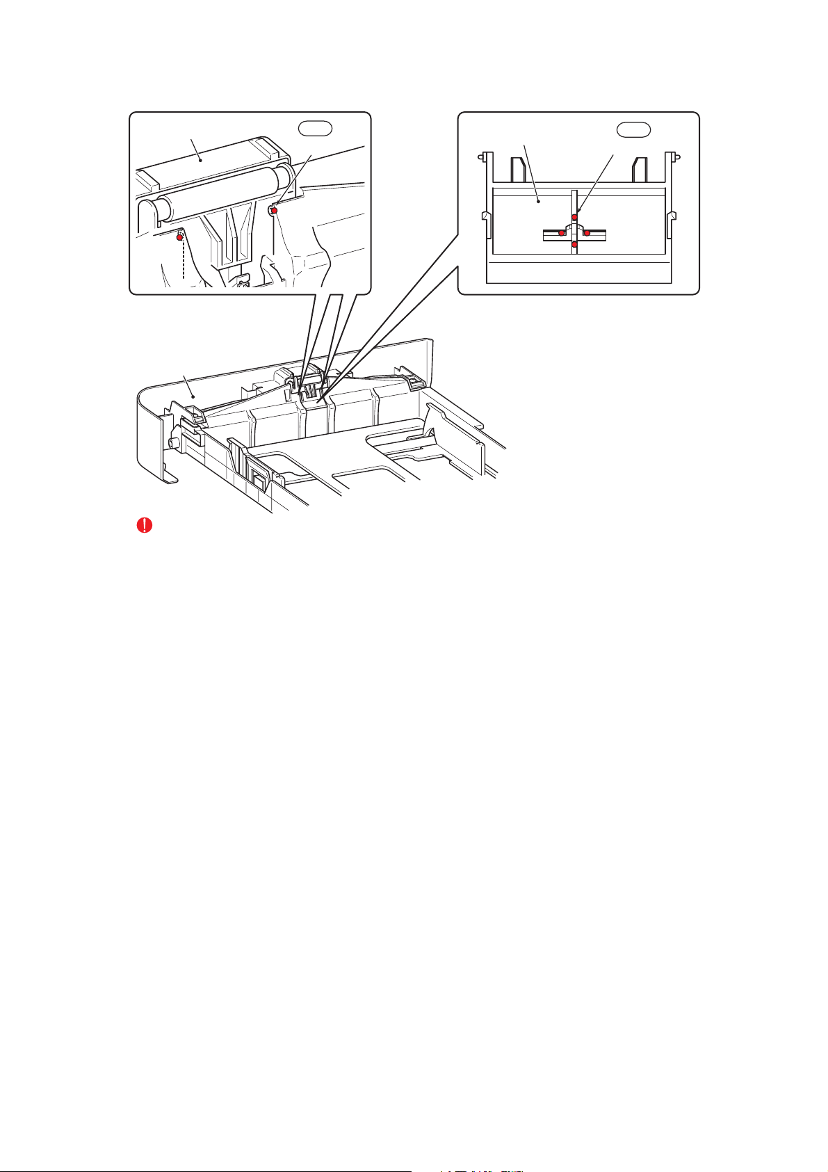
Paper tray unit
EM2
2 places
Separation pad ASSY
EM2
4 places
EM2: MOLYKOTE EM-D110
(2mm dia. ball)
Paper tray unit
EM2: MOLYKOTE EM-D110
(2mm dia. ball)
CAUTION:
Be careful not to let lubricants touch the opposite side of the Separation pad ASSY.
Fig. 3-3
3-6
Confidential
Page 85

GE2
1 places
Conductive bushing
GE2
1 places
Conductive bushing
LF roller ASSY
Ejection roller ASSY
2 places
GE2
2 places
GE2: FLOIL GE-676 (2mm dia. ball)
GE2
GE2
2 places
Drive frame ASSY
Fig. 3-4
3-7
Confidential
Page 86

5. OVERVIEW OF GEARS
EJECTOR GEAR 15/25
(LU2018001)
EJECTOR GEAR 17
(LU2016001)
FUSER GEAR 22/37
EJECTOR GEAR 26
(LU2017001)
2
2
1
1
3
3
4
4
DEV GEAR 17/18R/47R
(LU2053001)
(LU2015001)
REGISTRATION GEAR
27 PENDULUM
(LU2048001)
DEV GEAR 17/33L
(LU2054001)
REGISTRATION GEAR 19
(LU2047001)
REGISTRATION DIFFERENTIAL
GEAR ASSY
(LU2049001)
FEEDER GEAR 17/22
(LU2043001)
FEEDER GEAR 26/20
11
8
8
6
6
7
7
5
5
9
9
11
14
14
15
10
10
15
12
12
13
13
P/P GEAR 29 SECTOR
(LU2045001)
T1 GEAR 38/31 SECTOR
(LU2042001)
17
17
16
16
(LU2044001)
Fig. 3-5
CAUTION:
The part codes of gears are subject to change without notice.
( ) is part code.
3-8
Confidential
Page 87

6. HARNESS ROUTING
1 ADF motor, ADF sensor PCB ASSY to Main PCB ASSY
ADF motor
<Back Side>
ADF sensor PCB ASSY
Main PCB ASSY
Main PCB Shield plate
3-9
Confidential
Page 88

2 NCU PCB, Battery ASSY, Speaker unit ASSY to MAIN PCB ASSY
NCU PCB
Main PCB ASSY
3 Document scanner unit, Panel PCB ASSY
Battery ASSY
Speaker unit ASSY
Main PCB ASSY
Main shield cover plate
Document scanner unit
3-10
Panel PCB ASSY
Confidential
Page 89

4 FUSER UNIT
Eject sensor PCB ASSY
PS PCB unit
5 FG HARNESS
Fuser unit
Laser unit
<Back side>
Main PCB ASSY
3-11
FG harness
<Left side>
Confidential
Page 90

6 MAIN FRAME R ASSY
Cover sensor harness ASSY
7
Wireless LAN PCB ASSY (only MFC7840W) / Toner LED PCB ASSY / LVPS PCB unit / Main PCB ASSY
Toner LED PCB ASSY Fan motor 60 unit
PS PCB unit SW holder Inlet harness ASSY
Wireless LAN PCB ASSY
(only MFC7840W)
Main PCB ASSY
(Main Frame L ASSY)
<Back side>
<Right side>
Toner LED PCB ASSY
3-12
PS PCB unit
Confidential
Page 91

8
TONER LED PCB ASSY / REGISTRATION FRONT SENSOR PCB ASSY / REGISTRATION REAR SENSOR PCB ASSY
Toner LED PCB ASSY
<Front side>
<Right side>
Registration rear sensor PCB ASSY
Registration front sensor PCB ASSY
9 TONER SENSOR PCB UNIT ASSY / NEW TONER SENSOR HARNESS ASSY
<Left side>
New toner sensor
harness ASSY
Main PCB ASSY
<Front side>
Toner sensor PCB unit ASSY
3-13
Confidential
Page 92

10 HIGH-VOLTAGE PS PCB / REGISTRATION SOLENOID / T1 SOLENOID
<Left side>
<Bottom side><Bottom side>
Drive sub ASSY
<Bottom side>
Registration solenoid
High-voltage PS PCB ASSY
<Front side>
T1 solenoid
<Left side>
T1 solenoidRegistration solenoid
3-14
Confidential
Page 93

7. DISASSEMBLY FLOW
FRONT COVER
ASSY
00s/00s
ROLLER HOLDER
ASSY
00s/00s
FAN MOTOR 60
UNIT
00s/00s
COVER SENSOR
HARNESS ASSY
00s/00s
CORNER
COVER
00s/00s
SIDE CO VER R
ASSY
00s/00s
SIDE CO VER L
ASSY
00s/00s
JOINT COVER
ASSY
00s/00s
FILTER ASSY
00s/00s
MAIN SHIELD
COVER PLATE
00s/00s
INNER CHUTE
ASSY
00s/00s
FUSER UNIT
00s/00s
ADF UNIT
00s/00s
BACK COVER
00s/00s
FUSER COVER
ASSY
00s/00s
OUTER
CHUTE ASSY
00s/00s
EJECT ACTUATOR
SPRING / EJECT
ACTUATOR
00s/00s
DOCUMENT
SCANNER UNIT
00s/00s
SPEAKER /
BATTERY
00s/00s
RUBBER FOOT
00s/00s
SEPARATION PAD
ASSY / SEPARATION
PAD SPRING
00s/00s
EJECT ROLLER
ASSY 1 / BUSH
00s/00s
NCU PCB
00s/00s
TONER LED
PCB ASSY/
LED HOLDER
00s/00s
WIRELESS LAN
PCB
ASSY
00s/00s
LVPS PCB
UNIT
00s/00s
LV SHIELD
PLATE 2
00s/00s
REGISTRATION FRONT
SENSOR PCB ASSY
00s/00s
LASER UNIT
00s/00s
MAIN FRAME
L ASSY
00s/00s
REGISTRATION REAR
SENSOR PCB ASSY
00s/00s
TONER SENSOR
PCB UNIT ASSY
HIGH-VOLTAGE
PS PCB ASSY
00s/00s 00s/00s
DRIVE SUB
DEV JOINT
DEV GEAR
00s/00s
JOINT / 53R
MAIN PCB A SSY
ASSY
00s/00s
REGISTRATION
00s/00s 00s/00s
SOLENOID
T1 SOLENOID
00s/00s00s/00s
MAIN SHIELD
PLATE
00s/00s
EJECT
SENSOR PCB
00s/00s
Fig. 3-6
3-15
Confidential
Page 94

8. DISASSEMBLY PROCEDURE
■ Preparation
Prior to proceeding with the disassembly procedure,
(1) Unplug
• the AC cord,
• the modular jack of the telephone line,
• the USB cable, if connected,
• the LAN cable, if connected,
• the modular jack of the external telephone set if connected.
(2) Remove
•the Paper tray,
• the Toner cartridge and Drum unit
USB I/F cable
LAN cable
Telephone line cord
AC cord
Drum/Toner unit
Paper tray unit
Fig. 3-7
3-16
Confidential
Page 95

8.1 SEPARATION PAD ASSY
(1) Lift up the Separation pad ASSY.
(2) Release the Boss to remove the Separation pad ASSY from the Paper tray unit.
(3) Remove the Separation pad spring from the Paper tray unit.
2b
Separation pad ASSY
2a 2a
Paper tray ASSY
Separation pad spring
Boss
1
3
Paper tray ASSY
Paper tray ASSY
Fig. 3-8
3-17
Confidential
Page 96

8.2 FRONT COVER ASSY
8.2.1
FRONT COVER ASSY
(1) Open the Front cover ASSY.
(2) Release the Hook to remove the DEV joint link from the Front cover ASSY.
DEV joint link
Hook
2
Fig. 3-9
3-18
1
Front cover ASSY
Confidential
Page 97

(3) Release the Hook of the Front cover ASSY from the Front cover top.
(4) Remove the Boss of the Front chute ASSY, and then remove the Front cover ASSY from
the Main body.
Front chute ASSY
Boss
(Front chute ASSY)
Front cover top
3a
Hook
4a
3b
Boss
(Front chute ASSY)
4b
Front cover ASSY
4a
Front cover top
Front cover ASSY
Front chute ASSY
Boss
Fig. 3-10
3-19
Confidential
Page 98

8.2.2
PAPER STOPPER L / PAPER STOPPER S
(1) Release the Boss to remove the Paper stopper L from the Front cover ASSY.
(2) Release the Boss to remove the Paper stopper S from the Paper stopper L.
Paper stopper L
Paper stopper S
2a 2a
Paper stopper S
2b
Boss
1c
Paper stopper L
1a
Boss
1b 1b
Front cover ASSY
Paper stopper L
Fig. 3-11
3-20
Confidential
Page 99

8.3 BACK COVER / OUTER CHUTE ASSY
8.3.1
BACK COVER
(1) Open the Back cover.
(2) Release the Boss of the Outer chute ASSY from the Back cover.
(3) Release the Hook from the Side cover R ASSY.
(4) Slide the Back cover from the Main body, and remove it.
1
Boss
Outer chute ASSY
Boss
Side cover R ASSY
3
Boss
Hook
Boss
4
Back cover
Outer chute ASSY
2
Back cover
2
Back cover
Fig. 3-12
3-21
Confidential
Page 100

8.3.2
OUTER CHUTE ASSY
(1) Release the Boss to remove the Outer chute ASSY from the Main body.
Boss (Fuser cover ASSY)
Boss (Fuser cover ASSY)
Outer chute ASSY
1a1a
Fig. 3-13
1b
1a
Outer chute ASSY
Outer chute ASSY
3-22
Confidential
 Loading...