

Page 1

User Guide 701P36011 October 2000
Page 2

NOTICE While every care has been taken in the preparation of this guide, no liability will be
accepted by Xerox Corporation arising out of any inaccuracies or omissions.
2000 XEROX CORPORATION. All rights reserved.
©
Printed in the United States of America
XEROX
®
, XES, AccXES, The Document Company, and the identifying product names and numbers
herein are trademarks of XEROX CORPORATION.
All terms mentioned in this document that are known to be trademarks or service marks have been
appropriately capita lized; Bic Briteliner.
Prepared by:
Xerox Corporation
Global Knowledge & Langua ge Services
800 Phillips Road
Webster, New York 14580-9791
Page 3

Introduction
The introduction provides an overview of the MAX 200 and it’s
optional accessories and features. You will also find information on
how to use this guide, and the location of information you will need to
operate, maintain, and service the MAX 200.
Welcome to the MAX 200
Congratulations on acquiring your new MAX 200. Xerox Engineering
Systems looks forward to supporting you and helping you increases
your organizational prod uc tiv ity.
The MAX 200 is a high speed, highlight color production solution for
centralized operations. It is a large-format digital copier for highvolume production producing 9.2 E-size, 17 D-size, 22 C-size, 29 Bsize, and 37 A-size prints per minute, with concurrent scanning and
printing operations.
Speed and productivity
Large media supply
Image quality
Highlight color
Scan-to-file memory
Standard copy memory
Makes copies or scans at 8 IPS (200 mm/sec).
Six media supply sources – 4 x 500 feet or 600 feet rolls, 1000 cut
sheet tray for 8.5 x11 inch to 12 x 18 inch sizes, and the manual
feed tray.
Has an excellent 400-dpi-image quality for fine lines, solid areas, and
halftones with pictures, and a true photo mode for superb results.
The MAX 200 also has 256 levels of grayscale scanning. This gives
the ability to reproduce from difficult legacy documents, like
bluelines, sepias, or dark and low contrast originals.
The MAX 200 provides single pass black plus red, with no loss of
speed. The highlight feature enables editing, identifying changes,
clear date stamps, labels, watermarks, and other applications.
The MAX 200 is equipped with 160 MB of scan-to-file memory.
Additional memory can be purchased.
The MAX 200 is equipped with 208 MB of standard copy memory.
To order optional features or accessories call the Xerox Engineering
Systems sales office at 1-877-XES-8212, extension 751.
Introduction i
Page 4

Optional accessories
Some machine configurations may have optional accessories. Any
one or more accessories may or may not be installed on your
system.
The MAX 200 has the following optional accessories available:
• Folder
• Flat stacker
• Document carrier
Optional features
Some machine configurations may have optional features. Any one
or more features may or may not be installed on your system.
The MAX 200 has the following optional features available:
• Editing kit
• Stamper kit, with floppy disk drive
• Multifunction plot kit
• Multifunction scan kit
• Additional scan-to-file memory kit
To order optional accessories call Xerox Engineering Systems sales
office at 1-877-8212, extension 751.
For more information, visit the Xerox Engineering Systems web site
at http://www.xes.com.
ii Introduction
Page 5
About this guide
This user guide contains information you need to operate and
maintain the MAX 200 safely and efficiently. Please read this guide
carefully. Always refer to this user guide if a problem occurs during
the use of the MAX 200.
Conventions
Special conventions are used, in this user guide, to help you get the
most from the guide.
Typefaces and symbols in the guide identify terms and conditions.
The table below provides you with a description of the typefaces and
symbols used in this user guide.
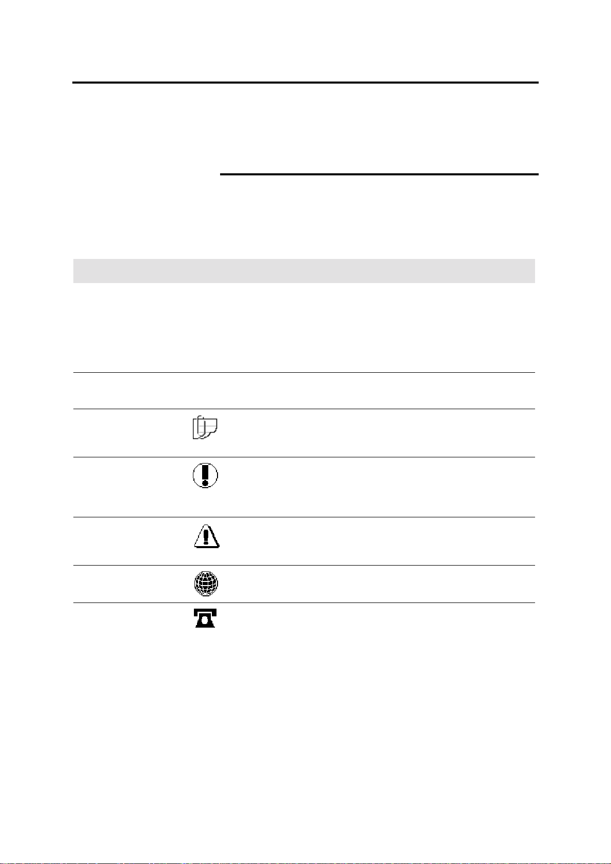
Typeface Symbol Description
Bold
Italic
Italic Note: The symbol on the left and the word note at the
Bold and
Normal
Bold WARNING: The symbol on the left and the word
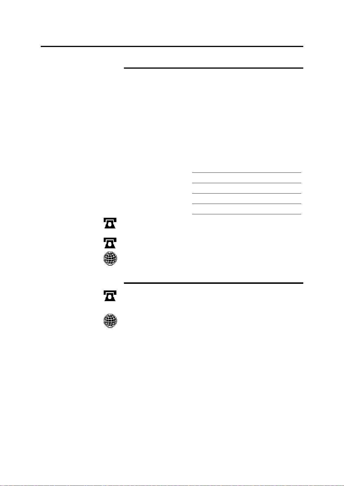
Normal This symbol identifies a web site address.
None Identifies an action to perform, like press a button or select
an area on the touch screen It also identifies terms, a
feature, an option or message.
Example 1: Select print.
Example 2: The ready to copy message is displayed.
Example 3: The normal R/E screen is displayed.
None Identifies a chapter or section title in this guide. For more
information refer to the chapter or the section title.
beginning of a sentence indicates add it ion al information,
explanations, and helpf ul su ggest ions .
Caution: The symbol on the left and the word Caution at
the beginning of a sentence alerts the user that certain
operations or procedures may cause damage to the
machine.
warning at the beginning of a sentence alerts the user to
an operation that could cause injury to them.
Normal This symbol identifies a phone number.
Introduction iii
Page 6

About this guide (continued)
Organization
The MAX 200 user guide contains fifteen chapters. Each chapter
may contain several sections. This section provides you with a brief
overview of each chapter.
For detailed information, refer to the appropriate chapter and section.
Introduction Customer support
This section of the introduction pro vid es you with the
phone numbers for service and supplies.
Compliance information
This section of the introduction provides all
necessary compliance information associated with
the MAX 200.
It’s illegal
This section of the introduction provides you
valuable information on what is illegal in your
location.
Safety notes
Getting to know the MAX 200
MAX 200 power
Media
How to make copies
This section of the introduction pro vid es you with all
safety information, warnings, and instructions
marked on the product. Failure to follow the
recommendations in this section may result in
personal injury or rescinding of the machine
operation agreement.
This chapter introduces the location and function of
the major machine components.
This chapter provides step-by-step instructions on
how to power-on and power off the machine. It also
includes ground fault protector and machine power
mode information.
This chapter provides the following media
information: specifications, storage, handling, and
usability. Step-by-step instructions on how to load
the trays is also provided.
This chapter provides step-by-step instructions on
how to make copies in auto mode, manual mode, or
from the manual feed tray.
iv Introduction
Page 7

About this guide (continued)
Organization (continued)
Basic touch screen features
Image quality touch screen features
Additional touch screen features
Finishing touch screen features
How to customize the MAX 200
Care
Problem solving
This chapter provides step-by-step instructions on
how to use the basic touch screen features.
This chapter provides step-by-step instructions on
how to use the image quality touch screen features.
This chapter provides step-by-step instructions on
how to use the additional touch screen features.
It also provides detailed information and procedures
for the editing feature.
This chapter provides step-by-step instructions on
how to use the finishing touch screen features.
It also provides detailed information and procedures
for the optional stamper feature.
This chapter provides information about the custom
presets feature and how to enter custom presets. It
also identifies, and provid es step- by-step
instructions on how to change the system, copy, and
storage disk/manager custom presets features.
This chapter provides you with information on how
to care for the MAX 200 and order supplies.
This chapter provides problem solving information.
When a machine problem occurs, go to this section
first to assist you with troubleshooting the problem.
This chapter also provides the phone number to call
for service.
Scanner interface (optional)
Plotter interface (optional)
Technical data
This chapter provides general information about the
scanner interface.
This chapter provides general information about the
plotter interface.
This chapter provides the MAX 200 technical data.
Introduction v
Page 8
Customer support
Customer account number:
Service
Should you be unable to resolve a problem, place a call to your
Xerox Engineering Systems service representative.
Your service representative will assist you in keeping your MAX 200
operating and if required, arrange for a customer service engineer to
inspect your MAX 200 and restore its perfor mance.
When you call service you will need the machine serial number. You
can access the serial number from the meter check screen. For
detailed information on how to obtain the serial number, refer to page
24.
Fill in each item below. When you call for service, they will request
this information.
Customer account name:
Machine type:
Machine serial number:
Purchase date:
United States XES
Customer First Center
Canada 1-800-939-3769.
For more information, visit the Xerox Engineering Systems web site
at http://www.xes.com.
1-877-3627 or 1-877-XES-D NCS.
Supplies
To order supplies for the MAX 200 call 1-800-538-6468. A supplies
representative will assist you with evalu ati ng your supp ly ne eds .
You can reach the 24-hour fax order line at 1-800-204-5403.
For more information, visit the Xerox Engineering Systems web site
at http://www.xes.com.
vi Introduction
Page 9

Compliance information
FCC Compliance in the USA
WARNING: This equipment has been tested and found to
comply with the limits for a Class A computing device pursuant
to Subpart B of Part 15 FCC Rules.
This equipment generates, uses, and can radiate radio frequency
energy and, if it is not installed and used in accor danc e wit h the
instruction guide, may cause interference to radio communications.
These limits are designed to provide reasonable protection against
such interference when operated in a commercial environment.
Operation of this equipment in a residential area is likely to cause
interference, in which case the user, at his own expense, will be
required to take whatever measures may be required to correct the
interference.
EME Compliance in Canada
This digital apparatus does not exceed the Class A limits for radio
noise emissions from digital apparatus set out in the radio
interference regulations of the Canadian Department of
Communications.
Conformité EEM
Cet appareil numérique est conforme aux limites d'émission de bruits
radioélectriques pour les appareils de classe A stipulées dans le
Règlement sur le brouillage radioélectrique du Ministère des
Communications du Canada.
Introduction vii
Page 10

It’s illegal
In the USA
It is against U.S. law to reproduce copyrighted material without the
permission of the copyright owner unless the copying falls within the
"Fair Use" library reproduction rights of the copyright law.
Further information on these U.S. provisions may be obtained from
the Copyright Office, Library of Congress, Washington, D.C. 20550,
or telephone the Copyright Office at (202) 707-9100 and ask for
circular 21. Copying other items may be prohibited. If you have any
questions seek legal advice.
In Canada
Parliament, by statute, has forbidden the copying of the following
subjects under certain circumstances. Penalties of fines or
imprisonment may be imposed on those guilty of making such
copies.
1. Current bank notes or current money.
2. Obligations or securities of a government or bank.
3. Exchequer bill paper or revenue paper.
4. The public seal of Canada or of a province, or the seal of a public
body or authority in Canada, or of a court of law.
5. Proclamations, orders, regulations or appointments, or notices
thereof (with intent to falsely cause same to purport to have been
printed by the Queen’s Printer for Canada, or the equivalent
printer for a province).
6. Marks, brands, seals, wrappers, or designs used by or on behalf
of the Government of Canada or of a province, the government
of a state other than Canada, or a department, board,
commission or agency established by the Government of
Canada, or a province or a government of a state other than
Canada.
7. Impressed or adhesive stamps used for the purpose of revenue
by the Government of Canada or a province or the government
of a state other than Canada.
8. Documents, registers, or records kept by public officials charged
with the duty of making or issuing certified copies thereof, where
the copy falsely purports to be a certified copy thereof.
9. Copyright material or trademarks of any manner or kind without
the consent of the copyright or trademark owner.
10. The above list is provided for your convenience and assistance,
but is not all-inclusive, and no liability is assumed for its
completeness or accuracy. In case of doubt, consult your
solicitor.
viii Introduction
Page 11

Safety notes
Your system has been designed and tested to meet strict safety
requirements. These include safety agency examination and
approval plus compliance with established environmental standards.
WARNING: Failure to follow the recommendations in this
section may result in personal injury or rescinding of the
machine operation agreement.
Maintenance safety
1. Follow all warnings and instructions marked on or supplied with
the product.
2. Unplug the units from the wall outlet before cleaning the exterior.
Always use materials specifically designated for the MAX 200.
Use of other materials may result in poor performance and could
create a hazardous situation.
3. Do not use aerosol cleaners. Follow the instructions in this
operator guide for the correct cleaning methods.
4. Never use supplies or cleaning materials for purposes other than
what they were intended. Keep all supplies and materials out of
the reach of children.
5. Do not use the units near water, wet locations, or outdoors.
6. The components of this product are equipped with a three-wire,
grounding-type plug (i.e., a plug having a grounding pin). This
plug will only fit into a grounding-type power outlet. This is a
safety feature. To avoid the risk of electric shock, contact your
electrician to replace the receptacle if you are unable to insert the
plug into the outlet.
7. Never use a ground adapter plug to connect the system to a
power source that lacks a ground connection terminal.
8. This system should be operated from the type of power source
indicated on the marking label. If you are not sure of the type of
power available, consult your local power company.
9. The power supply cord is the disconnect device for this
equipment. Make sure that the installation is near the socket
outlet and is easily accessible.
10. Do not allow anything to rest on the power cord. Do not locate
the units where someone will step on the cord.
11. The units should not be placed in a built-in installation unless
correct ventilation is provided.
Introduction ix
Page 12

Safety notes (continued)
Maintenance safety (continued)
12. Never push objects of any kind into the slots of the units as they
may touch dangerous voltage points or short out parts that could
result in a risk of fire or electric shock.
13. Never spill liquid of any kind on the units.
14. Never remove any covers or guards that require a tool for
removal. There are no operator serviceable areas within these
covers.
15. Never attempt any maintenance function that is not specified in
this operator guide.
16. Never defeat interlock switches. Machines are designed to
prevent operator access to unsafe areas. Covers, guards, and
interlock switches are provided to ensure that the system will not
operate with the covers opened.
17. If the power plug is used as a disconnect device, instructions
shall comply with UL 1950 Sec. 1.7.2. The power switch does
not break power to the low voltage power supply.
18. Unplug the reprographic system from the wall outlet and call for
service under the following conditions:
• When the power cord is damaged or frayed.
• If the gas piston springs in the upper cover of the printer lose
their strength.
• If liquid has been spilled into the product.
• If the units have been exposed to rain or water.
• If the units are producing unusual noises or odors.
• If the units or the cabinets have been damaged.
19. If you need additional safety information concerning the MAX 200
or XES supply materials, call:
United States
Xerox Hotline
In other countries Please call your local Xerox Engineering
1-800-828-6571.
Systems service representative for help.
Ozone safety
This product produces ozone during normal operation. The ozone
produced is heavier than the air and quantity is dependent on the
copy volume. Providing the proper environmental parameter, as
specified in Xerox Engine erin g S ystem installation procedures , wil l
ensure that concentration levels meet safe limits.
If additional information concerning ozone is needed, request the
Xerox publication Ozone, 600P83222. Please call your Xerox
Engineering System s repres entat iv e.
x Introduction
Page 13

Table of contents
Introduction..........................................................................................................................i
Welcome to the MAX 200 .....................................................................................................................i
Optional accessories............................................................................................................................ii
Optional features..................................................................................................................................ii
About this guide ..................................................................................................................................iii
Conventions .................................................................................................................................... iii
Organization....................................................................................................................................iv
Customer support ...............................................................................................................................vi
Service ............................................................................................................................................vi
Supplies...........................................................................................................................................vi
Compliance information ..................................................................................................................... vii
FCC Compliance in the USA.......................................................................................................... vii
EME Compliance in Canada..........................................................................................................vii
Conformité EEM.............................................................................................................................vii
It’s illegal ........................................................................................................................................... viii
In the USA..................................................................................................................................... viii
In Canada...................................................................................................................................... viii
Safety notes........................................................................................................................................ix
Maintenance safety .........................................................................................................................ix
Ozone safety ....................................................................................................................................x
Getting to know the MAX 200...........................................................................................15
Scanner..............................................................................................................................................15
Front...............................................................................................................................................15
Rear................................................................................................................................................16
Printer.................................................................................................................................................17
Manual feed tray.............................................................................................................................18
Touch screen .....................................................................................................................................19
Components...................................................................................................................................19
How do I know if a feature or option is available?..........................................................................20
Scanner control panel........................................................................................................................21
Upper components.........................................................................................................................21
Lower components.........................................................................................................................22
Information button ..........................................................................................................................23
Stored jobs button ..........................................................................................................................23
Meter check button.........................................................................................................................24
Custom presets button...................................................................................................................24
Review button.................................................................................................................................25
Stop document button ....................................................................................................................25
Clear button....................................................................................................................................26
Clear all button...............................................................................................................................26
Check/repair button........................................................................................................................26
Stop copy button ............................................................................................................................27
Interrupt button...............................................................................................................................27
Power save button..........................................................................................................................28
Scanner document feed panel...........................................................................................................28
Auto mode panel................................................................................................................................29
Printer control panel...........................................................................................................................30
Messages.......................................................................................................................................30
Printer diagram...............................................................................................................................32
Top indicator lamps........................................................................................................................33
Buttons ...........................................................................................................................................33
Manual feed panel .............................................................................................................................34
RFC panel..........................................................................................................................................36
Cut sheet panel..................................................................................................................................37
Media type and series panel..............................................................................................................38
Media series panel (tray 5) ................................................................................................................38
MAX 200 power..................................................................................................................39
Switching the power-on......................................................................................................................39
Table of contents xi
Page 14

Switching the power off......................................................................................................................40
Ground fault protectors ......................................................................................................................41
Printer ground fault.........................................................................................................................41
Scanner ground fault......................................................................................................................41
Warm-up ............................................................................................................................................42
Auto power-off mode..........................................................................................................................42
Power save ........................................................................................................................................42
Media..................................................................................................................................43
How to handle unusable documents..................................................................................................43
Torn or ripped document................................................................................................................43
Document with staples ...................................................................................................................43
Document with curl.........................................................................................................................43
Bent document ...............................................................................................................................43
Transparent document ...................................................................................................................43
How to store cut sheet media ............................................................................................................44
How to store roll media ......................................................................................................................44
Media type and weight charts ............................................................................................................45
Media size charts...............................................................................................................................46
Maximum scan length........................................................................................................................47
Maximum print length.........................................................................................................................47
How do I know when tray 5 or a drawer is empty?............................................................................48
From the auto mode panel .............................................................................................................48
From the R/E, media, cut touch screen..........................................................................................48
From the RFC panel.......................................................................................................................48
From the cut sheet panel ...............................................................................................................48
How to load roll media .......................................................................................................................49
How to load cut sheet media .............................................................................................................51
How to cut roll media .........................................................................................................................52
Auto cut ..........................................................................................................................................52
Manual cut......................................................................................................................................53
Heater ................................................................................................................................................54
Humidifier (optional)...........................................................................................................................55
How to make copies..........................................................................................................56
Before making copies ........................................................................................................................56
In auto mode......................................................................................................................................57
In manual mode .................................................................................................................................60
With the manual feed tray..............................................................................................................64
Basic touch screen features.............................................................................................68
Media cut mode .................................................................................................................................69
R/E; media; cut ..................................................................................................................................70
Normal R/E.....................................................................................................................................71
R/E by L&W....................................................................................................................................73
Normal R/E calculator ....................................................................................................................75
Paper length adjustment................................................................................................................79
Image density.....................................................................................................................................87
Document image type........................................................................................................................88
Print color...........................................................................................................................................90
One color (black or red) .................................................................................................................90
Two color (black and red)...............................................................................................................91
Image quality touch screen features................................................................................92
Sharpness..........................................................................................................................................93
Scan color sensitivity .........................................................................................................................94
Additional to u c h screen featur e s.....................................................................................95
Image location....................................................................................................................................96
Editing................................................................................................................................................97
Overall editing ................................................................................................................................98
Marker editing...............................................................................................................................107
Coordinates editing ......................................................................................................................119
Finishing tou c h screen feature s....................................................................................129
E-sorter ............................................................................................................................................130
Off (uncollated).............................................................................................................................131
Collated ........................................................................................................................................132
xii Table of contents
Page 15

Program........................................................................................................................................135
Stamper ...........................................................................................................................................137
Stamp pattern...............................................................................................................................139
Numbering....................................................................................................................................141
Stamp location..............................................................................................................................147
Date stamp...................................................................................................................................153
Stamp color ..................................................................................................................................158
Folder...............................................................................................................................................159
Paper exit (for machines with no folder)..........................................................................................161
Stored jobs......................................................................................................................162
How to store, recall or delete a job..................................................................................................162
Store jobs log...................................................................................................................................164
Job feature log .................................................................................................................................165
How to customize the MAX 200......................................................................................167
Identifying the system features........................................................................................................168
Identifying the copy features............................................................................................................170
Identifying the storage/disk manager features.................................................................................173
How to enter custom presets ...........................................................................................................174
How to change the system features ................................................................................................176
Time & date..................................................................................................................................176
Auto power off ..............................................................................................................................177
Auto power save...........................................................................................................................178
Auto clear/backlight off.................................................................................................................179
Document width............................................................................................................................181
Attention tone ...............................................................................................................................182
Plotter setup .................................................................................................................................183
Loading stamp data......................................................................................................................190
Additional setting..........................................................................................................................192
How to change the copy features....................................................................................................194
Reduce/enlarge presets ...............................................................................................................194
Media type and width for auto mode............................................................................................196
Stamp location and orientation.....................................................................................................198
Date stamp format........................................................................................................................201
Folder setup .................................................................................................................................203
Auto/manual mode .......................................................................................................................212
Media cut mode and document orientation..................................................................................214
Lead/trail edge default for synchronized......................................................................................216
Variable length default..................................................................................................................218
Background suppression level default .........................................................................................220
Image density...............................................................................................................................223
Document image type ..................................................................................................................224
Scan to print color default ............................................................................................................225
Color recognition range................................................................................................................226
Marker area recognition ...............................................................................................................229
Additional setting..........................................................................................................................231
How to change the storage/disk manager features.........................................................................233
Stamp creation/deletion ...............................................................................................................233
Disk manager (format/duplication) ...............................................................................................245
E-sorter (program) settings ..........................................................................................................249
Care..................................................................................................................................256
Cleaning the scanner platen glass...................................................................................................256
Ordering supplies.............................................................................................................................256
Problem solving..............................................................................................................257
Problem solving chart ......................................................................................................................257
Clearing a scanner jam....................................................................................................................259
Clearing a printer jam.......................................................................................................................260
Indicator lamps 1 - 4.....................................................................................................................261
Indicator lamp 5............................................................................................................................262
Indicator lamps 6 or 7...................................................................................................................263
Indicator lamp 8............................................................................................................................264
Indicator lamp 9............................................................................................................................266
Indicator lamp 10..........................................................................................................................268
Indicator lamp 11 or 12.................................................................................................................270
Table of contents xiii
Page 16

Replacing the toner cartridge...........................................................................................................271
Relatch the fuser..............................................................................................................................273
Calling for service ............................................................................................................................274
Scanner interface (optional)...........................................................................................275
Overview..........................................................................................................................................275
Plotter interfa c e (optional)..............................................................................................276
Overview..........................................................................................................................................276
How to enter copy mode from plot mode.....................................................................................277
Technical data.................................................................................................................278
Printer specifications........................................................................................................................278
Physical characteristics................................................................................................................278
Floor space requirements ............................................................................................................278
Scanner specifications.....................................................................................................................279
Physical characteristics................................................................................................................279
Floor space requirements ............................................................................................................279
System requirements.......................................................................................................................279
Electrical...........................................................................................................................................280
Environmental data..........................................................................................................................280
Media specifications.........................................................................................................................281
System capability.............................................................................................................................281
Material safety data sheet (MSDS) information...............................................................................282
xiv Table of contents
Page 17
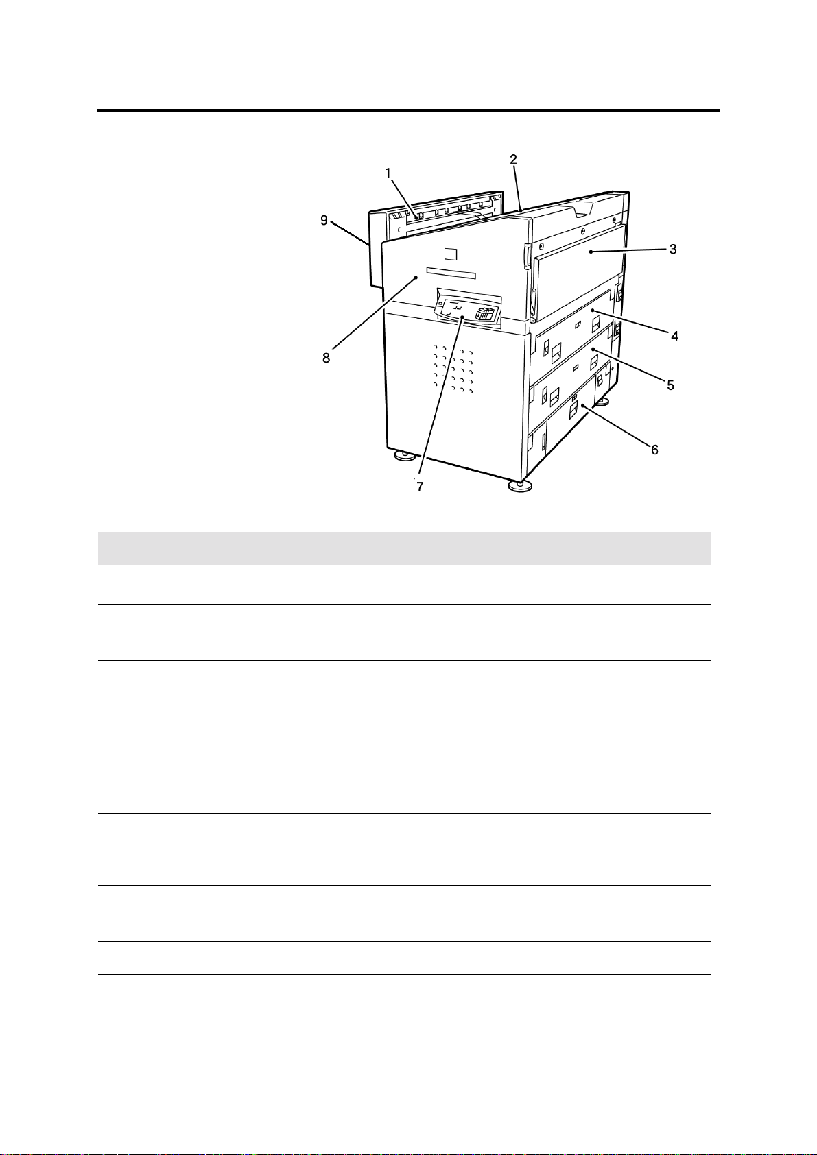
Getting to know the MAX 200
Scanner
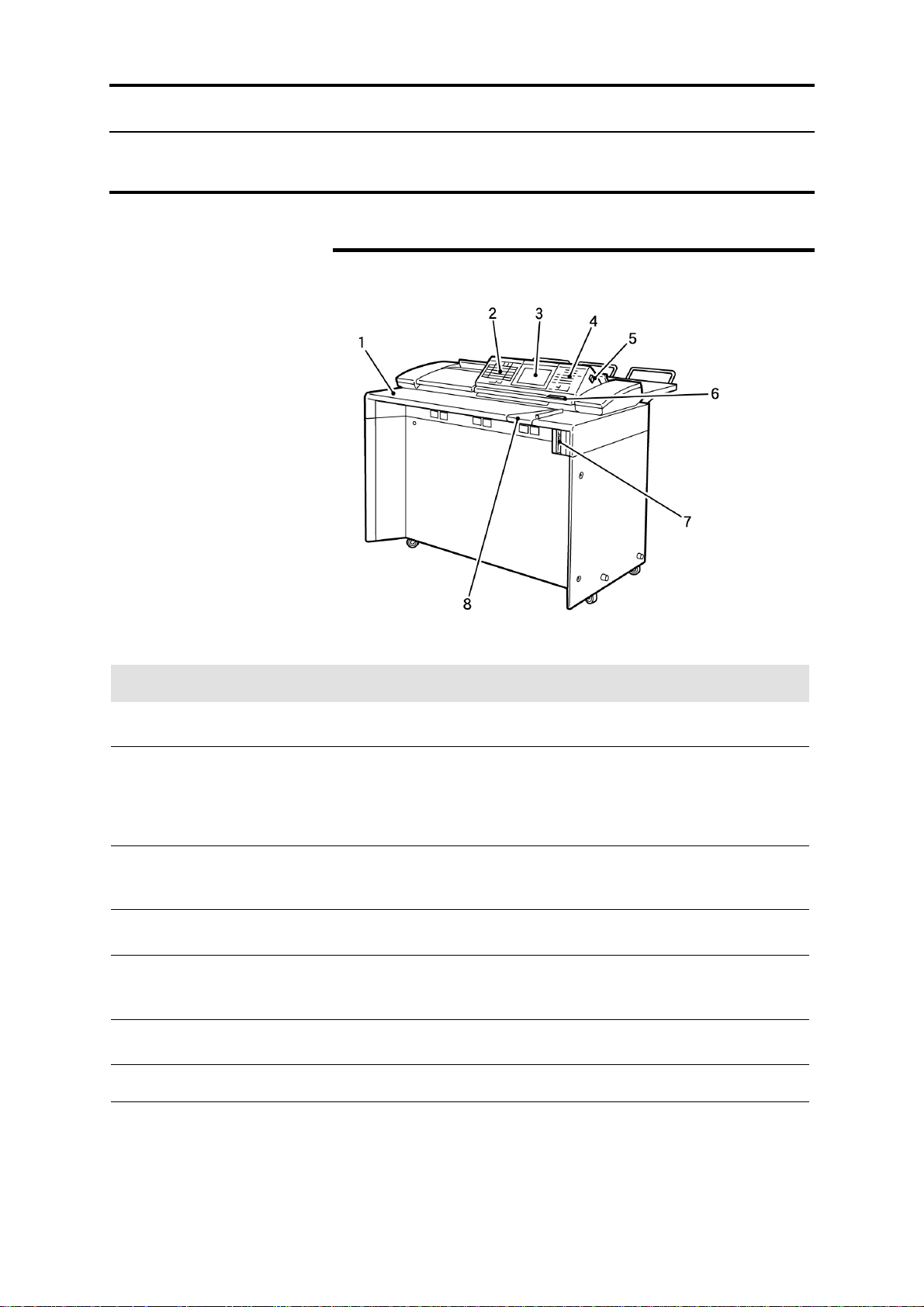
Front
No. Name Function
1 Document shelf
2 Auto mode panel
3 Touch screen
4 Scanner control panel
5 Power switch
6 Document feed direction
panel
7 Floppy diskette drive
8 Document guide
Place documents face down on the document shelf and feed into the
scanner.
The auto mode panel is used to select the media size, document
feed direction, and mode of operation. When in auto mode the panel
also displays the document size, media type, and media supply
information. For detailed information about the panel, refer to page
29.
Displays available features and options, messages, and job
information. For detailed information about the touch screens, refer
to page 19.
Contains the numeric keypad, control buttons and the document
counter. For detailed information about the panel, refer to page 21.
Switches the scanner power-on or off. If your system is equipped
with the printer and the scanner switch is positioned to off, power to
the printer is also removed.
Displays the document feed direction.
The floppy disk drive is used to store stamp data.
The document guide registers the document during the scan
process.
Getting to know the MAX 200 15
Page 18
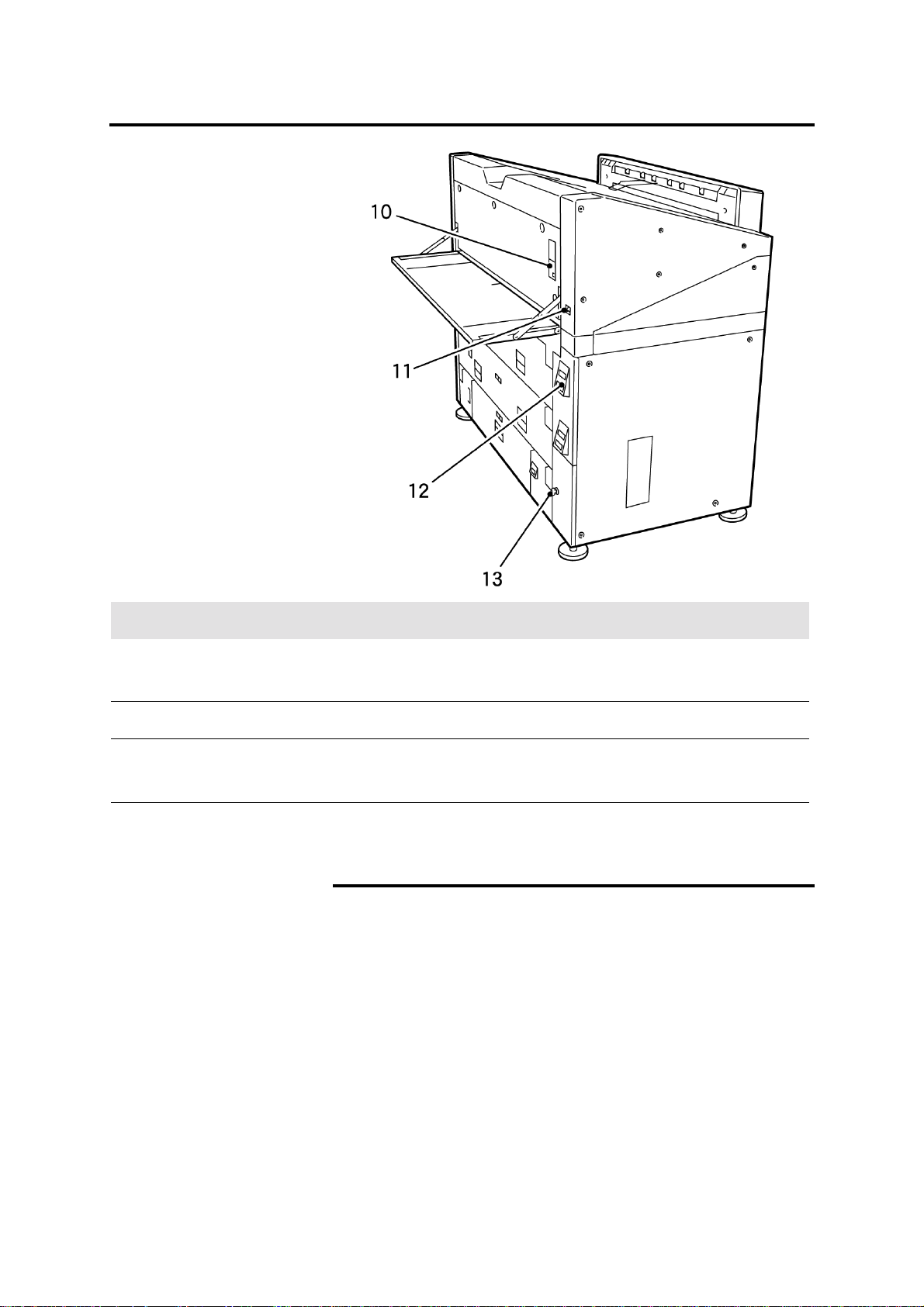
Scanner (continued)
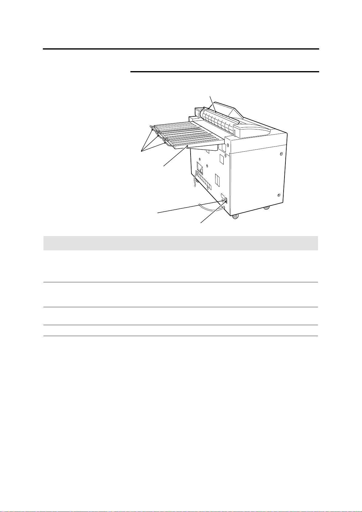
Rear
10
9
11
12
No. Name Function
9 Document exit guide
10 Document support
guides
11 Document output tray
12 Scanner circuit breaker
13 Ground fault protector
The document exit guide is positioned manually. If the guide is
positioned up, documents are fed to the document output tray. If the
guide is positioned down, documents are fed to the front of the
scanner.
If documents are longer than 36 inches, pull out the document
support guides. The guide keeps long documents from falling off the
document output tray.
The document output tray receives documents when the document
exit guide is in the up position.
The circuit breaker switches the main power to the scanner on or off.
If the scanner detects an electrical problem, the ground fault
protector switches the scanner power off.
13
16 Getting to know the MAX 200
Page 19
Printer
Right side
No. Name Function
1 Copy output tray exit
area
2 Copy output tray
3 Manual feed tray
4 RFC drawer 1
5 RFC drawer 2
6 Cut sheet tray
7 Printer control panel
Copies that exit this area are feed to the copy output tray.
Copies are placed onto the copy output tray when there is no
folder or stacker. Maximum media tray capacity is 100 sheets
(20 –24 lb.).
Supplies standard or nonstandard media sizes. All media is feed
manually.
The roll feed cutter (RFC drawer 1) supplies up to 2 rolls of media.
The media type and series panel is included in the drawer, for
detailed information about the panel, refer to page 38.
The roll feed cutter (RFC drawer 2) supplies up to 2 rolls of media.
The media type and series panel is included in the drawer, for
detailed information about the panel, refer to page 38.
Supplies 1000 sheets of cut sheet media, 8.5 x 11 inch to 12 x 18
inch. The cut sheet tray is also referred to as tray 5. The media
series panel is included in the tray, for detail information about the
panel, refer to page 38.
Displays the printer status and includes the offline button, and the
red and black increase toner buttons. For detailed information
about the panel, refer to page 30.
Front
8 Front door
9 Copy output
folder/stacker exit area
Getting to know the MAX 200 17
Open to access media jams or to replace the toner cartridge.
Copies that exit this area and are fed into the folder or stacker.
Page 20
Printer (continued)
Right side
No. Name Function
10 Manual feed panel
11 Power switch
12 RFC panel
13 Lower door
Displays the manual feed tray status and contains the manual feed
control buttons. For detailed information about the panel, refer to
page 34.
Switches the printer power-on or off.
Displays media roll information. The trim button controls the auto
cut function. For detailed information about the panel, refer to page
36.
Open to access the printer circuit breaker, heater switch and the
humidifier switch (optional).
Manual feed tray
Using the manual feed tray is useful when the correct size or type
of media is not loaded in the printer, or when you need to make a
copy on special size media (A – E).
For detailed information on how to make copies, with the manual
feed tray, refer to page 70.
Back
18 Getting to know the MAX 200
Page 21
Touch screen
y
The touch screens contain messages, copy quantity information,
tabs, buttons, icons and text. There are two types of screens, the
copy feature screens and the custom presets screens.
The copy feature screens are grouped into four feature group tabs;
basic, image quality, additional, and finishing. Whenever a selection
is made from any of the tabs, the selection overrides the custom
presets values until the clear all button is pressed.
The custom presets screens are grouped into three feature group
tabs; system, copy, and storage/disk manager. When you enter
custom presets you can customize the MAX 200 defaults, to meet
your workflow requirements .
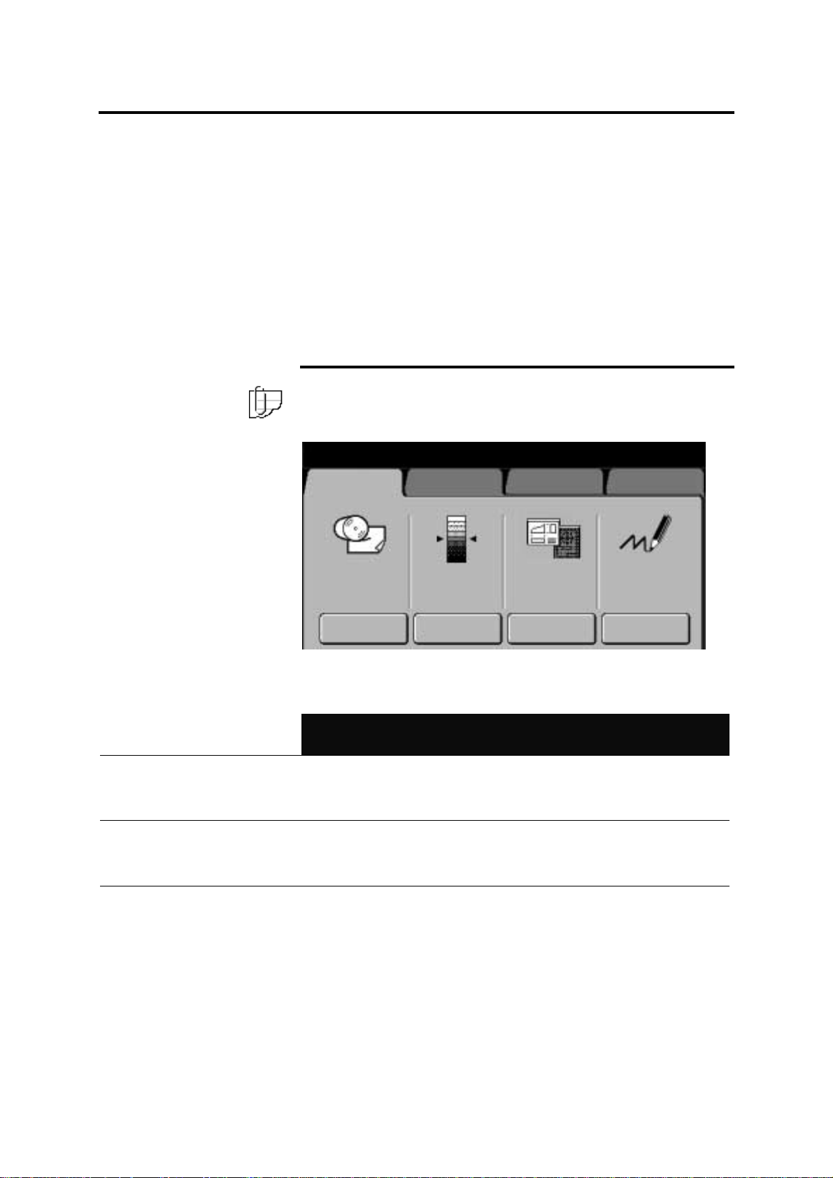
Components
Note: The screen below is an example of a copy feature screen.
The text above the selection buttons, displays the current copy
feature selections.
Ready to cop
Load documents face down
Basic
Image Quality
Additional
Selected 01
Finishing
Message bar
Tabs
Icons and text
Selection buttons
Auto-Mode
R / E; Media:
Cut
Black Red Line
Image
Density
Fixed
Document
Image Type
Black Only
Print Color
Displays the machine conditions, operator instructions, and copy
quantity. In this example the message bar displays the following
information:
Ready to copy Selected 01
Load documents face down
There are four feature group tabs (basic, image quality, additional,
finishing). When a tab is selected, the feature group menu is
displayed. Each feature group has a specific set of selections.
Each feature group screen is divided into columns, each column may
contain an icon with text. Each column provides the operator a quick
overview of the current job selections.
To select touch screen features or options, touch the desired button.
Getting to know the MAX 200 19
Page 22
Touch screen (continued)
y
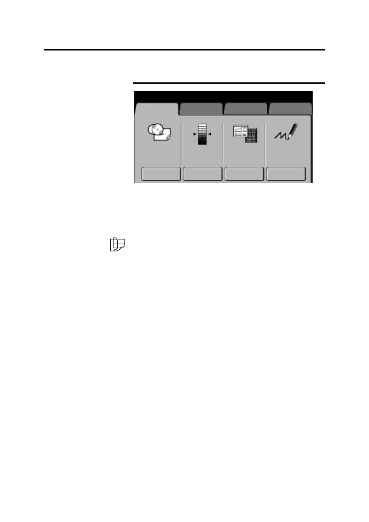
How do I know if a feature or option is available?
Ready to cop
Load documents face down
Basic
Auto-Mode
R / E; Media:
Cut
Image Quality
Black Red
Image
Density
Additional
Line
Fixed
Document
Image Type
Selected 01
Finishing
Black Only
Print Color
An available feature or option is shown raised and is not grayed out.
In this example the basic feature group tab is available, along with
the four selection buttons.
Any tab or button that is not raised and appears to be grayed out is
not available. In this example the following tabs are not available:
image quality, addit ion al, an d finis h ing.
Note: Any feature group tab or selection button that is not available,
may have a conflict with a current selection. Sometimes a specific
option must be selected first, or your machine is not equipped with
the optional accessory.
20 Getting to know the MAX 200
Page 23
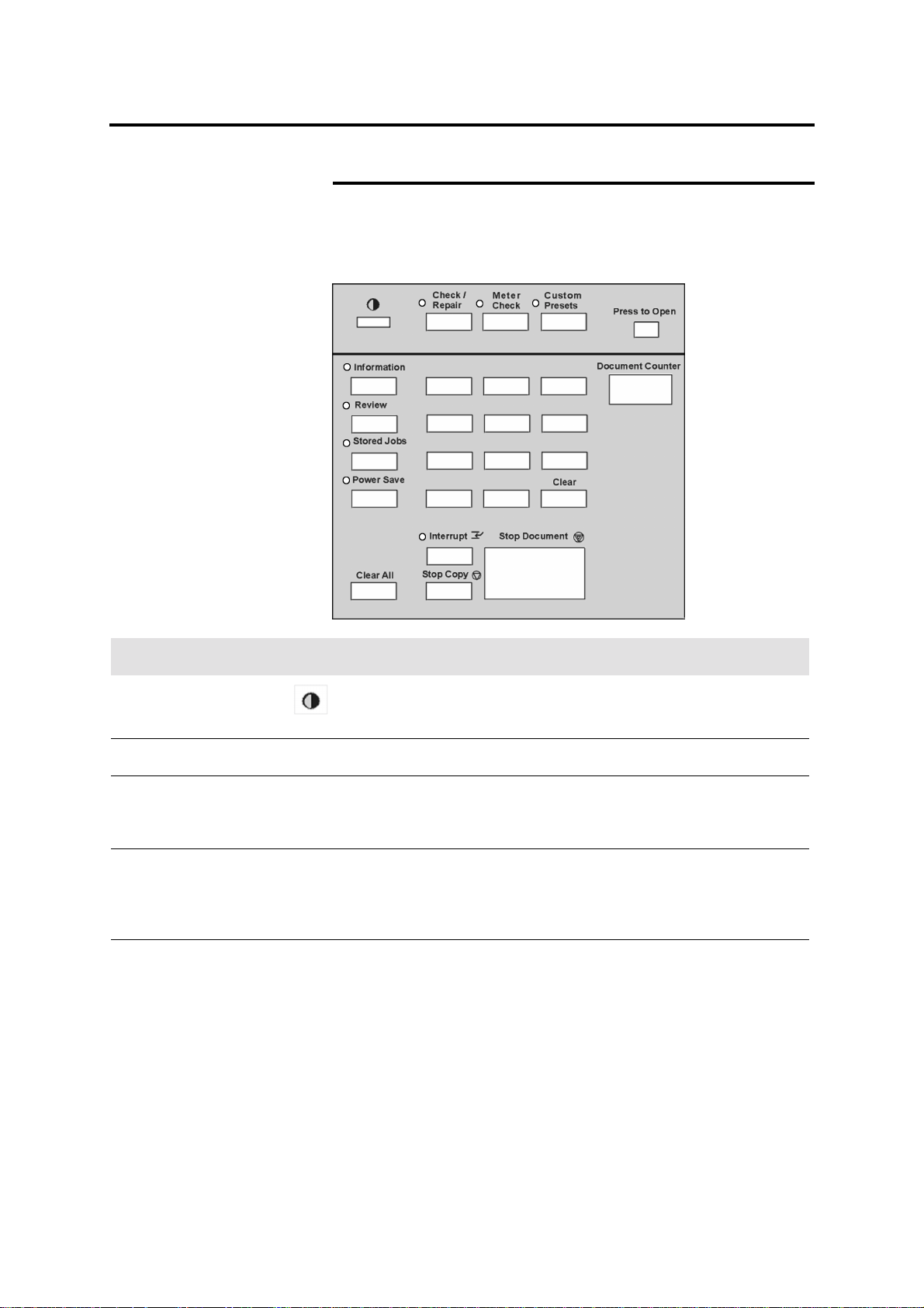
Scanner control panel
Upper components
The scanner control panel is divided into two sections; the upper
and lower sections. The upper section is located under the scanner
control panel cover. To access the upper section, press the press to
open latch and release.
123
4
7
.
56
98
0C
Name Function
Brightness control dial The brightness control dial adjusts the brightness of the touch
screen.
Check/repair button The check/repair button is for the service representative.
Meter check button The meter check button provides access to the billing meter. The
meter reads the printer usage. For detailed information on how to
use the meter check button, refer to page 24.
Custom presets button The custom presets button provides access to the system, copy,
and storage/disk manager defaults. You can change the defaults to
meet your specific needs. For detailed information about the custom
presets button, refer to page 24.
Press to open latch Press and release the press to open latch, to open the top cover of
the scanner control panel.
Getting to know the MAX 200 21
Page 24
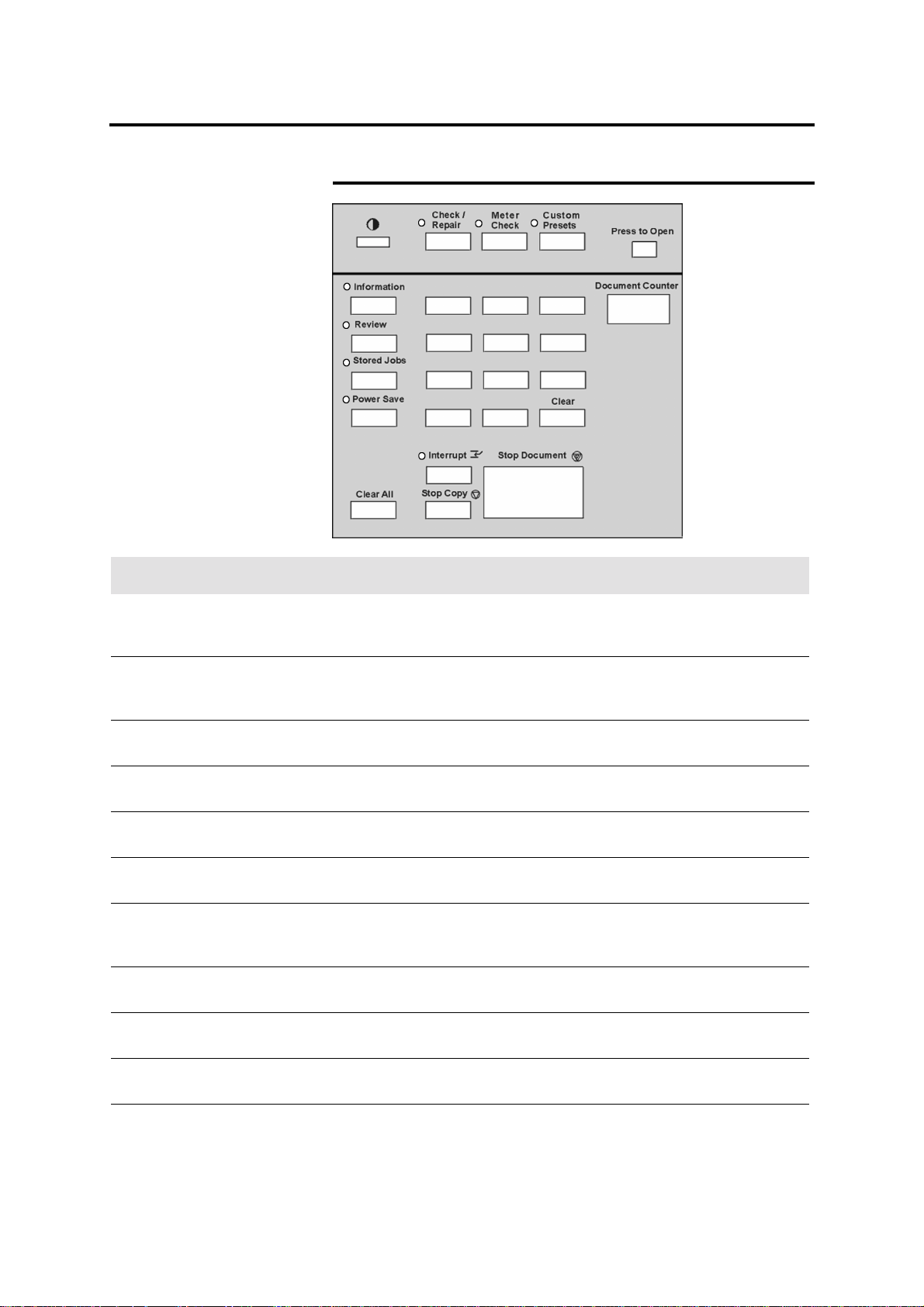
Scanner control panel (continued)
Lower components
123
4
7
.
56
98
0C
Name Function
Information button Press the information button, to provided online information about
the machine feature and options. For detailed information, refer to
page 23.
Review button Press the review button, to display the current job feature settings,
and move quickly between screens. For detailed information, refer
to page 25.
Stored jobs button Press the stored jobs button to store, recall or delete a stored job.
For detailed information, refer to page 162.
Power save button Press the power save button, to enter or exit the power saver
mode. For detailed information, refer to page 28.
Document counter The document counter displays the total number of scanned
documents. To reset, press the button beside the counter.
Clear button Press the clear (C) button, to clear numeric data. For detailed
information, refer to page 26.
Clear all button Press the clear all button, to clear current copy feature selections
and numeric data. The machine automatically returns to the custom
presets default settings. For detailed information, refer to page 26.
Interrupt button Press the interrupt button to suspend the current job, so a different
job can be run. For detailed information, refer to page 27.
Stop copy button Press the stop copy button to stop the print cycle. For detailed
information, refer to page 27.
Stop document button Press the stop document button to stop the scan operation. For
detailed information, refer to page 25.
Numeric keypad Press the keypad buttons to enter quantity and other information.
22 Getting to know the MAX 200
Page 25
Scanner control panel (continued)
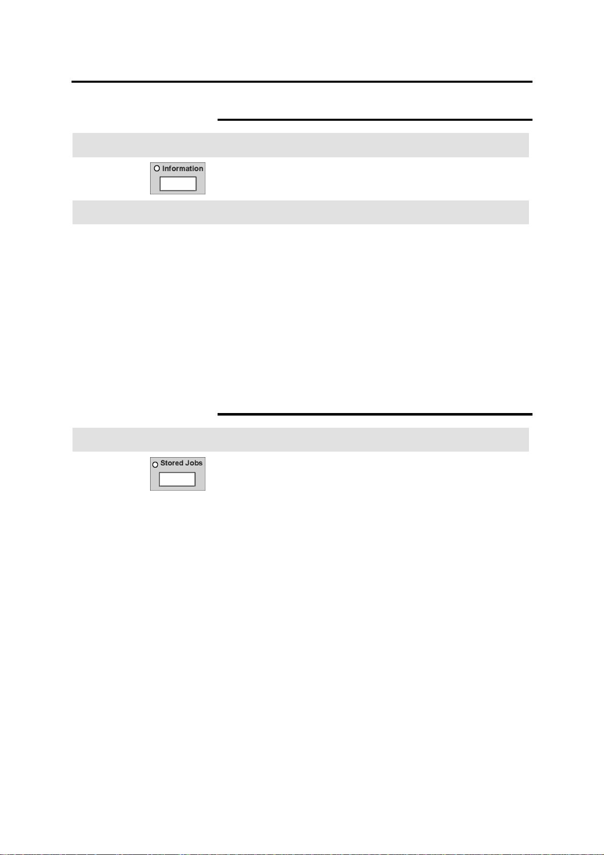
Information button
Introduction
The information button is a quick way to access online information.
For additional information, refer to the user guide.
Procedure
1. Press the information button.
The information indicator lamp is lit and the information main-
menu screen is displa yed.
2. Select the desired topic.
Information about the topic is displayed or a sub topic menu is
displayed.
Select close to return to the previous screen.
3. To exit, press the information button.
The basic feature group screen is displayed and the
information indicator lamp is not lit.
Introduction
Stored jobs button
This stored jobs button allows you to store (create), recall, or
delete stored jobs. For detailed information refer to page 162.
Getting to know the MAX 200 23
Page 26
Scanner control panel (continued)
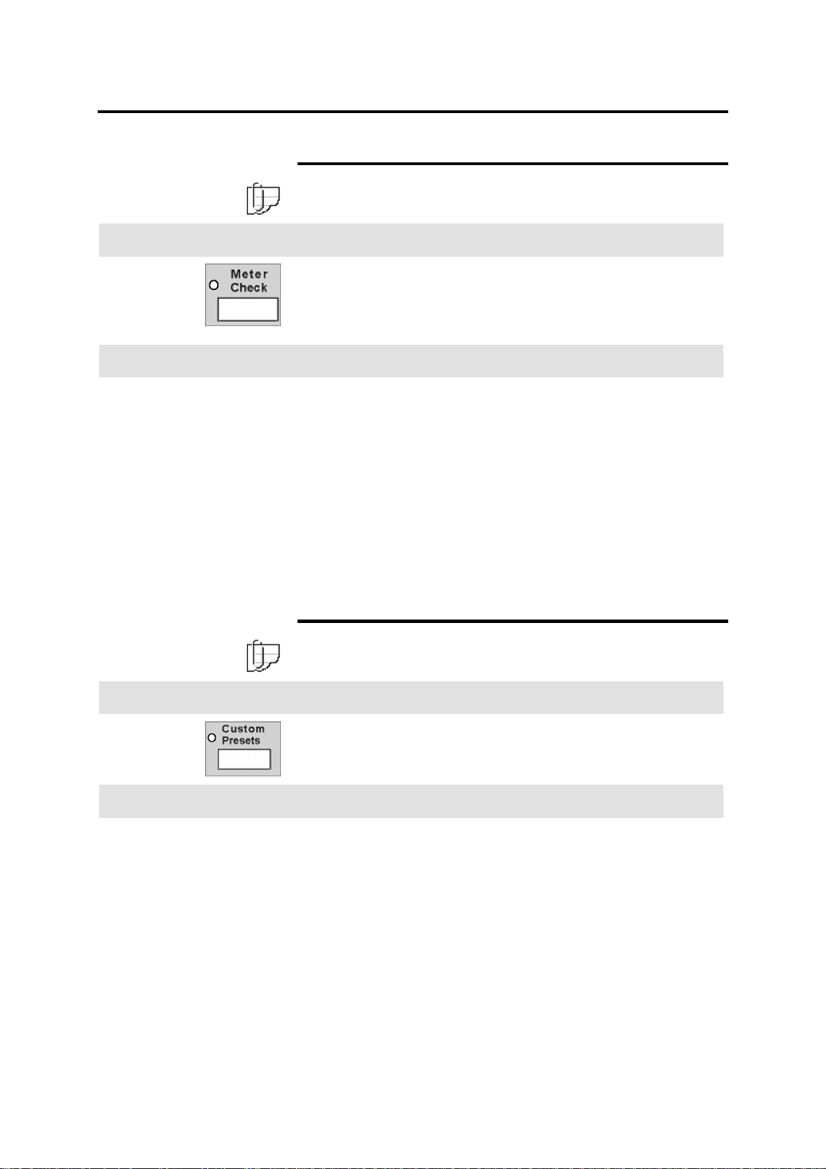
Meter check button
Note: The meter check screen displays two fields, billing and
service. The service field is for the service representative.
Introduction
The meter check button provides access to the billing meter. The
meter displays the printer media usage.
The machine serial number is also displayed on the meter check
screen. It is located at the lower right corner of the screen.
Procedure
1. Press the press to open latch, at the upper right corner of the
scanner control panel cover.
The scanner control panel cover is open.
2. Press the meter check button.
The meter check indicator lamp is lit and the meter check screen
is displayed.
Introduction
Procedure
The billing field displays the media usage.
3. To exit, press the meter check button.
The basic feature group screen is displayed.
Custom presets button
Note: For detailed information on how to enter the custom presets
feature, refer to page 174.
The custom presets button provides access to various default
settings. There are three feature groups; system, copy and
storage/disk manager.
1. Press the press to open latch, at the upper right corner of the
scanner control panel cover.
The scanner control panel cover is open.
2. Ensure the machine is in copy mode. If needed, refer to page
277.
3. Press the custom presets button.
The custom presets indicator lamp is lit and the system features
tab is displayed.
4. Select the desired feature tab.
5. To exit, press the custom presets button.
24 Getting to know the MAX 200
Page 27
Scanner control panel (continued)
Review bu tton
Introduction
The review button provides quick access to review the current job
features and quickly move between screens to make changes.
Before printing your job, you may want to review all the selected
features.
Procedure
1. Press the review button.
• The review indicator lamp is lit and the review screen is
displayed. The first column of text, next to the feature
button, is the name of the copy feature.
• The second column of text, displays the selected feature
option.
2. To make changes, select the desired copy feature button.
The copy feature screen is displayed.
Introduction
3. Enter your changes.
4. Perform one of the following:
a. If you do not have any more changes, select done on the
copy feature screen. Continue to the next step.
b. If you need to make more feature changes press the review
button again. The review screen is displayed and any
feature button that is highlighted indicates a change has
been made.
When all your changes are complete select done on the on
the copy feature screen or select close on the review
screen to save your changes. Continue to the next step.
5. Select the copy quantity.
6. Insert your document into the scanner.
Stop document button
Press the stop document button to stop the scan process. If a
document begins to tear or skew, always press the stop document
button immediately. Stopping the document may save your
document and eliminate possible document jams.
Note: If a document jam does occurs, refer to page 259.
Getting to know the MAX 200 25
Page 28
Scanner control panel (continued)
Clear button
Introduction
When the clear (C) button is pressed, the machine clears the
C
Introduction
numeric data entered from the keypad.
Clear all button
When the clear all button is pressed, the machine resets the copy
features to the custom presets defaults. This occurs automatically
after some preset amount of time.
If a jam occurs, press the clear all button to cancel the job while
clearing the jam.
Introduction
Check/repair button
The check/repair button is used by the service representative.
26 Getting to know the MAX 200
Page 29
Scanner control panel (continued)
Stop copy button
Introduction
When the stop copy button is pressed, the printer stops printing. If
the button is pressed during the copy cycle, the printer stops after
completing the current copy cycle. You are given the option to
continue the copy process or delete the image.
Procedure
1. Press the stop copy button.
The stop copy screen is dis played.
2. Select yes to resume the same copy job (at the point where it
was stopped) or select no to cancel the current job.
Interrupt button
Introduction
Procedure
Press the interrupt button when you need to run a job other than
the current job that is printing and would like to return to the original
print job without setting up the original job again.
1. Press the interrupt button.
When the current copy cycle is complete the ready to copy
message is displayed. The interrupt indicator lamp stops
flashing when the printer is ready to be programmed for the
interrupt job.
2. Select the desired features and run the different job.
3. To return to the original job, press the interrupt button.
Getting to know the MAX 200 27
Page 30
Scanner control panel (continued)
Power save button
Note: For detailed information on how to setup power save, in
custom presets, refer to page 178.
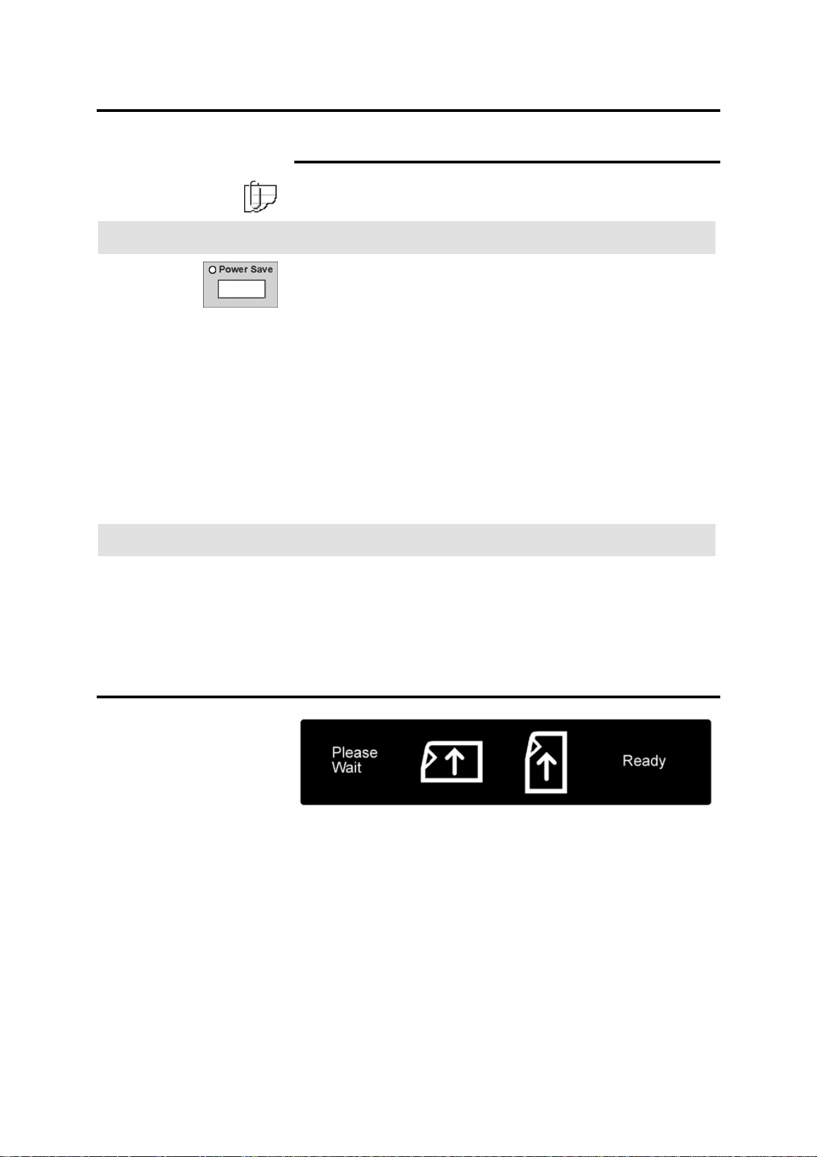
Introduction
The power save function reduces machine power consumption when
the machine is not used for a selected period of time.
When the machine enters the power save mode, current to the fuser
is reduced, and the electrical control signals (except auto mode
panel and scanner control panel) are switched off.
The power save feature in custom presets, can be set from 1 to 30
minutes, or the feature can be disabled entirely by entering No
minutes. The factory default is set to No minutes.
The interval timer clock is reset whenever the power save button is
pressed and the machine is currently in the power save mode.
If the machine is in power save mode and you would like to begin
making copies, press the power save button. Once the machine
completes the warm-up cycle and the ready to copy message is
displayed, you may begin coping again.
Procedure
1. Press the power save button.
The power save indicator lamp is lit.
The machine enters the power save mode.
2. To exit the power save mode, press the power save button.
Scanner document feed panel
The scanner document feed panel, located below the scanner
control panel, displays the document feed direction.
When the ready message is displayed, you can begin scanning your
documents.
28 Getting to know the MAX 200
Page 31

Auto mode panel
TTTT
Number Name Function
QQQQ
Media type
The media type column displays the preset media type for the
output media. For detailed information on how setup the media
type column, refer to page 196.
QQQQ
UUUU
RRRR
SSSS
VVVV
RRRR
SSSS
TTTT
UUUU
VVVV
Document size
Media supply
Media size matrix
Mode select button
Document feed
direction button
Each document size column refers to a document size, which can
be feed into the scanner. In auto mode, the panel displays the
document size that is feed into the scanner.
The media supply column displays the auto mode media supply
information, such as the roll number, tray or drawer number, and
the amount of media in each drawer or tray.
Note: To display the correct media supply information, ensure
the media type and series panel and the media series panel (tray
5), are set correctly. If needed, refer to page 38.
The media size matrix displays the output media size.
There are two modes of operations, auto or manual. If needed,
press the mode select button until the desired indicator lamp is lit.
The factory default is set to auto. For detailed information to set the
mode of operation, refer to page 212.
There are two feed directions, landscape or portrait. If needed,
press the document feed direction button until the desired feed
direction lamp is lit.
Note: The document feed direction button is disabled when
the machine is in manual mode.
Getting to know the MAX 200 29
Page 32

Printer control panel
Messages
Messages On condition
Please wait
Ready to copy/print
Copy/print
Warm-up
Manual mode
Close covers
Call for service
Turn printer off, then on
Replace toner bottle
Replace black toner
cartridge
Replace red toner
cartridge
• The machine condition before the ready to copy/print is
displayed.
• When machine operation has stopped due to a problem.
When the machine is in the ready condition.
When the machine is running copies.
During the machine warm-up cycle.
When the machine starts copying from the manual feed tray.
Indicates one of the printer doors is open.
When the machine detects an unrecoverable error that cannot be
recovered by a power-on reset.
When the machine detects on unrecoverable error.
When the machine detects the toner bottle is filled up to its maximum
capacity. To replace the toner bottle call for service.
When the machine detects the black toner cartridge is out of toner.
When the machine detects the red toner cartridge is out of toner.
Add media
30 Getting to know the MAX 200
Indicates the machine has run out of media. Check the appropriate
drawer or tray.
Page 33

Printer control panel (continued)
Messages (continued)
Message On condition
Remove output from
folder
Relatch fuser
Replace fuser web
Load media indicated
below
Made
Selected
When the machine detects the folder is full.
When the fuser is not correctly positioned.
When the fuser web needs to be replaced. To replace the web, call
for service.
Load media indicated below is displayed, when the machine detects
the selected media supply is empty.
The following media information is also displayed:
• Media series window displays the media series
• Roll or paper
• The type of media; vellum, bond or film
The made window displays the number of copies made. Increments
by one.
The selected window displays the copy quantity selected.
Increasing Toner
Diagnostics
Clear Jam
Getting to know the MAX 200 31
When the machine starts to increase toner.
When the machine is in diagnostic mode.
When the machine detects a media jam. Check the printer diagram
for the location of the jam.
Page 34

Printer control panel (continued)
Printer diagram
Indicator
lamp
1 - 5
6
7
8
9
10
11
12
Function
When a jam has occurred in the tray area, the respective indictor lamp is lit red.
When a jam has occurred between RFC drawer 1 and the xerographic area, the indictor
lamp is lit red.
When a jam has occurred between RFC drawer 2 and the xerographic area, the
indicator lamp is lit red.
When a jam has occurred between the manual feed tray and the xerographic area, the
indicator lamp is lit red.
When a jam has occurred before the xerographic area, the indicator lamp is lit red.
When a jam has occurred in the fuser area, the indicator lamp is lit red.
When a jam has occurred at the printer media exit area for the folder or stacker, the
indicator lamp is lit red.
When a jam has occurred at the printer media exit area, for the copy output tray, the
indicator lamp is lit red.
The roll 1 indicator lamp is lit, when the RFC drawer recognizes the specified media
series.
The roll 2 indicator lamp is lit, when the RFC drawer recognizes the specified media
series.
The roll 3 indicator lamp is lit, when the RFC drawer recognizes the specified media
series.
The roll 4 indicator lamp is lit, when the RFC drawer recognizes the specified media
series.
The tray 5 indicator lamp is lit, when tray 5 recognizes the specified media series.
When the black or red toner needs to be replaced, the toner indicator lamp is lit.
Approximately 2000 copies can be made after the indicator lamp is lit.
32 Getting to know the MAX 200
Page 35

Printer control panel (continued)
Top indicator lamps
There are three indicator lamps located at the top of the printer
control panel. The table below describes the condition of each
indicator lamp.
Green Amber
Color On condition
Green
Amber
Red
Note: The three indicator lamps flash at power-up.
When the printer is running.
When the machine is temporally unable to copy
because it is in the warm-up cycle, or is off line.
When the machine detects an a problem.
Red
Buttons
There are three buttons on the left side of the printer control panel
(not shown). The table below provides the name and function of
each button.
Button Function
Offline
Press to switch printer to offline or online.
Note: When the printer is offline, the offline
indicator lamp is lit.
Increase black
toner
Increase red
toner
Getting to know the MAX 200 33
Press the black button to increase black toner
onto the copies.
Press the red button to increase red toner onto the
copies.
Page 36

Manual feed panel
This section provides an overview of the manual feed panel
components.
Message On condition
Please wait
Remove media from
manual feed
Check printer control
panel
Insert media (set
media type)
Press start
Manual mode
Copy count
Button Function
Media type
When the machine is at a stop or the
machine has detected an error.
When the machine detects a media jam in
the insertion area of the manual feed tray.
The operator should check the printer control
panel.
When there is no media inserted at the start
of the manual feed copying.
When the machine detects media inserted in
the manual feed tray.
When making copies from the manual feed
tray.
When machine is making copies.
Press the media type button until the
desired media type is lit.
Start
Next document
Selection is displayed in the (set media
type) window.
After media is inserted and the media type
is selected, press the start button to begin
the copy process.
After making all copies of the current
document, press the next document
button, to copy the next scanned
document.
34 Getting to know the MAX 200
Page 37

Manual feed panel (continued)
Icon Function
Window Function
The portrait icon is lit when media needs to
be loaded in the portrait direction.
The landscape icon is lit when media needs
to be loaded in the landscape direction.
The window displays the number of copies
made. Increments by one.
The window displays the media width you
need to manually feed into the manual feed
tray.
Getting to know the MAX 200 35
Page 38

RFC panel
There are four RFC panels, one for each roll. Each panel displays,
the amount of media on each roll, the media roll number, the media
type and the media series information.
The RFC panels are located on right side of the printer. For detailed
information about the RFC media specifications, refer to the
appropriate chart in Media, starting on page 43.
For instructions on how to load roll media into the drawer, refer to
page 49.
Icon Function
Indicates the roll number in the RFC drawer.
The media supply indicator lamp displays the
amount of media on the roll. When the roll is empty,
there are no horizontal lines lit.
Message Function
Displays the media type. Media type is set from the
media type and series panel, on page 38.
Window Function
Displays the media width for the selected series.
Media series is set from the media type and series
panel, on page 38.
Button Function
Press the trim button to perform the auto cut
function on roll media. For detailed information on
how to use the trim button, refer to page 52.
Note: To enable the trim function, the printer
must be offline.
36 Getting to know the MAX 200
Page 39
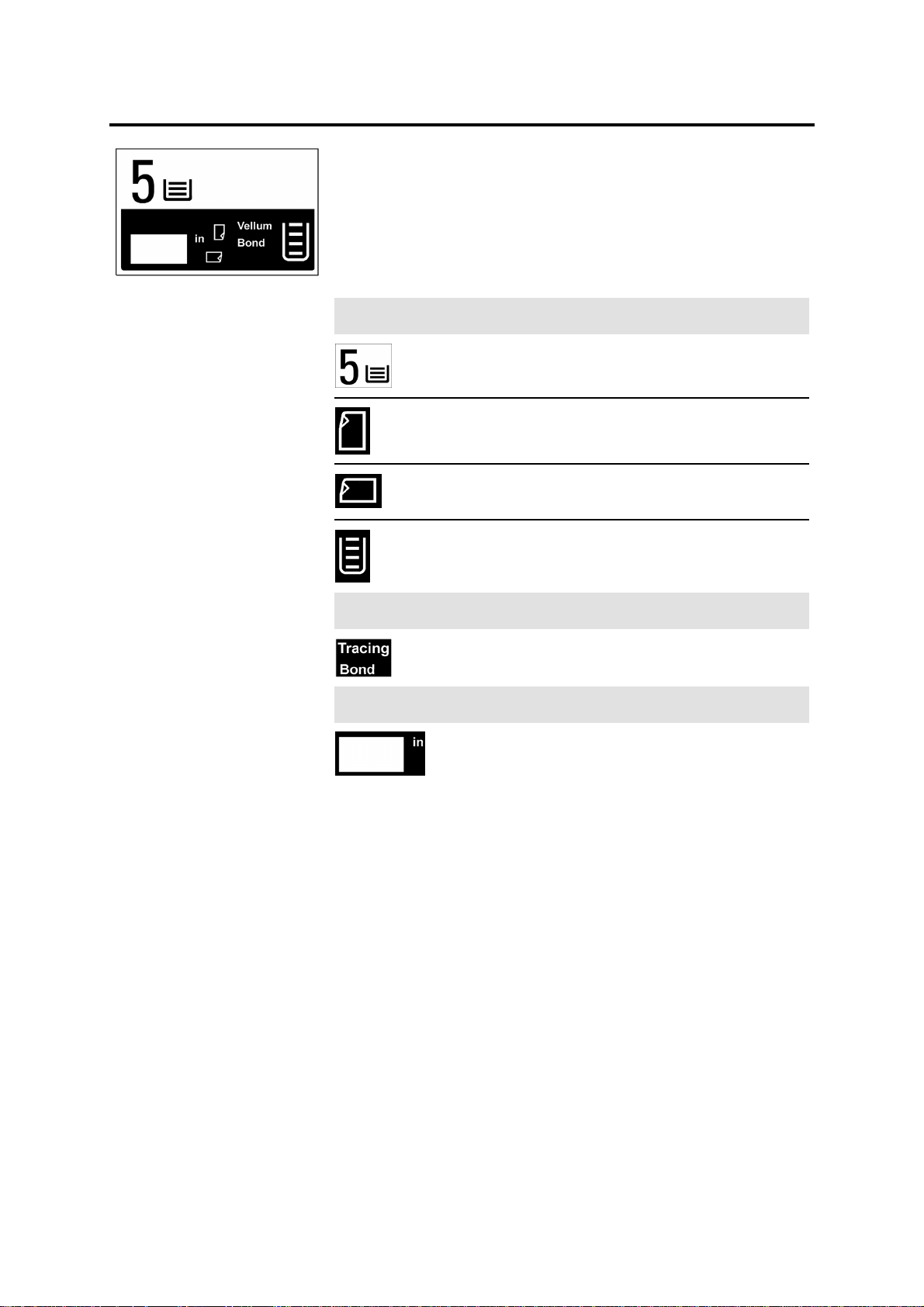
Cut sheet panel
The cut sheet tray, also know as tray 5, supplies bond media and
has a tray capacity of 1000 sheets (20 –24 lb.). Media can be
loaded, short edge or long edge feed.
For detailed information about the media specifications, refer to the
appropriate chart in Media, starting on page 43.
For instructions on how to load media into the tray 5, refer to page
51.
Icon Function
The 5 icon indicates the cut sheet tray, tray 5.
The portrait indicator lamp is lit when the feed
direction from the cut sheet tray is portrait.
The landscape indicator lamp is lit when the feed
direction from the cut sheet tray is landscape.
The media supply indicator lamp displays the amount
of media in tray 5. When the tray is empty, there are
no horizontal lines lit.
Message Function
Displays the bond media type only.
Window Function
Displays the media width for the selected series. The
media series is set from the media series panel
(tray 5), on page 38.
Getting to know the MAX 200 37
Page 40

Media type and series panel
There are four media type and series panels, one for each roll. They
are located next to each roll in the RFC drawer. This section
provides an overview of the media type and series panel
components.
For detailed information about the RFC media specifications, refer to
the appropriate chart in Media, starting on page 43.
Name Function
Media series Set the dial to the correct media series.
Media type Set the dial to the correct media type.
Window Function
When the drawer is closed, the RFC panel window
displays the media series.
When the drawer is closed, the RFC panel displays
the media type.
When the drawer detects media the indicator lights.
Media series panel (tray 5)
The media series panel is located in the cut sheet tray, tray 5.
For detailed information about the cut sheet tray media
specifications, refer to the appropriate chart in Media, starting on
page 43.
Note: Only bond media can be loaded into tray 5.
Name Function
Media series Set the dial to the correct media series.
Note: The media type and series panel in this
example is for roll 1.
When the tray is closed, the cut sheet panel
window displays the media width for the selected
series.
38 Getting to know the MAX 200
Page 41
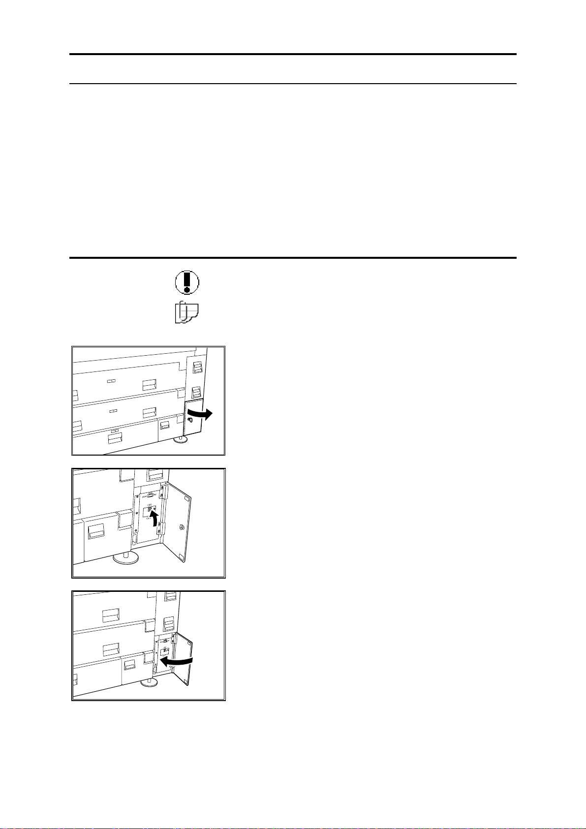
MAX 200 power
The Max 200 power chapter provides machine power information.
The following topics are discussed:
• Switching the power-on
• Switching the power off
• Ground fault protectors
• Warm-up
• Auto power-off
• Power save
Switching the power-on
Caution: Never switch off the printer or scanner when the printer is
in operation.
Note: This procedure is for the printer and scanner only. If your
system contains the folder or stacker, refer to their user guide for
power-on instructions.
1. Turn the key and open the printer circuit breaker
door.
2. Switch the printer circuit breaker to the on position
(up).
3. Close the printer circuit breaker door and turn the
key to lock the door.
MAX 200 power 39
Page 42

Switching the power-on (continued)
4. Switch the printer power-on.
The switch is located above the door.
5. Position the scanner circuit breaker switch to the on
position (up).
The scanner circuit breaker is located at the lower
rear right corner.
6. Switch the scanner power-on.
Switching the power off
WARNING: The machine power switch does not break power to
the low voltage power supply, to remove power from the
machine disconnect the power cord.
Note: This procedure is for the printer and scanner only. If your
system contains the folder or stacker, refer to their user guide for
power-off instructions.
1. Switch the scanner power off.
The printer power is automatically switched to the off
position.
40 MAX 200 power
Page 43
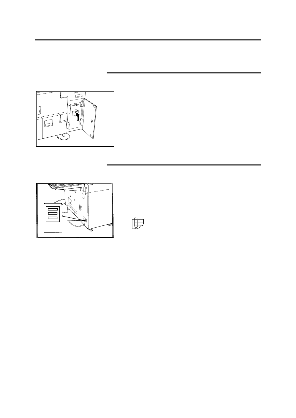
Ground fault protectors
In the event that the MAX 200 experiences an unexpected power
loss, check the printer and scanner ground fault protectors.
Printer ground fault
In case of a printer power loss, perform the procedure below:
Scanner ground fault
In case of a scanner power loss perform the procedure below:
1. Open the printer circuit breaker door.
2. Position the ground fault up.
If the test indicator remains lit, call your Xerox
Engineering Systems service representative.
If the color red is not displayed in the top ground fault
window, press the bottom red reset button.
If the ground fault window still does not have red
displayed, call your Xerox Engineering Systems service
representative.
Note: Ensure the scanner circuit breaker is in the
up position.
MAX 200 power 41
Page 44

Warm-up
When the MAX 200 is switched on, the machine enters a warm-up
cycle and the please wait message is displayed on the touch screen
and the printer control panel. The warm-up cycle is approximately 5
minutes at 72
During the warm-up cycle the scanner does not respond to button
selections. When the ready to copy message is displayed on the
touch screen and ready to copy/print is displayed on the printer,
you can begin to scan documents or select any touch screen feature
or option.
Auto power-off mode
When the machine is not used for a selected period of time, the auto
power-off feature switches the machine power to off. To exit the auto
power-off mode, you must power-on the machine. For detailed
information on how to power-on the MAX 200, refer to page 39.
Once the machine completes the warm-up cycle, and the ready to
copy message is displayed, you may begin copying again.
The auto power-off timer can be set from 1 to 5 hours, or the feature
can be disabled entirely by entering No minutes. The factory default
is set to No minutes.
o
C, 55% humidity.
Power save
For detailed information on how to change the auto power-off mode
default, refer to page 177.
The power save function reduces machine power consumption when
the machine is not used for a selected period of time. The current to
the fuser is reduced, and the electrical control signals (except the
control panels) are switched off.
To exit the power save mode press the power save button, located
on the scanner control panel.
Once the machine completes the warm-up cycle, and the ready to
copy message is displayed, you may begin coping again.
The power save timer can be set from 1 to 30 minutes, or the feature
can be disabled entirely by entering No minutes. The factory default
is set to No minutes.
For detailed information on how to change the power save default,
refer to page 178.
42 MAX 200 power
Page 45
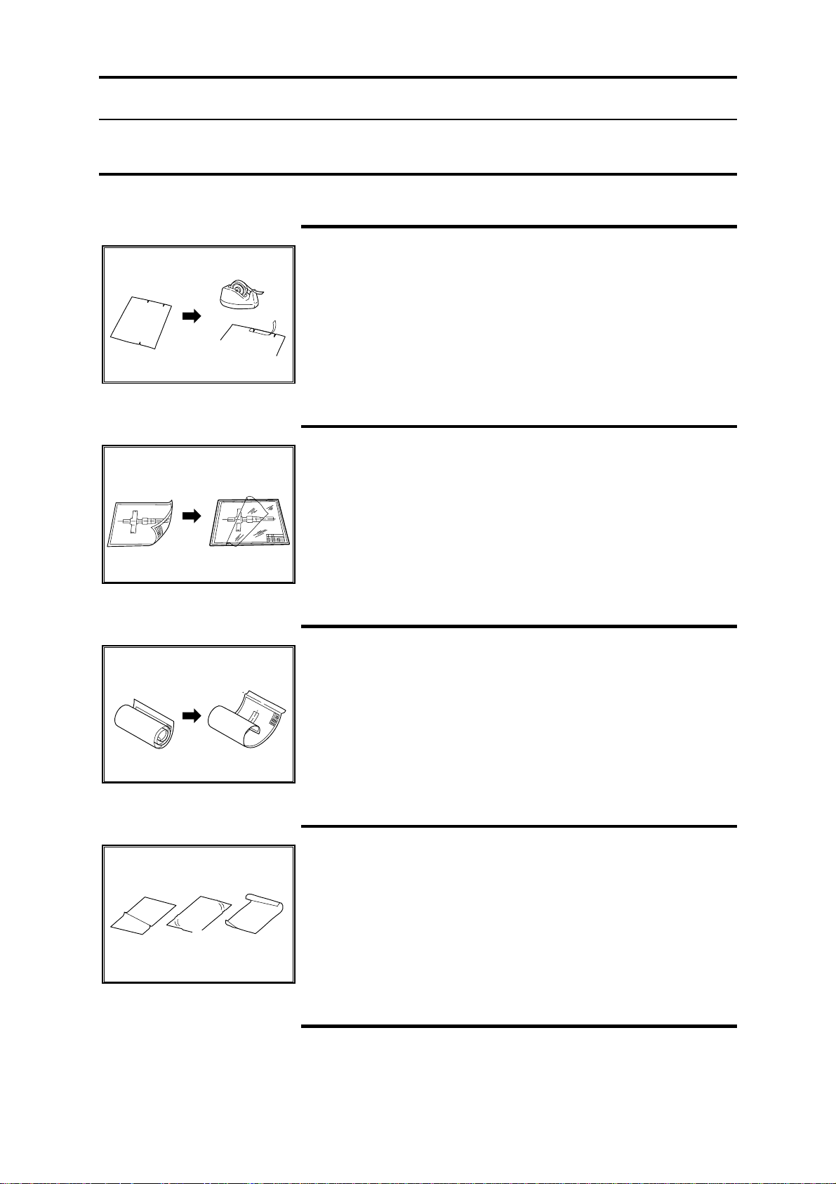
Media
How to handle unusable documents
Torn or ripped document
1. Mend the torn portion by affixing tape on the reverse side.
2. If the lead edge is frayed, mend it with tape.
Document with staples
1. Remove the staples.
2. Mend the torn portion by affixing tape on the reverse side.
3. If the lead edge is frayed, mend it with tape.
Document with curl
1. Roll the document in reverse to straighten the curl.
2. If the curl cannot be straightened, fold the original document
once along the line about 20-30 mm from the lead edge, then
flatten the original document before copying it.
3. If media has excessive curl, do not use.
Bent document
Do not use creased, wrinkled, or excessively curled document.
Transparent document
Copy the transparent document, with it loaded in the doc ument
carrier.
Media 43
Page 46

How to store cut sheet media
• Store the cut sheet media flat, not on edge.
• Store open media in original wrap and seal.
• Do not expose to moisture or sunlight.
How to store roll media
• Store roll media on end.
• Store open media in original wrap and seal.
• Do not expose to moisture or sunlight.
44 Media
Page 47

Media type and weight charts
The media specification charts in this section, provide media type
and weight information.
Media type Media types and weights
RFC drawer and manual feed tray
Bond
Vellum
Film
20 lb. Xerox 4024 Engineering smooth
20 lb. Xerox 4024 DP
20 lb. Xerox image series smooth recycled engineering bond
20 lb. Xerox improved zero-solvent vellum
17 lb. Xerox zero solvent vellum
20 lb. Improved erasable vellum
4mil Zero solvent accu-image film
3mil Aqueous film
RFC media size parameters
Minimum width: 11 inch
Maximum width: 36 inch
3 in. core diameter with 500 ft. or 650 ft. bond or vellum
3 in. core diameter with 150 ft. film
Manual feed tray media size parameters
Minimum width: 8.5 inch
Maximum width: 36 inch
Minimum length: 8.5 inch
Maximum length: 19 feet 8 inches
Media type Media weights
Bond
20 –24 lb.
Cut sheet tray media size parameters
11 x 17 inch, 12 x 18 inch (short/long edge feed)
8.5 x 11 inch, 9 x 12 inch (short/long edge feed)
Cut sheet tray (tray 5)
Media 45
Page 48
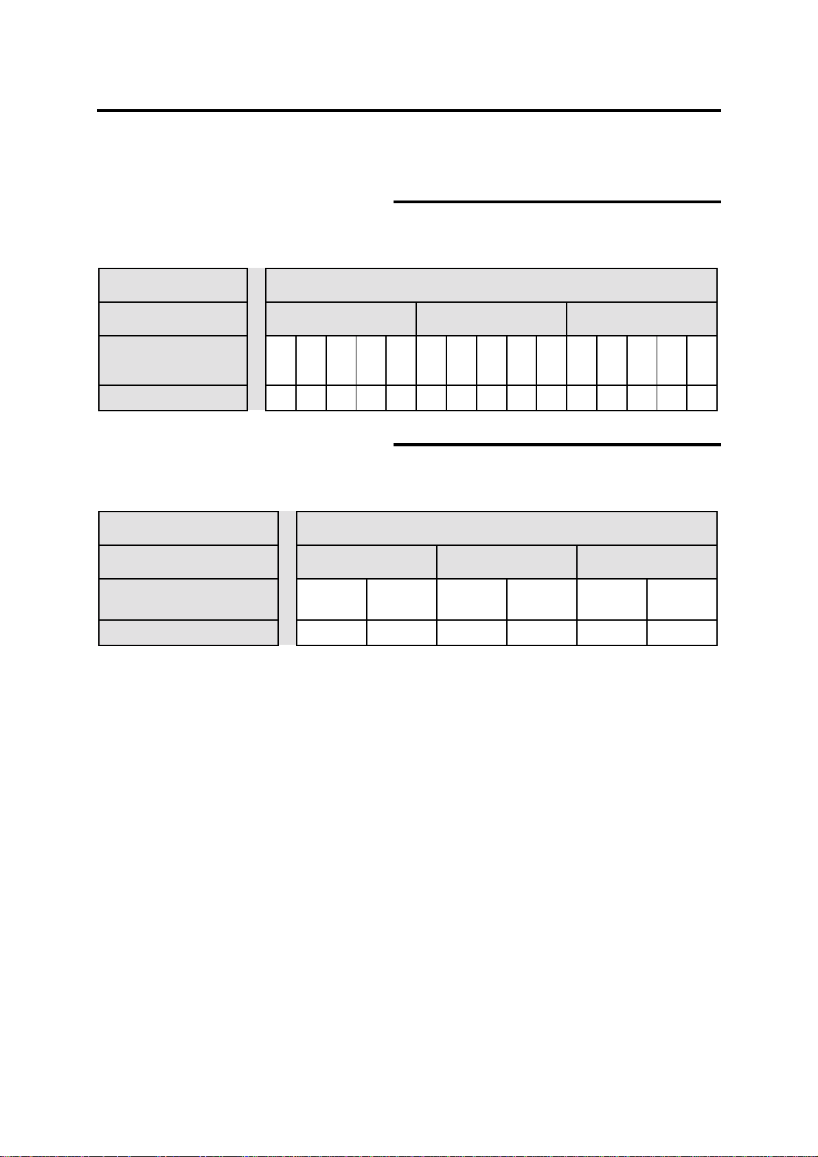
Media size charts
The media size specification charts in this section provide media size
roll, cut sheet, and manual feed tray information.
RFC drawer
A: Supports auto and manual mode
M: Supports only manual mode
Standard
Selection of switch 9 inch series 8.5 inch series ISO A series
Size
Supports
36
in.30in.24in.18in.12in.34in.30in.22in.17in.11in.
AMAAAAMAAAAAAAA
841mm594mm420mm297mm210
Tray 5
A: Supports auto and manual mode
M: Supports manual mode only
Standard
Selection of switch 9 inch series 8.5 inch series ISO A series
Size
Supports
12 x18
inch
AAAAAA
Tray capacity is 1000 sheets (20 –24 lb.).
Supports pre-punches sheet media (2, 3, and 4 hole)
9 x 12
inch
11 x17
inch
8.5 x 11
inch
297 x 420mm210 x 297
mm
mm
46 Media
Page 49

Media size charts (continue d)
Manual feed tray
M: Supports manual mode only
Width
Size
Supports
36
inch34inch30inch24inch22inch18inch17inch12inch11inch
MMMMMMMMMMMMM
Maximum scan length
MAX 200 maximum scan length is 49.3 feet (15 m), Xerox Engineer
Systems guarantees copy quality up to 32.8 feet (10 m).
Maximum print length
The MAX 200 print length can be set up to 62.4 feet (19 m). Xerox
Engineer Systems guarantees print quality up to 19.7 feet (6 m). If
needed, your service representative can set the maximum printer
length to; 19.7 feet (6 m), 32.8 feet (10 m), 49.3 feet (15 m), or
62.4 feet (19 m).
*The maximum print length for E-sorter function is 13.5 feet (4.1 m).
841mm594mm420mm297
mm
Media 47
Page 50

How do I know when tray 5 or a drawer is empty?
The symbol on the left is called the media supply indicator. It is
displayed on various MAX 200 components to help you determine
the tray or drawer condition. This section identifies the MAX 200
components that display the media supply indicator.
From the auto mode panel
When the MAX 200 is in auto mode, the media supply indicators are
displayed on the auto mode panel.
The media supply indicator lamps are located on the far right
column, of the auto mode panel. The bars within the indicator lamp
reflect the amount in the tray or drawers. When there are no bars
displayed, the specified tray or drawer is empty.
From the R/E, media, cut touch screen
When the MAX 200 is in manual mode, the media supply levels are
displayed on the R/E; media; cut touch screen.
The media supply icons are located next to the R/E; media; cut
option buttons. The bars within each icon reflect the amount of
media on each roll or in tray 5. When there are no bars displayed,
the specified roll or tray is empty.
From the RFC panel
The media supply indicator lamp is located on the lower right side of
the RFC panel. The bars in the indicator lamp reflect the amount of
media left. When the media supply indicator displays no bars there
is no media on the roll.
From the cut sheet panel
The media supply indicator lamp is located on the right side of the
cut sheet panel. The bars within in the indicator lamp reflect the
amount of media in the tray. When the media supply indicator
displays no bars the tray is empty.
48 Media
Page 51

How to load roll media
Introduction
When roll media runs out, the printer control panel displays the
messages, add media and load media indicated below.
Perform the following procedure when you need to load roll media
into the machine.
Procedure
1. Pull out the RFC drawer.
2. Remove the mandrel and empty roll from the RFC
drawer.
3. Push down on the mandrel release lever, and pull the
used media core off of the shaft.
Media 49
Page 52
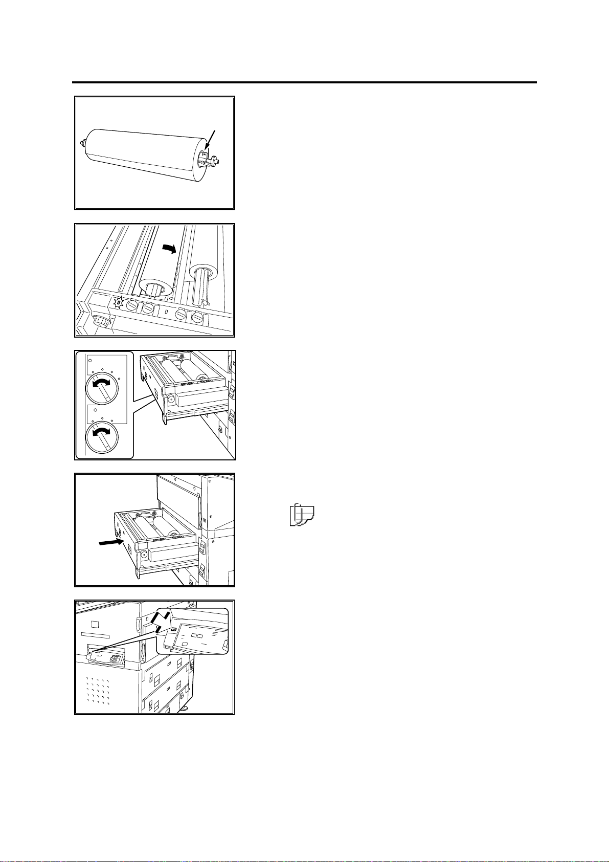
How to load roll media (continued)
4. Push down on the mandrel release lever, and insert
the mandrel into the new media roll.
5. Align the edge of the media to the size indicators on
the mandrel.
6. Place the mandrel back into the drawer.
7. Rotate the media lead edge clockwise and position
the media lead edge, under the roll.
8. Continue to rotate clockwise until you here a beep.
• If you hear an intermittent beep, take up the
media slightly and rotate the media clockwise
again.
The media indicator lamp is lit.
9. Use the dial on the media type and series panel, and
set to the correct media series and type.
10. Push in the RFC drawer gently back into the
machine.
Note: Ensure the correct media series and type
is displayed on the RFC panel. If not, ensure the
media series and type panel is set correctly.
11. Press the offline button, on the printer control panel.
The printer is offline.
12. Press the trim button, on the RFC panel.
The trim indicator lamp is lit and the trimmed media is
sent to the printer copy output tray.
13. Press the offline button.
The printer is online.
14. Remove the trimmed media from the copy output
tray.
50 Media
Page 53

How to load cut sheet media
Introduction
The cut sheet tray capacity is 1000 sheets (20 –24 lb.). The cut
sheet tray holds 8.5 x 11 inch to 12 x 18 inch bond media (short edge
or long edge feed).
Perform the following procedure when you need to load cut sheet
media into tray 5.
Procedure
1. Pull out the cut sheet tray.
2. Load the media short edge or long edge feed. Refer
to the media size label in the tray.
3. Adjust the guides to the media size.
Do not force the guides against the edges of the cut
sheet stack.
4. Use the dial on the media series panel (tray 5), and
set to the correct media series.
5. Push the tray in until it stops.
Note: Ensure the correct media series is
displayed on the cut sheet panel. If not, ensure the
media series panel (tray 5) is set correctly.
Media 51
Page 54

How to cut roll media
Introduction
The MAX 200 provides two roll cut methods, auto and manual.
Procedure
Auto cut,
page 52.
Manual cut,
page 53.
Auto c ut
When the trim button is pressed, the machine
automatically cuts the roll media.
When a new roll is loaded into the drawer, use this
cut method to ensure a smooth cut.
The operator uses the cutter knob to cut the media.
Use this method, when a media jam occurs and the
media jam length is very long. When the cutter knob
is used, media is cut at a slight angle.
1. Press the offline button, on the printer control panel.
The printer is offline.
2. Press the trim button, on the RFC panel.
When the machine cuts the media, the trim indicator
lamp is lit.
The trimmed media is sent to the printer copy output
tray and the trim indicator lamp is off.
4. Remove the cut media, from the copy output tray.
5. Press the offline button.
The printer is online.
52 Media
Page 55
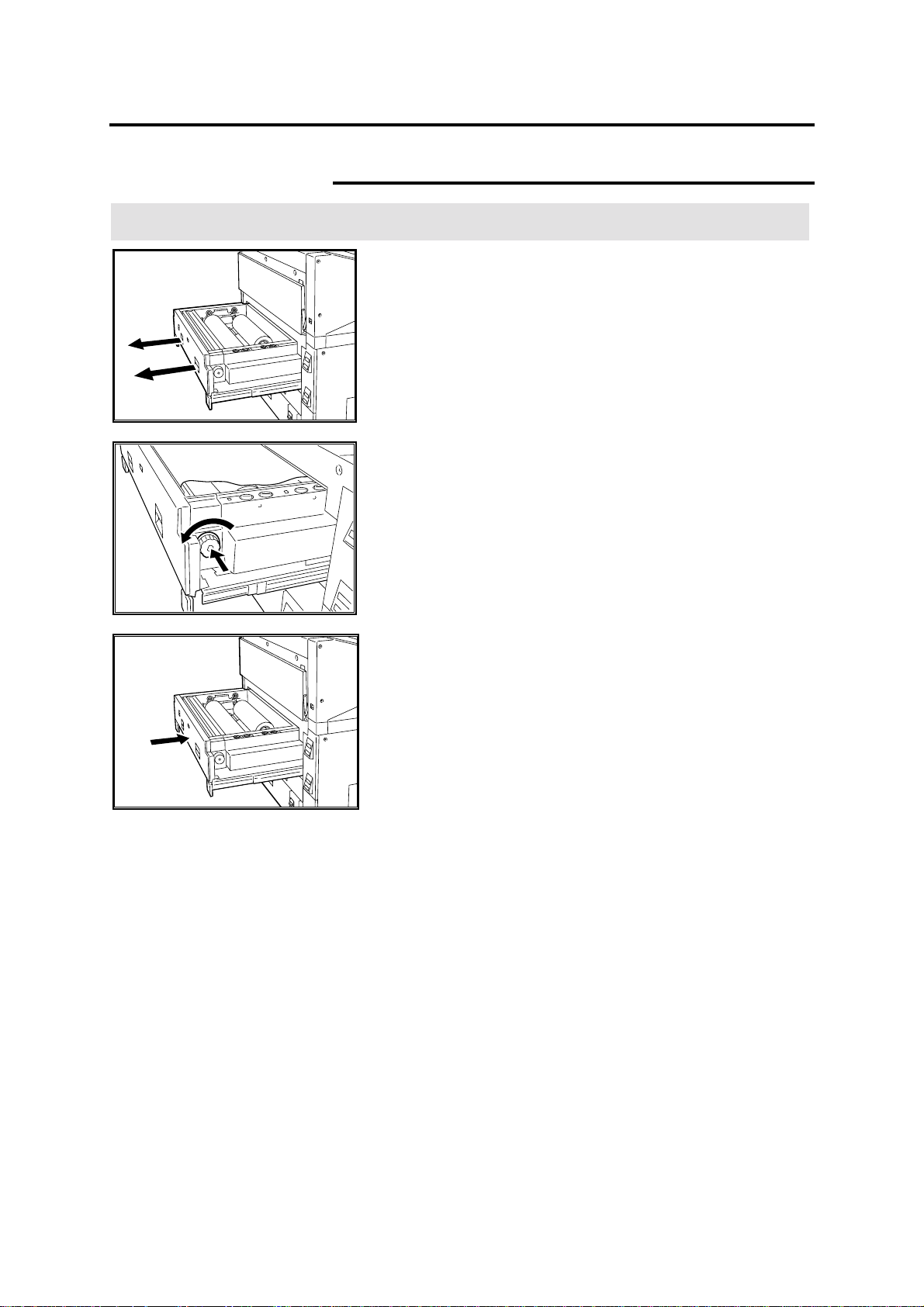
How to cut roll media (continued)
Manual cut
Procedure
1. Open the desired RFC drawer.
2. Press and release the cutter knob.
3. Rotate the cutter knob counterclockwise, to cut the
media.
4. Remove the cut media from the drawer.
5. Push the RFC drawer gently back into the machine.
Media 53
Page 56

Heater
Introduction
Procedure
The heater reduces the moisture contained in the media. If the room
humidity is high, switch the media heater to on.
Note: When the printer is switched off, the heater remains on. In
order to switch the heater off, the printer breaker switch must be off.
1. Turn the key and open the printer circuit breaker
door.
2. Position the media heater switch to on.
3. Close the printer circuit breaker door and turn the key
to lock the breaker door.
54 Media
Page 57

Humidifier (optional)
Introduction
The humidifier is an optional accessory and adds moisture to the
media. Depending on the amount of humidity in the room, the
humidifier is automatically switched on.
Note: When the printer is switched off, the humidifier remains on. In
order to switch the humidifier off, the printer breaker switch must be
off.
Note: The humidifier and the heater can not be activated at the
same time.
Procedure
1. Turn the key and open the printer circuit breaker
door.
2. Position the right switch to humidifier.
3. Position the left switch to on.
Note: You can only switch the heater or the
humidifier on, both can not be set to On at the same
time.
4. Close the printer circuit breaker door and turn the key
to lock the breaker door.
Media 55
Page 58

How to make copies
Before making copies
Before using the MAX 200 you need to determine what standard
series the MAX 200 will recognize: 8.5 inch series or 9 inch series.
The Custom Presets feature, Document Width, sets up the default
series the machine recognizes.
If your machine is set up to recognize the 8.5 inch series, all output
lengths are based on the standard paper sizes shown below:
If your machine is set up to recognize the 9 inch series, all output
lengths are based on the standard paper sizes shown below:
56 How to make copies
Page 59
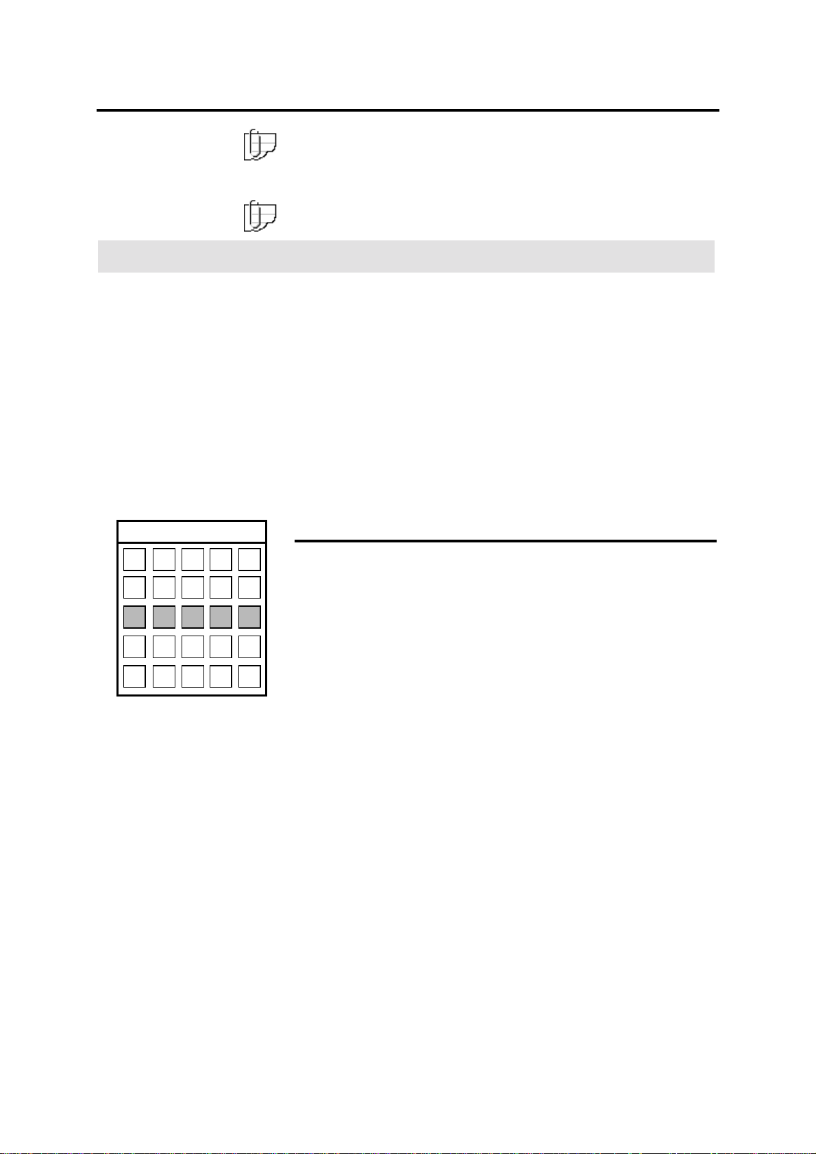
In auto mode
Introduction
Note: When the selected feed direction is landscape, the E size row
and column on the auto mode panel is not available. The maximum
document width for scan is 36 inches, an E size landscape
document width is 44 inches.
Note: To go directly to the auto mode procedure, go to page 58.
When MAX 200 is in auto mode, all output lengths are based on the
standard paper size set in Custom Presets, 8.5 inch or 9 inch.
The following features are available for auto mode:
• Auto R/E – Copies are printed automatically reduced or
enlarged per your selection
• Auto 100% - Copy at 100%
• Cut roll media – Standard or synchronize
• Add/remove margins – you can add up to 999 mm or remove
up to 90 mm margins in 1 mm increments to either the lead or
trail edge of your copy (enabled with synchronize)
EDCBA
E E E E E
D D D D D
C C C C C
B B B B B
A A A A A
Auto R /E
For example, you want all of your documents to be printed on C-size
media (shaded buttons), but your input documents are a combination
of different size drawings (E, D, C, B and A).
First select C-size media under each document size. The machine
then automatically reduces the E and D-sizes to C-size, the C-size
document is copied at 100%, and the B and A-size documents are
enlarged to C-size.
How to make copies 57
Page 60

In auto mode (continued)
y
01
EDCBA
E E E E E
D D D D D
C C C C C
B B B B B
A A A A A
Procedure
Auto 100%
In the next example you have multiple size documents and you want
each copy to be printed at 100%. For this example, you would select
the media size shown to the left (shaded buttons). The machine
automatically prints the copies at 100%.
Cut roll media
• Standard cuts roll media to the length of standard paper sizes.
• Synchronize cuts roll media to the length of the original up to
19.8 feet (6 m) long for a 11 inch (279 mm) wide original.
To activate synchronized cut mode, you need to enable the auto
mode-synchronized media cut default to enable in Custom Presets.
For detailed refer to page 192.
1. Ensure the auto mode indicator lamp is lit. If not, press the
mode select button, until the auto mode indicator lamp is lit.
2. Determine the document size to be scanned (A to E).
3. Select the desired output media size (A – E), for each document
to be scanned, on the auto mode panel.
Ready to cop
Load documents face down
Basic
Auto Mode
R/E; Media;
Cut
Image Quality Additional Finishing
Black Red
Image
Density
Line
Fixed
Document
Image Type
Selected
Black Only
Print Color
4. Select the desired basic copying features. If needed, refer to
page 68.
58 How to make copies
Page 61

In auto mode (continued)
y
y
y
01
Ready to cop
Load documents face down
Basic
Sharpness
Image Quality Additional Finishing
Scan Color
Sensitivity
Selected
01
6. Select the desired image quality features. If needed, refer to
page 92.
Ready to cop
Load documents face down
Basic
Image Quality Additional Finishing
Selected
01
Off Off
Image
Location
Editing
7. Select the desired additional features. If needed, refer to page
95.
Ready to cop
Load documents face down
Basic
Off Off
Image Quality Additional Finishing
StamperE-sorter Folder
Selected
8. Select the desired finishing features. If needed, refer to page
129.
9. Enter the copy quantity.
10. Ensure the document exit guide is positioned correctly. If
needed, refer to page 16.
11. When the ready to copy message is displayed, insert the
document face down along the guide.
How to make copies 59
Page 62

In manual mode
Introduction
When MAX 200 is in manual mode, all output lengths are based on
the same auto mode standard sizes and the nonstandard size
30 x 42 inch.
The following features are available for manual mode:
• Manual 100% - Copy at 100%
• Manual R/E – Reduce or enlarge your copies from 25% to 400%,
0.1% increments are available
• Cut roll media – Standard, synchronized, long copy or variable
length
• Add/remove margins – you can add up to 999 mm or remove
up to 90 mm margins in 1 mm increments to either the lead or
trail edge of your copy (enabled with synchronize and long copy)
• Manual feed mode – Enable the manual feed tray
Documents can be scanned, short edge or long edge feed. If the
scanned document size does not match the selected magnification
and output media size, an error message is displayed.
60 How to make copies
Page 63

In manual mode (continued)
y
01
y
01
Procedure
1. Ensure the MAX 200 is in manual mode. If needed press the
mode select button until the manual mode lamp is lit.
2. Select the basic feature group tab.
The basic feature group screen displayed.
Ready to cop
Load documents face down
Basic
Selected
Image Quality Additional Finishing
Auto Mode
R/E; Media;
Cut
Black Red
Image
Density
Line
Fixed
Document
Image Type
3. Select R/E; media; cut.
The R/E; media; cut screen is displayed.
Ready to cop
Load documents face down
R/E; Media; Cut Cancel Done
100.0%
Normal R/E
R/E by L&W
100.0%
36” Bond
24” Bond
24” Bond
18” Vellum
12”x18” Bond
Synchronized
Paper Length
Manual Feed
3. If needed, select the desired R/E.
Black Only
Print Color
Selected
Adjustment
Normal R/E
One of six preset percentages may be selected,
or any percentage within the available range may
be entered.
R/E by L&W
Two different percentages may be selected, one
for the length and one width.
100.0%
Same as document.
4. Select the desired media source (roll 1 – roll 4, or tray 5).
When roll media is selected, the paper length adjustment feature
is enabled. If needed, select this button to select the desired cut
mode. For detailed information, refer to page 79.
5. Select done.
The basic feature group screen is displayed.
How to make copies 61
Page 64
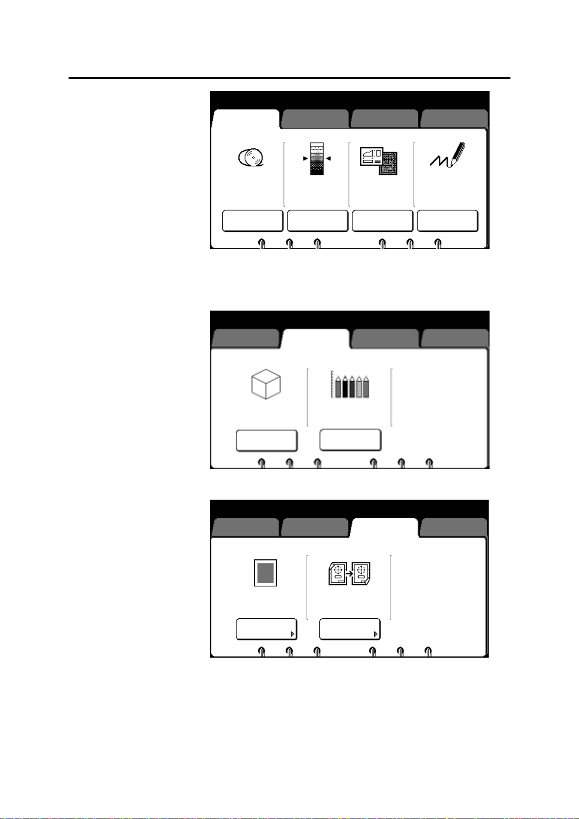
In manual mode (continued)
01
y
y
01
y
01
Ready to cop
Load documents face down
Basic
Image Quality Additional Finishing
Selected
1
Bond
100.0%
R/E; Media;
Cut
Black Red
Image
Density
Line
Fixed
Document
Image Type
Black Only
Print Color
6. Select other desired basic copying features. If needed, refer to
page 68.
7. Select the desired image quality features. If needed, refer to
page 92.
Ready to cop
Load documents face down
Basic
Image Quality Additional Finishing
Selected
Sharpness
Scan Color
Sensitivity
8. Select the desired additional features. If needed, refer to page
95.
Ready to cop
Load documents face down
Basic
Off Off
Image
Location
Image Quality Additional Finishing
Editing
Selected
62 How to make copies
Page 65
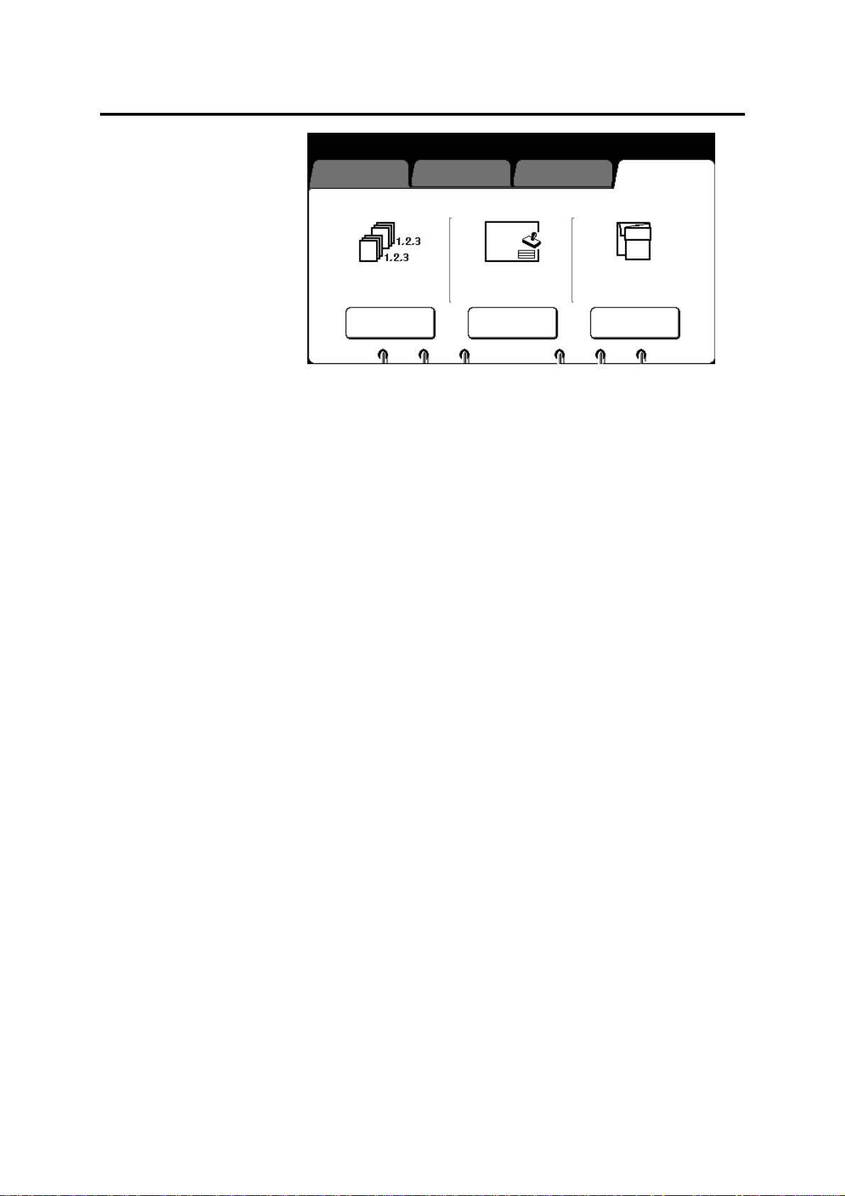
In manual mode (continued)
y
01
Ready to cop
Load documents face down
Basic
Off Off
Image Quality Additional Finishing
StamperE-sorter Folder
Selected
Fan
9. Select the desired finishing features. If needed, refer to page
129.
10. Enter the co p y quant it y.
10. Ensure the document exit guide is positioned correctly. If
needed, refer to page 16.
11. When the ready to copy message is displayed, insert the
document face down along the guide.
How to make copies 63
Page 66
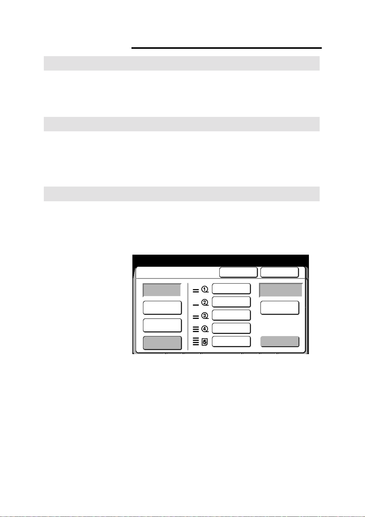
Introduction
y
01
Helpful hints
Procedure
With the manual feed tray
Using the manual feed tray is useful when the correct size or type of
media is not loaded in the printer, or when you want to make a copy
on special size media (A – E).
Refer to the helpful hints before using the manual feed tray
procedure on page 64.
• The manual feed mode is available with the combination of the
stamper and E-sorter.
• The stamper feature can be used with manual feed.
• Not avail able wh en the E-s ort er is bei ng used.
• Copies made with the manual feed tray, can not be folded.
1. Ensure MAX 200 is in manual mode. If needed, press the mode
select button until the manual mode lamp is lit.
2. Select the basic feature group tab.
3. Select R/E; media cut.
The R/E; media; cut screen is displayed.
Ready to cop
Load documents face down
R/E; Media; Cut Cancel Done
100.0%
Normal R/E
R/E by L&W
100.0%
36” Bond
24” Bond
24” Bond
18” Vellum
12”x18” Bond
4. Select manual feed.
The manual feed screen is disp layed.
Selected
Synchronized
Paper Length
Adjustment
Manual Feed
64 How to make copies
Page 67

With the manual feed tray (continued)
A
Ready for manual feed (standard size)
Load documents face down
Manual Feed
Cancel Done
Only one nonstandard
document may be loaded
for manual feed, regardless
of size
Nonstandard
5. Select nonstandard or standard.
Standard
The number of standard sized documents that
can be scanned at one time depends on the
memory capacity and document size.
Nonstandard
Only one nonstandard document can be
scanned at a time.
Ready for manual feed (standard size)
Load documents face down
Manual Feed
R/E: 100.0%
Multiple standard
documents may be loaded
for manual feed, up to
available memory capacity
Standard
fter loading all
documents, press [Done]
Change Setup
Press [Clear All] on panel to stop operation
Done
6. Insert each document in your document set into the scanner and
follow steps 5a or 5b, after each document is scanned.
a. If your scanned document requires any copy feature
changes, select the change setup button and go to step
14.
b. When all your documents have been scanned and there are
no required copy feature changes, select the done button.
Continue to the next step.
6. Open the manual feed tray.
How to make copies 65
Page 68

With the manual feed tray (continued)
01/04
7. Press the media type button, until the desired media type is
displayed.
• The media series is displayed in the insert media window.
8. Insert the media into the manual feed tray in the direction that is
displayed on the manual feed panel (landscape or portrait).
• Ensure to align the media between the guidelines, on the
manual feed tray. The machine will grip the media and feed
it in slightly.
• The press start message is displayed when the media is
loaded correctly.
9. Press the start button, on the manual feed panel, to start
copying.
• To make additional copies of the same scanned document,
press the start button again.
• The number of copies made is displayed in the copy count
window.
10. If needed, press the next document button, to make copies of
your next scanned document. Else continue to the next step.
To make multiple copies of the same document repeat step 9.
11. Repeat step 10 until all scanned documents have been copied.
12. To exit the manual feed mode, press the stop copy button on
the scanner control panel. Stop here.
Ready to Copy (E-Sort/Collated)
Load document face down
Change Setup
Media Standard
R/E
Image B: Normal
Density R: Norm al
Document Line/
Image Type Fixed
Print Blac k Only
Image Off
Location
Editing Off
Close
Sharpness Normal
Background Off
Suppression
Scan Color Off
Stamper Off
Counted
The change setup screen is displayed.
13. Select the desired feature you want to change.
• The first column of text, next to the feature button, is the
name of the copy feature.
• The second column of text, displays the selected feature
option.
14. When the copy feature screen is displayed, make your
changes. Select done to return to the change setup screen.
The change setup screen is displayed.
66 How to make copies
Page 69

With the manual feed tray (continued)
01/04
Ready to Copy (E-Sort/Collated)
Load document face down
Change Setup
Media Standard
R/E
Image B: Normal
Density R: Norm al
Document Line/
Image Type Fixed
Print Blac k Only
Image Off
Location
Editing Off
Close
Sharpness Normal
Background Off
Suppression
Scan Color Off
Stamper Off
Counted
15. If additional changes are required for the scanned
document, repeat steps 13 and 14.
When all feature changes are complete for the scanned
document, select the close button and go to step 5.
How to make copies 67
Page 70

Basic touch screen features
y
01
The basic features provide access to the most common copy
features used.
Procedure
Ready to cop
Load documents face down
Basic
Auto Mode
R/E; Media;
Cut
Image Quality Additional Finishing
Black Red
Image
Density
Line
Fixed
Document
Image Type
Selected
Black Only
Print Color
Procedure to access the basic feature group screen:
1. Select the basic feature group tab.
The basic feature group screen is displayed.
2. Go to the desired selection.
• Media cut mode, (when in auto mode and synchronized cut
mode is enabled), go to page 69.
• R/E; media; cut, page 69.
• Image density, page 87.
• Document image type, page 88.
• Print color, page 90.
68 Basic touch screen features
Page 71

Media cut mode
Introduction
When in auto mode you can choose synchronize cut by enabling the
auto mode –synchronized media cut default, in Custom Presets
(page 192). Synchronize cuts roll media to the length of the original
up to 19.8 feet (6 m) long.
1. Select media cut mode.
2. Select Synchronized.
3. If needed, you can add up to 999 mm or remove up to
90 mm to the trail or lead edge margin. Use the arrow
buttons or ±±±±100 buttons to enter the desired measurement.
Select clear to clear wrong data.
4. Select done.
Basic touch screen features 69
Page 72

R/E; media; cut
y
01
Introduction
When the R/E; media cut mode screen is displayed the following
manual mode features are available to you:
• Manual 100% - copy at 100%
• Manual R/E – reduce or enlarge your copies using normal R/E,
R/E by L&W, or R/E calculate. These features allow you to
reduce or enlarge copies from 25 to 400%.
• Cut roll media – use one of the cut modes; standard,
synchronized, long copy or variable length
• Manual feed tray – enables the manual feed tray mode, refer to
64.
Ready to cop
Load documents face down
R/E; Media; Cut Cancel Done
Selected
Normal R/E
R/E by L&W
Option Function
Normal R/E
One of six preset percentages may be selected, or any percentage
within the available range may be entered. Refer to page 71.
R/E by L&W
Two percentages may be selected, one for the length and one for
the width. Refer to page 73.
R/E calculator
The percentage is automatically calculated based on the document
and copy size. There are two calculators available, one for normal
R/E and one for R/E by L&W (for manual mode).
• To refer to the normal R/E calculator, refer to page 75.
• To refer to the R/E by L&W calculator, refer to page 77.
100.0%
100.0%
36” Bond
24” Bond
24” Bond
18” Vellum
12”x18” Bond
Synchronized
Paper Length
Adjustment
Manual Feed
Paper length adjustment
The paper length adjustment feature has four cut options; standard,
synchronized, long copy and variable length. Refer to page 79.
Manual feed Select the manual feed button when you need to use the manual
feed tray. For detailed information on how make copies from the
manual feed tray, refer to page 70.
70 Basic touch screen features
Page 73

R/E; media; cut (continued)
y
01
Normal R/E
Introduction
One of six preset percentages may be selected, or any percentage
within the available range may be entered. The normal R/E feature
reduces or enlarges copies, in ± 0.1% increments from 25 to 400%.
For detailed information on how to change the default presets, refer
to page 194.
Procedure
1. Select the basic feature group tab. If needed, refer to page 68.
2. Select the R/E; media; cut button, on the basic screen.
The R/E; media; cut screen is displayed.
Ready to cop
Load documents face down
R/E; Media; Cut Cancel Done
Selected
100.0%
Normal R/E
R/E by L&W
100.0%
36” Bond
24” Bond
24” Bond
18” Vellum
12”x18” Bond
3. Select normal R/E.
The normal R/E screen is displayed.
Synchronized
Paper Length
Adjustment
Manual Feed
Basic touch screen features 71
Page 74

R/E; media; cut (continued)
y
01
Normal R/E (continued)
Ready to cop
Load documents face down
200.0%
129.4%
100.0%
64.7%
50.0%
25.0%
25.0% - 400.0%
Variable
100.0
+0.1
−0.1
Cancel DoneNormal R/E
123
456
789
%
•
Selected
0C
R/E
Auto Calc
4. Select the desired preset percentage.
• If the percentage you desire is not a shown, enter the
desired percentage using the numeric keypad (on the
screen) or select the up or down arrow buttons.
• To clear wrong data select the C button on the touch
screen.
• Select ± 0.1, to increase or decrease the percentage in ±
0.1% increments.
To cancel the changes and exit from this screen, select cancel.
5. Insert the document to make copies, or select done as required
to select more features.
72 Basic touch screen features
Page 75
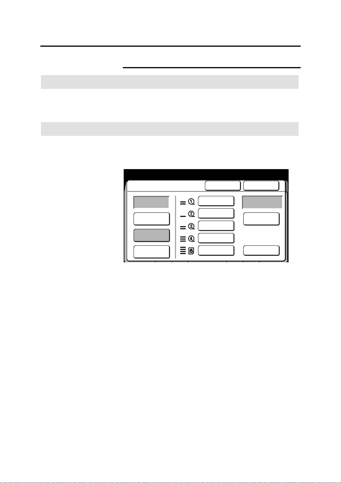
R/E; media; cut (continued)
y
01
R/E by L&W
Introduction
The R/E by L&W feature reduces or enlarges copies, from the
desired length and width percentages you enter. You can reduce or
enlarge the length and width of your copies, in ± 0.1% increments,
from 25 to 400%.
Procedure
1. Select the basic feature group tab. If needed, refer to page 68.
2. Select the R/E; media; cut button, on the basic screen.
The R/E; media; cut screen is displayed.
Ready to cop
Load documents face down
R/E; Media; Cut Cancel Done
Selected
100.0%
Normal R/E
R/E by L&W
100.0%
36” Bond
24” Bond
24” Bond
18” Vellum
12”x18” Bond
3. Select R/E by L&W.
The R/E by L&W screen is displayed.
Synchronized
Paper Length
Adjustment
Manual Feed
Basic touch screen features 73
Page 76
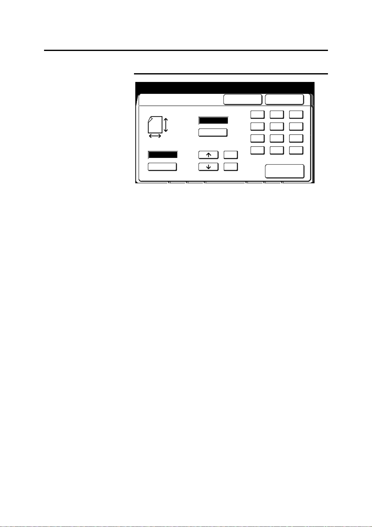
R/E; media; cut (continued)
y
01
X
X
%
%
R/E by L&W (continued)
Ready to cop
Load documents face down
R/E by L&W
25.0% – 400.0%
Y
25.0% – 400.0%
Cancel Done
123
Y
+0.1
−0.1
456
789
•
Selected
0C
R/E
Auto Calc
Use the touch screen keypad to enter data and select the C
button to clear wrong data.
4. Select X and enter the desired width percent.
5. Select Y and enter the desired length percent.
To cancel the changes and exit from this screen, select cancel.
6. Insert the document to make copies, or select done as required
to select more features.
74 Basic touch screen features
Page 77

R/E; media; cut (continued)
y
01
y
01
Normal R/E calculator
Introduction
The normal R/E calculator feature calculates the copy percentage
automatically based on the document length and the required copy
size length.
Procedure
1. Select the basic feature group tab. If needed, refer to page 68.
2. Select the R/E; media; cut button, on the basic screen.
The R/E; media; cut screen is displayed.
Ready to cop
Load documents face down
R/E; Media; Cut Cancel Done
Selected
100.0%
Normal R/E
R/E by L&W
100.0%
36” Bond
24” Bond
24” Bond
18” Vellum
12”x18” Bond
3. Select normal R/E.
The normal R/E screen is displayed.
Ready to cop
Load documents face down
200.0%
129.4%
100.0%
64.7%
50.0%
25.0%
Variable
25.0% - 400.0%
100.0
+0.1
−0.1
Synchronized
Paper Length
Adjustment
Manual Feed
Selected
Cancel DoneNormal R/E
123
456
789
%
•
0C
R/E
Auto Calc
4. Select R/E auto calc.
The R/E auto calculate screen is displayed.
Basic touch screen features 75
Page 78

R/E; media; cut (continued)
01
Normal R/E calculator (continued)
Enter document length from the numeric pad
Press [Scroll]
R/E Auto Calc
Required Copy Length
Reduce/Enlarge
100
%
Document Length
mm
mm
Cancel Done
123
456
789
Selected
0C
Scroll
Use the touch screen keypad to enter data and select the C
button to clear wrong data.
5. Enter the document length.
6. Select scroll and move to the required copy length field.
7. Enter the required copy length.
8. Select scroll.
The reduce/enlarge field displays the new percentage.
To cancel the changes and exit from this screen, select cancel.
9. Insert the document to make copies, or select done as required
to select additional features.
76 Basic touch screen features
Page 79

R/E; media; cut (continued)
y
01
X
X
y
01
R/E by L&W calculator
Introduction
The R/E by L&W calculator feature calculates the copy percentage
automatically based on the document length and width and the
required copy size length and width.
Procedure
1. Select the basic feature group tab. If needed, refer to page 68.
2. Select the R/E; media; cut button, on the basic screen.
The R/E; media; cut screen is displayed.
Ready to cop
Load documents face down
R/E; Media; Cut Cancel Done
Selected
100.0%
Normal R/E
R/E by L&W
100.0%
36” Bond
24” Bond
24” Bond
18” Vellum
12”x18” Bond
3. Select R/E by L&W.
The R/E by L&W screen is displayed.
Ready to cop
Load documents face down
R/E by L&W
25.0% – 400.0%
Y
Y
25.0% – 400.0%
%
+0.1
−0.1
Synchronized
Paper Length
Adjustment
Manual Feed
Cancel Done
%
123
456
789
•
0C
Auto Calc
Selected
R/E
4. Select R/E auto calc.
The R/E auto calculate (L& W) screen is displayed.
Basic touch screen features 77
Page 80

R/E; media; cut (continued)
01
%
%
R/E by L&W calculator (continued)
Enter document length (Ver) from numeric pad
Press [Scroll]
R/E Auto Calc (L&W)
Document Length Document Length
100 100
Reduce/Enlarge Reduce/Enlarge
mm
Required Copy Length Required Copy Length
mm
Cancel Done
mm
mm
123
456
789
Selected
0C
Scroll
Select scroll, to move to the desired fields.
Use the touch screen keypad to enter data and select the C
button to clear wrong data.
5. Enter the desired reduce/enlarge m eas urement.
6. Enter the required copy length.
7. Enter the desired reduce/enlarge m eas urement.
8. Enter the required copy length (width).
9. Select scroll.
• The calculated percentages are displayed in the document
length fields.
To cancel the changes and exit from this screen, select cancel.
10. Insert the document to make copies, or select the done as
required to select additional features.
78 Basic touch screen features
Page 81

R/E; media; cut (continued)
Paper length adjustment
Note: The paper length adjustment button is only available if roll
media is selected on the R/E; media; cut screen.
Introduction
Paper length adjustment feature provides four cut options for
manual mode; standard, synchronized, long copy and variable
length.
Option Function
Standard
Synchronized
Long copy
Variable
length
Cuts roll media to standard and special size lengths.
For detailed information about the standard sizes,
refer to page 56. MAX 200 nonstandard size is
30 x 42 inch.
Cuts roll media to the length of the original up to
19.8 feet (6 m). Refer to page 81.
For detailed information on how to set the custom
presets default for the lead and trail edge margins
for synchronized, refer to page 216.
Cuts roll media for to the length of original, when the
original is greater than 19.8 feet (6m), refer to
page 83.
For detailed information on how to set the custom
presets default for the lead and trail edge margins
for long copy, refer to page 216.
Operator specifies the media cut length. Refer to
page 85.
For detailed information on how to set the custom
presets default for each roll, refer to page 218.
Basic touch screen features 79
Page 82

R/E; media; cut (continued)
y
01
y
01
Paper length adjustment (continued)
Procedure
1. Select the basic feature group tab. If needed, refer to page 68.
2. Select the R/E; media; cut button, on the basic screen.
The R/E; media; cut screen is displayed.
Ready to cop
Load documents face down
R/E; Media; Cut Cancel Done
Standard
Selected
100.0%
Normal R/E
R/E by L&W
100.0%
36” Bond
24” Bond
24” Bond
18” Vellum
12”x18” Bond
3. Select paper length adjustment.
The paper length adjustment screen is displayed.
Ready to cop
Load documents face down
Paper Length Adjustment
Standard
Synchronized
Long Copy
Variable
Length
Landscape Portrait
Cancel Done
Document Direction
Synchronized
Paper Length
Adjustment
Manual Feed
Selected
4. Select standard.
80 Basic touch screen features
Page 83

R/E; media; cut (continued)
y
01
Paper length adjustment (continued)
Standard (continued)
Ready to cop
Load documents face down
Paper Length Adjustment
Standard
Synchronized
Long Copy
Variable
Length
Cancel Done
Document Direction
Landscape Portrait
Selected
5. Select the desired document direction, landscape or portrait.
• For example: When A0 width roll media is selected, choose:
Portrait to make A0-size copies.
Landscape to make A1-size copies.
To cancel the changes and exit from this screen, select cancel.
6. Insert the document to make copies, or select done as required
to select additional features.
Synchronized
Procedure
Note: The synchronized option can be selected with magnification.
The width of document does not have to be the same as the media
width.
1. Select the basic feature group tab. If needed, refer to page 68.
2. Select the R/E; media; cut button, on the basic screen.
The R/E; media; cut screen is displayed.
Basic touch screen features 81
Page 84

R/E; media; cut (continued)
y
01
y
01
Paper length adjustment (continued)
Synchronized (continued)
Ready to cop
Load documents face down
R/E; Media; Cut Cancel Done
100.0%
Normal R/E
R/E by L&W
100.0%
36” Bond
24” Bond
24” Bond
18” Vellum
12”x18” Bond
Synchronized
Paper Length
Adjustment
Manual Feed
3. Select paper length adjustment.
The paper length adjustment screen is displayed.
Ready to cop
Load documents face down
Paper Length Adjustment
Standard
Synchronized
Cancel Done
Document Direction
Selected
Selected
Long Copy
Variable
Length
Landscape Portrait
4. Select synchronized.
The second paper length adjustment screen is displaye d.
82 Basic touch screen features
Page 85

R/E; media; cut (continued)
01
y
y
01
Paper length adjustment (continued)
Synchronized (continued)
Ready to cop
Load documents face down
Paper Length Adjustment
Standard
Synchronized
Long Copy
Variable
Length
Cancel Done
Selected
mm (-90~+999)
0
+100
−100
mm (-90~+999)
0
+100
−100
Clear
Clear
5. Adjust the margins as desired, using the arrow or the ±±±± 100
buttons. To clear wrong data, select clear.
• You can add up to 999 mm to the lead or trail edge margin
or remove up to 90 mm from the lead or trail edge margin.
To cancel the changes and exit from this screen, select cancel.
6. Insert the document to make copies, or select done as required
to select additional features.
Long copy
Procedure
1. Select the basic feature group tab. If needed, refer to page 68.
2. Select the R/E; media; cut button, on the basic screen.
The R/E; media; cut screen is displayed.
Ready to cop
Load documents face down
R/E; Media; Cut Cancel Done
100.0%
Normal R/E
R/E by L&W
100.0%
36” Bond
24” Bond
24” Bond
18” Vellum
12”x18” Bond
Selected
Synchronized
Paper Length
Adjustment
Manual Feed
3. Select paper length adjustment.
The paper length adjustment screen is displayed.
Basic touch screen features 83
Page 86

R/E; media; cut (continued)
y
01
01
y
Paper length adjustment (continued)
Long copy (continued)
Ready to cop
Load documents face down
Paper Length Adjustment
Standard
Synchronized
Long Copy
Variable
Length
Cancel Done
Document Direction
Landscape Portrait
Selected
4. Select long copy.
The second paper length adjustment screen is displayed.
Ready to cop
Load documents face down
Paper Length Adjustment
Standard
Synchronized
Cancel Done
Selected
mm (-90~+999)
0
+100
−100
Clear
mm (-90~+999)
Long Copy
Variable
Length
0
+100
Clear
−100
5. Adjust the margins as desired, using the arrow or the ±±±± 100
buttons. To clear wrong data, select clear.
• You can add up to 999 mm to the lead or trail edge margin
or remove up to 90 mm from the lead or trail edge margin.
To cancel the changes and exit from this screen, select cancel.
6. Insert the document to make copies, or select done as required
to select additional features.
84 Basic touch screen features
Page 87

R/E; media; cut (continued)
y
01
y
01
Paper length adjustment (continued)
Procedure
1. Select the basic feature group tab. If needed, refer to page 68.
2. Select the R/E; media; cut button, on the basic screen.
The R/E; media; cut screen is displayed.
Ready to cop
Load documents face down
R/E; Media; Cut Cancel Done
Variable length
Selected
100.0%
Normal R/E
R/E by L&W
100.0%
36” Bond
24” Bond
24” Bond
18” Vellum
12”x18” Bond
3. Select paper length adjustment.
The paper length adjustment screen is displayed.
Ready to cop
Load documents face down
Paper Length Adjustment
Standard
Synchronized
Long Copy
Variable
Length
Landscape Portrait
Cancel Done
Document Direction
Synchronized
Paper Length
Adjustment
Manual Feed
Selected
4. Select variable length.
The second paper length adjustment screen is displaye d.
Basic touch screen features 85
Page 88

R/E; media; cut (continued)
y
01
Paper length adjustment (continued)
Variable length (continued)
Ready to cop
Load documents face down
Paper Length Adjustment
Standard
Synchronized
Long Copy
Variable
Length
Cancel Done
(210 – 4161)
123
456
789
Selected
mm
0C
5. Set the length of the copy (210 – 4161 mm), using the touch
screen keypad and select the C button to clear wrong data.
To cancel the changes and exit from this screen, select cancel.
6. Insert the document to make copies, or select done as required
to select additional features.
86 Basic touch screen features
Page 89

Image density
y
01
Introduction
Procedure
The image density feature allows you to make adjustments to the
colors red and black on your copies. Each color can be adjusted
separately. Typically if the original is very light, you will want to
change the density too darker.
1. Select the basic feature group tab. If needed, refer to page 68.
2. Select the image density button, on the basic screen.
The image density screen is displayed.
Ready to cop
Load documents face down
Image Density
Cancel Done
Selected
Black Red
Normal Normal
Lighter
Darker
3. Adjust the black and red density levels to meet your specific
needs.
To increase density, select the down arrow. To decrease
density, select the up arrow. To return to normal, select the
normal button.
To cancel the changes and exit from this screen, select cancel.
4. Insert the document to make copies, or select done as required
to select additional features.
Basic touch screen features 87
Page 90

Document image type
y
Introduction
The document image type screen contains two features, document
image type and background suppression.
To ensure excellent copy quality, it is good practice to select the best
document image type that matches your document.
You can also suppress any unwanted background on your document
with the background suppression feature.
Feature Function
Procedure
Document image type
There are six document type options, line,
picture, line/picture, photo, low contrast
and dark. The machines image quality
components are automatically calibrated to
ensure proper copy quality
Background
suppression
The background suppression feature
allows you to suppress unwanted
background on documents. There are two
background suppression options; fixed and
variable.
1. Select the basic feature group tab. If needed, refer to page 68.
2. Select the document image type button, on the basic screen.
The document image type screen is displayed.
Ready to Cop
Load documents face down
Document Image Type
Line Line/Picture
Cancel Done
Background
Suppression
Fixed
Selected 01
Max
Picture Photo
Low Contrast Dark Off
Variable
Min
88 Basic touch screen features
Page 91
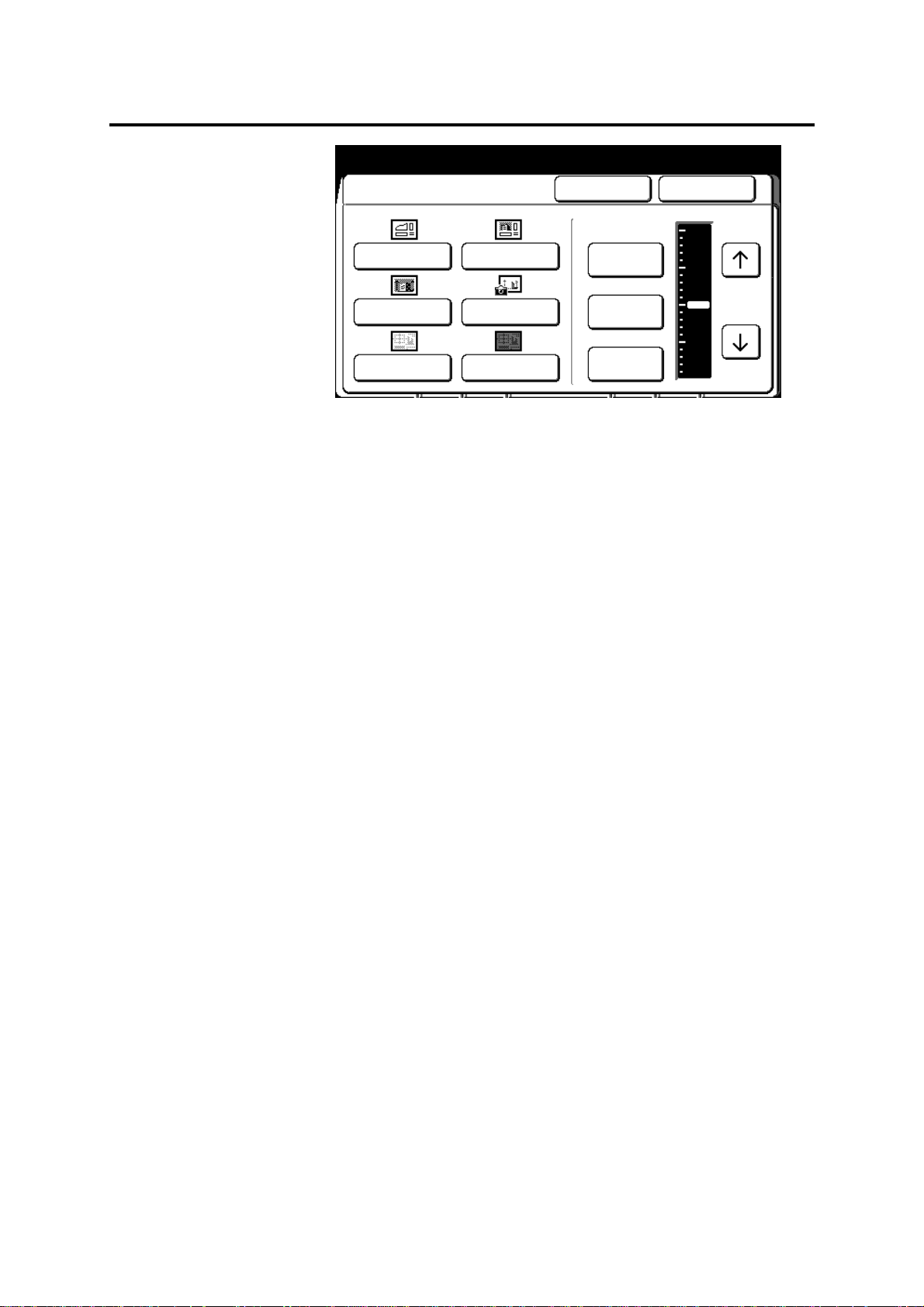
Document image type (continued)
y
Ready to Cop
Load documents face down
Document Image Type
Line Line/Picture
Picture Photo
Low Contrast Dark Contrast Off
Cancel Done
Background
Suppression
Fixed
Variable
Selected 01
Max
Min
3. Select the document image type that best matches your
document.
Line
Select when the original contains lines and text
images.
Picture
Select when the original contains dot matrix
images (like newspaper, posters, or copy of
photographs).
Line/picture
Select when the original contains text/lines and
dot matrix images or halftone images.
Photo
Select when the original contains pure glossy
image.
Low contrast
Dark contrast
Select when the original contains pencil writing.
Select when the original contains a dark
background (negatives, blueprints, sepias,
diazo).
4. Select the desired background suppression. If needed, select
the arrow buttons to further adjust the background suppression
level.
Fixed
Select fixed when the background is unif orm.
Examples include diazo paper , ne wspa per, and
colored paper.
Variable
Select variable when the background is not
uniform. For example the document
background has light and dark areas .
Off
Background suppress feature is off.
To cancel the changes and exit from this screen, select cancel.
5. Insert the document to make copies, or select done as required
to select additional features.
Basic touch screen features 89
Page 92

Print color
y
01
Color
Introduction
The print color feature allows you to select a specific color for print.
There are three options available.
Option Function
Procedure
Red only
Prints all in red. Refer to the one color
procedure, on page 90.
Black only
Prints all in black. Refer to the one color
procedure, on page 90.
Red/black
Prints in red and black. Operator specifics the
colors the machine recognizes to be printed in
red. Refer to the two color procedure, on page
91.
One color (black or red)
1. Select the basic feature group tab. If needed, refer to page 68.
2. Select the print color button, on the basic screen.
The print color screen is displayed.
Ready to cop
Load documents face down
Print Color
Cancel Done
Selected
Printed as Red
Black/Red
Printed All in
Black
Red Only
Black Only
Scanned
3. Select black only or red only.
To cancel the changes and exit from this screen, select cancel.
4. Insert the document to make copies, or select done as required
to select additional features.
90 Basic touch screen features
Page 93

Print color (continued)
y
01
A
y
01
Color
Two color (black and red)
Note: This option is automatically enabled, if you set any of the copy
features to recognize a specific color on your document to be printed
red.
Procedure
1. Select the basic feature group tab. If needed, refer to page 68.
2. Select the print color button, on the basic screen.
The print color screen is displayed.
Ready to cop
Load documents face down
Print Color
Selected
Cancel Done
Printed as Red
Black/Red
Red Only
Black Only
Printed All in
Black and Red
Press [Scanned
Color] to select
document color(s)
to be printed in red.
Red
Scanned
3. Select black/red.
4. Select scanner color (specifies the color on the document to be
printed in red).
The scanned color screen is displayed.
Ready to cop
Load documents face down
Scanned Color
One or more colors in the original document
may be copied in red
ll others will be copied in black
Red
Cancel Done
Green
Selected
Others
Blue
Yellow
Black
5. Select the desired colors, to be copied in red. To cancel a color
selection, press the same color button again.
• Multiply colors can be selected.
• Others specify colors other than red, blue, green, yellow,
and black.
To cancel the changes and exit from this screen, select cancel.
6. Insert the document to make copies, or select done as required
to select additional features.
Basic touch screen features 91
Page 94

Image quality touch screen features
y
01
The image quality touch features allow you to adjust the copy
quality.
Procedure
Ready to cop
Load documents face down
Basic
Sharpness
Image Quality Additional Finishing
Scan Color
Sensitivity
Selected
Procedure to access the image quality feature group screen:
1. Select the image quality feature group tab.
The image quality feature group screen is displayed.
2. Go to the desired selection.
• Sharpness, page 93.
• Scan colo r sensit iv ity, page 94.
92 Image quality touch screen features
Page 95

Sharpness
y
01
Introduction
The sharpness feature adjusts the image edge sharpness of the
copy. There are three options; maximum, normal and minimum.
Option Function
Procedure
Maximum
Normal
Minimum
Select to achieve maximum sharpness.
Select to achieve normal sharpness.
Select to achieve minimum sharpness.
1. Select the image quality feature group tab. If needed, refer to
page 92.
2. Select the sharpness button, on the image quality screen.
The sharpness screen is displayed.
Ready to cop
Load documents face down
Sharpness Cancel Done
Maximum
Normal
Selected
Minimum
3. Select the desired sharpness; maximum, normal or minimum.
To cancel the changes and exit from this screen, select cancel.
4. Insert the document to make copies, or select done as required
to select additional features.
Image quality touch screen features 93
Page 96

Scan color sensitivity
y
01
Introduction
The scan color sensitivity feature increases or decreases the
density for each selected color, on the copy.
For example, the map you want to copy has areas in blue that you
want to appear darker on the copy. Select dark blue on the scanner
color sensitivity screen. The blue areas on your copies are printed
darker.
Procedure
1. Select the image quality feature group tab. If needed, refer to
2. Select the scanner sensitivity button, on the basic screen.
Ready to cop
Load documents face down
Scan Color Sensitivity Cancel Done
page 92.
The scanner sensitivity screen is displa yed.
Selected
Yellow
Others BlackColor
Light
Normal
Dark
Red Blue Green
Maximum
3. Select an arrow button to adjust desired color.
• Others specify colors other than red, blue, green, yellow,
and black.
To cancel the changes and exit from this screen, select cancel.
4. Insert the document to make copies, or select done as required
to select additional features.
94 Image quality touch screen features
Page 97

Additional touch screen features
y
01
The additional features allow you to change the image location or
edit your document.
Procedure
Ready to cop
Load documents face down
Basic
Off Off
Image
Location
Image Quality Additional Finishing
Editing
Selected
Note: The text above each selection button provides the status of
each feature.
Procedure to access the additional feature group screen:
1. Select the additional feature group tab.
The additional feature group screen is displayed.
2. Go to the desired selection.
• Image location, page 96.
• Editing, page 97.
Additional touch screen features 95
Page 98
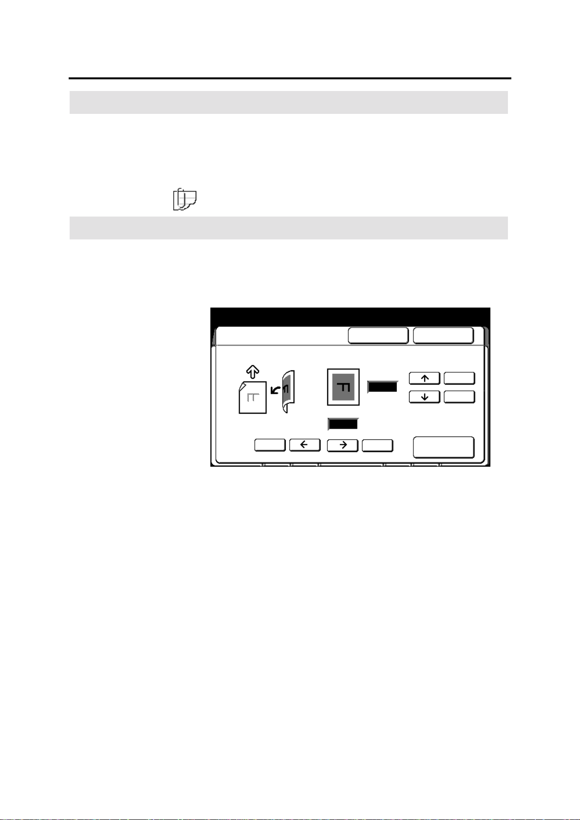
Image location
y
01
Introduction
Procedure
The image location feature shifts the image up, down or to the right
in 1-mm increments up to 30 mm.
The image cannot be shifted to the left (the left arrow button is
always disabled). If you copy requires a left margin, shift the image
to the right.
Note: If needed, you can shift your original to the left by moving the
document guides, on the scanner.
1. Select the additional feature group tab. If needed, refer to page
95.
2. Select the image location button, on the basic screen.
The image location screen is displayed.
Ready to cop
Load documents face down
Image Location Cancel Done
Selected
Doc. direction
(0~999)
0
(0~999)
mm
mm
0
100100
100
100
Clear
3. Select the top or bottom arrow buttons to shift the image up or
down. If needed, select the 100 buttons to shift the image in
100 increments.
4. Select the right arrow button to shift the image to the right. If
needed, select the 100 button to shift the image in 100
increments.
Select clear to set the values to 0.
To cancel the changes and exit from this screen, select cancel.
5. Insert the document to make copies, or select done as required
to select additional features.
96 Additional touch screen features
Page 99

Editing
y
01
Introduction
The MAX 200 provides two edit configurations; basic and full. When
the optional editing kit is installed, your machine is equipped with the
full configuration.
• If your machine is not equipped with the editing kit, the MAX 200
allows access to the basic edit features only. All basic edit
features are identified with the word basic next to the feature.
• If your machine is equipped with the optional edit kit, the
MAX 200 allows access to all edit features.
The screen below, is the editing screen. It is displayed when you
select the editing button, on the additional feature group tab.
Ready to cop
Load documents face down
Editing Cancel Done
Area Editing
Entire
Document
Area Identified by
marker or coordinates
Selected
Off
Over All
Editing
Feature Function
Overall editing
Allows you to edit the entire document. Refer to
page 98.
Marker editing
Allows you to specify the edit area, with a
marker. You can define multiple edit areas on
your document. Refer to page 107.
Coordinate
editing
Allows you to specify a single edit area with, X
and Y coordinates on your document. Refer to
page 119.
Marker
Editing
Coordinates
Editing
Additional touch screen features 97
Page 100

Editing (continued)
y
01
Introduction
Overall editing
The overall edit feature allows you to edit the entire document.
There are four overall edit options; fill, contrast reversal, mirror
image, and color drop.
Option Function
Procedure
Fill
Lets you cover an entire document, or edit areas
with a pattern. There are seven fill patterns and
three levels of fill available. The fill is in black or
red.
Contrast reversal
(basic)
Prints black (or red) images on a document to be
printed white and white areas to be printed in black
(or red). It is useful when converting old blueprints
or negatives.
Mirror image
Color drop
Prints as the reflection of the original document.
Allows you to delete select colors from the copy.
(basic)
1. Select the additional feature group tab. If needed, refer to page
95.
2. Select the editing button, on the basic screen.
The editing screen is displayed.
Ready to cop
Load documents face down
Editing Cancel Done
Selected
Off
Entire
Document
Over All
Editing
Area Editing
Area Identified by
marker or coordinates
Marker
Editing
Coordinates
Editing
3. Select overall editing.
The overall screen is displayed.
98 Additional touch screen features
 Loading...