

Page 1
User Manual – IGEN Coupler Board
1.0 System Components
There are two components, not including the driving host computer and the power
supply, of the Radio Frequency CRUM Sub-System; the IGEN Coupler board (PWBA)
and the RF memory tag (TAG). The PWBA is controlled by a host computer which sends
commands and data to the PWBA. The PWBA then converts the commands into radio
frequency actions which allow communication to the TAG.
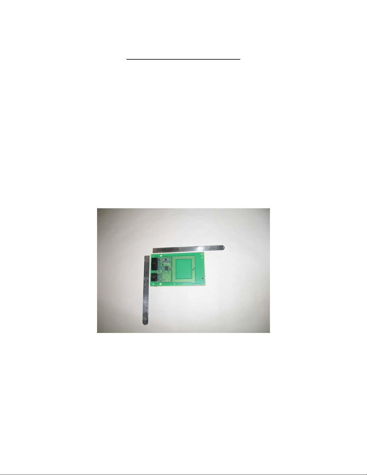
1.1 IGEN Coupler Board
The photo below shows the PWBA. The two connectors on the left side of the board are
used for power input, addressing and communication.
1
Page 2
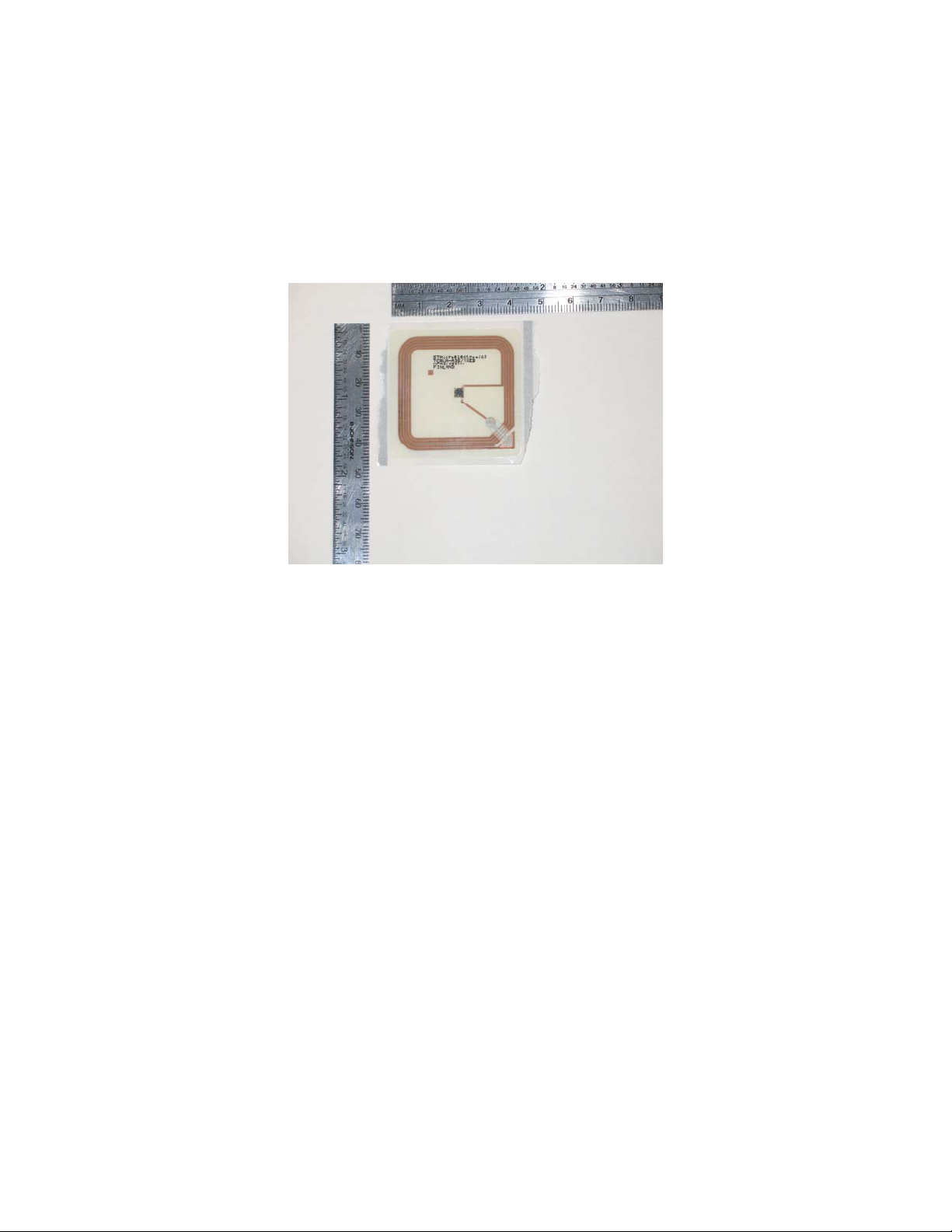
1.2 RF Memory Tag (TAG)
The TAG is a memory device which is mounted on a flexable substrate. The memory
device is surrounded by a copper antenna also on the substrate. Through this antenna,
power for the memory device and it’s associated controlling hardware is obtained from
the RF signal generated by the PWBA.
2.0 Applying power to the PWBA (refer to the schematic for this discussion).
Power is applied to the PWBA through the 6 pin connector (5volts DC) or the 10 pin
connector (7.5 volts DC).
The 6 pin connector receives 5 volts on pin 1 (5volts) and pin 3 (ground).
The 10 pin connector receives 7.5 volts on pins 9, 10 (7.5 volts) and pin 8 (ground).
Note that the board cannot operate from both supply voltages at one time.
3.0 Board Addressing
Up to 8 PWBA’s can be communicated to by the host computer by using the three
address lines (ADD_E0, ADD_E1 and ADD_E2). These address lines are tied into the 6
pin and the 10 pin interface connectors. If the addressing lines are left open, address 0
will be selected. External address jumpers select the remaining addresses in a binary
fashion (refer to the schematic for details).
4.0 Sample Communication Protocol, IGEN Coupler Board to RF Memory Tag
(Note: The details of the communication protocol are beyond the scope of this document.
This is just a high level overview).
The host processor board switches power on to the PWBA’s.
A 100 milli-second stabilization time is waited.
The RF field ON command is sent from the host processor to the PWBA to be
communicated to.
2
Page 3

The “find memory tag” command is sent from the host processor to the PWBA.
The addressed PWBA generates an RF signal to find a TAG which could be in
it’s field.
After a TAG is found, a “select memory tag” command is sent from the host
processor to the PWBA. Note that the PWBA converts the command into an RF
signal for the TAG.
Using a custom protocol, the host processor, the PWBA and the TAG transfer
data blocks as required.
The RF field OFF command is sent from the host processor to the PWBA.
The host processor board removes power from the PWBA’s to end
communication.
5.0 IGEN Coupler Board and RF Memory Tag Operation within a Xerox Printer
The following illustrates one application for the IGEN Coupler board and RF Memory
Tag as it would be used within a printing system.
5.1 RF Memory Tag Intallation on a Toner Bottle
The photo below shows the RF memory tag mounted on a toner bottle. Note that
unlike this photo, after the memory tag is mounted on the bottle cap, a protective
label will be placed over the memory tag (not shown).
Toner Bottle
RF Memory
Tag
3
Page 4

5.2 RF Coupler Boards Mounted in a machine.
The photo below shows 4 PWBA’s mounted in a machine. The memory tags
associated with each PWBA are mounted on toner bottles behind the boards (cannot
be seen in this photo).
RF Coupler
Board
Toner Bottles
behind these
doors
4
Page 5

5.3 Printer that houses the RF Coupler Boards and RF Memory Tags
The RF Coupler Boards are located behind this door in the machine.
5
Page 6

REGULATORY INFORMATION
FCC PART 15 COMPLIANCE
THIS DEVICE COMPLIES WITH PART 15 OF THE FCC RULES. OPERATION IS
SUBJECT TO THE FOLLOWING TWO CONDITIONS: (1) THIS DEVICE MAY
NOT CAUSE HARMFUL INTERFERENCE, AND (2) THIS DEVICE MUST ACCEPT
ANY INTERFERENCE RECEIVED, INCLUDING INTERFERENCE THAT MAY
CAUSE UNDESIRED OPERATION.
MODIFICATIONS TO THE EQUIPMENT NOT EXPRESSLY APPROVED BY
XEROX COULD VOID THE USER’S AUTHORITY TO OPERATE THE
EQUIPMENT.
ANY HOST DEVICE THAT CONTAINS THIS MODULE IS REQUIRED TO
CLEARLY STATE THE FOLLOWING ON THE OUTSIDE OF THE HOST DEVICE:
“CONTAINS FCC ID: LD7IGEN”.
Marty Oksenhorn
XEROX CORPORATION
12/10/07
6
 Loading...