

Page 1

XEROX
82332
Rev. G
Diablo Systems Incorporated
A Xerox Company
HyTerm
Communications
Model
Product
1610/1620
Description
Terminal
December,
1978
Page 2

©
Copyright
Diablo Systems, I
Hayward,
All
rights reserved
1976,1977,1978
California
nco
(A
Xerox
94545
Company)
"Diablo,"
"HyTerm"
"HyType,"
is
a trademark
and
"Xerox"
of
Diablo Systems, Inc.
are registered trademarks
of
Xerox
Corporation.
Page 3

This
manual
interface,
1620
HyTerm
This
revision
the
information
8-20-76,
issued
Addendum
Comments
use
Diablo
ments
incorporate
delivered.
subject
on
the
to
Addendum
Reader
Systems,
to
provides
and
install
Communications
supercedes
contained
9-30-77,
F2,
on
products
Features
change
issued
this
Comment
I nc., reserves
such
improvements
without
Addendum
manual
and
PREFACE
the
information
the
Diablo
all
previous
C1,
issued
on
4-25-78.
and
Form
without
specifications
notice.
Terminals.
in
Addendum
on
F 1, issued
its use
in
the
incurring
in
necessary
Model
revisions,
5-26-77,
are
the
back
right
to
any
units
previously
described
to
1610
and
and
A 1, issued
Addendum
on
4-15-78,
welcome.
of
this
make
obligation
herein
operate,
Model
includes
on
D1,
and
Please
manual.
improve-
sold
are
to
or
HOW
This
manual
will
need
provides
read
by
terminal.
meant
provides
of
the
computer
Section 4 contains
anyone
terminal.
designed
desiring
should
Publication
is
made
to
read
a basic i.-.troduction
anyone
Section 2 contains
primarily
more
information
terminal,
programmer
planning
for
technical
refer
to
Section 5 contains
the
installer
to
the
No.
82333.
TO
USE
THIS
up
of
five
sections.
the
entire
manual.
to
the
needing
for
and
connect a modem
information
Model
the
is
written
or
detailed
and
1610/1620
more
operating
machine
on
the
network
interface
installation
the
on
MANUAL
The
HyTerm,
information
instructions,
operator.
functional
primarily
designer
data,
or
other
installation
servicing
Maintenance
Not
every
first
and
should
about
Section
characteristics
with
the
in
needed
device
procedures;
planner.
the
terminal
Manual,
reader
section
be
the
and
host
mind.
by
to
the
it
Those
is
3
is
Page 4

The
Diablo
Communications
materials
shipment.
should
All
repair
possible service.
and
be
directed
requests
depot
Any
for
in
WARRANTY
Model
workmanship
Terminals
questions
to
your
repairs
your
area.
1610
should
and
are
for
with
Diablo
This
Model
warranted
90
days
respect
sales
representative.
be
directed
will assure
1620
against
from
to
the
to
you
of
HyTerm
defects
the
date
warranty
the
the
in
of
Diablo
fastest
ii
Page 5

TABLE
OF
CONTENTS
PARAGRAPH
SECTION' -GENERAL
1.1
Introduction
1.2 Main
1.3
1.4
1.5
1.6
1.7 Related
Features.
1.2.1
1.2.2
1.2.3
1.2.4
Specifications.
1.3.1
1.3.2
1.3.3
1.3.4
1.3.5
1.3.6
1.3.7
Functional
1.4.1
1.4.2
1.4.3
Optional
Accessories.
.
Printer
Switch
Keyboard.
Commun
Size...
Weight..
Power
Environ mental
Printer.
Interface
Color..
Features.
Control
Escape Sequences
Control
Features
. .
Documents
DESCRIPTION
Panels
ications Capability
Requirements
Requirements.
Codes.
Panel
and
Front
Panel
Switches
PAGE
'·1
1·1
1·1
1·1
'·2
1·2
1·2
1·2
1·2
1·2
1·2
1·2
1·3
1·3
1·3
1·3
1·3
1·4
1·4
1·4
1-5
SECTION 2 - OPERATING INSTRUCTIONS
2.1
Introduction
2.2
Switches, Indicators,
2.2.1
2.2.2
2.2.3
2.2.4
2.2.5
2.2.6
2.2.7
Operating
Basic
2.3
2.3.1
2.3.2
2.3.3
. . .
and
Controls
Front
Panel
Control Pane
Keyboard
2:2.3.1
2.2.3.2
2.2.3.3
Printer
I mpression
Cover-Open Switch
Paper-Out-Switch
Turn-On..
Loading
2.3.2.1
2.3.2.2
Establishing
2.3.3.1 Originating a Data Link
2.3.3.2
2.3.3.3
2.3.3.4
I.
.
.
Alphameric
Numeric
Control Section .
Controls
Control
Procedures
Paper.
Top-Feed
Bottom-Feed
the
Originating a Data Link
Originate-Only Modems
Answering a Data Link Call
Section
Section
.
Switch
.
Printer.
Printer
Data
Communications
Link.
with
an
Acoustic
with
a Bell-Type Modem
Coupler
2·1
2·1
2·1
2·1
2·5
2·5
2·5
2·7
2·7
2·8
2·8
2-9
2·9
2·9
2·9
2·9
2·10
2·11
2·11
2·12
2-12
2·12
iii
Page 6

SECTION 2 -
OPERATING
INSTRUCTIONS
(Continued)
2.3.4
Error Recovery
2.3.5 Keyboard Control
2.3.5.1 Margins
2.3.5.2 Carriage Movement
2.3.5.3
Paper Movement
2.3.5.4 Ribbon Control .
2.4
Operator Duties . . . . . . .
2.4.1 Replacing Ribbon Cartridge
2.4.2 Changing Printwheels
2.4.3
Changing
2.4.3.1
Platens.
Platen Removal .
2.4.3.2 Standard Platen (Friction-Feed) Installation
2.4.3.3 Pin-Feed Platen Installation
2.4.4
SECTION 3 -
3.1
Introduction
Forms
Tractor
FUNCTIONAL
. .
3.1.1 Local/Remote
3.2 Communications Princi
3.3 Reset/In itialization . . .
3.4 Character Generation
3.4.1 Two- and Three-Character Sequences
Printing Format . . . .
3.5
3.5.1
Definition
of
3.5.2 Standard Formats
3.5.3 Optional Formats (Variable Indexing)
3.5.3.1 Variable
3.5.3.2 Variable
Control Functions
3.6
3.6.1 Control
of
3.6.1.1 Red/Black
3.6.1.2 Upper
3.6.2
Control
3.6.2.1
of
Space
3.6.2.2 Backspace
3.6.2.3 Carriage Return (CR)
3.6.2.4 Horizontal Tabbing (HT,
3.6.2.5 Graphics (ESC
3.6.2.6 Forward/Backward
3.6.2.7 Margins (ESC 9,
3.6.3 Control
of
3.6.3.1 Line
3.6.3.2
Form
3.6.3.3 Graphics
3.6.3.4 Vertical Tabbing
3.6.4
Other
Control Functions . . . .
....
of
Features. .
(ESC
9,
ESC
0)
. . .
DESCRIPTION
..
pies
Terms.
. . .
HMI
VMI
Printing .
Printing (ESC
Case
On
Iy.
.
A/ESC
B)
.
Carriage Movement
(SP).
. .
(8S)
ESC
1,
ESC
2,
3,
ESC
4) . .
Print (ESC 5/ESC
ESC
0) . . . . .
Platen (Paper) Movement . . . .
Feeds
(LF,
ESC
LF,
ESC
U,
ESC
Feed
(FF)
. . . .
(ESC
3,
ESC
4) .
(ESC
VT)
6)
D)
ESC
HT)
2-12
2-13
2-14
2-14
2-14
2-14
2-15
2-15
2-17
2-19
2-20
2-20
2-21
2-21
3-1
3-1
3-1
3-1
3-1
3-1
3-3
3-3
3-3
3-3
3-4
3-4
3-4
3-4
3-4
3-4
3-5
3-5
3-5
3-5
3-5
3-6
3-6
3-7
3-7
3-7
3-7
3-7
3-7
3-8
iv
Page 7

SECTION 3 -
FUNCTIONAL
DESCRIPTION (Continued)
3.7
Motion
SECTION 4 -
4.1
Introduction
4.2
Modem
4.3
Functional
4.4
Connection
Minimization
INTERFACE
4.5 Signal Levels .
4.6
I
nterface
4.7 Data
4.8
4.9
4.10
SECTION 5 -
5.1
5.2
5.3
Format
Timing
Circuit
Elements
4.9.1
4.9.2
Current -Loop
INSTALLATION
Introduction
Preliminary
Unpacking
5.4 System
5.4.1
5.4.2
5.4.3
5.4.4
5.5
Installation
5.5.1
5.5.2
5.5.3
5.6
Repackaging
3.6.4.1 Sound
Audible
3.6.4.2 Preventing
. .
Compatibility
Description.
to
the
Modem.
Signal s
.
. .
Input
Level
Converter
Output
Requirements
Operating
Space Requ irements .
Weight
Power
Initial
Jumper
5.5.2.1 1200
5.5.2.2
EIA
Level
Converter
Interface
.
Inspection
and
Inspection.
.
Environment.
. .
Requirements
Procedures.
Start-up
Cable Assembly
for
and
Installation/Removal.
Baud.
Ground
Shi
pment
Di sconnect .
Alarm
Buffer
Overrun
Checkout.
Connection
(BEL)
and
.
(ACK,
Remote
ETX,
Checkout.
NUL,
DEL)
3-8
3-8
3-8
4-1
4-1
4-1
4-3
4-3
4-3
4-4
4-5
4-5
4-5
4-6
4-6
5-1
5·1
5·1
5-1
5-1
5-1
5-1
5-1
5-1
5-3
5-3
5-3
5-5
5-5
5-5
Appendix
Appendix
A B -
ASCII
Code Chart
Keyboard
Layouts
and Code Charts
A-1
B-O
v
Page 8

LIST
OF
ILLUSTRATIONS
FIGURE
1-1
2-1
2-2
2-3
2-4
2-5
2-6
2-6a
2-7
2-8
2-9
2-10
2-11
2-12
2-13
2-13a
2-14
2-15
2-16
2-17
2-18
2-19
2-20
3-1
4-1
4-2
4-3
4-4
4-5
4-6
4-7
5-1
5-2
5-3
5-4
HyTerm
Switches,
Front
Control
46-Key
Printer
Cover-Open
Paper-Out
Ribbon
Ribbon
Ribbon
Carriage
Printwheel
Printwheel
Platen
Platen
Pin-Feed
Plastic Clip
Forms
Forms
Forms
Forms
Forms
Printing
Interface
Interface
Input
Data
Input
Output
Current
Top
HPRO
Jumper
Current
Communications
Indicators,
Panel 2-1
Panel .
Typewriter
Controls
and I mpression
Switch
Clamps
Advance
Cartridge
Tilted
Skirt
Removal
Platen
Tractor
Tractor
Tractor
Tractor
Tractor
Format
Functional
Connector.
Line
Format
Converter
Converter
Loop
Cover
Board
Location
Loop
Clip
Knob
Placement
for
Printwheel
Installation
.
Removal
Installation
and
Stud
and
and
and
Installed
Factors
Switching
on
Interface
IC
IC
Cable
Release Lever
Location
Connections
Terminal
and
Controls
Pairing
Keyboard
Control
Access
Platen
Adjust
Paper
Release Lever
Paper
Release Lever
Block Diagram
Levels
Pinout
.
Switches
Lever
(Tension
(Tension
Removed)
Removed)
PAGE
1-0
2-0
2-3
2-4
2-6
2-8
2-9
2-15
2-16
2-16
2-17
2-18
2-18
2-19
2-19
2-20
2-21
2-22
2-22
2-23
2-23
2-24
3-2
4-1
4-2
4-3
4-4
4-5
4-6
4-6
5-2
5-2
5-4
5-6
vi
Page 9

LIST
OF
TABLES
TABLE
2-1
2-2
2-3
3-1
3-2
3-3
4-1
4·2
4-3
5-1
Front
Panel
Switches
Control
Error
Standard
Deci mal Values
Control
I
nterface
Interface
Interface·
Jumper/Shorting
Panel.
Recovery
Formats
Functions
Signals .
Signal
Data
and
Indicators
. .
for
ASCII
Character
. . . . .
Terminology.
Timing . . .
Plug
Location
PAGE
2-2
2-3
2-13
3-3
3-4
3-5
4-2
4-3
4-5
5-5
vii
Page 10

MODEL 1610
Figure 1-1. HyTerm Communications Terminal
MODEL 1620
1-0
Page 11

SECTION 1
GENERAL
DESCRIPTION
1.1
INTRODUCTION
Diablo
printers and microelectronics
communications
of
the smallest and
one
today.
from a distant
Standard RS-232-C interface. I n local
keyboard/printer
correspondence and
munications
of
applications: in
a
computer
time-sharing
etc.
The
microprocessor-driven electronics,
tive
provides
data
is
a receive-only (RO) version,
keyboard send/receive
contain
pletely
inherent
versatility, plus a
optional
meet the most demanding data processing situations.
Systems
terminal,
of
the
most
economical and versatile
The
HyTerm
device over a
can
terminal,
console
network,
HyTerm
yet
functional
communications
an
self-contained table
forms-handling
comprises a
exactly
speed and
the
integral
has
combined
most
convenient
transmits data
also
other
the
HyTerm
terminal-to-terminal
or
output
as
a console in a
package. The
amount
application.
(KSR)
power
adaptability,
full
complement
equipment,
the latest
to
produce the
Figure 1-1. The
terminals
communication
serve
as a document
secretarial
can
printer,
Diablo
supply,
contained
HyTerm's
of
capability
The
while
capability.
top
unit.
and
HyType
enable the
technology
HyTerm
built,
units
to
and receives data
link
via
operation,
writer
functions.
function
communications,
as a terminal
text-editing
HyTerm
the Model
making
The
the
of
As a com-
in a
II
printer
in
an
modular
needed
Model
Both
them
HyType
microprocessor's
type
styles and
HyTerm
HyTerm
is
one
yet
it
available
an
EIA
the
for
variety
in a
system,
and
attracdesign
in
any
1610
1620
has
models
a com-
II's
in
as
to
difficult-to-modify,
logic. This makes several
"free,"
nothing"
complete
is
maintained
external commands can take advantage
graphics
tabbing, its non-left-margin returns, and its backward
printing
which
even
flexibility
in
capability,
capability.
space consuming,
can
be
used when desired,
if
they
are
of
the
interface design
its high-speed
functional
not
the
HyType
utilized.
so
horizontal
hard-wired
features available
but
In
" mechanism
that
of
random
which
addition,
appropriate
the
HyType's
and vertical
"cost
the
is
1.2.1 Printer
The
HyType
serviceability,
complemented
remarkable
parts, the
modularity
factors. Interchangeable daisy-wheel
printing
characters per inch. Rapid carriage and paper
provide high-speed
HyType
characters per second (cps), even
at
graphics capabil
and vertical resolution
in 1
the choice
only
/120"
of
II
10
II's
innate qualities - its speed,
reliability,
by
the microprocessor
printing
straightforward
of
95
is
to
increments
of
printing
system. The small
the plug-in
different
horizontal
capable
30
cps
ity
of
by
provides
is
format.
and excellent
control
mechanical design, and
circuit
boards
type
characters
printing
the
communications
horizontal
to
1
/48",
available
at
and vertical
at a nominal
though
resolution
but
horizontal
to
provide
print
quality
number
are
all
fonts
either
tabbing.
it
is
usually
wide
versatility,
- are
to
provide a
of
moving
the
contributing
provide
10
or
movement
The
speed
of
45
driven
link.
Normal
to
1/60"
movement
variety
12
in
1.2
MAIN
The
for I nformation
Code
ible
with
this
code.
of
all 94
to
5 copies.
up
113A
modems and
nous modems
tions
set
(EIA).
The
facets
electronic
plug
into
the design
microprocessor
reliability,
pre-programmed Read-Only
FEATURES
HyTerm
most
printable
HyTerm
of
communicates using the U.S.A. Standard
other
It
provides
It
employing
forth
by
represents
terminal
components
the
HyType " printer.
of
the
control
and speed.
I nterchange
data
medium
ASCII
is
compatible
many
the
design.
are
HyType
characters
other
the RS-232-C interface specifica-
Electron
to
Functional
(ASCII),
communications
speed,
high-quality
on
an
original
with
Bell
110-
to
300-baud asynchro-
ic I ndustries Association
an
innovative approach
For
ease
of
maintenance, all
contained
II
provide
Memory
on
circuit
The capabilities
have
been enhanced
unmatched
capabilities reside
(ROM),
and
is
devices
type
boards
inherent
versatility,
and
compatutilizing
printing
form
103A
to
by
not
and
and
all
that
in
the
in
in
Microprocessor
the capacity
return
specified
tab
stop), and
a
resolves a sequence
commands
head via the shortest path
result
from
these factors
for
time),
print
column
to
one single operation
performing
contribute
1.2.2 Switch
Front
panel switches provide
control
SCROLL,
come
alarm buzzer. A
of
duplex,
1-1
of
FORM
and POWER.
indicators
baud rate,
form
length, and terminal
control
backward
absolute
"motion
of
the preceding features adds
printing
tabbing
or
line
minimization."
of
carriage- and paper-movement
each individual
to
increased
without
to
the
(tabbing
Panels
FEED,
for
ER ROR and POWER, and
control
auto
SET
With
panel
line feed,
these
is
also
parity,
reset/initialization.
(elim
inating
having previously set
This
which
moves the
position
operation.
throughput.
for
error
TOF
(Top
front
provided
spacing,
carriage
directly
latter
which
RESET, and
of
panel switches
an
for
selection
half/full
to
feature
print
would
All
of
Form),
audible
a
Page 12

1.2.3 Keyboard
Keyboard
pairing
arrays, all
tional
e.g.,
Local/Remote,
All
n-key rollover, which
to
the
corresponding
board
keys are
accommodations
or
logical
with
features
keyboards
microprocessor
data
is
operated.
bit
an
are
utilize highly-reliable
keys
ever
lost, regardless
pairing
auxiliary
provided
Upper
Case
means
in
the
were
depressed.
include
arrays,
ten-key
by
Only,
all
key
same
keyboard
Break.
signals are
sequence
Thus
of
the
1.2.4 Communications Capability
The
Hyterm
network
modem.
Time
Division
Multiplexed
modem,
interface
HyTerm
mode
at
into
10, 15,
Each incoming
and a parity
Received
capacity
"pad"
or
ETX/
ACK
program,
should
the
commands
printer.
transmit
sion/reception
the
45
computer
rate
prevent
A
strappable
HyType
cps,
and
is
used,
data
Outgoing
can be
through
An
providing
characteristics
communicates
rates
characters
of
time-fill
buffer.
console
optional
(FDM)
of
or
bit
158
protocol
which
data
or
at
II
printer
makes
the
overrun.
a Bell
Multiplexed
equipment
the
110, 150,
30
characters
character
is
generated
characters,
characters
can be used
contain
other
characters
option
1200
the
or
ETX/ACK
interfaced
type
current
multiplexing
as
in
can
pass
through
is
also
large
codes
enables
baud
to
operate
HyTerm
local I/O device. When
103Aor
loop
(TDM)
may
the
above-listed
either
or
300
per
be
checked
for
each
thus
in
the
built
to
numbers
that
pass
full-duplex
(120
especially
protocol
to a data
interface
or
equipment
half-duplex
baud,
second
transmitted
an
negating
received
into
guarantee
might
through
cps).
at
its full
should
choice
of
typewriter
or
several
numeric
keyswitches
speed
113A
Frequency
be
used in
input
the
of
This
suited
European
pad.
function
transferred
in
which
no
useful key-
at
which
communications
(or
equivalent)
is
also available.
place
has
modems.
or
full-duplex
which
(cps) respectively.
for
proper
character.
buffer
the
data.
microprocessor
no
paper
movement
slow
down
an
8-character
data
transmis-
mode
rated
speed
for
the
1200
be
employed
Addi-
keys,
with
their
the
Division
of
the
same
The
translate
parity,
having a
need
for
A simple
data
loss
the
enables
of
use as a
baud
to
1.3.3 Power Requirements
Two
power
requires
operates
approximately
cord
95
on
is
provided.
supplies are available.
to
130
Vac,
at
190
to
260
Vac,
200
watts. A 12-foot
at
60
50
The
Hz.
Hz.
domestic
The
export
Both
units
(3.7-meterl
version
version
consume
power
1.3.4 Environmental Requirements
Operating
Temperature
(Degrees
Celsius)
Relative
Range
Maximum
temperature,
condensati
a
Altitude
Range MIN
Fahrenheit/
Humidity
(at
80°
F.
wet
no
on)
Range
bulb
MAX
MIN
MAX
MIN
MAX
45/7
95/35
10%
80%
Sea Level
10,000
3048m
ft/
Storage
-20/-29
135/57
0%
90%
Level
Sea
25,000
7620m
ft/
1.3.5 Printer
(1)
Print
(2)
(3)
(4)
(5)
Speed:
average
used.
Character
printwheel
Print
line:
132
158
(Variable spacing
Paper
width:
Paper
thickness
(0.69
mm),
up
to
text,
actual
set:
95
characters,
selected.
13.2
inches
columns @ 10
columns @ 12
15
inches (38.1
(one
manual
selection.
45
characters
rate
dependent
characters
characters
capability
or
more
variable
standard)
cm)
maximum.
copies):
per
upon
depending
per
inch
per inch
up
second
baud
to
.027"
on
rate
upon
1.3 SPECIFICATIONS
1.3.1 Size
Height
Width
Depth
(KSR)
Dep'th (RO)
8.25
23.25
20.3
15.7
in.
in.
in.
in.
1.3.2 Weight
48
Ibs.
(21.8
kg),
including
covers
and
21.0
59.1
51.6cm
39.9
power
cm
cm
cm
supply.
1-2
(6) Carriage
(7)
Horizontal
addressed
(8) Vertical
line.
(9) Line
feed:
line spacing
capability
return
time:
tabulation:
print
position.
tabulation:
either
is
6 lines
is
standard).
300
ms
up
or
direction,
per
maximum.
right
or
left,
direct
down,
direct
to
addressed
full
or
half line.
inch (variable line spacing
Normal
to
Page 13

(10) Paper feed speed: 4 inches per second, plus 50
settling delay. Paper is
from
the back, like a
(11)
option
Plotting
vertical,
is
available.
resolution:
48
positions per inch.
normally
typewriter,
horizontal,
fed
into
but
a bottom-feed
60
positions per
the
printer
inch;
ms
1.4.1 Control
(1
)
BS
(2)
CR
(3)
HT
Codes
Backspace
Carriage Return
Horizontal
Tab (to preset tab stop)
(12) Paper-out sensor: stops
form
when
supply
is
depleted.
HyTerm
1.3.6 Interface
Both
models communicate using ASCII code, and
contain
HyTerm
ing characteristics:
(1)
(2)
(3)
(4)
(5) Framing
(6) Baud rate:
a 158-character receive
contains
The data communications interface
Electrically compatible
C.C.I.T.T. V-24.
Functionally
103F,
equipment.
Full/Half
Even/odd/mark
pable.
an
8-character
compatible
103G, 103H,
Duplex.
parity
error
and overrun
110, 150,
113A,
generation and
or
buffer.
send
with
with
error
300
and signals operator
The Model
buffer.
exhibits
EIA
Bell
and
detection.
standard;
the
follow-
RS-232-C and
103A,
TDM
error
103E,
or
FDM
detection.
1200
strap-
1620
(4)
(5)
(6)
(7)
(8)
1.4.2
(1
)
(2)
(3)
ESC
(4)
ESC4
(5)
ESC
(6)
ESC
(7)
ESC
(8)
ESC
LF
FF
ETX
BEL
SP
Escape
ESC
ESC2
3
5
6
8
9
Line
Feed
Form
Feed
Send
ACK
Sound
Audible
Space
Alarm
Sequences
1
Set horizontal tab stop
Clear all tab stops
Graphics on
Graphics
Forward
Backward
Clear individual tab stop
Set
left
off
(CR also clears)
Print
on
Print
margin
on (CR also clears)
(7)
(8)
ETX/ACK
Ten-foot
sion
protocol
modem cable standard.
cables available.
capability
standard.
Additional
1.3.7 Color
Standard color
textured
1.4
program make
featu
available on
utilized
control
character
featu
per-inch spacing, etc.,
very
FUNCTIONAL
The microprocessor control and ROM resident micro-
res
which
by
code
followed
res,
such
is
Diablo textured warm black. Diablo
light
warm
gray
is
FEATURES
available in the
are
either
extra-cost
other
terminals. Most
sending the
or
an
as
automatic line feed, 10
HyTerm
"escape" sequence,
by
another ASCII character.
are
locally
also available.
HyTerm
controlled
several
options
of
these
either a single ASCII
or
functions
which
is
or
12
characters-
via switches.
functional
not
the
exten-
even
are
ESC
Other
1-3
(9)
(10)
(11
(12)
(13)
(14)
(15)
(16)
(17)
(18)
)
ESCO
ESCA
ESC
ESC
ESC
ESC
ESC
ESC
ESC
ESC
B
D
U
HT
VT
LF
RS
US
(n)
(n)
(n)
(n)
right
Set
Print
Print
Negative
Half-line feed
Absolute
(n) .
Absolute vertical
Negative line feed
Define
x
1/48
Define
n-1 x 1/120
margin
in red
in black
half-line feed
horizontal
vertical spacing equal
inch.
horizontal
inch.
tab
to
position
tab
to
line (n)
spacing equal
to
n-l
to
Page 14
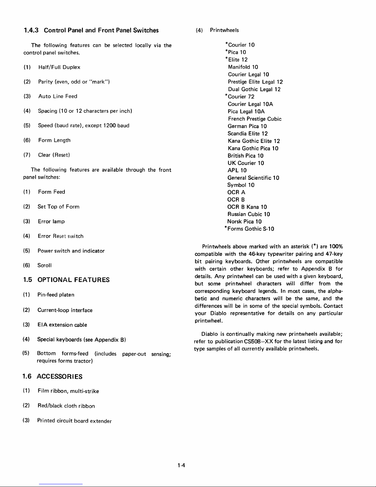
1.4.3 Control
Panel
and
Front
Panel
Switches
(4) Printwheels
The
following features can be selected locally via
control
(1) Half/Full Duplex
(2) Parity (even,
(3)
(4) Spacing (10 or 12 characters per inch)
(5) Speed (baud rate),
(6)
(7)
panel switches:
(1) Form Feed
(2)
(3) Error lamp
(4) Error Reset switch
(5) Power switch and indicator
(6) Scroll
1.5
(1) Pin-feed platen
(2) Current-loop interface
(3) EIA
(4) Special keyboards (see Appendix
(5)
panel switches.
odd
or
"mark")
Auto
Line Feed
except
Form
Length
Clear (Reset)
following features are available
The
Set
Top
of
Form
OPTIONAL
extension
Bottom
requires forms
FEATURES
cable
forms-feed (includes
tractor)
1200
baud
through
B)
paper-out
the
front
sensing;
the
*Courier
*Pica
*Elite 12
Manifold 10
Courier Legal 10
Prestige Elite Legal
Dual Gothic
*Courier
Courier Legal
Pica Legal
French Prestige Cubic
German Pica
Scandia Elite
Kana
Kana
British Pica
UK Courier
APL10
General Scientific
Symbol
OCR A
OCR B
OCR B Kana
Russian Cubic
Norsk Pica
*Forms
Printwheels above marked
compatible
bit
pairing keyboards.
with certain
details.
but
corresponding
betic
differences will be
yqur
printwheel.
Diablo
refer
type
with
Any
printwheel can be used
some printwheel characters will differ from
and numeric characters will be
Diablo representative
is
continually
to
publication
samples
of
10
10
72
Gothic
Gothic
10
Gothic
the
46-key
other
keyboards; refer
keyboard
in
some
essos-XX
all
currently
12
Legal
12
10A
10A
10
12
Elite
12
Pica
10
10
10
10
10
10
10
S-10
with
an asterisk (*) are 100%
typewriter
Other
printwheels are
legends.
of
the
for
making new printwheels available;
for
available printwheels.
pairing
to
with
In
most
the
special symbols.
details
on
the
latest listing
and
47-key
compatible
Appendix B for
a given keyboard,
the
cases,
the
alpha-
same, and
any
the
Contact
particular
and
for
1.6 ACCESSORIES
(1) Film ribbon, multi-strike
(2) Red/black
(3) Printed circuit
cloth
ribbon
board
extender
1-4
Page 15

1.7
RELATED
(1)
HYTERM
MODEL
June, 1976. Diablo Systems, Inc. Publication No.
82333.
(2)
SERIES 1300 HYTYPE
DESCRIPTION,
Publication
(3) SERIES 1300 HYTYPE II PRINTER PARTS
LOG, June, 1976. Diablo Systems, Inc. Publication
No. 82404.
DOCUMENTS
COMMUNICATIONS
1610/1620,
No. 82402.
MAINTENANCE
II
PRINTER PRODUCT
January, 1976. Diablo Systems, Inc.
TERMINAL,
MANUAL,
CATA-
(6)
"C.C.I.T.T.
Transmission, 1973. The
Telephone Consultative Committee, International
Telecommunication Union, Geneva.
(7)
USA
I
NTE
National Standards Institute, 1430 Broadway, New
York,
(8)
DATA
February, 1967. Engineering Director, Data Communications, American Telephone
Publication 41101.
GREEN
STANDARD
RCHANGE,
N.Y. 10018.
SET
103A
BOOK,"
CODE FOR
USAS X3.4-1977. American
INTERFACE
Volume
International Telegraph
INFORMATION
SPECIFICATION,
and
Telegraph
VIII,
Data
and
Co.
(4) SERIES 1600
LOG, November, 1976. Diablo Systems, Inc. Publ
tion
No. 82334.
(5)
INTERFACE
MENT
MENT
INTERCHANGE.
1969. Engineering Dept.,
201
Eye St. N.W., Washington, D.C. 20006.
HYTERM
BETWEEN
AND
DATA
EMPLOYING
EIA
TERMINAL
DATA
TERMINAL
COMMUNICATION
SERIAL
Standard RS-232-C, August,
Electronic Industries Assn.,
BINARY
PARTS
CATA-
ica-
EQUIPEQUIP-
DATA
(9) 113-TYPE
CATION,
Transmission Services, American
graph
DATA
Co_
Publication 41105.
STATION
October, 1971. Engineering Director,
INTERFACE
Telephone
SPECIFI-
and
Tele-
1-5
Page 16

PRINTER
ACCESS
COVER
CONTROL
PANEL
FRONT PANEL
Figure 2-1. Switches, Indicators, and Controls
KEYBOARD
2-0
Page 17

2.1
INTRODUCTION
Only general
section. Specific
HyTerm being used
application being
data
communications
used. However, certain basic
all cases. These
as steps required
Section 3,
tion
and
for
operating
procedures
and
performed
steps
with
Functional
functions
the
network
wi
II
be covered
certain
Description,
not
covered
WARNING
instructions
are
dependent
options
operating
included, as well as
and
the
in which
optional
for
in
this
OPERATING INSTRUCTIONS
are provided in
upon
the
characteristics
the
HyTerm
steps
are
the
same
in
th
is
section,
equipment.
additional informa-
section.
as well
Refer
SECTION 2
this
model
the
of
the
is
in
to
2.2 SWITCHES, INDICATORS,
TROLS
contained
switch panel
side.
inside
2.2.4(6)]
switches are
front
operation.
occurrence
The
more
Others
the
panel,
(Figure 2-1)
frequently
on
the
printer,
which
is
are
contained
printer;
to
expose
adjusted
keyboard,
The
of
an
raise
this panel. Generally,
audible alarm
error.
used
controls
the
keyboard,
just
above
the
on
the
the
printer
before starting
and
printer
is
used mainly
keyboard
control
operation,
controls
AND
and
and
access cover [see
the
are used
to
CON-
indicators are
the
front
on
the
right
panel
located
control
panel
and
during
indicate
the
the
Always
out
carriage. The high-speed
nism
much
and
remotely, a sudden unexpected movement
careful
as
keep hair, fingers,
of
the area
of
faster than an
since
could
when changing ribbons, etc.
around
the
HyType
printing
inflict
injury.
when the access cover is removed,
the
printwheel
printing
/I
printer
ordinary
can be
jewelry,
Be
etc.,
and
mecha-
moves
typewriter,
initiated
especially
2.2.1 Front
Table
2-1
describes
tained
on
the
front
2.2.2 Control
Table 2-2 descri bes
printer
access cover.
Panel
panel.
Panel
(Figure 2-2)
the
switches
(Figure 2-3)
the
switches located
and
indicators
under
con-
the
Figure
2-2. Front
2-1
Panel
Page 18

Table 2-1.
Front
Panel Switches and Indicators
ER
ROR
RESET
FORM
SET
TOF
SCROLL
Name
(indicator)
FEED
(Top
of
Form)
Lights
for
any
of
printer
only
Turns
cleared. Resets
operation;
Moves
Operate
the
HyTerm
setting
memory.
With
character
character
on
remains
switch
paper
Print
tractor
not
exhibit
backed
the
(reversible) pin-feed
cover
if
printing
off
error
see
paper
this
first
line. (Make sure
electronics
of
the
this
switch
is
is
printed,
the
same
down
off
defeats
and
when
quality
or
single-cam
designed
some
up
over page
forms
may
open,
is
lamp
errors
Table
up
to
switch
FORM
printed
line. When several
until
setting
may
to
move
waviness
occur.
the
following
check,
attempted.
after
(see
2-2.)
the
top
after
to
the
LENGTH
on,
the
so
that
the
paper
one
second
the
scroll
the
be
affected
(undirectional)
paper
when
boundaries
For
platen
Function
error
out-of-paper.
the
condition
audible
line
of
the
installing
the
SCROLL
form
position.
paper
moves
the
printing
automatically
characters
after
feature.
top
of
form.
if
the
in
the
the
scroll
(perforations),
best
should
be
conditions:
The
that
alarm).
forms
switch
results, a
(A
next
form.
and
switch
Operating
(Table 2-2)
up
approximately
can be easily seen.
moves
are
printed
the
last
character
The
switch
scroll
feature
pin-feed
reverse
used.
direction,
feature
parity,
last
three
caused
printer
manually
is
off.)
this
down
in
should
is
used
platen.
is
used. Also, if
some
bunching
friction
overrun,
errors
the
check
positioning
This
synchronizes
switch
into
one
to
align
succession,
is
printed.
be
off
along
Since
these
the
printed
platen
framing,
are
indicated
error
has
been
requires
the
second
Before
when
or
or a dual-cam
a clear
them
the
also
loads
the
HyTerm's
after
another
the
printing
the
paper
Turning
with a forms
the
jamming
this
inserting
devices are
line
may
form
to
a
is
of
Audible
POWER (indicator)
POWER (switch)
Alarm
Sounds
same
error
Also
margin. (This
position
Lights
Controls
takes
for
type
do
of a different
sounds
short
whenever
ac
place.
NOTE
When
the SCROLL switch
moves up immediately.
paper does
printed
Therefore, when inserting paper and setting top
form,
and then operate the
or
some
paper to the top line.
1/4
not
when
can
of
power
not
move down
or
the
next
if
the SCROLL switch is on,
space,
other
key, before attempting to align the
second
power
for
sound
the
type
will.
BEL
only
occur
the
"maximum.")
is
to
HyTerm.
each
alarm
character
when
present
When
new
in
is
When
until
printer
~arriage
type
(unless
is received
the
right
the
HyTerm.
power
turned on, the paper
it
is turned
the
next
function
first
return, line feed,
of
error.
errors
have been
or
when
margin has been
is
first
off,
character
is
performed.
turn
it
Additional
reset),
printing
applied, a clear
the
of
off,
set
is
errors
but
the
exceeds
at
some
operation
of
right
print
the
first
2-2
Page 19

Figure 2-3. Control
Panel
Switch
FORM
SPEED
SPACING
AUTO
PARITY
DUPLEX
LENGTH
LF
Table 2-2. Control
This
is a 12-position
the
front
panel.
the
SET
TOF
sure
the
SCRO
5.5,
6, 7,
8,
8.5,
size
of
form
operate
at
This
receive
communications
switch
This
per
non-functional
When
line).
but
move
This
used
on
This
half-duplex,
printer.
"echoed"
received over
properly.
power
on.
is a
three-position
speed
is
non-functional.
two-position
inch.
If
optional
this
switch
When
off,
the
print
the
paper.
is a three-position
on
each
transmitted
two-position
keyboard
In
full-duplex,
back
the
rotary
This
switch
switch
is
depressed
LL
switch
11,
12,
being
used
The
setting
toggle
of
10,
15,
network
toggle
horizontal
until
after
is
on,
each
the
carriage
head
stays
toggle
incoming
characters.
by
character,
switch
data
keyboard
the
host
communications
Panel
Function
switch
is
set
to
is
off.)
Form
or
14
inches.
in
order
of
this
switch
or
30
characters
requirements.
switch
selects
spacing (see
a Clear
at
operation
carriage
return
the
same
switch
Parity
is
selects half-
is
both
data
computer.
link.
used
to
indicate
load
length
This
to
allow
switch
that
horizontal
return
merely
line: a
that
and
the
not
checked
transmitted
is
in
conjunction
the
this
value
can
switch
form
is
also
selects
per
If
the
HyTerm
3.5.3)
is
performed.
also
causes
moves
separate
selects
method
in
or
full-duplex
transmitted
In
full-duplex,
NOTE
size
of
into
be
one
must
feeds
loaded
the
data
second.
spacing
has
a line
the
carriage
Line
the
method
of
parity-bit
MAR K
and
with
the
the
form
the
HyTerm's
line,
(1/6
be
set
to
and
absolute
into
memory
communications
It
must
is
wired
for
of
either
been
employed,
feed
back
Feed
operation
of
parity
generation
position.
data
communications.
automatically
only:
it
will
the
only
SET
TOF
being used
memory.
inch)
or
correspond
vertical
automatically
be
set
according
120
cps
10
or
12
this
(paper
moves
to
the
is
checking
printed
be
printed
data
printed
switch
and
(Make
3,
3.5,
with
tabs
transmit/
speed,
characters
switch
up
left
margin,
required
to
to
be
on
only
is
on
then
4,
the
to
to
this
is
one
to
be
used
In
the
if
that
CLEAR
This
also
pushbutton
accompl
When the optional current-loop interface
must
always be in the FULL position,
of
the
mode
of
operation.
a general reset
of
the
ished
switch
regardless
provides
at
power-on.
2-3
HyTerm
is
used, this
electronics.
This
function
is
Page 20

2-4
Page 21

2.2.3 Keyboard
Several
meet
explains a typical
tion
with
different
many
different
contained
little
difficulty.
here
types
customer
keyboard
can
be
of
keyboards
requirements.
(Figure 2-4),
transferred
are available
This
and
the
to
other
to
section
informa-
keyboards
2.2.3.1.2
are
repeat
function
(about
includes
return,
Repeat
keys:
and
20
times
the
period,
code
per
minus
and
Keys.
when
associated
second)
(hyphen),
space.
Certain
depressed
with
until
backspace,
keys
the
and
that
key
on
each
held
key will
is
released.
line
down,
feed,
keyboard
the
repeat
This
carriage
The
keyboard
portion
ordinary
section,
control
additional
2.2.3.1
regular
character
function
performed.
representing
cations
depressed,
key
2.2.3.1.1
and
called
generate
These
functions
Control
down:
down
key
Vertical
2-4,
Should
depressed
and
them
function
that
ways, e.g.,
code.
three
appropriate
is
typewriter
which
section
ALPHAMERIC
Most
keys
typewriter
(space, tab,
network.
is
printed
"shifted"
"control"
special
control
mode
to
generate a code
the
in
the
Tab
hold
both
the
control
Non-alphabetic
(TAB, LINE
it
is
For a complete
modes
contains
the
alphameric
keyboard.
provides an
is
located on
control
corresponding
such as vertical
CTR L key
at
and
possible
switches.
in
the
At
the
same
that
character
If
the
the
upper
and
the
Control
modes
mode,
control
characters
is
in
alphameric
(VT) code
CTR L
down
the
SHIFT
the
same
mode
keys having
the
same
to
RETURN
for a
code
chart
alphameric
keys:
etc.)
SH I
case
corresponding
Mode. I n
of
effect
and
will prevail.
FEED,
generate
and CTRL-M
three
sections.
section,
alternate
SECTION
when
to
time,
is
FT
character
operation, a third
is
available. This
characters,
tab,
whenever
in
then
section.
on
and
(or LOCK) and
time,
code
listing
particular
in
the
generally resembl ing
To
the
means
the
left,
section
a key
that
key
corresponding
if in
Remote
transmitted
key
or
the
associated
code
addition
such as RS, US, VT,
are used
absolute
the
control
mode,
depress
For
example,
the
keyboard
operate
the
CTR L key will override,
only
one
DEL,
etc.)
in all
three
some
codes
both
of
all
codes
keyboard,
appendix.
The
right
is
the
numeric
of
digit
entry.
which
contains
perform
is
to
horizontal
and
the
the
is
depressed,
printed,
to
the
mode,
the
to
the
communi-
shift
LOCK key
with
is
transmitted.
to
the
"unshifted"
keyboard
mode
is
perform
tab,
CTR L key
depress
shown
legend engraved
generate
modes. Note also
generate
and
release
to
generate
in Figure
"K"
key
CTRL
the
in
two
different
generated
refer
largest
an
A
same as
the
or
the
key
is
code
is
each
mode,
used
to
etc.
special
etc.
is
held
hold
another
once.
keys be
on
same
the
CR
in
the
to
the
2.2.3.1.3
keys provide special
covered
keyboard
are
the
the
right,
The
transmitted
HyTerm
characters
preted.
which
Graphics, red
special
them
The
found
moves
carriage
The
Remote
mode,
a
22.3.2
This
digital
the
may be used
dimple,
Operation
affect
Special Keys.
is
the
CTR L key.
in
Figure 2-4
ESC key
and
ESC
electronics
It
are used
functions
will be covered later
LINE
on
many
the
to
DEL
mode
it
prints
NUMERIC
section
data.
numbered
to
this
section.
in
the
DEL
key
generates
but
does
differently
is
used
to
to
ribbon,
may
FEED
typewriters.
paper
the
left
margin.
key
(see
the
logical NOT
provides a
These
keys
keys
for
entry
provide
of
the
SH I
the
to
up
transmits
SECTION
in
"home"
On
some
functions.
There
worthy
upper
key,
not
interpret
than
initiate 2- and
control
etc. A complete
be
found
key
one
2.2.3.3),
may
the
of
FT
or
of
left,
in
the
the
"escape"
priflt.
This
the following
they
would
special
in
in
this
section
is
similar
It
transmits
line while
the
with
symbol
"10-key
be used
alphameric
numeric
key
CTR
L keys generally
keyboards,
One
of
are
three
special
the
lower
Section
"delete"
pad"
data.
"feel"
mention.
LINE
right.
character,
character
normally
3-character
functions,
listing
1.4.2, and
or
in
to
the
the
not
no
printing.
(-,).
for
interchangeably
section:
Key
for
these
others
FEED
key,
which
causes
one
be inter-
sequences,
such as
of
Section
"Index"
LF
code,
returning
character
In Local
rapid
entry
either
No.5
the
operator.
does
certain
already
on
the
These
on
is
the
or
two
these
all
of
3.
key
and
the
in
of
with
keys
has a
not
2-5
Page 22

Figure 2-5. Printer Controls
2-6
Page 23

2.2.3.3
following
(1) LOCAL. A push-to-Iatch/push-to-release
(2)
(3)
CONTROL
The
control
functions:
selects Local
operates
writer.
functions,
communications
essentially
additional
Remote
ence
the
mode is in
UC
to-release
keyboard
case
alphabetic
acters are
feature.
BREAK. A momentary
Break
normally
computer
this
the
matically,
Paper
occurs.)
substantially
In
mode.
is
made
communications
ONLY
letters
signal
key also clears
print
Out,
SECTION
section
or
Remote
Remote,
it
also
link. Basic
the
same
items
Throughout
to
data
effect.
(Upper
switch.
lower
case
for
printing
characters
unchanged.
to
used
to
for
various
buffer.
and
the
Printer
contains
mode.
the
in
addition
transmits
in
either
requiring
transmission
link, it
Case
Only). A push-to-Iatch/push-
When
latched
alphabetic
are
The
action
the
communications
"get
network
out
any
(A Break
print
Check,
keys
In Local,
same as an
and
receives
operating
case,
consideration
this
is
assumed
down,
and
transmission;
unaffected.
OFF
position
switch
the
attention"
functions.
data
is
also
buffer
is
or
to
with
section,
and
characters
that
transmitted
cleared,
Overrun
to
the
techniques
reception
I ncoming char-
that
may be
2.2.4 Printer Controls
Figure 2-5 illustrates
used by
correspond
(1) Platen knobs. These
the
to
manually
properly.
platen
action -when
the
platen
position
this
platen
Note
that
form
is
HyTerm
form
must
(with
the
switch
must
operator.
the
keyed
in
The
to
of
the
variable
whenever
moved
electronics.
be
SCROLL
be
the
The
items
allow
order
to
right-hand
roll freely
writing line
function.
the
out
To
positioned
switch
operated.
printer
numbers
in
the
illustration.
the
platen
insert
paper
knob
the
knob
is
in
either
can
platen
is
of
synchronization
re-synchronize
for
printing
off)
controls
in
the
and
provides variable
pushed
direction.
be
changed
turned
on
and
control
switch
the
electric
data
that
it
link.
of
following list
to
by
the
the
that
HyTerm
type-
typewriter
over
the
are
only a few
in
the
when
refer-
or
Remote
converts
to
upper
all non-
inhibits this
transmits
This
the
host
Depressing
left
auto-
whenever
condition
commonly
be
rotated
position
in,
it
allows
The
by using
hand,
with
two,
the
first line
SET
TOF
the
to
all
is
in
the
the
the
(2) Platen
forward
form
all
rearward
Intermediate
between
form
the
hammer
done
2.2.5).
(3) Paper bail levers
&
the
(4)
optimum
be
one
using a pin-feed
the
paper,
proper
tractor-feed
(5)
Combination
tion
It
a
a
it
characters
(6) Access cover.
provide
becomes
change
covers
access cover,
rear
called
forms
tion
"skirts"
platen.
position
carriage
the
corner
raise
"short"
position
(7) Paper release lever. I n
releases
repositioned
when
proper
when
tractor-feed
adjust
thicknesses
the
way
of
rear,
by
paper
pulled
of
the
bail rollers
but
operation
of
the
is
marked
the
may
and
the
tractor
terminals.
left
when
of
or
printing
feeding
printing
lever.
or
backward
forward
for
an original
positions
these
several
To
return
first,
copies
it
may
intensity
changing
against
print
forward,
levers)
are held
mechanism.
scale. This scale provides a visual indica-
print
for
per inch.
This
access
necessary
printwheel.
be
is a one-piece
swings
"short"
and
This
that
snap into place
raise
the
carriage
or
power
the
access cover until it snaps free,
remove
access cover, insert
then
tension
or
on
mechanism
This
to
(number
for
single copies,
provide
two
extremes.
and
be necessary
for
optimum
the
impression
and
paper
the
platen.
quality
to
found.
of
and
away
from
when
paper
platen
or a tractor-feed
do
not
in
by
the
pin-feed
head
position
both
10
cover snaps
the
printer
to
replace a
One
The
up
when
access cover,
is
provided
cover
or
remove
to
by
manually
is
OF F). Lift
the
entire
snap
the
the
on
the
removed.
a friction-feed
the
paper.
on
a pin-feed
is
lever moves
compensate
of
carbons).
and
five
for
When
th
is
lever
to
print
bail.
The
This
quietness.
the
is
being
apply
full pressure
the
optimum
paper
along
characters
off
mechanism
ribbon
of
two
first, called
cover
that
raised.
must
on
is
augmented
over
the
the
far
sliding
up
cover.
the
left side
forward
paper,
The
lever
It
platen
used.
the
for
different
It
should
and
all
carbon
form
thicknesses
printing
is
moved
increase
control
platen,
or
different
The
all
access cover,
left
into
position,
allowing it
platen
should
the
quality.
switch
paper
bail
is
necessary
The
bail
(by moving
inserted.
mechanism,
position
clamps
the
typing
per inch
raises easily
when
cartridge
types
the
is
hinged
second
be
used
with
current
by
two
the
ends
(either
the
carriage
on
the
left
To
replace
right side
place.
this lever
should
to
be
or
platen
be
the
way
copies.
on
toward
print
This
(see
holds
for
must
When
on
the
for
or
the
line.
and
12
to
or
of
"long"
at
the
type,
the
produc-
plastic
of
the
first
with
to
front
then
the
into
to
be
back
provide
forward
when
a
is
it
a
be
a
2·7
Page 24

2.2.5 I mpression
The
impression
under
the
access cover,
different
different
ness.
levels
printwhee-\
Set
the
switch as follows:
H High
M = Medium
=
L
intensity;
Low
intensity;
life
of
"Medium"
of
print
intensity;
the
Control
control
toward
fonts
for
for
more
or
"Bold"
Switch
switch
hammer
and
multiple
for
most
I ighter
delicate
types).
(Figure 2-6)
the
right. I t provides
energy
variations
type
to
part
forms
normal
printing,
fonts
is
located
accommodate
in
forms
thick-
only.
printing.
to
extend
(as
opposed
three
the
to
on
the
control
and
no
the
cover
overrun
Occasionally
printer
replacing
with
care.
out
to
override
or
by
replacing
panel lights
printing
(see Table 2-3).
with
its
occurs.
is
closed again, providing
it
may
the
access
platens
position until
or
This
can
"override"
the
cover.
ribbons.
be
position.
it
up
and
the
The
printing
become
cover
accomplished
is
WARNING
open
This
The
pushed
necessary
is
audible alarm
will
then
the
buffer
to
or
removed,
permissible
by
pulling
switch
will
back
in,
either
sounds,
occur
did
operate
e.g.,
when
the
stay
by
when
not
the
when
done
switch
in
the
hand
2.2.6 Cover-Open Switch
The
cover-open
cover. (See Figure 2-6:
differently
operation
each
attempted
time
is
the
while
than
the
access
switch
the
same.)
cover
the
one
The
cover
is
located
the
shown
switch
is
opened
is
under
switch
in
is
open,
the
printer
may
be
the
photograph,
automatically
or
closed. If
the
ERROR
COVER-OPEN
SWITCH
access
mounted
actuated
printing
indicator
but
Whenever the access cover is removed
(e.g.,
when changing ribbons or print-
wheels),
use
care
to
not
accidentally
touch the cover-open switch - this could
allow a sudden
carriage
movement which
might cause injury. Always keep hair,
is
jewelry, etc.,
carriage
IMPRESSION
CONTROL
out
of
and printwheel.
SWITCH
the
area
of
the
Figure 2-6. Cover-Open and Impression Control Switches
2-8
Page 25

2.2.7 Paper-Out-Switch
The
HyTerm
the
last
of
printer.
When
attempted,
the
audible
lost), and a
ERROR
and
the
lamp
RESET
Many
this
feature.
when
the
Because
has
provide
of
been
an
carriage rail,
allow
for
paper-out
Most users will
is,
with
the
ever,
require
the
HyTerm
normal
operation
following
(PIN 23936)
is
the
continuous
this
the
ER RO R
alarm
"Break"
stays
switch
users
prefer
Also, false
proper
this,
the
disabled
override
opposite
occasional
switch
is
paper-out
this
operates
operations.
equipped
switch
indicator
sounds,
the
is
transmitted
on
until
is
operated.
to
operate
paper-out
operating
paper-out
at
the
switch
the I mpression
insertion
not
disabled
prefer
to
feature
feature -it
unattended.
of
the
(Refer
DEFEAT
CL
(PIN
Figure 2-6a. Paper-Out Switch Clip
(1) Raise
(2)
(3)
the
the
top
cover. If
platen
outlined
Locate
near
removal
in
the
the
mounting
the
screw.
switch
desired,
the
switch
or
the
screw, and
to
is a chance
later
date.)
Replace
cover.
ing
(a)
to
the
Check
the
The
a pin-feed
when
position.
access cover.
needed,
instructions.
Section
5.5.2.
paper-out
left
end. Loosen
screw and remove
Be
careful
to
bend
lock ing
cI
simply
operate
following
paper-out
you
top
the
normally.
may
cover,
switch
operating
feature
platen
the
paper
When
with a switch
forms
has passed
is
activated
on
the
print
buffer
over
the
paper
the
HyTerm
indications
constraints
switch
factory.
(on
operate
the
of
paper
on
bottom-feed
Bottom-feed
the
disabled.
is
essential
If
paper-out
to
Figure
IP
400431-01)
Remove
refer
to
Top
switch
just
the
the
not
to
alter
the
switch
ip can
be
rotated
to
This
want
to
reinstall
the
platen,
for
proper
constraints:
is
operational
or a forms
release lever
the
paper
that
senses
through
and
control
is
cleared
the
data
supply
is
without
are
not
on
top-feed
left
end
of
Control
from
the
top-feed
Some
for
example,
you
wish
switch,
2-6a.)
the
perform
platen.
Section
cover removal
behind
left-hand
locking clip.
the
position
operating
left
mounted
the
side
to
is
advisable
the
and
operation
tractor
is
in
release lever
when
the
printing
panel
is
lit,
(data
link.
The
replenished
using
can
appear
followed.
printers
printers
the
front
switch)
top,
so
the
printers.
HyTerm
users, how-
when
to
restore
the
Remove
2.4.3.1
the
for
platen
switch
Tighten
of
the
arm.
(If
under
allow
the
if
there
clip
at
the
access
accord-
on
Iy
when
is
used,
its
forward
is
in
its
is
to
as
rearward
no
The
(b)
the
should
is
are
maintain
prevent
maintain
surface
forms
fastened
(4) If
switch -that
sensing
2.3 BASIC
ular
however,
applications.
establishing
paper-out
items
switch
manual
Note
that
capability
Specific
application
some
are
as
(#82333).
bottom-feed
for
OPERATING
operating
These
the
position
paper-out
supply
floor
be
drawn
sufficient
a false
the
on
must
to
problems
observed,
outlined
bottom-fed
for
paper
procedures
in
which
basic
procedures
include
data
link,
condition
of
continuous
behind
pulled
into
the
forms
which
have full
the
top
check
in
Section 3 of
printers
fed
the
and
(pressure
will
applied
be
sensed.
forms
the
HyTerm,
up
at
least
three
pri
nter.
Th
is
pressure
paper-out
supply
the
contact
cover
exist
situation.
on
HyTerm
of
the
even
the
adjustment
on
the
on
though
the
have
only
paper.
There
from
the
top.
PROCEDURES
are
dictated
terminal
that
paper
error
is
used.
are
common
handling
recovery.
to
must
and
the
feet
is
necessary
the
forms
Do
desk
or
is
placed.
the
paper
HyTerm.
the
maintenance
one
paper-out
is
no
paper-out
by
the
There
to
techniques,
paper),
rest
forms
as
they
NOT
other
The
rack
above
of
the
partic-
are,
most
on
to
to
CAUTION
Keep papers,
items
that
six
inches
on
all
inches clearance between the
adjacent
might
(15cm)
sides.
walls.
books,
impede
away
Also,
and 0 ther
airflow
from
provide
desk
at
the
HyTerm
at
least
HyTerm
top
least
six
and
2.3.1 Turn-On
When
the
POWER
automatically
operation.
is
municate
the
proper
switch
applied
the
terminal
are
set
the
modem
performs
However, unless
over
the
position,
be
latched
without
in Local
properly,
and
the
2.3.2 Loading
The
procedure
or
bottom-feed
a
shorter
FORM
procedures
certain
paper,
2.3.2.1
although
tractor
This
or
longer
LENGTH
that
the
SCROLL
depress
TOP-FEED
procedure
it varies
is
used.
the
switch
a Clear
the
data
link
etc.)
it
down
first.
inserting
and
until
the
host
an
error
the
data
computer.
Paper
for
loading
printers.
than
switch.
applies. Before
SET
is
slightly
If
the
previous
Use
switch
TOF
switch.
PRINTER
the
same
when
is
turned
operation
terminal
(paper
loaded,
is
recommended
Then
power
into
paper
is
link
is
paper
is
different
the
form
form
the
one
of
positioning
is
off.
After
as
for a regular
a pin-feed
on,
the
HyTerm
and
is
ready
is
ready
to
all
switches
the
LOCA L
can
be
the
network.
loaded,
established
all
switches
for
between
top-feed
being installed is
used,
adjust
the
two
following
the
paper
positioning
typewriter,
platen
or a forms
for
com-
in
safely
Leave
the
be
the
2-9
Page 26

2.3.2.1.1
in a printer
Standard
having a
(1) Make sure
pressure
(2) Pull
the
(3) Holding
desired margins,
platen.
(4) Roll
the
mately
between
(5) Push
(6)
the
the
paper.
Position
the
right-hand
positioning
2.3.2.1.2
for
both
(1) Pull
Pin-Feed Platen. Use
inserting
sides
on
the
normal
used.
Pull
(2)
the
(3) Release
(4)
I nsert
Push
the
grasped
paper
above
(5) Align
the
one
pins
clamp.
(6)
Straighten
portion
portion
(7)
Snap
down
(8) Position
Position
(9)
the
right-hand
positioning
(10) Depress
When using a
release lever
position,
paper.
proper
paper
Occasional
the
two
sets
a:-e I if
ted
up
put
pressure
inserted
and
paper
on
2.3.2.1.3
lifting
the
the
bail
paper.
to
Tractor
(Friction-Feed)
friction-feed
the
paper
on
paper).
paper
bail
away
the
paper
aligned
insert
paper
into
1/2
inch above
the
ribbon
and
paper
bail
back -the
the
paper
for
platen
is
necessary.
continuous
1/2
inch
paper
operating
paper
both
the
paper
paper
coming
through
the
typing
set
in
the
in
front
behind
the
the
paper
the
paper
centers:
release lever
position
bail
forward,
pin-feed
into
through
up
until it
line.
of
holes
the
platen,
paper
of
the
platen.
second
bail
for
forms,
platen
is
necessary.
the
SET
TOF
NOTE
pin-feed
must
removing
If
the lever
paper
feeding
will
result.
sheets
of
paper
of
pins can be inserted
and
the
paper
on
the
paper).
same as
the
swing all
paper
for
clamps
the
the
Feed
platen
release lever
from
the
horizontally
it
into
the
the
printer
the
card
the
paper).
the
first line
knob
in
the
having holes
forward.
when
away
paper
clamps.
the
printer
until
the
in fro'1t
of
is
approximately
in
the
form
and
snap
by aligning
the
platen
paper
clamp.
back
against
the
first line
knob
in
switch.
platen,
be in
pressure
is
pushed
and
tearing
narrow
if
release lever
In
this
standard
out
of
way back, so
Assembly.
Platen.
Load
as follows:
is
back
platen.
to
provide
printer
until
behind
it
is
guide (the shield
rollers
should
of
printing.
and
rotate
following
procedure
punched
This
a pin-feed
from
the
platen.
behind
the
leading edge
the
platen.
4-6 inches
(either
side)
down
the
the
edges
with
the
edges
the
paper
of
printing.
and
rotate
the
paper
its
forward
from
the
back, im-
of
the
enough
the
is
case,
to
fit
pin-feed
pushed
the
friction-feed
the
way
allows
that
the
rollers
The
tractor-feed
paper
(to
put
the
the
approxi-
ride
Push
it
if fine
is
platen
platen.
can
Pull
the
with
paper
of
the
of
the
clamps.
Push
it
if fine
between
clamps
back
paper
platen,
the
rest
on
on
the
be
(to
assembly requires
holes (on
form.
used,
(1) Pull
1/2
If
non-standard
the
tractor-feed
the
(2) Release
(3)
Tip
the
until it rests in
tension
platen
(4)
Insert
printer,
down
behind
the
leading edge
inch
paper
both
tractor
outfeed
on
the
will pull
the
first
over
the
use
centers)
forms
mechanism
bail
forward,
feed
(top)
the
paper
the
paper
of
the
the
infeed (lower)
the
platen.
is
of
continuous
punched
or
individual
should
away
paper
paper
support
forward
feed rollers so
through
continuous
Turn
on
be
from
clamps.
position.
the
paper
the
paper
forms
both
sheets
removed.
the
up
and
This
that
printer.
forms
support,
through
several inches above
with
sides
are
platen.
forward
restores
turning
into
the
feed
of
to
and
until
card
the
be
the
the
guide.
Tip
the
(5)
at-rest
outfeed
position.
feed rollers
the
printer.
(6) Pull
is
(7)
(8) Align
the
paper
inches above
Place
the
form
assembly
and
the
right-hand
necessary,
the
right-hand
tractor
adjust
right-hand
clamp
screw.
(9)
Push
the
paper
(10) Position
paper
only
and
hand
the
up -the
to
get
it
cannot
platen
so
the
through
the
over
close
form,
tractor
tractor
bail
form
first
the
forms
be used
knob
paper
This
paper
typing
the
the
place
assembly,
for
proper
to
either
back
for
the
of
started
in
and
support
releases
back
tension
can be pulled freely
until
it
is
approximately
line.
teeth
on
the
left-hand
clamp.
it
over
the
and
close
form
width
clamp
screw
and
side.
Then
against
the
tractor
first line
the
for
rotate
of
typing:
continuous
through
the
printing. Push
it
if fine
down
to
on
the
paper
through
tractor
teeth
on
the
clamp.
by loosening
sliding
retighten
feed.
turn
forms
is
used
tractor-feed
the
right-
positioning
its
6-8
the
If
the
the
the
is
necessary.
the
SET
TOF
with
switch.
of
the
and
the
forms
the
form
tractor
tightening
already
can be
clamp
the
accom-
screws, reposi-
screws.
installed
in
This
the
(11) Depress
Horizontal
(12)
plished by loosening
tioning
should
positioning
the
be
done
tractors,
tractors.
The
tractor-feed
mechanism,
other
backward
the
printer
the
platen.
jamming in
2.3.2.2
The
and
requires a
is
certain
has
been
the
bottom
reinstalled
(1)
(2) Release
but
direction.
(down)
and
This will keep
the
BOTTOM-FEED
bottom-feed
the
curved
removed;
if
at
any
Pull
the
paper
both
it
cannot
If
more
pull
printer.
forms
paper
this
cradle
time
tractor-feed
pulls
the
forms
it
becomes
the
"push"
than
forms
necessary
just a few
back
the
forms
them
PRINTER
printer
tractor
uses
to
only
pull
cradle (deflector)
the
paper
will
is
left installed. This cradle
to
allow normal
bail
forward,
away
paper
through
through
from
the
not
from
clamps.
the
back
through
to
roll
lines, reach
while
bunching
continuous
forms
through.
under
feed
properly
top-feed
the
platen.
printer
the
behind
turning
up
the
may
paper
in
the
forms
and
forms,
Be
platen
from
be
use.
2-10
Page 27

(3)
Insert
the
through
forms
chuten Push
protrudes
leading edge
the
slot
far
enough
in
the
the
bottom
forms
to
be
of
the
up
pulled
continuous
of
the
until
the
from
printer
leading edge
the
top.
forms
into
the
NOTE
To
provide
leading edge
diagonally, insert the
forms
(4) Pull
the
tractor
the
form,
(5) Push
the
(6) Position
(7) Depress
easier paper insertion,
of
chute,
and
push
form
up
and
feed. Snap
and
paper
the
the
down
snap
down
bail back against
paper
for
SET
TOF
the
continuous
"point"
it
up.
position
the
the
the
first I ine
switch.
it
over
clamps
other
the
fold
forms
into
the
on
one
clamp.
forms
of
printing.
the
the
pins
on
side, align
tractor.
the
NOTE
Nega
tive
paper
recommended when the
mechanism
is
used.
movement
bottom-feed
is
not
2.3.3 Establishing the Data Communications Link
The
data
communications
two
"modems"
puter
or
remote
the
modems.
ing
the
digital signals used
computer
and
received over
The
specific
communications
computer
and
upon
necessary
host
to
computer
transmission
(modulator/demodulators),
terminal,
The
into
audio
the
procedure
link
is
dependent
network
know
or
speed
sion being used (halfuse,
whether
computer
return.
can be
completed.
switch
tions
link: it
SPACING
If
a leased
established and it
HyTerm
configurations,
the
HyTerm
installed, all
established
key
to
upper
is
set
When
set
accordingly,
All
should
switch,
and release
control
it
enter
Remote
up
these
control
be
mayor
phone
the
is
powered
is
then
to
set
depending
is
modems
signals
telephone
between
upon
characteristics.
the
basic
remote
(baud
or
case
transmit
factors
and
switches
prior
may
necessary
the
data
switches set,
only
mode
link includes
and
the
perform
by
the
capable
lines.
needed
the
the
type
operating
terminal,
rate),
the
full-duplex),
letters
are
a line feed
are
known,
the
communications
other
to
establishing
not
be necessary
upon
line
is
used,
only
LOCAL
link
is
normally
up
and
made
necessary
and
begin
telephone
the
function
HyTerm
of
being
to
establish
HyTerm
of
modem
In
every
characteristics
such
type
of
the
type
required,
with
the
control
than
the
network
to
characteristics.
the
link
apply
switch.
established
fully
etc.).
Once
to
release
data
commun
the
HyTerm,
the
host
lines
between
of
chang-
and
the
transmitted
the
and
the
being used
case, it
of
as its
data
transmis-
of
parity
and
if
the
each carriage
switches
link can be
the
SPACING
communica-
to
set
is
always
power
to
I n dial-up
ready
(forms
the
link
the
LOCAL
ications.
com-
host
data
host
the
data
in
host
the
the
after
The
procedure
upon
which
procedures
some
of
to
the
modem
tions
for
carefully
the
the
observed.
in establishing
end
of
the
are given here
possible
situations,
operating
particular
modem
the
data
link
link originates
to
familiarize
and
steps.
However, specific instruc-
being used
to
the
the
relate
should
is
dependent
call. General
operator
the
with
HyTerm
always
be
NOTE
A
typical
requires
ications
answer
the data
host
the
call
and
be
performed
2.3.3.1
ORIGINATING
ACOUSTIC
Before
actually
following
(1)
preliminary
Determine
receiver in
coupler
identification.
acoustic
(2) Make sure
switches
(3)
Insert
the
(4) Make sure
After
these
establish
is
(1) Pick
the
up
computer
establishment
link
within
tone
from
the
link
is
not
computer
the
connection
again.
COUPLER
establishing
steps:
the
correct
the
acoustic
is
usually
marked
(Do
coupler
are
correct
the
set
the
acoustic
yet
LOCAL key
correctly,
paper
preliminary
link as follows:
the
telephone
network
of
a data
30
seconds
computer
completed
may
disconnect
procedure
usually
commun-
after
the
begins.
in
time,
the
must
If
A DATA LINK WITH AN
the
data
link,
placement
coupler:
"cord",
not
place
- leave
and
or
forms
coupler
steps
receiver
of
one
or
the
it
"on
hook"
is
depressed,
power
into
power
have been
and
the
has
phone
is
on.
the
is
on.
dial
perform
end
some
HyTerm.
completed,
the
telephone
of
the
similar
in
the
for
now.)
all
control
the
host
computer.
(2) When
(3)
acoustic
light,
will
(4) Release
the
indicator
switch
is
exists
tions can
Procedure
the
host
tone,
quickly
the
acoustic
cation
at
the
the
DATA
HyTerm
occurs
other
mode
end
cups
end
After a second
coupler
something
probably
the
LOCAL key on
HyTerm into
is
to
extinguish it.
that
must
take
in
Section
place
prior
is
placed
or
computer
the
on
to
of
the
before
two
should
sends its
telephone
the
coupler.
establishing
link
must
the
telephone
into
the
the
"carrier"
illuminate.
has gone wrong
have
to
be
repeated.
the
Remote
mode.
illuminated, press
If
it
comes
be
corrected
before
place. Refer
2.3.4.
receiver firmly
(If voice
the
place his
acoustic
indicator
and
keyboard.
If
the
back
data
to
the
Error Handling
"answer-back"
into
communi-
link,
the
person
modem
receiver
at
coupler.)
on
If
it
does
not
the
procedure
This
puts
the
ERROR
Error
RESET
on,
an
error
communica-
in
the
the
2-11
Page 28

When
the
data
communication
disconnected
be
acoustic
coupler
by simply removing
and
placing it back
cradle. (The link can also be
computer
2.3.3.2
TYPE
that
most
about
2.3.3.3,
(1) Make sure
(2) I nsert
(3) Pick
at
any
time.)
ORIGINATING
A DATA LINK WITH A BELL-
MODEM
There are several
can be used with
of
them
"originate
different
is
essentially
only"
the
modems
terminal
if applicable.) Proceed as follows:
the
LOCAL key
switches are set
the
up
the
button
(which will light,
correctly,
correct
telephone
paper
receiver and depress
is
complete,
the
disconnected
types
of
but
the
same. (See
in
is
depressed, all
and
power
or
forms
on
most
receiver
on
the
Bell-type
the
operation
the
next
is
on.
into
the
modems).
the
link can
from
the
telephone
by
the
host
modems
information
section,
control
HyTerm.
the
TALK
of
2.3.3.3
be used
ORIGINATE-ONLY
MODEMS
Originate-only modems, such as
to
communicate
with a
the
host
computer
preceding instructions. An originate-only
be used
only
modem.
modem,
must
back"
operator
the
depressed will allow
automatically,
cation
is
end
to
if
the
When one
go
tone.
2.3.3.4
Answering a
receiver
In
many
before
only
necessary
of
the
communicate
remote
it
must
into
the
with
terminal does
of
the
terminals has an originate-only
initiate
data
the
mode
another
call,
first,
remote
not
have an originate-only
and
to
supply
ANSWERING A DATA LINK CALL
call may
intervention. With
"on
and
cases
it
entering
to
link places his
hook"
any
the
data
is
desirable
the
be sure
be
automatic,
many
modems,
and
leaving
incoming calls
link will be established.
to
carryon
data
mode.
that
the
person
modem
in
the
Bell
modem
the
or
the
to
When
DATA
type
113A, can
using
terminal,
other
the
"answer-
it
may require
simply
DATA
be
"answered"
voice
communi-
this
at
the
answering
mode first.
the
can also
but
terminal
leaving
button
occurs,
it
(4) Dial
"answer-back"
the
modem,
cradle. On
and
the
cation
the
attendent
modem
The
before hanging up the
the receiver is placed on the cradle while
the TA L K
will
(5) Release
ERROR
RESET switch
an
error
communications
Handling Procedure
When
disconnected
be
button.
the
host
The
computer.
the
host
computer.
and
most
DATA light will
precedes
at
in
the
DATA
DA
TA
button
be
disconnected.
the
LOCAL key
indicator
exists
the
data
communications
by simply depressing
link can also be
When it responds with its
tone,
depress
then
modems,
the
establishment
the
host
mode
place
the
turn
the
DATA
the
receiver back
TALK
on.
(If voice
computer
first.)
button
light will go
communi-
of
the
data
must
place his
NOTE
button
to
must
be depressed
phone
receiver:
is depressed, the
on
the
is
illuminated, depress the Error
if
link
keyboard.
extinguish it. If it comes back on,
that
must
be
can
take
in
Section 2.3.4.
corrected
place. Refer
are finished,
disconnected
the
before
to
the
the
modem
at
any
on
on
its
out
link,
If
the
data
Error
link can
TALK
time by
Some
modems do
this case
possible,
neither
but
answering
have a separate,
all
cases, follow
modem
being used.
not
voice
communication
complete
the
instructions
2.3.4 Error Recovery
So
me
error-recovery
dependent,
procedures
in
Table 2-3.
Certain general practices
any error-recovery
sive
errors
the
data
switches has been
and
other
several
causes
others
not
rectify
and
try
to
occur
link, it
switches
errors
others
as well.
the
to
begin
and
cannot
be followed if
procedure.
immediately
is
likely
set
wrong. Check
to
make certain
occur
simultaneously,
to
occur,
If
the
remedial actions given in
troubles, depress
operation
have receivers,
nor
is
automatic.
telephone
Other
connected
pertaining
procedures
be covered here.
errors
should
should
that
be considered during
For
example,
after
turn-on
one
or
more
the
they
often
and
rectifying
the
CLEAR
again
from
the
or
"handsets":
call origination
modems
to
the
to
them.
particular
may
are application-
The
general
occur
are
shown
should
or
of
exces-
establishing
the
control
SPEED, PARITY,
are
set
properly.
one
type
of
error
one
will solve
the
table
the
do
pushbutton,
beginning.
in
is
In
If
2-12
Page 29

2.3.5 Keyboard Control
Most
of
the
can
be
computer.
ator,
and
is
items
standard
controlled
Several
so will
contained
by
functions
not
be
in
and
either
covered
Section
of
Features
special
features
the
operator
are rarely used
here:
information
3,
Functional
Those
panel
of
the
terminal
or
the
host
by
the
oper-
on
these
Description.
for
information
operating
going
otherwise by
Table 2-3. Error Recovery
features
switches
parameters
"on
line"
under
have
on
to
network
control
already
these
should
the
characteristics.
of
been
features.
be
host
the
front
explained;
Margins,
set
in
Local
computer,
panel
see
tabs,
unless
and
Section
and
mode,
control
2.2
other
before
dictated
Error
Indication
Audible
Alarm
Sounds,
ERROR
Lamp
Lit
Possible
Causes
1.
Parity
Framing
2. Paper
3.
Printer
Cover
4.
Overrun
5.
"Break"
6.
Received
or
Error
Out
*
Check*
Open
Error
Remedial
Action
Locate
whether
errors
Depress
if necessary.
Revert
once.
to
RESET
Depress
necessary,
then
Close
*
Depress
if necessary.
Perform
erroneous
correct
are excessive,
RESET
to
Local
Insert
Remote
switch
CLEAR
return
printer
RESET
steps
mode.
enter
to
character(s),
character
switch
mode.
and
position
Turn
to
extinguish
to
Local
Remote
access cover. Depress
switch
·predefined by
can
check
settings
to
extinguish
If
SCROLL
new
SCRO
extinguish
mode
mode.
to
extinguish
the
forms,
indicator.
and
Request
represented
be
ascertained
of
indicator.
switch
depress
LL
switch
indicator
set
tab
RESET
indicator.
network
by
'-,'
symbol.
from
surrounding
SPEED and PAR ITY switches.
Request
is
on,
SET
TOF
back
on,
Request
retransmission.
and
stops,
to
for
this
restore
margins,
extinguish
retransmission.
Request
situation.
retransmission
turn
it
once,
if
necessary. Depress
printer
etc.,
indicator.
retransmission
off
and
and
carriage. If
as
needed;
Decide
text.
space
return
If
Audible
Alarm
Sounds,
ERROR
Lamp
Not
Lit
*
NOTES:
Automatically
1. Remedial
dictated
2.
"Requesting
repositioning
dictated
3.
After
depending
Right Margin
1.
Exceeded
2. BEL
depressing
code
Received
actions
by
network
retransmission"
forms
by
network
upon
clears
CLEAR,
network
Check
necessary.
Perform
print
buffer
and sends
listed are general in
requirements.
usually involves depressing
in
the
printer,
requirements.
additional
characteristics.
depressing
setting
nature
steps
steps
"Break"
such as
2-13
of
right
dictated
to
and
may
the
SET
setting
margin,
by
network
host
computer.
be
replaced
the
TOF
margins
readjust
for
BREAK
key,
and/or
and
and/or
this
or
modified
key,
tab
request
situation.
but
additional
other
operations
stops,
retransmission
by specific
steps,
etc.,
may
procedures
such
may
also be
be
required
if
as
Page 30

2.3.5.1 MARGINS (ESC 9, ESC 0)
When power
operation
set
margin, first position
location. Then depress
to
change
right margin.
need
cancels
carriage returns will
Backspacing
never
position 1).
continue
new setting,
disabled. Printing can
way
as right margin
further
previously
2.3.5.2
is
to
their
the
not
be cancelled: setting a
the
Once
the
beyond
Once
the
past
to
the
characters
CARRIAGE MOVEMENT
is
first applied,
performed,
maximum
left
If
a
old one.
left margin has been changed,
is
permitted
the
right
the
the
audible alarm
"extreme"
after
printed
both
the
right
outward
the
the
margin
second
return
"extreme"
margin has been
new margin,
continue
right margin position (same position
CLEAR
will be
there.
positions.
carriage
change
to
ESC key, followed
or
the
0 (zero) key
is
new
the
carriage
past
the
left margin position
but
sounds.
past
operation),
overprinted
or
when a CLEAR
and
left margins are
To
the
desired
desired,
as
the
the
margin
to
the
new
left
changed,
the
carriage passes
The
keyboard
right margin
at
which
on
change
to
automatically
new position.
the
either
new
margin
by
the
9 key
change
first setting
subsequent
margin,
(print
printing
is
all
point
characters
the
but
can
the
not
the
any
2.3.5.3
These include line feed, negative line feed,
vertical
FEED
carriage
down
LINE FEED key.
line), depress
key. This
original line
down
case
exponents
a
respective
characters
PAPER MOVEMENT
There
are several
tab.
Vertical
To
accomplish a normal I ine feed, depress
key. A normal line feed also occurs
return
To
perform
one
line), depress
To
perform
is
To
perform
1/2
line), depress
liD"
key. This
or
half-I ine feed.
For
both
upper
will have no
functions
tab
when
the
a negative line feed
a half-line feed (to move
the
ESC key followed by
used
for
typing subscripts
after
performing a negative half-line feed.
a negative half-line feed (to move
is
to
return
half-line feed
case (capital) letters;
that
affect
is
covered in Section
AUTO
LF
switch
the
ESC key before operating
the
ESC key followed by
used
for
typing
to
the
original line
operations,
effect.
(to
the
or
make sure
paper
movement.
form
feed,
3.
the
as
a result
is
on.
move
the
the
paper
upper
case
to
return
the
the
superscripts
after
performing
to
the
lower case
and
LI
of
paper
up
to
paper
upper
use
NE
a
the
1/2
"u"
the
and
the
Normal carriage
printing each character.
cause
the
same
usually
are
or backspacing
always causes
key
but
it
is
on.
The
the
next
set
to
the
TAB key causes
right
per inch and
To
tab
stop
the
digit 1.
are no restrictions as
distance between stops.
To
cleared, and
8.
To
followed by
See Section 3
repeat
does
not
TAB key causes
previously-set
the
right
print
position
set
tab
position.
clear individual
clear
movement
operation
keys, which will cause repeated spacing
if
they
the
move
of
the
(print
print
position
stops,
Then
For
normal 10-pitch
then
depress
all
tab
stops
the
digit 2.
for
information
is
accomplished as a result
The
SPACE and BACKSPACE keys
as
on
a regular
are held depressed.
carriage
the
the
first
to
tab
to
return
paper
unless the AUTO
the
carriage
tab
stop.
If
present
carriage position,
carriage
space
depress
the
stops, first
the
to
position
158
for
the
the
or
number
ESC key followed by
at
once, depress
on Absolute tabbing.
typewriter.
to
the
to
move
there
are
move
to
132
for
12
characters per inch).
carriage
ESC key followed by
12-pitch spacing,
of
tab
stops
tab
to
The
RETURN
left margin,
LF
to
the
no
tab
operating
the
10
characters
to
the
or
the
stop
the
ESC key
of
They
switch
right
to
stops
extreme
desired
there
to
the
to
be
the
digit
A form feed can be accomplished in
the
As previously explained,
top
line
of
the
next
form
the
front
panel
is
operated.
initiated
This
while
however,
the
If a form
the
2.3.5.4
change
change back
upper
"b"
restore black printing.
remotely
attempt
installed: if red printing
ribbon,
printing,
ink remains
from
most
is
normally
operating
that
FF
code
feed
front
panel FORM FEED switch
RIBBON
The
HyTerm
to
red,
case A and B
will have
The
choice
by
red printing,
the
and
done
another
when this
is
transmitted
is
desired
CONTROL
is
execute
to
black,
no
effect. A CLEAR
of
red or black can also be
the
host
ribbon will
printing will
on
the
printwheel
keyboards
initialized
characters
be
form
when
This same action can also be
by holding
key, usually
method
to
the
without
the
2-character sequence ESC A.
execute
computer.
certain
is
attempted
not
occur
type
either
will be moved
the
FORM FEED switch
by producing
down
is
used in
communications
transmitting
must
for
printing in black.
ESC
B.
- the lower case
If
the
to
have a
be lifted
only
face.
the
the
the
Remote
be
used.
Make sure
operation
host
computer
two-color
on
a single-color
into
as long as
of
two
up
FF
CTRL
"L."
network.
the
F F
to
use
"a"
will also
controlled
ribbon
position
sufficient
ways.
to
the
on
code.
key
Note,
mode,
code,
To
To
the
and
is
to
for
2-14
Page 31

2.4
OPERATOR
There
formed
operators
duties
special
are certain
routinely,
will
perform ~ of
need be
DUTIES
operator
such as replacing ribbons. However,
performed
duties
that
must
the
items covered here. These
only
as
the
need arises.
be per-
few
For
not
be
caught
Heed
area
underneath
the
operator's
worn
by
the
the
warning label
when
printer
the
own
safety,
operating
carriage
on
carriage.
dangling jewelry
the
HyTerm - it
and
the
base
inflict
of
the
could
minor
printer,
should
get
injury.
in
the
CAUTION
Be
extremely careful
beverages
metal objects, such
staples, near the HyTerm.
metal objects be dropped
machine,
not
the electronic circuits
Immediately unplug the
the wall.
metal objects
be
located.
a
liquid
nance personnel clean
interior
use
The
HyTerm printer
few moving parts. Because
ally trouble-free
operator
can help
and
other
or
any
liquids
attempt
it
to
use
After
the
may
be removed
If
they
cannot
has been spilled, have mainte-
of
the
unit
is
electronically
of
operation
to
extend
exercising reasonable care in
and
other
ages,
possibly-contaminating materials
printer.
in
the handling
liquids,
as
it;
cord
before
and
paper clips
Should
into
spilled
on
severe
damage
could
power
cord
is
unplugged,
if
be
found,
and
inspect the
attempting
it,
result.
they can
controlled
this, it will provide
for
long periods
these
trouble-free periods
the
handling
of
small
and
any
the
do
to
from
or
if
to
of
of
food,
and has
exception-
time.
The
bever-
around
the
by
2.4.1 Replacing Ribbon Cartridge
WARNING
Be
careful
cover-open switch.
(1)
Raise
2.2.4(6)]
(2) Depress
old ribbon straight up.
(3)
Remove
the
small ribbon advance
direction indicated by
all
slack
(4) Holding
top,
guide
guides (Figure 2-9) and
and
the
until
the
in
place.
(5)
Replace
not
to
accidentally operate the
or
remove the printer access cover [see
.
both
ribbon clamps (Figure 2-7),
the
new
cartridge
from
knob
the
arrow,
from
the
ribbon.
the
new
cartridge with
the
ribbon
around
down
card guide.
Then
ribbon clamps snap
the
access cover.
the
the
between
push
into
and
its
container.
(Figure 2-8)
enough
to
DIABLO name
two
metal
the
printwheel
the
cartridge
position
to
lift
the
Turn
in
the
remove
on
ribbon
down
hold
it
RIBBON CLAMPS
Figure 2-7. Ribbon Clamps
2-15
Page 32

RIBBON
ADVANCE
KNOB
RIBBON
CLAMPS
~;...---
Figure 2-8. Ribbon Advance
RIBBON GUIDES
Knob
CARD GUIDE
PRINTWHEEL
.
Figure 2-9. Ribbon Cartridge Placement
2·16
Page 33

2.4.2
Changing Printwheels
NOTE
It
is recommended
turned
wheels.
with
brush the cover-open switch
dentally operate
could
which
off
whenever replacing
If
a
printwheel
the
power
allow
a sudden carriage movement
might
inflict
that
on,
it
in
injury.
must
be
any
the
careful
power
be
or
way - this
be
print-
replaced
not
to
to acci-
(4) Remove
knob
at
printwheel
(5) Remove
position
rotating
2-12)
(Figure 2-11).
(6) Press
the
the
printwheel
the
printwheel
in
its
the
it
over
the
wheel until its
is
lined
hub
of
protective
new
printwheel
the
printwheel
up
with
the
wheel firmly
by
pulling
hub
(Figure 2-10). Place
case.
from
shaft
alignment
the
shaft's
to
lock
on
the
rubber
its case
(Figure
hole (Figure
alignment
it
in place.
the
and
2-11),
tab
(1) Raise
or
(2) Remove
(3) Pull
wiil
the
snap
"remove
the
carriage
the
access cover [see
ribbon cartridge (see 2.4.1).
into
toward
the
you,
away
position shown
PRINTWHEEL
KNOB
2.2.4(6)].
from
the
in
Figure 2-10.
platen.
It
(7) Push
will snap
(8) Replace
(9) Repiace
the
carriage back
into
the
the
into
place.
ribbon cartridge.
access cover.
position
for
printing.
It
Figure 2-10. Carriage Tilted
2-17
for
Printwheel Access
Page 34

ALIGNMENT
TAB
PRINTWHEEL
SHAFT
__
_
Figure 2-11. Printwheel Installation
ALIGNMENT
HOLE
Figure 2-12. Printwheel
2-18
Page 35

2.4.3 Changing Platens
Platen removal
switching
removal
vary between
is
from
the
From
Push OUT
the Lower
Portion
Skirt
and
installation
one
type
same for all
platen types.
the
Inside,
Against
Front
of
the
of
platen
types:
is
necessary
to
installation procedures
only
another.
when
Platen
Terminals
ends
of
the
platen can be removed. Refer
removal instructions.
portion
skirt
from wedging against
the
of
equipped
platen
the
skirt
with plastic platen
must
have
Outward
is
necessary
the
top
"skirts"
these
skirts removed before
to
Figure 2-13 for
pressure
on
to
keep
th
covers.
At
the
Same Time,
Push
the
Front
the
Inside
Corner
Skirt Down
and Toward
Center
of
the
the
is
the
Printer
Until
lower
part
of
over
of
the
front
the
PLATEN
LATCH
Figure 2-13. Platen
PRINTER
SIDE FRAME
Skirt
COLLAR
Removal
PLATEN
VARIABLE
Projection
KNOB
Free
of
the
Then Lift
Front
of
Straight
Remove
the
the
UP,
the
A
is
Cover.
Skirt
and
Skirt.
,--------
Figure 2-13a. Platen Removal
2-19
PAPER
BAIL
Page 36
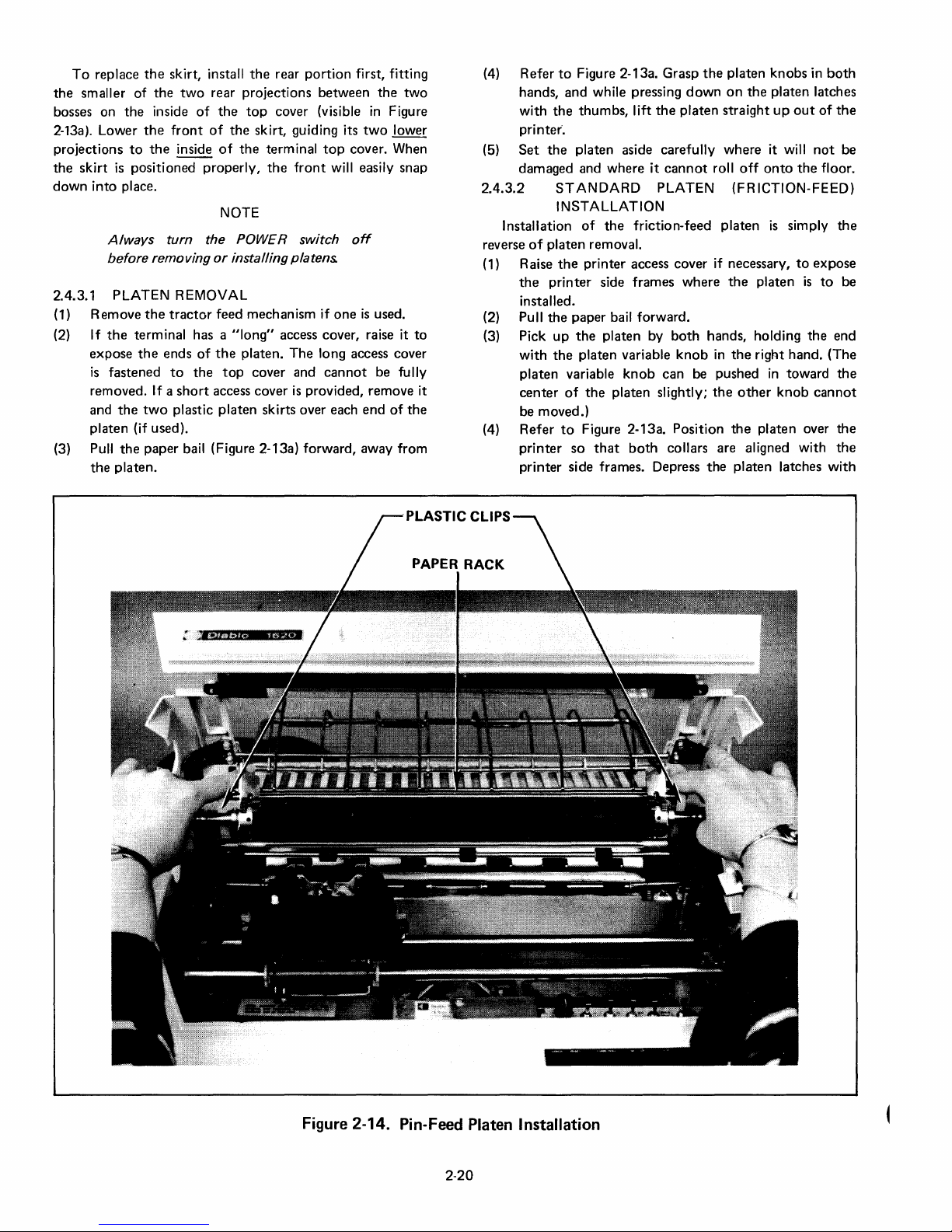
To
replace
the
smaller
bosses on
2-13a). Lower
projections
the
skirt
down
into
the
of
the
the
inside
the
to
the
is
positioned
place.
skirt, install
two
rear projections
of
the
front
of
the
inside
of
properly,
NOTE
Always
before
turn
removing
the POWER switch
or
installing platens.
2.4.3.1 PLATEN REMOVAL
(1) Remove
(2)
If
expose
is
removed.
and
the
the
terminal has a
the
fastened
If a
the
two
tractor
ends
to
short
plastic
feed mech an ism if
"Iong"
of
the
the
top
access cover
platen
platen (if used).
(3) Pull
the
the
paper bail (Figure 2-13a) forward, away from
platen.
the
rear
portion
top
cover (visible
skirt, guiding its
the
terminal
the
front
access cover, raise it
platen.
The
cover and
is
provided, remove it
skirts over each
first, fitting
between
top
the
two
in
Figure
two
lower
cover. When
will easily snap
off
one
is
used.
to
long access cover
cannot
be fully
end
of
the
(4) Refer
hands,
with
printer'.
(5)
Set
damaged and
2.4.3.2
Installation
reverse
of
(1) Raise
the
installed.
(2) Pull
(3) Pick
with
platen
center
be moved.)
(4)
Refer
printer
printer
to
Figure 2-13a. Grasp
and
while pressing
the
thumbs,
the
platen aside carefully
lift
where
it
STANDARD
INSTALLATION
of
the
friction-feed
platen
removal.
the
printer
printer
the
paper
up
the
the
platen variable
variable
of
the
to
Figure 2-13a. Position
so
access cover if necessary,
side frames
bail forward.
platen by
knob
platen slightly;
that
both
side frames. Depress
the
platen
knobs
in
both
down
on
the
platen latches
the
platen
cannot
straight
where
roll
off
up
it will
onto
out
the
of
not
floor.
the
PLATEN (FRICTION-FEED)
platen
where
both
hands, holding
knob
in
can
be pushed
the
collars are aligned with
the
is
simply
to
the
platen
the
right hand. (The
in
toward
other
knob
the
platen over
platen latches
expose
is
to
the
cannot
with
the
end
the
the
the
be
be
Figure 2-14. Pin-Feed Platen Installation
2-20
Page 37

both
thumbs
Release
(5)
Rotate
(6)
Close
or
replace
2.4.3.3
(1) Lift
(2) Pull
(3) Holding
(4) While guiding
(5) Position each
(6) Press
(7)
(8) Close
PIN-FEED PLATEN INSTALLATION
or
area
of
the
forward
drive gear on
supporting
rack, lower
so
that
platen
the
platen
lower
platen latches.
mounted
it
snaps into place
Figure
the
down
Rotate
held firmly by
skirts.
and
the
latches.
the
platen
replace
the
remove
the
toward
the
shaft
the
2-15.
into
the
or
the
tractor
the
platen.
paper bail lever
the
the
pin-feed platen
the
the pin feed paper clamps
the
platen
white
as
shown
the
and
to
platen so
of
to
the
printer
platen latches
the
locked position.
platen
the
replace
the
2.4.4 Forms Tractor
Removal:
(1) Remove
any
paper
push
the
platen
down
into
to
be certain it
access cover and platen skirts
feed mechanism, as
printer
plastic clips hang
plastic clips
both
the
in
platen latches.
from
access cover
keyboard.
right, and with
into
in
Figure 2-14:
sides
that
its grooved collars rest
plastic clips against
side frame. Push
around
and
both
directions
printer
the
is
properly
appropriate.
to
expose
and
paper release lever
in
both
hands, with
the
forefingers
and
the
printer
and position it
down
behind
into
the
areas behind
of
the
printer
top
the
the
stud,
as shown in
push
the
pin-feed
to
make sure it
access cover and platen
forms
tractor.
place.
seated.
and
the
the
the
paper
the
cover,
on
the
the
stud
clip until
platen
(2) Press
Reinstallation:
(1) Pull
(2)
(3) Position
(4) Guide
(5) Press
(6)
is
(7) Verify
(8)
the
two
clamp
buttons
possible
forward
Carefully lower
platen until its clamps (Figure 2-16) are resting
platen shaft.
tractor
Figure
tractor
Figure
tractor
buttons
Tilt
that
position (Figure
and
its normal position and verify
lever
is
released.
lever (Figure 2-20) moves
lever (Figure 2-17).
Adjust
width
sliding
reached
and
lift
the
assembly straight up.
the
paper
release lever
toward
around
2-17.
the
around
2-18.
the
down
to
the
the
platen.
is
pulled forward,
the
normal operating position with
that
the
by loosening
the
the
front
the
the
fork
on
the
the
platen adjust lever, as
large
fork
inside
the
paper release lever, as
two
clamp
buttons
on
the
clamp
the
assembly
outfeed
paper release lever snaps
(F
igure 2-20).
paper
2-19),
Swing
the
operating
two
belt
drive sideways until
(Figure 2-16) in as far as
and
paper
of
the
HyTerm.
forms
tractor
inside
the
in
platen
shaft.
support
to
apply pressure
outfeed
as
shown in Figure 2-18. This
the
forms
the
drives
to
the
thumbwheel
down
left
end
of
right
end
and
lower
Release
to
the
platen.
forward
to
paper
support
that
the
paper
paper
tractor
printer
the
the
platen
platen
appropriate
desired position
of
its rearward
to
clamps
bail lever
the
shown
the
shown
the
the
and
the
over
on
forms
forms
forms
clamp
verify
paper
back
release
tension
adjust
adjust
form
the
the
in
in
to
and
is
PLATEN
LATCH
GROOVED
COLLAR
Figure 2-15. Plastic
CI
ip
and
Stud
__
---
PLASTIC
CLIP
STUD
PRINTER
SIDE FRAME
2-21
Page 38
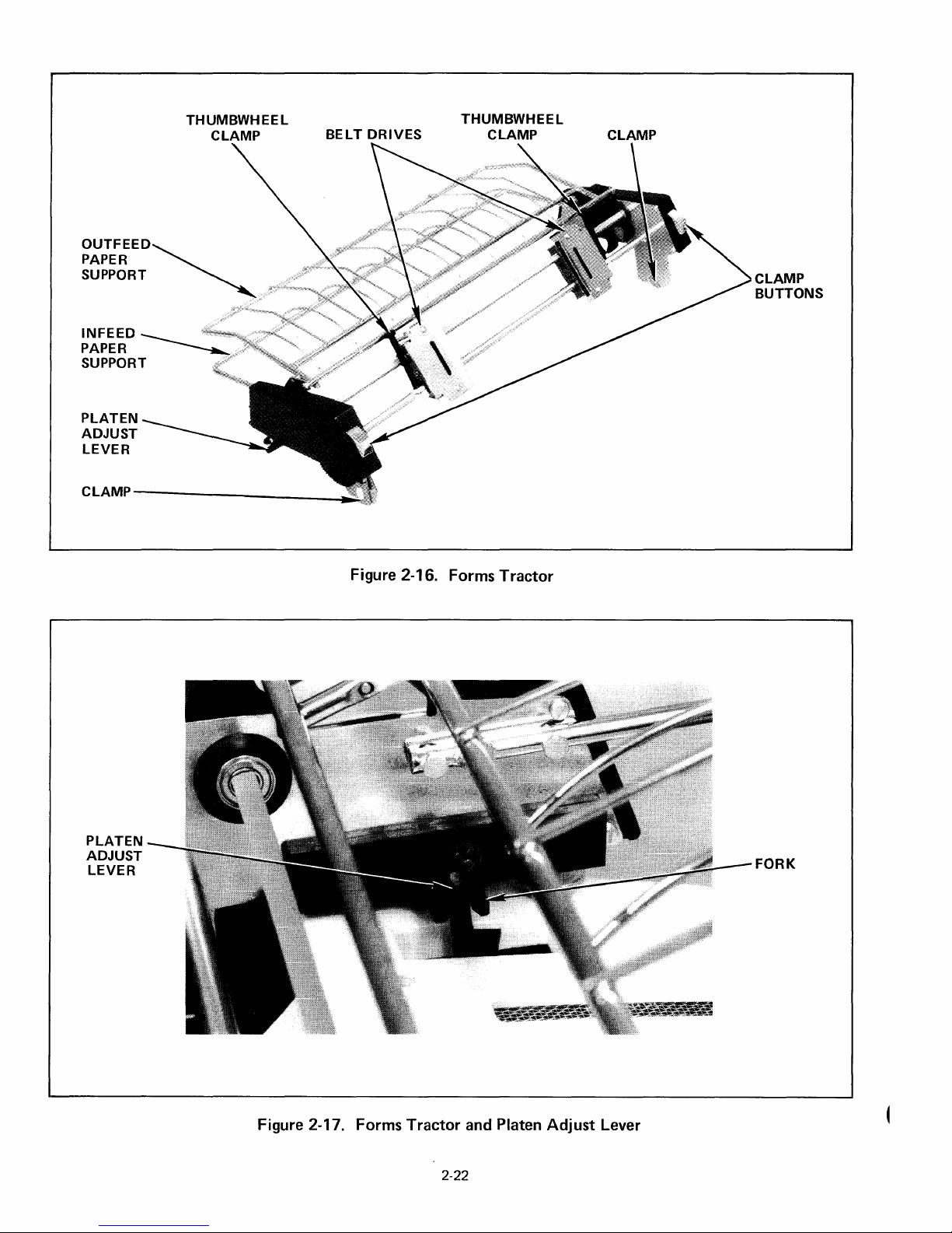
THUMBWHEEL
CLAMP
OUTFEED~
PAPER
SUPPORT
INFEED
PAPER
SUPPORT
PLATEN
ADJUST
LEVER
BELT
DRIVES
THUMBWHEEL
CLAMP
CLAMP
CLAMP
BUTTONS
CLAMP--------
PLATEN
ADJUST
LEVER
__________
~~
Figure 2-16. Forms
Tractor
FORK
Figure 2-17. Forms
Tractor
2-22
and Platen
Adjust
Lever
Page 39

OUTFEED
PAPER SUPPORT
PAPER
RELEASE LEVER
LARGE
FORK
Figure 2-18. Forms
PAPER
RELEASE
Tractor
LEVER
and Paper Release Lever (Tension Removed)
OUTFEED PAPER
SUPPORT TI L
TED
FORWARD
Figure 2-19. Forms
Tractor
and Paper Release Lever (Tension Applied)
2-23
Page 40

THUMBWHEEL
CLAMPS
PLATEN
ADJUST
LEVER
Figure 2-20 Forms
!!~
____________
Tractor
Installed
------------~BELT
DRIVES
2-24
Page 41

3.1
INTRODUCTION
SECTION 3
FUNCTIONAL
DESCRIPTION
3.3
RESET/INITIALIZATION
This section describes HyTerm
point
of
outside-looking-in
the
programmer
of
the
information
HyTerm
operation,
Maintenance Manual.
tions and
switches
operator
This section does
is
or
and
which may be
control,
contained
view.
systems
contained
and
analyst/planner,
others.
not
contain
found
Information
the
use
in
Section 2, Operating Instructions.
3.1.1 Local/Remote
Most HyTerm
Remote
mode,
cations
Local
operator,
Section 2,
HyTerm can be
and
is
the
Local and
modes.
data
link.
mode
and
it
is
this
While
in
latched
LOCAL key
is
transmitted
In
Local
the
information
Operating
controlled
control
Local
down.
Remote
functions
The
major difference
and
mode
HyTerm
mode,
In
alternately
modes.
is
pertaining
I nstructions. I n
that
is
covered in this section.
the
Remote
are identical in
all
controlled
largely by
mode
switches
operation
It
is
intended
here may be helpful
information
in
concerning
of
keyboard
received over
data
transfer
to
LOCAL key
the
key
the
primarily
although
on
Section 2
error
and
both
is
that
the
is
inhibited.
completely
this
is
contained
Remote
the
host
on
the
is
"up."
HyTerm
from
for
some
to
the
theory
of
the
indica-
control
Local
and
in
Remote
communi-
by
the
mode
the
computer,
keyboard
Pressing
between
an
of
In
in
The
HyTerm
During
operation,
ing
the
CLEAR
Clear,
the
(1) Normal
(2) Forward printing
(3) Print in black
(4) Horizontal spacing is
SPACI
Vertical spacing
(5)
All horizontal
(6)
(7) Left
outward
(8) Terminal
(9)
The
print
(10) Vertical position
move)
is
automatically
it can be re-initialized locally by depress-
pushbutton
following
NG
and
carriage moves
position (horizontal position 0)
conditions
print
mode
switch
set
tab
right margins are cleared
positions
print
buffer
on
are in
(not
Graphics)
controlled
to
6 lines per inch
stops
are cleared
is
cleared
the
printhead
is
cleared
initialized
the
control
effect:
by
to
zero (paper
the
to
to
at
power
panel.
setting
their
the
on.
After
of
the
extreme
leftmost
does
not
a
3.2 COMMUNICATIONS PRINCIPLES
In
Remote
ASCII-coded
interface
second
trallsmitted
(all one-bits) are discarded
National
chronous
character
parity
bit,
selectable
selected, incoming
transmitted
information
Interface.
Halfhalf-duplex, all
mitted.
without
received over
mode,
the
data
over its EIA RS-232-C
at
rates
of
10, 15,
(cps).
Any
of
the
or
received,
Standards I nstitute
data
transmission
code
consists
and
one
(EVEN/ODD/MARK).
parity
on
the
or
full-duplex
keyboard
During full-duplex,
being
printed -the
the
data
or
data
bit
data
link.
but
of a start
two
is
is
always a
format
HyTerm
128
upon
not
operation
data
keyboard
transmits
30,
or
120
characters
ASCII characters can be
NUL (all zero-bits) and DEL
reception.
(ANSI)
is
observed,
stop
checked
can be
is
only
bit, seven
bits.
With MARK
mark
is
both
The
convention
in
Character
for
parity,
(logic 1).
found
selectable. During
printed
data
is
data
printed
and
receives
compatible
per
American
for
asyn-
which
in Section 4,
each
data
bits, a
parity
parity
and
the
Further
and
trans-
transmitted
is
that
(11
) Form length
set
3.4 CHARACTER GENERATION
With
one
minor
exception,
and
handles all
originating
be covered
received over
mode,
they
is
remainder
not
specifically
may have originated
characters
point.
(The
shortly.)
the
data
are received
of
this
section,
noted,
exception
link
at
either
3.4.1 Two- and Three-Character
Two- and
normal printing, carriage
The
first
always
always means
different
a
three-character
character
the
ESC
that
meaning
of a two-
character.
the
following
than
the
the
same regardless
is
In
Remote
or
from
from
the
when
the
it
is
understood
the
keyboard
sequences are used
movement,
or
three-character
Reception
one
they
normally do.
HyTerm logic recognizes
of
their
the
DEL
code:
this will
mode,
the
keyboard
source
characters are
keyboard:
only.
of a character
that
the
or
the
data
in Local
I n
the
is
character
link.
Sequences
to
alter
or
paper
movement.
sequence
of
this
character
or
two
characters have
is
3-1
Page 42

FF
TO
HERE
NEGATIVE
~
VERTICAL
PRINTING
HORIZONTAL
NOT
MOVEMENT
POSSIBLE TO THE
POSITION
O.
LEFT
OF
,~
--~------~----~------,
0
O
.....
'III(r---
....
--HORIZONTAL
__
------------------------------------~
POSITIVE
1
v
NEXT
TO
HERE
FF
E
R
T
I
C
A
L
P
0
S
I
T
I
0
N
(1/48")
POSITIVE
"
ORIGIN
VERTICAL
POSITION
HORIZONTAL
MOVEMENT
(1/120")------4
MOVEMENT
••
1572 TOP
••
-------FORM
OF
(TOF)
'f
1
NOTE:
672
"MOVEMENT"
NOT
ACTUAL
ARROWS DEPICT
PAPER
MOVEMENT
CARRIAGE
DIRECTION.
MOVEMENT
RELATIVE
Figure 3-1. Printing Format Factors
3-2
TO PAPER,
AND
Page 43

3.5
PRINTING
Any
of
can be
zontal
these
is
a page
and
SPACI
can
or
sequences.
character
factors
used
to
can
"vertical
Either
NG
be
obtained
the
printed.
FORMAT
the
94
graphic
Printing
spacing
can
define
be
defined
position".
of
two
"standard"
switch
by
Vertical Motion
and
be
independently
the
specific
in
on
the
control
changing
characters
format
vertical line spacing.
motion
terms
formats
Index,
in
the
is
dependent
controlled;
desired.
of a "horizontal
can
be
panel.
Additional
the
Horizontal
using
ASCII
code
set
upon
hori-
Either
an
"index"
Any
point
on
position"
selected via
Motion
three-character
the
formats
Index
of
that
the
Note
cover (see Figure 2-4) has markings beginning
rather
spacing
scale
is
position.
(7) Line:
by a
is
equal
the
row
combination
than
1:
when
is
being used,
actually
vertical
of
to
the
line no. = (vertical
one
distance
printed
VMI x
scale
10
or
the
value
less
than
capable
characters.
1/48
inch.
Position)
VMI
on
12
characters-per-inch
pointed
The
3.5.2 Standard Formats
the
the
of
being
height
+ 1
printer
out
current
occupied
of
access
on
print
the
at
this
line
0
3.5.1 Definition
(1) Origin:
Feed
Clear).
page.
Horizontal
(2)
1/120-inch
printing a character
is 0 (no
inches).
(3) Vertical
1/48-inch
each
0,
(4)
Horizontal
1/120-inch
the
mum = 1572.
the
and
an
The
spacing),
Motion
increments
line
feed
maximum
origin.
position
first
Motion
increments
is
Position:
increments)
Minimum
of
Terms
of
the
Absolute
or
125.
Tab
print
position
Index
that
(or
when
maximum
Index
moved
negative line feed.
the
between
horizontal
(See
Figure 3-1)
print
head
after a Form
to
position
on
(HMI):
the
carriage moves
spacing). Minimum
is
125
(VMI):
by
the
horizontal
0 (or
the
first
the
(125/120=
the
number
paper
Minimum
distance
the
print
position = 0,
after
line
number
(platen)
VMI
head and
maxi-
of
of
after
HMI
1.04
of
for
(in
Standard
horizontal
inch,
a
a
Table
through
vertical spacing
spacing can be
depending
3-1
summarizes
the
SPACI
upon
NG
either
the
setting
the
switch.
is
6 lines per inch.
10
or
12
of
the
SPACING switch.
horizontal
spacing
Standard
characters
available
per
Table 3-1. SPACING Switch
SPACING Horizontal Spacing
Switch
10
12 12
is
Whenever
optional
in
listed
horizontal
Additional
indexing,
horizontal
Table
which
Chars/in Chars/line (max.)
10
the
SPACING switch
format
3-1
spacing.
formats
can override
for
can
has
the
be
the
obtained
HMI
132
158
is
repositioned
not
been
selected,
new position are used
by
utilizing variable
standard
formats.
12
10
and an
the
values
fOi
(5) Vertical Position:
increments)
first
line
on
position
(6)
Print
occupied
likened
that
line
number
= 125):
= 1).
print
= 0,
Position:
by
to a print
it
is
variable:
is
dependent
of
the
The
leftmost
position
the
vertical
between
the
maximum = 672
a single
print
maximum
page
the
horizontal
"column"
the
upon
positions
print
no.
=(horizontal
the
(the
print
number
number
position
current
origin).
the
per line
HMI
distance
(for 14-inch page).
area
character.
on
of
HMI.
print
Minimum
capable
a line
printer,
print
The
is
13
is
1573
is
position
Position)
(in
1/48
line and
This can be
positions
minimum
(when
(when
1.
+ 1
inch
vertical
of
being
except
HM
HMI
the
per
3.5.3 Optional Formats (Variable Indexing)
Either
of
the
format
special
these
vertical
operations
recommended
location
I
factors.
of
optional
SPACING switch.
3-3
escape
sequences
Changing
the
sequences. However,
does
position:
by redefining
that a Form
0
be
performed
the
VMI
SPACI
NG
format
factors,
not
it
does,
leaves
switch.
factors
and
can be altered
immediately
however, change
the
variable
Feed and an
prior
to
the
HMI
A Clear
returns
by
execution
alter
horizontal
subsequent
format
changing any
still
operation
format
factors.
Absolute
under
the
cancels
control
utilizing
of
any
Tab
format
control
to
It
the
the
of
or
is
to
Page 44

3.5.3.1
The
standard
3-character
an ASCII
the
number
move
after
HMI
The
ASCII
sequence
the
HMI
must
be
executed,
11.
and
NUL
increments,
horizontal
carriage
stopping
position
cannot
carriage
3.5.3.2
beyond
1573.
move
cannot
VARIABLE
VARIABLE
sequence
character
of
printing a character
= (ASCII
for
convenience
at
10,
DEL
and
position
at
the
beyond
HMI
HMI
ESC US
whose
increments
code
chart
the
three-character
since
cannot
maximum
is
set
this
position
last
(Example:
position
move
beyond
VMI
can be
character
print
altered
(n),
decimal
(1/120
or
- 1) x
is
reorganized
in
Table
the
VT
code
be used, so
is
125
at
1572:
will result
position
with
1560:
position
where
value is
inch)
when
spacing.
1/120
3-2.
sequence
has a
minimum
increments.
any
attempt
prior
HMI
set
with
1570.)
by
the
one
the
into
For
decimal
in
at
HMI
executing
example,
to
(n)
represents
greater
carriage will
inch
decimal
to
the
20,
value
to
ESC US
value
HMI
Maximum
move
carriage's
horizontal
carriage
set
at
the
than
set
VT
is
0
the
10,
of
3.6 CONTROL FUNCTIONS
All
codes
and
performed
presented
in
are
the
3.6.1 Control
Any
of
the
94
normally
print
affected
of
the
3.6.1.1
red,
ESC B
installed, all
occur.
amount
upper
"b"
prints
position
by
UC
ONL Y key
RED/BLACK
The
HyTerm
an ESC A
is
issued.
Printing
of
case A and B
codes
will have
reception
printing
mayor
ink remain ing
sequences
summarized
following
of
Printing
printing
and
then
to
the
of
on
is
initialized
sequence
If
red
must
no
effect.
that
in
paragraphs.
ASCII
causes
right.
This
ESC A
the
keyboard.
PRINTING
printing
is
issued.
is
selected
operations
may
not
occur,
on
the
be used.
characters,
the
or
with
cause
Table
carriage
printing
ESC
B,
(ESC
A/ESC
in
black.
To
return
a single-color
other
depending
type
face.
The
lower
functions
3-3. Details are
when
action
or
than
Note
to
received,
to
move
can
by
operation
B)
To
print
to
black, an
ribbon
ribbon lift
upon
that
case
"a"
be
one
be
in
the
the
and
The
standard
3-character
an
ASCII
the
number
for
each
maximum
sequence
character
of
increments
line feed
is
125.
VM
I = (ASCII
T
e
n
s
VMI
can
be altered
ESC RS (n)
whose
decimal value
(1/48
or
negative line feed. Minimum VMI
Refer
to
Table
3-2.
character
where
inch)
-
1)
by
the
is
the
x
executing
one
paper
1/48
Table 3-2. Decimal Values
1 2 3
SOH
VT
NAK SYN ETB
)
=
[
e
y
10
20
30
40
50
60
70
80
90
100
110
120
0
0
LF
DC4
RS US
(
2 3 4 5
<
F G H
P 0
Z
d
n 0
x
(n)
represents
greater
will move
inch
STX
FF
SP
*
>
R
\
f
p
z
the
than
is
0,
ETX
CR
!
+
?
I
S
]
g
q
{
3.6.1.2
case
to
transmitted.
are
for
4
EOT ENO
SO
CAN
"
,
6
@
J
T
A
UPPER CASE
When
the
alphabetic
their
upper
all
characters
ASCII Character
Units
5
SI
EM
#
-
7
A B
K L M
U
-
h i
r
I
s
}
ONLY
UPPER CASE
characters
case
Non-alphabetic
received over
ACK
DLE
SUB ESC
$
8 9
V
,
j
t
from
equivalents
6 7
%
C D
W X
a
""
ONLY
the
characters
the
BEL
DCl
/
k
u
switch
keyboard
before
are
data
link.
8
BS
DC2
FS
&
0
N
b c
I
v
is
on,
are
being
unaffected,
9
HT
DC3
GS
,
1
,
E
0
Y
m
w
all
lower
converted
printed
or
as
3-4
Page 45

Code(s)
Table 3-3. Control Functions
Function
Print
Carriage
Action
Platen
Other
ACK
BEL
BS
CR
DEL
ETX
ESC 1
ESC2
ESC 3
ESC 4
ESC5
ESC
6
ESC 8
ESC 9
ESCO
ESCA
ESC B
ESC D
ESC U
ESC LF
ESC
HT
ESC
VT
ESC
RS
ESC US
FF
HT
LF
NUL
SP
(n)
(n)
(n)
(n)
Sent
to
Acknowledge
Sound
Audible
Backspace
Carriage
Ignored
Synchronizes
Set
Horizontal
Clear All
Graphics
Graphics
Forward
Backward
Clear Individual
Set
Left
Set
Right
Print
in
Print
in
Negative Half- Line Feed
Half- Line
Negative Line
Absolute
Absolute
Define
Vertical
Define
Horizontal
Form
Feed
Horizontal
Feed
Line
Ignored
Space
Return
Terminal
Tab
Tab
Stops
On
Off
Print
On
Print
Margin
Margin
Red
Black
Feed
Feed
Horizontal
Vertical
Tab
Alarm
Stop
On
Tab
Stop
Tab
Tab
Motion
Motion
(normal)
Receipt
with
Index
Index
of
Host
(VMI)
ETX
(HMJ)
X
X
X
X
X
X
X X
X
X
X
X
X
X
X
X
X
X
X
X
X
X
X
X
X
X
X
X
X
3.6.2 Control
There
are several
affect
movement
functions
with
covered
3.6.2.1
print
Graphics,
3.6.2.2
carriage
following
(related
the
keyboard
Defining
Moves carriage
Moves carriage
the
previously
SPACE (SP)
mode,
moves carriage
moves carriage
BACKSPACE
of
Carriage Movement
different
movement,
printing.
to
tabbing)
function
Horizontal
in
Section
one
print
1/60
(BSI
one
print
codes
in
In
can
keys. See
Motion
3.5.3.1.
position
one
inch.
position
and
addition
addition,
also be
Section
Index
to
print
position
to
sequences
to
some
(HMI)
right.
left.
the
of
accompl
2.
has
In
backward
to
In
Backward
that
normal
these
ished
been
left. In
3-5
Print
mode,
Graphics,
3.6.2.3
AUTO
Print
3.6.2.4
ESC HT)
called
used
predetermined
is
executed,
stop.
in
that
allows
first
moves
CAR
Moves carriage
LF
switch
mode.
HORIZONTAL
Two
methods
"Normal
on
typewriters
The
other
it
does
automatic
126
print
moves carriage
carriage
RIAGE
Tab",
print
the
carriage
method,
not
positions,
1/60
RETURN
to
left
is
on.
of
tabbing
is
in
positions,
termed
require
positioning
from
one
print
inch.
(CRI
margin.
Cancels
TABBING
are possible.
similar
to
that
"tab
and
moves
to
"Absolute
prior
setting
of
the
any
other
position
Also
causes
Graphics
(HT,
the
traditional
stops"
when
the tab
the
next
of
carriage
print
to
right. In
line feed if
and
Backward
ESC 1, ESC
One
method,
system
are
set
command
sequential
Tab",
is
unique
tab
stops,
to
any
of
position.
2,
at
tab
and
the
Page 46

The
method
character
character
ESC HT initiates
Since
positions,
Graphics
3.6.2.4.1
or
remotely.
position
Horizontal
keyboard
carriage
HT be
right
move
the
sequence.
only
ing a
horizontal
carriage
Individual
to
stops
sequence.
slightly
3.6.2.4.2
the
126
stops.
Tab
with
print
Note
tabbing
positioned
will move
decimal
print
acter
possible
positions.
Absolute
sequence
alone
tabbing
finer
mode.
Normal
cleared,
Tab
Subsequent
be cleared and
carriage can be
print
command
horizontal
and
Tab
160.
Tab
or
to
seek
executed
of
the
to
the
stops
desired
Keeping in
the
first
tab
position
tab
to
tab
are cleared
If
different.
Absolute
positions
This
is
the
ASCII
position
that
to
at
the
value
position
other
direct
The
Tab
rightmost
print
the
the
than
operation
of
tabbing
employed.
executes a Normal
an
Absolute
provides
positioning
Horizontal
tab
stops
Once
(HT) can be
the
communications
the
next
with
present
can be
position
160
print
is
as follows:
position
TAB
next
stops
then
at
Graphics
See
Horizontal
positioned
without
accomplished
(HT)
with
character
desired (see Table 3-2).
this
method
left.
print
position
carriage
of
the
is
considered
NU L and DE L
tabbing
horizontal
position
to
be used
The
Tab.
positioning
requires
Tab.
commands
can
tab
no
horizontal
print
set
by
mind
positions,
(1-160)
operations
sequential
are cleared by
executing
one
mode
3.6.2.5.
an ESC
For
directly
ASCII
is
= (ASCII
executed,
be
set
at
stops
initiated
tab
stop
tab
stop
position.
first
and
that
=(horizontal
time
by
is
Tab.
directly
the
need
by
character,
whose
decimal
of
tabbing
example,
100,
code
location
to
any
position
computed
character
position,
position
then
the
preceding
to
are
set
the
automatically
an ESC 8
for
of
at
is
specified by
Horizontal
Tab
operation:
only
to
the
use
Tab
stops
either
any
print
set,
execution
from
link,
and
to
its right.
having
tab
first
execution
used,
for
an ESC
print
can
as follows:
been
the
ing
the
executing
tab
stops
formula
HMI
stop
tabbing
sequence;
operation
Using
Absolute
to
any
prior
the
and
value indicates
also
makes
with
HT 1 sequence
position
digit
1.
1.
Any
be used, making
the
first
the
completion
- 1) x
Tab
normal
of
spacing
can be
locally
position
either
causes
Should
set
to
carriage will
carriage
an ESC 1
can be
for
determin-
Position)+l
move
to
the
to
the
all
of
an ESC 2
can
of
the
setting
of
Horizontal
following it
possible
the
carriage
49,
The
leftmost
ASCII char-
126
of
HM
I
the
(HT)
an
print
set
up
of
the
the
an
the
set
the
right.
stop
tab
Tab,
first
tab
the
the
print
an
in
or
to
to
at
be
The
3-character
keyboard
or
the
position,
Absolute
3.6.2.5
the
of
a
until a Carriage
divorced
automatically
only
space
move
horizontal
the
Horizontal
the
normal
be
performed
To
Graphics,
print
ESC 4
return
Normal
backspace
instead
Graphics. Vertical
tions
Negative Line
movement,
effect
3.6.2.6
used. An ESC 5
ish
incremental
Graphics). During Backward
or
from
12
characters-per-inch,
combination
since
Tab
GRAPHICS
To
take
advantage
HyTerm
an ESC 3
While in Graphics, carriage
In
same
HMI, so if
off
insure
The
Paper
To
Forward
During
can
from
by
executing a tab,
operation.
Graphics
the
carriage
index
in
Graphics
Tabs
print
at
the
after
proper
make
position
is
performed.
will
resynchronize
tab
commands
mode.
commands
of
the
movement
are
unchanged
instead
in
Normal
FORWARD/BACKWARD
enter
Print
Forward
carriage
tab
sequence
the
communications
scale will be
the
scale
numbering
is
unchanged
be
sequence.
Return
printing:
move
mode,
amount.
always
the
position
completion
leaving Graphics via
tab
sure
before
In
Graphics
selected
Tab
Feed
mode.
Backward
sequence
mode.
in
(ESC 3, ESC 4)
of
the
placed
into
The
or
i.e.,
the
carriage.
the
only
1/60
Absolute
as in Normal
move
carriage
when
of
operation
the
carriage
the tab
I n all cases, a
tab
operate
move
horizontal
commands
(VT)
in
Graphics,
(ESC LF) cause
of
the
Print
or
Print
each
movement
can be issued
link.
Note
the
final
position
one
less
than
the
starts
at
a instead
Graphics
HyType's
HyTerm
an ESC 4
printing a character
space, carriage
space
inch
the
is
the
the
tab.
in
stops
mode,
the
and
full line (VMI)
mode
a carriage
character
Print
mode.
graphics
Graphics
The
not
tab
is
can be heavily util ized in
to
mode
remains
sequence
movement
carriage can
return,
and
backspace
instead
Horizontal
mode.
carriage
The
Graphics
is
executed
with
the
however,
carriage
index
Form
but
only
PRINT
the
this
of
However, Normal
some
resting precisely
is
executed,
same
the
ESC 4
and
positioned
subsequent
print
same as
only
amount.
Feed
Line
1/48
movement
(ESC
an ESC 6
return
printed
right
motion
is
is
or
position.
the
Feed
inch
(except
from
that
in
indicated
actual
print
capability,
by
reception
in
Graphics
is
executed.
completely
does
be
moved
or
back-
commands
the
selected
Tabs
operate
mUltiple
it will also
true
of
sequence.
after
leaving
at
a normal
before
carriage
they
do
space
1/60
(FF)
opera-
(LF)
of
paper
5/ESC
sequence
will
reestab-
also causes
during
is
reversed,
the
10
on
of
not
on
tabs
the
and
inch
and
they
6)
1.
of
a
in
is
3-6
Page 47

moving
Backspace keys
Print. Note,
return,
by being
and
eliminates
the
the
carriage
however,
and all
Graphics are
Space and Backspace
in
the
carriage
paper
to
the
and
codes
that
movement
Backward
both
used
movement
operations
left.
The
action
is
also reversed in
tabbing
functions
Print
mode.
at
the
following
are
of
the
operations,
are
If Backward
same
time,
printing,
affected.
Space
Backward
carriage
not
affected
Graphics
so
and
Print
only
1/2
If
the
line.
FORM
Feed
line. These
VMI
will
FEED
A Half-Line
1/2
line. A negative Half-Line
form
down
Graphics.
paper
movement
than
1/2
3.6.3.2
(ESC
is
set
be
(FF)
U)
two
to
one
causes
some
the
Feed
(ESC D) moves
commands
odd
increment
form
to
are
unchanged
number,
(1/48
move
up
the
in
the
total
inch) less
Note
that
change
HyTerm
received.
transmit
is
3.6.2.7
position.
the
carriage
The carriage
but
(horizontal
sound
disable
can
"extreme"
margin
characters
printed
made
continues
It
the
used.
MARGINS
9 sets
ESC
ESC 0 sets
The
new
left
margin has been
to
only
Changing
as
the
the
continue
after
there.
the
direction
by
the
HyTerm
to
print
is
the
responsibility
data
"from
right
(ESC
the
left margin
the
right
left margin
return
can
as
far
position
the
carriage passes
keyboard
past
right
CLEAR
will be
affects
only
as far as
be moved
as
the
0).
right
margin causes
or
the
right margin all
margin position (same
operation),
overprinted
of
carriage
in
Backward
characters
to
9,
ESC 0)
margin.
only
altered,
past
the
"extreme"
the
prevent
at
on
movement
in
of
the
left"
if
at
the
carriage
CR
the
new margin
margin
left
the
new
setting. It
further
which
the
characters
is
the
Print
mode:
the
same
sequence
host
computer
backward
current
codes
by
margin
audible alarm
printing.
the
position
point
printing
carriage
returns.
cause
position.
backspacing,
position
does
Printing
way
as
any
further
previously
Once
to
right
only
the
to
the
to
not
the
Execution
so
that
next
page. Initial
manually
first line
on
the
tored
will move
printing
the
amount
position
control
hand,
TOF
operated,
paper
The
depressing
code
on
code
is
3.6.3.3
The
been
negative line feeds move
VMI. Vertical
of a Form
the
print
turning
of
the
keyboard.
by
the
HyTerm
the
on
the
of
before
panel
or
if
the
to
the
expecte
Form
the
the
alphameric
transmitted
GRAPHICS
impact
covered
tabs
head
form
the
form
and
All
paper
first line
movement
the
FF,
switch).
form
size
subsequent
r4
Feed
function
FORM
in
of
Graphics
in
Section
are
Feed
(F
is
positioned
registration
platen
so
then
subsequent
so
that
exactly
of
the
in
(2) VMI,
Note
that
switch
Form
position.
FEED
switch
section
the
latter
(ESC
3, ESC 4)
mode
3.6.2.5.
the
platen
unaffected.
F)
moves
the
at
the
is
accomplished
that
the
print
depressing
any
the
next
this
if
setting
can be
of
case,
the
platen
subsequent
right
distance
page.
case are (1) vertical
and
(3)
the
platen
is
Feeds will
executed
or
by
producing
the
keyboard.
but
not
on
platen
Briefly, line feeds
1/48
inch instead
paper
first
line
head
SET
control
Form
Factors
form
size (set
is
changed
not
in
the
movement
upward
of
is
at
TOF
is
mon
Feed
to
allow
affecting
turned
and
move
locally
the
The
former.
of
the
by
the
key
i-
by
by
SET
the
by
FF
F F
has
and
one
3.6.3 Control
There
movement.
plished
is
also
accomplished
covered
3.6.3.1 LINE
one
line feed, causing
Graphics,
automatically
when
are 9
from
done
Defining
previously
A Line Feed
line (one VMI). An ESC LF
Section
the
AUTO
of
codes
Only
one
the
front
through
locally. See
the
Vertical Motion
in
FEEDS
(LF)
the
3.6.2.5.
as
a result
LF
switch
Section
Platen (Paper) Movement
and
sequences
of
these,
Form
panel switches.
these
switches,
Section
3.5.3.2.
(LF,
ESC LF, USC
code
will cause
sequence
form
to
move
A line feed
of
a Carriage
is
on.
2.)
Index
that
Feed,
(Setting
but
this
(VMt)
U,
the
form
acts
down
is
also
Return
affect
can be accom-
top-of-form
can
ESC D)
to
as a negative
one
accomplished
operation
paper
only
be
has
been
move
up
line. See
3-7
3.6.3.4
Unlike
tabbing,
Horizontal
Using
directly
other
a
an ASCII
number
DEL
number
amount
(a) vertical
character
Ultimate
to
line on
3-character
of
cannot
vertical
VERTICAL
horizontal
Absolute
Tab.
Absolute
character
1,
of
used, and (c)
position
any
of
the
sequence
the
line
be
the
second
paper
position
position
Vertical
the
page.
used.
is
TABBING
tab,
there
Tab.
Vertical
first
126
Absolute
ESC
VT
whose
on
the
The
is
line
(platen)
before
the
determined
= (ASCII
(ESC VT)
is
only
It
is
analogous
Tab,
the
form
lines
on
Vertical
(.,)
where
decimal value
form
to
be reached.
top
line
of
number
movement
VT
execution,
Vertical
Motion
by
the
character
one
method
to
can
the
page
Tab
is
initiated
the
(n)
is
equal
the
form
2,
etc.
The
is
determined
(b)
the
Index
following
- 1) x VMI
of
Absolute
be
moved
from
any
by
represents
to
the
NUL
and
is
line
actual
by
ASCII
(VM
I).
formula:
Page 48

Since page size
possible
there
to
per page, it
For
76
the
subsequent
new page.
absolute
negative
forms
print
to
are
only
the
example,
is
executed,
next
When a
vertical
direction
tractor
lines
have
more
first
is
page. Once a page
paper
forms
or
paper
3.6.4 Other
The
remain ing
sounding
overrun.
3.6.4.1
the
SOUND
is
defined
more
than
126
126
lines;
possible
if
there
are
the
paper
movement
tractor
tabs
of
should
cannot
push
jams will result.
Control
control
audible
AUDIBLE
in
or
less
than
lines
per
if
there
to
tab
beyond
66
lines per page
will be
is
or
bottom-feed
more
than
not
the
Functions
functions
alarm
and
ALARM
inches, and
126
page,
it
are less
the
positioned
boundary
in
relation
two
or
be
attempted,
paper
back
have
preventing
(BEL)
not
in
lines
per
is
possible
than
end
of
and a tab
to
is
crossed,
to
line 1
printer
three
because
down.
to
print
lines, it
page. If
to
126
the
to
line 10
of
is
lines in
Uneven
do
buffer
tab
lines
page.
line
of
all
the
used,
the
the
with
is
In
order
to
against
in
transmits
from
(1)
(2) As
(3)
(4) If
buffer
overrun,
a variety
the
Host
messages. Each message
may
the
buffer,
which
third
So
acters,
at
rupted,
link.
must
ACK
of
an ACK
print
buffer. A typical
computer
the
HyTerm
already
ETX (end
it
interprets
message.
long
as
enough
anyone
resulting
two
messages
delay
is
received
speed
up
the
different
character
transmits
is
printing
be receiving
of
the
transmits
this
no
more
to
fill
time,
data
in
are
transmission
from
throughput
ETX/ACK
configurations.
each
time
example
fixed-length,
is
ended
out
the
second.
fi
rst message)
an ACK
as a signal
than
the
highly
outstanding,
the
two
print
transfer
efficient
of
the
HyTerm.
to
buffer)
and still
sequence
The
an ETX
is
as follows:
with
an ETX.
the
first message,
As it
from
the
host
to
begin sending
messages
are
can
continue
use
the
host
next
message
guarantee
can be used
HyTerm
is
removed
79-character
withdraws
its pri
nt
computer,
the
(158
char-
outstanding
un inter-
of
the
data
computer
until
an
it
Each
time
the
audible
host
reason or
given for
ERROR
3.6.4.2
ETX, NUL, DEL)
the
printer
characters,
printed, a buffer
normally
but
not
or
after
and
link:
Printing can also be
However,
number
insure
results
alarm
computer
lamp
PREVENTING
All
data
data
link,
is
able
does
it can
observed.
DEL
codes
carriage
DEL
are always
they
of
correct
in
lower
for
other.
error
is
to
is
but
occur
These
returns,
are
when
them
to
not
not
operation
1/4
to
This
cond
not
be
stored
accept
if
at
transmitted
timefill
overall
BEL
character
second.
get
the
alarm
itions (see
illuminated.
BUFFER
printed,
data
occur
30
loaded
must
whether
in a print
it. This
is
received faster
"OVERRUN"
at
or
120
precautions
as
vertical
discarded
into
utilized
characters
always be used
in
throughput.
is
rece ived it
This
is
normally
operator's
indication
2.3.4),
from
buffer
buffer
can still
10
or
15
characters
cps if suitable
traditionally
"pad"
or
tabs,
form
when
received
the
print
to
eliminate
are
worst
case
sounds
used by
attention
is
except
OVERRUN
(memory)
can
timefill
feeds,
buffer.)
used, a sufficient
in
situations,
for
the
same as
that
(ACK,
the
keyboard
until
store
up
to
than
it
can
occur.
per
second,
precautions
include
characters
etc.
(NU L
over
the
Backward
carriage returns.
order
to
and
the
the
some
that
the
or
the
158
be
This
are
NUL
data
fully
this
3.7 MOTION
The
motion
carriageoperation
shortest
perform
feature
executing
mand
executed
motion
performing
accumulated
allowing
tion
that
throughput.
motion
be
any
page
any
not
ing
received
process
point
Reception
accumulation
executed
command
boundary
vertical
affect
min
and
paper-movement
which
path
to
each
is
to
reduce
these
immediately,
is
accumulated
other
and
the
print
will
will be
of
before
that
terminates
motion
horizontal
MINIMIZATION
imization
moves
the
individual
commands.
while
functions.
no
data
buffer
terminate
executed.
any
the
would
accumulated
motion
the
position
the
the
and
only
has arrived
to
printing
and
causes all
character
vertical
feature
print
operation.
time
Therefore,
print
will
while
Likewise,
become
and
cause
accumulation.
resolves a
commands
head
and
which
would
The
taken
by
any
buffer
not
the
if
for a period
empty,
all
motion
The
net
character
motion
is
printed.
paper
movement
accumulation
to
be
sequence
to
one
paper
result
purpose
the
printer
motion
is
empty
be
accumulated;
printer
motion
the
accumulaaccumulated
result
terminates
accumulated
Reception
and
executed;
single
via
from
of
th
com-
will
is
busy
has
been
of
time,
is
faster
across a
causes
it
does
of
the
is
in
be
to
the
to
of
3-8
Page 49
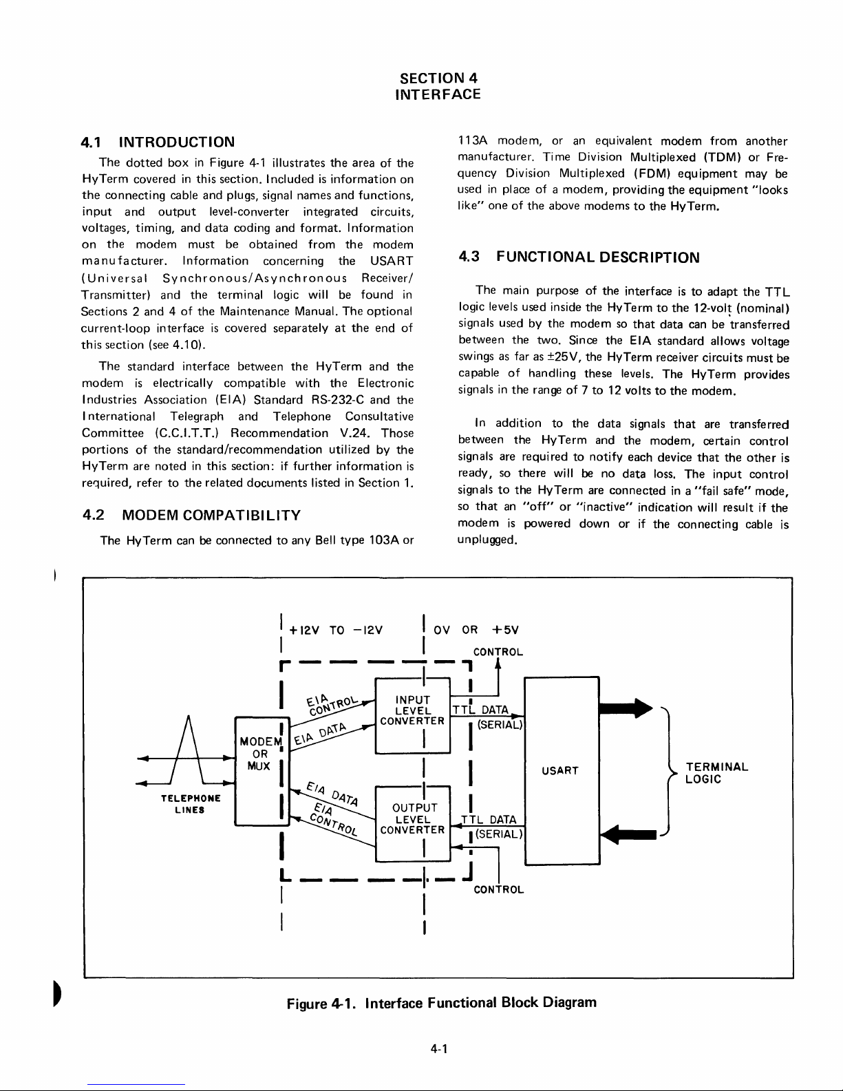
4.1 INTRODUCTION
The
dotted
HyTerm
the
connecting
input
voltages,
on
ma
(Universal
Transmitter)
Sections 2 and 4 of
current-loop
th
modem
I
I
Committee
portions
HyTerm
ret.:luired, refer
and
the
nu
fa
is
section
The
ndustries
nternational
4.2 MODEM
The
box
in
Figure
covered
timing,
modem
cturer.
standard
is
of
are
in
this
section. I ncluded
cable
and
plugs, signal
output
Synchronous/Asynchronous
and
interface
(see
electrically
Association (EIA)
(C.C.I.T.TJ
the
noted
to
level-converter
and
data
must
be
Information
the
terminal
the
Maintenance
is
covered
4.10).
interface
compatible
Telegraph
standard/recommendation
in
this
the
related
COMPATIBILITY
HyTerm
can
be
connected
4-1
illustrates
names
integrated
coding
and
format.
obtained
concerning
between
Standard
and
Recommendation
section:
documents
from
logic will be
Manual.
separately
the
HyTerm
with
RS-232-C
Telephone
if
further
listed
to
any Bell
the
area
is
information
and
functions,
Information
the
the
found
The
at
the
the
Electronic
Consultative
V.24.
utilized
information
in
Section
type 1 03A
SECTION 4
INTERFACE
of
the
on
circuits,
modem
USART
Receiver/
in
optional
end
of
and
the
and
the
Those
by
the
is
1.
or
113A
modem,
manufacturer.
quency
used
I
ike"
4.3
logic levels used inside
signals used by
between
swings as far as
capable
signals
between
signals are
ready,
signals
so
modem
unplugged.
Division MUltiplexed (FDM)
in
place
one
FUNCTIONAL
The main purpose
of
in
In
addition
so
to
that
an
is
or an
Ti me Division Multiplexed (TOM)
of a modem,
of
the
above
the
the
two.
Since
±25V,
handling
the
range
of 7 to
to
the
HyTerm
required
there
will
the
HyTerm
"off"
or
powered
equivalent
providing
modems
to
DESCRIPTION
of
the
interface
the
HyTerm
modem
the
to
so
the
the
HyTerm
these
levels.
12 volts
data
and
notify
be
no
data
are
connected
"inactive"
down
or
that
EIA
signals
the
each
modem
equipment
the
the
HyTerm.
is
to
the
data
standard
receiver
The
to
the
that
modem,
device
loss.
The
in a "fail
indication
if
the
connecting
from
another
or
Fre-
may be
equipment
to
adapt
12-volt
can
allows voltage
circuits
HyTerm provides
modem.
are
certain
that
will result if
the
(nominal)
be
'transferred
must
transferred
control
the
other
input
control
safe"
cable is
"looks
TTL
mode
th~
be
is
TELEPHONE
LINES
I
I
r
I
I
MODEM
OR
•
MUX
I
I
I
L
I
I
+12V
TO
--
-12V
I
OV
I
--,
OR
+5V
CONTROL
I I
INPUT
LEVEL
CONVERTER
I
I
I
OUTPUT
LEVEL
CONVERTER
I
---
Figure 4-1. Interface Functional Block Diagram
-I·-J
I
I
I
TTL
I
(SERIAL)
TTL
I
(SERIAL)
CONTROL
DATA
USART
DATA
TERMINAL
LOGIC
4-1
Page 50

Data
Terminal
I(H~~
2lH~~
3
4
~~----~~~~~~----
5
~~~.r~~~~~-----
6~~~"~~~=-~~~--
Read
7nH~~---=~~~~=-----
21
0 8
22
90
23g
100
24
0
110
250 120
130
Figure 4-2. Interface Connector
Table 4-1. I nterface Signals
___
P~r~o~te~c~t~iv=e~G~r=ou=n=d~_
..
~T~ra~n~sm~it~te~d~D~a~t~a
__
_
Con
nector ~ __
Pin
No.
2
3
4
5
6
7
--"C,.i.:...:rc=u:.:..:i
EIA
C.C.I.T.T.
AA
BA
BB
CA
CB
CC
AB
t:......-._---i
101
103
104
105
106
107
102
EIA
Signal Name
Protective Ground
Transm itted Data
Received Data
Request
Clear
to
to
Send
Send
Data Set Ready
Signal Ground
Function
Connected to pin 7, signal ground.
removing a jumper inside the HyTerm.
1
is
pin
left "floating."
The serial, ASCII-coded digital data being transmitted
the HyTerm. This line
characters, rises for logic
is
in
the
0 and drops for
May
"mark"
be
disconnected
When
this
is
done,
by
by
state (low) between
logic
1.
The serial, ASCII-coded digital data being received by the
HyTerm. This line must
between characters, and should
logic
1.
Goes
high
whenever power
Must
be
on (high) for HyTerrn data transmission.
data can
be
sent. (Remote mode).
Must be on (high) for HyTerm operation.
be
held
in
the
"mark"
go
high
for logic 0,
is
on.
low
If
off, no
state
for
If off, no data
can be received (Remote mode).
Ground reference for
all
other interface signals.
8
CF
109
Received Line
Signal Detector
20
23
CD
CH
108
111
Data Terminal Ready
Data
Signal Rate
Selector
Carrier Detect. Not sampled
On
(high) whenever HyTerm power
Not connected inside HyTel
future use.
4-2
by
HyTerm.
is
on.
m.
Included only for possible
Page 51
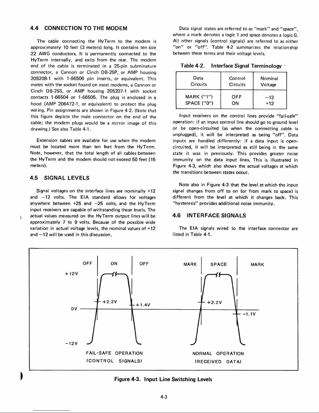
4.4 CONNECTION TO THE MODEM
The
cable
connecting
approximately
22
AWG
HyTerm
end
of
connector, a Cannon
205208-1
mates
with
Cinch DB-25S,
contacts
hood
(AMP
wiring. Pin assignments are
this
figure
cable;
the
drawing.) See also Table 4-1.
Extension
must
be located more
Note,
however,
the
HyTerm and
meters).
4.5
SIGNAL
Signal voltages
and
-12
anywhere
input
receivers are capable
actual values measured on
approximately 7 to
variation
and
-12
10
feet
conductors.
internally, and
the
cable
is
with
1-66506
the
socket
or
1-66504
depicts
modem
or
206472-1,
the
plugs
cables are available
that
the
LEVELS
on
volts.
The
between
in
actual voltage levels,
will be used
the
HyTerm
(3 meters) long. It
It
is
permanently
exits
from
terminated
or
Cinch DB-25P,
pin inserts,
found
on
most
AMP housing 205207-1 with
1-66505.
or
male
than
the
modem
the
EIA
+25
and
9 volts. Because
in
this discussion.
The
equivalent)
shown
connector
would
be a
for
ten
total
length
shou
interface lines are
standard
-25
of
withstanding
the
HyTerm
the
to
contains
connected
the
rear. The
in a 25-pin
or
or
equivalent.
modems, a Cannon
plug
is
to
protect
in
Figure 4-2. (Note
on
mirror
use
when
feet
from
of
all
Id
not
exceed
allows
volts, and
these
output
of
the
nominal values
the
modem
ten
to
modem
subminature
AMP housing
socket
enclosed
the
the
end
of
image
of
the
modem
the
HyTerm.
cables
between
50
feet
nominally
for
voltages
the
HyTerm
levels.
lines will be
possible wide
of
is
size
the
This
or
in a
plug
that
the
this
(15
+12
The
+12
Data signal
where a mark
All
other
"on"
or
between
signals
"off".
these
states
are
referred
denotes
terms
a logic 1
(control
Table 4-2 summarizes
and
and
signals) are referred
their
voltage levels.
to
as
"mark"
space
denotes
the
Table 4-2. Interface Signal Terminology ,
Data
Circuits
MARK
SPACE
Input
operation:
or
be
unplugged), it will be
inputs
circuited, it will be
state
immunity
Figure 4-3,
the
transitions
Note also
signal changes
different
"hysteresis"
4.6
The
I isted
in
("1")
("0")
receivers
if an
open-circuited
are
it
was
on
from
input
handled
in
previously.
the
which
between
in
Figure 4-3
from
the
provides
on
also
INTERFACE
EIA signals wired
Table 4-1.
Control
Circuits
the
control
control
(as
when
interpreted
differently:
interpreted
data
input
shows
states
that
off
to
level
at
additional
SIGNALS
OFF
ON
lines provide
line should go
the
if a
as still being
This
provides greater noise
lines. This
the
actual voltages at
occur.
the
level
on
(or
from
which
to
it changes back. This
noise
the
interface
Nominal
Voltage
-12
+12
to
connecting
as
being
data
input
is
at
which
mark
immunity.
and
"space",
a logic
to
as
either
relationship
"fail-safe"
ground level
cable
"off".
is
in
the
illustrated
which
the
to
space)
connector
O.
is
Data
open-
same
in
input
is
are
OFF
+12V
OV
----~~--------~~--------------------~----------~~------
-12V
FAIL-SAFE
(CONTROL
ON
OPERATION
SIGNALS)
Figure 4-3.
OFF
Input
MARK
NORMAL
(RECEIVED
Line Switching Levels
4-3
SPACE
OPERATION
DATA)
MARK
Page 52

4.7
DATA
Figure 4-4
character
lines. Voltage levels are
depending
of
the
line
the
initial
seven
data
the
parity
This figure
the
opposite
the
control
3)
parity
2)
parity
FORMAT
is
(K) on
upon
is
mark. The
transition
bits
follow,
bit,
followed
shows
level
panel
bit
is
not
bit
is
always
an idealized
the
the
baud
from
for
is
set
checked,
representation
Transmitted
nominally
rate
selected.
beginning
mark
least
significant
by
the
stop
even
parity:
odd
parity.
to
MARK,
and
mark
("
1"
/
Data
or
±12
volts.
The
of a character
to
space
(the
bit
bit(s).
the
parity
If
the
PAR
the
Received
the
Transmitted
= low).
Received
Timing
idle
start
first.
lTV
of
an ASCII
condition
is
noted
bit).
Then
bit
would
switch
Data
Data
Data
varies
by
The
comes
be
on
(pin
(pin
CODE
1\
BITS
The
illustration
both
ten-
and
eleven-bit
nous
data
transmission,
acters
can vary
more.
Generally,
the
minimum
HyTerm
acters,
depending
The
coding
data
is
the
(ASCII),
Standards I nstitute,
International
chart
showing
contained
from
character
will have
system
USA
Standard
standard
Organization
the
in
Appendix
upon
also
shows
the
characters.
the
length
this
minimum
computer-generated
spacing.
widely
the
speed
CJsed
Code
no.
X3.4-1977
and
standard
bit
configuration
A.
up
Data
varying spaces
of
for
transmitted
for
Information
of
no. ISO
for
Standardization.
\
minimum
Since
this
of
time
to
several seconds
data
generated
the
keyboard
the
American
646-1973
for
each
spacing
is
asynchro-
between
will have
between
entry.
and
received
Interchange
National
A
character
by
char-
char-
of
for
or
only
the
the
code
is
+
(SPACE)
OV.
-
(MARK)
+(SPACE)
o
v.
-(MARK)
-
A.
-
START
BIT
110
START
BIT
0
BAUD,
0
I
TWO
I
-
STOP
-
2
I
2
I
BITS.
3
0 I
-
0
-
I
STOP
BITS
-
I
I
I
4
5
0
6 7
0
P
I 0
-
I
I
I
EARLIEST
CHARACTER
4
5 6 7
POINT
MAY
AT WHICH
START.
P
NEXT
STOP
BIT
r-
---
I
I
I
I
0 0
I 0
-
I
I
I
NEXT
EARLIEST
CHARACTER MAY
POINT
AT
WHICH
START.
-.J
B.
150
OR
300
BAUD t ONE
STOP
BIT.
Figure 4-4. Data
Format
4-4
on
Interface
Page 53
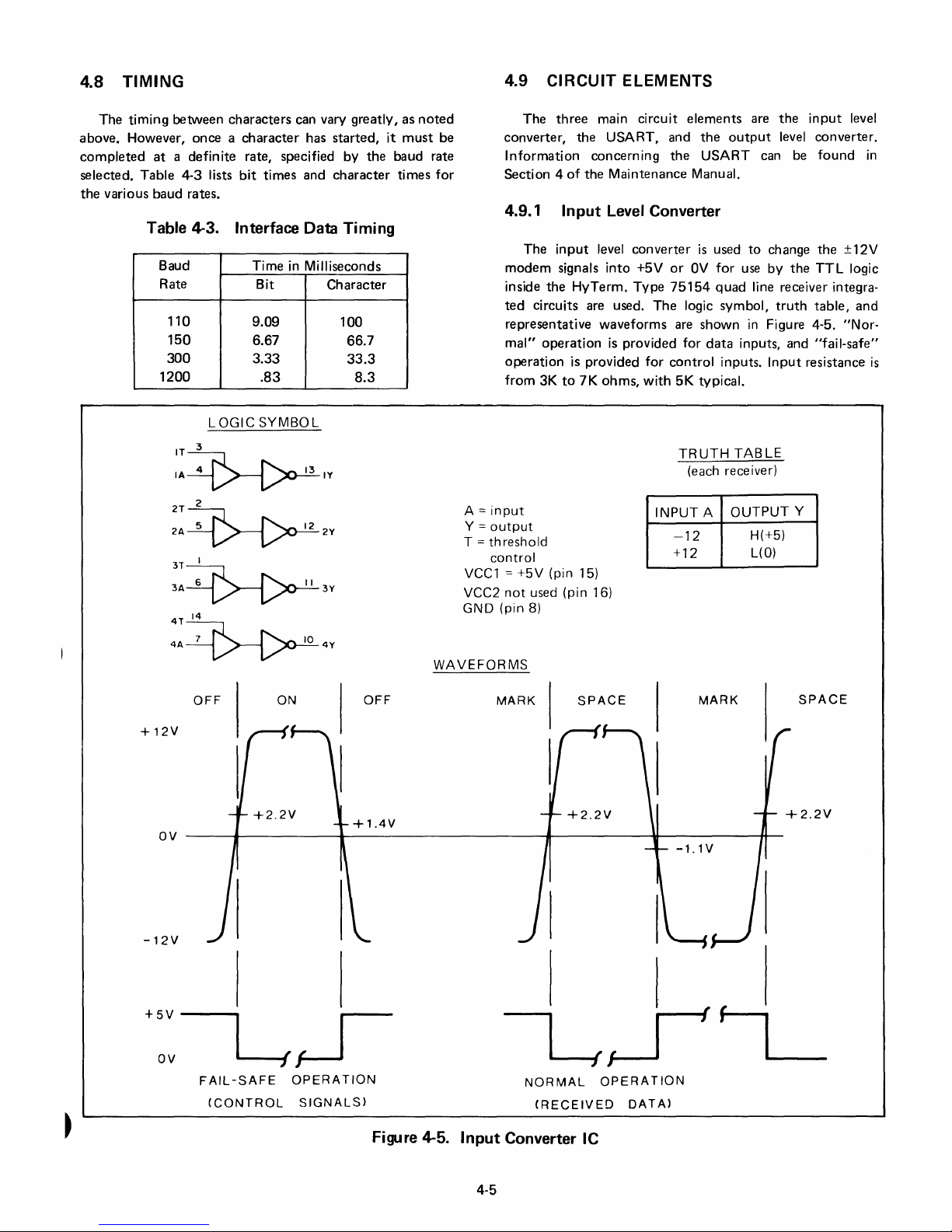
4.8
TIMING
The
timing
above.
completed
selected.
the
However,
various
between
at a definite
Table
4-3
baud
characters
once a character
rate, specified
lists
bit
times
rates.
can vary
has
started,
and
character
greatly,
by
the
Table 4-3. Interface Data Timing
Baud
Rate
110
150
300
1200
Time
Bit
9.09
6.67
3.33
.83
in
Milliseconds
Character
100
66.7
33.3
8.3
it
baud
times
as
noted
must
be
rate
for
4.9 CIRCUIT ELEMENTS
The
three
main
converter,
Information
Section 4 of
4.9.1
The
modem
inside
ted
representative
mal"
operation
from
the
Input
input
signals
the
HyTerm.
circuits are used.
operation
is
3K
to
7K
circuit
USART,
concerning
the
Maintenance
Level Converter
level
converter
into
+5V
Type
waveforms
is
provided
provided
ohms,
The
for
with
elements
and
the
the
USART
Manual.
is
or
OV
75154
logic
are
shown
for
control
5K
typical.
are
output
can be
used
to
change
for
use
by
quad
line receiver integra-
symbol,
in
Figure 4-5.
data
inputs, and
inputs.
Input
the
level
the
truth
input
level
converter.
found
the
±12V
TTL
logic
table,
and
"Nor-
"fail-safe"
resistance
in
is
IT
LOGIC
3
SYMBOL
IA~IV
2T
2
2A~2V
3T I
3A~3V
4T
14
4A~4V
OFF
+12V
OV
ON
OFF
A =
input
Y =
output
T =
threshold
control
VCC1 = +5V
not
VCC2
GND (pin
WAVEFORMS
MARK
(pin 15)
used (pin 16)
8)
SPACE
TRUTH
(each receiver)
INPUT A
-12
+12
MARK
TABLE
OUTPUT
H(+5)
L(O)
Y
SPACE
-12V
+5V----
OV
---4{~
FAIL-SAFE
(CONTROL
OPERATION
SIGNALS)
I
Figure 4-5.
Input
4-5
NORMAL
(RECEIVED
Converter IC
OPERATION
DATA)
Page 54
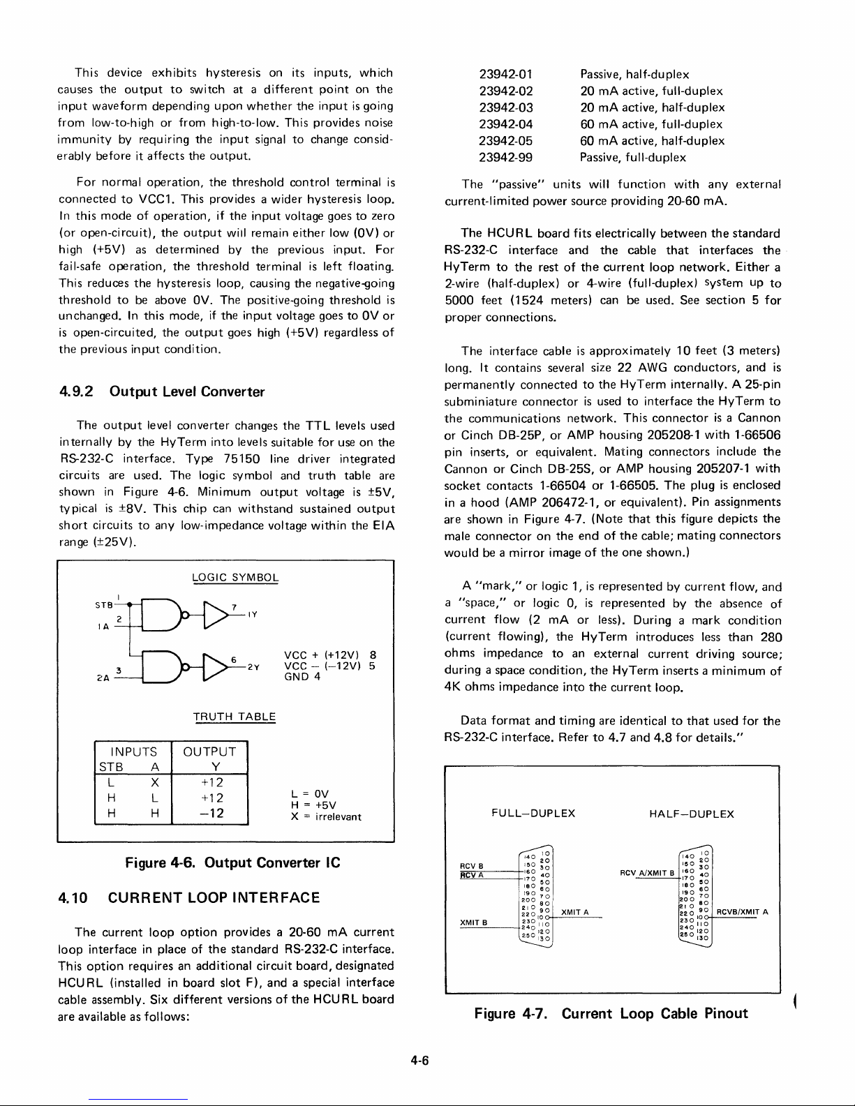
This device
causes
input
from
immunity
erably
the
waveform
low-to-high
before
For
normal
connected
In
this
mode
(or
open-circuit),
output
by requiring
it
affects
operation,
to
VCC1. This provides a
of
high (+5V) as
fail-safe
This reduces
threshold
unchanged.
is
the
4.9.2
internally
R5-232-C
operation,
the
to
be above
In
this
open-circuited,
previous
input
Output
The
output
by
the
interface.
level
circuits are used.
shown
tv
short
pical
in
Figure 4-6. Minimum
is
±8V.
circuits
to
range (±25V).
exhibits
depending
or
hysteresis
to
switch
upon
from
high-to-Iow. This provides noise
the
input
the
output.
the
on its
at a different
whether
signal
to
threshold
control
wider
operation,
the
determined
the
output
threshold
if
the
input
will remain
by
the
terminal
voltage goes
either
previous
hysteresis loop, causing
OV.
The
positive-going
mode,
if
the
input
voltage goes
the
output
goes high (+5V) regardless
condition.
Level Converter
converter
HyTerm
Type
The
This
chip
any low-impedance voltage
changes
into
levels suitable
75150
the
line
logic symbol and
output
can
withstand
inputs,
point
the
input
change consid-
terminal
hysteresis
low
input.
is
left floating.
the
negative-going
threshold
to
TTL
levels used
for
use
driver
integrated
truth
table are
voltage
sustained
within
which
on
is
going
loop.
to
zero
(OV)
OV
on
is
±5V,
output
the
EIA
the
or
For
is
or
of
the
23942-01
23942-02
23942-03
23942-04
23942-05
23942-99
is
The
"passive"
current-limited
The
HCU R L
RS-232-C
HyTerm
interface
to
the
power
board
rest
2-wire (half-duplex)
5000
feet
(1524
proper
connections.
The
interface
It
long.
permanently
subminiature
the
or
pin inserts,
Cannon
socket
in a hood
are
male
would
contains
connected
connector
communications
Cinch OB-25P,
or
equivalent.
or
Cinch OB-25S,
contacts
(AMP
shown
in
Figure 4-7.
connector
be a
on
mirror
1-66504
Passive, half-du plex
20
mA
active,
20
mA
active, half-duplex
60
mA active,
60
mA active,
Passive, full-duplex
units
will
function
source
providing
fits
electrically
and
the
cable
of
the
current
or
4-wire (full-duplex) System
meters) can be used.
cable
is
approximately
several size
network.
or
AMP housing
206472-1,
the
image
to
is
end
of
the
used
Mating
or
or
or
(Note
of
the
22
AWG
HyTerm
to
interface
This
205208-1
connectors
AMP housing
1-66505.
equivalent).
that
the
cable;
one
shown.)
full-duplex
full-duplex
half-duplex
with
any
20-60
mAo
between
that
loop
the
interfaces
network.
See
section 5 for
10
feet
(3 meters)
conductors,
internally. A 25-pin
the
HyTerm
connector
is a Cannon
with
include
205207-1
The
plug
is
Pin
assignments
this
figure
depicts
mating
connectors
external
standard
the
Either
up
to
and
to
1-66506
the
with
enclosed
the
a
is
LOGIC
TRUTH
INPUTS
STB
L X
H
H H
Figure 4-6.
A
L
OUTPUT
Y
+12
+12
-12
Output
4.10 CURRENT LOOP
The
current
loop
interface
This
option
HCU RL (installed
cable
assembly. Six
are
available as
loop
in
place
requires
follows:
option
of
an
additional
in
board
different
the
SYMBOL
IY
vee +
vee -
2Y
GND
TABLE
Converter IC
INTERFACE
provides a
standard
slot
versions
RS-232-C interface.
circuit
F),
and
of
(+12V)
(-12V)
4
L =
OV
H =
+5V
X =
irrelevant
20-60
board,
a special
the
HCURL
8
5
mA
current
designated
interface
board
A
"mark,"
a
"space,"
current
(current
ohms
impedance
during
4K
ohms
Data
RS-232-C
RCV B
RCVA
XMIT
B
or
logic 1,
or
logic 0,
flow
(2
flowing),
a space
condition,
impedance
format
and
interface.
FULL-DUPLEX
~
150
~g
160
40
170
50
180
60
190
70
200
80
210
90
220
10
~~g
110
120
~
mA
the
to
into
timing
Refer
XMIT
is
represented
is
represented
or
less). During a
HyTerm
an
external
the
HyTerm
the
current
are identical
to
4.7
RCV
A
by
by
introduces
current
inserts a
loop.
to
and
4.8
for
HALF-DUPLEX
A/XMIT
B
~
200
210
22
230
240
~
Figure 4-7. Current Loop Cable Pinout
current
the
mark
less
driving
that
details."
150
~g
160
40
:~g
~o
190
60
70
60
0
I~O
II 0
'20
flow,
absence
condition
than
source;
minimum
used
for
RCVB!XMIT
and
of
280
of
the
A
4-6
Page 55

5.1
INTRODUCTION
In
addition
this
ments.
5.2
Before
tainer,
may
the
Do
the
carrier's
section
container
not
contains
PRELIMINARY
unpacking
inspect
have
occurred
open
representative
to
the
is
obvious,
the
unpacking
information
the
container
during
container
and
installation
on
environmental
INSPECTION
HyTerm
shipment.
contact
has
for
any
and
remove
inspected
from
If
the
obvious
in-transit
carrier
it.
its
shipping
damage
immediately.
the
contents
SECTION 5
INSTALLATION
procedures,
require-
con-
that
damage
to
until
5.4 SYSTEM REQUIREMENTS
The
However,
power
requirements
HyTerm
the
may
operating
must
be easily
environment,
also
be
considered.
and
5.4.1 Operating Environment
Section
ing
altitude.
and
1.3.4
storage
shows
limits
the
minimum
for
and
temperature,
quickly
available space,
maximum
installed.
operat-
humidity,
and
and
5.3 UNPACKING
Follow
shipping
require
is
a list
instructions,
observed:
be
(1)
(2) As
(3) Remove
(4)
(5)
(6)
(7)
the
container.
slightly
of
items
as well
During
not
sories
material
unpacking,
inflict
the
HyTerm
a claim
original
Check
container
accessories
Notify
the
Cut
printer
packing
from
all
shipper
Remove
printer
four
mounts,
and
carriage
Remove
purposes.
unpacking
Different
different
that
as
damage
is
to
be filed
packing
the
if
reshipment
items
against
to
ensure
of
the
four
casting
screws
at
each
remove
any
tags,
AND
INSPECTION
instructions
configurations
unpacking
are
generally
a few general
be careful
to
the
HyTerm.
is
unpacked,
for
materials.
material
container.
as
the
any
from
holding
corner
the
to
the
and any
is
anticipated.
they
packing
that
shortages.
restraining
the
of
shipping
side
tape,
CAUTION
attached
procedures.
covered
items
that
tools
inspect
damages,
Save all
are
they
bottom.
the
the
restraint
frame.
etc.,
it
cartons
of
removed
list. Check
have been received.
bolts
threaded
(Do
casting
printer.)
put
on
of
the
in
the
that
should
being
for
save all
the
NOT
to
that
for
to
the
HyTerm
Following
specific
also
used
do
damage.
of
the
of
acces-
packing
from
the
the
list
into
remove
the
shock
secures
shipping
If
of
the
the
5.4.2
sions
x
allowed
minimum
Space
Very
of
the
width). A minimum
Width
Depth
Depth
Requirements
little
space
HyTerm,
on
all
space
requirements
(1620)
(1610)
is
sides
required
approximately
of 6 inches
for
proper
the
36
inches
26
inches
22
inches
5.4.3 Weight
KSR
RO
481bs.
431bs.
5.4.4 Power Requirements
The
Hyterm
47-63
Hz,
foot
(3.7-meterl
5.5
INSTALLATION
Installation
power
source,
tion
to
the
data
communications
and
consumes
of
initial
modem,
operates
power
the
HyTerm
start-up
and
link.
95
to
approximately
cord
is
PROCEDURES
initial
beyond
20 x 24
(15.2
ventilation,
following:
21.8
130V,
provided.
consists
and
local
verification
the
cm)
92.4
66.0
55.9
kg.
19.5
kg.
or
190
200
of
plugging it
checkout,
overall
inches
should
making
cm
cm
cm
to
watts.
of
the
dimen-
(depth
260V,
A 12-
into
connec-
remote
be
the
at
a
Do
not
attempt to
lifting
up
on
the top
and/or
on
cover.
rack.
its rear heat sink,
cover removed,
damage
the electronic
raise
the
the paper rack attached to
This
could break
Never
tilt
the HyTerm back
even
with
for
this could
circuit
boards.
HyTerm
the
cover
the
severely
by
top
5-1
During
attention
card
provided
Proper
Diablo
the
highest
installation,
be given
with
completion
Systems
standards
Diablo
Systems
to
the
Installation
all
units
shipped
and
prompt
in
its
efforts
to
of
quality
possible.
Quality
return
provide
requests
Report
from
of
lOR
the
customer
that
the
special
factory.
cards
(lOR)
aids
with
Page 56

RELEASE
LEVER
HPRO
Figure 5-1.
BOARD
Top
Cover
CI
RCUIT BOARD CLAMP
Release
Lever
Figure 5-2. HPRO Board Location
5-2
Page 57
5.5.1
as
receptacle.
reach
must
many
systems,
each
paper
normal
top-feed
the
the
time.
before
verified. If
these
Section
(1)
(2) Make sure
Initial
The
HyTerm
the
ac
power
Position
a su
itable
On
HyTerms
be
added
different
the
individual
Bottom-feed
cradle
bottom-feed
paper
platen
(see
platen
and
Do
not
connect
The
HyTerm
the
procedures,
2.3.4.
Set
the
capability
Start-up and Checkout
is
ready
for
Local
cord
is
plugged
the
wall
factory
to
styles
installer
situation.
HyTerms
not
installed.
use.
2.4.3.1
access
any
trouble
POWER
the
outlet.
the
stub
of
must
operation.
To
install, raise
),
cover.
the
should
for
refer
to
switch
printer
HyTerm
wired
and
E I A
is
so
Do
not
for
end
of
plugs
are used in
obtain
are
shipped
This
cradle
lay
the
or
current
be
started
the
Remote
encountered
the
Error
to
the
access
Mode
into
that
use an
220V
the
a plug
must
It
may
the
access cover,
cradle
up
and
Recovery
OFF
cover
operation
the
facil ity
its
power
exten
operation,
power
220V
suitable
with
the
be left
be
installed
in place.
loop
cable
checked
Mode
operation
while
procedures
position.
is
closed.
as
soon
power
cord
will
sion
cord.
a plug
cord.
Since
power
for
use in
top-feed
out
remove
Replace
at
th
locally
performing
for
for
in
board.
The
HyTerm
versions
functionally
addition,
different
installation
26
accomplished
jumper.
socket
a small
plugged
cutting a jumper.
(1) Make sure
is
(2)
is
(3)
(4)
AWG
To
wall.
Remove
inside
cover
of
different
jumper
requires
wire
Later
for
installation
shorting
into
access
Remove
Remove
platen
safely aside.
this
alike,
the
the
the
(Fi gure
may
come
board,
but
jumper
revision levels
installation
soldering a 1/2-inch
to
the
by
unsoldering
revision
the
the
the
plug,
board
HPRO
the
forms
platen
printer
cover
boards
of
the
Diablo
or
board,
power
tractor
(2.4.3.1).
at
5-1),
equipped
HPRO 1 or
locations
techniques.
board.
pulled
top
Jumper
or
are
equipped
1200
part
out,
use
the
cord
is
if
one
cover: release
both
sides,
and
lift
with
HPR02.
are
of
these
(1.2
removal
simply
baud
disconnected
by
with a miniature
jumper;
no.
10634,
instead
following
is
installed.
the
just
in
the
cover
either
Both
different.
boards
Most
cm)
cutting
in
is
of
soldering
procedure:
from
two
front
off.
of
requ ire
jumper
length
can
this
simply
latches
of
Set
two
are
In
of
be
the
case
or
the
the
the
(3) Plug
(4)
(5)
(6)
the
receptacle
HyTerm
is
indicated
hitting
about
Depress
Insert
on
from
depress
The
cover.
Operate
print
small
adjustment
shipment.
handling
factory.
the
1/5
the
a piece
the
keyboard
its Clear
the
HyTerm
or
percentage
ac
power
and
set
should
by
the
left
mechanical
inch
to
LOCAL
of
position.
Clear
should
all
keys
perform
to
obtain
This
is
conditions
cord
the
Clear
when
carriage
the
right
key.
paper
until
pushbutton
Clear
in
Local
their
of
terminals
due
to
after
into
POWER
power
moving
stop,
then
and
stopping.
in
the
printer.
the
carriage
Raise
the
on
again. Close
mode
function
may
optimum
uncontrollable
the
units
the
switch
to
properly.
print
5.5.2 Jumper Installation/Removal
It
may
be
another
All
necessary
jumpers
to
are
install
one
contained
jumper
on
is
applied.
leftward
moving
Type
is
access
the
verify
require
and/or
the
facil ity
to
as
some
cover
control
the
that
quality
shipping
have
HPRO
power
ON.
A Clear
slowly,
quickly
desired
distance
panel.
access
they
Note:
printer
after
and
left
remove
circuit
The
and
A
the
Some HyTerms have the control panel
switch assembly
cover.
If
this is the
damage the connecting cable
is
set
aside.
(5) Using a Phillips
clamp
by
loosening
Figure 5-2.
(6)
5.5.2.1
If
shorting
mode,
switch
Locate
front
Remove
reinstalling
completed,
slot -note
between
1200
plug
1200
on
the
board
1200
baud
the
HPRO
(closest
the
this
be
the
HPRO
BAUD
operation
as
shown
baud
control
CAUTION
screwdriver,
the
board.
board
by
board,
certain
that
there
board
in
is
the
panel
mounted
case,
single
to
the
pulling
after
to
plug
and
is
required,
Figure
only
speed
has
no
to
be careful
as
remove
screw
See
Figure
platen)
it
straight
the
it
back
may
be
the
next
5-3
and
available;
effect.
the top
not
the cover
the
circuit
in
the
5-2. It
on
the
jumper
into
one
empty
board.)
install a
Table
to
center.
left
up.
(When
work
the
jumper
5-1.
the
SPEED
board
See
is
the
side.
front
slot
In
this
is
or
5-3
Page 58

01
.b:.
.-
F
o
J1
INSTALLJUMPER
FOR
1200
BAUD
ONLY
OPERATION
£
u
B\~~~~~t
~4-~
>~76M22'
Pj
HPR01
f;
E36
~
F~D5
l
~5
020
~f~~~3~~
A
REMOVE JUMPER FOR
SEPARATE GROUNDS
INSTALL
PLUG NO. 10634
FOR
1200BAUD
ONLY
OPERATION
'-
REV. D OR
EARLIER
F
F2
E
o
J1
~tf154E7
P
J3
HPR01
~~.
E36
~
t D5 I
~t~~:o~
.••..
11:>
034
.I~
~
-fQill-
HPR01
Board
•
O,.==".~.'".':.,.'".'i
.....
,.'i
... ' ..
,'i
..
'·i.· ; ..••.
J
•••
~"~!
........
2
A~l
REMOVE JUMPER FOR
SEPARATE GROUNDS
INSTALL
JUMPER FOR
1200
BAUD
ON L Y
OPE
RATION
---~-~
~~~f
..•..
mao
··Jt[
J2
J3
HPR02
ASSY
NQ.
23704-[
-: J
R~
[_~
+
INSTALL
PLUG NO. 10634
FOR 1200
BAUD
ONLY
OPERATION
'--
REV. B
OR
EARLIER
r REV. C
OR
LATER
HPR02
ASSY
No.-23704-[]J
REV
[:
J
...
B
~'.'.
~5
····I~~,~>
82~11"F
~,
I.A~
··~t'G
HPR02
Board
Figure 5-3. Jumper Location
Page 59

5.5.2.2
Protective
to
jumper
HPR02
this
(Protective
GROUND DISCONNECT
Some
modems
Ground
be
disconnected. If this
F3
on
board. See Figure 5-3
jumper
Ground)
require
(pin 1) lines in
the
leaves pin 1
floating.
HPR01
the
board,
of
Signal
Ground
the
interface
is
necessary,
or
jumper
and
Table 5-1. Removal
the
interface
(pin 7) and
connector
cut
or remove
A4
connector
on
the
of
5.5.2.3 Current Loop
Several versions
interface
networks.
board
refer
Figure 5-4 shows
HyTerm
networks.
the
from
to
schematic
to
Should
one
of
the
HyTerm
it be necessary
type
of
drawing no.
the
several
HCU R L
to
different
current
proper
different
board
types
to
convert
loop
operation
23942-XX
method
types
are provided
of
current
an
to
for
instructions.
of
connecting
of
current-loop
to
loop
HCU R L
another,
the
5.5.3 E I A Cable Connection and Remote
Checkout
After
the
been
installation
completed,
the
procedures
EIA
or
current
of
Section 5.5.1 have
loop
cable
may
be
connected.
modem
no
case
the
HyTerm
Use
the
(1)
(2)
(3) Establish a
5.6
To
materials may be reused, such as
individual
type
shipment
carriage
new
EIA
extension
be located
should
following procedure:
Plug
that
sure
to
tighten
make sure
Connect
the
instructions
used.
to
Operating
trouble
Recovery.
the
and
the
cable
the
they
ac
is
encountered,
more
the
the
power
remote
cables are available should
than
combined
modem
into
the
plug
is
firmly seated; use a screwdriver
screws. If cable
are fastened securelv.
to
the
contained
data
Instructions, Section
REPACKAGING FOR SHIPMENT
repackage a HyTerm, some of
containers
cardboard
if
the cushioning qualities are gone. Also,
must
be secured
8"
nylon tie, Diablo
for accessories. However, accordian-
fillers may
to
part
ten
feet
from
the
length of all cables
exceed
modem
refer
the
50
feet
data
receptacle. Make
extensions
modem
communications
the
not
no.
in
with
the
to
Section
the
main
be suitable
printer
side frame using a
10967-02
accordance
2.3.3.
original packing
container
modem
or
the
HyTerm.
(15 meters).
link. Refer
2.3.4,
after
equivalent.
In
between
are used,
with
being
If any
Error
and
the
one
the
1200
GND
Use
Option
Baud
Disconnect
26
AWG
Table 5-1. Jumper/Shorting Plug Location
HPR01
Rev. 0
or
Earl ier
Jumper
wire for jumpers; use Diablo
F17 Plug
Jumper
F3
Circuit
Rev. E
Or
Later Earl ier or Later
F23
part
No.
Board
10634
Rev. B or
Jumper
for plug.
HPR02
82
Jumper
Rev. C
Plug B2
A4
5-5
Page 60

CURRENT
SOURCE
CURRENT
SOURCE
HOST
HYTERM
(ACTIVE)
16
17
24
2'0
140
0
0
0
0
0
o 0
0
'
'30
10
0
0
0
0
0
0
0
~
RED
WHT
GRN
ORN
01 014
o 0
o 16
o 17
~
0
o 0
o 0
r-------------------------r---------tb----------~OO
o 0
~
01302'
0
24
(PASSIVE)
140
10
o 0
,.
0
17 0
o 0
o 0
o 0
o 0
o 0
O'~~--------~--~
24
~
250
'30
CURRENT
SOURCE
CURRENT
SOURCE
CURRENT
I
TRANSMITTER
I I
-1
SOURCE
(PASSIVE)
CURRENT
OETECTOR
1
.----+-------1
l
I
FULL
-DUPLEX
HALF-DUPLEX
f
'-
>
(PASSIVE)
01 014
Ito
~"
00
o 0
013
02'
140
17
250
0
0
0
0
0
0
o 0
0'
o 0
10
0
0
0
WHT
0
0
0
0
GRN
'3~
(ACTIVE)
~
~
0
o 0
o 7
o 0
o 0
o 0
o 0
0
0
o 0
o 0
025
013
c:---
332-001
Figure 5-4. Current Loop Connections
5-6
Page 61

APPENDIX A
1977
ASCII:
Bits
~~
b3 b2
t t t
0000
0001
0010
001
0100
o 1 0 1
o 1 1 0
o 1
1000
100
1 0 1 0
101
1
1
1
1
1 1
100
101
1 1
1 1 1
American Standard Code
National Standards
b
b.
1
1
1
0
---+
7
b
---+
6
b
---+
s
rnl
tROwt
10
11
12
13
14
15
0
1
2
3
4
5
6
7
8
9
0
0
__
0
NUL
50H
5TX
ETX
EOT
ENQ
ACK
BEL
IS
HT
LF
VT : E5C
FF
-
f-
CR
50
51
Institute.
0
i
1
ASCII CODE
for I nformation
0
0
0
1
1 2
DLE
DCl
DC2
DC3
DC4
NAK
SYN
ETI
CAN
EM
SUB
FS
GS
--
RS
US
1
SP
I
•
..
#
$
0/0
&
(
)
*
+
-
"-_
..
-
•
/
CHART
I nterchange. Standard No. X3.4-1977
0
1
1
1 0
0
1
3
0
1
2
3
4
5
I
6
I
0
4
@)
A
B R
C
D T
E U
F V
,
I
7 G W
,
8
9
•
•
•
,
< L
-
-
>
H X
i
I
J
K
M
--~---
N
I
I
j
,
•
0
-
of
the American
1
1
0
0
1
1
1
5 6 7
,
P
<i
\<
.....
<.,
<
.......
•
.•
~
I
.....
I
111
t
fi
i
.
I
h
•
I
•
J
k
I
In
..
I
.>
•.
!)<
Ii
(
II
¥
W
X
Y
z
{
""
....
DEL
Q
5
Y
Z
[
\
]
"
.-
Ii
..
....
....•
•
I
}
1
..••••..
..
characters in these
non-printing.
but
prints
~
keyboard in Local mode. (Logical
place
,
of
DEL
logical
characters received
two
columns and
(Delete) does
NOT
symbol
with
not
parity
print
(,)
NOT
All
"
SP
(Space)
in Remote mode,
when entered on
is
also
_ or framing error.)
are
printed
in
When UPPER CASE ON L Y
characters (columns 6 & 7)
their
upper
case
equivalents (columns 4 & 5) before being
printed
when certain European keyboards
keyboard layouts.
A-1
or
transmitted.
Additional
is
used, shaded lower
from
keyboard
characters
are
are
converted
are
converted
used. Refer
case
to
to
Page 62

KEYBOARD
APPENDIX
LAYOUTS
B
AND
CODE
CHARTS
46-KEY
(Available with or
Position Numbers above key
code chart
referenced below key
These legends are
100% compatible printwheels:
TYPEWRITER
without
table. Control codes and special symbols
tops
identify
not
engraved on key tops.
PAIRING
10-key numeric pad.)
tops
38100
38107 Courier
38101 Pica 10
38102 Elite
KEYBOARD
refer
to
"CTR
L" mode
Courier 10
12
accompanying
72
output.
8-0
Page 63

APPENDIX
KEYBOARD
B (Continued)
LAYOUTS
AND
CODE
CHARTS
KEY
POSITION
1
2
3
4
5
6
7
8
9
10
11
12
13*
14
15
16*
17
18
19
20
21
22
23
24
25
26
27
28
29
30
31*
32
33
34
35
36
37
38
39
40
41
42
43
44
45
46*
47
48
49
50
51
52
53
54
55
56
57
58*
59
60
61
62
63*
64
65
66
67
68
69
70
71
72
73
74
75
76
77*
78
79
UNSHIFTED
MODE
NUL
ESC
1
2
3
4
5
6
7
8
9
0
- 2D
=
,
BS
NUL
HT
q
w
e
r
t
y
u
i
0
p
[
\
LF
CTRL
LOCK
a
s
d
f
g
h
j 6A
k 6B
1 6C
,
{
CR
CTRL
Function
SHIFT
z
x
c
v
b
n
rn
/
SHIFT
NUL
DEL
SP
7
8
9
4
5
6
1
2
3
0
-
EOT
SP
HT
46-Key Typewriter
ASCII
CODE
(HEXADECIMAL)
00
IB
31
32
33
34
35
36
37
38
39
30
3D
60
08
00
09
71
77
65
72
74
79
75
69
6F
70
5B
5C
OA
61
73
64
66
67
68
3B
27
7B
OD
7A
78
63
76
62
6E
6D
2C
2E
2F
00
7F
20
37
38
39
34
35
36
31
32
33
30
2E
2D
04
20
2C
09
SHIFTED
MODE
Pairing
ASCII
CODE
NUL
ESC
!
@
II
$
%
A
&
*
(
)
:;:
-
BS
NUL
HT
Q
W
E
R
T
Y
U
I
0
P
1
LF
A
S
D
F
G
H
J
K
L 4C
:
"
}
CR
Z
X
C
V
B
N
M
<
>
? 3F
NUL
DEL
SP
7
8
9
4 34 4
5 35 5
6
1 31 1
2
3 33
0
-
EOT
SP
HT
00
IB
21
40
23
24
25
5E
26
2A
28
29
5F
2B
7E
08
00
09
51
57
45
52
54
59
55
49
4F
50
5D
7C
OA
41
53
44
46
47
48
4A
4B
3A
22
7D
OD
SA
58
43
56
42
4E
4D
3C
3E
00
7F
20
37 7
38
39 9
36
32 2
30
2E
2D
04
20
2C
09
CONTROL
MODE
NUL
ESC
NUL
NUL
NUL
NUL
NUL
NUL
NUL
NUL
{
}
US
RS
GS
BS
NUL
HT
DC1
ETB
ENQ
DC2
DC4
EM
NAK
HT
SI
DLE
ESC
FS
LF
SOH
DC3
EOT
ACK
BEL
BS
LF
VT
FF
,
GS
CR
SUB
CAN
ETX
SYN
STX
SO
CR
/
NUL
DEL
SP
8
6
3
0
-
EOT
SP
HT
ASCII
CODE
00
IB
00
00
00
00
00
00
00
00
7B
7D
1F
IE
ID
08
00
09
11
17
05
12
14
19
15
09
OF
10
1B
1C
OA
01
13
04
06
07
08
OA
OB
OC
3B
27
ID
OD
1A
18
03
16
02
OE
OD
2C
2E
2F
00
7F
20
37
38
39
34
35
36
31
32
33
30
2E
2D
04
20
2C
09
*Uenotes
Repeat
Keys
8-1
Page 64

APPENDIX B (Cont'd.)
KEYBOARD LAYOUTS AND CODE CHARTS
47-KEY LOGICAL BIT PAIRING KEYBOARD
Position numbers above key tops refer
chart
code
referenced
These legends are
1000A,
compatible printwheel
2 J 4 S 6 7 8 9 I
EJCDwrnmOO(I)GJrnrnw[Jm~
ESC
I 2 J 4 S 6 7 8 9 0 US
G
B8~A~~~~Q~~mm~8000
(TIlL
(
~
Lb
HT
DCI
LOCK
49~
(SHIFT
J ) m m
__________
m
~
ETB
[NO
50
W
51
W
IT]
~S~UB~
~CA_N
____
table. Control codes and special symbols
be
ttJ
DC2
Sl
W
ET_X
____
low key
dJ
DC4
53
~
SY_N
tops
identify
not
engraved on key tops.
s:
38100
38107
38101 Pica
38102
~
L!J
EM
W!>4
~5
m
____
ST_X-=6J~S_O
SP
LfJ
NAI<
HT
!>5
~r
56
:,.
~ ~
____
C_R
________
to
"CT
R
Lit
Courier 10
Courier 72
10
Elite 12
II
I
efJ
m
51
57
~
58
IT]
CJ
~J
accompanying
mode
output.
14
RS
~
NUL
~
CD
(
cD
60?s
DLE
: 59
/
15
FS
(JI~~~~)
ESC
IF
RE:~::
(SHIFT)
)
64
65
16
~:A~
00@J
B5
67
66
&8
69
8]CB0
EJ
@J
0 G
(~D_El--~7~J
SP
~
~
8-2
Page 65
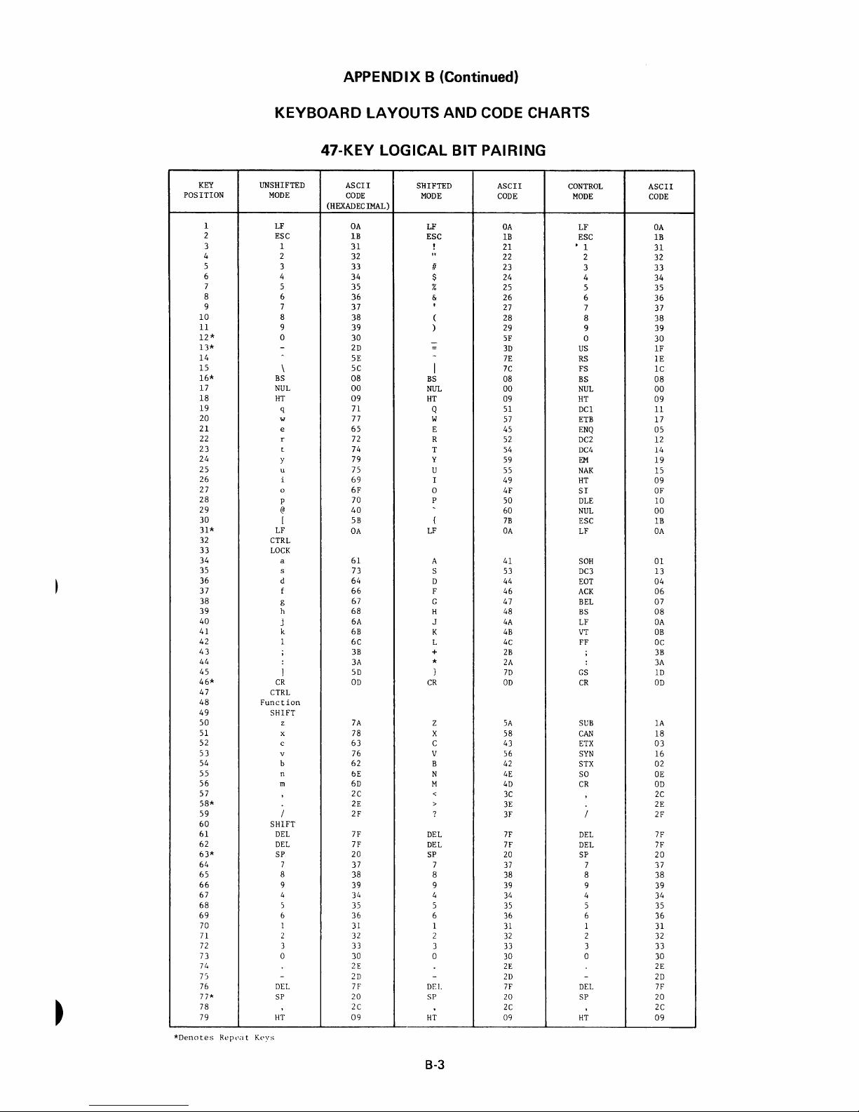
APPENDIX B (Continued)
KEYBOARD
KEY
POSITION
1
2
3
4 2
5
6
7
8 6
9 7
10
11
12*
13*
14
15
16*
17
18
19
20
21
22 r
23
24
25
26
27
28
29
30
31*
32
33
34
35 s
36
37
38
39
40
41 k
42
43
44
45
46*
47
48
49
50
51 x
52
53
54
55
56
57
58*
59
60
61
62
63*
64 7
65
66
67 4
68
69
70 1 31
71
72
73
74
75
76
77*
78
79
*Denotes
Repl'ilt
UNSHIFTED
MODE
LF
ESC
1
3
4
5
8
9
0
-
\
BS
NUL
HT
q
w
e
t
y
u 75
i
0
P
@
[
LF
CTRL
LOCK
a 61
d 64
f
g 67
h
j
1 6C
;
:
1
CR
CTRL
Function
SHIFT
z
c
v
b 62
n
In
/
SHIFT
DEL
DEL
SP 20
8
9
5
6
2 32 2
3
0 30
-
DEL
SP
HT
KC'ys
LAYOUTS AND CODE CHARTS
47-KEY
(HEXADECIMAL)
LOGICAL
ASCII
CODE
OA
IB
31
32
33
34
35
36
37
38
39
30
2D
5E
5C
08
00
09
71 Q
77
65
72 R
74
79
69
6F
70
40
5B
OA
73
66
68
6A
6B
3B
3A
5D
OD
7A
78 X
63
76 V
bE
6D
2C
2E
2F
7F
7F
37
38 8
39
34 4
35 5 35
36 6 36
33
2E
2D
71'
20
2C
09
SHIFTED
MODE
LF
ESC
!
"
II
$
% 25
& 26
I
(
)
-
=
-
I
BS
NUL
HT
W
E 45
T 54
Y
U 55
I 49
0
P
{
LF
A 41
S
D 44
F
G 47
H 48
J
K
L
+
*
}
CR
Z
C 43
B 42
N
M
<
>
?
DEL
DEL
SP
7
9 39 9
1
3
0 30 0 30
-
DEL
SP
HT
BIT
PAIRING
ASCII
CODE
OA
IB
21
22
23
24
27
28
29
5F
3D
7E
7C
08
00
09
51
57
52
59
4F
50
60
7B
OA
53
46
4A
4B
4C
2B
2A
7D
OD
SA
58
56
4E
4D
3C
3E
3F
7F
7F
20 SP
37
38 8
34 4 34
31
32
33
2E
2D
7F
20
2C
09
CONTROL
MODE
LF
ESC
• 1
2
3
4
5
6
7 37
8
9
0
US
RS
FS
BS
NUL
HT
DCl 11
ETB
ENQ
DC2
DC4
EM
NAK
HT
SI
DLE
NUL
ESC
LF
SOH
DC3
EOT
ACK
BEL
BS
LF
VT
FF
;
:
GS
CR
SUB
CAN
ETX
SYN
STX
SO
CR
/
DEL
DEL
7 37
5 35
6 36
1 31
2 32
3 33
-
DEL
SP
HT
ASCII
CODE
OA
IB
31
32
33
34
35
36
38
39
30
IF
IE
lC
08
00
09
17
05
12
14
19
15
09
OF
10
00
IB
OA
01
13
04
06
07
08
OA
OB
OC
3B
3A
ID
OD
lA
18
03
16
02
OE
OD
2C
2E
2F
7F
7F
20
38
39
2E
2D
71'
20
2C
09
B-3
Page 66

APPENDIX B (Cont'd.)
KEYBOARD
LAYOUTS
FRENCH QWERTY
AND
CODE CHARTS
Position Numbers above
code
chart
table. Control codes and special symbols
referenced below key
These legends are
100% compatible printwheels:
8dJm~ctJrnrnmdJrnc@cD8m~
ESC
18
I
~
2
20 3 21 4 22 5 23 6 24
G
32
88m~~~~~~rn~m~m(RET~N)000
(
L--
_____
lliJ
HT
33
DC1
49
(SHIFT)
00
ETB35
34
SO"
rs1;'I;-,
) W
---'S=U;:c.B
~
EN~6
DC> " ED',.
00
--.
CAN
00
DC~7
'"
~
ETX
not
(!) m
DC438
53
BEL
54.5 "LF
~
EID
SYN
STX
I (
key
tops refer
tops
identify
engraved on key tops.
7 25 8
rnJ
EM39
NA'40
~
so
6:
p
"CTR
38131 French Prestige Cubic
26 9 27 0 28
m
lli)
HT
41
,."
57
rw
CD
CR
, •
to
accompanying
L" mode
eID
51
42
DLE43
FF
58
0 8 (
US
e
,.
output.
29
RS
crJ
ES~4
Y
60
30
rn
FS
NUL
[SHIFT)
) I I (--sp
GS
31
BS
(
~~~~
LF46
CR
62
) 8
DEL
)
4~
70
71
72
73
74 75
@]
8 G
~77)
G 8
8-4
Page 67

KEY
POSITION
10
11
12*
13*
15
17
*Denotes
1
2
3
4
5
6
7
8
9
14
16*
18
19
20
21
22
23
24
25
26
27
28
29
30
31*
32
33
34
35
36
37
38
39
40
41
42
43
44
45
46*
47
48
49
50
51
52
53
54
55
56
57
58*
59
60
61
62
63*
64
65
66
67
68
69
70
71
72
71
74
75
76
77*
78
79
Repeat
APPENDIX B (Continued)
KEYBOARD
LAYOUTS
FRENCH QWERTY
UNSHIFTED
MODE
NUL
ESC
1
2
3
4
5
6
7
8
9
0
,
<
BS
NUL
HT
q
w
e
r
t 74
y 79
u
i
0
P
11
&
LF
CTRL
LOCK
a 61
s
d
f
g
h
j 6A J
k
1
e
U
CR
CTRL
Function
SHIFT
z
x
c
v
b
n
m
-
SHIFT
NUL
DEL
SP
7 37
8
9
4
5 35
b
1
2
l
0
-
EOT
SP
IlT
Keys
ASCII
CODE
(HEXADECIMAL)
00
lB
31
32
33
34
35
36
37
38
39
30
27
5E
3C
08
00
09
71
77 W
65
72
75
69
6F
70
40
26
OA
73
64
66
67
68
6B
6C
7B
7C
60
aD
7A
78
63
76
62
6E
6D
2C
2E :
2D
00
7F
20
38
39
34
36
31
32
33
30
21:
2D
04
20
2C
09
AND
SHIFTED
MODE
NUL
ESC
!
"
§
$
%
+
I
(
)
=
?
-
>
BS
NUL
HT
Q
E
R
T
y
U
I
0
P
c;
*
LF
A
S
D
F
G
H
K
L
e
0
£
CR
Z
X
C
V
B
N
M
;
-
NUL
DEL
SP
7 37
8
9
I,
5
6
1
2
3
0
-
EOT
SP
IlT
CODE CHARTS
ASCII
CODE
00
IB
21
22
5D
24
25
2B
2F
28
29
3D 0
3F
7E RS
3E
08
00
09
51
57
45
52
54
59
55
49
4F
50
5C
2A
OA
41
53
44
46
47
48
4A
4B
4C
7D
5B
23
OD
5A
58
43
56
42
4E
4D
3B
3A
SF
00
7F
20
38
39
14
15
36
31
32
33
30
2E
2D
01,
20
2C
09
CONTROL
MODE
NUL
ESC
1
2
3
4
5
6
7
8
9
US
GS
BS
NUL
HT
DC1
ETB
ENQ
DC2
DC4
EM
NAK
HT
SI
DLE
ESC
FS
LF
SOH
DC3
EOT
ACK
BEL
BS
LF
VT
FF
e
U
NUL
CR
SUB
CAN
ETX
SYN
STX
SO
CR
-
NUL
DEL
SP
7
8
9
I,
5
6
1
2
'3
0
-
EOT
SP
Ill'
ASCII
CODE
00
IB
31
32
33
34
35
36
37
38
39
30
IF
IE
ID
08
00
09
11
17
05
12
14
19
15
09
OF
10
IB
lC
OA
01
13
04
06
07
08
OA
OB
OC
7B
7C
00
OD
lA
18
03
16
02
OE
OD
2C
2E
2D
00
7F
20
37
38
39
31,
15
36
31
32
33
30
2E
2D
04
20
2C
09
8-5
Page 68

APPENDIX B (Cont'd.)
KEYBOARD
LAYOUTS
AND
CODE
CHARTS
~
~
L....--
FRENCH
Position Numbers above key
chart
code
referenced below key
These legends are
100010
compatible
table.
Control
tops
not
engraved
printwheels:
8rnmdJmdJdJcbrnrnrnm~0
~
~WWWL!0lIJWW
B8~~~m~~~~~Q®~(R~'J~00
(
1
rtch
2
~ 3 ~
HT DCl ETB
49
SOH~DC3
[SHIFT)
)
GJ
ENG
51
li)
4
roff\
DC2 DC4 EM
EOT
52
ACK
IT]
5
~ 6 ~ 7 ~ 8 Q~
53
BEL
54
BS
li) m
identify
NAK
55
~
AZERTY
tops
refer
codes
"CTR
on
key
38131
French Prestige Cubic
9
I
T
LF
56 V 57
CD
CD
to
accompanying
and special symbols
L"
mode
output.
tops.
rsfZ-J
0
rrftI
us
~
RS~::
WWW'
SIDLE
FF
CD
ESC
58 m 59 u 60
CD
(
S F
W
(SHIFT)
16
BACK
SPACE
G'
(~""J
FEED
CR
62
) 8
@]
73 74 75
0 G
WB
1
t"
En
'"
m
::
'0
;:
) f = 1 r "
17
)(~
B
8-6
Page 69

APPENDIX B (Continued)
KEYBOARD
LAYOUTS
AND
CODE CHARTS
KEY
POSITION
10
11
12
13
14*
15
16*
17
18
19
20
21
22
23
24
25
26
27
28
29
30
31*
32
33
34
35
36
37
38
39
40
41
42
43
44
45
46*
47
48
49
50
51
52
53
54
55
56
57
58
59
60
61
62
63*
64
65
66
67
68
69
70
71
72
73
74
75
76
77*
78
79
*Denotes
1
2
3
4
5
6
7
8
9
Repeat
UNSHIFTED
MODE
NUL
ESC
& 26
e
"
,
(
§
e
!
~
a
)
-
<
BS
NUL
HT
a
z
e
r
t
y
u
i
0
~
,
LF
CTRL
LOCK
q
s
d
f
g
h
j
k
1
m
U
$
CR
CTRL
Function
SHIFT
VI
x
c
v
b
n
;
:
=
SHIFT
NUL
DEL
SP
7
8
9
4
5
6
1
2
3
0
-
EOT
SP
HT
Keys
FRENCH
ASCII
CODE
(HEXADECIMAL)
00
IB
7B
22
27
28
5D
7D
21
5C
40
29
2D
3C
08
00
09
61
7A
65
72 R
74
79
75
69
6F
70 P
5E
60
OA
71
73
64
66
67
68
6A
6B
6C
6D
7C
24
OD
77
78
63
76
62
6E
2C
3B
3A
3D
00
7F
20
37
38
39
34
35
36
31
32
33
30
2E
2D
04
20
2C
09
AZERTY
SHIFTED
MODE
NUL
ESC
1
2
3
4
5
6
7
8
9
0
0
:;
BS
NUL
HT
A
Z
E
T
Y
U
I
0
..
*
LF
Q
S
D
F
G
H
J
K
L
M
%
£
CR
W
X
C
V
B
N
?
/
+
NUL
DEL
SP
7
8
9
4
5
6
1
2
3
0
-
EOT
SP
HT
ASCII
CODE
00
IB
31
32
33
34
35
36 6
37
38
39
30
5B
SF
3E
08
00
09
41
SA
45
52
54
59
55
49
4F
50
7E
2A
OA
51
53
44
46
47
48
4A
4B
4C
4D
25
23
OD
57
58
43
56
42
4E
3F
2E
2F
2B
00
7F
20
37
38
39
34
35
36
31
32
33
30
2E
2D
04
20
2C
09
CONTROL
MODE
NUL
ESC
1
2
3
4
5
7
8
9
0
US
RS
GS
BS
NUL
HT
DC1
ETB
ENQ
DC2
DC4
EM
NAK
HT
SI
DLE
ESC
FS
LF
SOH
DC3
EOT
ACK
BEL
BS
LF
VT
FF
m
u
NUL
CR
SUB
CAN
ETX
SYN
STX
SO
;
:
=
NUL
DEL
SP
7
8
9
4
5
6
1
2
3
0
-
EOT
SP
HT
ASCII
CODE
00
1B
31
32
33
34
35
36
37
38
39
30
IF
IE
1D
08
00
09
11
17
05
12
14
19
15
09
OF
10
IB
lC
OA
01
13
04
06
07
08
OA
OB
OC
6D
7C
00
OD
1A
18
03
16
02
OE
2C
3B
3A
3D
00
7F
20
37
38
39
34
35
36
31
32
33
30
2E
2D
04
20
2C
09
8-7
Page 70

APPENDIX B (Cont'd.)
KEYBOARD LAYOUTS
GERMAN
AND
CODE CHARTS
Position Numbers above key
code
chart
table. Control codes and special symbols
referenced below key
These legends are
OOOt1J
compatible printwheels:
1
not
tops
identify
engraved
tops
refer
"CTR
on
key tops.
38132
German Pica 10
to
accompanying
L"
mode
output.
When UPPER CASE
positions 29,
equivalents before being printed
43,
ON
and
L Y
is
used, lower case characters in
44
are converted
or
transmitted.
8-8
to
upper case
Page 71

KEY
POSITION
1
2
3
4
5
6
7
8
9
10
11
12*
l3*
14
15
16*
17
18
19
20
21
22
23
24
25
26
27
28
29
30
31*
32
33
34
35
36
37
38
39
40
41
42
43
44
45
46*
!+7
48
49
50
51
52
)J
')
!~
')5
')t)
57
rso*
59
60
61
62
6
'3*
t)i,
()f)
h6
b7
6H
69
70
71
n
73
i l
..
7
oJ
H,
7
;*
71\
/ Y
KEYBOARD
UNSHIFTED
MODE
NUL
ESC
1
2
3
4
5
6
7
8
9
a
8
,
<
BS
NUL
HT
q 71
w
e
r 72
t
z
u
i
0
P
ii 7B
+
LF
CTRL
LOCK
a
s
d
f
g
h
j
k
I
0 7C
Ii
CR
erR
I.
FUl1l't
inll
SHIFT
y
x
c
v
h
n
m
-
SHIFT
NUL
DEI.
SF'
7
H
9
4
')
6
I
2
3
()
-
L()T
51'
11'1
APPENDIX B (Continued)
LAYOUTS
AND
GERMAN
ASCII
CODE
(HEXADECIMAL)
00
IB
31
32
33
34
35
36
37
38
39
30
40
27
3C
08
00
09
77
65
74
7A
75
69
6F
70
2B
OA
61
73
64
66
67
68
6/\
6B
6C
7D
7E
OD
79
78
63
76
62
6E
t)[)
2<:
2E
21l
00
7F
20
37
38
39
14
'35
'It)
'II
12
13
30
2E
2D
01.
20
2C
09
SHIFTED
MODE
NUL
ESC
!
"
§
$
%
&
/
(
)
=
?
>
BS
NUL
HT
Q
W
E
R
T
Z
U
I
0
P
ti
·k
LF
A
S
])
F
G
H
J
K
L
0 5C
A
CR
Y
X
C
\1
B
N
M
;
:
NUL
DEI.
SI'
7
8
9
i,
')
h
I
2
I n
()
-
EOT
SI'
HT
CODE CHARTS
ASCII
CODE
00
IB
21
22
23
24
25
26
2F
28
29
3D
3F
60
3E
08
00
09
51
57
45
52
54
SA
55
49
4F
50
5B
2A
OA
41
53
44
46
47
48
4A
4B
4C
5])
5E
Oil
59
58
43
56
42
4E
4D
3B
3/\
SF
00
7F
20
37
38
39
V.
35
36
31
32
30
2£
2D
01.
20
2C
09
CONTROL
MODE
NUL
ESC
1
2
3
4
5
6
7
8
9
0
US
RS
GS
BS
NUL
HT
DCl
ETB
ENQ
DC2
DC4
SUB
NAK
HT
SI
DLE
ESC
FS
LF
SOH
DC3
EOT
ACK
BEL
BS
LF
VT
FF
0
a
NUL
CR
EM
CAN
ETX
SYN
STX
SO
CR
NUL
D::L
51'
7
8
9
!,
'1
6
I
1
U
-
EOT
51)
11'1'
:
I
I
I
I
i
!
I
I
i
I
I
!
L'
-
AS ::1
CO;;;:
OC
1])
-
~
.:'
.J
31~
-'
:;
:1
I
38
39
:i"
Ij'
1
"',
10
08
00
09
J:
J
(:
,
:1
J
J:
J
(;9
(iF
I
J
I
C'
()
1:
I'
(
I
I,
I;,
I'
/)
(',\
I),)
~q
1')
:
I
' )
I)
'9
,
:,
:
'J
I,
»)
')
",
'I
__
I
I
I
i
I
1
I
I
I
:
I
1
I
I
I
I
:
I
1
i
i
~
I
B-9
Page 72

APPENDIX B (Cont'd.)
KEYBOARD
LAYOUTS
SCANDINAVIAN
AND
CODE CHARTS
Position
code
referenced
These legends are
100%
8
cD
ESC
18
G
32
HT
88~rn~m~~~~~@W~[RET~)000
(
(SHIFT)
'---------"-su..;..;;B'---,1
rn rn rn rn
1 ~ 2
33
20 3 21 4 22 5 23 6 24 7 25 8 26 9 27
L6J
LWJ
OC1
49
w
) W
34
(!)
ETB35
~C3
51
LID
,-CA_N
chart
compatible
00
E~6
EOT
52
(TI
__
ET_X
Numbers
table.
below
IT]
OC~7
OC\8
ACK
53
~
__
SY_N
above
Control
key
tops
not
engraved
printwheels:
[t)
cD
ru
EM
39
BEL
54
BS
(ill
__
ST_X_6_3-::-s-=-:O
key
identify
38133
dJ
UTI
NA~O
55
LF
crJ
___
tops
refer
codes
and special
"CTR
on
key
tops.
Scandia
rn
m lli)
HT
41
56
VT
~
CD
C_R
___ ' _____
to
accompanying
symbols
L"
mode
output.
EI
ite 12
aJ
cD
us
29
[i)
ES~4
43
·0· 59
0 (
0
RS
[]
.3.
60
30
FS
(SHIFT)
0
~
lEJ
51
OLE
42
57
FF
58
CD
0 ) I - I r
ru
(~~tE)
GS
31
BS
(
~~~~
45
L~
NUL
CR
) 8
64
65
66
000
)
~[!]~
70
71
72
62
73
74
75
@]
(]
G
sp
77)
0 8
When UPPE R CASE ON L Y
positions
equivalents
29,
before
43,
and
being
is
used, lower case
44
are
converted
printed
or
8·10
to
transmitted.
characters
upper
case
in
Page 73
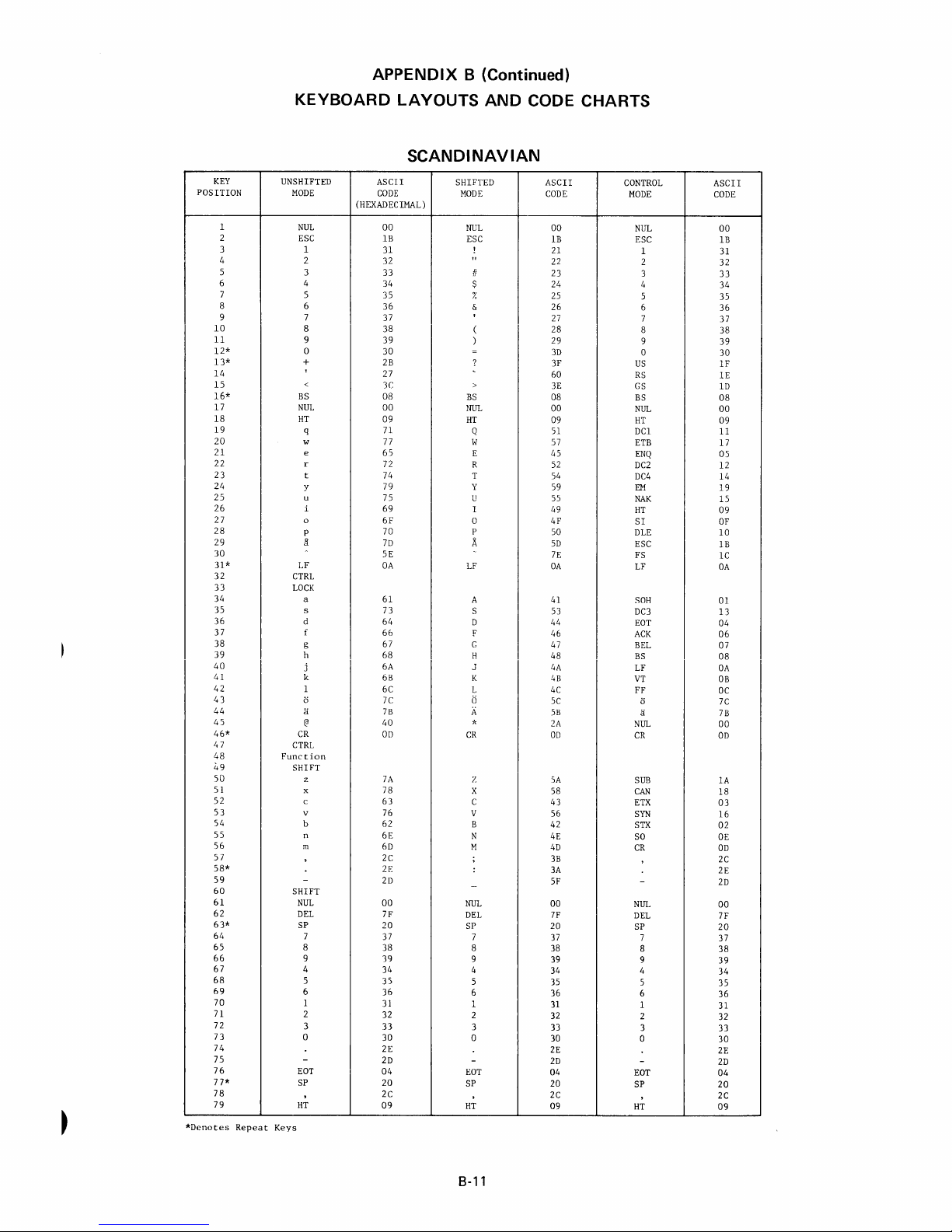
POSITION
*Denotes
KEY
10
11
12*
13*
14
15
16*
17
18
19
20
21
22
23
24
25
26
27
28
29
30
31*
32
33
34
35
36
37
38
39
40
41
42
43
44
45
46*
47
48
49
50
51
52
53
54
55
56
57
58*
59
60
61
62
63*
64
65
66
67
68
69
70
71
72
73
74
75
76
77*
78
79
1
2
3
4
5
6
7
8
9
Repeat
KEYBOARD
UNSHIFTED
MODE
NUL
ESC
1
2
3
4
5
6
7
8
9
0
+
<
BS
NUL
HT
q
w
e
r
t
y
u
i
0
P
il
LF
CTRL
LOCK
a
s
d
f
g
h
j
k
1
a
a
@
CR
CTRL
Function
SHIFT
z
x
c
v
b
n
m
-
SHIFT
NUL
DEL
SP
7
8
9
4
5
6
1
2
3
0
-
EOT
SP
HT
Keys
APPENDIX B (Continued)
LAYOUTS AND CODE CHARTS
SCANDINAVIAN
ASCII
CODE
(HEXADECIMAL)
00
IB
31
32
33
34
35
36
37
38
39
30
2B
27
3C
08
00
09
71
77
65
72
74
79
75
69
6F
70
7D
5E
OA
61
73
64
66
67
68
6A
6B
6C
7C 0
7B
40
OD
7A
78
63
76
62
6E
6D
2C
2E
2D
00
7F
20
37
38
39
34
35
36
31
32
33
30
2E
2D
04
20
2C
09
SHIFTED
MODE
NUL
ESC
!
"
II
$
%
&
(
)
=
?
>
BS
NUL
HT
Q
W
E
R 52
T
Y
U
I
0
P
A
LF
A
S
D
F
C
H
J
K
L 4C
A
*
CR
Z
X
C
V
B
N
M
;
:
-
NUL
DEL
SP
7
8
9
4
5
6
1
2
3
0
-
EOT
SP
HT
ASCII
CODE
00
IB
21
22
23
24
25
26
27
28
29
3D
3F
60
3E
08
00
09
51
57
45
54
59
55
49
4F
50
5D
7E
OA
41
53
44
46
47
48
4A
4B
5C
5B
2A
OD
SA
58
43
56
42
4E
4D
3B
3A
SF
00
7F
20
37
38
39
34
35
36
31
32
33
30
2E
2D
04
20
2C
09
CONTROL
MODE
NUL
ESC
1
2
3
4
5
6
7
8
9
0
US
RS
GS
BS
NUL
HT
DCl
ETB
ENQ
DC2
DC4
EM
NAK
HT
SI
DLE
ESC
FS
LF
SOH
DC3
EOT
ACK
BEL
BS
LF
VT
FF
ii
a
NUL
CR
SUB
CAN
ETX
SYN
STX
SO
CR
-
NUL
DEL
SP
7
8
9
4
5
6
1
2
3
0
-
EOT
SP
HT
ASCII
CODE
00
IB
31
32
33
34
35
36
37
38
39
30
IF
lE
ID
08
00
09
11
17
05
12
14
19
15
09
OF
10
IB
lC
OA
01
13
04
06
07
08
OA
OB
DC
7C
7B
00
OD
lA
18
03
16
02
OE
OD
2C
2E
2D
00
7F
20
37
38
39
34
35
36
31
32
33
30
2E
2D
04
20
2C
09
8-11
Page 74

KEYBOARD
APPENDIX B (Cont'd.)
LAYOUTS
AND
CODE CHARTS
NORSK
8
8
§
-
Position Numbers above key
code
chart
table. Control codes
referenced below key
These legends are
100%
compatible
tops
identify
not
engraved
printwheels:
tops
on
key
38148
refer
to
accompanying
and
special symbols
"CTR
L"
mode
tops.
Norsk Pica 10
output.
When UPPER CASE
positions
equivalents before being
29,
43,
ON
and
L Y
is
used, lower case characters
44
are
converted
printed
8-12
or
transmitted.
to
upper
in
case
Page 75

KEY
POSITION
10
11
12*
13*
14
15
16*
17
18
19
30
*Denotes
1
2
3
4
5
6
7
8
9
20
21
22
23
24
25
26
27
28
29
31*
32
33
34
35
36
37
38
39
40
41
42
43
44
45
46*
47
48
49
50
51
52
53
54
55
56
57
58*
59
60
6]
62
63*
64
65
66
67
68
69
70
71
72
73
74
75
76
77*
78
79
Repeat
APPENDIX B (Continued)
KEYBOARD LAYOUTS AND CODE CHARTS
NORSK
UNSHIFTED
MODE
NUL
ESC
1
2
3
4
5
6
7
8
9
0
-
A
@
BS
NUL
HT
q
w
e
r
t
y
u
i
0
p
Jl
:
LF
CTRL
LOCK
a
s
d
f
g
h
j
k
1
1E
tJ
;
CR
CTRL
Function
SHIFT
z
x
c
v
b
n
m
/
SHIFT
DEL
DEL
SP
7
8
9
4 34
5
6
1
2 32
3
0
-
EOT
SP
HT
Keys
ASCII
CODE
(HEXADECIMAL)
00
IB
31
32
33
34
35
36
37
38
39
30
2D
5E
40
08
00
09
71 Q
77
65
72
74
79
75
69
6F
70
7D
3A
OA
61
73
64
66
67
68
6A J
6B K
6C
7B
7C
3B
OD
7A Z
78
63
76
62
6E
6D
2C
2E >
2F
7F
7F
20
37
38
39
35
36
31
33
30
2E
2D
04
20
2C
09
SHIFTED
MODE
NUL
ESC
!
"
£
$
%
&
,
(
)
-
=
-
BS
NUL
HT
W
E
R
T
Y
V
I
0
P
.l\.
*
LF
A
S
D
F
G
H
L
IE
+
"
CR
X
C
V
B
N
M
<
?
DEL
DEL
SP
7
8
9
4
5
6
1 31
2
3
0
-
EDT
SP
HT
ASCII
CODE
00
IB
21
22
23
24
25
26
27
28
29
SF
3D
7E
60
08
00
09
51
57
45
52
54
59
55
49
4F
50
5D
2A
OA
41
53
44
46
47
48
4A
4B
4C
5B <E
5C
2B
OD
SA
58
43
56
42
4E
4D
3C
3E
3F
7F
7F
20
37 7
38
39
34
35
36
32
33
30
2E
2D
04
20
2C
09
CONTROL
MODE
NUL
ESC
1
2
3
4
5
6
7
8
9
0
US
RS
GS
BS
NUL
HT
DC1
ETB
ENQ
DC2
DC4
EM
NAK
HT
SI
DLE
ESC
FS
LF
SOH
DC3
EOT
ACK
BEL
BS
LF
VT
FF
tJ
NUL
CR
SUB
CAN
ETX
SYN
STX
SO
CR
/
DEL
DEL
SP
8
9
4
5
6
1
2
3
0
-
EDT
SP
HT
ASCII
CODE
00
IB
31
32
33
34
35
36
37
38
39
30
IF
IE
ID
08
00
09
11
17
05
12
14
19
15
09
OF
10
IB
lC
OA
01
13
04
06
07
08
OA
OB
OC
7B
7C
00
OD
lA
18
03
16
02
DE
OD
2C
2E
2F
7F
7F
20
37
38
39
34
35
36
31
32
33
30
2E
2D
04
20
2C
09
8-13
Page 76

Page 77

Page 78

XEROX
Diablo
24500
IridustrialBoulevard
Hayward
•.
California
A
Xerox
Company
Systems
94545
Incorporatec
Printed
in U.S.A.
 Loading...