

Page 1
FS-C8008N
FS-C8008DN
Color Laser Printer
FS-C8008N
FS-C8008N
Operation Guide
Page 2

Cautions
• To prevent the printer from tipping over, the optional CA-31B caster kit must be installed when the printer is installed
with more than one paper feeder or a duplex unit. For detailed information on the CA-31B caster kit, see page A-11.
• Do not block the cooling air in and out vents and the exhaust duct against walls or with other objects. If the flow of
cooling air is blocked, heat will be built up in the printer, and there will be a risk of fire.
Note
Moisture condensation inside the printer can cause blurred printing. When a heavily blured printing occurred, turn printer
power off while the power cable is plugged to power. Then, open the front cover, draw the paper transfer unit fully out, and
draw the primary transfer unit out. Allow approximately 2 hours before use.
Page 3
Please read the Operation Guide before using the printer. Keep it close to the printer for
easy reference.
The sections of this guide and parts of the printer marked with symbols are safety warnings meant to protect the user,
other individuals and surrounding objects, and ensure correct and saf e usage of the printer . The symbols and their
meanings are indica ted below .
WARNING: Indicates that serious injury or even death may result from insufficient attention to or incorrect
compliance with the related points.
CAUTION: Indicates that personal injury or mechanical damage may result from insufficient attention to or
incorrect compliance with the related points.
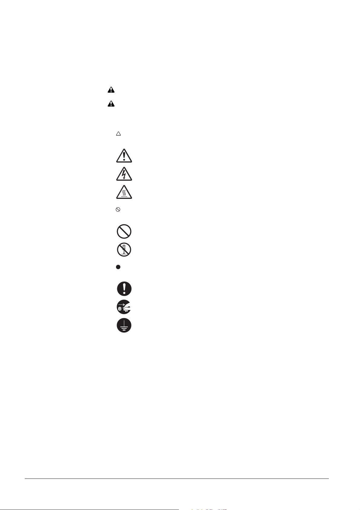
Symbols
The symbol indicates that the related section includes safety warnings. Specific points of attention are indicated
inside the symbol.
....................[General warning]
....................[Warning of danger of electrical shock]
....................[Warning of high temperature]
The symbol indicates that the related section includes information on prohibited actions. Specifics of the prohibited
action are indicated inside the symbol.
....................[Warning of prohibited action]
....................[Disassembly prohibited]
The symbol indicates that the related section includes information on actions which must be performed. Specifics
of the required action are indicated inside the symbol.
....................[Alert of required action]
....................[Remove the power plug from the outlet]
....................[Always connect the printer to an outlet with a ground connection]
Please contact your service representative to order a replacement if the safety warnings in the guide are illegible or if
the guide itself is missing. (fee required)
i
Page 4
Caution
NO LIABILITY IS ASSUMED FOR ANY DAMAGE CAUSED BY IMPROPER INSTALLA TION.
Notice on Software
SOFTW ARE USED WITH THIS PRINTER MUST SUPPORT THE PRINTER'S EMULA TION MODE. The printer
is factory-set to emulate the PCL. The emulation mode can be changed by following the pr ocedures described in
Chapter 3.
Notice
The information in this guide is subject to change without notification. Additional pages may be inserted in future
editions. The user is asked to excuse any technical inaccuracies or typographical errors in the present edition.
No responsibility is assumed if accidents occur while the user is following the instructions in this guide. No responsibility is assumed for defects in the printer's firmware (contents of its read-only memory).
This guide, any copyrightable subject matter sold or provided with or in connection with the sale of the page printer,
are protected by copyright. All rights are reserved. Copying or other reproduction of all or part of this guide, any
copyrightable subject matter without the prior written consent of Kyocera Mita Corporation is prohibited. Any copies
made of all or part of this guide, any copyrightable s ubject must contain the same copyright notice as the material from
which the copying is done.
Regarding Tradenames
PRESCRIBE is a registered trademark of Kyocera Corporation. KPDL is trademark of Kyocera Corporation.
Diablo 630 is a product of Xerox Corporation. IBM Proprinter X24E is a product of Inter national Business Machines
Corporation. Epson LQ-850 is a product of Seiko Epson Corporation.
Hewlett-Packard, PCL, and PJL are registered trademarks of Hewlett-Packard Company. Centronics is a trade name
of Centronics Data Computer Inc. PostScript is a registered trademark of Adobe Systems Incorporated. Macintosh is
a registered trademark of Apple Computer, Inc. Microsoft, Windows, and Windows NT are registered trademarks of
Microsoft Corporation. PowerPC and Microdrive are trademark s of International Business Machines Corporation .
CompactFlash is a trademark of SanDisk Corporation. ENERGY ST AR is a U.S. r egistered mark. All other brand and
product names are registered trademarks or trademarks of their respective companies.
This Kyocera Mita page printer uses PeerlessPrintXL to provide the HP LaserJet compatible PCL 6 language emulation. PeerlessPrintXL is a trademark of The Peerless Group, Redondo Beach , CA 90278, U.S.A.
This product was developed using the T ornado™ Real T ime Operating System and T ools from Wind River Systems.
This product contains UFST™ and MicroT ype® from Agfa Monotype Corp oration.
ii
Page 5

IBM PROGRAM LICENSE AGREEMENT
THE DEVICE YOU HA VE PURCHASED CONT AINS ONE OR MORE SOFTW ARE PROGRAMS ("PROGRAMS") WHICH BELONG TO INTERNA TIONAL BUSINESS MACHINES CORPORA TION ("IBM"). THIS
DOCUMENT DEFINES THE TERMS AND CONDITIONS UNDER WHICH THE SOFTW ARE IS BEING
LICENSED TO YOU BY IBM. IF YOU DO NOT AGREE WITH THE TERMS AND CONDITIONS OF THIS
LICENSE, THEN WITHIN 14 DAYS AFTER YOUR ACQUISITION OF THE DEVICE YOU MA Y RETURN THE
DEVICE FOR A FULL REFUND. IF YOU DO NOT SO RETURN THE DEVICE WITHIN THE 14 DA YS, THEN
YOU WILL BE ASSUMED TO HA VE AGREED TO THESE TERMS AND CONDITIONS.
The Programs are licensed not sold. IBM, or the applicable IBM country organization, grants you a license for the
Programs only in the country where you acqui red the Programs. Y ou obtain no rights other than those granted you un der
this license.
The term "Programs" means the original and all whole or partial copies of it, including modified copies or portions
merged into other programs. IBM retains title to the Programs. IBM owns, or has licensed from the owner, copyrights
in the Programs.
1. License
Under this license, you may use the Programs only with the device on which they are installed and transfer possession
of the Programs and the device to another party .
If you transfer the Programs, you must transfer a copy of this license and any other documentation to the other party.
Y our license is then terminated. The other party agrees to these terms and conditions by its first use of the Program.
Y ou may not:
1) use, copy, modify , merge, or transfer copies of the Program except as provided in this license;
2) reverse assemble or reverse compile the Program; or
3) sublicense, rent, lease, or assign the Program.
2. Limited Warranty
The Programs are provided "AS IS."
THERE ARE NO OTHER W ARRANTIES COVERING THE PROGRAMS (OR CONDITIONS), EXPRESS OR
IMPLIED, INCLUDING, BUT NOT LIMITED TO, THE IMPLIED WARRANTIES OF MERCHANT ABILITY
AND FITNESS FOR A PAR TICULAR PURPOSE.
Some jurisdictions do not allow the exclusion of implied warranties, so the above exclusion may not apply to you.
3. Limitation of Remedies
IBM's entire liability under this license is the following;
1) For any claim (including fundamental breach), in any form, related in any way to this license, IBM's liability will
be for actual damages only and will be limited to the greater of:
a) the equivalent of U.S. $25,000 in your local currency; or
b) IBM's then generally available license fee for the Program
This limitation will not apply to claims for bodily injury or damages to real or tangible personal property for which IBM
is legally liable.
IBM will not be liable for any lost profits, lost savings, or any incidental damages or other economic consequential
damages, even if IBM, or its authorized supplier, has been advised of the possibility of such damages. IBM will not be
liable for any damages claimed by you based on any third party claim. This limitation of remedies als o applies to any
developer of Programs supplied to IBM. IBM's and the developer's limitations of re medies are not cumulative. Such
developer is an intended beneficiary of this Section. Some jurisdictions do not allow these limitations or exclusions,
so they may not apply to you.
4. General
Y ou may terminate your license at any time. IBM may terminate your license if you fail to comply with the terms and
conditions of this license. In either event, you must destroy all your copies of the Program. Y ou are responsible for
payment of any taxes, including personal property taxes, resulting from this license. Neither party may bring an action,
regardless of form, more than two years after the cause of action arose. If you acquired the Program in the United States,
this license is governed by the laws of the State of New Y ork. If you acquired the Program in Canada, this license is
governed by the laws of the Province of Ontario. Otherwise, this license is governed by the laws of the co untry in which
you acquired the Program.
T ypeface Trademark Acknowledgement
All resident fonts in this printer are licensed from Agfa Corporation.
Helvetica, Palatino and Times are registered trademarks of Linotype-Hell AG. ITC Avant Garde Gothic, ITC
Bookman, ITC ZapfChancery and ITC Zapf Dingbats are registered tradem arks of International T ypeface Corpor ation.
iii
Page 6

Agfa Monotype License Agreement
1) "Software" shall mean the digitally encoded, machine readable, scalable outline data as encoded in a special
format as well as the UFST Software .
2) Y ou agree to accept a non-exclusive license to use the Software to reproduce and display weights, styles and
versions of letters, numerals, characters and symbols ("Typefaces") solely for your own customary business or
personal purposes at the address stated on the registration card you return to Agfa Japan. Under the terms of this
License Agreement, you have the right to use the Fonts on up to three printers. If you need to have access to the
fonts on more than three printers, you need to acquire a multi-user license agreement which can be obtained from
Agfa Japan. Agfa Japan retains all rights, title and interest to the Software and Typefaces and no rights are granted
to you other than a License to use the Software on the terms expressly set forth in this Agreement.
3) To protect prop rietary rights of Agfa Japan, you agree to maintain the Software and other proprietary information
concerning the Typefaces in strict confidence and to establish reasonable procedures regulating access to and use
of the Software and T ypefaces.
4) Y ou agree not to duplicate or copy the Software or T ypefaces, except that you may make one backup copy. You
agree that any such copy shall contain the same proprietary notices as those appearing on the original.
5) This License shall continue until the last use of the Software and Typefaces, unless sooner terminated. This License
may be terminated by Agfa Japan if you fail to comply with the terms of this License and such failure is not
remedied within thirty (30) days after notice from Agfa Japan. When this License expires or is terminated, you
shall either return to Agfa Japan or destroy all copies of the Software and Typefaces and documentation as
requested.
6) Y ou agree that you will not modify , alter, disassemble, decrypt, reverse engineer or decompile the Software.
7) Agfa Japan warrants that for ninety (90) days after delivery, the Software will perform in accordance with Agfa
Japan-published specifications, and the diskette will be free from defects in material and workm anship. Agfa
Japan does not warrant that the Software is free from all bugs, errors and omissions.
THE PAR TIES AGREE THAT ALL OTHER WARRANTIES, EXPRESSED OR IMPLIED, INCLUDING
W ARRANTIES OF FITNESS FOR A P AR TICULAR PURPOSE AND MERCHANT ABILITY, ARE
EXCLUDED.
8) Y our exclusive remedy and the sole liability of Agfa Japan in connection with the Software and Typefaces is repair
or replacement of defective parts, upon their return to Agfa Japan.
IN NO EVENT WILL AGFA JAP AN BE LIABLE FOR LOST PROFITS, LOST DA TA, OR ANY OTHER
INCIDENTAL OR CONSEQUENTIAL DAMAGES, OR ANY DAMAGES CAUSED BY ABUSE OR MISAPPLICA TION OF THE SOFTW ARE AND TYPEF ACES.
9) New Y ork, U.S.A. law governs this Agreement.
10) Y ou shall not sublicense, sell, lease, or otherwise transfer the Software and/or Typefaces without the prior written
consent of Agfa Japan.
11) Use, duplication or disclosure by the Government is subject to restrictions as set forth in the Rights in Technical
Data and Computer Software clause at F AR 252-227-701 3, subdivision (b)(3)(ii) or subparagraph (c) (1)(ii), as
appropriate. Further use, duplication or disclosure is subject to restrictions applicable to restricted rights software
as set forth in F AR 52.227-19 (c)(2).
12) YOU ACKNOWLEDGE THA T YOU HAVE READ THIS AGREEMENT, UNDERST AND IT , AND AGREE
TO BE BOUND BY ITS TERMS AND CONDITIONS. NEITHER PAR TY SHALL BE BOUND BY ANY
STATEMENT OR REPRESENTATION NOT CONTAINED IN THIS AGREEMENT . NO CHANGE IN THIS
AGREEMENT IS EFFECTIVE UNLESS WRITTEN AND SIGNED BY PROPERLY AUTHORIZED REPRESENTATIVES OF EACH PAR TY. BY OPENING THIS DISKETTE P ACKAGE, YOU AGREE TO ACCEPT
THE TERMS AND CONDITIONS OF THIS AGREEMENT.
iv
Page 7

FCC statement (for users in the United States)
This device complies with Part 15 of the FCC Rules. Operation is subject to the following two conditions: (1) This
device may not cause harmful interference, and (2) this device must accept any interference received, including interference that may cause undesired operation.
Note:
This equipment has been tested and found to comply with the limits for a Class B digital device, pursuant to Part 15 of
the FCC Rules. These limits are designed to provide reasonable protection against harmful interference in a residential
installation. This equipment generates, uses, and can radiate radio frequency energ y and, if not installed and used in
accordance with the instructions, may cause harmful interference to radio communications. However, there is not
guarantee that interference will not occur in a particular installation. If this equipment does not cause harmful interference to radio or television reception, which can be determined by turning the equipment off and on, the user is encouraged to try to correct the interference by one or more of the following measures:
• Reorient or relocate the receiving antenna.
• Increase the distance between the equipment and the receiver.
• Connect the equipment into an outlet on a circuit different from that used for the receiver.
• Consult the dealer or an experienced radio/TV technician for help.
Changes or modifications not expressly approved by the m anufacturer for compliance could void the user's authority
to operate the equipment. Shielded circular cables should be used for interfacing with the computer.
Cautions to the user:
• Any modifications without prior permission of Kyocera may cause harmful interference.
• If any modifications or changes are made to this equipment without prior permission of Kyocera, Kyocera as the
manufacturer does not guarantee the compliance with the FCC Rules.
• The use of equipment that does not comply with the FCC Rules is prohibited.
v
Page 8
Important Notes for Interface connectors
Be sure to power off the printer before connecting or disconnecting an interface cable. For protection against static
electricity discharge to the printer's internal electronics through the interface connector(s), cover any interface connector that is not in use with the protective cap supplied.
Use shielded interface cables.
Safety information
Laser safety:
This printer is certified as a Class 1 laser product under the U.S. Department of Health and Human Services (DHHS)
Radiation Performance Standard according to the Radiation Control for Health and Safety Act of 1968. This means
that the printer does not produce hazardous laser radiation. Because radiation emitted inside the printer is completely
confined within the protective housings and external covers, the laser beam cannot escape from the printer during any
phase of user operation.
Laser notice:
This printer is certified in the United States to conform to the requirements of DHHS 21 CFR Subchapter for Class I
(1) laser products, and is certified elsewhere as a Class I laser product conforming to th e requirements of IEC 825-1.
Cautions:
• Laser radiation will open. DO NOT STARE INTO THE BEAM OR VIEW THE BEAM DIRECTL Y WITH
OPTICAL INSTRUMENTS.
• Use of controls or adjustments or performance of procedures other than those specified herein may r esult in hazardous radiation exposure.
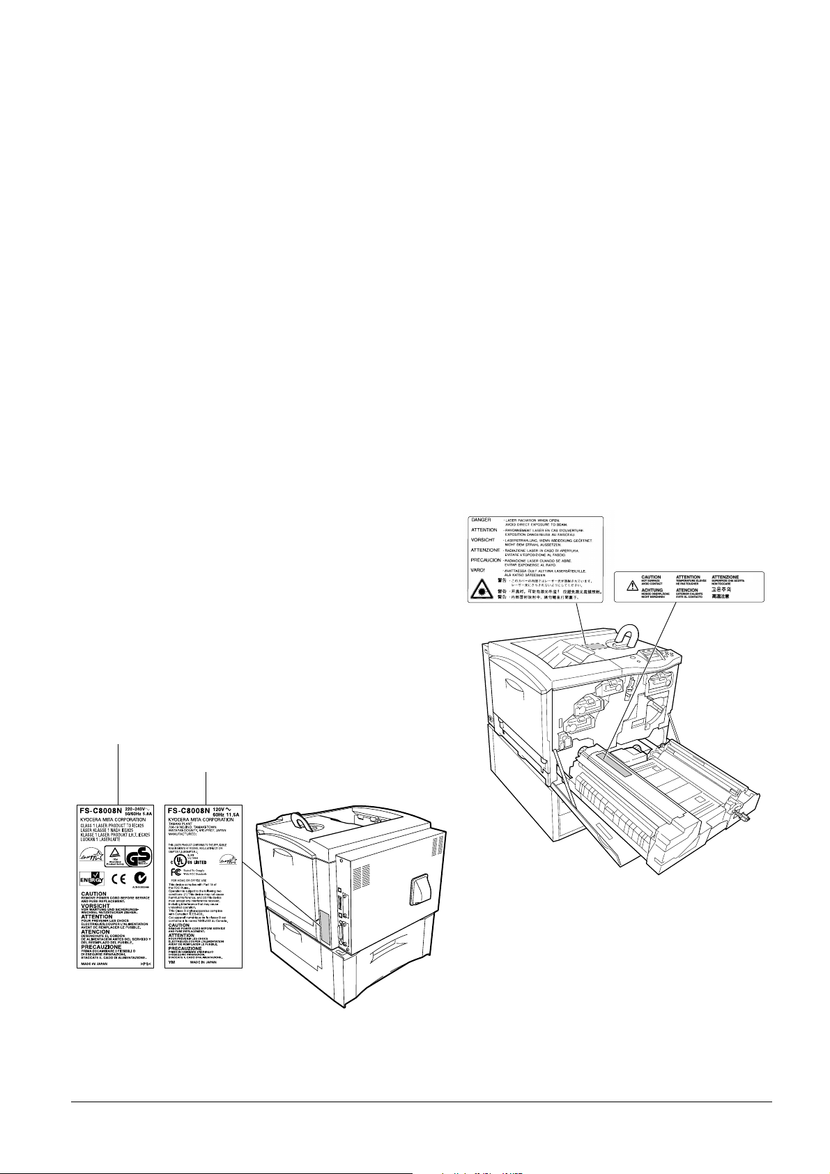
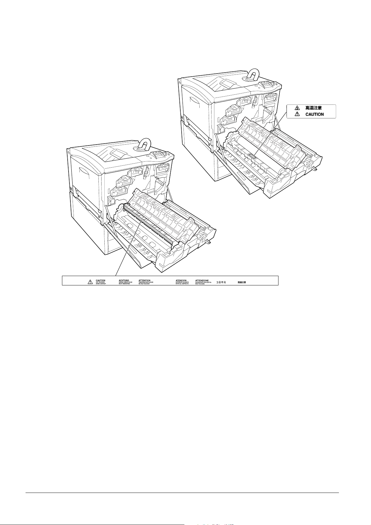
Cautionary Labels
For Europe, Asia,
and other countries
For U.S.A. and Canada
The printer bears any of the following labels.
Inside
vi
Page 9
U.S. CDRH regulations
The Center of Devices and Radiological Health (CDRH) of the U.S. Food and Drug Administration implemented
regulations for laser products on August 2, 1976. These regulations apply to las er products manufactured on and after
August 1, 1976. Compliance is mandatory for products marketed in the United States. A label indicating compliance
with the CDRH regulations must be attached to laser products marketed in the United States.
Ozone concentration
The printers generate ozone gas (O3) which may concentrate in the place of installation and cause an unpleasant smell.
To minimize the concentration of ozone gas to less than 0.1 ppm, we recommend you not to install the printer in a
confined area where ventilation is blocked.
vii
Page 10

Declaration of Conformity for U.S.A.
Model name: Color Laser Printer FS-C8008N
Trade name: Kyocera Mita
Responsible party: Kyocera Mita America, Inc.
Address: 225 Sand Road PO Box 40008 Fairfield, New Jersey 07004-0008, U. S.A.
Telephone: (9 73) 808-8444
Fax: (973) 882-6000
Contact person for technical matter: Ryozo Kojima
Phone: (973)-882-6019
Manufacturer: Kyocera Mita Corporation Tamaki Plant
Manufacturer’s address: 704-19, Nojin o, T amaki-cho, W atarai- gun, Mie-ken 519-0497, Japan
This device complies with Part 15 of the FCC Rules. Operation is subject to the following two conditions: (1) this
device may not cause harmful interference, and (2) this device must accept any interference received, including interference that may cause undesired operation.
The manufacturer and its merchandising companies retain the following technical documentation in anticipation of the
inspection that may be conducted by the authorities concerned.
User’s instruction that conforms to the applicable specifications.
Technical drawings.
Descriptions of the procedures that guarantee the conformity.
Other technical information.
Kyocera Mita America Inc.
CE Marking Directive
According to Council Directive 89/336/EEC and 73/23/EEC
Manufacturer: Kyocera Mita Corporation Tamaki Plant
Manufacturer’s address: 704-19, Nojin o, T amaki-cho, W atarai- gun, Mie-ken 519-0497, Japan
Declares that the product
Product name: Color Laser Printer
Model number: FS-C8008N
Conforms to the following product specifications:
The manufacturer and its merchandising companies retain the following technical documentation in anticipation of the
inspection that may be conducted by the authorities concerned.
User’s instruction that conforms to the applicable specifications.
Technical drawings.
Descriptions of procedures that guarantee conformity .
Other technical information.
(as tested with enhancement optional units; Duplex unit PD-800, Paper Feeder PF-30A, Document
Finisher DF-31 etc.)
EN 55 022: 1998 Class B
EN 61 000-3-2: 1995
EN 61 000-3-3: 1995
EN 55 024: 1998
EN 60 950: 1992+A1+A2+A3+A4+A11
EN 60 825-1: 1994+A11
viii
Page 11

Declaration of Conformity for Australia
Manufacturer: Kyocera Mita Corporation Tamaki Plant
Manufacturer’s address: 704-19, Nojino, Tamaki-cho, W atarai-gun, Mie-ken 519-0497, Japan
declares that the product
Product name: Color Laser Printer
Model name: FS-C8008N
Description of devices: This Page Printer Model FS-C8008N is the 31 ppm (monochrome)/8 ppm (color), A4 size and
utilized plane paper; laser; dry toner; etc. The printer can be equipped with several enhancement optional units as a
paper feeder as PF-30A, a duplex unit as PD-800, a mailbox/sorter as SO-30, IB-21E, etc.
conforms to the following product specifications:
AS/NZS 3548: 1995 (EN 55 022: 1998 Class B)
IEC60950 (EN 60 950: 1992+A1+A2+A3 +A4+A11)
IEC60825-1 (EN 60 825-1: 1994+A1 1)
The manufacturer and its merchandising companies retain the following technical documentation in anticipation of the
inspection that may be conducted by the authorities concerned.
User’s instruction that conforms to the applicable specifications
Technical drawings
Descriptions of procedures that guarantee conformity
Other technical information
The manufacturer has been employed with ISO9001 scheme. JQA and BS have attested the manufacturer.
Kyocera Mita Australia Pty., Ltd.
6-10 Talavera Road, North Ryde, NSW 2113, Australia
Telephone: +61 2-9888-9999
Fax: +61 2-9888-9588
Canadian Department of Communications compliance statement
This Class B digital apparatus complies with Canadian ICES-003.
Avis de conformité aux normes du ministere des Communications du Canada
Cet appareil numérique de la classe B est conforme a la norme NMB-003 du Canada.
ISO 7779
Maschinenlärminformationsverordnung 3. GSGV, 18.01.1991: Der höchste Sch alldruckpegel beträgt 70 dB (A) oder
weniger gemäß ISO 7779.
Disclaimer
Kyocera Mita will not be liable to customers or any other person or entity for any loss or damage caused or alleged to
be caused directly or indirectly by equipment sold or furnished by us, including but not limited to, any interruption of
service, loss of business or anticipatory profits, or consequential damages resu lting from the use or operation of the
equipment or software.
ix
Page 12
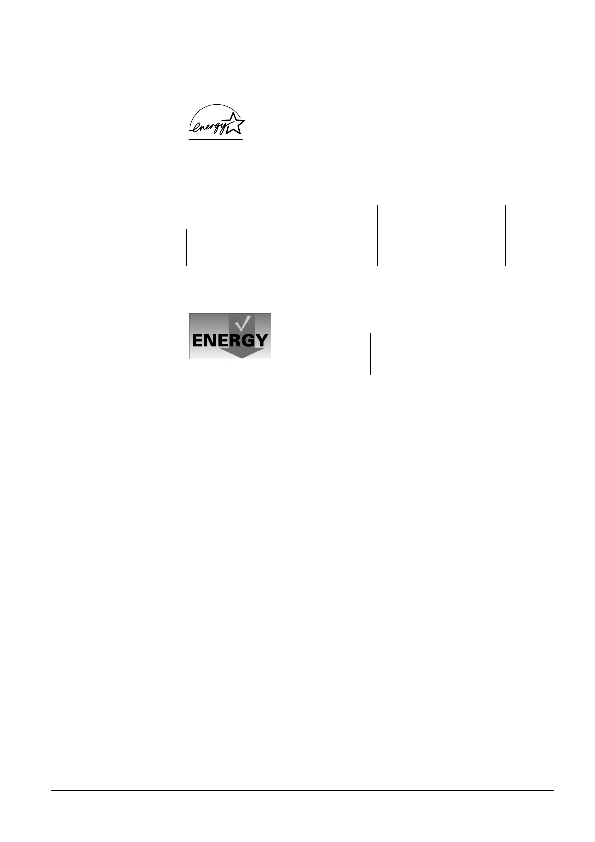
NERGY STAR
E
This printer is equipped with a sleep timer function that conforms with the standards of the E
This function makes it possible to reduce the amount of electrical power consumed by the printer. For maximum power
savings, turn off the printer’s power supply when not using the printer for extended periods of time.
For details on the sleep timer function and printer power consumption, refer to this manual.
Initial settings of the sleep timer function and power saved using the sleep timer function:
FS-C8008N 30 minutes (30 minutes) 22 W (35 W) [for U.S.A. and Canada]
( ): ENERGY STAR program guideline
®
As an ENERGY STAR Partner, we have determined that this product meets the ENERGY STAR
guidelines for energy efficiency.
The basic objective of the E
encouraging the manufacture and sale of equipment that uses energy more efficiently.
Initial sleep mode setting
NERGY STAR Program is to reduce environmental pollution by
NERGY STAR Program.
Power consumption in
sleep mode
26 W (35 W) [For Europe, Asia, and
other countries]
Group for Energy Efficient Appliances (GEEA)
The goal of GEEA is efficient use of energy . Th is product has a high-efficiency profile
and meets the criteria for receiving the GEEA-Label.
Initial sleep mode setting Power Consumption
Power off Sleep mode
30 min. (30 min.) 1 W (1 W) 26 W (30 W)
( ): GEEA criteria
x
Page 13
Installation Precautions
Environment
CAUTION
• A void placing the printer on or in locations which are unstable or not level. Such locations may
cause the printer to fall down or fall over. This type of situatio n presents a danger of personal
injury or damage to the printer . .......................................................................................
• A void locations with humidity or dust and dirt. If dust or dirt becomes attached to the power
plug, clean the plug to avoid the danger of fire or electrical shock. ......................................
• A void locations near radiators, heaters, or other heat sources, or locations near flammable
items, to avoid the danger of fire. ....................................................................................
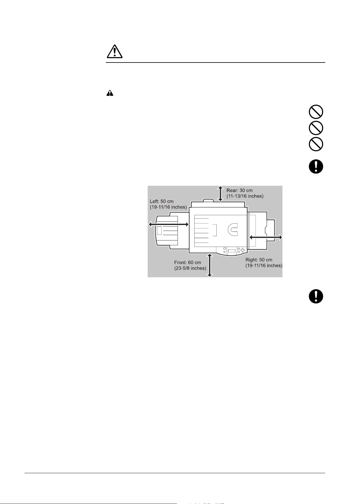
• To keep the printer cool and facilitate changing of parts and maintenance, allow access space
as shown below. Leave adequate space, especially around the side cover , to allow air to be
properly ventilated out of the printer. ...............................................................................
Left: 50 cm
(19-11/16 inches)
• Always use the caster stoppers to stabilize the printer once it is in place to keep it from moving
and/or falling over and causing injury. .............................................................................
Other Precautions
• Adverse environmental conditions may affect the safe operation and performance of the
printer. Install in an air-conditio ned room (recommended room temperature: around 20 °C,
humidity: around 65 % RH) and avoid the following locations when selecting a site for the
printer.
• A void locations near a window or with exposure to direct sunlight.
• A void locations with vibrations.
• A void locations with drastic temperature fluc tuations.
• A void locations with direct exposure to hot or cold air .
• A void poorly ventilated locations.
• If the floor is delicate against casters, when this product is moved after installation, the floor
material may be damaged.
xi
Page 14

Power Supply/Grounding the Printer
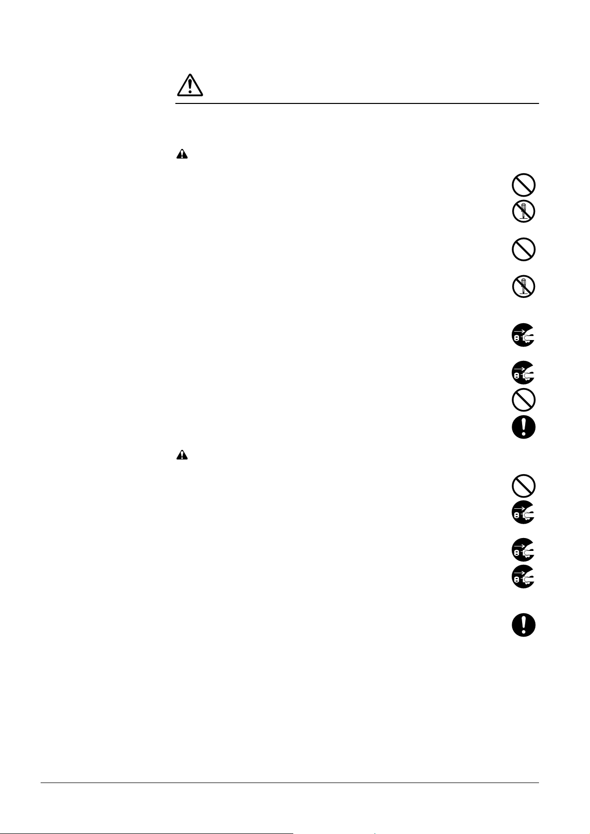
WARNING
• DO NOT use a power supply with a voltage other than that specified. Avoid multiple connec-
tions in the same outlet. These types of situations present a danger of fire or electrical shock...
• Plug the power cord securely into the outlet. If metallic objects come in contact with the prongs
on the plug, it may cause a fire or electric shock. ...............................................................
• Always connect the printer to an outlet with a ground connection to avoid the danger of fire or
electrical shock in case of an electric short. If an earth connection is not possible, contact your
service representative. ...................................................................................................
Other Precautions
• Connect the power plug to the closest outlet possible to the printer.
Handling of Plastic Bags
WARNING
• Keep the plastic bags that are used with the printer away from children. The plastic may cling
to their nose and mouth causing suffocation. ............................................................................
xii
Page 15
Precautions for Use
Cautions when Using the Printer
WARNING
• DO NOT place metallic objects or containers with water (flower vases, flower pots, cups, etc.)
on or near the printer. This type of situation presents a danger of fire or electrical shock should
they fall inside. .............................................................................................................
• DO NOT remove any of the covers from the printer as there is a danger of electrical shock from
high voltage parts inside the printer. ................................................................................
• DO NOT damage, break or attempt to repair the power cord. DO NOT place heavy objects on
the cord, pull it, bend it unnecessarily or cause any other type of damage.These types of situa-
tions present a danger of fire or electrical shock. ...............................................................
• NEVER attempt to repair or disassemble the printer or its parts as there is a danger of fire,
electrical shock or damage to the laser . If the laser beam escapes, there is a danger of it causing
blindness. ....................................................................................................................
• If the printer becomes excessively hot, smoke appears from the printer, there is an odd smell,
or any other abnormal situation occurs, there is a danger of fire or electrical shock. Turn the
power switch OFF ({) immediately , remove the power plug from the outlet and contact your
service representative. ...................................................................................................
• If anything harmful (paper clips, water, other fluids, etc.) falls into the printer , turn the power
switch OFF ({) immediately. Next, remove the power plug from the outlet to avoid the danger
of fire or electrical shock. Then contact your service representative. ...................................
• DO NOT remove or connect the power plug with wet hands, as there is a danger of electrical
shock. .........................................................................................................................
• ALWA YS contact your ser vice representative for maintenance or repair of internal parts. ......
CAUTION
• DO NOT pull the power cord when removing it from the outlet. If the power cord is pulled, the
wires may become broken and there is a danger of fire or electrical shock. (AL W A YS grasp the
power plug when removing the power cord from the outlet.) ..............................................
• ALWA YS remove the power plug from the outlet when moving the printer. If the power cord is
damaged, there is a danger of fire or electrical shock. ........................................................
• If the printer will not be used for a short period of time (overnight, etc.), turn the power switch
OFF ({). If it will not be used for an extended period of time (vacations, etc.), remove the power
plug from the outlet for safety purposes during the time the printer is not in use. ...................
• For safety purposes. ALWA YS remove the power plug from the outlet when performing clean-
ing operations. .............................................................................................................
• If dust accumulates within the printer, there is a danger of fire or other trouble. It is therefore
recommended that you consult with your service representative in regard to cleaning of internal
parts. This is particularly effective if accomplished prior to seasons of high humidity . Consult
with your service representative in regard to the cost of cleaning the internal parts of the printer.
xiii
Page 16

Other Precautions
• DO NOT place heavy objects on the printer or cause other damage to the printer.
• DO NOT open the front cover, turn off the main switch, or pull out the power plug during
printing.
• During printing, some ozone is released, but the amount does not cause any ill effect to one's
health. If, however, the printer is used over a long period of time in a poorly ventilated room or
when printing an extremely large number of copies, the smell may become unpleasant. T o
maintain the appropriate environment for print work, it is suggested that the room be properly
ventilated.
• DO NOT touch electrical parts, such as connectors or printed circuit boards. They could be
damaged by static electricity.
• DO NOT attempt to perform any operations not explained in this handbook.
• CAUTION: Use of controls or adjustments or performance of procedures other than those specified herein may result in hazardous radiation exposure.
• If the printer will not be used for an extended period of time, remove the paper from the cassette,
return it to its original package and reseal it.
Cautions for T oner Handling
CAUTION
• Do not incinerate toner and toner containers. Dangerous sparks may cause burn. ..................
• Never open the toner container........................................................................................
• Make sure not to inhale the toner, and not to rub your eyes or touch your mouth with the hand s
stained with the toner. And make sure not to stick to your skin. ................................................
• For the disposal of old toner container, consult your dealer . Or dispose of the toner or toner
containers in accordance with Federal, State and Local rules and regulations. ......................
• Keep away the toner container. .......................................................................................
xiv
Page 17

For More Information...
Item Description
Installation Guide
(paper manual)
Quick Reference Guide
(paper manual)
The following documents are stored in the CD-ROM as PDF documents.
Operation Guide (this manual) Guides you through topics concerning the operations and main-
KX Printer Drivers Operation Guide Describes how to install and set the printer driver.
PRESCRIBE Commands T echnical
Reference
PRESCRIBE Commands Command
Reference
Describes procedures from printer setup to printing a test page.
Describes common information about the printer such as loading paper, understanding messages, etc. This guide can be
retained in the plastic pocket at the printer .
tenance of the printer.
PRESCRIBE is the native language of the Kyocera Mita
printers. This Technical Reference contain s the information
about how the printing is performed using the PRESCRIBE
commands as well as the font and emulation description. Also
included is a list of permanent parameters and their explana tion
needed when customizing your printer.
Gives a detailed explanation of the PRESCRIBE command
syntax and parameters with the aid of print examples.
xv
Page 18

Guide to the Operation Guide
This Operation Guide has the following chapters:
Chapter 1 Introduction
This chapter explains printer features and the names of parts.
Chapter 2 Handling Paper
This chapter explains the types of paper that can be used with the printer.
Chapter 3 Using the Operator Panel
This chapter explains the message display, indicators and keys on the operator panel, and
how to make various settings from the operator panel.
Chapter 4 Troubleshooting
This chapter explains how to handle printer problems that may occur, such as paper jams.
Chapter 5 Maintenance
This chapter explains how to replace the toner container and how to care for your printer.
Appendix A Options
This appendix introduces the available options to be used with the printer.
Appendix B Computer Interface
This appendix explains the pin assignment and specifications for the printer’s parallel
interface, USB interface, and serial interface.
Appendix C Technical Specifications
This appendix lists the printer’s specifications.
xvi
Page 19

Contents
Contents
Chapter 1 Introduction
1.1 Features . . . . . . . . . . . . . . . . . . . . . . . . . . . . . . . . . . . . . . . . . . . . . . . 1-2
1.1.1 General . . . . . . . . . . . . . . . . . . . . . . . . . . . . . . . . . . . . . . . . . . . . . . . . 1-2
1.1.2 Hardware . . . . . . . . . . . . . . . . . . . . . . . . . . . . . . . . . . . . . . . . . . . . . .1-2
1.1.3 Software . . . . . . . . . . . . . . . . . . . . . . . . . . . . . . . . . . . . . . . . . . . . . . . 1-3
1.1.4 Networking . . . . . . . . . . . . . . . . . . . . . . . . . . . . . . . . . . . . . . . . . . . . . 1-4
1.2 Parts and Functions . . . . . . . . . . . . . . . . . . . . . . . . . . . . . . . . . . . . . 1-5
1.2.1 Front . . . . . . . . . . . . . . . . . . . . . . . . . . . . . . . . . . . . . . . . . . . . . . . . . .1-5
1.2.2 Internal . . . . . . . . . . . . . . . . . . . . . . . . . . . . . . . . . . . . . . . . . . . . . . . . 1-7
1.2.3 Rear . . . . . . . . . . . . . . . . . . . . . . . . . . . . . . . . . . . . . . . . . . . . . . . . . . 1-9
Chapter 2 Handling Paper
2.1 General . . . . . . . . . . . . . . . . . . . . . . . . . . . . . . . . . . . . . . . . . . . . . . . 2-2
2.1.1 Available paper types . . . . . . . . . . . . . . . . . . . . . . . . . . . . . . . . . . . . . 2-2
2.1.2 Paper specifications . . . . . . . . . . . . . . . . . . . . . . . . . . . . . . . . . . . . . . 2-2
2.1.3 Minimum and Maximum Paper Sizes . . . . . . . . . . . . . . . . . . . . . . . . . 2-3
2.1.4 Recommended Paper . . . . . . . . . . . . . . . . . . . . . . . . . . . . . . . . . . . . . 2-3
2.2 Selecting the Right Paper . . . . . . . . . . . . . . . . . . . . . . . . . . . . . . . . 2-4
2.2.1 Guidelines . . . . . . . . . . . . . . . . . . . . . . . . . . . . . . . . . . . . . . . . . . . . . . 2-4
2.2.2 Paper properties . . . . . . . . . . . . . . . . . . . . . . . . . . . . . . . . . . . . . . . . . 2-5
2.2.3 Other properties of paper . . . . . . . . . . . . . . . . . . . . . . . . . . . . . . . . . . 2-7
2.3 Loading Paper . . . . . . . . . . . . . . . . . . . . . . . . . . . . . . . . . . . . . . . . . . 2-8
2.3.1 Loading Paper into the Cassette . . . . . . . . . . . . . . . . . . . . . . . . . . . . 2-8
2.3.2 Loading Paper into the MP (Multi-Purpose) Tray . . . . . . . . . . . . . . . 2-10
2.4 Special Paper . . . . . . . . . . . . . . . . . . . . . . . . . . . . . . . . . . . . . . . . . 2-11
2.4.1 Selecting the Special Paper . . . . . . . . . . . . . . . . . . . . . . . . . . . . . . . 2-11
Chapter 3 Using the Operator Panel
3.1 Understanding the Operator Panel . . . . . . . . . . . . . . . . . . . . . . . . .3-2
3.1.1 Message Display . . . . . . . . . . . . . . . . . . . . . . . . . . . . . . . . . . . . . . . . 3-2
3.1.2 Indicators in Message Display . . . . . . . . . . . . . . . . . . . . . . . . . . . . . .3-3
3.1.3 Keys . . . . . . . . . . . . . . . . . . . . . . . . . . . . . . . . . . . . . . . . . . . . . . . . . . 3-6
3.2 Using the Menu Selection System . . . . . . . . . . . . . . . . . . . . . . . . .3-8
3.2.1 Menu Selection System . . . . . . . . . . . . . . . . . . . . . . . . . . . . . . . . . . .3-8
3.2.2 Menu System Road Map . . . . . . . . . . . . . . . . . . . . . . . . . . . . . . . . . 3-10
3.3 Menu Map and Status Pages . . . . . . . . . . . . . . . . . . . . . . . . . . . . . 3-15
3.3.1 Printing a Menu Map . . . . . . . . . . . . . . . . . . . . . . . . . . . . . . . . . . . . . 3-15
3.3.2 Printing a Status Page . . . . . . . . . . . . . . . . . . . . . . . . . . . . . . . . . . .3-17
3.4 e-MPS . . . . . . . . . . . . . . . . . . . . . . . . . . . . . . . . . . . . . . . . . . . . . . . . 3-20
3.4.1 Using Quick Copy . . . . . . . . . . . . . . . . . . . . . . . . . . . . . . . . . . . . . . . 3-21
3.4.2 Using Proof-and-Hold . . . . . . . . . . . . . . . . . . . . . . . . . . . . . . . . . . . . 3-23
3.4.3 Printing a Private Print/Job Retention . . . . . . . . . . . . . . . . . . . . . . . . 3-24
3.4.4 Retrieving Jobs from Virtual Mailbox (VMB) . . . . . . . . . . . . . . . . . . . 3-28
3.4.5 Changing e-MPS Configuration . . . . . . . . . . . . . . . . . . . . . . . . . . . . 3-30
3.5 Changing the Interface Parameters . . . . . . . . . . . . . . . . . . . . . . . 3-34
3.5.1 Changing Parallel Interface Mode . . . . . . . . . . . . . . . . . . . . . . . . . . . 3-34
3.5.2 Changing Serial Interface Parameters . . . . . . . . . . . . . . . . . . . . . . .3-35
3.5.3 Changing Network Interface Parameters . . . . . . . . . . . . . . . . . . . . .3-37
3.5.4 Resolving IP Address . . . . . . . . . . . . . . . . . . . . . . . . . . . . . . . . . . . . 3-39
3.6 Making Default Settings . . . . . . . . . . . . . . . . . . . . . . . . . . . . . . . . . 3-42
3.6.1 Default Emulation . . . . . . . . . . . . . . . . . . . . . . . . . . . . . . . . . . . . . . . 3-42
3.6.2 KC-GL Pen Width and Color . . . . . . . . . . . . . . . . . . . . . . . . . . . . . . . 3-43
xviii
Page 20

Contents
3.6.3 Alternative Emulation for KPDL Emulation . . . . . . . . . . . . . . . . . . . . 3-44
3.6.4 Printing KPDL Errors . . . . . . . . . . . . . . . . . . . . . . . . . . . . . . . . . . . . 3-45
3.6.5 Default Font . . . . . . . . . . . . . . . . . . . . . . . . . . . . . . . . . . . . . . . . . . . 3-46
3.7 Pagination . . . . . . . . . . . . . . . . . . . . . . . . . . . . . . . . . . . . . . . . . . . . 3-53
3.7.1 Number of Copies . . . . . . . . . . . . . . . . . . . . . . . . . . . . . . . . . . . . . . 3-53
3.7.2 Print Orientation . . . . . . . . . . . . . . . . . . . . . . . . . . . . . . . . . . . . . . . . 3-54
3.7.3 Page Protect Mode . . . . . . . . . . . . . . . . . . . . . . . . . . . . . . . . . . . . . . 3-55
3.7.4 Linefeed (LF) Action . . . . . . . . . . . . . . . . . . . . . . . . . . . . . . . . . . . . . 3-56
3.7.5 Carriage-Return (CR) Action . . . . . . . . . . . . . . . . . . . . . . . . . . . . . . 3-57
3.8 Setting Print Quality . . . . . . . . . . . . . . . . . . . . . . . . . . . . . . . . . . . . 3-58
3.8.1 Tone Mode . . . . . . . . . . . . . . . . . . . . . . . . . . . . . . . . . . . . . . . . . . . . 3-58
3.8.2 Gloss Mode . . . . . . . . . . . . . . . . . . . . . . . . . . . . . . . . . . . . . . . . . . . 3-59
3.9 Operating the Storage Device . . . . . . . . . . . . . . . . . . . . . . . . . . . . 3-60
3.9.1 Using the Memory Card . . . . . . . . . . . . . . . . . . . . . . . . . . . . . . . . . . 3-60
3.9.2 Using the Option Hard Disk . . . . . . . . . . . . . . . . . . . . . . . . . . . . . . . 3-67
3.9.3 Using the RAM Disk . . . . . . . . . . . . . . . . . . . . . . . . . . . . . . . . . . . . . 3-67
3.10 Paper Handling . . . . . . . . . . . . . . . . . . . . . . . . . . . . . . . . . . . . . . . . 3-69
3.10.1 MP Tray Mode . . . . . . . . . . . . . . . . . . . . . . . . . . . . . . . . . . . . . . . . . 3-69
3.10.2 Setting MP Tray Paper Size . . . . . . . . . . . . . . . . . . . . . . . . . . . . . . . 3-70
3.10.3 Setting the MP Tray Paper Type . . . . . . . . . . . . . . . . . . . . . . . . . . . 3-72
3.10.4 Setting the Cassette Paper Type . . . . . . . . . . . . . . . . . . . . . . . . . . . 3-73
3.10.5 Selecting the Paper Feed Source . . . . . . . . . . . . . . . . . . . . . . . . . . 3-74
3.10.6 Duplex Printing (FS-C8008DN) . . . . . . . . . . . . . . . . . . . . . . . . . . . . 3-75
3.10.7 Overriding Difference between A4 and Letter . . . . . . . . . . . . . . . . . 3-77
3.10.8 Creating Custom Paper Types . . . . . . . . . . . . . . . . . . . . . . . . . . . . . 3-78
3.10.9 Resetting the Custom Paper Type . . . . . . . . . . . . . . . . . . . . . . . . . . 3-80
3.10.10 Selecting the Output Stack . . . . . . . . . . . . . . . . . . . . . . . . . . . . . . . . 3-81
3.10.11 Selecting the Option Sorter Mode . . . . . . . . . . . . . . . . . . . . . . . . . . 3-82
3.11 Selecting Monochrome or Color Printing . . . . . . . . . . . . . . . . . . 3-85
3.12 Reading Life Counters . . . . . . . . . . . . . . . . . . . . . . . . . . . . . . . . . . 3-86
3.12.1 Displaying the Total Printed Pages . . . . . . . . . . . . . . . . . . . . . . . . . 3-86
3.12.2 Resetting the Toner Counter . . . . . . . . . . . . . . . . . . . . . . . . . . . . . . 3-87
3.13 Other Modes . . . . . . . . . . . . . . . . . . . . . . . . . . . . . . . . . . . . . . . . . . 3-88
3.13.1 Selecting the Message Language . . . . . . . . . . . . . . . . . . . . . . . . . . 3-88
3.13.2 Automatic Form Feed Timeout Setting . . . . . . . . . . . . . . . . . . . . . . . 3-89
3.13.3 Setting the Sleep Timer . . . . . . . . . . . . . . . . . . . . . . . . . . . . . . . . . . 3-90
3.13.4 Received Data Dump . . . . . . . . . . . . . . . . . . . . . . . . . . . . . . . . . . . . 3-92
3.13.5 Printer Resetting . . . . . . . . . . . . . . . . . . . . . . . . . . . . . . . . . . . . . . . . 3-93
3.13.6 Resource Protection . . . . . . . . . . . . . . . . . . . . . . . . . . . . . . . . . . . . . 3-94
3.13.7 Alarm (Buzzer) Setting . . . . . . . . . . . . . . . . . . . . . . . . . . . . . . . . . . . 3-95
3.13.8 Auto Continue Setting . . . . . . . . . . . . . . . . . . . . . . . . . . . . . . . . . . . 3-96
3.13.9 Setting the Auto Continue Recovery Time . . . . . . . . . . . . . . . . . . . . 3-97
3.13.10 Duplex Printing Error Detection Setting . . . . . . . . . . . . . . . . . . . . . . 3-98
3.13.11 Printing the Service Status Page . . . . . . . . . . . . . . . . . . . . . . . . . . . 3-99
3.13.12 Color Calibration . . . . . . . . . . . . . . . . . . . . . . . . . . . . . . . . . . . . . . . 3-100
Chapter 4 Troubleshooting
4.1 General Guidelines . . . . . . . . . . . . . . . . . . . . . . . . . . . . . . . . . . . . . . 4-2
4.1.1 Tips . . . . . . . . . . . . . . . . . . . . . . . . . . . . . . . . . . . . . . . . . . . . . . . . . . . 4-2
4.2 Print Quality Problems . . . . . . . . . . . . . . . . . . . . . . . . . . . . . . . . . . . 4-3
4.3 Error Messages . . . . . . . . . . . . . . . . . . . . . . . . . . . . . . . . . . . . . . . . 4-6
4.4 Clearing Paper Jams . . . . . . . . . . . . . . . . . . . . . . . . . . . . . . . . . . . 4-12
4.4.1 Possible Paper Jam Locations . . . . . . . . . . . . . . . . . . . . . . . . . . . . . 4-12
4.4.2 General considerations for clearing jams . . . . . . . . . . . . . . . . . . . . . 4-13
4.4.3 Paper Jam — Right Cover # . . . . . . . . . . . . . . . . . . . . . . . . . . . . . . 4-14
4.4.4 Paper Jam — Cassette # . . . . . . . . . . . . . . . . . . . . . . . . . . . . . . . . . 4-14
4.4.5 Paper Jam — MP Tray . . . . . . . . . . . . . . . . . . . . . . . . . . . . . . . . . . . 4-15
xix
Page 21

Contents
4.4.6 Paper Jam — Duplexer . . . . . . . . . . . . . . . . . . . . . . . . . . . . . . . . . . . 4-16
4.4.7 Paper Jam — Paper Transfer Unit . . . . . . . . . . . . . . . . . . . . . . . . . . 4-17
4.4.8 Paper Jam — Left Cover . . . . . . . . . . . . . . . . . . . . . . . . . . . . . . . . . 4-22
4.4.9 Paper Jam — Option Stacker/Finisher/Sorter . . . . . . . . . . . . . . . . . . 4-23
Chapter 5 Maintenance
5.1 Toner Container Replacement . . . . . . . . . . . . . . . . . . . . . . . . . . . . . 5-2
5.1.1 Frequency of toner container replacement . . . . . . . . . . . . . . . . . . . . . 5-2
5.1.2 Understanding Messages Requesting Toner Container Replacement 5-3
5.1.3 Replacing the Toner Container . . . . . . . . . . . . . . . . . . . . . . . . . . . . . .5-4
5.2 Replacing the Waste Toner Box . . . . . . . . . . . . . . . . . . . . . . . . . . . 5-6
5.3 Cleaning the Printer . . . . . . . . . . . . . . . . . . . . . . . . . . . . . . . . . . . . . 5-8
5.3.1 Cleaning the Paper Transfer Unit . . . . . . . . . . . . . . . . . . . . . . . . . . . .5-8
5.3.2 Cleaning the Main Charger Unit . . . . . . . . . . . . . . . . . . . . . . . . . . . . 5-12
Appendix A Options
A.1 Options . . . . . . . . . . . . . . . . . . . . . . . . . . . . . . . . . . . . . . . . . . . . . . .A-2
A.2 Expansion Memory Modules . . . . . . . . . . . . . . . . . . . . . . . . . . . . . .A-3
A.2.1 Installing the Memory Modules . . . . . . . . . . . . . . . . . . . . . . . . . . . . . .A-4
A.3 General Description of Options . . . . . . . . . . . . . . . . . . . . . . . . . . . .A-7
A.3.1 Memory Card . . . . . . . . . . . . . . . . . . . . . . . . . . . . . . . . . . . . . . . . . . .A-7
A.3.2 PF-30A Paper Feeder . . . . . . . . . . . . . . . . . . . . . . . . . . . . . . . . . . . . .A-8
A.3.3 PD-800 Duplex Unit . . . . . . . . . . . . . . . . . . . . . . . . . . . . . . . . . . . . . .A-9
A.3.4 SO-30 Sorter . . . . . . . . . . . . . . . . . . . . . . . . . . . . . . . . . . . . . . . . . . .A-10
A.3.5 ST-30 Bulk Stacker . . . . . . . . . . . . . . . . . . . . . . . . . . . . . . . . . . . . . .A-10
A.3.6 DF-31 Document Finisher . . . . . . . . . . . . . . . . . . . . . . . . . . . . . . . . .A-11
A.3.7 CA-31 Casters and CA-31B Caster Kit . . . . . . . . . . . . . . . . . . . . . . .A-11
A.3.8 Hard Disk . . . . . . . . . . . . . . . . . . . . . . . . . . . . . . . . . . . . . . . . . . . . .A-12
A.3.9 IB-20/IB-21E/IB-22 Network Interface Cards . . . . . . . . . . . . . . . . . .A-13
Appendix B Computer Interface
B.1 Parallel Interface . . . . . . . . . . . . . . . . . . . . . . . . . . . . . . . . . . . . . . . .B-2
B.1.1 Communication Modes . . . . . . . . . . . . . . . . . . . . . . . . . . . . . . . . . . . .B-2
B.1.2 Interface Signals . . . . . . . . . . . . . . . . . . . . . . . . . . . . . . . . . . . . . . . . .B-3
B.2 USB Interface . . . . . . . . . . . . . . . . . . . . . . . . . . . . . . . . . . . . . . . . . .B-5
B.2.1 Specifications . . . . . . . . . . . . . . . . . . . . . . . . . . . . . . . . . . . . . . . . . . .B-5
B.2.2 Interface Signals . . . . . . . . . . . . . . . . . . . . . . . . . . . . . . . . . . . . . . . . .B-5
B.3 Serial Interface (Option) . . . . . . . . . . . . . . . . . . . . . . . . . . . . . . . . . .B-6
B.3.1 Interface Signals . . . . . . . . . . . . . . . . . . . . . . . . . . . . . . . . . . . . . . . . .B-6
B.3.2 Interface voltage levels . . . . . . . . . . . . . . . . . . . . . . . . . . . . . . . . . . . .B-6
B.4 RS-232C Protocol . . . . . . . . . . . . . . . . . . . . . . . . . . . . . . . . . . . . . . .B-7
B.4.1 Parameters of the RS-232C Protocol . . . . . . . . . . . . . . . . . . . . . . . .B-7
B.4.2 PRESCRIBE FRPO D0 Command . . . . . . . . . . . . . . . . . . . . . . . . . . .B-8
B.5 RS-232C Cable Connection . . . . . . . . . . . . . . . . . . . . . . . . . . . . . . .B-9
B.5.1 Preparing an RS-232C Cable . . . . . . . . . . . . . . . . . . . . . . . . . . . . . . .B-9
B.5.2 Connecting the Printer to the Computer . . . . . . . . . . . . . . . . . . . . . . .B-9
Appendix C Technical Specifications
C.1 Printer Specification . . . . . . . . . . . . . . . . . . . . . . . . . . . . . . . . . . . . .C-2
C.2 Printing Speeds . . . . . . . . . . . . . . . . . . . . . . . . . . . . . . . . . . . . . . . .C-4
Index
xx
Page 22

Chapter 1 Introduction
W elcome to the professional color printer from Kyocera Mita. Using the Ecosys Color Printer,
you can now print top quality documents at 31 pages per minute for monochrome and 8 pages
per minute for color in A4, Letter, and A5 paper sizes.
The Kyocera Mita Ecosys Color FS-C8008N/DN Series printers are available in the following
two models:
Ecosys Color FS-C8008N
Basic model of the FS-C8008 Series. Equipped with two paper cassettes, each with a capacity
for holding 500 standard-size sheets of paper.
Ecosys Color FS-C8008DN
FS-C8008 Series model which is equipped with a duplexer (for two-sided printing) and a
paper cassette with a capacity for holding 500 standard-size sheets of paper.
Page 23

1.1 Features
1.1 Features
1.1.1 General
This section outlines the common major printer features of the FS-C8008N and the
FS-C8008DN Ecosys color laser printers.
Components with an ultra-long product life
The main printer components such as the imaging drum, development units, and fuser unit
have an ultra-long product life.
The imaging drum has been developed using Kyocera’s leading-edge ceramic technology
that makes full use of amorphous silicon.
USB (Universal Serial Bus) Interface
This printer supports Full-Speed USB 2.0. Connection to a computer with a USB interface
gives a higher communication speed than parallel interface connection.
High-speed printing
The printer supports print speeds of 31 pages per minute for monochrome outputs; and 8
pages per minute for color outputs. (Actual time varies according to page complexity.)
Superb color printing quality and versatile color control
This printer contains a mode that allows you to switch the gray level of each pixel between
2 bpp and 4 bpp (bits per pixel). The intelligent color calibration system automatically
optimizes colors every time the printer is powered.
Variety of paper sizes and types
In addition to ordinary paper, you can use print media such as transparencies, labels, and
other special papers for printouts.
Sleep mode
Conserves energy while printing is in standby.
1.1.2 Hardware
Advanced Performance Data Processing
A 400 MHz CPU, 128 MB of RAM, and the optional hard disk deliver ideal throughput for
wide varying printing applications.
1-2
Page 24

1.1 Features
Two expansion slots for hardware interfaces
The printer is equipped with two expansion slots for plugging in an optional network
interface card and a hard disk.
Standard bidirectional parallel interface
Ensures high-speed data transfer between the host computer and printer.
Memory card slot
You can select and read the data in a memory card set in this slot from the printer operator
panel.
Large-capacity paper cassettes
Each paper cassette can hold approximately 500 sheets of 80 g/m² paper which is 0.1 mm
thick. The printer also has a multipurpose tray that can hold approximately 150 sheets of
nonstandard size paper. Printed sheets can be stacked in the face-down output tray or an
optional face-up output tray.
1.1.3 Software
Displaying printer messages in any of eight languages
Printer messages can be displayed in English, French, German, Italian, Dutch, Danish,
Spanish, or Swedish.
e-MPS
‘e-MPS’ is an abbreviation for ‘enhanced-Multiple Printing System,’ which is a
post-processing function that combines electronic sorting, job retention, and virtual
mailboxing.
When printing multiple copies of a document, the data is transferred from the computer to
the printer only for the first copy; the data is then stored on the printer’s hard disk. Copies of
the document are printed using the stored data.
Printing is performed faster with less computer spooling time and less network traffic.
Furthermore, printed data that is stored on the hard disk can be called up using job retention
functions, such as Quick Copy etc., allowing you to quickly print additional copies of a
document from the printer at any time, without needing to re-spool the document or start up
the computer system.
Printer control language PRESCRIBE
The printer uses PRESCRIBE, Kyocera Mita’s page printer control language with enhanced
color graphics capabilities. The simple commands of PRESCRIBE allow the programmers
to easily define pagination and device control.
1-3
Page 25

1.1 Features
1.1.4 Networking
KPDL3 (Kyocera Printer Description Language 3)
The printer uses KPDL3, Kyocera’s implementation of the PostScript page description
language Level 3. The printer has 136 fonts that are compatible with Adobe PostScript
fonts. (The printer also has 80 PCL fonts.)
PDF417 two-dimensional bar codes
The printer has the built-in two-dimensional stacked bar codes of PDF 417 (Portable Data
File 417).
Account Management System
This printer comes equipped with an Account Management System function which records
the number of pages printed by each department. The administrator can preset the maximum
number of pages that each department will be allowed to print.
Built-in and external network interfaces
Because the network interface supports TCP/IP, IPX/SPX, NetBEUI and EtherTalk
protocols, network printing is possible with various environments including Windows,
Macintosh, UNIX and NetWare, etc.
Support for network printer monitor utility (KM-NET VIEWER)
Allows network wide management of printers. See the readme file in the CD-ROM
(supplied with the printer) for details.
1-4
Page 26
1.2 Parts and Functions
This section provides explanations and illustrations for you to determine the parts and their
functions. Try to be familiar with the names and functions of these parts for correct use and
optimal performance.
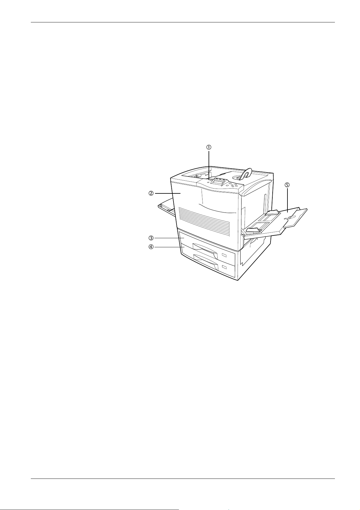
1.2.1 Front
1.2 Parts and Functions
Figure 1-1
1 Operator Panel
Used to specify printer functions and display the printer operating status.
2 Front Cover
When open, this cover gives you access to the internal component for replacing toner
containers. The cover must also be open to clear paper jam.
3 Top Paper Cassette (FS-C8008N)/Duplex Drawer (FS-C8008DN)
The cassette holds up to 500 sheets of A5 to A3 sizes. For the FS-C8008DN, the top
drawer includes the duplexer for two-sided printing.
4 Bottom Paper Cassette
The cassette holds up to 500 sheets of A5 to A3 sizes as a second paper source (for the
FS-C8008N).
5 MP (Multi-Purpose) Tray
The MP tray holds up to 150 sheets of standard and non-standard sizes with the
following weight:
• 150 sheets for 64 to 90 g/m²
• 30 sheets for 160 g/m² or more
Transparencies, envelopes, etc. must be fed using this tray.
1-5
Page 27
1.2 Parts and Functions
Caution
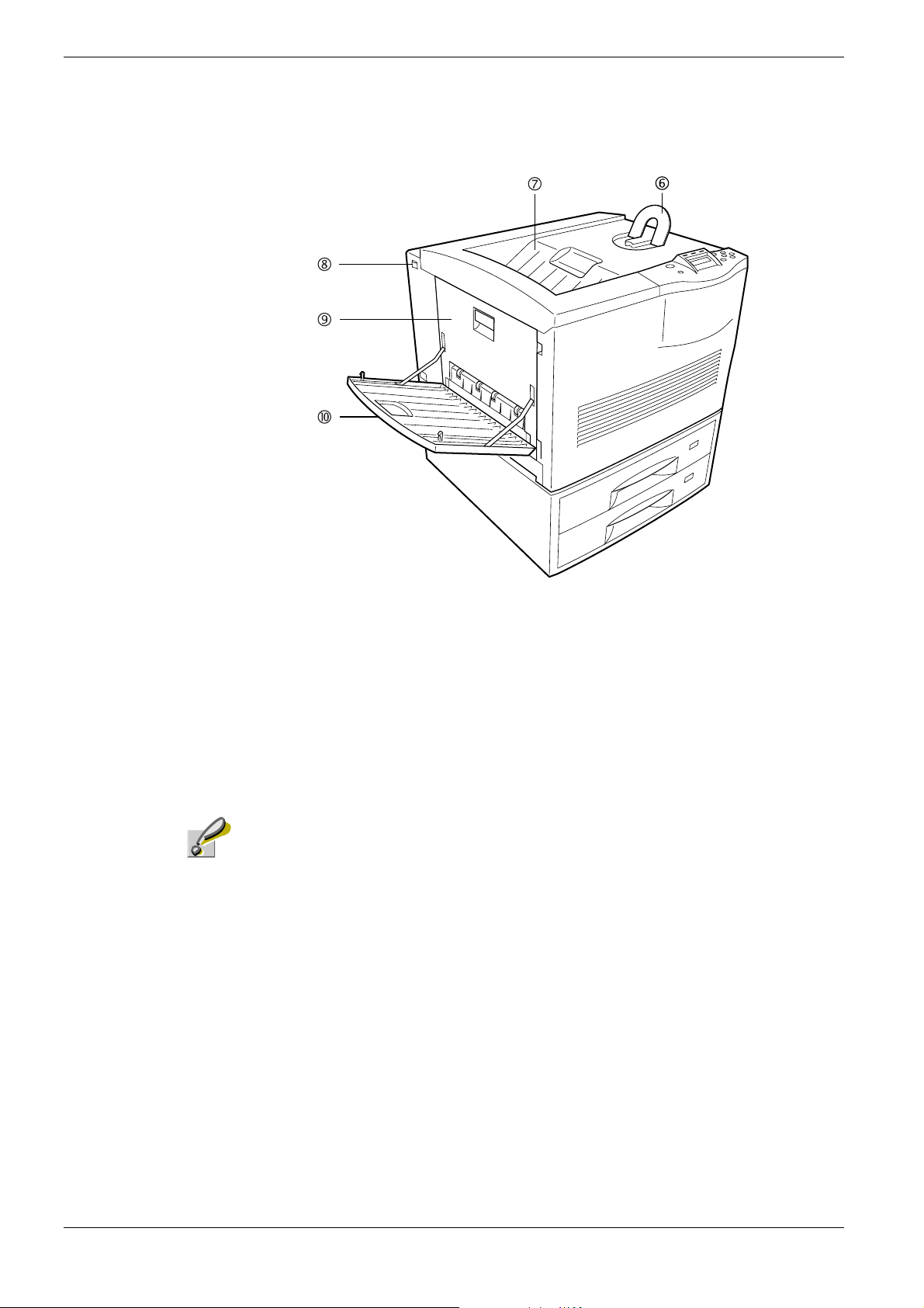
Figure 1-2
6 Paper Stopper
This stopper, when flipped up, prevents the printed sheet of large size from falling.
7 Face-down Tray
This tray receives printouts face down.
8 Power Switch
This switch turns printer power on and off.
In order to maintain operability and print quality , this printer operates a cooling fan for 30
minutes even after the power is turned off. For this reason, you should not unplug the
power cord even after turning off the power.
9 Left Cover
This cover is open by pulling the handle to clear paper jams.
10 Face-up Tray
This tray receives printouts face up.
1-6
Page 28
1.2.2 Internal
1.2 Parts and Functions
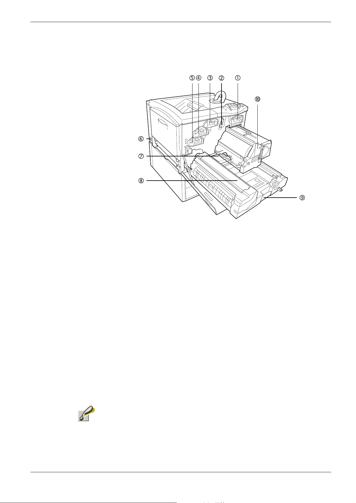
Figure 1-3
1 Black Toner Container
This container holds black (K) toner. You must replace the container when the toner
run out.
2 Main Charger Unit
This is an electrical component used to transfer the toner onto the drum unit. The main
charger unit must be cleaned when you replace the toner container.
3 Yellow Toner Container
This container holds yellow (Y) toner. You must replace the container when the toner
run out.
4 Magenta Toner Container
This container holds magenta (M) toner. You must replace the container when the toner
run out.
5 Cyan Toner Container
This container holds cyan (C) toner. You must replace the container when the toner run
out.
6 Power Cord Connector
This connector accepts the power cord supplied with the printer.
Caution
In order to maintain operability and print quality, this printer operates a cooling fan for 30
minutes even after the power is turned off. For this reason, you should not unplug the
power cord even after turning off the power.
1-7
Page 29

1.2 Parts and Functions
7Waste Toner Box
This plastic box collects waste toner for later disposal. The box has a cap which is used
to seal the box opening when being disposed of.
8Fuser Unit
The fuser unit fixes the toner permanently on the paper. The fuser becomes very hot
during printing.
9 Paper Transfer Unit
The paper transfer unit transports paper from the paper source for developing and
fixing images.
10 Primary Transfer Unit
This unit is used to create the image developed by toner and to transfer it onto the
surface of the paper.
1-8
Page 30
1.2.3 Rear
1.2 Parts and Functions
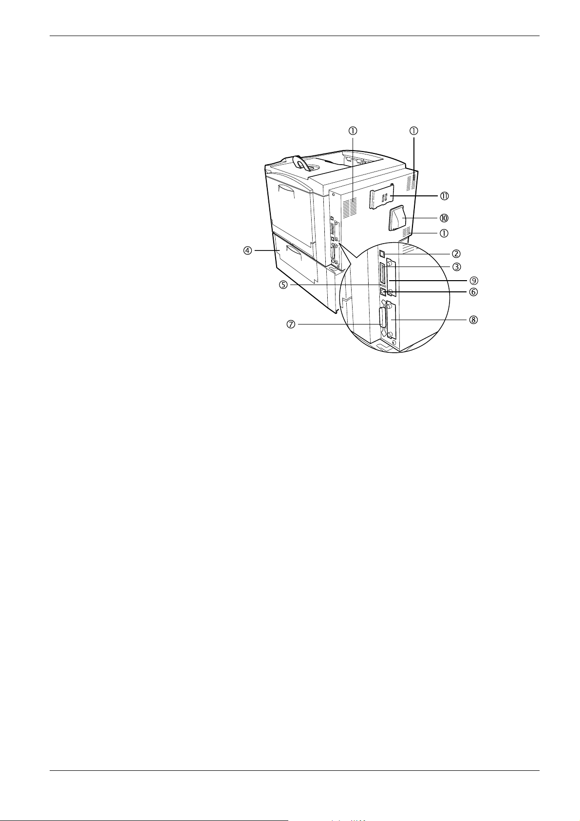
Figure 1-4
1Vents
Air is purged through these vents to cool down the inside.
2 USB Interface Connector
This connector is a USB interface that conforms to the Full-Speed USB 2.0. Use a USB
cable between this connector and the USB port on a computer.
3Memory Card Slot
This slot receives a memory card. A memory card can hold fonts, macros, forms, etc.,
that can be downloaded in the printer’s memory. For details, see Appendix A Options,
section A.3.1 Memory Card on page A-7.
4 Paper Feeder Right Cover
This cover is opened to clear paper jams in the paper feeder section.
5 Network indicators
These indicators light according to the communication status with the network.
10BASE-T indicator (10): Lights when you are connected to the network at 10 Mbps.
100BASE-TX indicator (100): Lights when you are connected to network at 100 Mbps.
Status indicator (ST): Flashes during data communication.
6 Network Interface Connector
Connects to the network via a 10BASE-T/100BASE-TX network cable.
7 Parallel Interface Connector
This connector is for a standard Centronics parallel interface cable from the computer.
Connect this connector to the computer’s parallel port.
8 Option Interface Card Slot (Network/Serial) [OPT]
This slot holds an optional network interface card for network printing or a serial
interface board kit. (An optional Hard disk can’t be used in this slot.) For details see
Appendix A Options.
1-9
Page 31

1.2 Parts and Functions
9 Hard Disk Slot (HDD)
This slot holds an optional hard disk for storing print jobs. A Kyocera Mita manufactured
hard disk must be used. For details, see Appendix A Options, section A.3.8 Hard Disk on
page A-12.
10 Exhaust Duct
Air is purged through these vents to cool down the inside.
11 Quick Reference Guide Holder
Use this holder to store the included Quick Reference Guide for easy access.
1-10
Page 32

Chapter 2 Handling Paper
The printer can use a variety of media in various sizes. However, any media you will choose
to use with the printer must be in accordance with the guidelines and specifications in this
chapter. Use of paper not satisfying these guidelines and s pecifications may cause problems
such as frequent paper jams, poor quality printing, and possible damage to the printer
mechanism.
Even meeting the instructions provided in this chapter, special media such as transparencies,
labels, envelopes, non-standard-size paper must be fed directly from the printer’s MP
(multi-purpose) tray and delivered in the face-up tray in ‘straight path’ manner. For details
on use of MP tray, see Chapter 3 Using the Operator Panel, section 3.10.1 MP Tray Mode
on page 3-69.
Page 33

2.1 General
2.1 General
The Ecosys Color FS-C8008 Series printers are designed for high-grade bond (copy) paper,
like those widely used for ordinary xerographic copiers. The printers will also support other
types of paper as long as they meet the standards explained in this chapter.
Selecting the right paper is very important. Use of unsuitable paper can cause paper jams,
misfeed, curling, poor print quality, and even worse, printer damage. This chapter shows
you how to use your printer in a way that will ensure efficient, error-free printing and
minimal printer damage. This practice will increase your office productivity.
Kyocera Mita will not be liable for any problems that may occur if you use paper that
does not meet these standards.
Note
2.1.1 Available paper types
The FS-C8008 Series printers can use almost any type of printer paper. These printers
accept paper used for xerographic copiers as well.
Paper comes in three generic grades: economy, standard, and premium. The grades are
determined by how easily the paper can pass through the printer. This depends on the
smoothness, size, moisture content, and cutting of the paper. The higher the grade, the less
risk of problems (such as paper jams), and higher the print quality.
The differences in paper characteristics of different paper makers also affect the printer
performance. High-performance printers can produce high-quality results only when the
right types of paper are selected. Low-priced paper is not always economical, especially if it
ends up causing frequent printing problems.
Paper of the different grades is available in basis weights (explained later). The recommended
basis weights of paper for the printers are 16, 20, and 24 pounds. When expressed in grams
per square meter, the recommended basis weights range from 60 to 90 g/m².
2.1.2 Paper specifications
Table 2-1 summarizes the basic paper specifications. Details are given on the subsequent
pages.
Item Values
W eight (basis weight) Cassette: 64 to 90 g/m² (17 to 24 lb/ream)
Thickness 0.086 to 0.110 mm (3.4 to 4.3 mils)
Dimensions See Table 2-3.
Dimensional accuracy
Squareness of corners
Moisture content 4 to 6 %
MP tray: 64 to 220 g/m² (17 to 58 lb/ream)
±
0.7 mm (±0.0276 inches)
±
0.2 °
90
†
T able 2-1
2-2
Page 34

Item Values
Direction of grain Long grain
Pulp content 80 % or more
Table 2-1 (Continued)
† Paper of 135 to 220 g/m² thick should be A4 or Letter size and fed laterally.
2.1.3 Minimum and Maximum Paper Sizes
The minimum and maximum paper sizes are as follows. For non standard paper such as
cut-sheet, the MP (multi-purpose) tray must be used.
148 mm
5-13/16 inches
2.1 General
Minimum
Paper
Size
Figure 2-1
2.1.4 Recommended Paper
The following products are recommended for use with the printer for optimum performance.
Size Product Weight
Letter, Legal Hammermill LASER PRINT 90 g/m² (24 lb)
A4, A3 NEUSIEDLER COLOR COPY 90 g/m²
458 mm
18 inches
80 mm
3-1/8 inches
Maximum
Paper Size
310 mm
12-3/16 inches
T able 2-2
2-3
Page 35

2.2 Selecting the Right Paper
2.2 Selecting the Right Paper
T o get clean, crisp printouts from laser printers all the time, select high-quality printer paper
that meets the printer’s requirements. Laser printers use laser beams, electrostatic discharge,
toner, and heat, all of which affect the paper. Furthermore, paper slide, bends, and twists as
it passes through laser printers during printing. Therefore, printer paper must be able to
withstand such great stress.
This section describes the major considerations for selecting the right printing paper.
2.2.1 Guidelines
Paper conditions
Do not use paper with folded edges, curls, warps, smudges, tears, or embossing. Also do
not use paper containing lint, clay, or paper debris. Using such paper may cause illegible
printing, misfeeds, paper jams, etc., and shorten the product life of the printer. Never use
paper with surface coating or other surface treatment. The paper surface should be as
smooth and even as possible.
Paper composition
Do not use paper with surface-coating or containing plastic or carbon. The heat of fusing
causes such paper to emit toxic fumes.
Bond paper should have at least an 80 % pulp content. The percentage of cotton and other
fibers should not exceed 20 %.
Paper sizes
Ta bl e 2- 3 lists the standard paper sizes and dimensions. Note that certain paper sizes are
available only for MP tray feeding (as remarked) and face-up tray delivering. For details on
using MP tray, seeChapter 3 Using the Operator Panel, section 3.10.1 MP Tray Mode on
page 3-69.
The dimensional tolerances for these paper sizes are
length and width of paper. The corner angles must be 90
MP tray S ize Cassette or MP tray Size
Monarch 3-7/8 × 7-1/2 inches Ledger 11 × 17 inches
Business 4-1/8 × 9-1/2 inches Legal 8-1/2 × 14 inches
Commercial #9 3-7/8 × 8-7/8 inches Letter 8-1/2 × 11 inches
Commercial #6-3/4 3-5/8 × 6-1/2 inches Executive 7-1/4× 10-1/2 inches
ISO DL 1 10 × 220 mm Folio 210 × 330 mm
ISO C5 162 × 229 mm ISO A3 297 × 420 mm
ISO A6 105 × 148 mm ISO A4 210 × 297 mm
JIS B6 128 × 182 mm ISO A5 148 × 210 mm
ISO B5 176 × 250 mm JIS B5 182 × 257 mm
A3 Wide 310 × 432 mm JIS B4 257 × 364 mm
±
0.7 mm (±0.0276 inches) for both
±
0.2 °.
T able 2-3
2-4
Page 36

2.2.2 Paper properties
2.2 Selecting the Right Paper
MP tray Size Cassette or MP tray Size
Ledger Wide 310 × 440 mm ISO C4 229 × 324 mm
Statement 5-1/2 × 8-1/2 inches Oficio II 8-1/2 × 13 inches
Hagaki 100 × 148 mm 8K 273 × 394 mm
Oufuku Hagaki 148 × 200 mm 16K 197 × 273 mm
Y oukei 2 114 × 162 mm
Y oukei 4 105 × 235 mm
Custom 80 × 148 mm to
310 × 458 mm
Table 2-3 (Continued)
Smoothness
Paper should have a smooth, uncoated surface. Paper with a rough or sandy surface can
cause gaps in printouts. However, paper with surfaces that are too smooth may cause
multiple-sheet feeding and fogging problems (fogging is a gray background effect).
Basis weights
Basis weight is the weight in pounds of 500 sheets (called a ream) of paper cut to the basic
size, which is 17
22 inches. The number of sheets in a ream and the basic paper size
×
relating to basis weights depend on paper classifications. In the metric system, the basis
weight is expressed in grams per square meter (g/m²).
Paper that is too heavy or too light may cause misfeeds, jams, and premature wear of printer
parts. Uneven weight of paper can cause multiple-sheet feeding, print defects, poor toner
fusing, blurring, and other print quality problems. The recommended basis weights for this
printer are between 64 and 90 g/m² (17 to 24 lb per ream).
When you use paper with basis weights of 135 to 220 g/m², use the face-up tray for
high-quality printouts.
Paper Weight Equivalence Table
The paper weight is listed with expression in U.S. bond weight (lb) and European metric
(g/m²). The shaded point indicates the standard weight.
U. S. Bond Weight (lb) Europe Metric Weight (g/m²)
16 60
17 64
20 75
21
22 81
24 90
27
80
100
T able 2-4
2-5
Page 37

2.2 Selecting the Right Paper
U. S. Bond Weight (lb) Europe Metric Weight (g/m²)
28 105
32 120
34 128
36 135
39 148
42 157
43 163
47 176
53 199
T able 2-4 (Continued)
Thickness (Caliper)
Thick paper is called high-caliper paper and thin paper is called low-caliper paper. Paper
used by the printer should be neither too thick nor too thin. If you encounter paper jam,
multiple-sheet feed, or too light printing problems, the paper may be too thin. If you
encounter paper jam or too heavy printing problems, the paper may be too thick. The
recommended thickness of a sheet for this printer is between 0.086 and 0.110 mm (from 3.4
to 4.3 mils).
Moisture content
Moisture content is the percentage of the weight of water in paper. Moisture affects the
appearance, feeding, curling, electrostatic properties, toner fusing of the paper.
The moisture content of paper varies with the relative humidity in the room. If the room is
too humid, paper will absorb more moisture. The edges will swell and the paper will
become wavy. If the room is too dry and the paper loses moisture, the edges shrink and
tighten, and the print contrast may be degraded.
Wavy or tight edges can cause paper misfeeds and misalignments. The recommended
moisture content is between 4 and 6 %.
T o maintain the correct moisture content level, store the paper in an environment that allows
moisture control. These are tips for moisture control:
• Store paper in a cool, dry place.
• Leave packages of paper wrapped as long as possible. Rewrap unused paper.
• Return paper to its paper carton, whenever possible. Place the cartons on a pallet or
other furniture so that they are not in direct contact with the floor.
• Before using paper stored for an extended period of time, condition it in the printer’s
environment for at least 48 hours.
• Do not expose paper to heat, direct sunlight, or damp.
Grain
Technically, grain is the direction of paper in the paper machine. Grain is parallel with the
direction of movement in the paper machine. Grain long means that the grain runs along the
length of the sheet, and grain short means that the grain runs along the width of the sheet.
Because grain short causes paper feed problems, always select grain long for the printers.
2-6
Page 38

2.2.3 Other properties of paper
Porosity
The density of paper structure, which indicates the compactness of the fiber bonding. It is
also the characteristic that allows air to pass through paper (i.e., air permeability).
Stiffness
The ability of paper to resist deformation under stress. In the printer, limp paper can buckle
and too stiff paper can bind. Both conditions result in paper jams.
Curl
Most paper naturally tends to curl one way. To produce flat printouts, load the paper sheets
so that the upward pressure from the printer can correct their curling. When loading paper, it
is also important to distinguish between the front side and backside of the paper. Be sure to
follow the paper loading instructions printed on the paper carton.
2.2 Selecting the Right Paper
Electrostatic discharge
During the printing process, paper is given an electrostatic charge to attract the toner.
Therefore, the paper must discharge the static electricity so that the printouts do not stick to
each other in the output tray.
Whiteness
The contrast of printed images depends on the whiteness of the paper. Whiter paper
produces sharper and clearer images.
Quality control
Uneven paper sizes, corners that are not square, jagged paper edges, irregularly cut sheets,
torn edges and corners, etc. can cause various printer troubles. Before purchasing paper, find
out whether the paper store always takes measures to prevent such problems in its products.
Packaging
Paper sheets should be shipped in strong cartons to protect them from damage during
transportation. Before purchasing paper, make sure the store ships its products in proper
packages.
2-7
Page 39

2.3 Loading Paper
2.3 Loading Paper
Caution
The following explains the procedure for loading paper in the cassette and the MP tray.
Fan the media (paper/transparencies), then tap it on a level surface to avoid media
jams or skewed printing.
Figure 2-2
2.3.1 Loading Paper into the Cassette
Perform the following procedure to load paper into the cassette.
Pull out the paper feed cassette until it stops.
1111
Lift the paper feed roller located on the right side of the cassette upright.
2222
Figure 2-3
Paper Feed
Roller
2-8
Page 40

Adjust the position of the paper guides according to the size of the paper you will
3333
use. To move the paper guides, press the green-colored knobs.
Paper Stopper
Figure 2-4
Align the paper stopper correctly with the markings in the cassette that match the
4444
paper size:
2.3 Loading Paper
Paper Guide
Figure 2-5
Square the edges of the paper and insert into the paper feed cassette. Be sure that the
5555
paper does not exceed the paper limit indicators. The paper feed cassette can hold up
to about 500 sheets. Printing is performed on the underside of the paper.
Figure 2-6
Paper Limit
Indicator
Lower the paper feed roller to its original position. Close the paper feed cassette.
6666
2-9
Page 41

2.3 Loading Paper
2.3.2 Loading Paper into the MP (Multi-Purpose) Tray
Perform the following procedure to load paper into the MP tray.
Open the MP tray located on the right side of the printer.
1111
Figure 2-7
Adjust the position of the paper guides according to the size of the paper you will
2222
use.
MP Tray
Figure 2-8
Square the edges of the paper and insert into the MP tray.
3333
Figure 2-9
Set the MP tray paper size on the printer’s operator panel. Refer to
4444
the Operator Panel, section 3.10.2 Setting MP Tray Paper Size on page 3-70
Paper GuidePaper Guide
Chapter 3 Using
.
2-10
Page 42

2.4 Special Paper
2.4 Special Paper
Besides plain paper, this printer can use the following types of special paper:
Paper type to be used Media type to be selected
Thin paper (60 to 64 g/m²) V ellum
Thick paper (90 to 200 g/m²) Thick
Colored paper Color
Recycled paper Recycle
Overhead projector transparencies Transparency
Postcards Cardstock
Envelopes Envelope
Label Labels
T able 2-5
You can assign one of these special paper type to a paper cassette or MP (multi-purpose)
tray by using the printer’s operator panel keys. Then, the printer can automatically select the
paper cassette or multi-purpose tray to feed the special paper from and internally adjust the
electrical parameters for optimum printing performance according to the special paper type.
For details, see
Paper Type on pa ge 3-7 3
Chapter 3 Using the Operator Panel, section 3.10.4 Setting the Cassette
.
Note that some types of special paper do not allow feeding from the paper feeder cassette or
duplex (two-sided) printing.
2.4.1 Selecting the Special Paper
Since special paper differs significantly in paper composition and quality, special paper is
more likely to cause problems than white bond paper during printing. When using special
paper, be sure that they are manufactured for photocopiers and/or laser printers.
Before purchasing any special paper, make a test print using the printer and check whether
the results are satisfactory.
Kyocera Mita shall not be liable for any danger to a person or machine that is caused
by using special paper (e.g., fumes emitted from the special paper).
Note
To avoid problems, stack transparencies, labels, or envelopes on the tray or cassette face up.
Major considerations for each type of special paper are given below.
2-11
Page 43
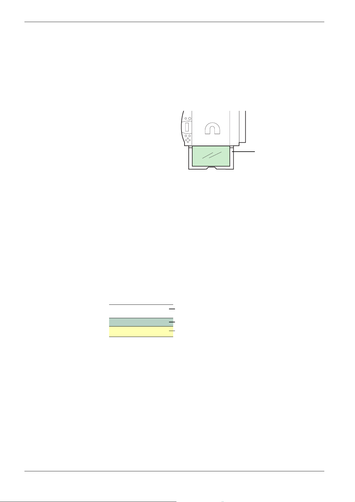
2.4 Special Paper
Transparency
Transparencies for overhead projectors must withstand the heat of fusing during the printing
process. The recommended transparency product is as follows:
3M CG3700 (Letter, A4)
Transparencies must be placed on the MP (multi-purpose) tray with the long edge towards
the printer. To avoid problems, stack transparencies face up on the face-up tray.
MP Tray
Figure 2-10
When unloading transparencies (e.g., for clearing jams), hold them carefully by the edges to
avoid leaving fingerprints on them.
Adhesive-backed labels
Label paper must be fed manually.
For printing on labels, use extreme care so that the adhesive may not come in direct contact
with any part of the printer. Adhesives that stick to the drum or rollers will cause printer
damage.
Labels consist of three parts. Printing is done onto the top sheet (also called the face sheet).
The adhesive contains chemicals. The carrier sheet (also called the backing paper or liner)
bears the top sheet. This composition of labels can cause more problems than other print
forms during printing.
Top sheet (white bond paper)
Adhesive
Carrier sheet
Figure 2-11
When using label paper, do not leave gaps between the arranged labels (i.e., top sheets).
Labels arranged with gaps in-between can easily be peeled off during printing, causing
serious jam problems.
2-12
Page 44

2.4 Special Paper
When the label paper has extra margin around the label’s outside edges that correspond to
the margins of the printable area, do not remove the extra top sheet from the carrier sheet
until printing is finished.
Not allowedAllowed
Top sheet
Carrier sheet
Figure 2-12
When selecting labels, make sure to use only those meeting the following requirements:
Item Value
Top sheet weight 44 to 74 g/m² (12 to 20 lb)
Total weight 104 to 151 g/m² (28 to 40 lb)
Top sheet thickness 0.086 to 0.107 mm (3.9 to 4.2 mils)
Total thickness 0.115 to 0.145 mm (4.5 to 5.7 mils)
Moisture content 4 to 6 % (composite)
T able 2-6
Postcards
Fan the stack of postcards and align the edges before loading them in the MP tray. Make
sure the postcards you are going to set are not curled. Feeding curled postcards may cause
paper jams.
Some postcards have rough edges on the back (those are created when the paper is cut). In
this case, put the postcards on a flat place and rub the edges with, for example, a ruler to
smooth them.
Figure 2-13
2-13
Page 45

2.4 Special Paper
Envelopes
Envelopes must be fed manually.
Since the composition of an envelope is more complex than that of ordinary paper, it is not
always possible to ensure consistent printing quality over the entire envelope surface.
Normally, envelopes have a diagonal grain direction. See section Grain on page 2-6. This
direction can easily cause wrinkles and creases when envelopes pass through the printer.
Before purchasing envelopes, make a test print to check whether the printer accepts the
envelope.
Other handling cautions follow:
• Do not use envelopes that have an encapsulated liquid adhesive.
• A void a long printing session for envelopes only. Extended envelope printing can cause
premature printer wear.
• To avoid jams caused by curled envelopes, stack the printed envelopes no higher than
10 on the output tray.
Colored paper
Colored paper should have the same specifications as the white bond paper listed. In
addition, the pigments in the paper must be able to withstand the heat of fusing durin g the
printing process (up to 200
C or 392 °F).
°
Note
Pre-printed paper
Pre-printed paper should basically be bond paper. The inks on the paper must be able to
withstand the heat of fusing during the printing process and must not be adversely affected
by silicon oil. Do not use paper with any kind of coating, such as calendar stock.
Recycled paper
Select recycled paper that has the same specifications as white bond paper . See
page 2-2
Before purchasing recycled paper, make a test using the printer and check whether
the print quality is satisfactory.
. Recycled paper, however, does not have to be as white as white bond paper.
Table 2-1 on
2-14
Page 46

Chapter 3 Using the Operator Panel
This chapter provides the information you need to configure the Ecosys Color printer. In
general you need to use the operator panel only to make default settings. Y ou can make most
changes to the printer settings using the printer driver trough the application software.
Changes to printer settings made using a software application override changes made
using the operator panel.
Note
You can also rely on other printer utilities such as Kyocera Mita PrintMonitor if you need to
change settings that are not available on the printer driver. It will allow you remotely access
to printer settings. Printer utilities are supplied in the CD-ROM supplied with the printer.
The chapter describes the operator panel in detail, including its menus and the procedures
for changing various printer settings.
Page 47
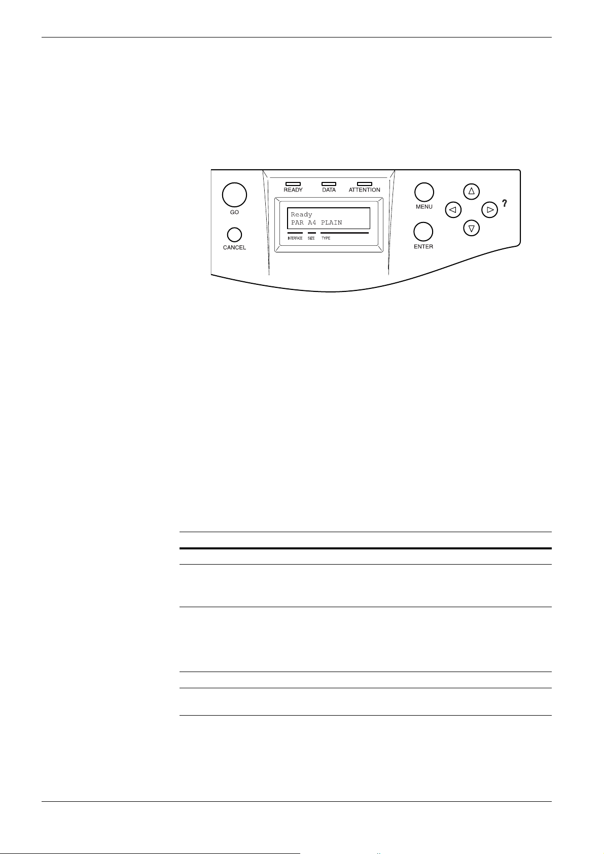
3.1 Understanding the Operator Panel
3.1 Understanding the Operator Panel
The operator panel on the top of the printer has a 2-line by 16-character liquid crystal
display (LCD), eight keys, and three indicators (LED).
Figure 3-1
Messages that appear on the display and functions of indicators and keys are explained in
the sections that follow.
3.1.1 Message Display
The message display on the operator panel shows:
• Status information, the eight messages listed below which are displayed during normal
operation.
• Error codes, when the printer requires the operator’s attention; as explained in
Chapter 4 Troubleshooting.
Status Information
Message Meaning
Self test The printer is performing self-diagnostics after power-up.
Please wait The printer is warming up and is not ready.
When the printer is switched on for the first time, this messa ge
will take several minutes.
Please wait
(Calibrating)
Ready The printer is ready to print.
Processing The printer is receiving data to print. This is also shown when the
The color calibration function is being performed automatically
as you powered on the printer.
You can also execute this function manually on the operator
panel. For details, see Section 3.13.12 Color Calibration on page
3-100.
printer is reading a memory card or hard disk.
T able 3-1
3-2
Page 48

3.1 Understanding the Operator Panel
Message Meaning
Sleeping The printer is in sleep mode. The printer wakes from sleep mode
whenever a key on the operator panel is pressed, the cover is
opened or closed, or a print job is received. The printer then
warms up and goes on-line. For details on sleep mode, see Sleep
Timer Timeout Time on page 3-91.
Cancelling data Jobs inside the printer are being canceled. To cancel a job, see
Section 3.1.3 Keys on page 3-6.
Waiting The printer is waiting for the rest of print job before completing
the last page. Pressing the GO key allows you to obtain the last
page immediately. See below.
FormFeed TimeOut The printer is printing the last page after a waiting period.
Table 3-1 (Continued)
Error codes
See
Chapter 4 Troubleshooting
3.1.2 Indicators in Message Display
Figure 3-2
Interface Indicator (INTERFACE)
The interface indicator shows the interface that is currently in use:
PAR Parallel interface is in use.
USB USB interface is in use.
SER Serial (RS-232C) interface is in use. (option)
NET Network interface is in use.
OPT Network interface is in use. (option)
--- No interface is in use.
.
Each interface has a timeout time of 30 seconds during which the other interface should wait
to receive a print job. Even a print job has been complete on the interface, you should wait
for this period until the other interface begins printing the job.
3-3
Page 49

3.1 Understanding the Operator Panel
Paper Size Indicator (SIZE)
This indicator indicates:
• While the printer is in standby, the paper size of the cassette. The default paper cassette
is determined by the operator panel keys. For details, see
Section 3.10 Paper Handling
on page 3-69.
• While the printer is printing, the paper size used to format the document to print by the
application software.
The abbreviations used to indicate the paper sizes and their dimensions are as follows:
A3 ISO A3 (29.7 × 42 cm)
A4 ISO A4 (21 × 29.7 cm)
A5 ISO A5 (14.8 × 21 cm)
A6
ISO A6 (10.5 × 14.8 cm)
B4 JIS B4 (25.7 × 36.4 cm)
B5 JIS B5 (18.2 × 25.6 cm)
B6
JIS B6 (12.8 × 18.2 cm)
LT Letter (8-1/2 × 11 inches)
LD Ledger (11 × 17 inches)
LG Legal (8-1/2 × 14 inches)
MO
BU
DL
C4
C5
b5
EX
#6
#9
HA
OH
O2
a3
ld
8K
16K
ST
FO
Y2
Y4
CU
Monarch (3-7/8 × 7-1/2 inches)
Business (4-1/8 inches)
ISO DL (11 × 22 cm)
ISO C4 (22.9 × 32.4 cm)
ISO C5 (16.2 × 22.9 cm)
ISO B5 (17.6 × 25 cm)
Executive (7-1/4 × 10-1/2 inches)
Commercial 6-3/4 (3-5/8 × 6-1/2 inches)
Commercial 9 (3-7/8 × 8-7/8 inches)
Japanese Postcard (10 × 14.8 cm)
Return Postcard (20 × 14.8 cm)
Oficio II (8-1/2 × 13 inches)
A3 Wide (31× 43.2 cm)
Ledger Wide (31× 44 cm)
8 kai (27.3 × 39.4 cm)
16 kai (19.7 × 27.3 cm)
Statement (5-1/2 × 8-1/2 inches)
Folio (21 × 33 cm)
Yokei 2 (11.4 × 16.2 cm)
Yokei 4 (10.5 × 23.5 cm)
Custom Size (8 × 14.8 cm to 31 × 45.8 cm)
†
†
†
†
†
†
†
†
†
†
†
†
†
†
†
†
†
†
†
†
†
†
†
† Only with MP tray feeding
3-4
Page 50

3.1 Understanding the Operator Panel
Paper Type Indicator (TYPE)
This indicator shows the paper type defined for the current paper casette. The paper type can
be manually defined using the operator panel. For more information, see
Section 3.10 Paper
Handling on page 3-69.
The following abbreviations are used:
(none) Auto
PLAIN Plain paper
TRNSPRNCY
Transparency
PREPRINTE Pre-printed paper
LABELS
Labels
BOND Bond paper
RECYCLED Recycled paper
VELLUM
Vellum
ROUGH Rough paper
LETTERHEA Letterhead
COLOR Colored paper
PREPUNCH Pre-punched paper
ENVELOPE
CARDSTOCK
Envelope
Card stock
COATED Coated paper
THICK Thick paper
CUSTOM1 (to 8) Custom 1 (to 8)
†
†
†
†
†
† Only with MP tray feeding
READY, DATA, and ATTENTION Indicators
The following indicators light during normal operation and whenever the printer needs
operator’s attention. Depending on the status of lighting, each indicator has the following
meaning:
Indicator Description
READY
DATA
ATTENTION
Flashing. Indicates an error that you can recover by yourself, such as
the loose front cover. For details, see Chapter 4 Troubleshooting, sec-
tion 4.3 Error Messages on page 4-6
.
On. Indicates that the printer is ready and o n-line. The printer prints the
data it receives.
Off. Indicates that the printer is off-line. Data can be received but will
not be printed until the printer is on-line by pressing the GO key. Also,
indicates when printing is automatically stopped due to the occurrence
of an error. For details see Chapter 4 Troubleshooting, section 4.3 Error
Messages on page 4-6.
Flashing. Indicates that a data is being received from the computer.
On. Indicates either that data received is being processed before print-
ing starts, or that data received is being written to a memory card or a
hard disk.
Flashing. Indicates that the printer requires maintenance or is warming up.
On. Indicates the occurrence of a problem or an error. For details, see
Chapter 4 Troubleshooting, section 4.3 Error Messages on page 4-6.
T able 3-2
3-5
Page 51

3.1 Understanding the Operator Panel
3.1.3 Keys
Note
The operator panel keys are used to configure the printer operation. Note that certain keys
have the secondary function.
The printer has a parallel, serial, and an option al network interface. Configuration to
the printer settings made with these keys affect only one of these interfaces that is
currently active (indicated by the INTERFACE indicator on the message display). See
Interface Indicator (INTERFACE) on page 3-3.
GO Key
The GO key switches the printer between on-line and off-line. Use this key to:
• T oggle the printer’ s on-line and off-line states. You can temporarily stop the print job by switching
the printer off-line.
• Print and feed out one page when the printer displays Waiting.
• Recover from certain errors
CANCEL Key
This key is used to:
• Cancel a printing job
• Stop the alarm sound
• Reset numeric values or cancels a setting procedure while using menu system
To cancel a printing job:
While the printer displays Processing, press the CANCEL key.
1111
Print Cancel? appears on the message display followed by the interface which
the job to cancel is on. The interface is indicated by one of the following message:
Parallel
USB
Network
Serial (option serial interface)
Option (option network interface)
Press the ENTER key. Cancelling data appears on the message display and
2222
printing stops after the current page is printed.
3-6
Page 52

3.1 Understanding the Operator Panel
MENU Key
The MENU key lets you enter the menu system to change the setup and printing
environment of the printer.
Pressing this key during a menu selection will terminate the selection and return the printer
to the normal operation.
Arrow Keys
The four arrow keys are used in the menu system to access a desired item or enter numeric
values.
Note
The arrow key with the question mark (?) may be pressed when the paper jam message has
appeared on the message display. Then a help message will appear to facilitate jam clearing
in the location.
ENTER Key
This key is used to:
• Finalize settings of numeric values and other selections.
• Set the paper source when Use alternative? is shown in the message display.
If you hold down the ENTER key and press the MENU key when Ready is shown on
this printer, the AdministrationID menu will be displayed. This menu is the setting
menu for administration under the Account Management Syste m and is no rma ll y no t
used. Press the MENU key to return to the Ready display.
3-7
Page 53
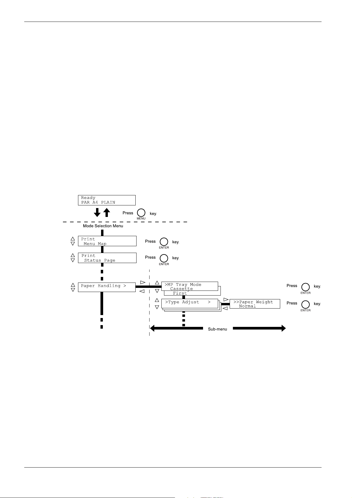
3.2 Using the Menu Selection System
3.2 Using the Menu Selection System
3.2.1 Menu Selection System
This section explains how to use the menu selection system. The MENU key on the operator
panel allows you to use the menu to set or change the printer environment such as the
number of copies to print, emulation, etc., to your specific needs. Settings can be made
when Ready is indicated on the printer message display.
The printer obeys the most recently received printer settings sent from the application
software, or from the printer driver, which take priority over operator panel settings.
Entering the Mode Selection Menu
Press the MENU key when Ready is indicated on the printer message display.
The mode selection menu is displayed.
3-8
Page 54

3.2 Using the Menu Selection System
Selecting a Menu
The mode selection menu is hierarchical. Press the U or V key to display the desired menu.
• If the selected menu has a sub-menu, > is displayed after the menu.
Paper Handling >
Indicates that there is a sub-menu
Press the Z key to move to the sub-menu or Y key to go back.
• > is displayed before the sub-menu.
Indicates that this is the sub-menu
>Type Adjust >
Indicates that there is another sub-menu
Press the Z key to move to another sub-menu or Y key to go back.
• >> is displayed before the second sub-menu.
Indicates that this is the second sub-menu
>>Paper Weight
Normal
Note
Setting a Menu
Select the desired menu and press the ENTER key to set or change the configuration.
Press the U or V key to display the desired item and the ENTER key to finalize the value
or selections set.
Cancelling Menu Selection
If you press the MENU key when selecting a menu, the message display returns to Ready.
Settings that are received from application software and the printer driver will take
priority over settings made in the operator panel.
3-9
Page 55

3.2 Using the Menu Selection System
3.2.2 Menu System Road Map
The following is the hierarchy diagram of the menu selection system of the printer.
For details about menu selection operations, see page 3-8.
Ready
PAR A4 PLAIN
Print
Menu Map
Print
Status Page
e-MPS >
MENU Key
>Quick Copy
>Private/Stored
Continued on the next page
>Print VMB Data
>List of VMB
>List of
Code JOB
>e-MPS >
Configuration
>>Quick Copy
32
>>Temp. Code JOB
Size 1550MB
>>Perm. Code JOB
Size 1550MB
>>VMB Size
1550MB
3-10
Page 56

Continued
3.2 Using the Menu Selection System
Interface >
Parallel
Interface
USB
Interface >
Network
Interface >
Serial
Interface >
Option
>Parallel I/F
Nibble (high)
>NetWare
Off
>NetWare >
On
>TCP/IP
Off
>TCP/IP >
On
>EtherTalk
Off
>EtherTalk
On
>Network Status
Page Off
>Network Status
Page On
>Baud Rate
9600
>Data Bits
8
>Stop Bits
1
>Parity
None
>Protocol
DTR (pos.)&XON
>>NetWare Frame
Auto
>>DHCP
Off
>>DHCP
On
>>IP Address
000.000.000.000
>>Subnet Mask
000.000.000.000
>>Gateway
000.000.000.000
Emulation
PCL 6
Emulation >
KC-GL
Emulation >
KPDL
Emulation >
KPDL (AUTO)
Continued on the next page
>NetWare
Off
>NetWare >
On
>TCP/IP
Off
>TCP/IP >
On
>EtherTalk
Off
>EtherTalk
On
>Opt. StatusPage
On
>Opt. StatusPage
Off
>KC-GL Pen >
Adjust Pen (1)
>KC-GL Page Set
[SPSZ]
>Print KPDL errs
Off
>Print KPDL errs
On
>Alt. Emulation
PCL 6
>Print KPDL errs
Off
>Print KPDL errs
On
>>NetWare Frame
Auto
>>DHCP
Off
>>DHCP
On
>>IP Address
000.000.000.000
>>Subnet Mask
000.000.000.000
>>Gateway
000.000.000.000
>>Pen(1) Width
01 dot(s)
>>Pen(1) Color
Black
3-11
Page 57

3.2 Using the Menu Selection System
Continued
Font >
Page Set > >Copies
Print Quality >
>Font Select >
Internal
>Font Select >
Option
>Code Set
IBM PC-8
>List of
Internal Fonts
>List of
Option Fonts
001
>Orientation
Portrait
>Orientation
Landscape
>Page Protect
Auto
>Page Protect
On
>LF Action
LF only
>CR Action
CR only
>Tone
Normal
>Tone
Fine
>Gloss Mode
Low
>Gloss Mode
High
>> I000
>>Courier
Regular
>>Courier
Dark
>>Letter Gothic
Regular
>>Letter Gothic
Dark
>>Size
012.00 point(s)
>>Pitch
10.00 cpi
Opt. ROM >
>Read Data
>List of
Partitions
Hard Disk > >Read Data
>Write Data
>Delete Data
>Format
>List of
Partition
RAM Disk Mode
Off
RAM Disk Mode >
On
>RAM Disk Size
>Read Data
>Write Data
>Delete Data
>List of
Partition
Continued on the next page
3-12
Page 58
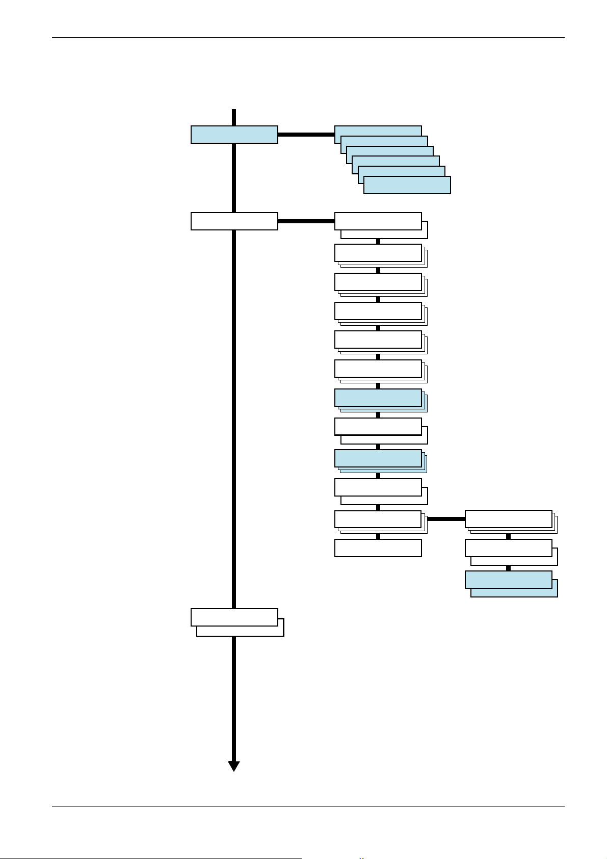
Continued
3.2 Using the Menu Selection System
Memory Card >
Paper Handling >
>Read Fonts
>Write Data
>Write Data
>Delete Data
>Format
>List of
Partition
>MP Tray Mode
Cassette
>MP Tray Mode
First
>MP Tray Size
A4
>MP Tray Type
Plain
>Cassette 1 Type
Plain
>Cassette 2 Type
Plain
>Feed Select
Cassette 1
>Duplex Mode
None
>Stack Select
Facd-down tray
>Stack Select
Facd-up tray
>Sorter Mode
Sorter
Color Mode
Color
Color Mode
Monochrome
Continued on the next page
>Override A4/LT
Off
>Override A4/LT
On
>Type Adjust >
Custom 1
>Reset Type
Adjust
>>Paper Weight
Normal
>>Fuser Mode
Low
>>Fuser Mode
Middle
>>Duplex Path
Enable
>>Duplex Path
Disable
3-13
Page 59
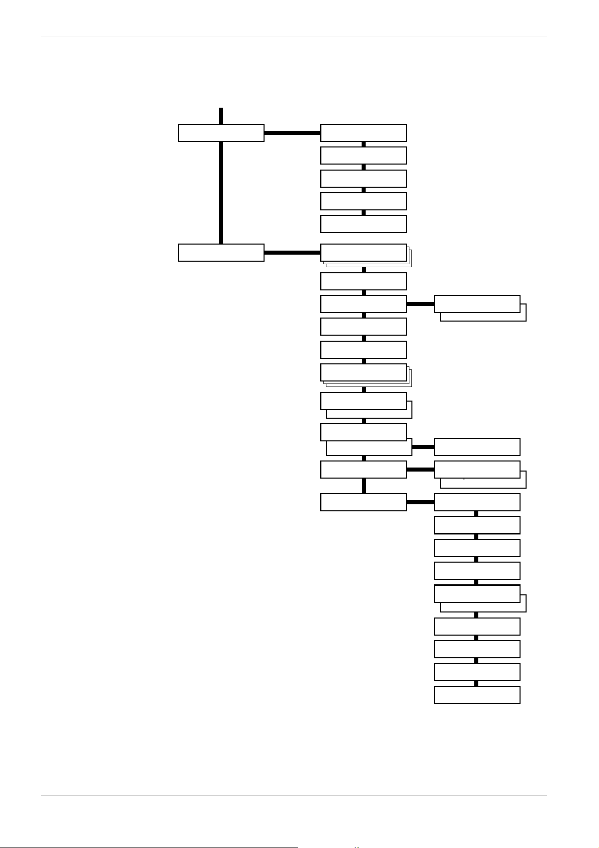
3.2 Using the Menu Selection System
Continued
Life Counters > >Total Print
>New Toner [C]
Installed
>New Toner [M]
Installed
>New Toner [Y]
Installed
>New Toner [K]
Installed
Others >
>MSG Language
English
>Form Feed
Time Out 000sec.
>Sleep Timer >
030 min.
>Print HEX-DUMP
>>Sleep Mode
On
>>Sleep Mode
Off
>Printer Reset
>Resource Prot.
Off
>Buzzer
Off
>Buzzer
On
>Auto Continue
Mode Off
>Auto Continue >
Mode On
>Finishing >
Error
>Service > >>Print Status
>>Auto Continue
Timer 030sec.
>>Duplex
On
>>Duplex
On
Page
>>Color
Calibration
>>Print Test
Page 1
>>Print Test
Page 2
>>Dehumidifier
Off
>>Dehumidifier
On
>>Maintenance
[A]
>>Maintenance
[B]
>>Maintenance
[C]
>>Drum
3-14
Page 60

3.3 Menu Map and Status Pages
This section explains the procedure for printing the printer’s internal information using the
menu selection system. The menu map is usefull as a reference to guide yourself through the
menu selection system.
The status page is a list of parameters and settings for most basic printer configurations. You
may be required to produce a status page when requesting service to the printer.
3.3.1 Printing a Menu Map
The printer prints a full list of menu selection system — Menu Map. Note that menus shown
in the list may vary depending on which optional units installed in the printer.
Press the MENU key.
1111
Press the U or V key repeatedly until Print Menu Map appears.
2222
3.3 Menu Map and Status Pages
Print
Menu Map
Press the ENTER key. A question mark (?) appears.
3333
Print
Menu Map ?
Press the ENTER key. The message Processing appears and the printer prints a
4444
Menu Map.
3-15
Page 61
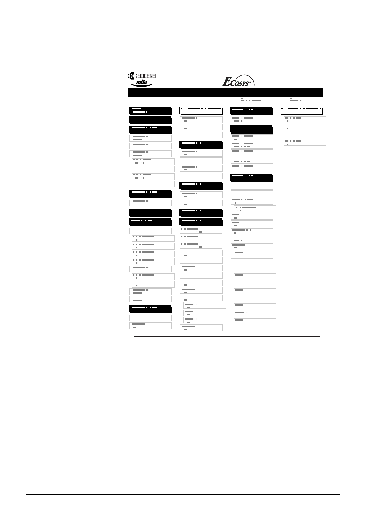
3.3 Menu Map and Status Pages
FS-C8008N Page Printer
MENU MAP
Figure 3-3
3-16
Page 62

3.3.2 Printing a Status Page
You can check the printer’s current status, including available memory space and option
settings by printing a status page.
Press the MENU key.
1111
Press the U or V key repeatedly until Print Status Page appears.
2222
Press the ENTER key. A question mark (?) appears.
3333
3.3 Menu Map and Status Pages
Print
Status Page
Print
Status Page ?
Press the ENTER key again. The message Processing appears and the printer
4444
prints a status page.
For a sample status page and its full description, see Understanding the Status Page
on page 3-18.
3-17
Page 63
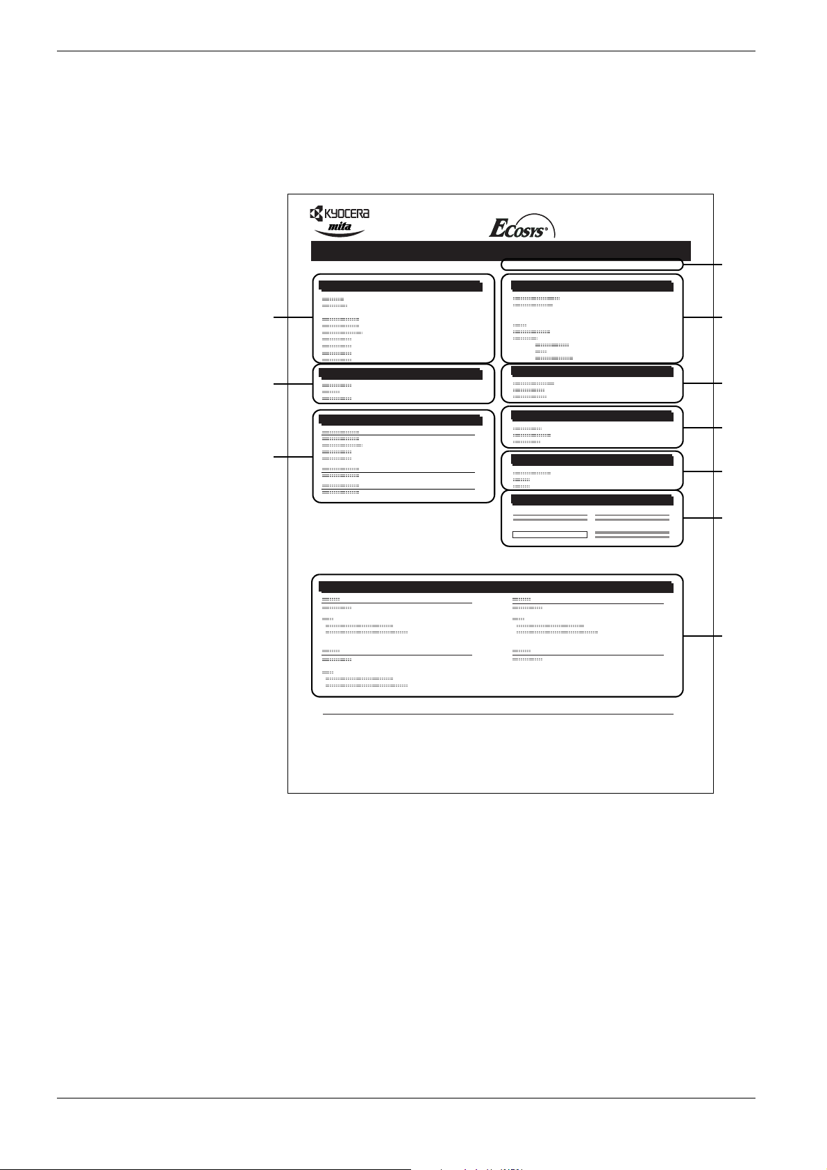
3.3 Menu Map and Status Pages
Understanding the Status Page
The numbers in the following diagram refer the items explained below the diagram. The
items and values on the status page may vary depending on the printer’s firmware version.
FS-C8008N Page Printer
STATUS PAGE
Hardware Information
Firmware Version: Released:
Memory
1
2
Page Information
Installed Options
4
Network Status
6
Emulation
Error Log
3
5
7
8
Consumable Status
9
Interfaces
10
Figure 3-4
1 Software Version
This item shows the version and release date of the printer firmware.
2 Hardware Information
This item shows various printer settings for hardware-related items:
• MP tray paper size and type
• Paper cassette size and type
• Draft mode
• Buzzer control
• Host buffer size
• Sleep time timeout time
• Formfeed timeout time
3-18
Page 64

3Memory
This item shows:
• Standard memory in the printer (128 MB)
• Option memory slot status (Slots 1 and 2) in megabytes
• Total memory in the printer
• Current status of the RAM disk
4 Page Information
This item shows the page related items:
• Tone mode, Normal or Fine
• Number of copies, from 1 to 999
• Total page count
5 Installed Options
This item shows the options installed in the printer:
• Hard disk
• Option ROM
• Memory card
3.3 Menu Map and Status Pages
6 Network Status
This item shows the IP address, subnet mask address, and default gateway address for
the network interface card in the printer.
7Emulation
This item shows all available emulations of the printer. The PCL 6 emulation is set as
default when the printer is shipped from the factory. The emulations are:
•PCL 6
•KPDL3
•KC-GL
8 Error Log
This item shows the last three instances of the following types of errors, listing them in
the order of occurrence:
• KPDL (PostScript) errors
• Memory overflow
• Print overrun
• File-not-found
The most recent error is displayed on the topmost line of Error Log. Error information
is cleared when the printer is powered off.
The error log information is intended for service purpose.
9 Consumable Status
This item shows the approximate level of remaining toner. When the value is 100, the
toner container is full. The closer to 0, the smaller the amount of remaining toner.
10 Interface Information
This information shows the emulation and the default font for all interfaces installed in
the printer.
3-19
Page 65

3.4 e-MPS
3.4 e-MPS
e-MPS is an abbreviation for ‘enhanced-Multiple Printing System’ which implements the
following functions that are available from the printer driver:
• Job Retention
• Job Storage
In either job mode, when printing a document, the print data is transferred from the
computer to the printer then stored on the printer’s hard disk. Since copies of the document
are printed using the stored data, printing is performed faster with less computer spooling
time and less network traffic.
• To use the e-MPS system, the standard hard disk must be installed in the printer.
For details, see Appendix A Options.
Note
• The RAM disk may also be used in the Proof-and-Ho ld and Private Print modes.
See Using the RAM Disk on page 3-67 for details on RAM disk setup.
Job Retention
Job Retention has four modes as summarized below. These modes are selected when you
choose on the printer driver through the application software:
Quick Copy Proof-and-Hold Private Print Stored Job
Primary function To later print addi-
tional copies
Start storing by Printer driver Printer driver Printer driver Printer driver
On terminating
print setting from
application software
Retrieved by Operator panel Operator panel Operator panel Operator panel
Default number of
copies printed at
retrieval
Maximum number
of jobs stored
PIN security No No Yes Yes (if necessary)
Data after printing Stored Stored Deleted Stored
Data at power off Deleted Deleted Deleted Stored
Hard disk required Yes No No Yes
Prints simultaneously
Same as storing
(can be changed)
32, expandable to
†
50
To proof the first
copy before printing multiple copies
Prints one copy
simultaneously
One less
(can be changed)
32, expandable to 50Depends on the
To hold the document in printer to
prevent unauthorized access
Does not print Does not print
Same as storing
(can be changed)
hard disk capacity
(Private jobs are
deleted automatically once it is
retrieved.)
To electronically
store documents
such as fax cover
pages
One
Depends on the
hard disk capacity
T able 3-3
† Jobs in excess will cause the earlier ones to be deleted.
3-20
Page 66

Note
3.4 e-MPS
Job Storage
Job storage stores print jobs either temporarily or permanently, or in virtual mailboxes, as
you click an appropriate radio button on the printer driver when printing from a computer.
Virtual Mailbox
Virtual mailbox is part of Job Storage, which stores print jobs on the hard disk without
printing. It enables you to retrieve jobs later from the operator panel or the KM-NET
Printer Disk Manager utility in the CD-ROM.
Each mailbox may be used by an individual who desires to share the printer in this mode.
By default, each mailbox is numbered from ‘Tray 001,’ ‘Tray 002,’ ... etc. To ‘post’ a job in
one of these mailboxes, you assign a numbered or named mailbox on the printer driver
when printing.
To retrieve the stored job for printing, see Retrieving Jobs from Virtual Mailbox (VMB) on
page 3-28.
The virtual mailbox can be used in PCL 6 emulation only.
3.4.1 Using Quick Copy
This mode enables you to print the requested number of copies of a job, simultaneously
storing the job on the hard disk. When additional copies are required, you can reprint the
required number of copies from the printer operator panel. To print a job as a quick copy
job, see KX Printer Drivers Operation Guide.
The default number of print jobs that can be stored on the hard disk is 32. This value can be
increased to up to 50 from the e-MPS Configuration menu. For details, see Changing the
Maximum Number of Quick Copy/Proof-and-Hold Jobs on page 3-30
jobs reaches the limit, the oldest job will be overwritten by the new one.
When the printer is turned off, all stored jobs will be deleted.
. When the number of
3-21
Page 67

3.4 e-MPS
Printing Additional Copies using Quick Copy
To print additional copies of a job stored in the printer:
Press the MENU key.
1111
Press the U or V key repeatedly until e-MPS > appears.
2222
e-MPS >
Press the Z key.
3333
Press the U or V key repeatedly until >Quick Copy appears followed by the user
4444
name (Harold, in this example). The user name is assigned at printing using the
printer driver.
>Quick Copy
Harold
Press the ENTER key. A blinking question mark (?) appears before the user name.
5555
>Quick Copy
?Harold
Press the U or V key to display the desired user name, Arlen, in this example.
6666
>Quick Copy
?Arlen
Press the ENTER key. The job name entered in the printer driver (Report, in this
7777
example) appear with a blinking question mark (?) before the letters.
>Arlen
?Report
Press the U or V key to scroll to the desired job title.
8888
Press the ENTER key . The number of copies to be printed can be set. To increase the
9999
copy count, press the U key; to decrease the copy count, press the V key.
>Report
Copies 001
Press the ENTER key to finalize the copy count. The printer prints the specified
10
10
1010
number of copies for the job.
3-22
Page 68

3.4 e-MPS
Deleting a Quick Copy Job
All quick copy jobs are automatically deleted when the printer is turned off. If you desire to
explicitly delete a stored quick copy job, proceed as follows:
Follow steps 1 through 8 in the above section to let the title of the job to be deleted
1111
displayed.
When the title of the job to be deleted is displayed, e.g. Report, below, press the
2222
ENTER key. The cursor below the copy coun t starts to blink.
>Report
Copies 001
Press the V key repeatedly until Delete appears below the title.
3333
>Report
Delete
4444
3.4.2 Using Proof-and-Hold
When you print multiple copies, this mode first prints one copy so that you can proof it
before continuing to print the remaining copies. Since you can proof the printouts before
printing the remaining copies, wastage of paper can be reduced.
The printer prints one copy and, at the same time, saves the print job on the hard disk/RAM
disk. You can also change the number of copies when resumin g printing from the operator
panel.
When the printer is turned off, all stored jobs will be deleted.
Printing Remaining Copies of a Proof and Hold Job
Printing a Proof-and-Hold job on the operator panel is similar to printing a quick copy job.
See
Printing Additional Copies using Quick Copy on page Chapter 3-22
Press the ENTER key. The stored quick copy job is deleted.
.
3-23
Page 69

3.4 e-MPS
3.4.3 Printing a Private Print/Job Retention
In private printing, you can specify that a job is not printed until you release the job from the
operator panel. At sending the job from the application software, you can specify a 4-digit
access code in the printer driver. The job is releas ed for printing by entering the access code
on the operator panel. Thus, this function ensures confidentiality of the print job.
In the job retention mode, access codes are not mandatory, but can be set on the printer
driver if printing with the PIN security is required. Then, the access code must be entered on
the operator panel to print a stored job. Print data will be stored in the hard disk/RAM disk
after printing. See KX Printer Drivers Operation Guide for the driver settings.
Releasing a Private/Stored Job
Press the MENU key.
1111
Press the U or V key repeatedly until e-MPS > appears.
2222
e-MPS >
Press the Z key.
3333
Press the U or V key repeatedly until >Private/Stored appears. The name
4444
entered in the printer driver (Harold, in this example) also appears.
>Private/Stored
Harold
Press the ENTER key. A blinking question mark (?) appears before the user name.
5555
>Private/Stored
?Harold
Press the U or V key to display the desired user name (Arlen, in this example).
6666
>Private/Stored
?Arlen
Press the ENTER key. The user name and the job name (Agenda, in this example)
7777
entered in the printer driver appear with a blinking question mark (?).
>Arlen
?Agenda
Press the U or V key to display the desired job title.
8888
3-24
Page 70

Press the ENTER key. The ID input line appears. Enter the four-digit access code
9999
entered in the printer driver and press the ENTER key.
>Agenda
ID 0000
To enter the ID, press the Y or Z key to move the cursor to the number to be
changed and then enter the correct number by pressing the U or V key.
You can set the number of copies to be printed. To increase the copy count, press the
10
10
1010
U key; to decrease the copy count, press the V key.
>Agenda
Copies 001
Press the ENTER key to finalize the copy count. The printer prints the specified
11
11
1111
number of copies for the job.
3.4 e-MPS
Deleting a Private/Stored Job
You can individually delete stored jobs by performin g the following procedure. Jobs saved
using Private Print will be automatically deleted if you turn the power off after printing, but
jobs saved using Stored Job will not be deleted automatically.
Follow steps 1 through 8 in the above section.
1111
When the title of the job to be printed is displayed (Agenda, in this example), press
2222
the ENTER key. Enter the four-digit access code entered in the printer driver and
press the ENTER key.
>Agenda
Copies 001
Press the V key repeatedly until Delete appears for the number of copies.
3333
>Agenda
Delete
Press the ENTER key. The private job is deleted from the hard disk.
4444
3-25
Page 71

3.4 e-MPS
Printing a Code Job
Install the KM-NET Job Manager software from the CD-ROM supplied with the printer. To
do this, from the CD-ROM Main Menu, select Printer Utilities > Install KM-NET Job
Manager.
Browse through Windows Start > Programs > KYOCERA MITA > KM-Net >
1111
Job Manager.
Enter the password for the software. Job Manager will start.
2222
Click the Add printer icon (below). Select the Local or Network port.
3333
If you use the local parallel port to connect to the printer, make sure
that the printer driver is set to print to a local port. To check this out,
Note
Add printer
icon
click the Details tab of the printer Properties, and note the Print to the
following port setting.
Follow the wizard until the Select printer dialog box is reached. When the printer
4444
is found in the Printer List, click (highlight) it, then Finish.
Double click Model Name on the list. The jobs currently stored in the printer are
5555
shown. To print the job, right click Job name and then click Print on the drop
down list that appears.
It is possible to select more than one job at a time by left clicking a job one by one
while pressing the Ctrl key on the computer keyboard.
The job remains intact even after printing. To permanently delete the job in the hard disk,
right click the job name on Job Manager, then click Delete on the drop down list that
appears.
3-26
Page 72

3.4 e-MPS
Printing a List of Code Jobs
If you select Permanent Job Storage on the printer driver, you can have a List of Code Job
printed using the operator panel.
Press the MENU key.
1111
Press the U or V key repeatedly until e-MPS > appears.
2222
e-MPS >
Press the Z key.
3333
Press the U or V key repeatedly until >List of Code JOB appears.
4444
>List of
Code JOB
Press the ENTER key. A question mark (?) appears.
5555
>List of
Code JOB ?
Press the ENTER key again. The printer prints a Code Job list as shown in
6666
Figure 3-5 below.
FS-C8008N Page Printer
PERMANENT CODE JOB LIST
Figure 3-5
3-27
Page 73

3.4 e-MPS
3.4.4 Retrieving Jobs from Virtual Mailbox (VMB)
To retrieve the jobs posted in the virtual mailbox, proceed as follows.
Press the MENU key.
1111
Press the U or V key repeatedly until e-MPS > appears.
2222
e-MPS >
Press the Z key.
3333
Press the U or V key repeatedly until >Print
4444
mailbox number will also appear.
>Print VMB Data
Tray001
:
VMB
Data appears. The virtual
If you have named the virtual mailbox with an alias on the printer driver, the alias
(Richard, in this example) will follow the number:
>Print VMB Data
Tray001
Press the ENTER key. A blinking question mark (?) appears.
5555
>Print VMB Data
Tray001
Press the ENTER key. The document in the mailbox is printed and automatically
6666
deleted from the mailbox.
Printing a List of VMB
A Virtual Mailbox list includes the jobs currently stored in the mailboxes.
Press the MENU key.
1111
:Richard
?Richard
Press the U or V key repeatedly until e-MPS > appears.
2222
e-MPS >
Press the Z key.
3333
3-28
Page 74
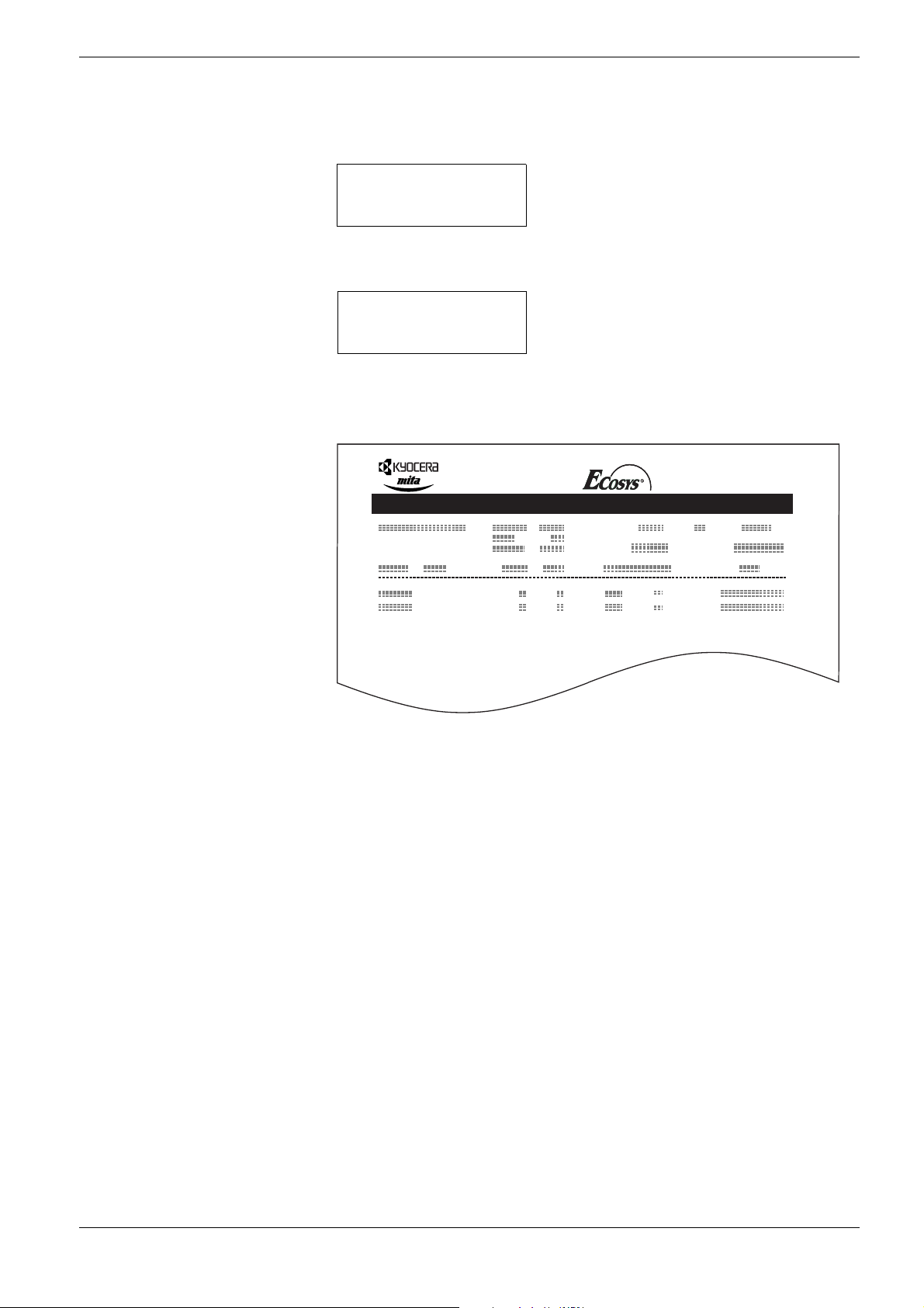
Press the U or V key repeatedly until >List of VMB appears.
4444
>List of VMB
Press the ENTER key. A question mark (?) appears.
5555
>List of VMB ?
Press the ENTER key again. The printer prints a list of jobs currently posted in the
6666
virtual mailboxes as shown in Figure 3-6 below.
FS-C8008N Page Printer
VIRTUAL MAIL BOX LIST
3.4 e-MPS
Figure 3-6
3-29
Page 75
3.4 e-MPS
3.4.5 Changing e-MPS Configuration
You can change the following parameters for e-MPS operation:
• Maximum number of Quick Copy/Proof-and-Hold jobs
• Maximum space assigned to temporary code jobs
• Maximum space assigned to permanent code jobs
• Maximum space assigned to virtual mailboxes
The total amount of storage areas specified must not exceed the total size of the hard
disk. Otherwise, you may only be able to accommodate print jobs of a smaller amount
Note
of print jobs than specified.
Changing the Maximum Number of Quick Copy/Proof-and-Hold Jobs
This changes maximum number of Quick Copy/Proof-and-Hold jobs from 0 to 50. The
default is 32.
Press the MENU key.
1111
Press the U or V key repeatedly until e-MPS > appears.
2222
e-MPS >
Press the Z key.
3333
Press the U or V key repeatedly until >e-MPS Configuration > appears.
4444
>e-MPS >
Configuration
Press the Z key.
5555
Press the U or V key repeatedly until >>Quick Copy appears.
6666
>>Quick Copy
32
Press the ENTER key. A blinking cursor (_) appears.
7777
>>Quick Copy
32
Press the U or V key to increase or decrease the value at the blinking cursor. The
8888
value can be set between 0 and 50. Use the Z and Y keys to move the cursor right
and left.
When the desired maximum number of jobs is set, press the ENTER key.
9999
3-30
Page 76

3.4 e-MPS
Press the MENU key. The display returns to Ready.
10
10
1010
Maximum Space Assigned to Temporary Code Jobs
This changes the hard disk space that holds temporary code jobs. You can change the
maximum space from 0 to 9999 (megabytes). The actual maximum size depends on the size
of free hard disk space, however. The default size is 1/6 of the total hard disk space, rounded
off in unit of 50 MB. For example, if the total hard disk space is 10 GB, the default size is
1550 MB.
Press the MENU key.
1111
Press the U or V key repeatedly until e-MPS > appears.
2222
e-MPS >
Press the Z key.
3333
Press the U or V key repeatedly until >e-MPS Configuration > appears.
4444
>e-MPS >
Configuration
Press the Z key.
5555
Press the U or V key repeatedly until >>Temp. Code JOB Size appears.
6666
>>Temp. Code JOB
Size 1550MB
To change the maximum disk space, press the ENTER key. A blinking cursor (_)
7777
appears.
>>Temp. Code JOB
Size 1550
Press the U or V key to increase or decrease, respectively, the value at the blinking
8888
cursor. Use the Z and Y keys to move the cursor right and left.
MB
When the desired size is displayed, press the ENTER key.
9999
Press the MENU key. The display returns to Ready.
10
10
1010
3-31
Page 77
3.4 e-MPS
Maximum Space Assigned to Permanent Code Jobs
This changes the hard disk space that holds permanent code jobs. You can change the
maximum space from 0 to 9999 (megabytes). The actual maximum size depends on the size
of free hard disk space, however . The default size is 1/6 of the total hard disk space, rounded
off in unit of 50 MB. For example, if the total hard disk space is 10 GB, the default size is
1550 MB.
Press the MENU key.
1111
Press the U or V key and select e-MPS >.
2222
e-MPS >
Press the Z key.
3333
Press the U or V key and select >e-MPS Configuration >.
4444
>e-MPS >
Configuration
Press the Z key.
5555
Press the U or V key and select >>Perm. Code JOB Size.
6666
>>Perm. Code JOB
Size 1550MB
Press the ENTER key, the message display shows a blinking cursor (_).
7777
>>Perm. Code JOB
Size 1550
Press the U or V key to increase or decrease, respectively, the value at the blinking
8888
cursor. Use the Zand Y keys to move the cursor right and left.
When the desired size is displayed, press the ENTER key.
9999
MB
Press the MENU key and the display returns to Ready.
10
10
1010
3-32
Page 78
3.4 e-MPS
Maximum Space Assigned to Virtual Mailboxes (VMB)
This changes the hard disk space for virtual mailboxes. Y ou can change the maximum space
from 0 to 9999 (megabytes). The actual maximum size depends on the size of free hard disk
space, however. The default size is 1/6 of the total hard disk space, rounded off in unit of 50
MB. For example, if the total hard disk space is 10 GB, the default size is 1550 MB.
Press the MENU key
1111
Press the U or V key and select e-MPS >.
2222
e-MPS >
Press the Z key.
3333
Press the U or V key and select >e-MPS Configuration >.
4444
>e-MPS >
Configuration
Press the Z key.
5555
Press the U or V key and select >>VMB Size.
6666
>>VMB Size
1550MB
To change the maximum size, press the ENTER key. The message display shows a
7777
blinking cursor (_).
>>VMB Size
1550
Press the U or V key to increase or decrease, respectively, the value at the blinking
8888
cursor. Use the Z and Y keys to move the cursor right and left.
When the desired size is displayed, press the ENTER key.
9999
Press the MENU key to exit the menu selection.
10
10
1010
MB
3-33
Page 79
3.5 Changing the Interface Parameters
3.5 Changing the Interface Parameters
The printer is equipped with both a parallel and USB interfaces. Option serial interface
board kit and network interface card can also be installed. Various printing environment
parameters such as the default emulation can be changed independently on different
interfaces by using the printer’s menu selection system. Select the interface to apply the
changes in the procedure described below.
This interface selection described below does not select which interface data will be
received from. The printer automatically selects an interface data to be received.
Note
3.5.1 Changing Parallel Interface Mode
The parallel interface supports a bi-directional/high-speed mode according to IEEE
standards. Normally, this interface is used under the default setting Auto. For details, see
Appendix B Computer Interface. After setting the interface, be sure to reset the printer or
turn the power off at least once. The new setting will be enabled thereafter. You can select
from the following:
• Auto (default)
• Nibble/high speed
• High speed
•Normal
Press the MENU key.
1111
Press the U or V key repeatedly until Interface > appears.
2222
If the interface is other than parallel, press the ENTER key. A blinking question
3333
mark (?) appears.
Interface
? Serial
Press the U or V key repeatedly until Parallel appears.
4444
Interface
? Parallel
Press the ENTER key again. The question mark disappears.
5555
To change the parallel interface mode, press the Z key. The current communication
6666
mode appears.
To change the communication mode, press the ENTER key. A blinking question
7777
mark (?) appears.
>Parallel I/F
? Nibble (high)
3-34
Page 80

Press the U or V key to scroll through the following communication modes:
8888
Nibble (high)
Auto
Normal
High Speed
When the desired communication mode is displayed, press the ENTER key.
9999
Press the MENU key to exit the menu selection.
10
10
1010
3.5.2 Changing Serial Interface Parameters
This section applies to the printers having the option serial interface board kit (IB-11)
installed.
Note
You can confirm or change the serial interface parameters including baud rate, data bits,
stop bits, parity, and protocol. These parameters must match those of the computer’s serial
interface.
3.5 Changing the Interface Parameters
Press the MENU key.
1111
Press the U or V key repeatedly until Interface > appears.
2222
If the interface is other than serial, press the ENTER key. A blinking question mark
3333
(?) appears.
Interface
? Parallel
Press the U or V key repeatedly until Serial appears.
4444
Interface
? Serial
Press the ENTER key again.
5555
Press the Z key. One of the following serial parameters is indicated (Baud rate
6666
for example).
3-35
Page 81

3.5 Changing the Interface Parameters
Pressing the U or V key toggles through the serial parameters as follows. To change
the serial parameter, press the ENTER key. Use the U or V key to change the value
or selection.
Range
>Baud Rate
9600
>Data Bits
8
>Stop Bits
1
>Parity
None
>Protocol
DTR(pos.)&XON
1200, 2400, 4800, 9600
38400, 57600, 115200
or 8 (Default)
7
(Default) or
1
None
DTR(pos.)& Xon
DTR
(negative),
2
(Default),
Odd, Even
(Default),
XON/XOFF
(Default),
, or
Ignore
DTR
(positive),
, or
ETX/ACK
19200
,
Note
For example, to change baud rate from 9600 to 115200, display the baud rate
menu following the above procedure. When the display shows baud rate, 9600
(bps), press the ENTER key. A blinking question mark (?) appears.
>Baud Rate
? 9600
Press the U or V key to scroll through values. When 115200 is displayed, press the
ENTER key. Press the MODE key to exit the menu selection.
Some computers may not be able to handle a baud rate of 115200 bps. If you set the
baud rate to 115200 and encounter communication problems, select a lower baud rate.
3-36
Page 82

3.5.3 Changing Network Interface Parameters
This printer supports TCP/IP, NetWare and EtherTalk protocols. In addition, you can install
the optional network interface card in the printer’s extension slot (OPT).
Using the operator panel, you can:
• Activate or deactivate TCP/IP, NetWare, and AppleTalk
• Activate or deactivate DHCP
• Enter IP address, subnet mask address, and default gateway address
• Determine whether to print a network status page when the printer is turned on
To confirm or change network card parameters, proceed as follows:
Press the MENU key.
1111
Press the U or V key repeatedly until Interface > appears.
2222
If the current interface is other than network, press the ENTER key. A blinking
3333
question mark (?) appears.
3.5 Changing the Interface Parameters
Interface >
? Parallel
If the optional network interface card is installed in the printer, Option will be
displayed. The setting procedure is basically the same even in this case.
Press the U or V key repeatedly until Network appears.
4444
Interface >
? Network
Press the ENTER key again.
5555
3-37
Page 83

3.5 Changing the Interface Parameters
6666
Press the Z key . One of the following menus is indicated. To change settings for the
item, press the ENTER key. Use the U or V key to change the value or selection.
Range
>NetWare >
On
>TCP/IP >
On
>EtherTalk
Set this item to On when you connect to a network
using NetWare. In submenu (>), frame mode can be
selected from Auto, 802.3, Ethernet II,
802.2, and 802.3SNAP.
Set this item to On when you connect to a network
using TCP/IP. Submenu (>) has items including
DHCP, IP address, subnet mask address, and gateway address. To resolve IP address for the network
card, see 3.5.4 Resolving IP Address below.
EtherTalk must be activated (On) for networking
with Macintosh computers.
Off
>Network Status
Page Off
Activate the appropriate protocol that is required to connect the printer to the
7777
network. To activate a protocol, let the protocol displayed, press the ENTER key,
press the U or V key to change from Off to On, and press the ENTER key.
When the item is set to On, the printer prints out a network status page when it prints the printer status. See
Printing a Network Interface Status Page on page
3-40.
Press the MENU key. The disp lay returns to Ready. You can print a network status
8888
page to confirm that the IP address, subnet mask address, and the gateway address
have been properly set. To print a network status page, see
Interface Status Page on page 3-40 which follows.
Printing a Network
3-38
Page 84

3.5.4 Resolving IP Address
T o connect the printer to the network using TCP/IP protocol, you must set the IP address on
the printer. The IP address must be unique to the printer and should be obtained from your
network administrator.
1111
2222
3.5 Changing the Interface Parameters
Activate TCP/IP protocol in the manner described above.
>TCP/IP >
On
Enter the submenu by pressing the Z key. Each time you press the U or V key, the
selection changes as shown below.
>>DHCP
Off
>>IP Address
000.000.000.000
>>Subnet Mask
000.000.000.000
>>Gateway
000.000.000.000
When >>IP Address is displayed, press the ENTER key. A blinking cursor (_)
3333
appears at the last digit.
>>IP Address
000.000.000.000
Press the U or V key to increase or decrease, respectively, the value at the blinking
4444
cursor. Use the Z and Y keys to move the cursor right and left.
When the IP address is entered, press the ENTER key.
5555
Press the U or V key to move to Subnet Mask. Perform the same procedure to
6666
complete entering the subnet mask address.
Then, press the U or V key to move to Gateway. Perform the same procedure to
7777
complete entering the subnet mask address.
Press the MENU key. The display returns to Ready. You can print a network status
8888
page to confirm that the IP address, subnet mask address, and the gateway address
have been properly set. To print a network status page, see Printing a Network
Interface Status Page which follows.
3-39
Page 85

3.5 Changing the Interface Parameters
Printing a Network Interface Status Page
You can have your printer print out a network status page when the printer prints the status
page. The network status page shows the network addresses, and other information under
various network protocols about the network interface card. The default setting is Off
(print disable).
Printing out a network interface status page may not be possible with the optional
network interface card. For details, see the manual for the network interface.
Note
A sample network status page is shown on
Press the MENU key.
1111
Press the ENTER key repeatedly until Interface > appears.
2222
Interface >
Parallel
If the interface is other than network, press the ENTER key. A blinking question
3333
mark (?) appears.
Interface
? Parallel
Press the U or V key repeatedly until Network appears. Press the ENTER key.
4444
Interface
? Network
Figure 3-7 on page 3-41
.
Press the Z key and then press the U or V key repeatedly until the display shows
5555
>Network Status Page.
>Network Status
Page Off
The default setting is Off. If it is set to On, press the ENTER key. A blinking
6666
question mark (?) appears.
>Network Status
Page ? Off
Press the U or V key to select On.
7777
>Network Status
Page ? On
3-40
Page 86

3.5 Changing the Interface Parameters
Press the ENTER key again.
8888
Press the MENU key. The display returns to Ready. The printer prints a network
9999
status page as an example shown in Figure 3-7 below.
FS-C8008N Page Printer
NETWORK STATUS PAGE
Figure 3-7
3-41
Page 87

3.6 Making Default Settings
3.6 Making Default Settings
Using the operator panel, you can set the default for the following items. Note default
settings made using the operator panel may be overridden by the printer driver settings and
application software.
3.6.1 Default Emulation
You can change the emulation mode and character code set for the current interface. The
printer is capable of the following emulation modes:
• HP PCL 6 (HP Color LaserJet 8550)
• KC-GL (HPGL 7550A)
• KPDL3 (PostScript 3)
The printer can automatically switch between HP PCL 6 and KPDL3 depending on the print
job that is received from the computer. To do this, select KPDL (AUTO) in the following
procedure.
Press the MENU key.
1111
Press the U or V key repeatedly until Emulation > appears on the message
2222
display. One of the emulation modes appears, indicating the emulation currently in
use.
PCL 6 (default)
KC-GL
KPDL
KPDL (AUTO)
To change the default emulation, press the ENTER key. A bli nkin g question mark
3333
(?) appears.
Emulation
?PCL 6
Press the U or V key repeatedly until the desired emulation mode is displayed.
4444
Press the ENTER key.
5555
Press the MENU key. The disp lay returns to Ready.
6666
3-42
Page 88

3.6.2 KC-GL Pen Width and Color
The KC-GL emulation mode enables you to set the pen widths in dots, individual pen colors
for pen numbers 1 to 8, and the KC-GL page size.
Press the MENU key.
1111
Press the U or V key repeatedly until Emulation appears on the message display.
2222
If the current emulation is other than KC-GL, press the ENTER key. A blinking
3333
question mark (?) appears.
Press the U or V key repeatedly until KC-GL appears. Press the ENTER key.
4444
Emulation >
KC-GL
Press the Z key to move to the >KC-GL Pen Adjust> submenu. To change the
5555
pen width and/or pen color, press the ENTER key. A blinking question mark (?)
appears.
3.6 Making Default Settings
>KC-GL Pen
Adjust ? Pen (1)
Press the U or V key repeatedly until the desired pen number of 1 to 8 appears.
6666
When the desired pen number is displayed, press the ENTER key.
To change the pen width, press the Z key, then press the ENTER key. A blinking
7777
cursor appears at the width value.
>>Pen(1) Width
02
Press the U or V key repeatedly until the desired pen width in dots (00 to 99)
8888
appears. When the desired pen width is displayed, press the ENTER key.
To set the pen color, press the U or V key. To change the pen color, press the
9999
ENTER key. A blinking question mark (?) appears.
>>Pen(1) Color
? Black
dot(s)
Press the U or V key repeatedly until the desired pen color (Black, Red, Green,
10
10
1010
Yellow, Blue, Magenta, Cyan, White) appears. When the desired pen color is
displayed, press the ENTER key.
To set the KC-GL page size, press the Y key twice, then Press the U or V key until
11
11
1111
>KC-GL Page Set is displayed.
3-43
Page 89

3.6 Making Default Settings
To change the page size, press the ENTER key. A blinking question mark (?)
12
12
1212
appears.
>KC-GL Page Set
? [A2]
Press the U or V key repeatedly until the desired page size (A2, A1, A0, B3, B2,
13
13
1313
B1, B0, and SPSZ) appears. The SPSZ command sets the paper edge limits to the
dimensions of a standard paper size. See this command explained in the
Programming Manual in the CD-ROM. Press the ENTER key to set the page set you
just selected.
Press the MENU key. The disp lay returns to Ready.
14
14
1414
3.6.3 Alternative Emulation for KPDL Emulation
The auto KPDL [KPDL (AUTO)] emulation enables the printer to automatically change
the emulation mode according to the print job received. The emulation mode the printer
switches alternatively can be selected using the operator panel. The default alternative
emulation is HP PCL 6.
Press the MENU key.
1111
Press the U or V key repeatedly until Emulation > appears.
2222
Emulation >
PCL 6
Press the ENTER key. A blinking question mark (?) appears.
3333
Emulation
?PCL 6
Press the U or V key repeatedly until KPDL (AUTO) appears. Press the ENTER
4444
key.
Emulation
?KPDL (AUTO)
Press the Z key. Press the U or V key un til >Alt. Emulation is displaye d. The
5555
alternative emulation currently selected also appears — PCL 6 or KC-GL.
To change the alternative emulation, press the ENTER key . A blinking question
6666
mark (?) appears.
>Alt. Emulation
?PCL 6
3-44
Page 90
7777
8888
9999
3.6.4 Printing KPDL Errors
The printer can print error descriptions when printing error occurs during KPDL emulation.
The default is Off — the printer does not print KPDL errors.
1111
2222
3.6 Making Default Settings
Press the U or V key until the desired alternative emulation appears.
Press the ENTER key.
Press the MENU key. The display returns to Ready.
Press the MENU key.
Press the U or V key repeatedly until Emulation > appears.
Emulation >
PCL 6
Press the ENTER key. A blinking question mark (?) appears.
3333
Emulation
?PCL 6
Select KPDL or KPDL (AUTO) using the U or V key.
4444
Emulation
?KPDL
Press the ENTER key.
5555
Press the Z key. Press the U or V key until >Print KPDL Errs (errors)
6666
appears.
>Print KPDL Errs
Off
Press the ENTER key. A blinking question mark (?) appears.
7777
Select On using the U or V key. Press the ENTER key.
8888
>Print KPDL Errs
? Off
Press the MENU key. The display returns to Ready.
9999
3-45
Page 91

3.6 Making Default Settings
3.6.5 Default Font
You can select the default font for the current interface. The default font can be one of the
internal fonts or a font that is downloaded to the prin t e r memo ry or stored on memory card
or hard disk.
In this menu, you can also set the type and pitch for Courier and Letter Gothic; as well as to
print a font list.
Press the MENU key.
1111
Press the UUUU or VVVV key repeatedly until Font > appears.
2222
Font >
Press the Z key. Press the U or V key until >Font Select > appears.
3333
>Font Select >
Internal
To select an internal font, make sure that Internal is displayed and press the Z
4444
key. The display changes as shown below. If Internal is not displayed, press the
ENTER key , then press the U or V key until it appears.
>> I000
To select an optional font, press the ENTER key while >Font Select > is
displayed. Press the U or V key repeatedly until Option appears and then press
the ENTER key. Press the Z key next to display the font selection shown above.
You can perform this operation only when optional fonts are installed in the printer.
The letter before the number indicates the location of the font, as shown below:
I Internal font
S Soft (downloaded) font
M Fonts in optional memory card
H Fonts in RAM disk or optional hard disk
O Fonts in optional ROM (API)
Press the ENTER key. A blinking question mark (?) appears.
5555
>>?I000
Press the U or V key repeatedly until the desired font number appears. For font
6666
numbers of the internal fonts, see Printing Lists of Fonts on page 3-51.
When the desired font is displayed, press the ENTER key.
7777
Press the MENU key. The disp lay returns to Ready.
8888
3-46
Page 92

3.6 Making Default Settings
Selecting Regular or Dark Courier/Letter Gothic
Courier or Letter Gothic font thickness can be selected as Regular or Dark. In the
procedure below, it is assumed that Courier is selected. The procedure is the same for Letter
Gothic.
Press the MENU key.
1111
Press the U or V key repeatedly until Font > appears.
2222
Font >
Press the Z key. Press the U or V key until >Font Select > appears.
3333
>Font Select >
Internal
Make sure that Internal is display ed and press the Z key.
4444
Press the U or V key repeatedly until >>Courier appears. If you are selecting the
5555
thickness of the Letter Gothic font, choose >> Letter Gothic here instead.
>>Courier
Regular
Press the ENTER key. A blinking question mark (?) appears.
6666
>>Courier
? Regular
Select Regular or Dark using the U or V key.
7777
Press the ENTER key.
8888
Press the MENU key. The display returns to Ready.
9999
3-47
Page 93
3.6 Making Default Settings
Changing the Default Font Size
You can change the size of the default font. If you selected a proportional font, the character
size can also be changed.
Press the MENU key.
1111
Press the U or V key repeatedly until Font > appears.
2222
Font >
Press the Z key. Press the U or V key until >Font Select > appears.
3333
>Font Select >
Internal
Make sure that Internal is displayed and press the Z key.
4444
Press the U or V key repeatedly until >>Size appears.
5555
>>Size
012.00 point(s)
Press the ENTER key. A blinking cursor (_) appears.
6666
>>Size
012.00
Press the U or V key to increase or decrease the value at the blinking cursor. The
7777
font size can be set between 4 and 999.75 points, in 0.25-point increments. Use the
Z or Y key to move the cursor right and left.
When the desired size is displayed, press the ENTER key.
8888
Press the MENU key. The disp lay returns to Ready.
9999
point(s)
3-48
Page 94

3.6 Making Default Settings
Character Pitch for Courier/Letter Gothic
You can set the character pitch for fixed fonts when the default font is Courier or Letter
Gothic.
Press MENU key.
1111
Press the U or V key repeatedly until Font > appears.
2222
Font >
Press the Z key. Press the U or V key until >Font Select > appears.
3333
>Font Select >
Internal
Make sure that Internal is display ed and press the Z key.
4444
Press the U or V key repeatedly until >>Pitch appears.
5555
>>Pitch
10.00 cpi
Press the ENTER key. A blinki ng cursor (_) appears.
6666
>>Pitch
10.00
Press the U or V key to increase or decrease the value at the blinking cursor. The
7777
character pitch can be set between 0.44 and 99.99 characters per inch, in 0.01
character-per-inch increments. Use the Z or Y key to move the cursor right and left.
When the desired size is displayed, press the ENTER key.
8888
Press the MENU key. The display returns to Ready.
9999
cpi
3-49
Page 95
3.6 Making Default Settings
Setting the Code Set
You can change the character code set. Available character code sets vary depending on the
current font. (The default is IBM PC-8.)
Press the MENU key.
1111
Press the U or V key repeatedly until Font > appears.
2222
Font >
Press the Z key.
3333
Press the U or V key repeatedly until >Code Set appears.
4444
>Code Set
IBM PC-8
Press the ENTER key. A blinking question mark (?) appears.
5555
>Code Set
?IBM PC-8
Press the U or V key until the desired character code set appears.
6666
Press the ENTER key.
7777
Press the MENU key. The disp lay returns to Ready.
8888
3-50
Page 96

3.6 Making Default Settings
Printing Lists of Fonts
To help you decide in selecting a font, you can printout lists of the internal fonts or the
optional fonts including downloaded fonts. Samples for font lists are shown in Figure 3-8
on page 3-52.
Press the MENU key.
1111
Press the U or V key repeatedly until Font > appears.
2222
Font >
Press the Z key.
3333
Press the U or V key repeatedly until >List of Internal Fonts or >List
4444
of Option Fonts appears.
>List of
Internal Fonts
Press the ENTER key. A question m ark (?) appears.
5555
>List of
Internal Fonts?
Press the ENTER key again. Processing appears, then Ready. The printer prints
6666
out a list of fonts with a sample and font ID (number) for each of them. Sample lists
of fonts are shown in Figure 3-8 on the next page.
3-51
Page 97

3.6 Making Default Settings
Internal Scalable and Bitmapped Fonts List
Font Name Scalable/Bitmap Password Selection [FSET] Font ID
Internal Scalable and Bitmapped Fonts List
Font Name Scalable/Bitmap Password Selection [FSET] Font ID
PRESCRIBE
PRESCRIBE
Figure 3-8
3-52
Page 98

3.7 Pagination
In Page Set menus, you can set the number of copies, page orientation, and other settings
regarding pagination.
3.7.1 Number of Copies
You can set the number of copies of each page to be printed for the current interface. The
number of copies can be set between 1 and 999.
1111
2222
3.7 Pagination
Press the MENU key.
Press the U or V key repeatedly until Page Set > appears.
Page Set >
Press the Z key.
3333
Press the U or V key repeatedly until >Copies appears.
4444
>Copies
001
Press the ENTER key. A blinki ng cursor (_) appears.
5555
>Copies
001
Press the U or V key to increase or decrease, respectively, the value at the blinking
6666
cursor. Use the Z and Y keys to move the cursor right and left.
When the desired size is displayed, press the ENTER key.
7777
Press the MENU key. The display returns to Ready.
8888
3-53
Page 99

3.7 Pagination
3.7.2 Print Orientation
You can select portrait (upright) or landscape (sideways) page orientation.
Portrait Orientation
A
Figure 3-9
Press the MENU key.
1111
Press the U or V key repeatedly until Page Set > appears.
2222
Page Set >
Press the Z key.
3333
Landscape Orientation
A
Press the U or V key repeatedly until >Orientation appears.
4444
>Orientation
Portrait
Press the ENTER key. A blinking question mark (?) appears.
5555
>Orientation
? Portrait
Select Portrait or Landscape using the U or V key.
6666
Press the ENTER key.
7777
Press the MENU key. The disp lay returns to Ready.
8888
3-54
Page 100

3.7.3 Page Protect Mode
The Page Protect Menu does not normally appear, however, Page Protect will be
forcibly set to On if a print overrun error occurs due to insufficient printer memory. When
this has happened, be sure to reset Page Protect to Auto (default) in order to maintain
the optimum use of printer memory.
1111
2222
3333
4444
3.7 Pagination
Press the MENU key.
Press the U or V key repeatedly until Page set > appears.
Page set >
Press the Z key.
Press the U or V key repeatedly until >Page Protect appears.
>Page Protect
On
Press the ENTER key. A blinking question mark (?) appears.
5555
>Page Protect
? On
Press the U or V key repeatedly until Auto appears.
6666
>Page Protect
? Auto
Press the ENTER key.
7777
Press the MENU key. The display returns to Ready.
8888
3-55
 Loading...