

Page 1

Xerox FS 5250 /
Solution for Xerox Printers
Xerox FS 5250 IPC
User’s Guide
Doc. no. D60262 Revision 01
Xerox Electronic Documentation
WARNING:
This equipment generates, uses, and can radiate radio frequency energy and if not installed and used
in accordance with the instruction manual, may cause interference to radio communications. It has
been tested and found to comply with the limits for a Class A computing device pursuant to Subpart
B of Part 15 of FCC Rules, which are designed to provide reasonable protection against such interference when operated in a commercial environment. Operation of this equipment in a residential
area is likely to cause interference in which case the user at his own expense will be required to take
whatever measures may be required to correct the interference.
EMC directive:
This product observes the rules and regulations of the EMC directive. If so required, a declaration of
conformity in local language stipulating the applied rules and regulations can be obtained.
Trademarks:
Company and product names mentioned in this datasheet are trademarks or registered trademarks of
their respective owners.
Page 2

SAFETY NOTICE
Caution
Do not attempt to disable any safety features designed
for this equipment.
If this equipment is connected to an outlet that has been
incorrectly connected to the building wiring, serious
electric shock could be the result.
To protect yourself against electric shock, follow these instructions.
1. Connect the machine only to an outlet with the correct voltage. The correct voltage
appears from the information plate of the equipment.
2. Make sure that the equipment is turned off, before you connect or disconnect the power
cord or other cables.
3. Do not use the equipment in an area, where it can become wet.
4. Refer service or repairs to qualified personnel.
5. There may be increased risks of electric shock and personal injury in connection with
disassembling and servicing of this equipment. Professional service personnel should
understand this and take necessary precautions.
6. The safety features of some parts may not always be obvious. Therefore, spare parts
must have the identical or equivalent characteristics of the original parts.
7. The maintenance information for this equipment has been written for professional
service staff and is not intended for use by others.
8. Make sure that the power outlet is properly grounded.
- 2 -
Page 3

Table of Contents
Xerox FS 5250, User’s Guide
Table of Contents
1. Introduction to the Xerox FS 5250.............................................................6
1.1. What is the Xerox FS 5250? ............................................................6
1.2. Printer Driver Selection ....................................................................6
2. Items Supplied.............................................................................................8
3. Product Features.........................................................................................9
4. Supported Control Units.............................................................................10
5. Installation Requirements...........................................................................11
5.1. Pre-Installation Requirements .........................................................11
5.1.1 National Language .............................................................. 11
5.1.2 EU or US Settings ............................................................... 12
5.2. Working Environment ......................................................................12
6. Connections and Installation of the Xerox FS 5250.................................13
6.1. The Rear Panel................................................................................13
Changing the Driver: ....................................................................15
6.2. Emulation......................................................................................... 15
6.2.1 Via the Line .........................................................................15
6.2.2 Via the Address Switch .......................................................16
6.2.3 Address Setting...................................................................18
6.2.4 Dual Printer Emulation ........................................................18
6.3. Upgrading to IPDS ...........................................................................20
6.4. Connecting the Xerox FS 5250 to the Printer ..................................21
6.4.1 Connecting via Centronics output .......................................21
6.5. Connecting the Xerox FS 5250 to the System.................................22
6.5.1 TEST Function ................................ ................................ ....23
6.5.2 Timeout ...............................................................................24
7. Operation of the Xerox FS 5250.................................................................25
7.1. Top Panel of the Xerox FS 5250 ......................................................25
7.1.1 CU.......................................................................................25
7.1.2 PAR (Parallel input) ............................................................ 25
7.1.3 SER (Serial input/output) ....................................................26
7.1.4 READY (Printer Ready) ......................................................26
8. Function Selection via the Line..................................................................27
8.1. Syntax of an FSL Function............................................................... 27
8.2. The Escape Character .....................................................................28
8.3. Defining a Temporary Escape Character .........................................29
8.4. Removing Temporary Escape Character ................................ .........29
8.5. Defining a Permanent Escape Character ........................................30
8.6. Removing Permanent Escape Character.........................................30
8.7. Commands for Storing and Restoring Settings ................................ 32
8.8. Pass-Through Mode ................................ ................................ ........33
8.8.1 Pass-through mode - XES...................................................34
8.9. Transparency Mode Limitations .......................................................35
9. idaSetup - IPDS Programming....................................................................36
10. Programming the Xerox FS 5250 - Non-IPDS..........................................37
11. Selected FSL Functions............................................................................38
- 3 -
Page 4

Introduction
Xerox FS 5250, User’s Guide
11.1. Paper Size .....................................................................................38
11.1.1 Trays .................................................................................38
11.1.2 Changing paper size .........................................................38
11.1.3 Saving the command.........................................................40
11.1.4 Changing paper size example ...........................................40
11.1.5 Other commands...............................................................40
11.2. Paper Trays ................................ ................................ ................... 41
11.2.1 Basic printer set-up ........................................................... 41
11.2.2 Changing paper trays ........................................................41
11.2.3 Other commands...............................................................42
11.3. Page Format ..................................................................................42
11.3.1 Formats.............................................................................42
11.3.2 Changing Page Format ..................................................... 43
Saving the command....................................................................43
11.3.3 Changing page format example ................................ ........44
11.3.4 Other commands...............................................................44
11.4. Automatic Page Orientation ........................................................... 45
11.4.1 Automatic Page Orientation Chart ....................................46
Explanation to the chart on Automatic Page
Orientation.........................................................................47
11.5. Fonts..............................................................................................48
11.5.1 Selecting Fonts - PCL..................................................48
What to consider ................................ ............................... 48
Changing font ....................................................................49
11.5.2 Default GFID Table ................................ ........................... 50
11.5.3 Scaleable Fonts ................................................................ 52
11.5.4 Defining Fonts - PCL ...................................................53
What you need to know ................................ ..................... 54
Font definition example .....................................................58
Other commands............................................................... 58
11.5.5 Selecting Fonts - XES..................................................58
What to consider ................................ ............................... 58
Changing font ....................................................................59
Changing font example......................................................59
Other commands............................................................... 59
11.5.6 Defining Fonts - XES...................................................60
What you need to know ................................ ..................... 60
Font definition....................................................................60
CPI / GFID Relation...........................................................64
COR CPI / GFID Relation..................................................64
11.6. Optional Scaling ................................ ................................ ............64
Font definition example .....................................................65
Other commands............................................................... 65
11.7. Duplex Printing ................................ ................................ ..............66
11.7.1 System or interface? ......................................................... 66
11.7.2 What to consider ............................................................... 66
11.7.3 Binding option ................................ ................................ ...67
11.7.4 Selecting duplex printing ................................ ...................68
11.7.5 Orientation ........................................................................68
- 4 -
Page 5

Introduction
Xerox FS 5250, User’s Guide
Duplex selection example, PCL.........................................69
Duplex selection example, XES ........................................69
11.8. Output Data ...................................................................................70
11.9. Port Share Option ..........................................................................72
11.9.1 Sending the commands from the system ..........................74
11.9.2 Sending the commands from the PC.................................75
Printer sharing example ................................ .................... 75
12. Programming via Shareport......................................................................76
12.1. Activating the Y249 Engineering Function .....................................76
12.2. Deactivating the Y249 Engineering Function ................................ 77
12.3. Limitations when Y249 is active .....................................................77
12.4. Updating firmware..........................................................................77
13. PC Support Virtual Printer........................................................................78
14. Error Messages..........................................................................................79
14.1. Recoverable Errors ................................ ................................ ........79
14.2. Non-Recoverable Hardware Errors................................................81
Appendix A: Supported Setup Functions......................................................82
XES Mode............................................................................................... 82
PCL Mode...............................................................................................84
Quick Reference Guide to the Supported FSL Functions .......................86
Appendix B: Test Printout..............................................................................100
Appendix C: Use of Xerox FS 5250 Serial Port (Out)...................................102
Appendix D: Related Manuals........................................................................103
Index.................................................................................................................104
- 5 -
Page 6

Introduction
Xerox FS 5250, User’s Guide
1. Introduction to the Xerox FS 5250
This manual applies to the Xerox FS 5250 protocol converter. The Xerox FS
5250 supports twinax Centronics and RS232 inputs. The default output is
Centronics.
NOTE:
Both products: “Xerox FS 5250” and “Xerox FS 5250 IPC” will be
referred to as “Xerox FS 5250” unless specific reference is made to
the IPDS functionality of the Xerox FS 5250 IPC.
The manual describes how the Xerox FS 5250 is connected and operated.
We recommended that you read it before you start using the protocol
converter. Keep the manual in a safe place for future referen ce.
It is assumed that the reader has a basic knowledge and under standing of
IBM computer systems, especially the IBM 5250 Information Display System.
It is also assumed that the reader has adequate knowledge of the printer
which is going to be connected to the Xerox FS 5250 .
The Xerox FS 5250 can be used with most Xerox decentralised printers .
1.1. What is the Xerox FS 5250?
The Xerox FS 5250 is a protocol converter which enables most Low End or
Midrange Xerox printers (or other output device) to be connected to an IBM
computer system. See Supported Control Units for information on the IBM
systems to which the Xerox FS 5250 connects.
The printer or device should have a Centronics parallel connector in order to
be connected to the Xerox FS 5250 protocol converter.
1.2. Printer Driver Selection
With the Xerox FS 5250, you have the option of selecting between 2 printer
drivers: XES and PCL on the rear panel B, A, T -address switch.
- 6 -
Page 7

Introduction
Xerox FS 5250, User’s Guide
NOTE:
PCL = factory default. "A" position
Note
Operation mode is outside the B, A, T position. If
you wish to operate in PCL mode, do not change
the default position of the switch!
XES 1) = "B" position.
Note
To change the driver from default PCL to FSL,
you must follow the instructions in the section
“Changing the Printer Driver”
If you wish to change to the FSL driver, the printer driver must be selected
before you start the operation of the Xerox FS 5250 box. See the section on
“Changing the Printer Driver”.
For details as to the selecting of other output data types in XES mode, you
are referred to the chapter "Output Data".
1
The XES mode selection handles XDPM and XPPM data streams.
- 7 -
Page 8

Items Supplied...
Xerox FS 5250, User’s Guide
2. Items Supplied...
Please check that your Xerox FS 5250 kit is complete. The complete
contents of the kit consists of the following items:
• Xerox FS 5250 box
• Wall plug power supply
• Parallel printer cable
• Auto-terminating twinax T-cable
• Xerox FS 5250 /Xerox FS 5250 IPC, User's Guide,
Document no. D60262 (electronic format)
• Xerox FS 5250 /Xerox FS 5250 IPC, Quick Guide,
Document no. D10262 (hardcopy format)
In addition the following accessories can be used:
• Printer cable, Centronics (Order no. 999023 030)
• Serial input cable (Order no. 999010 030)
• Serial output cable has to be ordered for the specific printer you are
going to connect to. Please contact your i-data dealer for more details.
(See also Appendix A)
• Printer sharing cable, Centronics (Order no. 999022-030)
IPC Upgrade Kit
• IPC option (for upgrade) (Order no. 293011-001)
- 8 -
Page 9

Product Features
Xerox FS 5250, User’s Guide
3. Product Features
Non-IPC
• Support of 5224, 5225, 5256, 4234 printer emulations as alternatives to
3812/5219/3816
• Twinax setup via share port or twinax port
• Flash prom allowing downloading of new firmware via the twinax o r the
Centronics port
• Support of ida PSS
• Automatic input sharing between Twinax, Centronics and RS 232 input
ports
• Support of duplex printing
• Support of bar code printing
• Support of Automatic Page Orientation
If equipped with the optional IPC module:
• Support of IPDS printer emulation
• Support of additional non-IPDS emulation
- 9 -
Page 10

Supported Control Units
Xerox FS 5250, User’s Guide
4. Supported Control Units
The Xerox FS 5250 will connect to the following control units :
• IBM /34
• IBM /36, all models
• IBM /38, all models
• IBM AS/400
• IBM 5294 and 5394 remote controllers
- 10 -
Page 11

Installation Requirements
Xerox FS 5250, User’s Guide
5. Installation Requirements
This chapter gives a short description of the requirements for the installation
of the Xerox FS 5250.
When you have made certain that all the components have been included
and you have carried out the pre-installation tasks (see below) according to
your needs and requirements, you are ready for operation.
5.1. Pre-Installation Requirements
Prior to installation and connection you must first make sure that you have:
1. Set the desired national language - do this via the line (using function Y8).
2. Checked the paper size (EU / US) settings.
NOTE:
From the factory, the controller will come with the correct language
settings. Therefore, you will normally not have to alter any original
settings.
5.1.1 National Language
Via the Line
National language can be set via the line in function Y8.
To change the language in Y8, you will have to send the command below to
the Xerox FS 5250. You can do this either in a file you transmit to the printer
or by entering the command on your screen and make a local copy (print
screen).
%Y8,<number of new language>%
In function Y8 you can select the following languages:
Option Description
37 English (US) EBCDIC
256 International
273 Austrian/German
274 Belgian
- 11 -
Page 12
Installation Requirements
Xerox FS 5250, User’s Guide
275 Brazilian
276 Canadian French
277 Danish/Norwegian
278 Finnish/Swedish
280 Italian
281 Japanese (English)
282 Portuguese
283 Spanish Speaking
284 Spanish
285 English (UK)
297 French
500 Multinational
871 Iceland
NOTE: Factory default depends on your initial order.
5.1.2 EU or US Settings
When you receive the Xerox FS 5250, the interface is already in the box and
is ready to connect to the system and to the printer. From the factory, the
Xerox FS 5250 is set up for either US (Letter) or European (A4) paper size
depending on what you specified when ordering the Xerox FS 5250.
5.2. Working Environment
The Xerox FS 5250 protocol converter can be installed in the following
environment:
• Temperature range from 10° - 40°
• Humidity between 8-80 %, non-condensing
• Power consumption: 120 and 220 Volt version - max. 21.5 VA
- 12 -
Page 13
Connections and Installation
Xerox FS 5250, User’s Guide
6. Connections and Installation of the Xerox FS 5250
This chapter starts with an overview of the functionality of the rear panel.
Then follows a description of how you connect the Xerox FS 5250 box to a
printer and finally how to connect it to a System.
NOTE:
Before you start the installation, make sure that you set the address
switch and the desired emulation. See the description in the section
"Emulation".
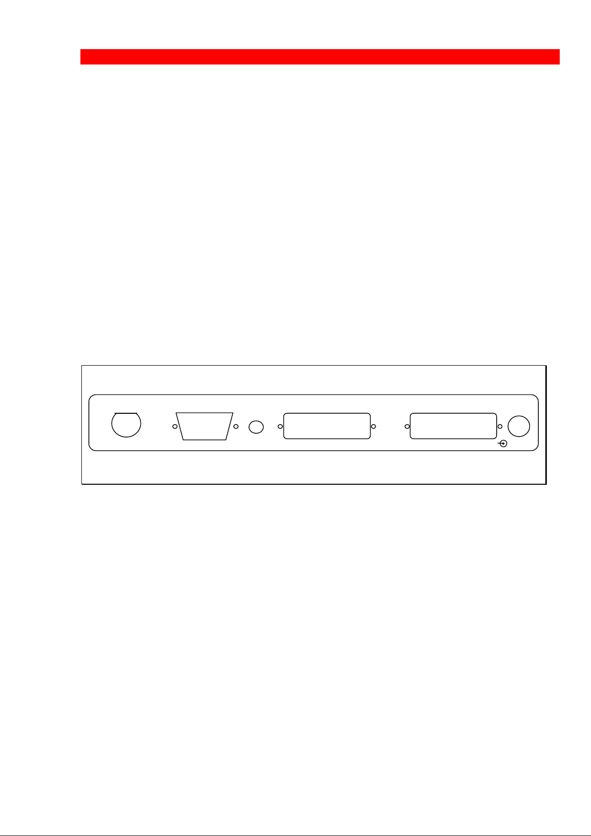
6.1. The Rear Panel
RS232
2
3
1
4
0
5
B
6
A
T
A = PCL, B = XES
Xerox FS 5250 Rear Panel
PARALLEL OUT
The parallel output port can be connected to the parallel/Centronics in put
port on the target printer (parallel out cable is supplied with the kit).
PARALLEL IN
The parallel input port can be connected to the parallel/Centronics out put on
a PC or similar source which enables it to share the printer with the host. For
this connection you need a cable ending in a 25-pole D-Sub connector
(order no. 999022 030).
PARALLEL IN PARALLEL OUTADDR
12-18 VDC.
+ --
0.7A
SERIAL IN/OUT
The serial port can be configured either as input or as output. Default
configuration is input.
- 13 -
Page 14

Connections and Installation
Xerox FS 5250, User’s Guide
The serial input port is connected to the serial output on a PC or similar
source able to share the printer with the host.
For this connection you need a cable ending in a 25-pole RS connector
(order no. 999010 030).
Y24 = 0 is also
To use the serial input, Function 24, " Data Input/Output Port Select "
must be set to zero (Centronics out, which is factory default).
used for
Centronics
output.
You must also make the following settings on your PC to match the default
settings on the box:
Function Y15: Baud rate, set to 5 = 9600
Function Y16: Number of data bits, set to 8 = 8 bits
Function Y17: Parity, set to 1 = No Parity
Function Y18: Number of Stop Bits, set to 1 = 1 Stop Bit
If this is not possible, you must change the functions 15, 16, 17 and 18 on
the box to match the PC's values.
NOTE:
Programming of functions 15, 16, 17, 18 and 24 is not possible via the
serial port. These functions have to be programmed either via the
twinax or via the parallel input port.
TWINAX CONNECTOR
Before the twinax cable is connected, be sure to turn the box power OFF.
When power is turned off, plug the automatically terminating twinax T-cable
(twin BNC cable) into the socket on the rear panel and turn the connector
ring clockwise to lock.
ADDRESS SWITCH: EMULATION & PRINTER DRIVER SELECT
You use the address switch for:
• selecting/changing emulation, setting the address and for the generating
of test printouts. Tests can also be made via the line. See the section
TEST function for details. For details on emulation see the section
"Emulation".
• selecting/changing of printer driver. You have the option of selecting
between XES and PCL.
- 14 -
Page 15

Connections and Installation
Xerox FS 5250, User’s Guide
If you wish to operate in default PCL mode, the box is ready to operate when
delivered. It is important that you do not change the position of the address switch.
Note that operation mode is outside of the B, A & T positions.
If you wish to select XES, you must follow the instructions in the below section
“Changing the Driver”.
Changing the Driver:
To change from PCL to XES driver, the rotary switch has to be in position T at
power on. Current printer driver is indicated on printout. Now turn the rotary
switch to position B (XES). New position is then indicated as “alternate printer
driver” (XES) on second printout. When correct position is obtained, turn rotary
switch away from B, A or T positions (any other position will do). Power the
converter OFF and ON again. The new driver is now active. (If you wish to
reinstall the PCL driver later on, repeat the above, setting the switch into the A
(PCL) position instead of the B (XES) position).
6.2. Emulation
If you wish to see the current emulation, you can generate a test print out by
turning the address switch to the T-position.
In Xerox FS 5250 you can select emulation in two ways. Either via the
address switch (see below) or you can do it via the line by activating FSL
function Y37 (only in PCL mode).
The following emulations are supported by the Xerox FS 5250:
IBM 3812 / 5219 / 3816
IBM 5224
IBM 5225
IBM 5256
IBM 4234
IBM 4245/6262
As default the Xerox FS 5250 will emulate IBM 3812/5219/3816.
As default the Xerox FS 5250 IPC will emulate IPDS
6.2.1 Via the Line
Selecting emulation via the line can be done in PCL only!
You can set the desired emulation in FSL function Y37.
Note that if you select emulation via function 37, you must physically write
the emulation. See the chart in the following for details.
- 15 -
Page 16
Connections and Installation
Xerox FS 5250, User’s Guide
E.g. %Y37,5224%
will select emulation 5224
An option for dual printer emulation is also available for the Xerox FS 5250
when equipped with an IPDS upgrade module. See below for a description of
dual printer emulation.
This chart provides information on the emulations which can be selected in
the n1 parameter of function Y37.
In the column "Write" is stated what you physically have to write in this
parameter.
Non-IPDS IPDS
Y37,n1 Y37,n1
Write Emulation Write Emulation
3812 *3812/5219/
3816
3812 *3812/5219/
3816
5224 5224 5224 5224
5225 5225 5225 5225
5256 5256 5256 5256
4234 4234 4234 4234
4245 4245/6262 *IPDS *IPDS
4245 4245/6262
* default value
SCS printers
6.2.2 Via the Address Switch
Emulation selected on the address switch is described in the following.
The T-cable must be disconnected at the converter before changing
emulation.
Select emulation on the address switch as follows:
1. Switch off the box
2. Turn the address switch to the "T" position.
3. Switch on power to the box.
- 16 -
Page 17
Connections and Installation
Xerox FS 5250, User’s Guide
4. When the Xerox FS 5250 is ready, it will eject a page with the follo wing
message:
"Current emulation is xxxx"
5. Set the desired emulation by turning the address switch to the position
defined in the chart in the following:
Non-IPDS IPDS
Selection Emulation Selection Emulation
*0 3812/5219/3816 0 3812/5219/3816
1 5224 1 5224
2 5225 2 5225
3 5256 3 5256
4 4234 4 4234
5 3812/5219/3816 *5 IPDS
6 4245/6262 6 4245/6262
* default value
SCS printers
6. A new message stating the current emulation will be printed after a few
seconds. Then power off the Xerox FS 5250.
7. Power on the Xerox FS 5250.
8. Turn to the "T" position again and check that the emulation has been
changed. (See the settings printout). See TEST Function.
9. Turn the switch back to the correct device address (consult your
system administrator if necessary).
10. Connect the twinax cable and power on the Xerox FS 5250 or follow
the procedure for setting the address via the switch. See the following
section.
Check whether the configuration complies with the requirements of your
installation and print jobs.
NOTE: Make sure that you have set the address switch before you switch
power on.
- 17 -
Page 18

Connections and Installation
Xerox FS 5250, User’s Guide
6.2.3 Address Setting
via the address switch
To select the desired address using the rotary address switch follow these
steps. The steps 1 through 4 are mandatory, whereas the steps 4 through 6
are optional.
1. Power off the Xerox FS 5250.
2. Disconnect the T-cable
3. Set the address switch to the desired address. The options are 0-6.
4. Power on the Xerox FS 5250. The desired address will be set at this
point of time.
5. To verify the address turn the switch to the “T” position to print the
current settings printout.
6. Turn the switch back to the desired address number.
The default configuration of the Xerox FS 5250 can be used for most
application programs and uses. You should only change the address
and the emulation if necessary. Change only the rest of the settings if
you have special requirements.
6.2.4 Dual Printer Emulation
PCL only
With IPDS support in the Xerox FS 5250, you have the option of configuring
a second emulation on a different address.
You select a second emulation via the line in function Y37 and both
parameters (n1 and n2) in Y37 must be specified.
The parameter n1 sets the printer emulation. Note that you will have to
physically write the IBM printer number of the desired emulation. For IPDS,
you must write: *IPDS. Parameter n2 specifies the device address.
- 18 -
Page 19

Connections and Installation
Xerox FS 5250, User’s Guide
NOTE:
The device address (n2) must be different from the address switch
setting or this command will only modify the primary printer emulation
without creating a secondary.
One non-IPDS and one IPDS emulation can be defined.
The secondary printer device will be deleted if you attempt to configure two
similar devices (e.g. two non-IPDS devices) or if Y37 is used without
specifying n2.
For this change to become effective, you must turn power to the converter off
for approx. 10 seconds and then back on.
Non-IPDS as primary emulation
If the primary printer emulation (set via the address switch) is set to nonIPDS, you can set the second emulation via the twinax port activating Y37.
E.g.
Primary emulation: non-IPDS (set via address switch)
Second emulation: %Y37,*IPDS,6%%X1
You have now a non-IPDS primary emulation, and a second IPDS emulation
answering on device address 6.
As an alternative setup, you can also use the Centronics port activating
function Y249, Enter Engineering Mode.
E.g.:
Primary emulation: non-IPDS (set via address switch)
Second emulation: %Y249, password%
2)
%Y37,*IPDS,5%%X1
IPDS as primary emulation
If the primary emulation is set to IPDS (set via the address switch) the only
way to set a second emulation is through the Centronics port enabling
function Y249, Enter Engineering Mode. You must still set function Y37 to
the desired emulation.
E.g.
Primary emulation: IPDS (set via address switch)
Second emulation: %Y249,password%
%Y37,3812,1%%X1
2
As the password is sensitive information, please contact point of purchase for details
- 19 -
Page 20

Connections and Installation
Xerox FS 5250, User’s Guide
With IPDS as primary emulation, you have now selected 3812 as second
emulation to answer on address 1.
NOTE:
If you wish to define 2 emulations, you are recommended to set the
primary emulation to non-IPDS.
6.3. Upgrading to IPDS
If you need to upgrade your Xerox FS 5250 with the IPC module, please follow
these instruction before proceeding with the installation.
1. Unscrew the 4 screws from the bottom of the converter.
2. Place you hands on each side of the box, bottom facing down and the rear
panel facing you. Carefully press open the top cover of the converter.
3. Place the IPC module (main component side facing up) on the PCB of the
box. Note that the connector has to be placed on top of the PCB’s
connector (to the right on the PCB).
4. Make sure the plastic supports fit in the holes of the IPC module.
5. Press the module gently into position and, while still facing the rear panel,
place the top cover precisely above the bottom cover so that all edges are
aligned. Press the top cover gently into a locked position.
6. Re-insert the screws and fasten.
7. Now proceed to the actual installation of the converter to the printer and
the system.
- 20 -
Page 21

Connections and Installation
Xerox FS 5250, User’s Guide
6.4. Connecting the Xerox FS 5250 to the Printer
CAUTION:
All connections to the Xerox FS 5250 protocol converter should be
made while the power is switched OFF to both the printer and
converter.
6.4.1 Connecting via Centronics output
Connecting the Xerox FS 5250 to the printer is done by following these
steps:
1. Check that the printer's parallel input port is available on printer.
2. Connect the cable supplied with the Xerox FS 5250 between the
printer's parallel input port and the protocol converter's PARALLEL
OUT port.
3. Power on the printer and the Xerox FS 5250.
4. Turn the address switch (on the rear panel) to the "T" position . A
settings printout is generated and the CU indicator starts flashing.
The interface can be set up in many ways. Upon delivery the interface
is set up to cover most needs and uses. Appendix B "Test Printout" is
a sample printout of settings and is but one way of setting up your
interface.
Keep the settings printout you make together with this manual for
future reference.
If the printout format does not match the test printout in Appendix B
"Test Printout", or if nothing was printed, this means that the printer
setup does not match the protocol converter setup. Contact your
systems support personnel or your point of purchase for assistance.
5. When the printout is in order, you proceed to the following section
"Connecting the Xerox FS 5250 to the System".
- 21 -
Page 22

Connections and Installation
Xerox FS 5250, User’s Guide
6.5. Connecting the Xerox FS 5250 to the System
After a successful test printout has been generated to establish that the
connection between the Xerox FS 5250 converter and the printer is working
correctly (see previous sections), you are now ready to connect the Xerox
FS 5250 to the system.
WARNING:
All connections to the Xerox FS 5250 protocol converter should be
made while the power is switched OFF.
1. Turn off the power and connect the Xerox FS 5250 to your host system
using the twinax cable, and the auto-terminating T-cable.
2. When the connection has been made, turn power ON and check that
the CU and READY indicators turn ON. When they do, you have
completed the installation procedure and are ready to operate the
protocol converter as described below.
What if the CU Indicator fails to turn on?
If the CU indicator does not turn ON, this means that there is no
communication with the control unit. You should check the follow ing:
a. The twinax cable connection from the control unit to the Xerox FS
5250.
b. The control unit (is it powered up etc.)
c. Is the control unit supported by the Xerox FS 5250 ?
(See the section "Supported Control Units" for a list of sup ported control units).
If all three (a. b. and c.) are in order, contact your systems support personnel
or your point of purchase.
- 22 -
Page 23

Connections and Installation
Xerox FS 5250, User’s Guide
6.5.1 TEST Function
The test printout pages can be generated in two ways - via the address switch
or via the line by activating the T function . For details on the T function, please
see the section "Quick Reference Guide of the Supported FSL Functions".
Test via the address switch
1. Turn the address switch to the "T" position. A settings printout will be
generated (test 4).
2. Turn the switch away from the T- position.
3. When the CU indicator flashes, turn the switch back to the T-position.
4. The printer will now enter Online HEX Dump mode and print all data
received in on-line HEX dump format ( test 1).
5. Hex dump mode is terminated by turning the address switch away from
the T-position and then back again.
Keep the settings printout together with this manual for future
reference.
Finally, a settings printout can also be generated at power on by activating
function Y120. See the section "Quick Reference Guide of the Supported
FSL Functions" for details.
NOTE:
You are recommended when installing for the first time to carry out
Test 4, Settings Printout, to check whether the printer is set to the
correct language. if the language is incorrect, contact your systems
support or your point of purchase.
- 23 -
Page 24

Connections and Installation
Xerox FS 5250, User’s Guide
6.5.2 Timeout
The Xerox FS 5250 enables printer sharing between the system and a PC.
For this purpose it is possible to specify a timeout period.
If the printer is receiving input on the parallel port, for example, and there is
a break in the transmission of data, the other input ports will not be polled for
the period specified.
The factory default timeout is 20 seconds. The timeout may be changed
to suit your requirements. This is done by sending a new setup to the Xerox
FS 5250 input port where you want it to take effect.
When specifying the timeout it is also possible to specify a user string. A
user string may be used for changing from one symbol set (e.g. Roman 8) to
another (e.g. IBM-PC8), for example.
NOTE:
Settings on the twinax input port are automatically re-established after
another input port has been using the printer.
On the parallel and RS input port, you have to program the required
setup yourself.
For more detailed information on the commands required, see the section
"Port Share Option".
- 24 -
Page 25
Operation
Xerox FS 5250, User’s Guide
7. Operation of the Xerox FS 5250
The Xerox FS 5250 top panel has been designed to register the operation of
the box via the four following indicator LEDs :
• CU (contact to control unit)
• PAR (parallel input)
• SER (serial input)
• READY (printer)
7.1. Top Panel of the Xerox FS 5250
7.1.1 CU
The CU indicator has 3 states which signal the following:
State Indication
ON Contact with the control unit.
OFF No contact of the control unit, or the contact
has been broken for more than 1 minute
7.1.2 PAR (Parallel input)
The indicator LED has 2 states:
State Indication
ON
OFF
Indicates that the box is processing data from the
Centronics parallel port
Indicates that the box is idle or processing data from
the twinax/RS232 inputs
- 25 -
Page 26
Operation
Xerox FS 5250, User’s Guide
7.1.3 SER (Serial input/output)
The indicator LED has 3 states
State Indication
ON
Indicates that the box is processing data from the RS232 Serial input
BLINKING
Indicates that the box has defined the RS-232 as
output for the box.
OFF
Indicates that the box is idle or is processing data from
the twinax/Centronics inputs.
7.1.4 READY (Printer Ready)
The indicator LED has 2 states:
State Indication
ON
Indicates that the connected printer is ready; i.e. that
printer's "Select" condition is active and the "PE"
signal is inactive. If the connected printer is an RS 232
printer, the ready validation is done by the "DTR"
signal.
BLINKING The printer is not ready and print may be pending
in the buffer.
OFF Indicates that the connected printer is not ready for
data input.
- 26 -
Page 27

Function Selection via the Line
Xerox FS 5250, User’s Guide
8. Function Selection via the Line
NOTE:
This section is a brief description of how to set up the interface from
the line using FSL Functions.
The guidelines in this section are very basic and limit themselves to what
you need to know. For further details on the supported FSL functions, you
are referred to the Programmers Guide, doc. no. D62081. The Programmer's
Guide will contain a complete list of the supported functions with description,
notes and examples.
FSL functions are special commands in the data stream which set up the
Xerox FS 5250 and consequently the printer to function in a specific way.
Some FSL Functions differ according to whether you are in PCL or in XES
mode.
Appendix A of this manual contains a Quick Reference Guide to the FSL
functions. This list only comprises the syntax and parameters of the
supported FSL functions. The reference guide will contain remarks on
deviations as to XES or PCL
8.1. Syntax of an FSL Function
The special sequence that the interface will interpret as an FSL Function is
shown below:
%Y<function number>,<parameters>%
where % is the defined escape character. See the description below on the
Escape Character.
- 27 -
Page 28

Function Selection via the Line
Xerox FS 5250, User’s Guide
8.2. The Escape Character
The Xerox FS 5250 is managed by special es cape sequences sent to the
printer via the line. Escape se quences are command sequences preceded
by a defined escape character. When an escape character appears in the
data stream, the printer will inter pret the characters following as a command
string and not as characters to be printed.
When you have defined an escape character, you can:
* Configure the interface according to your needs.
* Send all XES/ PCL commands in HEX code (00 to FF) to the interface
* Download settings to the Xerox FS 5250
* Send commands to the Xerox FS 5250
(save the temporary memory area in the permanent memory area,
etc.)
When a character has been defined as an escape character, you will not be
able to use it as a normal character and print it. However, you do not need to
have an escape character defined perma nently. When it has served its
purpose, it can be removed.
The escape character described in this manual is different from the printer
escape character and the IBM escape character and cannot be used for
sending native printer commands, UDKs or system commands.
This chapter explains how to configure and manage the Xerox FS 5250 by
the use of Escape Sequences. It also explains how to save the interface
settings.
NOTE:
The factory defaults of the printer will normally suffice for most uses,
and in most cases your software will control the facilities described
below. This means that you will be able to connect the printer to your
host system and start printing without changing the printer settings.
The settings should only be changed, if your software or hardware have
special requirements.
- 28 -
Page 29

Function Selection via the Line
Xerox FS 5250, User’s Guide
8.3. Defining a Temporary Escape Character
No escape character is defined when you receive the printer. If you wish to
change the settings of the printer from the host system, you will have to
define the escape character. See below how to define "%" as the tem porary
escape character.
NOTE:
The characters "," ";" and ":" must never be used as escape characters,
as they are used as separators in escape sequences and will be ignored by the printer.
The same applies to 0-9, A-F, a-f and K,S,T,X,Y,Z, simple quote ('), &
and ?. These must not be used.
CAUTION!
Avoid using your national characters as ESC characters.
The following EBCDIC HEX codes have been defined as national
language characters and must not be used as ESC characters
4A 4C 4F 5A 5B 5F 6A 79 7B 7C 7F A1 C0 D0 E0
&&??%
Defining a temporary escape character.
The five characters shown should be sent to the printer from the host
system. The escape character is not defined permanently. When the
converter is turned off, it will be lost. See "Defining a Permanent Escape
Character" for information on the definition of a permanent escape character.
8.4. Removing Temporary Escape Character
If you wish to remove the temporary escape character so that it may be used
as a printable character, you can define it as a blank as shown below.
&&??<blank>
Removing the temporary escape character.
- 29 -
Page 30
Function Selection via the Line
Xerox FS 5250, User’s Guide
8.5. Defining a Permanent Escape Character
The paragraph "Defining a Temporary Escape Char acter", only described
the saving of the escape character in the temporary memory .
If you wish to define and save a permanent escape character in the printer,
you will have to use Function 48, Select Perma nent Escape Character, and
immediately save the settings in the permanent memory . See the description
of Y48 in either XES or PCL.
NOTE:
If the character used in Function 48, Select Permanent Escape
Character, is different from the one specified as temporary escape
character, the latest specified character will take precedence immediately.
An example of the commands defining the permanent escape charac ter is
shown below.
PCL XES
&&??% &&??%
%Y48,08% %Y48,4C%
>X1 >X1
Syntaxes of the command strings defining the permanent escape character to be 08
(the character ">") instead of the temporary escape character "%".
8.6. Removing Permanent Escape Character
If you wish to remove the permanent escape character , you will have to
follow the procedure below:
1. Set Function 48, Select Permanent Escape Character, to "00" (No
escape character).
2. Define a new temporary escape character as described in "Defining a
Temporary Escape Character".
3. Save the settings using the command "<ESC> X1".
Examples of these commands are shown below.
- 30 -
Page 31

Function Selection via the Line
Xerox FS 5250, User’s Guide
>Y48,00>
&&??%
%X1
Syntax of the command strings to remove the permanent escape character (">"). "%"
is defined as temporary escape character.
- 31 -
Page 32

Function Selection via the Line
Xerox FS 5250, User’s Guide
8.7. Commands for Storing and Restoring
Settings
The commands listed below permit you to read and save the settings in the
NVRAM area. You may also read the factory defaults.
Please observe that when one of the commands below are used, the
temporary escape character, if any, will be removed.
Command Description Example
%X1
%X3
%X4
This command is needed
to save settings in the
interface memory.
Without the %X1, change
of settings will be lost at
power off.
Read and activate factory
default settings.
Use this command if you
have changed many
settings and wish to start
all over again.
Read and activate the
permanent settings.
Use this command if you
have changed a couple of
settings temporarily for a
specific purpose. When
you have used the
temporary settings, you
can erase them again by
sending the X4 command.
You will then be back in
the settings programmed
into the interface.
You send the
command as follows:
&&??% %X1
You send the
command as follows:
&&??% %X3
You send the
command as follows:
&&??% %X4
- 32 -
Page 33

Function Selection via the Line
Xerox FS 5250, User’s Guide
8.8. Pass-Through Mode
Pass-through transparency mode is implemented to offer an extended
support for applications that require greater flexibility than offered by the
double escape transparency mode.
PCL only
Pass-through mode can be defined in 2 ways:
1. pass-through mode where 1 byte of hex data is sent to the printer
(e.g. %1B)
2. pass-through mode where more bytes of hex data is sent to the printer
(e.g. %%1B%)
- 33 -
Page 34

Function Selection via the Line
Xerox FS 5250, User’s Guide
8.8.1 Pass-through mode - XES
1. Syntax of pass-through of 1 byte of hex data to the printer:
<ESC>hex pair
E.g. %1B
2. Pass-through of more bytes of hex data to the printer can be done in 2
ways.
Either way, you must follow these rules:
Hexadecimal data must either in hex pairs (00-FF).
Spaces, commas and IBM control codes are ignored when in hex
transparent mode. Commas and spaces can be used to make the
hexadecimal data more readable.
• Pass-through of more bytes of hex data by using the escape
character:
<ESC><ESC>hex data<ESC>
• Pass-through of more bytes of hex data by using the lead-in/lead-out
strings:
The lead-in/lead-out strings have to be defined in function Y48:
<ESC>Y48,<n1>[;<n2>;<n3>]<ESC>
where:
n1 is the defined escape character
n2 is the lead-in (start) hex transparent string
n3 is the lead-out (stop) hex transparent string
An example of a supported syntax :
%%Hex data%%
The difference between the syntax and the normal syntax is that this
sequence in the example above both starts and ends with two escape
characters. Any combination of up to five characters can be used for
both lead-in and lead-out strings.
To make the Xerox FS 5250 support this syntax use the following
setup:
&&??##Y48,00;'%%';'%%'#
- 34 -
Page 35

Function Selection via the Line
Xerox FS 5250, User’s Guide
NOTE:
When this pass-through option (with the lead-in/lead-out sequences) is
used, it should be noted that apostrophe notation cannot apply. Only
EBCDIC characters 0-9, A-F, a-f and spaces are accepted after a lead-in
sequence. Control codes are suppressed. Other characters will
terminate pass-through mode.
3. Filtered pass-through
To enter filter mode in XES, a lead-in and a lead-out string defined in
function Y48 must be used:
Filter mode:
<start string>-<stop string>
This setting makes any text and IBM commands other than hex
transparent data to be suppressed.
Normal mode
<start string>+<stop string>
This settings enables normal handling of text and IBM
commands outside hex transparent data.
For details refer to the programmers guide, doc. D62081.
8.9. Transparency Mode Limitations
XES
The supported FSL functions of Xerox FS 5250 are accepted in all modes,
but they have limited influence on the formatting in the various modes (Y70
and Y36).
For details on the FSL functions' influence on the formatting, you are
referred to the Programmer's Guide, doc. no. D62081.
- 35 -
Page 36

IPDS Programming
Xerox FS 5250, User’s Guide
9. idaSetup - IPDS Programming
NOTE:
This chapter only applies to the converter when mounted with an IPC
module.
idaSetup is a program developed with the purpose of setting up the wide range
of IPC protocol converters via a PC share port or from a host.
For details on how to configure the IPDS parameters for the Xerox FS
5250 IPC using the program idaSetup, see the separate documentation for
this, “IPDS, Programmer’s Guide”, doc. no. D60253. The manual is
available as an electronic document.
- 36 -
Page 37

Programming - Non-IPDS
Xerox FS 5250, User’s Guide
10. Programming the Xerox FS 5250
- Non-IPDS
The Xerox FS 5250 works using a large number of internal Setup Functions
(FSL Functions)3.
FSL setup functions can be sent either from your IBM system or from a PC.
When the protocol converter has been installed and connected to a printer,
you may have to consider the use of these setup options.
The factory default setup will meet the demands of most host systems and
users, and special programming is therefore normally not required.
If, however, special circumstances require you to make changes to the pro-
gramming of the box, appendix A: ”Quick Reference Guide of the Supported
FSL Functions” lists all the functions supported in XES and PCL mode. This
list only describes the functions by their syntax and parameters, though. In
the Programmer's Guide, doc. no. D62081, you will find an extensive
description of the FSL Functions with notes, comments and examples.
3.
FSL = Function Selection via the Line
- 37 -
Page 38

Selected FSL Functions
Xerox FS 5250, User’s Guide
11. Selected FSL Functions
In this chapter, only the most basic functions are described, such as paper
size, paper tray and font selection.
Appendix A: Quick Reference Guide to the FSL functions lists all the
supported FSL functions with syntax and parameter
For detailed information on the entire range of the supported FSL functions
with the Xerox FS 5250, you are referred to the Programmer's Guide, doc.
no. D62081.
11.1. Paper Size
Function Y12: Paper Size
NOTE:
In XES, function Y62 must be programmed for this function to become
effective.
Almost any printer will provide you with the facility of selecting various paper
sizes, but there are different ways of changing paper size in the printer. In
some cases you can use the application software to change it, you can send
printer commands directly to the printer, or you can send commands to the
interface from the system. This chapter only describes the procedure for
changing paper through the interface.
11.1.1 Trays
If your printer has several paper trays with different paper sizes, remember
to select the corresponding paper tray, when you change the paper size.
If your printer only has one paper tray with one paper size, you can perhaps
buy additional paper trays for other paper sizes and change trays manually.
11.1.2 Changing paper size
You can change paper size by sending commands to the interface from the
system.
The FSL function is primarily designed to inform the interface about the
installed paper sizes during installation.
- 38 -
Page 39

Selected FSL Functions
Xerox FS 5250, User’s Guide
The paper size command has two parameters4. The first parameter (n1)
establishes the paper size to be used, the second (n2) tells the interface in
which tray the paper type is. If you use the n2 option together with an n1
option, you can connect one paper size to a specific paper tray. You send
the command as follows:
&&??% %Y12,<n1>[,n2]% &&??<space>
The command &&??% selects the character "%" as the escape character .
The escape character is a signal to the interface that the data stream
following is a command stream. The last command in the above line (&&??
<space>) erases the temporary escape character again.
The %Y12 command tells the printer which paper size to use. You have the
following options for the n1 parameter:
Value Paper Size XES PCL
1 A4 x x
2 Legal x x
3 Letter x x
4 Executive x x
5 Letter (Monarch) x x
6 Business x x
7 International DL x x
8 International C5 x x
10 A3 x x
11 US Ledger x x
99 Use system SPPS or
x
SHF/SVS values
You do not have to enter an n2 value. If you do not do so, the n1 value will
be used for all trays. If you wish the n1 value only to be used for a specific
tray, you must enter one of the following values:
Value Paper Tray
1 Tractor
2 Tray 1
3 Tray 2
4 Manual Feed
5 Envelope Feed
6 Tray 3
7 Tray 4
4
The parts of the command that contains a specific instruction to the interface is a
parameter. The command 3 = Letter size paper is a parameter.
- 39 -
Page 40

Selected FSL Functions
Xerox FS 5250, User’s Guide
11.1.3 Saving the command
When you have tied a paper size to a specific tray, you can tell the interface
to remember these commands. In this way you only need to change paper
tray in the future. This will automatically mean a change of paper size. You
do this by adding the %X1 to the command illustrated above:
NOTE:
This command also erases the escape character.
11.1.4 Changing paper size example
&&??% %Y12,3,3% %Y12,1,2% %X1
This will link letter-size paper to the tray 2 (Y12,3,3) and A4 paper to tray 1
(Y12,1,2). The settings will be saved permanently, and the escape character
will be erased (X1).
11.1.5 Other commands
Other commands that can be used in connection with the paper size
command, are:
Y5, Number of Lines per Page
Y10, Page Format
Y11, Paper Tray Selection
Y96, Font Change
Y98, Automatic Page Orientation
- 40 -
Page 41

Selected FSL Functions
Xerox FS 5250, User’s Guide
11.2. Paper Trays
Function 11: Paper Path
NOTE:
In XES, function Y62 must be programmed for this function to become
effective.
This chapter describes how you select paper trays on your printer. This
facility has many different uses.
If your printer has more than one paper tray, you can store different sizes
and types of paper in different trays. This could be company paper in one
tray, blank paper in another, and coloured paper in yet another tray.
11.2.1 Basic printer set-up
The set-up of the printer front panel will not matter in this connection. The
commands sent to the interface will overwrite front panel settings.
NOTE:
XES only. This applies only when function Y36 is set to 0.
11.2.2 Changing paper trays
The tray command only has one parameter. If 3812/5219 emulation is used
then paper tray can be selected with system commands.
Using FSL commands, you send a tray selection command as follows:
&&??% %Y11,<n1>%
The command &&??% selects the character "%" as the escape character.
The escape character is a signal to the interface that the data stream
following is a command stream.
Saving the command
When you have changed the paper tray, you can tell the interface to
remember the correct settings. You do this by adding the %X1 command to
the command illustrated above.
Example:
&&??% %Y11,3% %X1
- 41 -
Page 42

Selected FSL Functions
Xerox FS 5250, User’s Guide
This will make the printer use the tray 2 (Y11,3), save the settings
permanently, and erase the escape character (X1).
NOTE:
This command also erases the escape character.
11.2.3 Other commands
Other commands that can be used in connection with paper tray selection, are:
Y10, Page Format
Y12, Paper Size
Y89, Margin Compensation
Y98, Automatic Page Orientation
11.3. Page Format
Function Y10: Page Format
Many types of printing from IBM software have been made for specific paper
sizes that are larger or wider than A4 paper or letter-size paper. Other types
of software expect a specific printer to be able to scale printing in order to fit
the installed paper. This will give you problems, when you use other printers
as system printers. To overcome this problem, you can select different page
formats coded into the interface via function Y10. When you do so, the
interface will scale the printing to fit the paper size you use.
Syntax of the command: %Y10,<n1>[,n2]%
11.3.1 Formats
You can select between the following formats:
Value (n1) Format Characteristics
0 Portrait No scaling
1 Landscape No scaling
2 Computer Output
Reduction
(COR)
82 COR, regardless of PPM
Print Quality
Scaled vertically to
70%
as on IBM 3812
Scaled vertically to
70% as on IBM 3812
- 42 -
Page 43

Selected FSL Functions
Xerox FS 5250, User’s Guide
Note: The option 2, COR, is printed in Landscape orientation with
reduced vertical and horizontal spacing. Vertical spacing is 70 %
of normal, thus reducing as follows:
10 pitch fonts will be converted to 13 pitch
12 pitch fonts will be converted to 15 pitch
15 pitch fonts will be converted to 20 pitch
17 pitch fonts will be converted to 27 pitch
11.3.2 Changing Page Format
The page format command has two parameters. You send the command as
follows:
&&??% %Y10,<n1>[,n2]% &&??<space>
The command &&??% selects the character "%" as the escape character.
The escape character is a signal to the interface that the data stream
following is a command stream. The n1 is described at the previous page.
The last command in the above line (&&?? <space>) erases the escape
character again.
You do not have to enter an n2 value. If no parameter is entered for n2, the
n1 value will be used for all trays. If you wish the n1 value to be used for a
specific tray only, you must enter one of the following values:
Value (n2) Tray
1 Tractor
2 Tray 1
3 Tray 2
4 Manual feed
5 Envelope feed
6 Tray 3
7 Tray 4
Saving the command
When you have changed the paper tray, you can tell the interface to
remember the command. You do this by adding the %X1 to the command
illustrated above.
NOTE:
This command also erases the escape character.
- 43 -
Page 44

Selected FSL Functions
Xerox FS 5250, User’s Guide
11.3.3 Changing page format example
&&??% %Y10,2,3% %X1
This will set the default value for page format to COR for tray 2 (Y10,2,3),
will save the settings permanently and erase the escape character (X1).
11.3.4 Other commands
Other commands that can be used in connection with page format selection,
are:
Y11, Select paper tray
Y88, Physical Margins
Y98, Automatic Page Orientation
- 44 -
Page 45

Selected FSL Functions
Xerox FS 5250, User’s Guide
11.4. Automatic Page Orientation
Function Y98: Automatic Page Orientation
Selecting this function will activate and deactivate the automatic page
orientation for the trays.
Automatic Page Orientation (i.e. APO) works in connection with FSL Y98.
The factory default value is Y98,1 (i.e. APO = disabled). When APO is
disabled, page orientation is controlled by the values in FSL Y10.
Y98 Syntax
%Y98,<n1>,[[ n2]]%
where:
n1 = 0: Enable APO
n1 = 1: Disable APO
n2 = 1: Tractor
n2 = 2: Tray 1
n2 = 3: Tray 2
n2 = 4: Manual feeder
n2 = 5: Envelope feeder
n2 = 6: Tray 3
n2 = 7: Optional feeder
Factory default for n2 is all trays.
Example:
%Y98, 0,3%
will activate Automatic Page Orientation for tray 2.
- 45 -
Page 46

Selected FSL Functions
Xerox FS 5250, User’s Guide
11.4.1 Automatic Page Orientation Chart
Below follows a navigation chart for automatic page orientation. The section
following will describe how automatic page orientation operates.
Automatic Page Orientation
- 46 -
Page 47

Selected FSL Functions
Xerox FS 5250, User’s Guide
Explanation to the chart on Automatic Page Orientation
Initially, the system will make a request as to the determination of the page
orientation. Indicated in the chart as "STO Used?"
The system has 4 different orientation options:
- Portrait
- Landscape
- Computer Output Reduction (COR)
- Device dependent (i.e. the Xerox FS 5250)
If the system has set page orientation to "Device Dependent", the Xerox FS
5250 will determine the page orientation. In the chart indicated as
"STO=FFFFh?" set to YES.
NOTE:
If the system commands specifies a specific orientation, it will override
the command sequences of the Xerox FS 5250. In the chart indicted as
"USE STO COMMAND".
Y98 Enabled (factory default)
When the Xerox FS 5250 determines the orientation and function Y98 is
enabled, the logical page size is compared to the physical page as defined
in Y12, value n3. In the chart indicated as "Page Size valid?".
If the logical page fits within the frame of the physical page as defined in
Y12,3 (and with Y98 enabled), the page orientation is determined by the
relation between the height and the width of the logical page.
If the logical page does not fit within the frame of the physical page, the page
orientation will be set to default value as specified in function 10. See the
chart.
The orientation may be in landscape, portrait or in COR. If you select COR
and the system's print quality is not set to draft, then printing will be made in
portrait.
- 47 -
Page 48

Selected FSL Functions
Xerox FS 5250, User’s Guide
If there is no STO command, no valid page size specified for Function Y98:
Automatic Page Orientation, and the selected tray is set to COR, portrait
orientation can be selected by setting the following parameters:
System /38 CL: PRTQLTY (*STD) or (*NLQ)
PAGRITT
System /36 OCL: TEXT -YES
ROTATE-0
Y98 Disabled
If function Y98 is disabled or if the logical page is wider and longer than the
physical page (i.e. page not valid), then function Y10 will determine the page
orientation. The interface will then use the default orientation as specified in
Y10. The orientation may be in landscape, portrait or in COR. If you select
COR and the system's print quality is not set to draft, then printing will be
made in portrait.
11.5. Fonts
This section will provide the user with details on font selection and definition
in PCL and XES mode.
11.5.1 Selecting Fonts - PCL
NOTE:
The procedures in this chapter can only be used, if you have selected
the PCL option on the interface.
The Xerox FS 5250 emulates the IBM 5219 or 3812 printers. The fonts of
these printers are different from the fonts5 of a Xerox printer. You can install
more fonts either as soft fonts or as font cassettes in the printer.
Many software programs will provide you with the facility of changing fonts.
But if your software does not have this facility, you can still change fonts in a
document by sending FSL commands to the interface.
What to consider
When you send a font change command to the interface, you must
remember the following:
5
See the basic printer manuals for an explanation of fonts.
- 48 -
Page 49

Selected FSL Functions
Xerox FS 5250, User’s Guide
1. The system and system software will not know that you have changed
font. This means that data will be transmitted to the printer as before
the font change. This will give you format and position problems.
Changing font
The font change command has one parameter, the GFID value . You can
change the contents of this value, if you wish to use a font that is not in the
list. See the paragraph below on how to define a font. You send the font
change command as follows:
&&??% %Y96,<n1>% &&??<space>
NOTE: This function cannot be saved in the permanent memory.
The command &&??% selects the character "%" as the escape character.
The escape character is a signal to the interface that the data stream
following is a command stream. The last command in the above line (&&??
<space>) erases the escape character again.
As mentioned above, the n1 value is the IBM value Global Font ID (GFID).
These values have been coded into the interface. When you enter a GFID
value, you automatically activate a font with a number of characteristics. See
the table below for the GFID values you can use and their characteristics.
- 49 -
Page 50

Selected FSL Functions
Xerox FS 5250, User’s Guide
11.5.2 Default GFID Table
The factory default GFID Table below lists all the predefined fonts which are
supplied with the interface GFIDs (GFIDs 1 - 399)6.
Fonts with GFIDs above 400 (i.e. scaleable fonts) are described in the
section "Scaleable Fonts" below.
For further details on defining fonts, please see the chapter "FSL Quick
Reference Guide, the functions Y91 and Y96.
If more details on these FSL functions are required, you are referred to the
Programmer's Guide (D62081).
In the following Default GFID Table, the Attribute, Symbol Set and Translate
Table figures will refer to the following:
ATTRIBUTE
0 = No attributes
1 = Bold
2 = Italic
3 = Bold and italic
4 = Proportional
5 = Proportional bold
6 = Proportional italic
7 = Proportional bold and italic
SYMBOL SET and TRANSLATE
TABLE
1 = Roman 8
2 = IBM PC-8
3 = ECMA Latin 1
4 = Roman 8
5 = US ASCII
6 = OCR A
7 = OCR B
8 = PC 850
6
If, for reasons of backward compatibility, you wish to reestablish the fonts > 400 in the
default GFID table, please contact you i-data supplier.
- 50 -
Page 51

Selected FSL Functions
Xerox FS 5250, User’s Guide
In the table below, an asterisk (*) after the GFID number denotes a
simulated IBM GFID.
GFID Font Type-
face
3* OCR B 0 0 7 12 7
11* Courier 3 0 1 12 0
12* Prestige 8 0 1 10 1
18* Courier 3 2 1 12 1
19* OCR A 0 0 6 12 6
38* Presentation 11 1 5 14 5
39* Letter Gothic 6 1 1 14 1
40* Letter Gothic 6 0 1 14 1
46* Courier 3 1 1 12 1
51 Courier 3 0 5 12 5
52 Courier 3 1 5 12 5
53 Courier 3 2 5 12 5
60 Letter Gothic 6 0 5 14 5
66* Letter Gothic 6 0 1 12 1
68* Letter Gothic 6 2 1 12 1
69* Letter Gothic 6 1 1 12 1
80 Prestige 8 0 1 10 0
85 Courier 3 0 1 12 1
86* Prestige 8 0 1 10 1
87* Letter Gothic 6 0 1 12 1
91* Letter Gothic Italic 6 2 1 12 1
95* Courier Italic 3 2 1 10 1
109* Letter Gothic Italic 6 2 1 12 1
110* Letter Gothic 6 1 1 12 1
111* Prestige 8 1 1 10 1
112* Prestige 8 2 1 10 1
115 Courier 3 1 1 10 1
116 Courier 3 2 1 10 1
117 Prestige 8 0 5 10 5
118 Prestige 8 0 5 10 5
119 Prestige 8 2 5 10 5
204* Letter Gothic 6 0 5 12 5
221* Prestige 8 0 1 7 1
223* Courier 3 0 1 8 1
230* Letter Gothic 6 0 1 9 1
252* Line Printer 0 0 1 8.5 1
253 Line Printer 0 0 1 8.5 0
255 Letter Gothic 6 0 1 9.5 1
256 Prestige 8 0 5 7 5
Default GFID Table for GFIDs 1 - 399
Attribute
Symbol
Set
Point
Size
Translate
Table
- 51 -
Page 52

Selected FSL Functions
Xerox FS 5250, User’s Guide
11.5.3 Scaleable Fonts
NOTE:
Only applies to printers running PCL Level 5.
The Xerox FS 5250 allows GFID access to all the scaleable fonts found in
the printer. These GFIDs are in the range 400 - 65535.
Typeface, typeface attributes and point size have been linked together using
the system described below.
GFID Number = XXXYY
where XXX = point size
YY = typeface + attribute
Possible typeface values are:
Typeface ID PCL No. Name of Typeface
0 5 Times Roman
4 4116 Coronet
10 4 Helvetica / Swiss
14 36 Helvetica Compressed
20 23 Century Schoolbook
24 4297 Mangold
30 17 Humanist / CG Optima
34 4168 Antique Olive
40 31 ICT Avantgarde
44 4197 Garamond Antique
50 16901 Times New
54 16602 Arial
60 52 Univers
- 52 -
Page 53

Selected FSL Functions
Xerox FS 5250, User’s Guide
Possible attribute values are:
Style Strokeweight
0 Medium upright
1 Bold upright
2 Medium italic
3 Bold italic
%Y96,4815%
This is 48 point, Helvetica Compressed, bold upright
%Y96,1301%
This is 13 point, Times Roman, bold upright
Font examples
Other relationships between IBM GFID and printer typefaces/fonts can be
programmed using Function 91 or 97 (See Programmer's Guide for more
details on Function 97). GFIDs may be selected with the normal procedure
or using Function 96.
11.5.4 Defining Fonts - PCL
NOTE:
The procedures in this chapter can only be used, if you have selected
the PCL option on the interface (see the chapter on Installation).
The font definition command has 6 parameters. You can find a description of
the contents of the 6 parameters below. The last parameter (translate table)
is optional, and you do not need to enter it.
All printers have a number of internal fonts . The more sophisticated the
printer is, the more fonts it has. But in addition to these, you can acquire
more fonts either as soft fonts that you download to the printer, or as font
cassettes or font cards that you push into a slot on the pr inter. Not all
existing fonts are in the GFID list in the previous chapter. But you can define
a GFID number for them on your own. In this chapter you will find an
explanation of how to do this.
- 53 -
Page 54

Selected FSL Functions
Xerox FS 5250, User’s Guide
The parameters of the font definition command are as follows:
n1 is the GFID number
n2 is the typeface
n3 is the attribute
n4 is the symbol set
n5 is the point size
n6 is the translate table (optional)
What you need to know
When you define the GFID for a font, you will need the following information
before you start:
• GFID number
• symbol set
• attributes
•• point size
• translate table
• typeface
Which GFID number will you use?
You can either use one of the existing numbers covering a font that resembles the font you wish to define, or you can use a number that has not
been used yet.
The symbol set of the font
You can select between the following symbol sets :
Value Symbol set
1 Roman 8
2 IBM PC-8
3 ECMA 94
5 US ASCII
6 OCR A
7 OCR B
8 PC 850
- 54 -
Page 55

Selected FSL Functions
This is Courier, fixed
spacing, no attribute
This is Courier, fixed
spacing, bold
This is Courier, fixed
spacing, italic
This is Courier, fixed
spacing,bold, italic
Xerox FS 5250, User’s Guide
The attributes of the font
You can select between the following attributes (the examples are all 12
point fonts):
Value Attribute Example
0 No attribute
1 Bold
2 Italic
3 Bold and italic
4 Proportional spacing This is Helvetica,
proportional spacing
5 Proportional spacing,
bold
6 Proportional spacing,
italic
7 Proportional spacing,
bold and italic
This is Helvetica,
proportional spacing, bold
This is Helvetica, proportional
spacing, italic
This is Helvetica,
proportional spacing, bold,
italic
The point size of the font
You can here state the size of the font (s). The interface cannot calculate
point size with decimals. This means that when you enter a value with
decimals, the interface will round off the decimals, e.g. 7.4 will become 7.
Which translate table will you use?
You can select the following translate table s:
Value Translate table
0 All resident
1 Roman 8
2 IBM PC-8
3 ECMA 94
5 US ASCII
6 OCR A
7 OCR B
8 PC 850
- 55 -
Page 56

Selected FSL Functions
Xerox FS 5250, User’s Guide
NOTE:
The symbol set and the translate table should be set to the same value,
e.g. both to 3 ECMA 94. If you select value 3 as symbol set and 1 as
translate table, you will probably have problems with several
characters.
- 56 -
Page 57

Selected FSL Functions
Xerox FS 5250, User’s Guide
The typeface of the font
Value Typeface
0 Line Printer
1 Pica
2 Elite
3 Courier
4 Helvetica
5 Times Roman
6 Letter Gothic
7 Script
8 Prestige
9 Caslon
10 Orator
11 Presentations
12 Helv Condensed
13 Serifa
14 Futura
15 Palatino
16 ITC Souvenir
17 Optima
18 ITC Garamond
19 Cooper Black
20 Ribbon (Coronet)
21 Broadway
22 Bauer Bodoni Black
Cond.
23 Century Schoolbook
24 University Roman
25 Helv Outline
26 Futura Condensed
27 ITC Korinna
28 Naskh (generic
Arabic)
29 Cloister Black
30 ITC Galliard
31 ITC Avant Garde
Gothic
32 Brush
33 Blippo
34 Hobo
35 Windsor
ValueTypeface
36 Helv Compressed
37 Helv Extra Comp.
38 Peignot
39 Baskerville
40 ITC Garamond
Cond.
41 Trade Gothic
42 Goudy Old Style
43 ITC Zapf Chancery
44 Clarendon
45 ITC Zapf Dingbat
46 Cooper
47 ITC Bookman
48 Stick
49 HP-GL Drafting
50 HP-GL Spline
51 Gill Sans
52 Univers
53 Bodoni
54 Rockwell
55 Melior
56 ITC Tiffany
57 ITC Clearface
58 Amelia
59 Park Avenue
60 Handel Gothic
61 Dom Casual
62 ITC Benguiat
63 ITC Cheltenham
64 Century Expanded
65 Franklin Gothic
66 Franklin Gothic
Expressed
67 Franklin Gothic Ext.
Cond.
68 Plantin
69 Trump Mediaeval
70 Futura Black
- 57 -
Page 58

Selected FSL Functions
Xerox FS 5250, User’s Guide
Font definition example
&&??% %Y91,521,6,5,1,18,1% %X1
This will define GFID 512 as a Helvetica, proportional bold, Roman 8 symbol
set, point size 18, and translate table 1 (Roman 8). It will then save settings
permanently and erase the escape character (X1).
Other commands
Other commands that can be used in connection with font definition, are:
Y3, CPI
Y92, Font Point
Y93, Font Attribute
Y94, Font Typeface
Y96, Font Change
Y97, User Defined GFID/Font Selection
11.5.5 Selecting Fonts - XES
NOTE:
The procedures in this chapter can only be used, if you have selected
the XES option on the interface (see the chapter on installation
requirements).
You can have many laser printers connect to the Xerox FS 5250, have a
large number of internal fonts7 and install more fonts either as soft fonts or
as font cassettes. This chapter describes how you can use these fonts.
Many software programs will provide you with the facility of changing fonts.
But if your software does not have this facility, you can still change fonts in a
document by sending commands to the interface.
What to consider
When you send a font change command to the interface, you must
remember the following:
1. The system and system software will not know that you have changed
font. This means that data will be transmitted to the printer as before
the font change. This may give you format problems.
7
See the basic printer manuals for an explanation of fonts.
- 58 -
Page 59

Selected FSL Functions
Xerox FS 5250, User’s Guide
2. If you only send a font change without also changing Lines Per Inch
and/or Characters Per Inch, you could have format problems.
Changing font
The font change command has one parameter, the GFID value . You can
change the contents of this parameter, if you wish to use a font that is not in
the list. See the next chapter on how to define a font. You send the font
change command as follows:
&&??% %Y96,<n1>% &&??<space>
The command &&??% selects the character "%" as the escape character.
The escape character is a signal to the interface that the data stream
following is a command stream. The last command in the above line (&&??
<space>) erases the temporary escape character again.
NOTE:
This function cannot be saved in the permanent memory.
Changing font example
&&??% %Y96,41% &&??
This will select the font defined as number GFID 41. It will also erase the
escape character.
Other commands
The other command that can be used in connection with font selection, is:
FSL Y97, Font Definition (User-defined)
- 59 -
Page 60

Selected FSL Functions
Xerox FS 5250, User’s Guide
11.5.6 Defining Fonts - XES
NOTE:
The procedures in this chapter can only be used, if you have selected
the XES option on the interface (see the chapter on Installation).
All printers have a number of internal fonts . The more sophisticated the
printer is, the more fonts it has. But in addition to these you can acquire
more fonts either as soft fonts (software fonts) that you download to the
printer, or as font cassettes or font cards that you push into a slot on the
printer.
What you need to know
Before you start, you must find the following information:
1. the complete name of the portrait font
2. the complete name of the landscape font
Font definition
Unless you only print in portrait orientation, you must define both a portrait
and a landscape font. When you define the font, you will need to enter the
complete names of the fonts with an escape character and an "end"
command.
NOTE:
When you define the fonts, you must be very careful to enter all the
parts of the command.
&&??% %Y97,n1,1B,'+1<portrait font>',0D,0A,1B'1':1B'+1<landscape
font>',0D,0A,1B,'1'% &&??<space>
The command &&??% selects the character "%" as the escape character.
The escape character is a signal to the interface that the data stream
following is a command stream. The last command in the above line (&&??
<space>) erases the escape character again.
The n1 value is the number of the font that you can activate in FSL Y96.
- 60 -
Page 61

Selected FSL Functions
Xerox FS 5250, User’s Guide
XES
GFID Font (strings sent) Orientation
3 1B,'+1OCRB10-P',0D,0A,1B,'1' portrait
3 1B,'+1OCRB10-L',0D,0A,1B,'1' landscape
5 1B,'+1Spokesman10-P',0D,0A,1B,'1' portrait
5 1B,'+1Spokesman10-L',0D,0A,1B,'1' landscape
11 1B,'+1Titan10iso-P',0D,0A,1B,'1' portrait
11 1B,'+1Titan10iso-L',0D,0A,1B,'1' landscape
12 1B,'+1Prestige10X1-P',0D,0A,1B,'1' portrait
12 1B,'+1Prestige10X1-L',0D,0A,1B,'1' landscape
13 1B,'+1OCRA10-P',0D,0A,1B,'1' portrait
13 1B,'+1OCRA10-L',0D,0A,1B,'1' landscape
18 1B,'+1Titan10Iiso-P',0D,0A,1B,'1' portrait
18 1B,'+1Titan10Iiso-L',0D,0A,1B,'1' landscape
19 1B,'+1Titan10-P',0D,0A,1B,'1' portrait
19 1B,'+1Titan10-L',0D,0A,1B,'1' landscape
38 1B,'+1Orator10BX1-P',0D,0A,1B,'1' portrait
38 1B,'+1Orator10BX1-L',0D,0A,1B,'1' landscape
39 1B,'+1GothicText10BX1-P',0D,0A,1B,'1' portrait
39 1B,'+1GothicText10BX1-L',0D,0A,1B,'1' landscape
40 1B,'+1GothicText10X1-P',0D,0A,1B,'1' portrait
40 1B,'+1GothicText10X1-L',0D,0A,1B,'1' landscape
41 1B,'+1Titan10Biso-P',0D,0A,1B,'1' portrait
41 1B,'+1Titan10Biso-L',0D,0A,1B,'1' landscape
42 1B,'+1SerifText10X1-P',0D,0A,1B,'1' portrait
42 1B,'+1SerifText10X1-L',0D,0A,1B,'1' landscape
43 1B,'+1SerifText101X1-P',0D,0A,1B,'1' portrait
43 1B,'+1SerifText101X1-L',0D,0A,1B,'1' landscape
44 1B,'+1KatakanaGotich10X1-P',0D,0A,1B,'1' portrait
44 1B,'+1KatakanaGotich10X1-L',0D,0A,1B,'1' landscape
46 1B,'+1Courier10BX1-P',0D,0A,1B,'1' portrait
46 1B,'+1Courier10BX1-L',0D,0A,1B,'1' landscape
50 1B,'+1Vintage10iso-P',0D,0A,1B,'1' portrait
50 1B,'+1Vintage10iso-L',0D,0A,1B,'1' landscape
51 1B,'+1Vintage10Biso-P',0D,0A,1B,'1' portrait
51 1B,'+1Vintage10Biso-L',0D,0A,1B,'1' landscape
60 1B,'+1Prestige10BX1-P',0D,0A,1B,'1' portrait
60 1B,'+1Prestige10BX1-L',0D,0A,1B,'1' landscape
66 1B,'+1GothicText12X1-P',0D,0A,1B,'1' portrait
66 1B,'+1GothicText12X1-L',0D,0A,1B,'1' landscape
68 1B,'+1GothicText121X1-P',0D,0A,1B,'1' portrait
68 1B,'+1GothicText121X1-L',0D,0A,1B,'1' landscape
69 1B,'+1GothicText12BX1-P',0D,0A,1B,'1' portrait
69 1B,'+1GothicText12BX1-L',0D,0A,1B,'1' landscape
- 61 -
Page 62

Selected FSL Functions
Xerox FS 5250, User’s Guide
GFID Font (strings sent) Orientation
70 1B,'+1SerifText12X1-P',0D,0A,1B,'1' portrait
70 1B,'+1SerifText12X1-L',0D,0A,1B,'1' landscape
71 1B,'+1SerifText121X1-P',0D,0A,1B,'1' portrait
71 1B,'+1SerifText121X1-L',0D,0A,1B,'1' landscape
72 1B,'+1SerifText12BX1-P',0D,0A,1B,'1' portrait
72 1B,'+1SerifText12BX1-L',0D,0A,1B,'1' landscape
84 1B,'+1Script12X1-P',0D,0A,1B,'1' portrait
84 1B,'+1Script12X1-L',0D,0A,1B,'1' landscape
85 1B,'+1Titan12iso-P',0D,0A,1B,'1' portrait
85 1B,'+1Titan12iso-L',0D,0A,1B,'1' landscape
86 1B,'+1Elite12iso-P,0D,0A,1B,'1' portrait
86 1B,'+1Elite12iso-L,0D,0A,1B,'1' landscape
87 1B,'+1LetterGothic12iso-P'0D,0A,1B,'1' portrait
87 1B,'+1LetterGothic12iso-L'0D,0A,1B,'1' landscape
92 1B,'+1Titan12Iiso-P'0D,0A,1B,'1' portrait
92 1B,'+1Titan12Iiso-L'0D,0A,1B,'1' landscape
108 1B,'+1Courier12BX1-P'0D,0A,1B,'1' portrait
108 1B,'+1Courier12BX1-L'0D,0A,1B,'1' landscape
110 1B,'+1LetterGothic12Biso-P',0D,0A,1B,' portrait
110 1B,'+1LetterGothic12Biso-L',0D,0A,1B,'' landscape
111 1B,'+1Elite12Biso-P',0D,0A,1B,'1' portrait
111 1B,'+1Elite12Biso-L',0D,0A,1B,'1' landscape
112 1B,'+1Prestige121X1-P',0D,0A,1B,'1' portrait
112 1B,'+1Prestige121X1-L',0D,0A,1B,'1' landscape
120 1B,'+1Vintage12iso-P',0D,0A,1B,'1' portrait
120 1B,'+1Vintage12iso-L',0D,0A,1B,'1' landscape
121 1B,'+1Vintage12Biso-P',0D,0A,1B,'1' portrait
121 1B,'+1Vintage12Biso-L',0D,0A,1B,'1' landscape
155 1B,'+1BoldfacePS1X1-P',0D,0A,1B,'1' portrait
155 1B,'+1BoldfacePS1X1-L',0D,0A,1B,'1' landscape
159 1B,'+1BoldfacePSX1-P',0D,0A,1B,'1' portrait
159 1B,'+1BoldfacePSX1-L',0D,0A,1B,'1' landscape
160 1B,'+1EssayPSX1-P',0D,0A,1B,'1' portrait
160 1B,'+1EssayPSX1-L',0D,0A,1B,'1' landscape
162 1B,'+1EssayPS1X1-P',0D,0A,1B,'1' portrait
162 1B,'+1EssayPS1X1-L',0D,0A,1B,'1' landscape
163 1B,'+1EssayPSBX1-P',0D,0A,1B,'1' portrait
163 1B,'+1EssayPSBX1-L',0D,0A,1B,'1' landscape
173 1B,'+1EssayPSLX1-P',0D,0A,1B,'1' portrait
173 1B,'+1EssayPSLX1-L',0D,0A,1B,'1' landscape
175 1B,'+1DocumentPSX1-P',0D,0A,1B,'1' portrait
175 1B,'+1DocumentPSX1-L',0D,0A,1B,'1' landscape
- 62 -
Page 63

Selected FSL Functions
Xerox FS 5250, User’s Guide
GFID Font (strings sent) Orientation
204 1B,'+1GothicText13X1-P',0D,0A,1B,'1' portrait
204 1B,'+1GothicText13X1-L',0D,0A,1B,'1' landscape
221 1B,'+1LetterGothic15iso-P',0D,0A,1B,'1' portrait
221 1B,'+1LetterGothic15iso-L',0D,0A,1B,'1' landscape
223 1B,'+1Titan15iso-P',0D,0A,1B,'1' portrait
223 1B,'+1Titan15iso-L',0D,0A,1B,'1' landscape
229 1B,'+1SerifText15X1-P',0D,0A,1B,'1' portrait
229 1B,'+1SerifText15X1-L',0D,0A,1B,'1' landscape
230 1B,'+1LetterGothic15iso-P',0D,0A,1B,'1' portrait
230 1B,'+1LetterGothic15iso-L',0D,0A,1B,'1' landscape
244 1B,'+1Courier5X1-P',0D,0A,1B,'1' portrait
244 1B,'+1Courier5X1-L',0D,0A,1B,'1' landscape
245 1B,'+1Courier5BX1-P',0D,0A,1B,'1' portrait
245 1B,'+1Courier5BX1-L',0D,0A,1B,'1' landscape
252 1B,'+1Courier17X1-P',0D,0A,1B,'1' portrait
252 1B,'+1Courier17X1-L',0D,0A,1B,'1' landscape
253 1B,'+1Courier17BX1-P',0D,0A,1B,'1' portrait
253 1B,'+1Courier17BX1-L',0D,0A,1B,'1' landscape
254 1B,'+1CourierSS17X1-P',0D,0A,1B,'1' portrait
254 1B,'+1CourierSS17X1-L',0D,0A,1B,'1' landscape
281 1B,'+1GothicText20X1-P',0D,0A,1B,'1' portrait
281 1B,'+1GothicText20X1-L',0D,0A,1B,'1' landscape
290 1B,'+1GothicText27X1-P',0D,0A,1B,'1' portrait
290 1B,'+1GothicText27X1-L',0D,0A,1B,'1' landscape
751 1B,'+1TimesNewRoman8X1-P',0D,0A,1B,'1' portrait
751 1B,'+1TimesNewRoman8X1-L',0D,0A,1B,'1' landscape
1051 1B,'+1TimesNewRoman10X1-P',0D,0A,1B,'1' portrait
1051 1B,'+1TimesNewRoman10X1-L',0D,0A,1B,'1' landscape
1053 1B,'+1TimesNewRoman10BX1-P',0D,0A,1B,'1' portrait
1053 1B,'+1TimesNewRoman10BX1-L',0D,0A,1B,'1' landscape
1056 1B,'+1TimesNewRoman101X1-P',0D,0A,1B,'1' portrait
1056 1B,'+1TimesNewRoman101X1-L',0D,0A,1B,'1' landscape
1351 1B,'+1TimesNewRoman12X1-P',0D,0A,1B,'1' portrait
1351 1B,'+1TimesNewRoman12X1-L',0D,0A,1B,'1' landscape
1653 1B,'+1TimesNewRoman16BX1-P',0D,0A,1B,'1' portrait
1653 1B,'+1TimesNewRoman16BX1-L',0D,0A,1B,'1' landscape
2103 1B,'+1TimesNewRoman24BX1-P',0D,0A,1B,'1' portrait
2103 1B,'+1TimesNewRoman24BX1-L',0D,0A,1B,'1' landscape
4555 1B,'+1TimesNewRoman10B1X1-P',0D,0A,1B,'1' portrait
4555 1B,'+1TimesNewRoman10B1X1-L',0D,0A,1B,'1' landscape
- 63 -
Page 64

Selected FSL Functions
Xerox FS 5250, User’s Guide
CPI / GFID Relation
CPI GFID GFID Range
5 245 240 - 249
10 11 1 - 65
12 85 66 - 153
15 223 211 - 239
17.1 254 250 - 259
PS 158 154 - 200
COR CPI / GFID Relation
CPI COR CPI GFID Range
10 13.3 201 - 210
12 15 211 - 239
15 20 280 - 284
XES only:
11.6. Optional Scaling
Printing fonts in a CPI not matching the logical CPI related to the GFID in
question can be done via an optional scaling factor in function Y97.
The scaling factor has influence on the horizontal text positioning and
thereby influence on e.g. positioning and length of underlines, sub- and
superscript text.
The scaling option is obtained by adding semicolon and the fraction x/y after
the font string definition in Y97. the “x” and “y” represent numbers from 1-
255.
The syntax of Y97 is as follows:
%Y97,n1,n2[;x,y][;n3[;x,y]]%
where:
“%” is the defined escape character
“n1” is the GFID number to be assigned
“n2“is the string for 0 degrees rotated font
“n3” is the string for 90 degrees rotated font
“x,y” are the scaling fractions
- 64 -
Page 65

Selected FSL Functions
Xerox FS 5250, User’s Guide
Example 1
Using a 12 CPI font for GFID 11 (logical 10 CPI):
%Y97, 11,1B,’+1Titan12iso-P’,0D,0A,1B,’1’;16,15%
For details on “Optional Scaling”, refer to the Programmer’s Guide, D62081.
Font definition example
&&??% %Y97,1,1B,'+1Titan10Biso-P',0D,0A,1B'1:'+1Titan10BisoL',0D,0A,1B,'1'%
%X1
This will define Titan10Biso as the portrait and landscape font for GFID
value 1 in FSL Y96. The command string will save the font and erase the
escape character (X1).
Other commands
The other command that can be used in connection with font definition is:
FSL Y96, Font Selection
- 65 -
Page 66

Selected FSL Functions
Xerox FS 5250, User’s Guide
11.7. Duplex Printing
Function Y19: Duplex Printing
NOTE:
In XES, function Y62 must be programmed for this function to become
effective.
Duplex printing means that the printer can print on both sides of a piece of
paper.
NOTE:
You can only use this facility, if you have a duplex printer. If you are not
sure about this, look in the manuals for your printer.
11.7.1 System or interface?
There are different ways to go about selecting duplex printing, so you should
check whether you can select and deselect duplex printing in the software
you use on the system.
If this is possible, you should use the software option instead of the
description below. If you cannot select duplex printing on the system, you
can use the duplex function of the interface.
11.7.2 What to consider
If you share a printer with other users, you must always remember to reset
the interface to non-duplex at the end of the document. If not, other users'
documents will also be printed in duplex.
If the document you have printed has an uneven number of pages, the last
page will pend in the system printer buffer. If you wish to make sure that all
pages have been printed, you can set the duplex function to non-duplex
printing (setting 0) as described below:
- 66 -
Page 67

Selected FSL Functions
Xerox FS 5250, User’s Guide
You can reset the interface by sending the following commands:
&&??% %X4 &&?? (will reset the interface to power up
defaults)
(Use if power up default is non- duplex)
or
&&??% %Y19,0% &&?? (will reset the interface to non-duplex
printing)
11.7.3 Binding option
Before you select duplex printing, you must consider how you wish to bind
the printed copies. The binding of the copies means in which side you want
the paper to e.g. be punched or glued. You can select binding on either the
long or the short edge of the paper.
By combining the duplex function with the function that selects portrait/landscape printing, you can decide that the text is to be printed across the long
(landscape printing) or the short (portrait printing ) length of the paper with
the two binding options as illustrated in the following.
Types of binding in different orientation.
1. Portrait, long-edge 2. Portrait, short-edge
3. Landscape, long-edge 4. Landscape, short-edge
- 67 -
Page 68

Selected FSL Functions
Xerox FS 5250, User’s Guide
11.7.4 Selecting duplex printing
The duplex command (Y19) has one parameter with three different settings:
Setting Description
0 No duplex printing
1 Duplex, long-edge binding
2 Duplex, short-edge binding
See the paragraph below on how to select duplex printing. You send the
command as follows:
&&??% %Y19,<n1>% &&??<space>
The command &&??% selects the character "%" as the escape character.
The escape character is a signal to the interface that the data stream
following is a command stream. The last command in the above line (&&??
<space>) erases the escape character again.
NOTE:
You cannot save the duplex command in the permanent memory.
11.7.5 Orientation
As mentioned above, you can combine the duplex function with the
orientation (or paper format) function Y10 and select various binding options.
The orientation command has two parameters where you only need to use
the first. The first parameter has several different settings:
Setting Description
0 Portrait
1 Landscape
2 Computer Output Reduction (COR)
82 COR regardless of PPM print quality
NOTE:
You should not select different settings for the front and the back of a
sheet of paper.
For a more detailed description of the settings, you are referred to the
chapter on selecting paper formats.
- 68 -
Page 69

Selected FSL Functions
Xerox FS 5250, User’s Guide
The second parameter has 6 settings:
Setting Description
1 Tractor
2 Tray 1
3 Tray 2
4 Manual feed
5 Envelope feed
6 Tray 3
Duplex selection example, PCL
&&??% %Y19,2% %Y10,1,3% &&??
This will select duplex printing, short-edge binding (Y19,2) and landscape
orientation for tray 2 (Y10,1,3). The command &&?? will erase the escape
character.
Duplex selection example, XES
&&??% %Y19,2% %Y96,nn% &&??
This will select duplex printing (Y19,2) with a font defined as number nn
(Y96,nn). It will erase the escape character.
- 69 -
Page 70

Selected FSL Functions
Xerox FS 5250, User’s Guide
11.8. Output Data
The Xerox FS 5250 supports the following printer languages:
PCL (see the section: "Printer Driver Selection" for details)
XES
- XDPM ISO
- XDPM EBCDIC
- XPPM EBCDIC
- XPPM ASCII
XDPM (Xerox Distributed Print Mode) is based on the data stream for Xerox
2700 and is supported by most decentralised Xerox printers.
XPPM (Xerox Production Mode) is the data stream for the Xerox 9700
printer range. Xerox 4235 and some versions of the Xerox 3700 printer
support the XPPM data stream.
XDPM ISO
This is the default output in XES mode. The output can be further modified
using function 36. See table A. The output is selected by setting function 70
to 1.
XDPM EBCDIC
This mode provides compatibility with the Xerox 275 converter and is
selected by setting function 70 to 0.
XPPM EBCDIC
This mode supports XPPM EBCDIC applications with DJDE controls and
Metacodes.
Note that the Metacodes have to be transferred using IBM Transparent
(TRN) commands. This output is selected by setting function 70 to 2.
XPPM ASCII
This mode supports XPPM ASCII applications with DJDE controls. The
output is selected by setting function 70 to 1 and function 36 to 3.
Note that the translation of the "$" character must be changed from ISO to
ASCII using function 75 (%Y75,5B,00,Z4%)
- 70 -
Page 71

Selected FSL Functions
8
1)
Xerox FS 5250, User’s Guide
The chart below shows the relation between data streams, translation and
function settings:
DATA STREAM TRANSLATION MODE FUNCTION SETTINGS
OUTPUT Y70 Y36 Y2
XDPM XES ISO Normal 1 0 3|4|6|8
Vertical Formatting by Printer 1 0 0
Suppress IBM Controls 1 1
Suppress IBM Multibyte Controls 1 3
Suppress IBM Multibyte Controls
and Form Feed
XDPM XES EBCDIC Xerox 275 Compatible 0 0
XPPM ASCII
XPPM EBCDIC DJDE Support 0 0
XPPM EBCDIC DJDE & Metacode Support 2
Table A: Data streams, translation and function settings
DJDE Support 1 3
1 4
Most of the internal setup functions (FSL functions) will have no effect in
XPPM mode. Only function Y70 and the X function will have effect. However,
function 70 interrelate with function 36: "Suppress IBM Control Codes" and
function 2: "Lines Per Inch".
Below the chart will show the functions controlled by the Xerox FS 5250:
Y70
Y36
Y2
Character Conversion + + + + + +
Language Conversion + + + + + +
Line End Control + + + + +
Page End Control + + + +
Horizontal Position + + + + +
Auto Line/Page Break + +
Line Spacing +
Font Selection + + + +
Input Tray + +
Output Tray Offset + +
Paper Size + +
Page Orientation + +
Margins + +
Duplex + +
Bold + +
Underline + +
Overstrike + +
Sub/SuperScript + +
Text Justification + +
Table B: Functions Controlled by Xerox FS 5250
1)
Default: EBCDIC to EBCDIC Translation
1 1 1 1 1 1 2
0 0 2 3 4 1
3|4|6|8 0
0
0
+
+
+
+
+
8
The translation of "$" must be changed from ISO to ASCII.
- 71 -
Page 72

Selected FSL Functions
Xerox FS 5250, User’s Guide
For details on Operating Modes (i.e. function 70 and function 36), DJDE
and Metacode Handling, you are referred to the Programmer's Guide,
doc. no. D62081
11.9. Port Share Option
This section will describe share timeout and how to specify the timeout string
via function Y100.
Function 100: Port Share Option
If you do not use your laser printer full time, you can share it with others.
This is often relevant in office environments where you use different printers
for different print jobs. You can also use this facility for your own use, if you
print from both midrange and PC systems.
The interface has been designed with both a twinax port for the connection
to the twinax system and a parallel port to which you can connect a PC, etc.
If you use both ports on the interface, you will be able to set a timer to
control how long the interface will wait for data from one port before
accepting data from another port. You will also be able to code a string that
can be used to e.g. reset the printer or select a new font. The timer and
string to be sent when the port takes over will work on the port it was sent to.
If you code the string, it will be sent automati cally when you change from one
port to the other.
In order to specify the timeout for a specific input port, an FSL ( Function
Selection via the Line) sequence must be sent to the port in question. To do
this a temporary Escape (ESC) Character must be defined first. This is done
in the following way:
&&??<character>
The sequence "&&??%" will define " %" as the ESC Character.
- 72 -
Page 73

Selected FSL Functions
Xerox FS 5250, User’s Guide
Timeout is specified in FSL Function 100 . This function has the following
syntax (where "%" is the escape character):
%Y100,<timeout>[,user string]%
Timeout: 0 to 255 indicating number of
seconds
Factory default = 20 seconds
User
string:
Optional - string in HEX to be sent to
the printer before transmission of
data, when the printer is selected by
the share unit.
NOTE:
The Timeout string must be a one line command sequence
(see example overleaf).
When function Y100 has been defined for the twinax port, the following will
happen:
When the twinax port takes over the printer after another port has been
used, the defined string will be sent to the printer and the FSL and host
settings will be re-established.
Y100 = 0
If the FSL Y100 timeout string is set to zero, the user string and settings will
be sent the next time the input is active after a time lapse of 20 seconds,
even if no other input has been active.
Y100 > 0
If the FSL Y100 timeout string is set to a value higher than zero, the user
string and settings will only be sent if a share condition has occurred.
- 73 -
Page 74

Selected FSL Functions
Xerox FS 5250, User’s Guide
The new setup must be saved in the NVRAM9 with the following command
(where "%" is the escape character):
%X1
NOTE: %X1% will delete the temporary escape character.
The FSL string above was split up into several lines for reasons of
clarification to simplify the explanation of the different functions. The timeout
string must though be a one line command sequence. Below is an example
where the FSL string is typed in one line.
Example:
&&??%%Y100,20,1B,45%%X1
The FSL string above has the following effect:
• Defines % as ESC character
• Sets timeout to 20 seconds
• Send 1B 45 HEX before the next data transmission.
• Saves setup in the NVRAM and deletes "%" as escape
character
NOTE:
FSL 100 works on the port it is sent to. If it is sent to the parallel or
serial input port, the string containing the Function 100 programming
will be printed when it is sent to the Xerox FS 5250.
11.9.1 Sending the commands from the system
The easiest way to send the string from the system is to create a new file,
enter the commands, and send the file to the printer.
9
NVRAM = Non-volatile RAM
- 74 -
Page 75

Selected FSL Functions
Xerox FS 5250, User’s Guide
11.9.2 Sending the commands from the PC
The easiest way to send the string from the PC to the Centronics or RS-232
port is to write the command string on a blank screen at the root, and then
make a "print screen". If you have a PC edi tor program, you can of course
also use that and send a file to the printer in your usual way (it must be a
plain ASCII file with no formatting commands).
NOTE: The editor you use must have no printer driver and you must
make sure that no print commands are sent.
Printer sharing example
Below you will find two examples; the first one is a PCL command, the
second is an XES command.
PCL
&&??% %Y100,30,1B 45 1B 28 32 53% %X1
This string will set the timer to 30 seconds, reset the printer (1B 45), select
Spanish symbol set (1B 28 32 53), store the command in the permanent
memory, and erase the escape character (X1).
XES
&&??% %Y100,35,1B'zlH'%%X1
This string will set the timer to 35 seconds, select language option
"Downloaded Table" (1BzlH), store the command in the permanent memory,
and erase the escape character (X1).
In stead of writing 'zlH' which is a command to the printer, the hex numbers
could be used.
- 75 -
Page 76

Programming via Shareport
Xerox FS 5250, User’s Guide
12. Programming via Shareport
In order to ease customisation of the Xerox FS 5250, FSL parame ters for
twinax input can be programmed directly via the interface's Centronics or
serial (RS-232) port using the Engineering Function Y249.
The Engineering Function enables the system to detect whether FSL
sequences on shareport are intended for twinax FSL input or for shareport
setup and will direct the sequences received to the twinax FSL interpreter.
The sequence works as a switch for FSL sequences. The defined Escape
Character will also be translated and defined as Escape Character for the
twinax FSL module. The ability to set up via the shareport is reset after
timeout on the shareport and can not be saved in the NVRAM10.
The setup sequence must only contain ASCII characters. Apostrophe
notation can be used if characters are included in the US ASCII 7 bit
character set, all other data must be in HEX notation.
All functions which are accessible from the twinax input can be used via
Centronics/RS-232 setup.
12.1. Activating the Y249 Engineering Function
Before the Engineering Function can be activated, an Escape character
must be defined:
&&??<character>
The sequence "&&??%" will define "%" as the ESC Character.
10
NVRAM = Non-volatile RAM (permanent memory)
- 76 -
Page 77

Programming via Shareport
Xerox FS 5250, User’s Guide
If you have defined % as Escape Character, you activate the engi neering
function by typing:
%Y249,n%
n = password. As this is sensitive information, system operators can contact
their point of purchase for password details.
12.2. Deactivating the Y249 Engineering Function
The function will be deactivated automatically after timeout on the share port
(timeout is defined in Y100 Port Sharing Option). See also the chapter
"Specifying Share Timeout and String".
12.3. Limitations when Y249 is active
Escape sequences must be in HEX
Unprintable characters (i.e. the escape character) must be defined in HEX
notation if they are to be part of the setup print job. Only the FSL sequences
are allowed.
12.4. Updating firmware
The Xerox FS 5250 firmware (complete firmware) may be updated either via
the twinax line or via Centronics input port.
For further information please contact your point of purchase.
- 77 -
Page 78

PC Support Virtual Printer
Xerox FS 5250, User’s Guide
13. PC Support Virtual Printer
In addition to its normal use in connection with a midrange computer, the
interface may also be used as an ordinary PC printer by a PC equipped with
a 5250 communication card and software. This facility is called the IBM PC
Support Virtual Printer.
Printer data streams from a PC will be printed as requested on the printer
connected to the Xerox FS 5250.
All necessary conversions are performed by the IBM PC Support software
and the Xerox FS 5250.
This provides easy access to resources available through the Xerox FS
5250 such as fonts and overlays. It also facilitates the use of the printer connected to the Xerox FS 5250 as a printer for desk top publishing etc.
Please refer to:
IBM PC Support User Guides and Technical Reference for further informa-
tion.
IBM System/36 PC Support User's Guide, SC21-9088
IBM System/38 PC Support User's Guide, SC21-9089
IBM AS/400 PC Support User's Guide, SC21-8092
- 78 -
Page 79

Error Messages
Xerox FS 5250, User’s Guide
14. Error Messages
Errors fall into two categories: the operator-recoverable errors and the nonrecoverable hardware errors.
The error messages listed below are all printed on paper when the error
situation arises (provided the printer is on-line).
You correct the errors from the host system in accordance with the error
messages given.
14.1. Recoverable Errors
The error messages are listed in alphabetical order below.
BARCODE IS DISABLED
ESCAPE SEQUENCE ERROR
NOT NUMBER
ESC X IS WRONG
ESCAPE SEQUENCE ERROR
ESCAPE SEQUENCE ERROR
NUMERICAL OVERFLOW
ESCAPE SEQUENCE ERROR
CREATE TRANSLATE TABLE
OUT OF RANGE. MAX 8' 13
ESCAPE SEQUENCE ERROR
NO TRANSLATE TABLE
CREATED
ESCAPE SEQUENCE ERROR
NO TRANSLATE TABLE
APL
CREATED
- 79 -
Page 80

Error Messages
Xerox FS 5250, User’s Guide
ESCAPE SEQUENCE ERROR
TRANSLATE TABLE LOAD
CHARACTER IS OUT OF RANGE
VALIDATION VALUE IN NVRAM IS WRONG
VALUES ARE NOW OVERWRITTEN WITH FACTORY
DEFAULTS
ESCAPE SEQUENCE ERROR
ILLEGAL SEPARATOR
FUNCTION (NO) IS NOT SUPPORTED
ESCAPE SEQUENCE ERROR
ESC Y
Hardware error in NVRAM
MULTISTRIKE STRING IS TOO LONG
Not in engineering mode
NVRAM VERIFICATION ERROR IN CELL
PARAMETER IS OUT OF RANGE
PASSWORD IS NOT ACTIVE
SYNTAX ERROR IN CALL. FUNC = (NO)
THE CONTENTS OF NVRAM HAS BEEN DAMAGED
VALUES ARE NOW OVERWRITTEN WITH FACTORY
DEFAULTS
There is no password
THE NVRAM IS ALREADY LOCKED, PASSWORD IS IGNORED
THE PASSWORD TO OPEN NVRAM AREA IS WRONG
THE PASSWORD IS TOO LONG
THE SELECTED BARCODE IS NOT SUPPORTED
The NVRAM11 is locked
The dynamic area is locked
The checksum in the NVRAM is wrong
11
NVRAM = Non-volatile RAM (permanent memory)
- 80 -
Page 81

Error Messages
Xerox FS 5250, User’s Guide
THERE IS NO SPACE LEFT
IN THE DYNAMIC AREA
THE USER ADDRESS STRING IS TOO LONG
TERMINATOR NOT ACCEPTED
ESC Z IS WRONG
Validation value in NVRAM is wrong
YOU CANNOT LOCK THE NVRAM
BEFORE YOU HAVE PROGRAMMED IT
14.2. Non-Recoverable Hardware Errors
The following recovery attempt can be made:
• Turn power OFF for 10 seconds and then ON again. If the problem
persists, seek technical assistance.
CODE ERROR TYPE CODE DESCRIPTION
5002 HARDWARE ERROR Hardware ERROR in
NVRAM
5005 NVRAM ERROR NVRAM verification
ERROR in cell
6001 HARDWARE ERROR check sum ERROR
7001 HARDWARE ERROR Main processor RAM
ERROR
8001 HARDWARE ERROR Line interface RAM error
8002 HARDWARE ERROR Wrong data in selftest
8003 HARDWARE ERROR Wrong word in selftest
8004 HARDWARE ERROR Response missing from
TWINAX interface
8005 HARDWARE ERROR Wrong interrupt from
TWINAX interface
8006 HARDWARE ERROR No test response from
TWINAX interface
8007 HARDWARE ERROR Invalid test response from
TWINAX interface
8010 HARDWARE ERROR Nothing received in self-
test
- 81 -
Page 82

Appendices
Xerox FS 5250, User’s Guide
Appendix A: Supported Setup Functions
XES Mode
No. Description
Y2 LPI
Y3 CPI
Y8 LU1 Language
Y10 Page Format
Y11 Paper Path
Y12 Paper Size
Y15 Baud Rate for Serial Input
Y16 Number of Data Bits for Serial Input
Y17 Parity for Serial Input
Y18 Number of Stop Bits for Serial Input
Y19 Duplex Printing
Y24 Output Port Selection
Y36 Suppress IBM Control Codes
Y37 IBM Printer Emulation Select
Y48 Permanent Escape Character Selection
Y51 User Defined String(s) at Power Up
Y61 Setup for User Defined Strings
Y62 Setup for IBM Defined Strings
Y70 Select Data Output Character Set
Y73 Select Translate Table
Y74 Printer Symbol Set Definition Strings
Y75 Overwrite Translate Table
Y88 Physical Margin
Y89 Physical Margin Compensation
Y90 Define User Escape String
Y96 Font Change Simulation
Y97 GFID/Font Selection
Y98 Automatic Page Orientation
Y100 Printer Share String and Timer
Y120 Settings Printout at Power Up
Y249 Enter Engineering Mode
T Initiate Test
T1 On-line Hex Dump
T3 ASCII Hex Dump
T4 Settings Printout
T5 Printout Translate Table
T6 Cancel ASCII Hex Dump
- 82 -
Page 83

Appendices
Xerox FS 5250, User’s Guide
No. Description
X Save/Overwrite Settings
X1 Store Settings in Permanent Memory
X3 Restore Factory Default Settings
X4 Restore Settings from Permanent Memory
Z Send User String
S Send User String
P Program Flash Prom
ESC Transparency Features:
ESC Special transparent feature (single paired HEX
transparent)
ESC ESC Special transparent feature (multiple paired HEX
transparent)
%%-%% Pass-through mode (filter mode)
%%+%% Normal mode (non-filter mode)
For details on the escape transparency features, you are referred to the
description in the Programmer's Guide, doc. no. D62081.
- 83 -
Page 84

Appendices
Xerox FS 5250, User’s Guide
PCL Mode
No. Description
Y2 LPI
Y3 CPI
Y8 LU1 Language
Y10 Page Format
Y11 Paper Path
Y12 Paper Size
Y15 Baud Rate for Serial Input
Y16 Number of Data Bits for Serial Input
Y17 Parity for Serial Input
Y18 Number of Stop Bits for Serial Input
Y19 Duplex Printing
Y21 Horizontal Compression and Vertical Scaling
Y22 Printer Driver Selection
Y24 Output Port Selection
Y36 Suppress SCS Controls
Y37 IBM Printer Emulation Select
Y48 Permanent Escape Character Selection
Y51 User Defined String(s) at Power Up
Y59 Bar Code Type Definition
Y61 Setup for User Defined Strings
Y62 Setup for IBM Defined Strings
Y73 Select Translate Table
Y74 Printer Symbol Set Definition Strings
Y75 Overwrite Translate Table
Y88 Physical Margin
Y89 Physical Margin Compensation
Y90 Define User Escape String
Y91 Font Definition
Y92 Font Point Size Definition String
Y93 Font Attribute Definition String
Y94 Font Typeface Definition String
Y96 Font Change Simulation
Y97 GFID/Font Selection
Y98 Automatic Page Orientation
Y100 Printer Share String and Timer
Y119 Auto-Configuration Select
Y120 Settings Printout at Power Up
Y249 Enter Engineering Mode
T Initiate Test
T1 On-line Hex Dump
T3 ASCII Hex Dump
T4 Settings Printout
- 84 -
Page 85

Appendices
Xerox FS 5250, User’s Guide
No. Description
T5 Printout Translate Table
T6 Cancel ASCII Hex Dump
X Save/Overwrite Settings
X1 Store Settings in Permanent Memory
X3 Restore Factory Default Settings
X4 Restore Settings from Permanent Memory
Z Send User String
S Send User String
W Send Bar Code (as defined in Y59)
P Program Flash Prom
ESC Features:
ESC ESC Special transparent feature (multiple paired HEX
transparent)
ESC Special transparent feature (single paired HEX
transparent)
- 85 -
Page 86

Appendices
Xerox FS 5250, User’s Guide
Quick Reference Guide to the Supported FSL Functions
In this section the supported FSL Functions in twinax will only be described
with their syntax and parameters.
The notation below will apply to the following FSL Functions table:
% is the defined escape character
* factory default
< > mandatory parameter which must be defined
[ ] optional parameter which can be defined
For a detailed description of how to program the Xerox FS 5250, you are to
consult the electronic Programmer's Guide:
Laser 5250, Programmer's Guide
Doc. no. D62081.
- 86 -
Page 87

Appendices
2
LPI
%Y2,<n1>%
0 = No LPI sent to
printer
3 = 3 LPI
4 = 4 LPI
*6 = 6 LPI
8 = 8 LPI
PCL: N/S
3
CPI
%Y3,<n1>%
5 = 5 CPI
*10 = 10 CPI
12 = 12 CPI
15 = 15 CPI
16 = 16.7 CPI
8
Language
%Y8,<n1>%
NOTE:Factory
default depends
on your initial
order.
37 = Engl. US
EBCDIC
256 = International
273 = Austrian/
German
274 = Belgian
275 = Brazilian
276 = Canadian
French
277 = Danish/
Norwegian
278 = Finnish/
Swedish
280 = Italian
281 = Japanese
(Latin)
282 = Portuguese
283 = Spanish
284 = Spanish
Speaking
285 = English (UK)
297 = French
500 = Multinational
871 = Iceland
PCL N/S
PCL: N/S
10
Page
Format
%Y10,<n1>[,n2]%
n1
0 = Portrait
1 = Landscape
*2 = COR
82 = COR regardless
of Print Quality
n2
1 = Tractor
2 = Tray 1
3 = Drawer 2
4 = Manual feeder
5 = Envelope feeder
6 = Tray 3
7 = Tray 4
11
Paper
Path
%Y11,<n1>%
1 = Tractor
*2 = Tray 1
3 = Drawer 2
4 = Manual feeder
5 = Envelope feeder
6 = Tray 3
7 = Tray 4
Xerox FS 5250, User’s Guide
No. Name Syntax Parameters Deviations
- 87 -
Page 88

Appendices
12
Paper
Size
%Y12,
<n1>[,n2,n3]%
NOTE:Factory
default depends
on your initial
order
n1 (Physical paper
size)
1 = A4
2 = Legal
*3 = Letter
4 = Executive
5 = Letter
(Monarch)
6 = Business
7 = International
DL
8 = International
C5
9= B5(182mmx257mm)
10 = A3
11 = Ledger
99 = Use system SPPS
or SHF/SVS
values
n2 (Tray)
1 = Tractor
2 = Tray 1
3 = Tray 2
4 = Manual feeder
5 = Envelope feeder
6 = Tray 3
n3 (Validation paper
size)
1 = A4
2 = Legal
*3 = Letter
4 = Executive
5 = Letter(Monarch)
6 = Business
7 = Internat.
8 = Internat.C5
9 = B5
10 = A3
11 = Ledger
12 = A5
13 = B4
14 = Half Letter
15 = Comm 9 Envel.
16 = B5 Envelope
17 = Us Legal 13"
XES:N/S
XES:N/S
XES: N/S
XES: N/S
XES: N/S
PCL: N/S
PCL: N/S
PCL: N/S
PCL: N/S
XES: N/S
XES: N/S
PCL: N/S
Xerox FS 5250, User’s Guide
No. Name Syntax Parameters Deviations
- 88 -
Page 89

Appendices
15
Baud Rate
for RS232
interface
%Y15,<n1>%
n1
0 = 300 baud
1 = 600 baud
2 = 1200 baud
3 = 2400 baud
4 = 4800 baud
*5 = 9600 baud
6 = 19200 baud
16
Number of
Data Bits
%Y16,<n1>%
n1
7 = 7 bits
*8 = 8 bits
17
Parity
%Y17,<n1>%
n1
0 = odd parity
*1 = no parity
2 = even parity
18
Number of
Stop Bits
%Y18,<n1>%
n1
*1 = 1 stop bit
2 = 2 stop bits
19
Duplex
Printing
%Y19,<n1>%
*0 = Simplex
1 = Long-edge
duplex
2 = Short-edge
duplex
21
Horizon-
tal
Compres-
sion &
Vertical
scaling
%Y21,<n1>[,n2,n3]%
n1
0 = Compression
*1 = No compression
n2
1 = Tractor - Tray 1
2 = Drawer 1
3 = Tray 2
4 = Manual feeder
5 = Envelope feeder
6 = Tray 3
7 = Tray 4
n3
1-255 = Vertical
scaling in %
*100
Y21: PCL
only
22
Printer
Driver
Selection
%Y22,<n1>%
2 = HP PCL 4
*4 = HP PCL 5
Y22: PCL
only
24
Port
Direction
%Y24,<n1>%
*0 = Input
1 = Output
Xerox FS 5250, User’s Guide
No. Name Syntax Parameters
- 89 -
Page 90

Appendices
36
Ignore
IBM
Control
Codes
%Y36, <n1>%
*0 = Honour IBM
Control Codes
1 = Suppress IBM
Control Codes
2 = Suppress IBM
Multibyte
Control Codes
3 = Suppress IBM
Multibyte
Control Codes
4 = Suppress IBM
Multibyte
Controls and FF
5 = Suppress IBM
Multibyte with
bold offset
implemented
6 = XDPE Support
XES & PCL
XES & PCL
XES only
XES only
XES only
XES only
PCL only
37
IBM
Printer
Emulation
Select
%Y37,n1,<n2>%
n1 emulation
*3812
5224
5225
5256
4234
4245
*IPDS
n2 secondary address
0-6
NOTE: See the section
on "Emulation" for
details.
Y37: PCL
only
NOTE:
Unlike
the other
FSL
functions
you must
physical-
ly write
the
desired
emulation
Xerox FS 5250, User’s Guide
No. Name Syntax Parameters
- 90 -
Page 91

Appendices
48
Permanent
Escape
Character
Selection
%Y48,'<n1>'%
or:
%Y48,<n1>%
-----------------
%Y48,
<n1>[;n2;n3]%
'<n1>'
= value can be
entered by means
of an apostrophe
notation
or:
= HEX value of the
character selected
from the table
---------------------
n1
permanent esc. char
n2
lead-in
n3
lead-out
(n2 and n3 can have
up to 5 char. each)
For in-depth
description of the
lead-in/lead-out
sequency, see the
section "Pass-Through
Mode".
PCL
XES
supports
the lead-
in/lead-
out
transpa-
rency
strings
Xerox FS 5250, User’s Guide
No. Name Syntax Parameters
- 91 -
Page 92

Appendices
51
User-
Defined
String(s)
at Power-
Up
%Y51,<n1>%
0-7 = One or more
strings stated
in the form:
(n1),(n2)
,....(nx) in
ascending order
The strings
must be pre-
defined in FSL
61
59
Bar Code
Type
Defini-
tion
%Y59,<n1>,<n2>,
<n3>,<n4>[,n5]%
n1
Numeric value from
1-8 specifying the
bar code no.
n2
22-39 = Bar code type
n3
Bar code height in
inches with values
from 1-255
n4
Horizontal expansion
with values from 1-16
n5
Optional GFID number
Y59: PCL
only
61
Setup for
User
Strings
%Y61,<n1>,<n2>%
n1
0-99 = User Strings
supported
n2
00-FF = Hexadecimal
string data
62
Setup for
IBM
defined
strings
%Y62,n,<string>%
n
string id number (0-
255)
string
string contents in
HEX and/or char. with
apostrophe notation
For in-
depth
info on
Y62 refer
to
Program-
mer's
Guide,
D62081
70
Transla-
tion Mode
%Y70,<n1>%
n1
0 = EBCDIX Pass
through
*1 = ISO 6937 (XDPM)
2 = XPPM
See the section
"Output Data" for
details on Y70.
In addition, refer to
Programmer's Guide
Doc. no. D62081
Y70: XES
only
Xerox FS 5250, User’s Guide
No. Name Syntax Parameters
- 92 -
Page 93

Appendices
73
Select
Translate
Table
%Y73,<n1>[,n2]%
-----------------
%Y73,<n1>%
n1 (Translate Table)
*1 = Roman-8
2 = IBM PC-8
3 = ECMA Latin 1
5 = US ASCII
6 = OCR A
7 = OCR B
8 = PC 850
n2 (Symbol Set)
*1 = Roman-8
2 = IBM PC-8
3 = ECMA Latin 1
5 = US ASCII
6 = OCR A
7 = OCR B
8 = PC 850
---------------------
*1-9 = Number of the
translate
table to be
selected
PCL
XES74Printer
Symbol
Set
Defini-
tion
Strings
%Y74,<n1>,<n2>%
n1
1-8 = Symbol set no.
n2
00-FF = String
contents in
HEX
apostrophe
notation
Xerox FS 5250, User’s Guide
No. Name Syntax Parameters Deviations
- 93 -
Page 94

Appendices
75
User
Defined
Translate
Table
%Y75,
<n1>,<n2>,<n3>%
n1 (EBCDIC)
40-FF = corresponds
to position
in translate
table
n2 (Symbol Set)
00 = no change
01-08 = printer
symbol set
string no. as
specified in
Y74
n3 (ISO - in HEX)
00-FF = up to 16
bytes can be
used
XES = ISO
PCL =
ASCII
88
Physical
Margins
%Y88,<n1>,<n2>
[,n3]%
n1
0 - +/-32000
= Horizontal margin
compensation in
1/1440"
n2
0 - +/-32000
= Vertical margin
compensation in
1/1440"
n3
0-2 = Orientation as
defined in FSL
10
XES:*480
PCL:*-288
XES:*480
PCL:*-288
89
Physical
Margin
Compensa-
tion
%Y89,<n1>[,n2]%
n1
*0 = No compensation
1 = Compensation as
defined in FSL
88
n2
1 = Tractor
2 = Tray 1
3 = Tray 2
4 = Manual feeder
5 = Envelope feeder
6 = Tray 3
7 = Tray 4
Xerox FS 5250, User’s Guide
No. Name Syntax Parameters Deviations
- 94 -
Page 95

Appendices
90
User
Escape
String
Defini-
tion
%Y90,<n1>,<n2>%
n1
0 = Erase
strings
01-FF = Hexadecimal
user Esc.
string no.
n2
= String
contents in
apostrophe
notation.
Xerox FS 5250, User’s Guide
No. Name Syntax Parameters
- 95 -
Page 96

Appendices
91
Font
Defini-
tion
%Y90,<n1>,<n2>,
<n3>,<n4>,<n5>
[,n6]%
n1 (IBM GFID)
1-65535 = IBM GFID
no.
n2 (Typeface)
0-255 = Pre-program-
med typeface
value
n3 (Attribute)
0 = Remove all
current attri-
butes
1 = Bold
2 = Italic
3 = Bold and Italic
4 = Proportional
5 = Prop. Bold
6 = Prop. Italic
7 = Prop. Bold and
Italic
n4 (Symbol Set)
*1 = Roman-8
2 = IBM PC-8
3 = ECMA Latin 1
5 = US ASCII
6 = OCR A
7 = OCR B
8 = PC 850
n5 (Point Size)
1-255 = Point size
n6 (Translate Table)
*1 = Roman-8
2 = IBM PC-8
3 = ECMA Latin 1
5 = US ASCII
6 = OCR A
7 = OCR B
8 = PC 850
Y91:PCL
only
92
Font
Point
Size
Defini-
tion
String
%Y92,<n1>,<n2>%
n1
10-255 = String no
in decimal
n2
00-FF = String
contents in
HEX
Y92: PCL
only
Xerox FS 5250, User’s Guide
No. Name Syntax Parameters Deviation
- 96 -
Page 97

Appendices
93
Font
Attribute
Defini-
tion
String
%Y93,<n1>,<n2>%
n1
10-255 = String no
in decimal
n2
00-FF = String
contents in
HEX
Y93: PCL
only
94
Font
Typeface
Defini-
tion
String
%Y93,<n1>,<n2>%
n1
10-255 = String no
in decimal
n2
00-FF = String
contents in
HEX
Y94: PCL
only
96
Font
Change
Simula-
tion
%Y96,<n1>%
1-65535 = GFID no.
97
GFID/Font
Selection
%Y97,
n1>,<n2>:<n3>%
n1
1-65535 = GFID No.
n2
<string> = String
for 0°
rotation
n3
<string> = String
for 90°
rotation
98
Automatic
Page
Orienta-
tion
(APO)
%Y98,<n1>[,n2]%
n1
*0 = Activate APO
1 = Deactivate APO
n2
1 = Tractor
2 = Tray 1
3 = Tray 2
4 = Manual feeder
5 = Envelope feeder
6 = Tray 3
Xerox FS 5250, User’s Guide
No. Name Syntax Parameters
- 97 -
Page 98

Appendices
100
Port
Sharing
Option
%Y100,<n1>[,n2]%
n1
0-255 = Timeout in
seconds
*20n200-FF = Optional
string in
HEX to be
sent to
printer
before
transmission
of data when
printer is
selected by
sharing unit
119
Auto-
configu-
ration
Select
%Y119,<n1>%
*0 = Disable auto-
configuration
2 = Enable auto-
configuration
Y119: PCL
only
120
Settings
printout
at power
up
%Y120,n1%
n1
*0= disable settings
printout at power
up
1= enable settings
printout at power
up
249
Enter
Engine
ering
Mode
%Y249,n1%
n1
password
(contact your point
of purchase)
Xerox FS 5250, User’s Guide
No. Name Syntax Parameters Deviation
- 98 -
Page 99

Appendices
T
Initiate
Tests
%T#
1= On-line hex dump
3= ASCII hex dump
4= settings printout
5= printout translate
table
6= cancel ASCII hex
dump
X
Save/
Overwrite
Settings
%X#
1= store RAM in
NVRAM
3= factory default to
RAM
4= restore settings
to power up
defaults
S
Send User
String
%Sn%
1-99 user strings may
be sent
Z
Send User
String
%Zn
1-8 user strings can
be sent
W
Bar Code
Printing
%W,<n1>,<n2>%
n1
1-8 Bar Code
definition no.
as defined in
Y59
n2
a-z,A-A,0-9
Numeric or
alphanumeric
data to be
printed in bar
code. Data must
not exceed one
line.
PCL only
Xerox FS 5250, User’s Guide
No. Name Syntax Parameters Deviation
- 99 -
Page 100

Appendices
Xerox FS 5250, User’s Guide
Appendix B: Test Printout
XES
Xerox FS 5250 XES
Firmware version: 140.002 /00971002
Boot id: 80023102
Current escape code = 00 in hexadecimal as Character = ' '
Dipswitch: National character set = Multinational
Switch: Device address = 00
Function 2: Default LPI 6
Function 3: Default CPI 10
Function 8: Default Codepage Multinational
Function 10: Default orientation = COR
Function 11: Default paperpath Drawer 1
Function 12: Papersize A4
Function 15: Baudrate: 9600
Function 16: Databits: 8
Function 17: Parity: None
Function 18: Stopbits: 1
Function 24: Output Source: 0
Function 36: Suppress SCS Controls: 0
Function 40: AHPP method: 10
Function 48: Permanent escape code: None
Function 51: User strings at power on: None
Function 61: Userstrings: None
Function 62: Setup strings: None
Function 70: Mode: 1
Function 73: Translate table: 1
Function 74: Symbol set def.: None
Function 88: Physical margins: +0,-480 +0,-480 +0,.-480
Function 89: Physical margin comp. = OFF
Function 90: User Esc. strings: None
Function 97: User GFID /font selection:
Function 98: Orientation select = Automatic
Function 100: IBM mode definition: Timeout 20 sec.
Centronic input definition: Timeout: 20 sec.
RS232 input definition: Timeout 20 sec
Function 120: Settings printout at Power up = Off
Free bytes: 1892
Emulation of model 3812 model 1
Unprintable Character Option is Ignore
Substitute Character in hexadecimal = 60
Left margin in 1/1400" = 0
Indent margin in 1/1400"= 0
Paper width in 1/1400" = 19008
Paper depth in !/1400" = 15840
Top margin in 1/1400" = 240
Line distance in 1/1400"= 240
Maximum print line = 66
- 100 -
 Loading...