

Page 1

Xerox FS 3270 /
Solution for Xerox Printers
Xerox FS 3270 IPC
User’s Guide
Doc. no. D60329 Revision 02
Xerox Electronic Documentation
WARNING:
This equipment generates, uses, and can radiate radio frequency energy and if not installed and used
in accordance with the instruction manual, may cause interference to radio communications. It has
been tested and found to comply with the limits for a Class A computing device pursuant to Subpart
B of Part 15 of FCC Rules, which are designed to provide reasonable protection against such interference when operated in a commercial environment. Operation of this equipment in a residential
area is likely to cause interference in which case the user at his own expense will be required to take
whatever measures may be required to correct the interference.
EMC directive:
This product observes the rules and regulations of the EMC directive. If so required, a declaration of
conformity in local language stipulating the applied rules and regulations can be obtained.
Trademarks:
Company and product names mentioned in this datasheet are trademarks or registered trademarks of
their respective owners.
Page 2

Preface
Xerox FS 3270, User's Guide
Preface
September 1997
This manual applies to the Xerox FS 3270 and the Xerox FS 3270 IPC
protocol converters, installed with firmware release S10 xxx.xxx and S91
xxx.xxx, and to any subsequent release until otherwise specified.
NOTE:
Both products: “Xerox FS 3270” and “Xerox FS 3270
IPC” will be referred to as “Xerox FS 3270” unless
specific reference is made to the IPC functionality of
the Xerox FS 3270 IPC.
The Xerox FS 3270 supports Coax, Centronics and RS232 inputs. The
output is centronics. In FSL mode, the RS232 can be config ured to be
either input or output (See Section 2.1. for further details).
The manual describes how the Xerox FS 3270 is connected and oper-
ated. Read it before you start using the protocol conver ter, and keep the
manual in a safe place for future referen ce.
It is assumed that the reader has a basic knowledge and under standing of
IBM computer systems, especially the IBM 3270 Information Display
System. It is also assumed that the reader has adequate knowledge of the
printer which is going to be connected to the Xerox FS 3270 .
The Xerox FS 3270 can be used with most ASCII printers.
Related Manuals
Xerox FS 3270 IPC
"IPDS Programmer’s Guide"
i-data Document no. D60253
both converters
"Laser 3270, Programmer's Guide"
i-data Document no. D62078
“IBM 3268 Printer Models 2 and 2C Description"
IBM Order No. GA27-3268
Contains information on the IBM 3268 printer which Xerox FS 3270 emulates.
- 2 -
Page 3

Table of Contents
Xerox FS 3270, User's Guide
Table of Contents
Preface....................................................................................................... 2
Related Manuals ............................................................................ 2
Table of Contents...................................................................................... 3
1. Installation Requirements.................................................................... 5
1.1. Introduction to Xerox FS 3270 ......................................................... 5
1.2. Xerox FS 3270 Features.................................................................. 6
1.3. Supported Control Units .................................................................. 7
1.4. Items Supplied... ................................ .............................................. 7
1.5. Changing Paper Size Default (US/Europe) ..................................... 8
1.6. Operating Environment .................................................................... 8
2. Installation and Connections of the Xerox FS 3270........................... 10
2.1. The Rear Panel................................ ................................ ................ 10
Changing the Printer Driver ............................................................ 11
2.2. Upgrading to IPC ................................................................ ............. 12
2.3. Connecting the Xerox FS 3270 to the Printer ................................ .. 12
2.3.1. Connecting via Centronics output ........................................ 13
2.3.2. Connecting via RS-232 output ............................................. 13
2.4. Connecting the Xerox FS 3270 to the System................................. 15
2.4.1. Testing ................................................................................. 16
2.4.2. Timeout ................................................................................ 17
3. Operation of Xerox FS 3270................................................................. 18
3.1. The Indicators of the Xerox FS 3270 ............................................... 18
CU (Contact with Control Unit) ................................ ....................... 18
PAR (Parallel input)........................................................................ 18
SER (Serial input) ................................ ................................ .......... 19
READY (Printer Ready)................................................................ .. 19
4. Specifying Timeout............................................................................... 20
5. idaSetup - IPC Programming................................................................ 22
6. IRQ Handling......................................................................................... 23
7. Programming Xerox FS 3270 - non-IPC............................................... 24
7.1. Setup Functions Supported in PCL mode ........................................ 25
7.2. Setup Functions Supported in FSL mode ........................................ 28
8. FSL Setup via Xerox FS 3270 Serial or Parallel Port.......................... 31
8.1. Updating Firmware ................................ .......................................... 33
9. Error Messages..................................................................................... 34
9.1. Recoverable Errors.......................................................................... 34
9.2. Non-Recoverable Hardware Errors ................................................. 36
10. Test Printouts...................................................................................... 37
Appendix A: Quick Reference Guide to FSL Functions........................ 40
- 3 -
Page 4

Table of Contents
Xerox FS 3270, User's Guide
Appendix B: Using Serial OUT................................................................. 61
Appendix C: Selected Xerox Products................................................... 62
- 4 -
Page 5

Installation Requirements
1.
1.1.
Xerox FS 3270, User's Guide
Installation Requirements
This chapter gives you a short description of the Xerox FS 3270 and its
installation requirements.
Introduction to Xerox FS 3270
The Xerox FS 3270 is a protocol converter which enables any printer (or
other output device) to be connected to an IBM computer sys tem.
The printer or device should have either an RS 232/V24 serial connector,
or a Centronics parallel connector in order to be con nected to the Xerox
FS 3270 protocol converter.
The IBM system should use the 3270 type terminals. See Section 1.3,
Supported Control Units, for information on the IBM systems to which the
Xerox FS 3270 connects.
PCL or FSL output driver
The output driver selection switch on the rear panel of the box al lows you
to change from PCL (factory default) to FSL if needed:
The PCL Driver (Default Driver)
If you wish to operate in PCL mode, the box is ready to operate as it is
when delivered. It is important that you do not change the position of the
switch. When used with certain older IBM controllers, the FSL function Y8
may have to be set to obtain the correct SCS printer language. For further
programming of the box, you are referred to the Laser 3270 Programmer's
Guide; D62078, subpart D62030.
The FSL Driver
To use a non-PCL printer or connect to a serial input port on a printer, you
have to set the switch to FSL/alternate. For this, you must follow the
instructions in the section “Changing the Printer Driver”. The Xerox FS
3270 box is compatible with the Xerox 3270 box. For program ming the
internal setup of the box you must refer to the Laser 3270 Programmer's
Guide; document no. D62078, subpart D62071.
- 5 -
Page 6
Installation Requirements
Xerox FS 3270, User's Guide
1.2. Xerox FS 3270 Features
The Xerox FS 3270 protocol converter gives you the following features:
• Autoconfiguration of printers with minimum PCL4 and PJL,
supporting IEE1284, Bidirectional Centronics Communication.
This automatically configures
• Paper size
• Paper tray
• Duplex (IPDS)
• Memory (IPDS)
To enable the automatic configuration, use function 119.
Non-IPC
IBM
3268 is
factory
default
• IBM 3287, 3268 /4214 emulations
•Support of the SCS (LU1) and 3270 data stream (LU0 or LU3)
modes including FMH data streams as required by the host
system.
•All IBM RPQs
•Parallel and serial output in FSL mode
•Parallel and serial output in PCL mode
•Up to 8 user strings of variable length can be transmitted to the
printer from the Xerox FS 3270 - automatically at power on and
before and after Local Copy from the host system.
•Automatic input sharing between Coax, Centronics and RS-232
input ports.
•Coax FSL setup via share port
•Flash prom allowing downloading of new firmware via the coax or
the centronics port.
•Support of ida PSS
• Direct connection to IBM cabling system via dbs.
IPC
•IPC support - IBM 4028 and 3812 or 3816 emulation.
- 6 -
Page 7

Installation Requirements
Xerox FS 3270, User's Guide
• Non-IPC support via the installed i-data interface card, with full
emulation of IBM3268/3287/4214.
• Support of the ida PSS software package
• Parallel input and output
• Serial input
• Support of the i-data Function Selection via the Line (FSL) facility
in non-IPC mode.
• Automatic input sharing between Coax, Centronics and RS-232
input ports.
• Flash prom allowing downloading of new firmware via the
centronics port.
• Multiple VPA (Valid Printable Area) check options available.
• IM Smoothing (3812 and 3816 emulations).
1.3. Supported Control Units
The Xerox FS 3270 connects to the following control units:
• IBM 3174 All models
• IBM 3274 All models (A-adapter)
• IBM 3276 All models
• IBM 4321/31/41/61 All models
• IBM 81XX Via 327x controllers or 8775 terminals
• IBM 4701/4702 Through the Device Cluster Adapter
• IBM 8775 Through 3287 attachment RPQ
All equivalent 3274/76 PCM controllers, subject to valida tion by i-data.
Contact your dealer for more informa tion.
1.4. Items Supplied...
Please first check that you have received the following items:
Xerox FS 3270
- 7 -
Page 8

Installation Requirements
Xerox FS 3270, User's Guide
• Xerox FS 3270 converter
• Parallel printer cable
• Wall plug power supply
• Documentation kit
Xerox FS 3270 IPC
• Same contents as above except converter comes equipped with
IPC module
In addition the following i-data accessories can be used:
• Parallel output cable/printer cable (Order no. 999 023-030)
• Parallel input cable (Order no. 999 022-030)
• Serial input cable (Order no. 999 010-030)
• Serial output cable has to be ordered especially for the printer
you are going to connect. Please contact your i-data dealer for
more details (See also Appendix A).
IPC Upgrade Kit
• IPC option, Xerox IPC upgrade module (Order no. 293011-001)
1.5. Changing Paper Size Default (US/Europe)
When you receive the Xerox FS 3270, the interface is already in the box
and is ready to connect to the system and to the printer. From the factory,
the Xerox FS 3270 interface is set up for either US (Letter) or European
(A4) paper size depending on what you specified when ordering the Xerox
FS 3270.
In the event that you should have to change this setting, please contact
your point of purchase for instructions.
1.6. Operating Environment
The Xerox FS 3270 protocol converter can be installed in the follow ing
environment:
• Temperature range from 10° to 40° Centigrade
• Humidity between 8% to 80% non-condensing
• Power supply: 120 and 230 volt version: max. 21.5 VA.
- 8 -
Page 9

Installation Requirements
Xerox FS 3270, User's Guide
WARNING!
The equipment must be grounded. Operation without a
ground may cause exposed metal parts to carry main
voltage. This can lead to malfunction and personal injury.
- 9 -
Page 10

Connecting to System
Xerox FS 3270, User's Guide
2. Installation and Connections of the Xerox FS 3270
This chapter starts with an overview of the functionality of the rear panel.
Then follows a description of how you connect the Xerox FS 3270 box to
the printer and the system.
NOTE:
Before you start the installation, make sure that you
set the rotary switch at the required emulation. See
SWITCH B/A/T in section 2.1. below.
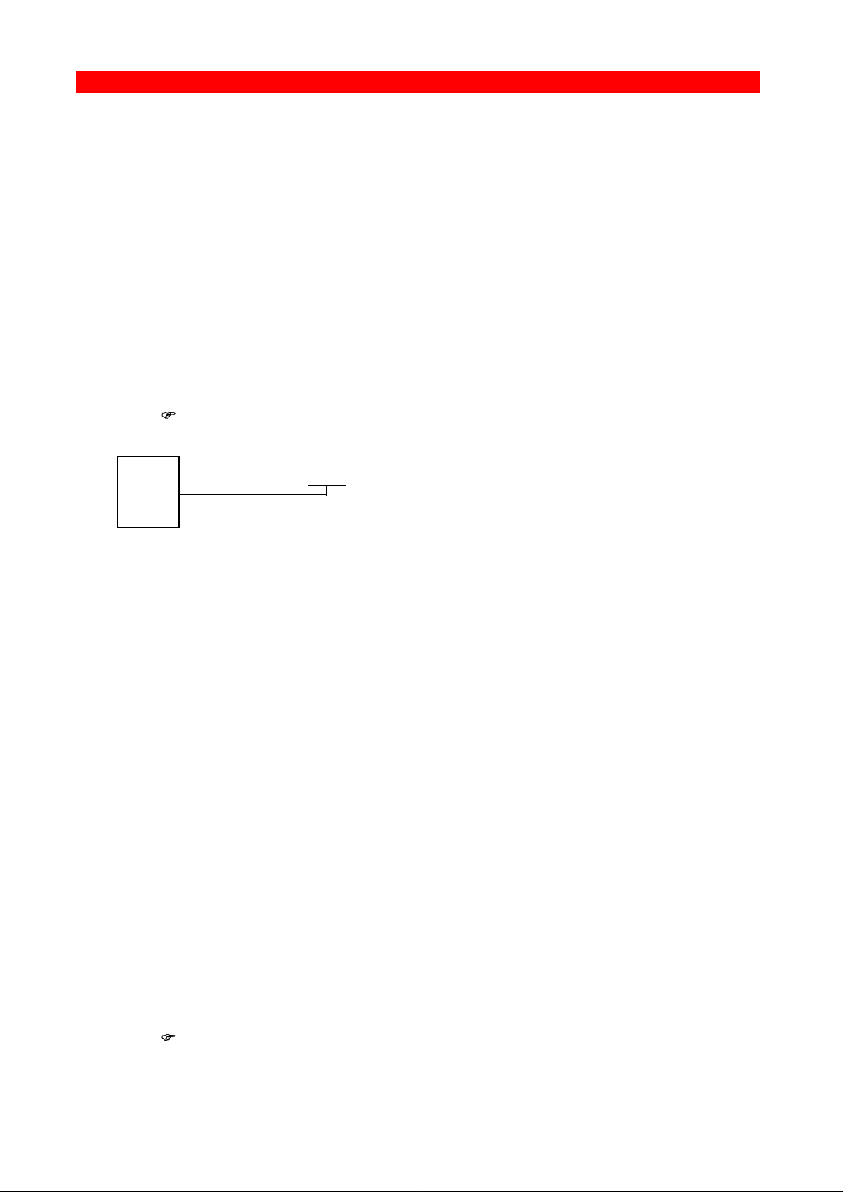
2.1. The Rear Panel
RS232
A = PCL B = FSL (default)
Fig 2-1 Xerox FS 3270 Rear Panel
B
A
T
PARALLEL IN PARALLEL OUTTEST
COAX
The coax cable is connected to the host which communicates in
accordance with the 3270 protocol.
PARALLEL OUT
The parallel output port is connected to the parallel/Centronics input port
on the target printer (standard parallel out cable supplied with printer
should be used).
PARALLEL IN
The parallel input port can be connected to the parallel/Centronics output
on a PC or similar source able to share the printer with the host. For this
connection you need a spare part cable ending in a 25-pole D-Sub
connector (i-data order no. 999022-030).
12-18 VDC.
+ --
0.7A
ROTARY (TEST) SWITCH
Testing and emulation switch which is read at power-up. Default
emulation is PCL (A).
PCL printer driver = A position. (Default is outside of B, A & T position)
FSL printer driver = B position.
- 10 -
Page 11

Connecting to System
Xerox FS 3270, User's Guide
(The “T” position is used for testing purposes. See the section on testing
later on in the manual.)
CAUTION:
When delivered, the switch is in neither the B, A or T position,
but is nevertheless set to PCL as a default. To change the
driver, it is very important you follow the instructions below in
the “Changing the Printer Driver” section. Note that operating
position is always away from the B, A or T position.
Changing the Printer Driver
To change from PCL to FSL driver or vice versa, first of all the rotary
switch has to be in position T at power on. The current printer driver will
be indicated on a printout. The actual selection of printer driver is then
made by turning the rotary switch to position A (PCL) or B (FSL). The new
position will be indicated as either “PCL” or “alternate printer driver” (FSL)
on a second printout. When the correct position is obtained, turn the
rotary switch away from the A, B or T positions (any other position will do).
Power the unit off then on again. The new driver is now active.
NOTE:
Emulation change results in the interface being reset to factory
default.
SERIAL (IN/OUT) RS232
The serial port can be configured either as input or as output.
Default configuration is input.
Serial input
The serial port is connected to the serial output on a PC or similar source
able to share the printer with the host.
For this connection you need a spare cable ending in a 25-pole RS
connector (i-data order no. 999010-030).
To use RS input Function 24, the "Data Input/Output Port Select" must be
set to zero (which is factory default).
On the PC you must also make the following settings to match the default
settings on the box:
Baud rate = 9600
Number of data bits = 8
Parity = None
Stop Bits = 1
If this is not possible, you must change functions 15, 16, 17 and 18 on the
box to match the PC's values.
- 11 -
Page 12

Connecting to System
Xerox FS 3270, User's Guide
NOTE:
Programming of functions 15, 16, 17, 18 and 24 is not possible
via the serial port. These functions have to be programmed
either via the coax or via the parallel input port.
2.2. Upgrading to IPC
If you need to upgrade your Xerox FS 3270 with the IPC module, please
follow these instruction before proceeding with the installation.
1. Unscrew the 4 screws from the bottom of the converter.
2. Place you hands on each side of the box, bottom facing down and the
rear panel facing you. Carefully press open the top cover of the
converter.
3. Place the IPC module (main component side facing up) on the PCB of
the box. Note that the connector has to be placed on top of the PCB’s
connector (to the right on the PCB).
4. Make sure the plastic supports fit in the holes of the IPC module.
5. Press the module gently into position and, while still facing the rear
panel, place the top cover precisely above the bottom cover so that all
edges are aligned. Press the top cover gently into a locked position.
6. Re-insert the screws and fasten.
7. Now proceed to the actual installation of the converter to the printer
and the system.
2.3. Connecting the Xerox FS 3270 to the Printer
CAUTION:
All connections to the Xerox FS 3270 protocol con verter
should be made while the power is switched OFF.
- 12 -
Page 13

Connecting to System
Xerox FS 3270, User's Guide
2.3.1. Connecting via Centronics output
Connecting the Xerox FS 3270 to the printer is simple and should cause
no problems if you just follow these steps:
1. Check that printer's parallel input port is available on printer.
2. Connect the cable supplied with the converter between the printer's
parallel port and the protocol converter's PARALLEL OUT port.
3. Power ON the printer and the Xerox FS 3270 box.
4. Make a settings printout by turning the rotary switch to the “T”
position and back to the original position. This will generate a
settings printout. The CU indicator will start flashing for
approximately 30 seconds.
Compare the test printout (FSL or PCL printout) with the relevant
printout in Chapter 10, Test Printout .
When the printout has the same format as shown in Chapter 9,
the connection between the Xerox FS 3270 converter and the
printer is working correctly.
Keep the settings printout together with this manual for future
reference
If the printout format does not match the test printout in Chapter 9
or if nothing was printed, this means that the printer setup does
not match the protocol converter setup. Contact your systems
support personnel or your i-data dealer.
5. When the printout is in order, you proceed to section 2.3,
"Connecting Xerox FS 3270 to System".
2.3.2. Connecting via RS-232 output
Note: This does not apply for Xerox FS 3270 IPC
1. Please note that if you change switch setting for emulation, the box
will be reset to factory default.
2. The cable you need for connecting the serial output device to the
serial port on the box must be ordered from your i-data dealer
especially for the serial output device.
3. Function 24 "Data Input/Output Port Select" has to be set to 1.
- 13 -
Page 14

Connecting to System
Xerox FS 3270, User's Guide
If possible, the serial output device you are connecting has to be set
to Baud rate = 9600, Number of data bits = 8, Parity = None and
Stop Bits = 1 to match the default settings of the box. If this is not
possible, you must change functions 15, 16, 17 and 18 on the box to
match the settings of the serial output device.
NOTE:
Programming of Functions 15, 16, 17, 18 and 24 is not
possible via the serial port. These functions have to be
programmed either via the coax port or via the parallel
input port.
For full details on Y functions, please see the Laser 3270
Programmer's Guide; Document No.: D62078, subpart D62071.
4. Power on the printer and the Xerox FS 3270 box.
5. Make a settings printout by turning the rotary switch to the “T”
position and back to the original position. This will generate a
settings printout. The CU indicator will start flashing for
approximately 30 seconds.
Compare the test printout (FSL or PCL printout) with the rele vant
printout in Chapter 10, Test Printout.
When the printout has the same format as shown in Chapter 9, the
connection between the Xerox FS 3270 converter and the printer is
working correctly.
Keep the settings printout together with this manual for future
reference.
6. If the connection between the printer and the protocol con verter
does not work properly, the reason is probably that the Y function 24
is not set to serial out or that the functions 15, 16, 17 and 18 do not
match the values of the printer.
If the printout format does not match the test printout in Chapter 9, or
if nothing was printed, this means that the printer setup does not
match the protocol converter setup. Contact your systems support
personnel or your i-data dealer.
- 14 -
Page 15

Connecting to System
Xerox FS 3270, User's Guide
7. Power the Xerox FS 3270 OFF and back ON and check that all
indicators light up momentarily. (The indicators are described in
Section 3.1, Indicator LEDs).
8. Proceed to section 2.3 Connecting Xerox FS 3270 to the System.
2.4. Connecting the Xerox FS 3270 to the System
After a successful test printout has been generated to ensure that the
connection between the Xerox FS 3270 converter and the printer is
working correctly (see previous section), you are now ready to connect
the Xerox FS 3270 to the system.
CAUTION:
All connections to the Xerox FS 3270 protocol con verter
should be made while the power is switched OFF.
1. Turn off the power and connect the Xerox FS 3270 to your host
system using the coax cable.
2. When the connection has been made, turn power ON and check that
the CU and READY indicators turn ON. When it does, you have
completed the installation procedure and are ready to operate the
protocol converter as described below.
What if the CU Indicator fails to turn on?
If the CU indicator does not turn ON, this means that there is no
communication with the control unit. You should check the following:
a. The coax cable connection from the control unit to the Xerox FS
3270 .
b. The control unit (is it powered up etc.)
c. Is the control unit supported by the Xerox FS 3270 (See Section
1.3, Supported Control Units, for a list of supported control
units).
- 15 -
Page 16

Connecting to System
Xerox FS 3270, User's Guide
If all three (a. b. and c.) are in order, contact your systems support
personnel or your dealer.
PCL driver:
The default configuration of the interface will suffice for most
application programs and uses. You should only change the
configuration if you have special requirements.
If you should wish to change the configuration, the options may be
set from the line as described in the Programmer's Guide;
document no. D62078, subpart D62030
FSL Driver
With the FSL driver you have selected an unprogrammed printer
driver. You have to program the internal setup of the box to suit
your printing requirements. See Programmer's Guide; document
no. D62078, subpart D62071 for further details.
2.4.1. Testing
1. Power the unit ON.
2. Turn the rotary switch to the “T” position and back to the original
position. This will generate a settings printout.
3. When the switch has been turned back to its original position, the
CU indicator will start flashing for approximately 30 seconds.
4 Turn the rotary switch to the “T” position once again while the CU
indicator is flashing. The unit will now enter Online HEX dump
mode. The dump mode is terminated by turning the switch away from
the “T” position and back into the “T” position.
NOTE:
The CU indicator will be blinking rapidly while the rotary
switch is in the “T” position. This is an indication that the
“T” position is not a valid permanent position.
5. Compare the test printout (FSL or PCL printout) with the rele vant
printout in Chapter 10, Test Printout.
- 16 -
Page 17

Connecting to System
Xerox FS 3270, User's Guide
Keep the settings printout together with this manual for future
reference.
Settings Printout at Power-on (PCL mode only)
A settings printout can also be generated at power-on by activating
function Y120.
NOTE:
The Rotary Switch has to be activated at power on in order to
change from FSL to PCL or back.
2.4.2. Timeout
The Xerox FS 3270 enables printer sharing between the system and a
PC. For this purpose it is possible to specify a timeout period.
If the printer is receiving input on the parallel port, for example, and there
is a break in the transmission of data, the other input ports will not be
polled for the period speci fied.
The factory default timeout is 20 seconds. The timeout may be changed to
suit your requirements. This is done by sending a new setup to the Xerox
FS 3270 input port where you want it to take effect. See Chapter 5.
Specifying Timeout.
When specifying the timeout it is also possible to specify a user string. A
user string may be used for changing from one symbol set (e.g. Roman 8)
to another (e.g. IBM-PC8), for example.
NOTE:
Settings on the coax input port are automatically reestablished
after another input port has been using the printer.
On the parallel and RS input port, you have to program the
required setup yourself.
For more detailed information on the commands required, see Chapter 4,
Specifying Timeout.
- 17 -
Page 18

Operation
3.
3.1.
Xerox FS 3270, User's Guide
Operation of Xerox FS 3270
The Xerox FS 3270 top panel has been designed to register the
operation of the box via the four following indicator LEDs :
• CU (contact to Control Unit)
• PAR (parallel input)
• SER (serial input)
• READY (printer)
The Indicators of the Xerox FS 3270
CU (Contact with Control Unit)
This indicator LED has 3 states:
State Indication
ON
BLINKING
OFF
Contact with the control unit.
1. Contact with the control unit, and data pending
in the Xerox FS 3270 buffer.
2. Indicates that the TEST switch has been
activated and the box is ready to enter on-line
HEX dump mode
3. The CU indicator will be blinking rapidly while
the rotary switch is in the “T” position. This is an
indication that the “T” position is not a valid
permanent position.
No contact to the control unit, or the contact has
been broken for more than 1 minute.
PAR (Parallel input)
The indicator LED has 2 states:
State Indication
ON
OFF
Indicates that the box is processing data from the
Centronics parallel port
Indicates that the box is idle or processing data
from the coax/RS inputs
- 18 -
Page 19

Operation
Xerox FS 3270, User's Guide
SER (Serial input)
The indicator LED has 3 states
State Indication
ON
Indicates that the box is processing data from the
RS-232 Serial input
BLINKING
Indicates that the box has defined the RS-232 as
output for the box.
OFF
Indicates that the box is idle or is processing data
from the coax/Centronics inputs.
READY (Printer Ready)
The indicator LED has 3 states:
State Indication
ON
Indicates that the connected printer is ready; i.e.
that printer's "Select" condition is active and the
"PE" signal is inactive. If the connected printer is
an RS 232 printer, the ready validation is done by
the "DTR" signal.
OFF Indicates that the connected printer is not ready
for data input.
BLINKING Indicates a not-ready condition
- 19 -
Page 20

Specifying Timeout
Xerox FS 3270, User's Guide
4. Specifying Timeout
In order to specify the timeout for a specific input port, an FSL ( Function
Selection via the Line) sequence must be sent to the port in question. To
do this a temporary Escape (ESC) Character must be defined first. This is
done in the following way:
&&??<character>
The sequence "&&??%" will define "%" as the ESC Character.
Timeout is specified in FSL Function 100 . This function has the following
syntax ("%" is the ESC Character):
%Y100,<timeout>[,user string]%
Factory default = 20 seconds
Timeout: 0 to 255 indicating number of seconds
User string: Optional - string in HEX to be sent to the printer before
transmission of data, when the printer is selected by the
share unit.
If function 100 is sent to the coax, a user string number
can be defined instead of a HEX string. The user string
then has to be defined in function 61.
NOTE:
The Timeout string must be written in ONE line (see example
overleaf).
The user string and settings will only be sent if a share condition has
occurred.
- 20 -
Page 21

Specifying Timeout
RAM
Xerox FS 3270, User's Guide
NVRAM=
Non-volatile
The new setup must be saved in the NVRAM with the following command
("%" is the ESC Character):
%X1
The FSL string above was split up into several lines for reasons of
clarification to simplify the explanation of the different functions. Below is
an example where the FSL string is typed in one line.
Example:
&&??%%Y100,30,1B,45%%X1
The FSL string above has the following effect:
• Defines % as ESC character
• Sets timeout to 30 seconds
• Send 1B 45 HEX (RESET) before the next data transmissi on.
• Saves setup in the NVRAM.
NOTE:
FSL 100 works on the port it is sent to. If it is sent to the parallel
or RS input port, the string containing the Function 100
programming will be printed when it is sent to the Xerox FS
3270 .
- 21 -
Page 22

idaSetup - IPC Programming
Xerox FS 3270, User's Guide
5. idaSetup - IPC Programming
NOTE:
This chapter only applies to the converter when
mounted with an IPC module.
idaSetup is a program developed with the purpose of setting up the wide
range of IPC protocol converters via a PC share port or from a host.
For details on how to configure the IPC parameters for the
Xerox FS 3270 IPC using the program idaSetup, see the
separate documentation for this, “IPDS Programmer’s Guide”,
doc. no. D60253. The manual is available as an electronic
document.
- 22 -
Page 23

Programming
Xerox FS 3270, User's Guide
6. IRQ Handling
This section describes how to recover from various IRQ conditions.
• Paper jam
• Out-of paper
• Stacker full
The printer will recover from these conditions without loss of data as long
as you do not power off the printer.
• Printer Not READY
The Xerox FS 3270 IPC will detect if the printer is NOT READY and will
interrupt data transmission to the printer. If the printer is OFFLINE (i.e. not
READY) there will be no data loss as long as you do not power off the
printer.
• Out of toner
This condition is indicated by the printer's front panel. If printing
continues, the print quality may not be acceptable. There will be
no loss of data as long as you do not power off the printer
.
• Door Open
This condition is indicated by the printer's front panel. There will be
no loss of data as long as you do not power off the printer
• Printer Power Off
You should not power off the printer, unless you power off the box as well.
If only the printer is powered off, unpredictable results may occur.
- 23 -
Page 24

Programming
Xerox FS 3270, User's Guide
7. Programming Xerox FS 3270 - non-IPC
The Xerox FS 3270 works using approximately 60 internal Setup
Functions (FSL Functions). When the protocol converter has been
installed and connected to a printer, you may have to consider the use of
these setup options.
FSL setup functions can be sent either from your IBM system or from a PC.
PCL Driver (Default)
If you have decided to run the Xerox FS 3270 in PCL mode (see Chapter
1), the Xerox FS 3270 is ready to operate after you have completed the
installation procedure. The factory default setup will meet the demands of
most host systems and users, and special programming is therefore
normally not required.
FSL Driver
However, special circumstances may require changes in the programming
of the box. For full details on this please see the "Laser 3270
Programmer's Guide; D62078, subpart D62030. In the Programmer's
Guide you will find an extensive description of the FSL Functions with
notes, comments and examples.
If you have decided to run the Xerox FS 3270 in FSL mode (see Chapter
1), you have just selected an unprogrammed printer driver and you need
to program any further settings of the box using FSL functions. The "Laser
3270 Programmer's Guide"; Document No. D62078, subpart D62071
gives you full details on how you do this.
On the following pages you will find a list of the functions
available in PCL mode and FSL mode respectively.
- 24 -
Page 25

Programming
Xerox FS 3270, User's Guide
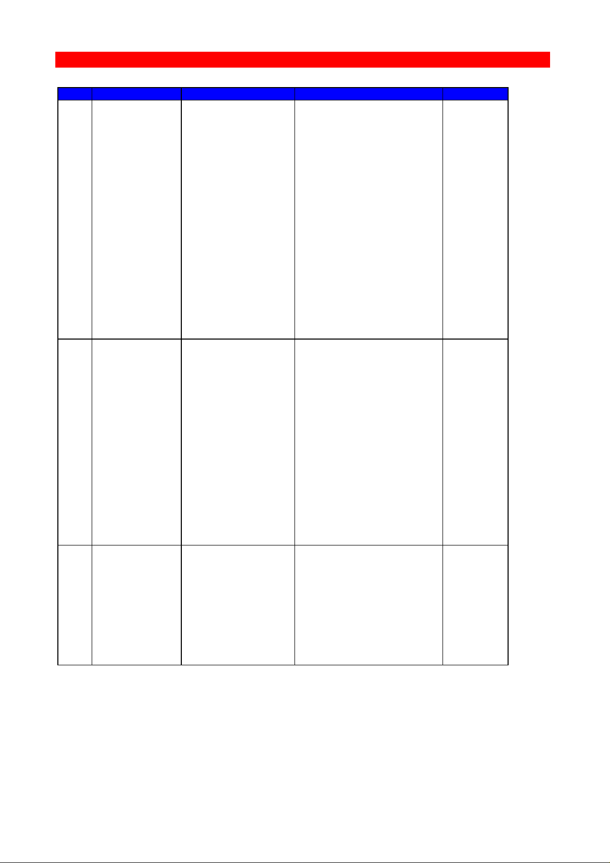
7.1. Setup Functions Supported in PCL mode
Y1 Set IBM Buffer Size
Y2 Set Default LPI
Y3 Set Default CPI
Y4 Set Default Line Spacing
Y5 Set Default Page Length (MPL)
Y6 Set Default Max. Print Position (MPP)
Y7 Set Case (Mono,Dual)
Y8 Set LU1 Language
Y10 Set Page Format
Y11 Set Default Paper Path
Y12 Set Default Paper Size
Y13 Line Overflow Condition
Y14 Enable Graphics Option (idaAFP)
Y15 RS-232 Baud Rate
Y16 RS-232 Word Length
Y17 RS-232 Parity
Y18 RS-232 Stop Bit
Y19 Set Simplex/Duplex
Y22 Printer Driver Selection
Y24 Serial Input/Output
Y25 FF Before Local Copy
Y26 FF After Local Copy
Y27 NON-SCS Print Image
Y28 NON-SCS, CR at MPP+1
Y29 NON-SCS, NL at MPP+1
Y30 NON-SCS, Valid FF Followed by data
Y31 NON-SCS, Valid FF at end of buffer
Y32 NON-SCS, FF Valid
Y33 NON-SCS, Automatic Func. at end of job
Y34 Last LF on page sent as FF
Y36 Suppress IBM control codes (parameters 0 and 1)
Y37 IBM Printer Emulation Select (parameters 0,1,2 & 4)
Y38 IBM Communication Feature (Query, EAB)
Y41 Generation of NL at EM
Y44 Suppress CR and SP
Y46 Set IRQ Timer
Y47 ESC Mode Selection
Y48 Set Permanent ESC Character
Y49 Restrict access of NVRAM settings
Y50 FF After Time Elapse
Y51 User-defined string(s) at Power-on
Y57 User-defined string before local copy
Y58 User-defined string after local copy
Y59 Bar Code Type Definition
Y60 Font Link
- 25 -
Page 26

Programming
Xerox FS 3270, User's Guide
Y61 Setup for user-defined strings (parameters 0 - 7)
Y62 Setup for IBM defined strings
Y63 Define Logo
Y72 Reset Translate Table
Y73 Select Translate Table
Y74 Printer Symbol Set Definition Strings
Y75 Overwrite Translate Table
Y77 Reset APL Translate Table
Y78 Select APL Translate Table
Y79 ida 820 AFP Font Offset
Y80 Overwrite APL Translate Table
Y88 Margin Definition (idaAFP only)
Y89 Enable Margin Definition
Y90 Define User Escape String
Y91 Font Definition
Y92 Font Point Size Definition Strings
Y93 Font Attribute Definition
Y94 Font Typeface Definition
Y96 Font Change Simulation
Y98 Automatic Page Orientation
Y100 Port Sharing Option
Y110 idaAFP Orientation Support
Y111 idaAFP Duplex Support
Y112 idaAFP PCL5 Font Support
Y113 idaAFP Early Print Complete
Y114 idaAFP Colour Support
Y115 idaAFP Miscellaneous
Y118 Expanded Printable Area
Y119 Autoconfiguration Select
Y120 Print Test Page at power on
ESC Features:
%% Special transparent feature (Multiple paired Hex transparent).
e.g.: %%1B45%
where % is the defined ESC character.
% Special transparent feature (Single paired Hex transparent).
where % is the defined ESC character.
Send Logo:
L Send logo (Logo is defined in Y63).
- 26 -
Page 27

Programming
Xerox FS 3270, User's Guide
TEST functions (T-Functions):
T1 Offline Hex Dump (PCIA Dump)
T2 Online Hex Dump
T3 Online ASCII Hex Dump
T4 Print out Settings
T5 Printout Character Set
T6 Cancel Online ASCII Hex Dump
User Settings Functions (X-Functions):
X1 Store Settings in Permanent Storage
X2 Restore Settings from Permanent Storage
X3 Restore Factory Default Settings
X4 Restore Settings from Permanent Storage
X5 Restore Settings (SCS settings will be retained)
Engineering Functions:
Y249 Enable Engineering Mode
Z Functions:
Zn Send user-defined string
W Functions:
Wn Printing Barcodes (defined in Y 59)
- 27 -
Page 28

Programming
Xerox FS 3270, User's Guide
7.2. Setup Functions Supported in FSL mode
Y1 Set IBM Buffer Size (parameters 2,3,4 & 5)
Y2 Set Default LPI (parameters 6 & 8)
Y3 Set Default CPI (parameters: 10, 12, 15 & 16)
Y5 Set Default Page Length (MPL)
Y6 Set Default Max. Print Position (MPP)
Y7 Set Case (Mono,Dual)
Y8 Set LU1 Language
Y9 Set Default Print Quality (parameters 2 & 3)
Y11 Set Default Paper Path (parameters 1, 2 & 3)
Y14 Enable Graphics Option (idaAFP) (parameters 0 & 1)
Y15 RS-232 Baud Rate
Y16 RS-232 Word Length
Y17 RS-232 Parity
Y18 RS-232 Stop Bit
Y24 Serial input/output
Y25 FF Before Local Copy
Y26 FF After Local Copy
Y27 NON-SCS Print Image
Y28 NON-SCS, CR at MPP+1
Y29 NON-SCS, NL at MPP+1
Y30 NON-SCS, Valid FF Followed by data
Y31 NON-SCS, Valid FF at end of buffer
Y32 NON-SCS, FF Valid
Y33 NON-SCS, Automatic Func. at end of job
Y34 Last LF on page sent as FF
Y35 FF from system sent as FF or LF's
Y36 Suppress IBM control codes
Y37 IBM Printer Emulation Select
Y38 IBM Communication Feature (Query, EAB)
Y39 Suppress Empty Forms
Y44 Suppress CR and SP
Y46 Set IRQ Timer
Y48 Set Permanent ESC Character
Y49 Restrict access of EEPROM settings
Y50 FF After Time Elapse
Y51 User-defined string(s) at Power-on
Y52 User-defined string(s) at Printer Power down/ Printer Error
Y53 User-defined string before Error Message
Y54 User-defined string after Error Message
Y55 Barcode type select
Y56 Barcode Entry
Y57 User-defined string before local copy
Y58 User-defined string after local c opy
Y61 Setup for user-defined strings
- 28 -
Page 29

Programming
Xerox FS 3270, User's Guide
Y62 Setup for IBM defined strings
Y63 Define Logo
Y71 Create Translate Table
Y72 Reset Translate Table
Y73 Select Translate Table
Y75 Overwrite Translate Table
Y76 Create APL Translate Table
Y77 Reset APL Translate Table
Y78 Select APL Translate Table
Y80 Overwrite APL Translate Table
Y88 Margin Definition (idaAFP only)
Y89 Enable Margin Definition (idaAFP only)
Y90 Define User Escape String
Y100 Port Sharing Option
Y120 Settings Printout at Power Up
ESC Features
%% Special transparent feature (Multiple paired Hex transparent).
e.g.: %%1B45%
where % is the defined ESC character.
% Special transparent feature (Single paired Hex transparent).
where % is the defined ESC character.
Send Logo:
L Send logo (Logo is defined in Y63).
TEST functions (T-Functions):
T1 Offline Hex Dump (PCIA Dump)
T2 Online Hex Dump
T3 Online ASCII Hex Dump
T4 Print out Settings
T5 Printout Character Set
T6 Cancel Online ASCII Hex Dump
- 29 -
Page 30

Programming
Xerox FS 3270, User's Guide
User Settings Functions (X-Functions):
X1 Store Settings in Permanent Storage
X2 Restore Settings from Permanent Storage
X3 Restore Factory Default Settings
X4 Restore Settings from Permanent Storage
Engineering Functions:
Y249 Enable Engineering Mode
Z Functions:
Zn Send user-defined string
- 30 -
Page 31

FSL Setup via PC's Parallel Port
Xerox FS 3270, User's Guide
8. FSL Setup via Xerox FS 3270 Serial or Parallel Port
FSL support on the serial or parallel input port is defined by temporary
escape character, FSL Y100 and ESC X1.
The Engineering Function Y249 (FSL setup via share port) allows you to
program the FSL parameters for coax input directly via the serial or
parallel input port.
When FSL programming is preceded by FSL Y249, the Xerox FS 3270
will interpret the FSL as sent via the coax line.
Example:
&&??%%Y100,10,’SHARESTRING’%%X1
Sent to the serial or parallel input port, this command string will program
FSL Y100 on the serial or parallel input port it was sent to.
&&??%%Y249,PASSWORD%%Y100,10,’SHARESTRING’%%X1
Sent to the serial or parallel input port, this command string will program
FSL Y100 on the coax port.
In the description below, it is assumed that you know how to define an
escape character (this must be done before you can use the Y249
function).
Character conversion
When the engineering function is received, all the following characters in
the Xerox FS 3270 are converted to LU3 characters.
The characters are now interpreted as received by the coax line.
This functionality is automatically deactivated after timeout on the share
port used.
NOTE:
To ensure correct conversion of the characters following the
engineering function, use characters existing in the symbol set
PC-850 for coax.
- 31 -
Page 32

FSL Setup via PC's Parallel Port
Xerox FS 3270, User's Guide
Activating the Y249 Engineering Function
Before the Engineering Function can be activated, an Escape character
must be defined (see section 5 for details on how to do this).
If you have defined % as Escape CHARACTER, you activate the
engineering function by typing:
%Y249,n%
n = password. As this is sensitive information, system operators can
contact their i-data distributor for password details.
Deactivating the Y249 Engineering Function
The function will be deactivated automatically after timeout on the share
port used (timeout is defined in Y100 Port Sharing Option).
Limitations when Y249 is active
Characters not present in the PC-850 symbot set (Coax) can still be sent
in hex notation.
Example:
If you need to define user string 1 containing a PCL reset, then define the
following:
&&??%
%Y249,PASSWORD%
%Y61,1,1B45%
%X1
- 32 -
Page 33

FSL Setup via PC's Parallel Port
Xerox FS 3270, User's Guide
8.1. Updating Firmware
The Xerox FS 3270 firmware (complete firmware) may be updated either
via the coax line or via centronics input port. For further in formation
please contact your i-data distributor.
If errors are detected, the downloading will be terminated and an error
message will be printed if possible. If serious errors occur during
programming, the firmware has to be downloaded via the share port.
The downloading of firmware is considered complete if no data is received
within 30 seconds. The interface will then make a soft re set.
NOTE:
In case of damaged FLASH PROM, try the following procedure:
Boot Download of firmware:
1. Turn the power off
2. Place the rotary switch in the “B” position
3. Turn the power on and note that the READY LED is lit
4. Download the boot firmware (Syntax: “Copy 140.xxx.1 /b”)
5. Download the new firmware. When download is completed and the FLASH
PROM is programmed, the LED will start flashing
6. Turn off the power and set the rotary switch in a position different from “A”,
“B” or “T” before turning on the power again.
- 33 -
Page 34

Error Messages
Xerox FS 3270, User's Guide
9. Error Messages
Errors fall into two categories: the operator-recoverable errors and the
non-recoverable hardware errors.
The error messages listed below are all printed out on paper when the
error situation arises (provided the printer is on-line).
You correct the errors from the host system in accordance with the error
messages given.
9.1. Recoverable Errors
The error messages are listed in alphabetical order below.
BARCODE IS DISABLED
ESCAPE SEQUENCE ERROR
NOT NUMBER
ESC X IS WRONG
ESCAPE SEQUENCE ERROR
ESCAPE SEQUENCE ERROR
NUMERICAL OVERFLOW
ESCAPE SEQUENCE ERROR
CREATE TRANSLATE TABLE
OUT OF RANGE. MAX 8' 13
ESCAPE SEQUENCE ERROR
NO TRANSLATE TABLE
CREATED
ESCAPE SEQUENCE ERROR
NO TRANSLATE TABLE
APL
CREATED
- 34 -
Page 35

Error Messages
Xerox FS 3270, User's Guide
ESCAPE SEQUENCE ERROR
TRANSLATE TABLE LOAD
CHARACTER IS OUT OF RANGE
VALIDATION VALUE IN NVRAM IS WRONG
VALUES ARE NOW OVERWRITTEN WITH FACTORY
DEFAULTS
ESCAPE SEQUENCE ERROR
ILLEGAL SEPARATOR
FUNCTION (NO) IS NOT SUPPORTED
ESCAPE SEQUENCE ERROR
ESC Y
MULTISTRIKE STRING IS TOO LONG
Not in engineering mode
NVRAM VERIFICATION ERROR IN CELL
PARAMETER IS OUT OF RANGE
PASSWORD IS NOT ACTIVE
SYNTAX ERROR IN CALL. FUNC = (NO)
THE CONTENTS OF NVRAM HAS BEEN DAMAGED
VALUES ARE NOW OVERWRITTEN WITH FACTORY
DEFAULTS
There is no password
THE NVRAM IS ALREADY LOCKED, PASSWORD IS IGNORED
THE PASSWORD TO OPEN NVRAM AREA IS WRONG
THE PASSWORD IS TOO LONG
THE SELECTED BARCODE IS NOT SUPPORTED
The NVRAM is locked
The dynamic area is locked
The checksum in the NVRAM is wrong
THERE IS NO SPACE LEFT
IN THE DYNAMIC AREA
THE USER ADDRESS STRING IS TOO LONG
- 35 -
Page 36

Error Messages
Xerox FS 3270, User's Guide
TERMINATOR NOT ACCEPTED
ESC Z IS WRONG
Validation value in NVRAM is wrong
YOU CANNOT LOCK THE NVRAM
BEFORE YOU HAVE PROGRAMMED IT
9.2. Non-Recoverable Hardware Errors
The following recovery attempt can be made:
• Turn power OFF for 10 seconds and then ON again. If the
problem persists, seek technical assistance.
The non-recoverabel error messages consist of this message:
HARDWARE MALFUNCTION. Call for service.
followed by one of these diagnostic messages:
COAX IF ram error
Wrong data in selftest
Wrong word in selftest
Nothing received in selftest
8085 ram error
Rom check sum error
Response missing from COAX IF
Invalid test response from COAX IF
- 36 -
Page 37

Test Printouts
Xerox FS 3270, User's Guide
10. Test Printouts
PCL Test Printout
Xerox FS 3270 PCL, Version: S10 xxx.xxx /00963001
Boot ID: 80010004
Temporary Escape code = 2E Hex, Character = '%'. Tray = A4
Dynamic area size: 2048 bytes, 333 bytes used, 1715 bytes free.
Function 1: is set to 4
Function 2: is set to 6
Function 3: is set to 10
Function 5: is set to 66
Function 6: is set to 132
Function 7: is set to 1
Function 8: is set to 0
Function 10: is set to 0
Function 11: is set to 2
Function 12: is set to 1
Function 13: is set to 1
Function 14: is set to 1
Function 15: is set to 5
Function 16: is set to 8
Function 17: is set to 1
Function 18: is set to 1
Function 19: is set to 0
Function 22: is set to 5
Function 24: is set to 0
Function 25: is set to 0
Function 26: is set to 1
Function 27: is set to 0
Function 28: is set to 0
Function 29: is set to 0
Function 30: is set to 1
Function 31: is set to 1
Function 32: is set to 0
Function 33: is set to 0
Function 34: is set to 1
Function 36: is set to 0
Function 37: is set to 1
Function 38: is set to 1
Function 41: is set to 1
Function 44: is set to 1
Function 46: is set to 12
Function 47: is set to 1
Function 49: is set to 0
Function 50: is set to 0
Function 73: is set to 0
Function 78: is set to 1
Function 79: is set to 0
Function 89: is set to 0
Function 98: is set to 1
Function 110: is set to 1
Function 111: is set to 0
Function 112: is set to 0
Function 113: is set to 1
Function 114: is set to 0
Function 115: is set to 1
Function 118: is set to 0
Function 119: is set to 0
Function 120: is set to 0
BUSY TIMEOUT: 240
TIMEOUT COAX, C,RS: 20,20,20
- 37 -
Page 38

Test Printouts
Xerox FS 3270, User's Guide
Default GFID:
10 CPI= 11, 13 CPI = 204
12 CPI= 80, 20 CPI = 281,
15 CPI= 223, 27 CPI = 290
16 CPI = 253,
PROPORTIONALLY SPACED = 1412 AFP TOP MARG. = 0 : 0
ACTIVE GFID = 11 AFP LEFT MARG. = 0 : 0
USER STRING #6 = 1B,26,6C,30,4F
USER STRING #7 = 1B,45
IBM Setup String(s):
130 1B,28,73,33,42
131 1B,28,73,30,42
BARCODES: 39,3,2;29,3,2;28,3,2;26,3,2;35,3,2;24,3,2;33,3,2;22,3,2
- 38 -
Page 39

Test Printouts
Xerox FS 3270, User's Guide
FSL Test Printout
Xerox FS 3270 FSL, Version: S10 xxx.xxx /00964002
Boot ID: 80010004
Temporary Escape code = 2E Hex, Character = '%'. Tray =A4
There are 2048 bytes available in the dynamic area.
299 bytes are in use, and 1749 bytes are free.
Function 1: is set to 4
Function 2: is set to 6
Function 3: is set to 10
Function 4: is set to 1
Function 5: is set to 72
Function 6: is set to 132
Function 7: is set to 1
Function 8: is set to 1
Function 9: is set to 1
Function 11: is set to 1
Function 14: is set to 0
Function 15: is set to 5
Function 16: is set to 8
Function 17: is set to 1
Function 18: is set to 1
Function 24: is set to 0
Function 25: is set to 0
Function 26: is set to 0
Function 27: is set to 0
Function 28: is set to 0
Function 29: is set to 0
Function 30: is set to 0
Function 31: is set to 0
Function 32: is set to 0
Function 33: is set to 0
Function 34: is set to 0
Function 35: is set to 0
Function 36: is set to 0
Function 37: is set to 1
Function 38: is set to 1
Function 39: is set to 0
Function 44: is set to 0
Function 46: is set to 12
Function 47: is set to 1
Function 49: is set to 0
Function 50: is set to 0
Function 55: is set to 1
Function 89: is set to 0
Function 100: is set to 20
Function 120: is set to 0
BUSY TIMEOUT: 240
TIMEOUT COAX, C,RS: 20,20,20
No user strings are sent at power on.
No user strings are sent after printer error.
No user strings are sent at user programming error.
No user strings are sent before local copy.
No user strings are sent after local copy.
Password is not activated.
- 39 -
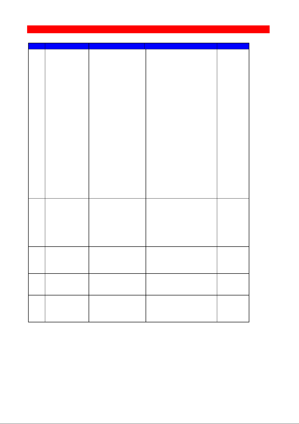
Page 40

Appendices
1
Buffer Size
%Y1,<n1>%
1 = 960 characters
2 = 1920 characters
3 = 2560 characters
*4 = 3440 characters
5 = 3564 characters
FSL: N/S
2
LPI
%Y2,<n1>%
0 = USER: No LPI
AUTO: Ignored
3 = 3 LPI
4 = 4 LPI
*6 = 6 LPI
8 = 8 LPI
For an explanation of
USER and AUTO modes,
see the "Laser 3270
Programmer's Guide"
FSL: N/S
FSL: N/S
FSL: N/S
3
CPI
%Y3,<n1>%
0 = USER: No CPI
AUTO: Prop.
spacing
*10 = 10 CPI
12 = 12 CPI
15 = 15 CPI
16 = 16.7 CPI
20 = 20 CPI
27 = 27 CPI
FSL: N/S
FSL: N/S
FSL: N/S
4
Line Spacing
%Y4,<n1>%
*1 = Single Space
2 = Double space
Y4:
PCL only
5
Form Length
%Y5,<n1>%
0 = Disable vertical
formatting
001to255 = Set FL in no.
of lines
*72 FSL
*66 PCL
**66 FSL
**62 PCL
6
Maximum
Print
Position
%Y6,<n1>%
0 = No NLs will be
generated by the
interface
001to255 = Set MPP in no.
of characters
*132
7
Case
%Y7,<n1>%
0 = Mono case (left
to right)
*1 = Dual case (left
to right)
2 = Right to left
(dual case)
3 = Left to right
(dual case)
Xerox FS 3270, User's Guide
Appendix A: Quick Reference Guide to
FSL Functions
* = Factory Default ** = Factory Default (US)
No. Name Syntax Parameters Deviations
- 40 -
Page 41

Appendices
8
LU1 Language
%Y8,<n1>%
*0 = Download LU1
language from
CU
1 = English US
EBCDIC
3 = Austrian/
German
4 = Belgian
5 = Brazilian
6 = Canadian
(French)
7 = Danish/
Norwegian
8 = Danish/
Norwegian Alt
9 = Finnish/
Swedish
10 = Finnish/
Swedish Alt
11 = French
13 = Austrian/
German Alt
14 = International
15 = Italian
16 = Japanese
(English)
19 = Spanish
20 = Spanish Alt
21 = Spanish speaking
22 = English UK
28 = Portuguese
30 = French
105-charact.
31 = Swiss German/
French
40 = Spanish Data/
Text
*0=PCL
*1=FSL
9
Print
Quality
%Y9,<n1>%
*1 = Draft Print
Quality
2 = Near Letter
Quality
3 = Correspondence
Y9:
FSL only
Xerox FS 3270, User's Guide
No. Name Syntax Parameters Deviations
- 41 -
Page 42

Appendices
10
Page Format
%Y10,<n1>[,n2]%
n1
*0 = Portrait
1 = Landscape
2 = COR 1
3 = Fit to page in
portrait
4 = 8" x 11"
Portrait
5 = 8" x 12"
Portrait
6 = 13.2" x 8.5"
Landscape
7 = Landscape
13.2"
8 = Portrait
10 cpi x 11"
9 = Portrait
10 cpi z 12"
n2
1 = Tractor (Upper)
2 = Drawer 1 (Upper)
3 = Drawer 2 (Lower)
4 = Manual feeder
5 = Envelope feeder
6 = Drawer 3 (Lower)
Y10:
PCL only
11
Paper Path
%Y11,<n1>%
0 = Ignore PPM and
select tray
from printer
front panel
1 = Tractor (Upper)
*2 = Drawer 1
3 = Drawer 2
4 = Manual feeder
5 = Envelope feeder
6 = Drawer 3
FSL: N/S
1=FSL
2=PCL
FSL: N/S
FSL: N/S
FSL: N/S
Xerox FS 3270, User's Guide
No. Name Syntax Parameters Deviations
- 42 -
Page 43
Appendices
12
Paper Size
%Y12,<n1>[,n2]%
n1
*1 = A4
2 = Legal
**3 = Letter
4 = Executive
5 = Letter
(Monarch)
6 = Business
(Com 10)
7 = International
DL
8 = International
C5
10 = A3
n2
1 = Tractor (Upper)
2 = Drawer 1 (Upper)
3 = Drawer 2 (Lower)
4 = Manual feeder
5 = Envelope feeder
6 = Drawer 3 (Lower)
Y12:
PCL only
13
Line
Overflow
Option
%Y13,<n1>[,n2]%
n1
0 = Lines longer
than print line
are wrapped.
Overflow data
on next line.
*1 = Lines longer
than print line
are cut.
Overflow data
is not printed.
n2
1 = Tractor (Upper)
2 = Drawer 1 (Upper)
3 = Drawer 2 (Lower)
4 = Manual feeder
5 = Envelope feeder
6 = Drawer 3 (Lower)
Y13:
PCL only
14
Enable
Graphics
%Y14,<n1>%
0 =Disable graphics
*1 =Enable graphics
2 =Disable graphics
(and no error de-
tection at mode
changes)
3 =Enable graphics
(and no error de-
tection at mode
changes)
0=FSL
1=PCL
FSL: N/S
FSL: N/S
Xerox FS 3270, User's Guide
No. Name Syntax Parameters Deviations
- 43 -
Page 44

Appendices
15
Baud Rate
for Serial
Input
%Y15,<n1>%
n1
0 = 300 Baud
1 = 600 Baud
2 = 1200 Baud
3 = 2400 Baud
4 = 4800 Baud
*5 = 9600 Baud
6 = 19200 Baud
16
No. of Data
Bits for
serial input
%Y16,<n1>%
n1
7 = 7 bits
*8 = 8 bits
17
Parity for
serial input
%Y17,<n1>%
n1
0 = odd parity
*1 = no parity
2 = even parity
18
No. of Stop
Bits for
serial input
%Y18,<n1>%
n1
*1 = 1 stop bit
2 = 2 stop bit
19
Duplex
Printing
%Y19,<n1>%
*0 = Simplex
1 = Long-edge duplex
2 = Short-edge duplex
Y19:
PCL only
22
Printer
Driver
Selection
%Y22,<n1>%
*5 = PCL 5 driver.
Disable ida AFP
query.
15 = PCL 5E driver
Enable ida AFP
query.
Y22:
PCL only
24
Interface
Selection
%Y24,<n1>%
*0 = Port 0
1 = Port 1
25
FF before
Local Copy
%Y25,<n1>%
*0 = No FF
1 = FF
Xerox FS 3270, User's Guide
No. Name Syntax Parameters Deviations
- 44 -
Page 45

Appendices
26
FF after
Local Copy
%Y26,<n1>%
0 = No FF
*1 = FF
0=FSL
1=PCL
27
Non-SCS
Print Image
%Y27,<n1>%
*0 = Null line
suppression in
Local Copy and
non-SCS print.
1 = Null line
suppression in
non-SCS print
and true screen
image in Local
Copy
2 = True screen
image in non-
SCS print and
null line
suppression in
Local Copy
3 = True screen
image in non-
SCS print and
Local Copy
4 = Null line
suppression and
formatted print
in LU3 print
and in Local
Copy
5 = Null line
suppression and
formatted print
in LU3 print.
Null line
suppression and
unformatted
print in Local
Copy.
6 = Null line
suppression and
unformatted
print in LU3
print. Null line
suppression and
formatted print
in local copy.
7 = Null line
suppression and
unformatted
print in LU3
print and in
local copy.
28
CR at MPP +1
%Y28,<n1>%
*0 = 1st PP of next
line
1 = 1st PP of
current line
Xerox FS 3270, User's Guide
No. Name Syntax Parameters Deviations
- 45 -
Page 46
Appendices
29
NL at MPP +1
%Y29,<n1>%
*0 = 1st PP of
current line +
2 lines
1 = 1st PP of next
line
30
Valid FF
Followed by
Data
%Y30,<n1>%
0 = 2nd of 1st line
of next form
*1 = 1st PP of 1st
line of next
form
0=FSL
1=PCL
31
Valid FF at
End of Print
Buffer
%Y31,<n1>%
0 = 1st PP of 2nd
line of next
form
*1 = 1st PP of 1st
line of next
form
0=FSL
1=PCL
32
FF Valid
%Y32,<n1>%
*0 = FF valid only
at 1st PP in
line or MPP+1
1 = FF valid
anywhere
33
Automatic
Function at
End of Job
%Y33,<n1>%
*0 = NL at 1st PP of
next line
1 = 1st PP at 1st
line of next
form
34
Last LF on
Page Sent as
FF
%Y34,<n1>%
0 = No
*1 = Yes, count
lines in FSL 5
and send FF
*0: FSL
*1: PCL
35
FF Usage
%Y35,<n1>%
*0 = Pass FF from
Host
1 = Count the lines
in function 5
Y35:
FSL only
36
Suppress IBM
Control
Codes
%Y36,<n1>%
*0 = Respect all IBM
codes
1 = Suppress all IBM
codes
Xerox FS 3270, User's Guide
No. Name Syntax Parameters Deviations
- 46 -
Page 47

Appendices
37
IBM Printer
Emulation
Select
%Y37,<n1>%
0 = 3287 Emulation
*1 = 3268/4214
Emulation
2 = HEX 00-3F sent
transparently
except valid
SCS codes. TRN
sent non-
transparently
4 = HEX 00-3F sent
as blanks
except valid
SCS codes. TRN
sent trans-
parently
6 = HEX 00-3F sent
transparently
except valid
SCS codes. TRN
sent transpar-
ently
8 = Unprintable
characters are
suppressed ex-
cept certain
SCS codes (see
Laser 3270 Pro-
grammer's Guide
for further de-
tails.
38
IBM Communi-
cation
Feature
%Y38,<n1>%
0 = No query reply,
but EAB
*1 = Query reply and
EAB
2 = No query reply
and no EAB
39
Suppress
Empty Forms
%Y39,<n1>%
*0 = No forms
suppressed
1 = Empty forms
suppressed
Y39:
FSL only
41
Generation
of New Line
at End of
Message
%Y41,<n1>%
*0 = Disable
1 = Enable
Y41:
PCL only
44
Suppress CR
and Spaces
to Obtain
Same
Position
%Y44,<n1>%
0 = No suppression
*1 = Suppression
0 = FSL
*1 = PCL
Xerox FS 3270, User's Guide
No. Name Syntax Parameters Deviations
- 47 -
Page 48

Appendices
46
IRQ Time
%Y46,<n1>[,n2,n3]%
n1
000 = Never send IRQ
001 to 255 =
Send IRQ after n1 x 5
seconds
*12 Send IRQ after
1 minute
n2
001 to 255 =
Hold Time Out. Send
Hold Time Out after
n2 x 5 sec if printer
is in stop mode.
*120
n3
000 = Never send
Busy Timeout
IRQ
001 to 255 =
Send Busy Timeout
after n3 x 5 seconds
if printer is in stop
mode.
*240
47
ESC Mode
Selection
%Y47,<n1>%
*1 = ESC xx sent as
"xx" HEX
2 = Tel-A-Graf
support
3 = Double escape
feature
Y47:
PCL only
Xerox FS 3270, User's Guide
No. Name Syntax Parameters Deviations
- 48 -
Page 49
Appendices
48
Permanent
ESC
Character
Selection
%Y48,<n1>[;n2
[;n3]]%
or
%Y48,<xx>%
'char.'
= character selected
from the current
IBM char. table in
apostrophe
notation
xx
= HEX value of the
character selected
from the LU3 table
n2
max. of 5 characters
to introduce
transparency (string
must not begin w. ‘&’
or char. defined in
n1) lead-in sequence
n3
max. of 5 characters
to end transparency
invalid values: (0-9
and A-F)
lead-out sequence
*0049Restrict
Access of
EEPROM/RAM
%Y49,<n1>[,n2]%
n1
*0 = Unlock FSL
1 = Lock RAM and
EEPROM
2 = Lock EEPROM
only
n2
password optional
50
FF after
Time Elapse
%Y50,<n1>%
*0 = No extra FF is
sent
1 to
255 = Send FF after
(n1) seconds
51
User-Defined
String(s) at
Power-Up
%Y51,<n1>%
0-7 = One or more
strings
defined in FSL
61 first
52
User defined
string(s) at
power
up/printer
error
%Y52,<string no>%
0-7 = One or more
strings indicated in
the form
<n1>,<n2>...<nx> in
ascending sequence
Y52:
FSL only
Xerox FS 3270, User's Guide
No. Name Syntax Parameters Deviations
- 49 -
Page 50

Appendices
53
User Defined
string(s)
before
programming
error
message
%Y53,<n1>[n2],..]
0-7 = One or more
strings indicated in
the syntax
Y53:
FSL only
54
User defined
strings
after
programming
error
message
%Y54,<n1>,[,n2]
[,...]
0-7 = One or more
strings indicated in
the form
(n1),(n2)...,(nx)
Y54:
FSL only
55
Bar Code
Select
%Y55,<n1>%
0 = Disable bar code
printing
*1 = Enable bar code
printing on
graphics
printers
Y55:
FSL only
56
Bar Code
Entry
Please see the
chapter on Bar Code
Printing in the
"Laser 3270
Programmer’s Guide"
doc. no. D62078
Y56:
FSL only
57
User-Defined
String(s)
before Local
Copy
%Y57,<n1>%
[,n2][,...]%
0-7 = One or more
strings
defined in FSL
61
58
User-Defined
String(s)
after Local
Copy
%Y58,<n1>
[,n2][,...]%
0-7 = One or more
strings
defined in FSL
61
59
Bar Code
Type
Definition
%Y59,<n1>,<n2>,
<n3>,<n4>%
n1
1-8 = Bar code def.
no.
n2
22-39 = Bar code
type
n3
1-255 = Height in
inches
n4
1-32 = Horizontal
expansion
*1
Y59:
PCL only
60
Font Link
%Y60,<n1>,<n2>%
n1
0,10,12,13,15,16,20,
27, CPI = pitch
n2
1-65535 = GFID No.
Y60:
PCL only
Xerox FS 3270, User's Guide
No. Name Syntax Parameters Deviations
- 50 -
Page 51

Appendices
61
Setup for
User Defined
Strings
%Y61,<n1>,<n2>%
n1
0-7 = User String
no.
n2
00-FF = String
contents in
HEX or in
apostrophe
notation
62
Setup for
IBM Defined
Strings
%Y62,<n1>,<n2>%
Please refer to the
"Laser 3270 Program-
mer’s Guide" doc. no.
D62078 for further
information
63
Logo
Definitions
%Y63,n,<string>
[;n<string>;
<string>;n,
<string>;....;n,
<string>%
n =
user defined logo
number (0-7)
string =
user string in hex
and/or characters
with apostrophe
notation
71
Select
Tranlate
Table
%Y71,<n1>%
1-8 = Number of the
translate table
to be selected
Y71:
FSL only
72
Reset
Translate
Table
%Y72,<n1>%
1-8 = Delete the
indicated
table
73
Select
Translate
Table
%Y73,<n1>%
1-8 = Select the
indicated
table
74
Define
Printer
Symbol Set
Strings
%Y74,<n1>,<n2>%
n1
1-8 = Symbol set no.
n2
00-FF = String
contents in
HEX
Y74:
PCL only
Xerox FS 3270, User's Guide
No. Name Syntax Parameters Deviations
- 51 -
Page 52

Appendices
75
Overwrite
Translate
Table
PCL:
%Y75,<n1>[,n2],
<data>[:n1,n2,
<data>]%
-----------------
FSL:
%Y75,n1,n2[;n2]|
[:n1,n2]%
n1
00-BF = LU3 position
in HEX of
character to
be trans-
lated
n2
1-8 = Symbol set
defined in FSL
74
n3
00-FF = Data in
ASCII HEX
required to
print the
character
---------------------
n1
LU3 char.
00-BF =
Specifies which LU3
characters to be
translated to
parameter n2
n2(data)
00-FF =
ASCII code as the LU3
value shall be
translated to. Can be
defined as paired HEX
up to 12 bytes,
separated with
commas.
PCL mode
--------
FSL mode
76
Create APL
Translate
Table
%Y76,<n1>%
1-8 = Create an APL
Translate Table
Y76:
FSL only
77
Reset APL
Translate
Table
%Y77,<n1>%
1-8 = Reset the
indicated APL
table
78
Select APL
Translate
Table
%Y78,<n1>%
1-8 = Select the
indicated APL
table
Xerox FS 3270, User's Guide
No. Name Syntax Parameters Deviations
- 52 -
Page 53

Appendices
79
ida 820 AFP
Font Offset
%Y79,<n1>%
0-200 = Offset to be
added to the
specified
font
*0 = No offset is
added
This function only
needs to be changed
from default if other
applications are
using the ida AFP
font IDs.
Y79:
PCL only
80
Overwrite
APL
Translate
Table
%Y80,<n1>[,n2],
<n3>%
n1
30-BF = The position
in HEX of
the APL
character to
be trans-
lated
n2
1-8 = Symbol set
defined in FSL
74
n3
00-FF = Data in
ASCII HEX
required to
print the
character
Xerox FS 3270, User's Guide
No. Name Syntax Parameters Deviations
- 53 -
Page 54

Appendices
88
Physical
Margins
%Y88,<n1>,<n2>
[,n3]%
n1
0 to 32000
= Horizontal margin
compensation in
1/1440"
*0n20 to 32000
= Vertical margin
compensation in
1/1440"
*0n30-9 = Page format as
defined in FSL
10
20 = Support for
front page in
duplex
21 = Support for back
page in duplex
89
Physical
Margin
Compensation
%Y89,<n1>[,n2]%
n1
*0 = No compensation
1 = Compensation as
defined in FSL
88
n2
1 = Drawer 1 (Upper)
2 = Drawer 1 (Upper)
3 = Drawer 2 (Lower)
4 = Manual feeder
5 = Envelope feeder
6 = Drawer 3 (Lower)
90
Define User
ESC String
Definition
%Y90,<n1>,<n2>%
n1
0 = Erase strings
00-FF = String no.
in HEX
n2
'<string>'
= String contents in
apostrophe nota-
tion
Xerox FS 3270, User's Guide
No. Name Syntax Parameters Deviations
- 54 -
Page 55

Appendices
91
Font
Definition
%Y91,<n1>,<n2>,
<n3>,<n4>,<n5>
[,n6]%
n1 (IBM GFID)
1-65535 = IBM GFID
no.
n2 (Typeface)
0-255 = Pre-program-
med typeface
value
n3 (Attribute)
0 = No attributes
1 = Bold
2 = Italic
3 = Bold and Italic
4 = Proportional
5 = Prop. Bold
6 = Prop. Italic
7 = Prop. Bold and
Italic
n4 (Symbol Set)
0-7
n5 (Point Size)
1-65535 = Point size
n6 (Translate Table)
1-8 Optional
Y91:
PCL only
92
Font Point
Size
Definition
String
%Y92,<n1>,<n2>%
n1
10-255 = String no.
in decimal
n2
00-FF = String
contents in
HEX
Y92:
PCL only
93
Font
Attribute
Definition
String
%Y93,<n1>,<n2>%
n1
10-255 = String no.
in decimal
n2
00-FF = String
contents in
HEX
Y93:
PCL only
94
Font
Typeface
Definition
String
%Y93,<n1>,<n2>%
n1
10-255 = String no.
in decimal
n2
00-FF = String
contents in
HEX
Y94:
PCL only
Xerox FS 3270, User's Guide
No. Name Syntax Parameters Deviations
- 55 -
Page 56

Appendices
96
Simulate
Font Change
%Y96,<n1>
1-65535 = GFID No.
in deci-
mals
*11
Y96:
PCL only
98
Automatic
Page
Orientation
APO)
%Y98,<n1>[,n2]%
n1
0 = Activate APO
*1 = Deactivate APO
2 = Validate
physical page
n2
1 = Drawer 1 (Upper)
2 = Drawer 1 (Upper)
3 = Drawer 2 (Lower)
4 = Manual feeder
5 = Envelope feeder
6 = Drawer 3 (Lower)
Y98:
PCL only
100
Port Sharing
Option
%Y100,<n1>[,n2]%
n1
0-255 = Timeout in
no. of
seconds
*20n200-FF = String in
HEX to be
sent to
printer
before
transmission
of data when
printer is
selected by
sharing unit
Xerox FS 3270, User's Guide
No. Name Syntax Parameters Deviations
- 56 -
Page 57

Appendices
110
idaAFP
Orientation
Support
Function
tells idaAFP
to send
orienta-
tion via
query
%Y110,<n1>%
n1
0 = PCL5 Orientation
Command
suppressed
*1= PCL5 Orientation
Command
supported
Y110:
PCL only
111
idaAFP
Duplex
Support
This
function
tells idaAFP
to use the
duplex
facility in
the printer.
idaAFP is
told to
support
duplex via
query.
%Y111,<n1>%
n1
*0 = Printer does
not support
duplex
1 = Printer
supports duplex
Y111:
PCL only
112
idaAFP PCL5
Font Support
Via query,
this
function
tells idaAFP
to send PCL5
font
commands.
%Y112,<n1>%
n1
*0 = PCL5 Font not
supported
1 = PCL5 Font is
supported
Y112:
PCL only
Xerox FS 3270, User's Guide
No. Name Syntax Parameters Deviations
- 57 -
Page 58
Appendices
113
idaAFP Early
Print
Complete
This
function
enables the
spool system
to make a
better
recovery
after
errors.
%Y113,<n1>%
n1
0 = All is printed
before response
to host.
*1 = Early print-
complete
supported
Y113:
PCL only
114
idaAFP
Colour
Support
%Y114,<n1>%
n1
*0 = No colour
support
available
1 = Support for
colour printing
2 = Colour by
simulation
9 = As 1, but with
Pixel Placement
Support
10 = As 2, but with
Pixel Placement
Support
Y114:
PCL only
115
idaAFP Misc.
%Y115,<n1>%
n1
0 = No features
covered by this
FSL available
*1 = Support for Unit
selection in
printer
Y115:
PCL only
118
Expanded
Printable
Area
%Y118,<n1>%
IIPC Non-IIPC
*0= Disabled Disabled
1= Enabled Disabled
2= Disabled Enabled
3= Enabled Enabled
Y118:
PCL only
119
Auto-
Configura
tion select
%Y119,<n1>%
n1
*0 = Disable Auto-
configuration
2 = Auto-
configuration
via PJL
Y119:
PCL only
Xerox FS 3270, User's Guide
No. Name Syntax Parameters Deviations
- 58 -
Page 59

Appendices
120
Settings
Print-Out at
Power On
%Y120,<n1>%
n1
*0 = Disable
settings print-
out at power on
1 = Enable settings
printout at
power on
249
Enter
Engineering
Mode
%Y249,<n1>%
n1
password
(contact your local
distributor)
L
Send Logos
#Ln
0-7 = User Defined
Logos
T
Initiate
Tests
%T#
1= Off-line hex dump
2= On-line hex dump
3= ASCII hex dump
4= Printout settings
5= Printout translate
table
6= Cancel ASCII hex
dump
Re. T2:
Please note that when
using LU3
communication, it is
not possible to make
an online hex dump
(with function T2) of
data streams
containing 3270
structured fields,
e.g. GDDM print or
ida 820 AFP.
X
Save/
Overwrite
Settings
%X#
1= Store RAM in
EEPROM
2= Restore default
3= Factory default to
RAM
4= Restore settings
to power up
defaults
Z
Send User
String
%Z#
0-7 = User strings
defined in FSL
61
Xerox FS 3270, User's Guide
No. Name Syntax Parameters Deviations
- 59 -
Page 60

Appendices
W
Send Bar
Code
%W,n1,data%
n1
Numeric value from 1-
8 indicating the
defined bar code
number
data
Data must not exceed
one line
W:
PCL only
Xerox FS 3270, User's Guide
No. Name Syntax Parameters Deviations
- 60 -
Page 61

Appendices
Xerox FS 3270, User's Guide
Appendix B: Using Serial OUT
Use of Xerox FS 3270 serial port
The following connections are available in the serial plug:
pin 1 NC
pin 2 RX data
pin 3 TX data
pin 4 DTR
pin 5 GND (Signal)
pin 6 DSR (Busy)
pin 7 RTS (always high)
pin 8 N.C.
pin 9 N.C.
Example: Cable connections to HP LaserJet III:
Xerox FS 3270 HP LaserJet III
Cable type: DB9 male Cable type: DB25 male
pin 2: __________________________________ pin 2
pin 3: __________________________________ pin 3
pin 4: _________________________________ pin 7
pin 5: _
________________________________ pin 20
pin 6: _
pin 7:
If the attached printer supports X_ON/X_OFF, you should use the
following protocol for the simplest setup.
You only require the following cable:
Xerox FS 3270 Printer
For further information, please
refer to the technical reference
manual for the printer used.
Cable type: DB9 male Cable type: dB25 male
pin 2: __________________________________ pin 2
pin 3: __________________________________ pin 3
pin 5: __________________________________ pin 7
pin 6: ___
pin 7: ___
- 61 -
Page 62
Appendices
Coax
Supported Printers
External
Xerox LS 3270
Any Xerox decentralized PCL printer
Xerox FS 3270
Any Xerox decentralized PCL printer
Xerox Flex + Xerox 3270 PCL/XES
Any Xerox decentralized XES & PCL printer
External IPDS
Xerox FS 3270 IPC
Any Xerox decentralized PCL printer
Internal
Xerox 4500/3270
Xerox 4505, 4510, 4517, 4520
Xerox 4030/3270 XES/PCL
Xerox 4030, 4197
Xerox 4213/3270 XES/PCL
Xerox 4213
Internal IPDS
Xerox 4500/3270 IPC
Xerox 4505, 4510, 4517, 4520
Xerox 4030/3270 IPC
Xerox 4030, 4197
Xerox 4213/3270 IPC
Xerox 4213
Twinax
Supported Printers
External
Xerox LS 5250
Any Xerox decentralized XES & PCL printer
Xerox FS 5250
Any Xerox decentralized XES & PCL printer
Xerox Flex + Xerox 3x-400 PCL/XES
Any Xerox decentralized XES & PCL printer
External IPDS
Xerox FS 5250 IPC
Any Xerox decentralized PCL printer
Internal
Xerox 4500/3x-400
Xerox 4505, 4510, 4517, 4520
Xerox 4030/3x-400 XES/PCL
Xerox 4030 and 4197
Xerox 4213/3x-400 XES/PCL
Xerox 4213
Internal IPDS
Xerox 4500/3x-400 IPC
Xerox 4505, 4510, 4517, 4520
Xerox 4030/3x-400 IPC
Xerox 4030 and 4197
Xerox 4213/3x-400 IPC
Xerox 4213
Token Ring
Supported Printers
External
Xerox PS TR
Any Xerox decentralized printer
External SCS
Xerox PS TR 3270
Any Xerox decentralized PCL printer
External SCS/DCA
Xerox PS TR 5250
Any Xerox decentralized PCL printer
External IPDS
Xerox PS IPC TR
Any Xerox decentralized PCL printer
Internal
Xerox 4500 PS TR
Xerox 4505, 4510, 4517, 4520
Internal IPDS
Xerox 4500 PS TR IPC
Xerox 4505, 4510, 4517, 4520
Ethernet
Supported Printers
External
Xerox PS ETH
Any Xerox decentralized printer
External SCS
Xerox PS ETH 3270
Any Xerox decentralized PCL printer
External SCS/DCA
Xerox PS ETH 5250
Any Xerox decentralized PCL printer
External IPDS
Xerox PS IPC ETH
Any Xerox decentralized PCL printer
Internal
Xerox 4500 PS ETH
Xerox 4505, 4510, 4517, 4520
Internal IPDS
Xerox 4500 PS ETH IPC
Xerox 4505, 4510, 4517, 4520
Xerox FS 3270, User's Guide
Appendix C: Selected Xerox Products
- 62 -
 Loading...