


Version 16.0.3.0
December 2020
702P08480
Xerox
®
FreeFlow
User Guide
®
VI Design Pro

© 2020 Xerox Corporation. All rights reserved. Xerox®and Xerox and Design®, FreeFlow®, FreeFlow Makeready®,
FreeFlow Output Manager
®
, FreeFlow Process Manager®, VIPP®, and GlossMark®are trademarks of Xerox
Corporation in the United States and/or other countries.
Other company trademarks are acknowledged as follows:
Adobe PDFL - Adobe PDF Library Copyright © 1987-2020 Adobe Systems Incorporated.
®
Adobe
PostScript
, the Adobe logo, Acrobat®, the Acrobat logo, Acrobat Reader®, Distiller®, Adobe PDF JobReady™, InDesign®,
®
, and the PostScript logo are either registered trademarks or trademarks of Adobe Systems Incorporated in
the United States and/or other countries. All instances of the name PostScript in the text are references to the
PostScript language as defined by Adobe Systems Incorporated unless otherwise stated. The name PostScript is used
as a product trademark for Adobe Systems implementation of the PostScript language interpreter, and other Adobe
products. Copyright 1987-2020 Adobe Systems Incorporated and its licensors. All rights reserved. Includes Adobe
®
PDF Libraries and Adobe Normalizer technology.
®
Intel
, Pentium®, Centrino®, and Xeon®are registered trademarks of Intel Corporation. Intel Core™Duo is a trademark
of Intel Corporation.
Intelligent Mail
Macintosh
®
is a registered trademark of the United States Postal Service.
®
, Mac®, and Mac OS®are registered trademarks of Apple, Inc., registered in the United States and other
countries. Elements of Apple Technical User Documentation used by permission from Apple, Inc.
®
Novell
and NetWare®are registered trademarks of Novell, Inc. in the United States and other countries. Oracle®is a
registered trademark of Oracle Corporation Redwood City, California.
PANTONE
™
and other Pantone Inc. trademarks are the property of Pantone Inc. All rights reserved. QR Code™is a
trademark of Denso Wave Incorporated in Japan and/or other countries.
®
TIFF
is a registered trademark of Aldus Corporation.
The Graphics Interchange Format© is the Copyright property of CompuServe Incorporated. GIFSM is a Service Mark
of CompuServe Incorporated.
Windows
Explorer are trademarks of Microsoft Corporation; Microsoft
®
, Windows®10, Windows Server®2012, Windows Server®2016, Windows Server®2019, and Internet
®
and MS-DOS®are registered trademarks of Microsoft
Corporation.
All other product names and services mentioned in this publication are trademarks or registered trademarks of their
respective companies. They are used throughout this publication for the benefit of those companies, and are not
intended to convey endorsement or other affiliation with the publication.
Companies, names, and data used in examples are fictitious unless otherwise noted.
While every care has been taken in the preparation of this material, no liability is accepted by Xerox Corporation arising
out of any inaccuracies or omissions.
Changes are made periodically to this document. Changes, technical inaccuracies, and typographical errors are
corrected in subsequent editions.
Produced in the United States of America.

Table of Contents
1 FreeFlow VI Design Pro Installation...................................................................................... 9
Getting Started........................................................... ........... ........... ........... ........... ........... .... 10
Program Download ...................... ........... ........... ........... ........... ........... ........... ........... ....... 10
Specialty Imaging and Barcode Font Download ............................................................... 10
System Requirements............................................................................................................. 11
Proof Print .................................................................................................................... ......... 12
Upgrade Information............................................................................................................. 13
VI Design Pro Installation ............................................................. ........... ........... ........... ........ 14
Licensing Requirements............... ........... ........... ........... ........... ........... ........... ........... ........... ... 15
Using the Load License Option ........... .............................................................................. 17
Using the Activation Key option........ ........... ........... ........... .............................................. 17
Uninstalling VI Design Pro ..................................................................................... ........... ..... 19
Adding PostScript Fonts ....................................... ........... ........... ........... ........... ........... ........... 20
Customization ..... ........... ........... ........... ........... ........... ..................................................... 21
Kerning............................................................................................................................ 21
2 Program Overview...................................................................................................................23
VI Suite Customer Forum ...... ........... ........... ........... ........... ..................................................... 25
Using VI Design Pro ........ ....................................................................................................... 26
Using Fonts............................................................................................................................ 28
Using Multiple-Byte Fonts .............................. ........... ........... ........... ........... ........... ........... 28
Job Data and Performance............................................................ ........... ........... ........... ........ 31
Reconciliation and Graphic Element Restrictions..................................................................... 32
Crash Recovery ........... ........... ................................................................................................ 33
3 VI Design Pro GUI ..................................................................................................................35
Title, Menu and Tool Bars....................................................................................................... 37
Title Bar........................................................................................................................... 37
Activity Indicator ............................................................................................................. 37
Menu Bar......... ........... ........... ........... ........... ........... ........... .............................................. 37
Edit Menu..... ........... ........... ........... ........... ....................................................................... 49
View Menu .. ........... ........... ........... ........... ........... ........... ........... ........... ............................ 50
Debug Menu.................................................................................................................... 51
Help Menu....................................................................................................................... 52
Primary Tool bars ........... ........... ........... ........... ........... ........... ........... ........... ..................... 52
Input Source Section.............................................................................................................. 60
Resource Notebook Section.......... ........... ............................................................................... 62
Project Tab............ ........... ................................................................................................ 62
JDT Tabs ............................... ........... ........... ........... ........... ........... ........... ........... ........... ... 66
Xerox®FreeFlow®VI Design Pro
User Guide
3

Table of Contents
DBM Tabs ...... ........... ....................................................................................................... 66
Segment Tabs.................................................................................................. ........... ..... 66
Form Tabs ........... ........... ........... ........... ........... ........... ........... ........... ........... ..................... 66
Image Tab..... ........... ....................................................................................................... 67
XJT Tabs .......................................................................................................................... 67
Debug Session Section........................................................................................................... 68
Graphical Display Section............ ........... ........... ........... ........... ........... ........... ........... ........... ... 70
Mouse Functions in the Graphic Display......................................... ........... ........... ........... . 71
Graphic Display Tool Bar Buttons and List Boxes .............................................................. 72
Output Resource Section ...... .................................................................................................. 78
Status Bar.............................................................................................................................. 79
Edit Modes of Operation ........................................................................................................ 80
Text Editor Mode ............................................................................................................. 80
Graphic Editor Mode ........................................................................................................ 80
Smart Editor Mode........................................................................................................... 81
Syntax and Formatting Considerations................................................................................... 82
Control and Function Keys ............................................................ ........... ........... ........... ........ 83
Using the Smart Editor.......... ........... ...................................................................................... 86
Smart Editor Menu........................................................................................................... 86
Basic Command and Menu Control .................................................................................. 88
Variable Right Mouse Button Options............. ........... ........... ........... ........... ........... ........... 88
Using the Element Right Mouse Button Menu ........................................................................ 95
Properties (element) . ....................................................................................................... 95
View Source..................................................................................................................... 96
Error Handling........................................................................................................................ 98
4 Creating or Modifying Applications ....................................................................................99
VIPP®Cold Start .................................................................................................................. 100
VI Design Pro Wizard Overview ............................ ........... ........... ........... ........... ........... ......... 103
VI Project Wizard Windows .................................................................................................. 106
New VI Project Field Descriptions............. ........... ........... ........... ........... .......................... 106
Optional Project Attributes Field Descriptions................................................................. 107
Create a VI Project from an Existing VIPP
Resource Properties Entries ..................................................................................... ....... 111
Creating a Form Resource ........... ........... ........... ........... ........... ........... ........... ........... ........... . 113
Form Resource Wizard Field Descriptions........................................................................ 113
Creating a DataBase Mode Project ...................................................................................... 120
DataBase Mode Wizard Initial Field Descriptions ........................................................... 120
Sample Data File ......................... ........... ........... ........... ........... ........... ........... ........... ..... 126
Generate a Sample Data File ............................................................................................... 128
Acquire Sample Data from a File.......................................................................................... 133
Acquire Sample Data from a Database ......................................... ........... ........... ........... ...... 139
Output Data Formatting ...................................... ........... ........... ........... ........... .................... 154
Creating a Line Mode Project ...................................... ........... ........... ........... ........... ........... .. 157
Generating a Sample Data File .. ........... ........... ........... ................................................... 166
®
Application.... ........... ........... ........... ................... 111
4
Xerox®FreeFlow®VI Design Pro
User Guide

Table of Contents
Acquiring Sample Data from a File................................................................................. 170
Using Wizard Classic ............................................................................................................ 174
Using Wizard Classic to Create form Resource Templates ............................................... 175
Using Wizard Classic to Create Database Mode Jobs...................................................... 177
Using Wizard Classic to Create Line Mode Applications ........... ........... ........... ........... ...... 186
5 Smart Editor.......................................................................................................................... 193
Command Dialogs ........................................................................................................ ....... 194
Fonts, Colors, and Variables.................................................................................................. 195
Index Font ..... ........... ..................................................................................................... 195
Index Font Kerning ................................................................. ........... ........... ........... ...... 197
Index Color............................................................................................................. ....... 199
Index BAT Key ...... ........... .............................................................................................. 199
Index Line Spacing ................................................................................................. ....... 200
Index Sub/Superscript.................................................................................................... 201
Index Align ... ........... ........... ........... ........... ..................................................................... 201
Set Color Definition................................................................................................. ....... 202
Set GEP Definition .................................................................. ........... ........... ........... ...... 205
Define Layout.. ........... ........... ........... ........... ........... ........... ............................................ 207
Set Layout ..... ........... ..................................................................................................... 209
Set Font .............. ........... ........... ........... ........... ........... ........... ........... ........... ................... 210
Set Font Kerning ..................................................................... ........... ........... ........... ...... 212
Set Text Color ... ........... ........... ....................................................................................... 214
Set Text Bkgrd Attribute ................................. ........... ........... ........... ........... ........... ......... 214
Set Sub/SuperScript .............. ........... ........... ........... ........... ........... ........... ........... ........... . 215
Set Variable ... ........... ..................................................................................................... 215
Store Variable ................ ........... ........... ........... ........... ........... ........... ........... ................... 216
Save Current Context ..................................................................................................... 217
Reset Current Context .................................................................................................... 217
Set Date ........................................................................................................................ 218
Page Layout.... ........... ........... ........... ........... ........... ........... ................................................... 219
Set Units................................................................................................................. ....... 219
Set Coordinate Origin ...................................................................................... ........... ... 220
Set Max Forms/BackForms ............................................................................................. 220
Set Form/BackForm............................................... ........... ........... ........... ........... ........... .. 221
Shift Page Origin....... ..................................................................................................... 222
Shift Form Origin ........................................................................................................... 223
OneUp/TwoUpPrinting................................................................................................... 224
Set Page Definitions ...................................................................................................... 224
Set Page Size ................................................................................................................. 225
Set Page Orientation...................................................................... ........... ........... .......... 226
Set Page Margins........................................................................................................... 226
Set Page Frame........... ........... ........... ........... ........... ........... ............................................ 227
Set Page Grid ................................................................................................................. 228
Set Page Numbering ...................................................................................................... 228
Set LineFeed Increment .......................................................... ........... ........... ........... ...... 231
Set LineSpacing Value.... ........... ........... ........... ........... .................................................... 231
Set Tab Spacing ........................................................................................ ........... .......... 231
Xerox®FreeFlow®VI Design Pro
User Guide
5

Table of Contents
Set Tab Positions............................................................................................................ 232
Set Zebra Lines .............................................................................................................. 233
Set Column Width.......... ........... ........... ........... ........... ........... ........... ........... ................... 234
Set Widow/Orphan Control ............................................................ ........... ........... .......... 235
Set Linked Frames Mode .. .............................................................................................. 236
Go to Next Frame .......................................................................................................... 237
Go to Specified Frame.................................................................................................... 237
Initialize OMR Code for Mailer ....................................................................................... 238
Page Marking....................................................................................................................... 240
Insert Image..... ........... ........... ........... ............................................................................ 240
Insert Segment..... ........... .............................................................................................. 242
Insert Text ..................................................................................................................... 248
Insert Text on Path ........................................................................................................ 255
Insert Distorted Text ........... ........... ........... ..................................................................... 257
Insert Table.................................................................................... ........... ........... .......... 260
Insert Table Row ............................................ ........... ........... ........... ........... ........... ......... 261
Insert Void Pantograph.................................................................................................. 265
Draw Box/Circle/Ellipse................................................................................................... 266
Draw Polygon ................................................................................................................ 268
Draw DDG Charts (bar/curve/pie/Pareto/radar) .............................................................. 270
Draw Path...................................................................................................................... 274
Draw Path (rounded corners)................................. ........... ........... ........... ........... ........... .. 277
Draw PDF417 Barcode ..... .............................................................................................. 280
Draw MaxiCode Barcode.. .............................................................................................. 283
Draw DataMatrix Barcode.............................................................................................. 286
Draw Aztec Barcode ....................................................................................................... 289
Draw QRCode Barcode ................................................................................................... 291
Draw USPS 4-State Barcode ... ........... ........... ........... ........... ............................................ 295
Draw Linear Numeric Barcode ... ........... ........... ........... ........... ........... ........... ................... 297
Fill OMR Grid.... ........... ........... ........... ........... ........... ........... ............................................ 299
Draw Cut Marks ............................................................................................................. 300
Set Params (DDG, FILLOMR, Format...) ........................................................................... 301
Move X and Y Position .......... ........... ........... ........... ........... ........... ........... ........... ........... . 324
Set Indentation (for SHP)........................................................ ........... ........... ........... ...... 325
Set Absolute Position Mode......................... ........... ........... ........... ........... ........... ........... . 326
Cancel Clipping Area...................................................................................................... 326
Save Secondary Print Position ... ........... ........... ........... ........... ........... ........... ................... 326
®
Insert RUN (VIPP
or PostScript)........................... ........... ........... ........... ........... ........... .. 326
Insert RUNDD (Decomposed Docs) ................................................................................ 328
Insert RUNTIF (Multi-page TIFF) ... ........... ..................................................................... 328
Set Ignore BadTiffs Option ................................... ........... ........... ........... ........... ........... .. 329
Set Reverse Mode Option ............................................................................................... 330
Set TIFF Orientation Option........................................................................................... 330
RPE Items ............................................................................................................................ 332
New RPE Prefix Definition .............................................................................................. 332
New Page Criteria Definition (PCD) ...... ........... ........... ........... ........... ........... ................... 332
New Record Criteria Definition (RCD) ............................................................................. 334
New GETFIELD Command ............................................................................................. 336
New BEGINRPE, FROMLINE, or RPEKEY Group......................... ........... ........... ........... ...... 338
6
Xerox®FreeFlow®VI Design Pro
User Guide

Table of Contents
Output Device Control............................................................................................ ........... ... 343
Set Media Requirements......................................................... ........... ........... ........... ...... 343
Set Output Resolution ...................................................................................... ........... ... 344
Mark End of Run ..................................................................... ........... ........... ........... ...... 345
Mark End of Set ... ........... ........... ........... ........... ........... ................................................... 345
Start a Booklet ...................................................................................................... ......... 345
End a Booklet. ....................................................... ........... ........... ........... ........... ........... .. 346
Set Booklet Range to Print ..... ........... ........... ........... ........... ............................................ 346
Set Page Range to Print ...... ........... ........... ..................................................................... 346
Set Duplex Option.......................................................................................................... 347
Set Finishing Options ......... ........... ........... ........... ........... ........... ........... .......................... 347
Set Staple Option........................................... ........... ........... ........... ........... ........... ......... 351
Set Jog Option..... ........... ........... ........... ........... ........... ................................................... 351
Set Offset Option........................................................................................................... 351
Set MSPP Option............................................................................................................ 352
Set Binding Option......................................................................................................... 352
Set Staple Details.................................................................................................... ....... 352
Mark Start of Set ........... ........... ........... ........... ........... ........... ........... ........... ................... 353
Print File Processing ........................... ........... ........... ........... ........... ........... ........... ........... ..... 354
Start LineMode Processing ............................................................................................. 354
Start DataBaseMode Processing ... ........... ........... ........... ........... ........... .......................... 355
Start XML Mode Processing............................................................................................ 355
Set Data File ......... ........... .............................................................................................. 357
Set Distribution List........................................................................................................ 358
Set Job Descriptor Ticket (JDT)......... ........... ........... ........... ........... ........... ........... ........... . 358
Insert ZSORT Command........................................ ........... ........... ........... ........... ........... .. 359
Skip LineMode Data.............................................. ........... ........... ........... ........... ........... .. 360
Set Line Buffer Size ........................................................................................................ 361
Set BackSpacing Option ................................................................................... ........... ... 361
Set Field Separator ......... ........... ........... ........... ........... ................................................... 362
Set Blank Stripping Off .................................................................................................. 363
Set First - Last Character Stripping On............................................................................ 363
Set OverPrint On ......... ........... ........... ........... ........... ........... ............................................ 363
Cyclecopy Control ......................................................................................................... ....... 364
Set Collation Option....................................................................................................... 364
Set Number of CycleCopies ............................................................................................ 364
Set CheckPoint...................... ........... ........... ........... ........... ........... ........... ........... ........... . 365
Insert Repeat............................................................................................ ........... .......... 365
Page Control ............................... ........... ........... ........... ........... ........... ........... ........... ........... . 367
Set Page Break............................................................................................................... 367
Skip Printing Current Page... ........... ........... ..................................................................... 368
Print Current Page. ........... .............................................................................................. 368
Print Current Page, New Sheet .......... ........... ........... ........... ............................................ 368
Print Current Page, Back of New Sheet .................................... ........... ........... ........... ...... 369
Print Current Page, Front of New Sheet .......................................... ........... ........... .......... 369
Start a New Stack . ........... .............................................................................................. 369
PDF Interactive Features.......... ........... ........... ........... ........... ........... ........... .......................... 370
Set PIF...... ........... ........... ........... ........... ........... ........... ................................................... 370
Xerox®FreeFlow®VI Design Pro
User Guide
7

Table of Contents
Index PIF..................................... ........... ........... ........... ........... ........... ........... ........... ..... 379
Create Bookmark ........................................................................... ........... ........... .......... 388
Set PDF Destination....................................................................................................... 390
Set PDF Open Mode.. ..................................................................................................... 392
Set PDF Info ........................................................................... ........... ........... ........... ...... 393
Set PDF Bound........................................................................ ........... ........... ........... ...... 393
Draw PDF Fillable Form.................................................................................................. 395
Job Data Capture................................................................................. ........... ........... .......... 401
Custom Color Lists ............................................................................................................... 402
Dialog Cross Reference... ........... ........... ........... ..................................................................... 405
8
Xerox®FreeFlow®VI Design Pro
User Guide

1
FreeFlow VI Design Pro Installation
This chapter contains:
• Getting Started............. ........... ........... ........... ........... ........... ........... ........... ........... ..................... 10
• System Requirements. ........... ........... ........... ........... ........... ........... .............................................. 11
• Proof Print.................................................................................................................................. 12
• Upgrade Information............................................................................... ........... ........... ........... . 13
• VI Design Pro Installation .. ........... ........... ........... ....................................................................... 14
• Licensing Requirements.. ........... ........... ........... ........... ........... ..................................................... 15
• Uninstalling VI Design Pro... ....................................................................................................... 19
• Adding PostScript Fonts................................................... ........... ........... ........... ........... ........... .... 20
FreeFlow
software on the workstation. You can find details about licensing and installation prerequisites, and
installation instructions in these sections:
• System requirements
• Proof Print
• Upgrade Information
• VI Design Pro Installation
• Licensing Requirements
• Uninstalling VI Design Pro
• Adding PostScript fonts
File backup
Virtual machine support
Updates are released as full installers
®
VI Design Pro installation provides the information needed to install VI Design Pro
When you upgrade or uninstall this software, ensure that you back up any customized files that
can be required later.
You can install VI Design Pro on a Virtual machine with a unique MAC address. However, no
support is provided for the VM environment.
You can install any FreeFlow VI Suite 16.0.3.0 update over any previous release of the FreeFlow VI
Suite. Installation of VI Suite components requires Administrator privileges.
Stop active products before the installation of updates
Stop active products, such as FreeFlow VI eCompose or VI eCompose services, before the
installation of any updates.
Xerox®FreeFlow®VI Design Pro
9
User Guide

FreeFlow VI Design Pro Installation
Getting Started
Before you begin, first download the software from the Xerox website. Download instructions are
provided here. After you have downloaded the appropriate files you can proceed to the installation
instructions that follow.
PPrrooggrraamm DDoowwnnllooaadd
To download VI Design Pro electronically, go to www.xerox.com/support, search for VIPP, then select
Software. If required, set the Operating System type appropriate for your target platform to display
the correct installer file. Click on VI Design Pro's installer file to download.
Program Delivery Format
Programs are delivered in .iso or .exe format. These files can be downloaded directly to the target
device. When the device does not have internet access, copy the EXE file on the target device, or
use the ISO file to burn a CD from which the program can be installed.
Downloads
Some Variable Information programs, Specialty Imaging fonts, and Barcode fonts are available for
purchase by customers in the United States that want to purchase those programs or fonts using a
credit card. These downloadable products can be found at the Xerox eStore ((http://buy.xerox.
com).
SSppeecciiaallttyy IImmaaggiinngg aanndd BBaarrccooddee FFoonntt DDoowwnnllooaadd
To download Specialty Imaging and Barcode fonts, go to www.xerox.com/support, then search for
VIPP, and select Software.
Note: When downloading fonts, you will be directed to review an End User License
Agreement. In order to download the fonts you must review and accept the End User License
Agreement. If you do not accept the End User License Agreement you will exit from the font
download page.
10
Xerox®FreeFlow®VI Design Pro
User Guide

FreeFlow VI Design Pro Installation
System Requirements
VI Design Pro (VDP) is an interactive design environment for VIPP®application programmers. It
provides an interactive GUI that provides a text based code entry component, with smart editors with
a WYSIWYG view of the variable application as it is being designed. As code is entered or an element
on the screen moved, updates are made and when the screen is refreshed, the updated application is
rendered on the screen. VI Design Pro utilizes the same VI Compose interpreter that the printer uses
to render the VIPP
print at the target print device. For this reason it is highly recommended that when upgrading on
component of the VI Suite of products, you upgrade all your components to the same version and
patch / Service Pack level. VI Design Pro provides other features such as random access to pages in
the job (browsing) and zoom adjustments, as well as smart editor, find and replace capabilities and
other aids to assist in VIPP
VI Design Pro can be installed on a windows PC 32-bit and 64-bit systems are supported as well as
virtualization. If using virtualization each node must have its own unique MAC address to license the
product. While Xerox will provide support for VI Design Pro software, it will not provide support for the
configuration of the Virtual systems.
The minimum software and hardware requirements are:
• Windows 10, Windows Server 2012 (including R2), Windows Server 2016, and Windows Server
2019
®
application on the screen, ensuring what you see on screen will match what you
®
application design.
• Intel Pentium 4, Intel Centrino, Intel Xeon, Intel Dual Core (or better) processor
• 4GB RAM
• 20GB Hard drive
• DVD-ROM/CD-ROM Drive
• Internet access (to activate the license)
Note: The GUI display is rendered using an internal PS engine, as such it cannot render
correctly PDF files with transparency. PDF files will be converted internally to EPS for purposes
of display in the GUI. Although the GUI is not able to render transparency correctly, if printing
to an FFPS APPE engine, transparency will be honored at the device.
The following minimum screen resolution and color settings are recommended when editing any of
the available DRAW commands on the Windows PC:
• Set the desktop area to at least 1024 x 768
• Set the color palette to 256 colors or better
• Set the font size to Small Fonts or Large Fonts
Caution: Lower resolutions can cause unexpected results.
Lines or characters of less than 1 point
When using lines or characters of less than 1 pt, you may need to use the zoom options in VI
Design Pro to see the actual lines or characters displayed on the screen.
Not all objects can be selected in the GUI windows
Some Hot Spots are not available, and thus cannot be selected.
Xerox
®
FreeFlow®VI Design Pro
User Guide
11

FreeFlow VI Design Pro Installation
Proof Print
VI Design Pro can use any PostScript print device available in the Windows Printer panel to proof print
pages from the application. Without a license for that printer, you will be limited to under ten pages.
If a license is available for that device then there is no limitation. To license such a device, contact
your local Xerox sales representative.
The version of VIPP
of VI Compose shipped with VI Design Pro. To determine the version of VI Compose shipped with VI
Design Pro, choose Help→About FreeFlow VI Design Pro from VI Design Pro's main window
pulldown menu.
Proof Print uses the VIPP
The page range selection in Proof Print refers to logical pages, while the graphic display shows the
current and total physical pages of the application. This means that for multi-up applications the
Proof Print page range selection values may not correspond one to one with the actual number or
position of logical pages. You should select the range of pages to be proof printed based on the
desired logical page numbers, not the physical page numbers.
Note: Design Pro supports printing to PDF. For more information, refer to File Menu.
®
resident on the printer MUST be of the same version or higher than the version
®
rendering engine to create the proof pages.
12
Xerox®FreeFlow®VI Design Pro
User Guide

FreeFlow VI Design Pro Installation
Upgrade Information
If you have a prior installation of VI Design Pro formerly known as VI Designer or IDE,and you have
customized the installation files, for example, made changes to the xgfdos.run, xgf.def file, and so on,
you should print or copy those files so you can identify and put back the customized changes after
the upgrade.
Xerox
®
FreeFlow®VI Design Pro
User Guide
13

FreeFlow VI Design Pro Installation
VI Design Pro Installation
Refer to Program download for download instructions. VI Design Pro software is downloaded in an .iso
file. You will need to burn the .iso file to a CD to install the software. Service Packs, when available, are
zip files that can be downloaded from the same location. These Service Packs must be installed over
the base software.
You must have administrator privileges to install the software. To do so, insert the CD and follow the
on-screen prompts. The software must be installed locally on the device.
The installation will create a folder called VIDE on your C:\ drive (assuming this was the drive
selection you made). This folder contains program files, help files, Wizard libraries and sample forms
and images. A FreeFlow VI Design Pro entry is added to the Windows Start menu.
14
Xerox®FreeFlow®VI Design Pro
User Guide

FreeFlow VI Design Pro Installation
Licensing Requirements
VI Design Pro software will install with a 60-day trial period (if it has not previously been installed on
this device). To use the product after the 60 day trial period you must convert the trial to a fully
licensed version of the product. To do this you need to purchase a production license. Without a valid
license the software will not be usable.
The process to license VI Design Pro will depend on where and how VI Design Pro software was
purchased. This is due to unique licensing requirements based on a geographical region. This
information will be included in the kit you receive/download when you purchase VI Design Pro.
Do not attempt to change the system clock to circumvent the license
VDP will detect such a change and will fail to operate if this is attempted.
Manually loading a license
When using the manual process of the Load License option, you will be provided a license file.
License files (*.dat) for all VI products are generated via an automatic process. The process saves
the file as HardwareAddress.dat , where HardwareAddress is the address of the computer on
which the product will be licensed. Therefore, it is possible to receive more than one product
license file with identical file names. It is your responsibility to ensure that you do not overwrite
existing licenses when saving a new product license. When license files used on a single computer
will expire at the same time it is possible to request one file that will activate all the VI products
on that computer.
When you install an upgrade to an existing version of VDP with a valid license, the software will find
and activate the previously installed license. No further action is required until such time as the
license expires.
To manually load or activate your VDP license, select Help→Install/Update Software License from
the menu bar. (You can also use this option to view how many days remain in the trial or the status of
the license.)
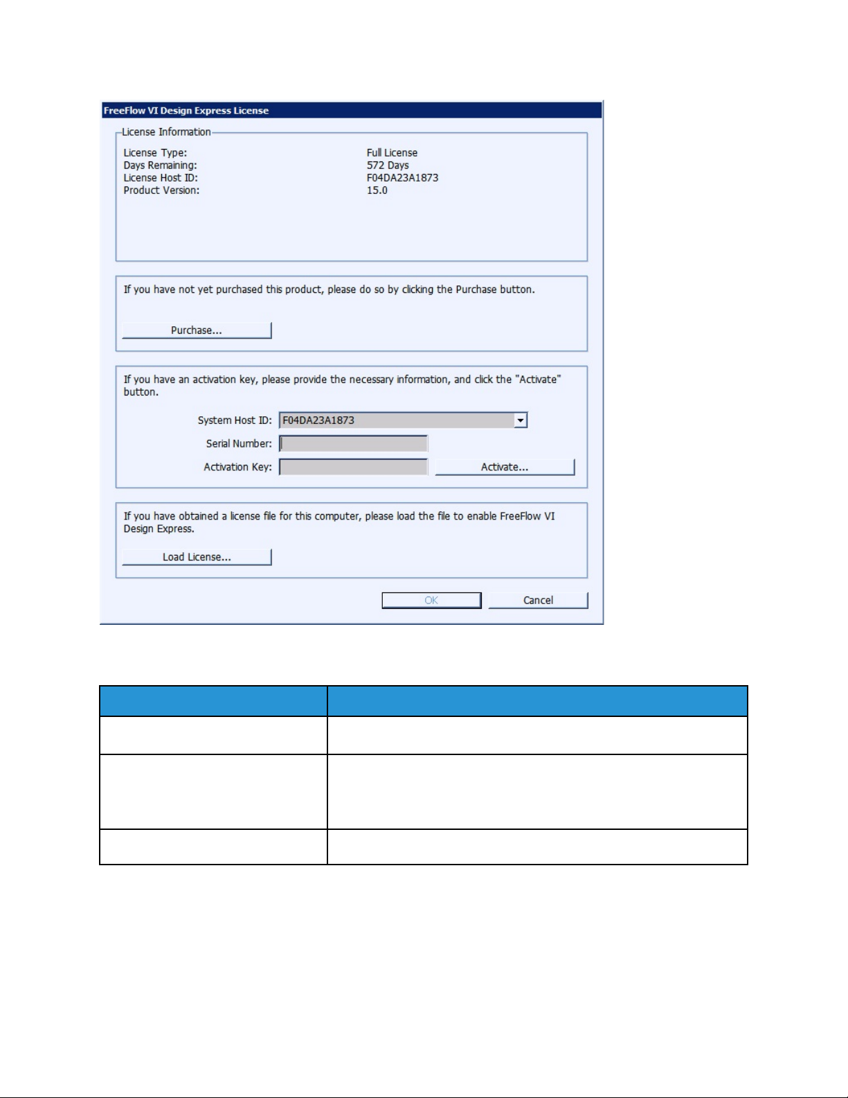
Selecting the Install/Update Software License option will produce the FreeFlow VI Design Pro
License panel. This panel provides access to information about the installed license and two unique
licensing options. Use the panel to choose the option suited to your location.
Xerox
®
FreeFlow®VI Design Pro
User Guide
15
FreeFlow VI Design Pro Installation
License Information
This panel includes:
License Type Description
Days Remaining The number of days until the existing license will expire.
License Host ID VDP finds and displays this information from your computer.
If a valid license file has been loaded, the Host ID used by the license
is shown.
Product Version The installed version of the VDP software.
If you have obtained a license file...
Use this option when you have received a license file (*.dat) (usually via email). When the file is
delivered be sure to store it in a safe and accessible place on your computer.
For further instruction, refer to Using the Load License option.
16
Xerox®FreeFlow®VI Design Pro
User Guide

FreeFlow VI Design Pro Installation
If you have an activation key...
The information in this panel is designed for users who have received a software activation key as part of the software license kit for the VDP software. If you do not have the license kit, and are in a location that requires this option, contact your Xerox sales representative to purchase the software license kit for VI Design Pro software. Once the order has been processed a ship kit containing the Software Activation Key and Serial Number (If provided) will be shipped to the customer location. For further instruction, refer to Using the Activation Key option.
UUssiinngg tthhee LLooaadd LLiicceennssee OOppttiioonn
To activate the VI Design Pro license using a license file:
1. Select the Load License option.
2. Browse to the location of the license file, select it, then click OK.
The license is installed. The new license information appears at the top of the license panel.
3. Select OK to activate the license.
UUssiinngg tthhee AAccttiivvaattiioonn KKeeyy ooppttiioonn
Note: Retain the Software Activation Key and Serial Number, if provided, in a safe location as
they may be required for future upgrades, support, and so on.
If you have the Software Activation key, you can use the automated license process outlined here:
1. Choose one of the available System Host IDs for the license HostID. (The default is
recommended.)
Note: If the automated license process fails you will need to have the System Host ID
string and the Software Activation Key available when you contact the Xerox hotline for
assistance.
2. Enter the Serial Number of the device on which the software is installed.
3. Enter the Software Activation Key in the area provided and click the Activate... button.
4. The Xerox License Server may return a form requesting additional information. Fill in the form as
requested and select OK when done.
5. This information and the Software Activation Key will be submitted to the Xerox License Server.
6. At this point the Xerox License Server should have all the information required to validate the
license request. If additional information is required, a new screen requesting additional
information will be displayed. Fill in the required information and select OK.
7. The Xerox License Server will validate the information and either enable the license or return an
error code if the information supplied does not match our records. If an error code is generated,
report the error code to your local Xerox representative so they can assist you further.
If the information entered is valid, a license file will be generated and loaded to you r system. Details
of the license will be displayed in the License Information area of the License screen. To apply the
license, click the OK button. When the OK button is selected, the license will be applied.
On occasion, the automated license activation may fail. When this happens, contact the Xerox hotline
for assistance. Have the System Host ID of the workstation and the Software Activation Kit supplied
Xerox
®
FreeFlow®VI Design Pro
User Guide
17

FreeFlow VI Design Pro Installation
in the ship kit available. Further assistance may result in a license file being emailed to you.
Note: If you fail to connect to the license server using the method shown above, you can go to
any Internet connected device and login to the portal using this URL: https://www.
xeroxlicensing.xerox.com/activation.
Enter the Activation Key and follow the on screen prompts. You will need to know the System
Host ID of the VDP system. A License file will be emailed to you. Move the license to a safe
location on the VDP system and use the Load License option to install the license.
18
Xerox®FreeFlow®VI Design Pro
User Guide

FreeFlow VI Design Pro Installation
Uninstalling VI Design Pro
Remove VI Design Pro by running the uninstall program. The uninstall program presents a series of
windows that allow complete removal of VI Design Pro or to remove selected files and items.
Note: Selecting Cancel stops the uninstall program without completing the procedure. Run the
uninstall program to fully uninstall VI Design Pro.
Caution: When you have an earlier version of VI Design Pro installed on the system you must
use the uninstall program provided with that version of the software to remove those files.
To run the uninstall program:
1. Log on to the Windows workstation as Administrator or with a User Account with administrator
privileges.
2. Launch VI Design Pro's uninstall program by using one of these methods:
• Select Start→All Programs→Xerox FreeFlow VI Design Pro xx, then right-click Uninstall.
• Use the Add or Remove Programs option on the Control Panel.
• Select Start→Run to access the Run window. Then use Browse, when necessary, verify that
the correct path name and uninstall.exe are listed in the Open field (for example, C:\vide
\uninstall.exe), and click OK.
• Using Windows Explorer, access the vide directory on the workstation, or the alternate
location. Locate and double-click uninstall.exe.
3. When the Uninstall VI Design Pro window appears, select the type of uninstall to perform, then
follow the on-screen instructions to complete the uninstall process.
• Performing an automatic uninstall:
An automatic uninstall, which is the default, removes all VI Design Pro software, files, and
directories. In addition, it will remove VI Design Pro from the Programs Folder (Start Menu).
Select Automatic on the Uninstall VI Design Pro window and then follow the on screen
instructions. When the uninstall process is complete, reboot the workstation.
• Performing a custom uninstall:
A custom uninstall allows you to specify which VI Design Pro directories, application files,
system files or .ini files to remove. Use this option to control which items to delete rather than
allow the uninstall program to operate automatically.
4. Reboot the workstation when the software has removed the selected VI Design Pro files,
directories, and software from the system and restored the selected .ini files.
Xerox
®
FreeFlow®VI Design Pro
User Guide
19

FreeFlow VI Design Pro Installation
Adding PostScript Fonts
Order additional PostScript Type I and Type III fonts from the Xerox Font Library. These fonts can be
used on the printer and with VI Design Pro.
The fonts must be in a PostScript format that is supported by the target printer. In general, Type 1
and 3 PostScript fonts are supported on all PostScript printers.
Note: When VI Design Pro is not installed on the C: drive, replace C: in the following description
with the drive on which VI Design Pro is installed.
To import PFA and PFB type fonts into the VI Design Pro fonts directory, select the File menu on the
top menu bar and one of theses options:
• Import Roman PostScript Fonts
• Import Special PostScript Fonts
Use Import Roman PostScript Fonts for fonts using the Standard Roman (or Latin) Character Set as
defined in Adobe's PostScript Language Reference Manual. This is the option generally used for Latin
Type 1 fonts delivered by font vendors.
Note: Use the Import Roman PostScript Fonts option to install Specialty Imaging fonts.
These fonts are suitable for re-encoding by VIPP
®
, using the default re-encoding table, and can be
referenced in the xgf\encoding\fontlist file.
Use Import Special PostScript Fonts for fonts using any other character set (typically barcode fonts
or fonts converted from other legacy formats).
These fonts must not be re-encoded and must be referenced in the xgf\encoding\nullfl file.
Using either option, one or more fonts can be selected. The fonts will be converted into regular PS
fonts and placed in the C:\vide\fonts directory. Also, as part of the font conversion process, the
file C:\vide\xgf\encoding\fontlist (for roman fonts) or C:\vide\xgf\encoding
\nullfl (for special fonts) will be updated with the newly imported font names. By default, the
®
VIPP
font names are of the incremental form /RFAAxxxx (in fontlist) or /SFAAxxxx (in nullfl) where
xxxx is a number ranging from 0000 to 999999. The resulting fontlist or nullfl file can be edited to
change these names or add font family information (refer to Customization below).
Within VI Design Pro, the font key names cannot be more than 10 characters long, not counting the
backslash (e.g. /RFAA123456), due to current constraints in the GUI menu display width format;
however, this limit should be sufficient for most purposes since VIPP
®
font key names are meant to be
short names used as shortcuts for the long font names.
Important: These fonts are often subject to licensing agreements and must be used in
accordance with the terms of the agreement. You are responsible for checking the licensing
agreement for any fonts and complying with the terms before installation for use with VI
Design Pro.
Once you complete these tasks you will be requested to restart VI Design Pro. Then the new fonts will
appear in the font pull down menus and you could access them in the VIPP
®
code using the VIPP
®
short name.
20
Xerox®FreeFlow®VI Design Pro
User Guide
CCuussttoommiizzaattiioonn
FreeFlow VI Design Pro Installation
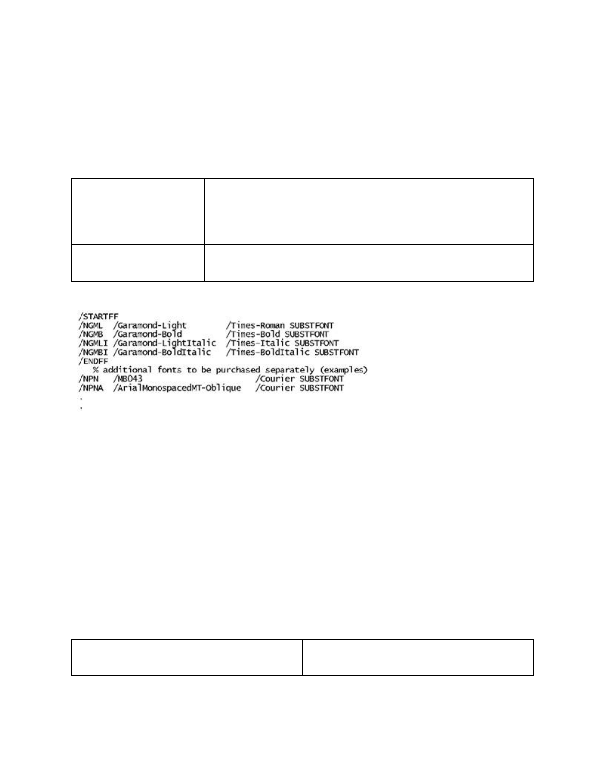
The files, C:\vide\xgf\encoding\fontlist or C:\vide\xgf\encoding\nullfl, can be
edited to change the VIPP
®
font names or to add font family information.
The syntax for each entry in these lists is:
/VIPP_Shortname /PSFontname /substitute_fontname SUBSTFONT
Where:
/VIPP_Shortname
/PSFontname
/substitute_fontname
SUBSTFONT
is a unique user-defined identifier for this font (max 10 characters long).
is the name of the PostScript font as it appears inside the file under the
/FontName key.
(optional) is any font name that will be substituted when the font referenced
by /PSFontname is not available.
This example shows part of the C:\vide\xgf\encoding\fontlist file.
The /STARTFF and /ENDFF markers are optional and can be used to delimit a font family. Refer to the
®
VIPP
Language Reference Manual for more details.
KKeerrnniinngg
Kerning information for a PostScript font is available in an Adobe Font Metrics (AFM) file. AFM files
are generally supplied with the font kit when the font is purchased. Specifications for the AFM file can
be obtained from Adobe, Inc.
Kerning can be enabled for VIPP
• Extended syntax on the entry in the font lists
• SETKERN and INDEXKERN commands
Use this syntax in fontlist to establish the link between a given font and an AFM file:
/VIPP_Shortname [ /PSFontname (AFM_filename) ]
Where:
AFM_filename
The AFM file must be located in one of the libraries referenced by SETMPATH or SETEPATH (or
SETPPATH in project mode).
®
SHx commands using:
This is the name of the AFM file containing kerning
information for the associated font.
Xerox
®
FreeFlow®VI Design Pro
User Guide
21

FreeFlow VI Design Pro Installation
Kerning is disabled by default.
22
Xerox®FreeFlow®VI Design Pro
User Guide

2
Program Overview
This chapter contains:
• VI Suite Customer Forum ........................................................................................................... 25
• Using VI Design Pro ................................................................................................................... 26
• Using Fonts.. ........... ........... ........... ........... ........... ....................................................................... 28
• Job Data and Performance.............. ........... ........... ........... ........... ........... ........... ........... ........... ... 31
• Reconciliation and Graphic Element Restrictions......................................................................... 32
• Crash Recovery.............. ........... ........... ........... ........... ........... ........... ........... ........... ..................... 33
VI Design Pro is a Graphical User Interface (GUI) program, designed to simplify the creation of VIPP
applications. VI Design Pro can be used to create new VIPP®applications, or to view or modify
existing VIPP
capabilities provided by FreeFlow Variable Information Suite (VIS) applications to process data-driven
graphics, data-driven conditional processing, transactional printing, and database publishing.
VI Design Pro can save your application in legacy or VI Project Container format for fast printing to
your VIPP
the power of Dynamic Document Construction. Additionally, you can output your application as a
PDF, using the File menu option Export Job as PDF. For large print volumes of records, this option can
take longer. This option cannot use the full power of Dynamic Document Construction available when
printing the legacy or VI Project Container formats to a VIPP
of the PDF file can be very large, based on the options used to create the PDF file.
Note: The GUI display is rendered using an internal PS engine, and therefore cannot render
correctly PDF files with transparency. PDF files are converted internally to EPS for display
purposes in the GUI. Although the GUI cannot render transparency correctly, if you print to an
FFPS APPE engine, transparency is honored at the device.
In addition to the GUI, VI Design Pro provides the following:
• Application templates
• Smart Editor features to simplify the creation or modification of VIPP
• Full support of the VIPP
• What You See is What You Get (WYSIWYG) representation of the VIPP
The GUI and WYSIWYG provide an interactive environment in which to create the VIPP
applications, and represent how the application prints on the device.
®
applications. VI Design Pro is the only GUI-based product that can use all the
®
-enabled print device or to the VI eCompose system, which converts VIPP®to PDF, using
®
-enabled printer. Additionally, the size
®
applications
®
command set
®
application.
®
®
License required
To use VI Design Pro, a license is required. For more information, refer to FreeFlow VI Design Pro
Installation.
Without the license, the program runs in Demonstration mode for a 60-day period, after which VI
Design Pro exists when it is invoked.
Xerox®FreeFlow®VI Design Pro
User Guide
23

Program Overview
Unsupported software
Operation of the VDP software on a computer with VMWare as the base operating system, and
the use of Remote Desktop or other sharing software, is not tested, and is not supported.
Watermarks
When the program runs in Demonstration mode, the following watermark is produced on every
page of the VIPP
®
job:
Unlicensed FreeFlow VI Design Pro. Please contact a Xerox Sales representative for more details.
24
Xerox®FreeFlow®VI Design Pro
User Guide

Program Overview
VI Suite Customer Forum
Xerox hosts a Community Support Forum. The VI Suite Customer forum is now part of the larger
support forum, allowing you to post and review information about Xerox products and services all
from one location. Take a minute to log in to this customer forum community: http://VIPPsupport.
xerox.com.
Xerox
®
FreeFlow®VI Design Pro
User Guide
25

Program Overview
Using VI Design Pro
To use VI Design Pro you must be familiar with the VIPP®programming language and how VIPP
®
applications are created. If you are not familiar with VIPP®, there are other third-party GUI design
tools that can be used by non-programmers, which provide VIPP
®
design capabilities using a drag-
and-drop interface.
For a review of the basic information about the VIPP
®
program, refer to the following sections of the
FreeFlow Variable Information Suite documentation:
• VIPP
®
and VI Compose Overview: This chapter in the FreeFlow VI Compose User Guide provides
some of the background information needed to understand what is involved in VIPP
®
applications. The chapter contains information about the following subjects:
– VIPP
– VIPP
®
and PostScript
®
-enabled devices
– Repositories
– VI Projects
®
– VIPP
• VIPP
modes in which VIPP
core functionality
®
Data Streams: This chapter in the FreeFlow VI Compose User Guide describes the various
®
applications are used: Native mode, Line mode, Database mode, and XML
mode. Other information in this chapter includes:
– Linking the data with the JDT, DBM, or XJT
– Record structures
– Record structures and the mode and presentation relationship
– Functions
– Conditional processing
– Dynamic boxes
– Data-Driven Graphics (DDG)
• VIPP
®
Resources: This chapter in the FreeFlow VI Compose User Guide describes the files stored in
the VIPP
®
libraries that are used for accessing and processing VIPP®jobs. The chapter includes
information about the different types of resources, the different ways in which VIPP
®
those resources, and the mechanism and syntax used to embed resources in the data stream.
®
VIPP
-supported resource types include:
– VI Project
– VI Compose and setup files
– Fonts
– Forms
– Segments
– Images
– Job Descriptor Tickets
– XML Job Tickets
can access
– Data Base Masters
26
Xerox®FreeFlow®VI Design Pro
User Guide

– Distribution lists
– Text files
• VIPP
®
Commands: This chapter in the VIPP®Language Reference Manual provides detailed
information about each of the VIPP
part of VI Design Pro Help.
Program Overview
®
commands. VIPP®commands are included as a separate
Xerox
®
FreeFlow®VI Design Pro
User Guide
27

Program Overview
Using Fonts
To read a discussion of how to install PostScript fonts and customize fontlist or nullfl, refer to Adding
PostScript fonts. You can edit the files to change the VIPP
information.
®
font names or to add font family
UUssiinngg MMuullttiippllee--BByyttee FFoonnttss
The VIPP®and VI Design Pro software support the use of multiple-byte fonts, including fonts
designed for vertical printing. The term multiple-byte or multi-byte font is used to describe fonts that
require more characters than can be specified in an 8-bit byte. VIPP
Japanese, and Korean (CJK) fonts. For more information about how the SHx commands have been
modified for use with these fonts, refer to the FreeFlow VI Compose User Guide and VIPP
Reference Manual.
To meet the requirements for vertical printing with CJK fonts:
• The command syntax for SHP and SHMF has been extended with selectable options for behaviors
related to Asian languages.
• Encoding and special character lists are defined in the xgf/src/cjk.def file.
• The commands SETCJKENCMAP, SETCJKRULES, SETV2HCONV, and SETV2HTABLE have been
added to the VIPP
• Commands such as FROMLINE, RPEKEY, GETFIELD, SETRCD, SETPCD, and GETINTV have been
adapted to work on character boundaries instead of byte boundaries when a multi-byte font is
selected.
®
programming language.
®
specifications include Chinese,
®
Language
VVeerrttiiccaall WWrriittiinngg
When using vertical multiple-byte fonts with SHx commands, all horizontal behaviors become vertical
behaviors:
• Left alignment becomes top alignment.
• Right alignment becomes bottom alignment.
• Horizontal centering becomes vertical centering.
• Horizontal justification becomes vertical justification.
• Column width becomes column height.
• Line spacing is applied horizontally instead of vertically.
• The secondary horizontal position becomes the secondary vertical position.
• Instead of increasing the vertical print position, the horizontal print position is decreased so that
vertical text is forwarded from right to left.
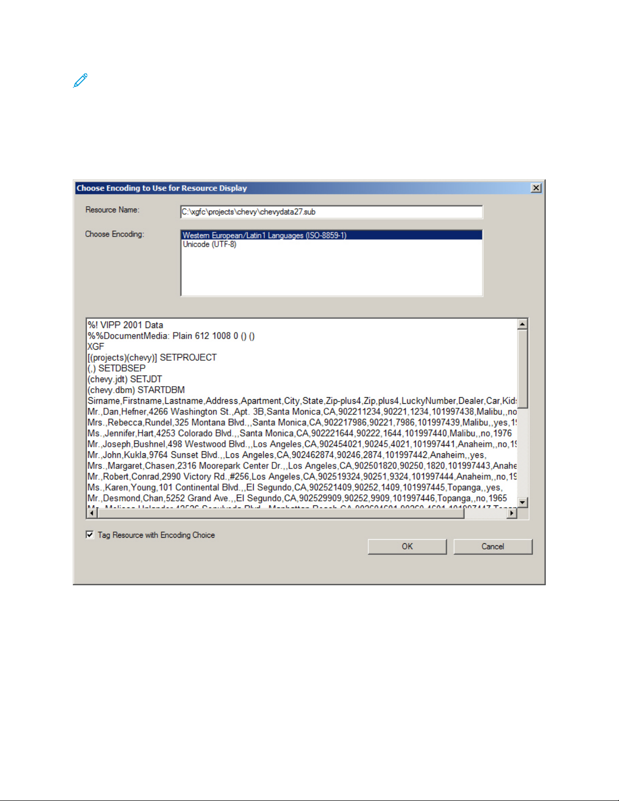
EEnnccooddiinngg MMuullttiippllee--BByyttee FFoonnttss
To change the encoding used by VI Design Pro software to interpret a resource, select Edit→Choose
Resource Encoding, or press Ctrl+E. Select from the available encoding until the multiple-byte text in
the dialog window appears correct.
28
Xerox®FreeFlow®VI Design Pro
User Guide
Program Overview
Note: Invoking the Choose Encoding to Use for Resource Display does not change the
encoding of the resource, only the encoding used for the display.
The dialog is available for use in case VI Design Pro software cannot guess the encoding, or guesses
incorrectly. After the encoding is chosen with the dialog, a tag can be added to the top of the
resource file, so that VI Design Pro can guess correctly next time.
When no tag is present, VI Design Pro looks at the fonts specified in the SETFONT and INDEXFONT
commands and guesses the encoding from the font name.
The encoding options available on this dialog depend upon the settings on the workstation, usually
Control Panel > Regional and Language Options. When no Japanese code page support has been set,
the following options are available:
• Western Europe and Latin Languages, ISO-8859-1
• Unicode UTF-8
When the Japanese code page support has been set, the following options are available:
• Western Europe and Latin Languages, ISO-8859-1
• Unicode UTF-8
®
Xerox
FreeFlow®VI Design Pro
User Guide
29

Program Overview
• Japanese, Shift-JIS
• Japanese, EUC-JP
30
Xerox®FreeFlow®VI Design Pro
User Guide

Program Overview
Job Data and Performance
As a Windows application, VI Design Pro software incorporates both the VI Compose runtime and a
PostScript Interpreter and RIP. In addition, VI Design Pro presents a GUI (Graphical User Interface)
running on a Windows-based workstation, which places certain restrictions on the amount of job data
that can be handled within VI Design Pro. When attempting to load production volumes of job data
into VI Design Pro, unexpected results can occur.
VI Design Pro software is a design tool intended for use during application development. Use VI
Design Pro with just enough line mode or database mode data to verify that the application looks the
way you think it should look, and behaves the way you think it should behave, typically on a few
pages to a maximum of a couple of dozen pages. The performance of VI Design Pro during both
loading and browsing suffers in direct proportion to the amount of job data ingested.
Xerox
®
FreeFlow®VI Design Pro
User Guide
31

Program Overview
Reconciliation and Graphic Element Restrictions
Immediately after invoking VI Compose and the PostScript Interpreter and RIP to render a given
page of your VIPP
®
application, VI Design Pro software taps into VI Compose to get information
about the graphic elements that were rendered to the graphic display. Only those graphic elements
rendered through the use of VIPP
®
marking commands can be accessed for graphic manipulation by
VI Design Pro. Graphic elements rendered through use of raw PostScript are not accessible. VI Design
Pro software performs an analysis of the current state of the VIPP
®
source code in your application,
and references the information against the graphic elements that VI Compose has rendered to the
current page. If a particular rendered element on the graphic display can be matched with a
corresponding fragment of VIPP
®
source code, it is said to have been reconciled with the source
element.
Only reconciled graphic elements can be grabbed, dragged, right-clicked, and so on. To maintain the
integrity of your VIPP
be realized through manipulation of the corresponding VIPP
®
application, any action performed within the graphic display must eventually
®
source code fragment. If a graphic
element cannot be selected with the mouse, then it has not been reconciled.
Because PostScript, and therefore VIPP
®
code can be arbitrarily complex, there are limits to how
effective the analysis portion of the reconciliation activity can be performed. Current limitations in
this area include, but are not restricted to, reconciliation of graphic elements rendered through the
use of conditional execution, loops, or variable substitution. Use of these constructs in your VIPP
®
application source can confuse the reconciliation process, resulting in a failure to reconcile or a
reconcile mismatch. Failure to reconcile or a reconcile mismatch is where a View Source for a
particular element on the graphic display points to an incorrect location in the VIPP
®
source.
32
Xerox®FreeFlow®VI Design Pro
User Guide

Program Overview
Crash Recovery
Upon restart after a crash, VI Design Pro software presents an option to re-instantiate resources from
what was in the resource execution cache when the application terminated abruptly or crashed. The
resource execution cache contains:
• Activities that are performed from the SmartEditor
• WYSIWYG manipulation of graphical elements on the right-side window
• Manual resource edits when the manual edits were sent to VI Compose through an F5 keypress or
toolbar button execution of the resource
Edits that are executed by VI Compose and propagated to the right-side graphical display are saved
in the resource execution cache. Upon restart of VI Design Pro after a crash, if the user chooses,
recovery is attempted, based on the cache contents.
Note that this crash recovery mechanism does not overwrite automatically the original job resources.
After the crash recovery operation completes, it is important to save any changes that were
recovered, just as if you had made a change without an explicit save during a normal editing session.
The usual system prompts to save the changes are presented.
Xerox
®
FreeFlow®VI Design Pro
User Guide
33

Program Overview
34
Xerox®FreeFlow®VI Design Pro
User Guide

3
VI Design Pro GUI
This chapter contains:
• Title, Menu and Tool Bars........................................................................................................... 37
• Input Source Section.................................................................................................................. 60
• Resource Notebook Section........ ................................................................................................ 62
• Debug Session Section ............................................................................. ........... ........... ........... . 68
• Graphical Display Section.......... ........... ........... ........... ........... ..................................................... 70
• Output Resource Section ..... ....................................................................................................... 78
• Status Bar.. ................................................................................................................................ 79
• Edit Modes of Operation ................................................................................................... ......... 80
• Syntax and Formatting Considerations.............................................. ........... ........... ........... ........ 82
• Control and Function Keys.......................................................................................................... 83
• Using the Smart Editor........ ....................................................................................................... 86
• Using the Element Right Mouse Button Menu ................................... ........... ........... ........... ........ 95
• Error Handling................................. ........... ........... ........... ........... ........... .................................... 98
The VI Design Pro window provides GUI tools to create, view, and modify VIPP
Design Pro GUI contains information about how those functions relate to the VI Design Pro program.
Note: The GUI display is rendered using an internal PS engine, and therefore cannot render
correctly PDF files with transparency. PDF files are converted internally to EPS for display
purposes in the GUI. Although the GUI cannot render the transparency correctly, if you print to
an FFPS APPE engine, transparency is honored at the device.
The VI Design Pro window consists of these basic components:
• Title, Menu and Tool Bars
– Title bar
– Activity indicator
– Menu bar
– First tool bar buttons and list boxes
– Second tool bar buttons and list boxes
• Input Source section
• Resource Notebook section
• Graphical Display section
®
applications. The VI
– Graphic display tool bar buttons and list boxes
• Output Resource section
Xerox®FreeFlow®VI Design Pro
User Guide
35

VI Design Pro GUI
• Status bar
Other functions described are:
• Edit modes of operation
• Control and Function keys
• Using the Smart Editor
• Error handling
36
Xerox®FreeFlow®VI Design Pro
User Guide

VI Design Pro GUI
Title, Menu and Tool Bars
The upper most portion of the VDP application consists of components described in these sections:
• Title bar
• Activity indicator
• Menu bar
• Primary Tool bars
TTiittllee BBaarr
The title bar provides this information:
• Product name and version
• Folder name
• Project name
• File name, including path
When a project is open, the title bar provides both the folder and project name, for example: Folder:
xerox/Project: goljob. When working on a single resource, the name of the resource is displayed, for
example: [C:\ xgfc\xerox\goljob\bill.frm].
In addition to the product title, the title bar contains standard Windows buttons th at are used to
control the size of VI Design Pro window on the desktop and to close the program.
AAccttiivviittyy IInnddiiccaattoorr
The activity indicator helps you to determine whether VI Design Pro is still performing the requested
operation. When lengthy VIPP
the gears on the activity indicator turn.
®
is processing such as a long file copy or search operation takes place,
MMeennuu BBaarr
When VI Design Pro window is accessed, the menu bar appears near the top of the window.
The drop-down menus available from the menu bar are:
• File menu
• Edit menu
• View menu
• Debug menu
• Help menu
Xerox
®
FreeFlow®VI Design Pro
User Guide
37

VI Design Pro GUI
FFiillee MMeennuu
The File menu provides these functions:
New
This option allows you to create a new VIPP
Welcome to the VI Design Pro Wizard dialogs display. When the Wizard Classic is clicked, or
when Always Use Wizard Classic was previously enabled on the Welcome to the VI Design Pro
Wizard window, the New VIPP Application window displays.
For detailed information about how to display and use either of these windows, refer to Creating
or modifying applications.
Open
This option allows you to open an existing VIPP
When you access File→Open, the Please choose the file to load window opens, and the Look in
field displays the name of the last directory from which you loaded a file. If this is the first time
after installation that you are loading a file, the Look in field defaults to the VI Design Pro file
folder that was loaded on the system when you installed the VI Design Pro.
For more information about how to use this window, refer to Creating or modifying applications.
Close
This option allows you to close an open VIPP
open application when it is not closed before opening another application or template. You will be
prompted when you do not save the changes to the application.
®
application. When you first select this option, the
®
application.
®
application. VI Design Pro automatically closes the
Save
This option allows you to save the changes made to the current page of the existing VIPP
®
application. For example, when you make changes to the JDT tab and select File→Save, only the
changes you made to the JDT tab are saved. Use File→Save All to save all the changes made to
the VIPP
®
application.
Save As
This option allows you to save the currently active file using a new name. When you select this
option, the Save As window displays, and allow you to specify the directory and file name to use
for the new file.
In general, use File→Save As in VI Design Pro to copy a portion of the current application to a
different file name so that you can use it again with a different application. Using the Save As
tool bar button has no effect on the files that are currently included in the current application.
Save All
This option allows you to save all of the changes that you made to the VIPP
®
application. Use
File→Save to save changes to the current page of the application when you only made changes
to the JDT tab.
Copy Project
This option allows you to copy a VI Project, and to use an existing VI Project as a template for a
new project. When you select File→Copy Project, the Please choose the project to copy window
displays, this window allows you to browse for and select the project you want to copy.
38
Xerox®FreeFlow®VI Design Pro
User Guide

VI Design Pro GUI
Once the project to copy is selected, you will be prompted to enter a new folder and new project
name. If needed, enable the check box to include the original project's history in the new project.
Merge Database Projects
This option allows you to merge database projects. The option provides the means to merge
database files with disparate header names and to rename the database fields or names in the
DBM file.
When you select File→Merge Database Projects, the Merge Database Projects dialog displays.
Use the dialog to browse for, and select the data you want to associate in a VIPP
®
database
project, with the DBM file of another database project.
Xerox
®
FreeFlow®VI Design Pro
User Guide
39

VI Design Pro GUI
When you click on the Browse button next to the Source Database Project or CSV File window, the
Please choose a source database project or CSV file screen is produced. Use the screen browse for and
enter a data source. The data source can be either a VI Project (.vpc or .vpf file) or a CSV file.
After you select the source database project, use the Browse button next to Target Database Project
to open a similar screen from which to browse for and choose the target database.
When both source and target projects have been selected click OK to continue.
When the data source is a CSV file, you will be prompted to specify the field delimiter of the CSV file.
The first line of the CSV file must contain data field names. The data must begin on the second line.
40
Xerox®FreeFlow®VI Design Pro
User Guide

VI Design Pro GUI
After the database files and field delimiter have been defined the Map Database Fields dialog
displays. Map the fields of the data source to the fields in the target project.
The Data File Fields column contains the fields found in the source submission file or CSV file. The
DBM File Fields column contains the fields in the target project. When you select an entry from
these columns, a sample data value will be displayed below the column as an aid in mapping the
source and target fields.
To map fields with the same values, highlight the fields to map and click on the Map button.
When fields are incorrectly mapped, select the appropriate Mapped Fields entry and click on the
Unmap button. The entry is removed from the Mapped Fields column and the appropriate fields are
added to the Data File Fields and DBM File Fields columns.
When mapping is complete, click on the OK button. The following files will be modified:
®
Xerox
FreeFlow®VI Design Pro
User Guide
41

VI Design Pro GUI
• The target project submission file will contain the field names and data from the source project or
CSV file. The SETDBSEP parameter will be modified as necessary.
• The target project DBM file will be modified such that all the original field references (e.g.,
FIELD1) will be replaced with the field names from the new target project submission file (e.g.,
Fname).
The source project files (or source CSV file) will not be modified.
When fields are not mapped, the Project Merge Information dialog will be displayed.
Click OK to confirm, the modified target project will be opened in VI Design Pro.
Create Project
This option allows you to save an existing VIPP
®
application as a VI Project.
Export Project Container
This option allows you to create a compressed archive file from the currently loaded VI Project.
The compressed archive file can then be used for activities such as an email attachment, archiving,
deployment, and so on.
When you select File→Export Project Container, the Please select export destination window
displays, and allow you to specify the file name and destination for the archived file. Once you
specify a directory and file name and select Save, VI Design Pro creates the compressed archive
file. The compressed archive file will have a file extension of .vpc.
Import Roman PostScript Fonts
Import Special PostScript Fonts
These options allow you to import PFA and PFB type fonts into the VI Design Pro fonts directory.
Use Import Roman PostScript Fonts for fonts using the Standard Roman (or Latin) Character Set as
defined in Adobe's PostScript Language Reference Manual. This is the option generally used for
Latin.
Type 1 fonts delivered by font vendors. These fonts are suitable for re-encoding using the default
re-encoding table, and can be referenced in the xgf\encoding\fontlist file.
42
Xerox®FreeFlow®VI Design Pro
User Guide

VI Design Pro GUI
Note: Xerox Specialty Imaging fonts must be imported into VI Design Pro using the Import
Roman Fonts option described above in order for VDP to find the fonts and render them on the
screen. A pattern representing the special effect appears on-screen, as the effect is only
generated on the FFPS when the application is printed.
Use Import Special PostScript Fonts for fonts using any other character set (typically barcode fonts or
fonts converted from other legacy formats). These fonts must not be re-encoded and must be
referenced in the xgf\encoding\nullfl file.
Using either option, one or more fonts can be selected. The fonts will be converted into regular PS
fonts and placed in the C:\vide\fonts directory. Also, as part of the font conversion process, the
file C:\vide\xgf\encoding\fontlist (for roman fonts) or C:\vide\xgf\encoding
\nullfl (for special fonts) will be updated with the newly imported font names. By default, the
®
VIPP
font names are of the incremental form /RFAAxxxx (in fontlist) or /SFAAxxxx (in nullfl) where
xxxx is a number ranging from 0000 to 999999. The resulting fontlist or nullfl file can be edited to
change these names or add font family information.
Within VI Design Pro, the font key names cannot be more than 10 characters long, not counting the
slash (e.g. /RFAA123456), due to current constraints in the GUI menu display width format; however,
this limit should be sufficient for most purposes since VIPP
®
font key names are meant to be short
names used as shortcuts for the long font names.
Important: These fonts are often subject to licensing agreements and must be used in
accordance with the terms of the agreement. You are responsible for checking the licensing
agreement for any fonts and complying with the terms before installation for use with VI
Design Pro.
Proof Print
This option allows you to print a job to verify the printed output. This option is intended for shortrun printing for use in proofing the output of an application. This option can only be used with a
PostScript printer.
Note: VI Design Pro is a design tool that allows you to test subsets of the print job data. Do not
use VI Design Pro to test print jobs that exceed 100 pages. For best results, Xerox recommends
that you limit the size of the subsets to 20 pages.
When you select File→Proof Print, the Proof Print window displays. Use this window to select the
locally attached or network PostScript printer on which to print the application, specify the print
®
Xerox
FreeFlow®VI Design Pro
User Guide
43

VI Design Pro GUI
criteria to use, and select any related resources.
Use the Use Evaluation License box to specify that you are using the VIPP
the job. The default is to leave this box blank. Refer to the VIPP
®
Language Reference Manual or
Help→VIPP Language Reference Manual for more information about VIPP
®
Evaluation license to print
®
evaluation licenses and
how they impact the print jobs.
Use the Page Range boxes to define the range of pages to print. The page range selection in
File→Proof Print refers to logical pages, while the graphic display shows the current and total
physical pages of the application. This means that for Multi-Up applications the Proof Print page
range selection values may not correspond 1-to-1 with the actual number or position of logical pages.
Selec tthe range of pages to be printed based on the desired logical page numbers, not the physical
page numbers.
Use Select resources for an additional printout list box to select resources to include in the job. The list
contains the VIPP
®
application resources associated with the item you have selected to print.
Convert PDF to EPS
Use Convert PDF to EPS to manually convert PDF files to EPS. Select the PDF file(s) to convert. You
will be prompted to supply the target folder for the .eps files.
Modify PDF with Embedded EPS
®
VIPP
PDF file when printing to an APPE engine. When printing to a PostScript engine, VIPP
supports the use of PDF files as variable resources. However, VIPP®can only use the actual
®
needs to
convert the PDF to EPS. The process to embed the PDF file with EPS can be done in one of two
ways:
• In line (using VI Design Pro), when adding PDF files to your project
• In batch mode using the Embed PDF with EPS option.
VI Design Pro will detect any PDF file added to a Project, and if not embedded with EPS, will
embed the EPS information. This process can take a second or two per PDF. You can avoid this task
interrupting your design work by embedding the EPS information in batch mode prior to editing
your job, by using the Modify PDF with Embedded EPS option. To do so, place all PDF files in a
folder, then select the Modify PDF with Embedded EPS option. Next, point to the folder
containing the PDF files and select the PDF file(s) to embed.
Advanced PDF Options
Advanced PDF options such as transparency, are lost when generating the EPS image file, but are
still retained in the PDF file. When printing the PDF to the PS interpreter, VIPP
®
will use the
embedded EPS language.
Do not use this option with the FFPS Adobe Print Engine (APPE)
When you design applications targeting the FFPS APPE that use PDF resources, do not use this
option. APPE can directly ingest the PDF resources in a VIPP
®
application.
Export Job as PDF
To use the Export Job as PDF option, you first have to open the job in VI Design Pro. VI Design Pro's
GUI has been restricted, for performance reasons when developing VIPP
®
applications, to only display
the first 100 records. Although you may not be able to load a large job (greater than 100 records)
fully into VI Design Pro's GUI, when you select the option to Export Job as PDF, VI Design Pro will
print all records, based on the submission data file you selected.
With a job loaded into VI Design Pro, select File→Export Job as PDF. A dialog box will be displayed.
Use the dialog box to specify the name of the PDF file. By default, the system will use the job name,
44
Xerox®FreeFlow®VI Design Pro
User Guide

and the folder to store the PDF file.
VI Design Pro GUI
After specifying the PDF file name, browse to the folder in which you want to store the PDF file, then
select Save to move to the next option screen.
Note: Depending upon the job options used (resolution, etc) and the number of records being
processed, the time taken to create the PDF using the "Export Job as PDF" can take a while
(5000 records may take 3 hours), locking up your workstation for this task. We recommend
using the Export Job as PDF for small record counts and using the VI Project Container (.vpc)
format for larger record counts. The same 5,000 records when exported to a .vpc file takes a
few seconds to save the .vpc file and depending on the print engine, 25 minutes to print on a
Xerox print device enabled with VI Compose.
The Options panel for the Export Job as PDF will be displayed.
These options can be selected:
Xerox
®
FreeFlow®VI Design Pro
User Guide
45

VI Design Pro GUI
PDF Quality Settings Description
High This will generate print quality PDF. Because the PDF file
will be of a higher resolution, it may take longer to
generate the PDF file and the size will be larger than the
other options.
Medium This will generate a PDF of medium print quality. This will
be quicker to produce than the option above and the PDF
file should be smaller in size.
Low Intended for proof or archive & viewing, this will generate
a PDF of low resolution. This will be quicker to produce
than the option above and the PDF file should be smaller
in size.
Custom This option allows you to browse your file system for
Adobe Job Option files, which allow total control of the
options used to generate the PDF file.
View PDF after completion VI Design Pro will generate the PDF file and save to the
location you specified above. If you select View PDF after
completion, VI Design Pro will attempt to open the PDF file
in Adobe Acrobat or Reader. If neither are present on your
PC, then this option will be ignored.
Create Log file This option will generate a log file detailing JobOptions file
used, Output Folder, font information, etc. This option is
recommended only if you need to trouble shoot the PDF
generation. If this option is used, it is up to the user to
manually delete these log files (located in the same folder
as the PDF file).
Use production data for submission (if
available)
Include media and finishing options Select this option to include all of the media and finishing
If a production data file has been added to the project
using the Add Resource to Project option, you can select to
print that production data file by selecting this option. If
this option is unchecked, VI Design Pro will assume no
production data file exists and will use the data file used
during the design of the application.
options that have been defined and enabled for the job in
the finished PDF.
This option is intended for use with FreeFlow Print Server
devices using the Adobe PDF Print Engine (APPE). It will
have no effect on any other printer.
Selecting this option will increase the size of the resulting
PDF, sometimes significantly, depending on the number of
media changes and finishing options defined for the job
and the total number of pages.
The graphic below shows a typical VI Project file. The TestText.dbf file is the test file used during the
design of the application. This is signified by the Printer and Cog wheel icon. The vtpworkshop.dbf file
46
Xerox®FreeFlow®VI Design Pro
User Guide

VI Design Pro GUI
has been added as a production data file, as signified by the Printer and the number "1".
Recent Files
This option displays the last four files that you loaded on VI Design Pro. Use File→Recent Files to
select and reload one of the listed files.
Exit
This option allows you to exit VI Design Pro. When there are unsaved changes in an open VIPP
®
application you will be prompted to save them.
NNootteess AAbboouutt EExxppoorrttiinngg aa JJoobb aass aa PPDDFF
VI Design Pro can export the VIPP®application to a PDF file in a location you specify on your file
system. Additionally, if the option is checked, it will open the PDF in Acrobat Reader for viewing
purposes. Other options can be checked to enable a log file or to specify the sample or production
data file.
Efficiency
Exporting to a PDF is not as efficient as outputting to VIPP
Caveats when exporting a PDF file:
Unpredictable results will occur if using Xerox Specialty imaging and exporting to PDF. Xerox
Specialty Imaging effects are not supported when exporting to PDF.
Plex changes within a job are not supported unless you are printing to an FFPS APPE engine
supporting PDF/VT.
Feeding and finishing options selected within a job may not be supported unless you are printing
to an FFPS APPE engine supporting PDF/VT.
The table shown below is a comparison of printing jobs containing 50, 100, 500, 1000, 3000 and
5000 records, to exporting the same files using the PDF option. Included in the comparison is the
time to generate the files (.vpc and PDF) and print those files on the same Printer, and a
comparison of the file size based on the record count.
• The application used for the performance test below is a 4 up Post Card application printed
duplex on a 12’ x 18’ sheet.
®
legacy or VI Project formats.
Xerox
®
FreeFlow®VI Design Pro
User Guide
47

VI Design Pro GUI
• The PDF output was generated using the Standard-USLetter.joboptions file.
• The target print device was an FFPS XC1000.
PDF
Number of
Records VPC Size
VPC
Process and
Print Time
(in seconds)
Creation
and Print
1
Time
(in
seconds)
PDF Size
PDF
Creation
Time (in
seconds)
VPC Time
Savings
2
(in seconds)
100 129mb 57 66 1.35mb 7 9
500 129mb 152 331 3.84mb 26 179
1000 129mb 736 1,366 6.39mb 46 630
3000 129mb 887 4,151 17.3mb 131 3,264
5000 129mb 1,446 6,932 27.5mb 212 5,486
Note: Times will vary based on the sheet size, the complexity of the application, the type of
image, and conditional logic applied. The chart above should be used as a guide only. For more
accurate information perform the same type of test on your own equipment.
Based on the results shown in the chart above, there are obvious benefits to using VI Compose
on a Xerox print device when printing large volumes of records. If not already enabled, contact
your local sales representative to purchase VI Compose for your print device.
Note: When VI Design Pro is generating the PDF file, the workstation should not be used for
other purposes. Using the workstation for other purposes will greatly affect the time.
1. Includes PDF creation time on Workstation.
2. VPC Time Savings is the difference in time when using a .vpc and VI Compose (on the Printer). Based on the
information presented in this chart, there are substantial performance benefits to using VI Compose on the target
print device and the vpc output from VI Design Pro when dealing with large record volumes.
48
Xerox®FreeFlow®VI Design Pro
User Guide

VI Design Pro GUI
EEddiitt MMeennuu
The Edit menu provides these editing functions:
Undo
This option allows you to reverse the most recent text change, deletion, or addition you made on
the Input Source or Resource Notebook section of VI Design Pro's window.
Redo
This option allows you to reverse the preceding Undo operation.
Cut
This option allows you to remove selected text in the Input Source or Resource Notebook section,
or to remove a selected object in the Graphical Display section. Text or objects removed by
Edit→Cut are stored on the Clipboard.
Copy
This option allows you to copy selected text in the Input Source or Resource Notebook section, or
to copy a selected object in the Graphical Display section. Text or objects copied by Edit→Copy
are stored on the Clipboard.
Paste
This option allows you to paste the contents of the Clipboard at the current cursor position in the
Input Source, Resource Notebook, or Graphical Display section.
Select All
This option allows you to select all of the text in the area in which the cursor is currently
positioned. Cursor position and related options are described here:
Input Source section
Resource Notebook section
all text in that section will be selected
all text for the file displayed for the resource listed
under the current tab will be selected. To select the
text for more than one tab in the Resource Notebook
section, you must access each tab separately and
then choose Edit→Select All again.
Selected text is highlighted with a dark blue background. Once the text is selected, a cut or copy
operation can be performed.
Find
This option allows you to search either the Input Source section or the currently tabbed resource in
the Resource Notebook section for the first occurrence of a text string. Narrow the search criteria
by enabling the Match whole word only or Match case fields.
Once you select Edit→Find, VI Design Pro locates the specified string. When a matching string is
found, VI Design Pro highlights the found string.
Find In Project
This option allows you to search an entire project for all occurrences of a particular text string.
When you select this option, the Find In Project window displays. Narrow the search criteria by
enabling the Match whole word only or Match case fields. Refer to Output Resource section for
more information.
®
Xerox
FreeFlow®VI Design Pro
User Guide
49

VI Design Pro GUI
Replace
This option allows you to search either the Input Source section or the currently tabbed resource in
the Resource Notebook section for each occurrence of a text string and replace the string with
another string. The search begins following the current cursor position.
Use Find what in this window to identify the string to locate and replace. Narrow the search
criteria by enabling the Match whole word only or Match case fields.
Use Replace with to specify the string with which to replace the found text. To selectively replace
the found strings, use Find Next and Replace. Use Replace All to make global changes.
Choose Resource Encoding...
This option invokes the Choose Encoding to Use for Resource Display dialog. Refer to Encoding
multi-byte fonts for more information.
Mark text as Comments
This Ctrl+Alt+C allows you to add the % that marks a comment to the beginning of each line in a
block of selected text.
Unmark commented text
This Ctrl+Alt+U allows you to remove the % from the beginning of each line of selected text. Any
lines in the selected block of text that do not begin with a % will be ignored.
VViieeww MMeennuu
The View menu provides the capability to display these views in VI Design Pro window:
Note: If no view options are selected, VI Design Pro window displays only the graphical
representation of the current page.
Source
This option performs the same task as the View Source button on the first tool bar.
When you enable View→Source variable data, the resource notebook containing the source code
for the resources, and the graphical representation of the current page are displayed. Resize the
windows and edit the contents in this mode.
Hexadecimal
This option performs the same task as the View Hexadecimal button on the first tool bar.
When you enable View→Hexadecimal, the variable data, the resource notebook containing the
source code for the resources, and a graphic representation of the variable data or resource
selected in hexadecimal format are displayed. The windows can be resized, however, you will not
be able to edit the contents.
The next time you select the option which removes the checkmark, the graphical representation in
the Graphical Display section returns to its original state.
Note: The Hexadecimal option cannot be selected unless the Source option is already
enabled.
Output
This option allows you to display the results of the most recent Find in Project operation. The
section windows can be resized and the contents edited. This option performs the same task as the
View Output button on the first tool bar.
50
Xerox®FreeFlow®VI Design Pro
User Guide

VI Design Pro GUI
Full Screen
This option allows you to display a graphical representation of the current page in full screen
mode, the same task as the Full Screen button on the first tool bar.
To disable full screen mode and return to the original view, select the End Full-Screen Mode
button located at the end of the top tool bar.
DDeebbuugg MMeennuu
The Debug menu provides access to start, stop and reset a debug session, as well as a way to inspect
breakpoints and run to and step past a set breakpoint. The menu consists of these options:
Insert/Remove Breakpoint
This option inserts or removes a breakpoint at the line of the current cursor location of the active
text resource, the same task as the Insert/Remove Breakpoint button on the first tool bar. This
option can only be selected when there is no active debug session in progress. A set breakpoint is
indicated by a red stop sign indicator on the left edge of the text resource.
View Breakpoints
This option displays a list of the currently set breakpoints by filename and line number, the same
task as the View Breakpoints button on the first tool bar. This option can only be selected when
there is no active debug session in progress. You can browse through the currently set breakpoints
by double-clicking the left mouse button on a breakpoint in the list, which will set a small green
search marker at the selected breakpoint. Once you have selected the desired breakpoint, you can
close the breakpoint list and, if desired, use the Insert/Remove Breakpoint menu option to remove
the breakpoint.
Start/Stop Debug Session
This option is used to begin or end a debug session, the same task as the Start/Stop Debug
Session button on the first tool bar. This option can only be selected when there are one or more
breakpoints set. During a debug session, most of the rest of the user interface including the
Resource Notebook tabs and Graphical Display buttons, is disabled, this is done to prevent
operations that would disrupt debug operations. Details about running a debug session and
recommendations are discussed in more detail in its own Debug Session section.
Run to Next Breakpoint
This option is used to execute the current page of the loaded job until the next breakpoint is hit,
the same task as the Run to Next Breakpoint button on the first tool bar. This option can only be
selected during a debug session. If a breakpoint is hit a yellow arrow marker, also referred to as the
program counter, will indicate the location of the breakpoint on the line which was just executed.
If there are no more breakpoints encountered the debug session will display the current page of
the loaded job and the debug session will automatically end.
Step to Next Line
This option is used to step from the most recent executed line to the next, the same task as the
Step to Next Line button on the first tool bar. The next line may or may not be the next physical
line of the text resource depending on the logical conditions or other operations that are
determined by the contents of the text resource. The yellow arrow marker (program counter) will
relocate to indicate the location of the line which was just executed. If there are no more lines left
to execute for the current page of the loaded job the debug session will display the current page
of the loaded job and the debug session will automatically end.
Xerox
®
FreeFlow®VI Design Pro
User Guide
51

VI Design Pro GUI
Reset Debug Session
This option is used to reset the current debug session, the same task as the Reset Debug Session
button on the first tool bar. When this option is selected the internal history of which breakpoints
have been hit and the location of the program counter are both wiped clean, just as if the debug
session had been started fresh. This option is useful if the user accidentally steps past a point of
execution and wishes to run or step to that location again without having to stop the debug
session entirely and restart it again.
HHeellpp MMeennuu
The Help menu provides access to the online help for VI Design Pro and VIPP®, as well as version and
copyright information about VI Design Pro. The menu consists of these options:
VI Design Pro Help
This option accesses the VI Design Pro Online Help. Use the Contents, Index and Search tabs to
locate help information.
®
VIPP
Language Reference Manual
This option accesses the VIPP
Index, Search, and Favorite tabs to locate the related help topics, for example, VIPP
information.
®
Language Reference Manual Online Help facility. Use the Contents,
®
command
Install/Update Software License
This option allows you to identify the name and location of a valid license file to VI Design Pro.
Some of the conditions under which you would use this option include:
• A valid license file was not available at the time of installation
• The current license is about to expire or has expired
• To convert from the demonstration version of VI Design Pro to the fully licensed software
version.
When you select this option, the Please select the license file window appears. Use this window to
select the directory and name of the file that contains the valid license information. Once the
appropriate file name appears in the File name field, select Open.
When the License Update Requires Restart window appears, select OK to install or update the
license file.
About VI Design Pro
This option provides copyright and version information for the VI Design Pro application.
PPrriimmaarryy TTooooll bbaarrss
The tool bars in the upper most section of the VDP application window consist of:
• First Tool Bar Buttons and List Boxes
• Second Tool Bar Buttons and List Boxes
FFiirrsstt TTooooll BBaarr BBuuttttoonnss aanndd LLiisstt BBooxxeess
Use the buttons on the first tool bar of VI Design Pro window to perform numerous tasks relating to
file operations.
52
Xerox®FreeFlow®VI Design Pro
User Guide

VI Design Pro GUI
This section describes the function of each button or list box available on the first tool bar, in order,
beginning at the left-most button.
Note: Windows ToolTips are enabled on each button and list box found on all VI Design Pro
tool bars. The pop-up information allows you to quickly identify each of the available functions.
New VIPP
This button allows you to create a new VIPP
®
Application
®
application. When you select this button, either the
VI Design Pro Wizard window or the New VIPP Application window appears.
The window that appears depends on whether the Always Use Wizard Classic box is enabled on
the VI Design Pro Wizard window. For detailed information about how to display and use either
of these windows, refer to Creating or modifying applications.
Open VIPP
This button allows you to open an existing VIPP
®
Application or Project
®
application. When you open an existing VIPP
application, you can view the application information, modify the existing information, execute
the application, and so on.
When you select this button, the Please choose the file to load window appears. Use this window
to select an existing VIPP
®
application. When you first access this window, the Look in field view
shows the name of the last directory from which you loaded a file. If this is the first time after
installation that you are loading a file, the Look in field view defaults to the VI Design Pro file
folder that was loaded on the system when you installed VI Design Pro.
For more information, refer to Creating or modifying applications.
Save file
This button allows you to save the changes you made to the current page of the existing VIPP
application. For example, when you make changes to the JDT tab and click this button, only the
changes you made to the JDT tab are saved. To save all changes that you have made to the VIPP
application, use Save all files.
®
®
®
Save all files
This button allows you to save all of the changes that you made to the VIPP
®
application. If you
only want to save the changes you made to the current page of the application, for example,
when you only made changes to the JDT tab, use the Save file button instead.
Create VI Project from currently loaded application
If you have an application that was created with an earlier release of VIPP
®
and want to create a
Project for that application, use this button . Using this button allows you to create a Project
directory for the application, copy the associated resources from their previous location to the
Project directory, and create a VI Project File. A VI Project file has a file extension of vpf. After the
.vpf file is created, VI Design Pro automatically loads the new file into VI Design Pro window.
Export VI Project Container
This button allows you to create a compressed archive file from the currently loaded VI Project.
The compressed archive file can be used for activities such as an email attachment, archiving,
deployment, and so on.
When you select this option, the Please select export destination window allows you to specify
the directory and file name to use for the archive file to be created. When you specify a directory
and file name and select Save, VI Design Pro creates the compressed archive file. The compressed
archive file has a file extension of vpc.
®
Xerox
FreeFlow®VI Design Pro
User Guide
53

VI Design Pro GUI
Cut (Ctrl+X)
This button allows you to remove selected text from the Input Source or Resource Notebook
section, or remove a selected object from the Graphical Display section. Removed text or objects
are stored on the Clipboard.
Copy (Ctrl+C)
This button allows you to copy selected text in the Input Source or Resource Notebook section, or
copy a selected object in the Graphical Display section. Copied text or objects are stored on the
Clipboard.
Paste (Ctrl+V)
This button allows you to paste the contents of the Clipboard at the current cursor position in the
Input Source, Resource Notebook, or Graphical Display section. The paste operation does not
erase the Clipboard.
Find in Project
This button allows you to search a project for all occurrences of a particular text string. When you
select this button, the Find In Project window displays. Use this window to identify the string to
locate. This option is the same as the Edit→Find in Project option.
Undo
This button allows you to reverse the text change you just made to the Input Source or Resource
Notebook section of VI Design Pro window. Use this button to undo the most recent text change,
deletion, or addition that you made to the VIPP
®
application. This option is the same as the
Edit→Undo option.
Redo
This button allows you to reverse the Undo operation you just made to the Input Source or
Resource Notebook section of VI Design Pro window. This option is the same as the Edit→Redo
option.
View Source
This button displays the variable data, the resource notebook containing the source code for the
resources, and the graphical representation of the current page. The windows can be resized and
the contents edited in Source mode.
View Hexadecimal
This button displays the resource notebook containing the source code for the resources, and a
graphical representation in hexadecimal format. The windows can be resized, however, the
contents cannot be edited.
Note: The View Hexadecimal button cannot be selected unless the View Source option is
already enabled or the View Source button is toggled to display the source code and graphical
representation of the current page.
View Output
This button allows you to display the results of the most recent Find in Project operation. The
section windows can be resized and the contents edited.
54
Xerox®FreeFlow®VI Design Pro
User Guide

VI Design Pro GUI
Full Screen
This button displays a graphical representation of the current page in full screen mode. In full
screen mode, only the top and bottom tool bars of the Graphical Display section appear in the
window.
To disable full screen mode and return to the original view, select the End Full-Screen Mode
button.
Insert/Remove Breakpoint
This option inserts or removes a breakpoint at the line of the current cursor location of the active
text resource. This option can only be selected when there is no active debug session in progress. A
set breakpoint is indicated by a red stop sign indicator on the left edge of the text resource.
View Breakpoints
This option displays a list of the currently set breakpoints by file name and line number. This
option can only be selected when there is no active debug session in progress. You can browse
through the currently set breakpoints by double-clicking the left mouse button on a breakpoint in
the list, which sets a small green search marker at the selected breakpoint. Once you have selected
the desired breakpoint, you can close the breakpoint list and, if desired, use the Insert/Remove
Breakpoint menu option to remove the breakpoint.
Start/Stop Debug Session
This option is used to begin or end a debug session. This option can only be selected when there
are one or more breakpoints set. During a debug session most of the rest of the user interface
including the Resource Notebook tabs and Graphical Display buttons is disabled, this is done to
prevent operations that would disrupt debug operations. Details about running a debug session
and recommendations are discussed in more detail in its own Debug Session section.
Run to Next Breakpoint
This option is used to execute the current page of the loaded job until the next breakpoint is hit.
This option can only be selected during a debug session. If a breakpoint is hit a yellow arrow
marker, often referred to as the program counter, indicates the location of the breakpoint on the
line which was just executed. If there are no more breakpoints encountered the debug session
displays the current page of the loaded job and the debug session will automatically end.
Step to Next Line
This option is used to step from the most recent executed line to the next. The next line may or
may not be the next physical line of the text resource depending on the logical conditions or other
operations that are determined by the contents of the text resource. The yellow arrow marker or
program counter, relocates to indicate the location of the line that was just executed. If there are
no more lines left to execute for the current page of the loaded job, the debug session displays the
current page of the loaded job and automatically ends.
Reset Debug Session
This option is used to reset the current debug session. When this option is selected the internal
history of which breakpoints have been hit and the location of the program counter are both
wiped clean, just as if the debug session had been started fresh. This option is useful if the user
accidentally steps past a point of execution and wishes to run or step to that location again
without having to stop the debug session entirely and restart it again.
Refresh current page of application
This button allows you to execute the current page of the VIPP
®
application along with any
Xerox
®
FreeFlow®VI Design Pro
User Guide
55

VI Design Pro GUI
variable data associated with the page. The current page appears at the bottom of the Graphic
Display section.
Note: Pressing the Refresh current page of application button is not equivalent to
resubmitting the job to a printer. In VI Design Pro, the memory is not reset when you press
Refresh current page of application and the Ghostscript interpreter continues to run without
update for optimization purposes. Only pressing Reset VIPP then Refresh current page of
application, in that order, runs a new instantiation of the Ghostscript interpreter. Refer to Reset
VIPP.
Refresh currently active text resource
This button allows you to execute the currently selected resource. Use this button, or F5, to
redisplay the information for the current resource showing any changes that you have made.
Drop target for Graphic Editing tools
This box displays the name of the resource into which VIPP
®
commands are inserted when the
insert buttons found on the vertical tool bar in the Graphic Display section are used.
When you have cleared the View Source check box, the drop target box is the only way to select
individual resources for viewing.
View PostScript Segment Anchors
This button allows you to display PostScript segment anchors. If you select this button, the graphic
shown on the button appears in the Graphical Display section to indicate each position at which
a PostScript segment anchor exists.
In general, segments are fragments of VIPP
®
or PostScript code that are placed on a page. Each
placement of a segment that consists of only PostScript code is noted with an icon in the
Graphical Display section of VI Design Pro window when you enable the View PostScript
Segment Anchors button.
To place a segment in the desired position on the page use the drag and drop feature to move the
anchor. When you move a segment anchor, the new position is updated in the code for the
application. Segments that contain VIPP
®
code have bounding boxes and are not represented by
a segment icon.
Reset VIPP
®
This button resets VI Compose. This option may be required if you accidentally introduce a VIPP
or PostScript error when manually editing a VIPP®resource.
Use this button with Refresh current page of application to run a new instantiation of the
Ghostscript interpreter when you have made changes to VIPP
®
configuration files xgf/src or
xgf/encoding.
Note: The only method to reset memory and run a new instantiation of the Ghostscript
interpreter is to press Reset VIPP then Refresh current page of the application, in that order.
Proof Print
This button allows you to print a job to verify the printed output. This option is intended for short
run printing for use in proofing the output of an application. Only use this option with a PostScript
printer. This option is the same as the File→Proof Print option.
Help
This button performs the same task as the Help→VI Design Pro Help option. Use the Contents,
Index, and Search tabs to locate help information. You also can access the VIPP
®
Language
Reference Manual online help information.
56
Xerox®FreeFlow®VI Design Pro
User Guide
®

VI Design Pro GUI
SSeeccoonndd TTooooll BBaarr BBuuttttoonnss aanndd LLiisstt BBooxxeess
Use the buttons and list boxes on the second tool bar of VI Design Pro window to select the font and
color options to be applied when performing operations in Graphic Editing mode.
This section describes the function of each button or list box, in order, beginning at the left most list
box.
Font
This box allows you to select the font to use. This list includes all fonts that are currently available.
Font Size
This box allows you to select, or manually enter, the size of the font to use.
Font Foreground Color (Colorkey)
This box allows you to select the name of the text Colorkey to use. The box on the left side of the
box displays the color that you selected. This list includes all of the font Colorkeys that are
currently available for use.
Active Font Background Color (BATKey)
This box allows you to select the name of the background attribute key to assign to the
background attribute key index. The box on the left side of the box displays the background that
you selected. This list includes all of the background attribute keys that are currently available for
use.
Underline
This button allows you to underline subsequently inserted text. After selecting this button, use
Insert Text, or Insert Paragraph on the vertical tool bar in the Graphic Display section.
Font and Effects Preview/Select/Sample
This button allows you to preview fonts, GEPKey and BATKey effects. It also allows you to change
the text displayed in the Font Sample boxes found in many VDP dialogs.
Xerox
®
FreeFlow®VI Design Pro
User Guide
57

VI Design Pro GUI
To change the sample text viewed in the Sample Font window on some Wizard screens, and the
Index Font and Set Font Command dialogs, enter the desired text in the Sample Text box, then
58
Xerox®FreeFlow®VI Design Pro
User Guide

VI Design Pro GUI
select any of the defined effects and click OK.
Graphic Element Property
This box allows you to select the Graphic Element Property (GEP) key to use. The box on the left
side of the box displays the color that you selected. The list includes all of the GEP keys currently
available for use.
Xerox
®
FreeFlow®VI Design Pro
User Guide
59

VI Design Pro GUI
Input Source Section
To display the Input Source section on VI Design Pro window, View→Source or the View Source
button on the first tool bar must be enabled.
Once you open an existing VI Project or VIPP
Input Source section contains the input data for the project or application. This data can be real data
that was created and obtained from an external application, or it can be sample data that was
created while using VI Design Pro to test the output.
Use the Input Source section to modify the data for an existing VI Project or application, or to enter
the data needed when creating a new VI Project or application. You enter data in either of these
ways:
®
file, or create a new VI Project using a template, the
Text Editor mode Place the cursor in the correct position in the section
and enter the changes.
Smart Editor mode Place the cursor in this section and right-click to
display the right mouse button menu.
Key Strokes and Mouse Clicks
When the code for your job is visible on the VDP GUI, you have options for marking or highlighting
sections of that code:
• Use Ctrl+Alt+C, and Ctrl+Alt+U to add or remove a % (comment indicator) from the beginning of
the line in which your cursor is positioned.
• Use your mouse to click one character inside a beginning brace, or an IF/ENDIF, or CASE/
ENDCASE command keyword, to highlight the section of code encapsulated by that brace or
keyword.
60
Xerox®FreeFlow®VI Design Pro
User Guide

VI Design Pro GUI
Xerox®FreeFlow®VI Design Pro
User Guide
61

VI Design Pro GUI
Resource Notebook Section
To display the Resource Notebook section on VI Design Pro window, the View→Source option or
the View Source button on the first tool bar must be enabled.
Once you open a VIPP
are displayed in the Resource Notebook section. The code for each resource can be displayed using
the tabs that are produced across the top of the Resource Notebook section. If the application you
open or create is a VI Project a Project tab and window will also be produced. The information for a
project includes VI Project attributes, resources, and the project's history.
If the number of tabs exceeds the tab space available at the top of this section, a horizontal scroll bar
will appear to allow you to access the remaining tabs.
Use the tabs or click on a resource to view or make changes to the files or resources. Any changes you
make are updated in the code and display in the Graphical Display section of VI Design Pro window
once you press F5 or the Refresh currently active text resource button. This functionality is equivalent
to printing the changes on the printer to verify how they affect the output of the application.
The Resource Notebook section contains the following types of tabs:
• Project Tab
• JDT Tabs
®
application, file, or VI Project, the resources associated with the application
• DBM Tabs
• Segment Tabs
• Form Tabs
• Image Tab
• XJT Tabs
Refer to Creating or Modifying Applications for more information.
PPrroojjeecctt TTaabb
When you open or create a VI Project with VI Design Pro, the Resource Notebook section of VI
Design Pro window displays a Project tab. The Project tab contains information identifying the
attributes, resources, and history associated with the project. Use this tab to make changes to the
application using left mouse functions, or to display the contents or attributes of a specific resource.
62
Xerox®FreeFlow®VI Design Pro
User Guide

VI Design Pro GUI
Note: Existing VIPP®applications that have not been saved as a VI Project will not display this
tab.
The Resource Notebook Project tab is divided into three main sections:
Name of the Section
Attributes the project name, title, author, creation date, copyright information, a brief
Resources the files and folders used by the project. Resources are contained in three nodes
History The actions included in project history are additions and deletions of resources,
Description
description of the project, and the version number and keywords associated with
the project.
named: Local, Folder-shared, and Global-shared.
resource movement from one scope to another, and resource modification. When a
project is saved the accumulated actions taken during the session become
modification entries in the project history. Each modification entry is tagged with
the user name and the date and time of the modification.
Xerox®FreeFlow®VI Design Pro
User Guide
63

VI Design Pro GUI
MMoouussee FFuunnccttiioonnss iinn tthhee PPrroojjeecctt TTaabb
Use these mouse functions to make changes to the project within the Project tab:
• Drag and drop; dragging resources between folders will cause the corresponding resource files to
be moved at the file system level.
The resources that appear within the Resource Notebook window may be reordered within a
folder by using the mouse to drag and release them. The insertion point is immediately below the
drop target. The resource may be moved to the first position in the folder by dropping it on its
parent folder.
Change the order of the submission files (displayed in the Local node) by using the mouse to drag
and drop a new position in the submission order. The entire submission file list will be re-ordered.
• Point and click to select a resource. This action executes either the resource or the print file, as
appropriate.
• Right-click any resource to produce a right mouse button menu. The pop-up menu will contain
commands that can be invoked for the selected resource. Depending upon the type of resource
selected, the following commands can appear:
Properties Allows you to enter text describing the resource.
The entered text will appear after the resource
name on the Project tab.
Launch Associated Application Allows you to launch a Windows application
associated with the selected resource. For example,
if you use a third party graphic editing program,
right-click an image resource in the project, then
select this option to launch the graphic editor.
Add Resource to Project Allows you to add a new resource to a project.
Remove Resource from Project Allows you to remove the resource from the project.
• Double-click a resource to cause VI Design Pro to display the resource text in VI Design Pro
window, or to open the notebook tab.
• Click the left or right Home button, found at the lower left corner of VI Design Pro window, to
display the first or last tab in the Notebook display.
• When multiple graphics are placed in the same area so that they overlap, they are layered. In
many graphic applications the order of the layers can be manipulated by sending a layer to the
®
back, or by bringing a layer to the front. However, with VIPP
source line appears in the VIPP
®
Resource Notebook.
, the order is a function of where the
Therefore, rather than reordering layers to select a specific layer, use the Shift/Left-click combination
to select and deselect specific layers until you access the desired layer. In addition, use the rubber
band group select functionality and then deselect until you access the desired layer.
KKeeyybbooaarrdd FFuunnccttiioonnss iinn TThhee PPrroojjeecctt TTaabb
Use these keyboard functions to make changes on the Project tab:
64
Xerox®FreeFlow®VI Design Pro
User Guide

VI Design Pro GUI
• Use the Up and Down arrows to select or execute resources in sequence.
• Delete resources using Delete.
• Add a resource to a project using Insert once any node of the Project tree has been selected. If
the currently selected node is a resource, a new resource will be inserted immediately below the
selected node. If the currently selected node is the Local, Folder-shared, or Global-shared node the
new resource will be inserted as the first resource under the node. When any other node is
selected the user will be prompted for the target scope of the resource then the resource will be
added in the first position in the selected node.
• The position of a selected resource can be changed by using Shift in combination with the up or
down arrow key.
Change the order of the submission files (displayed in the Local node) by using Shift in
combination with the up or down arrow key. Moving a file to a new position in the submission
order causes the entire submission file list to be re-ordered.
Note: No more than one node of the Project tree may be selected or manipulated at one time
as conflicts may occur.
PPrroojjeecctt TTaabb IIccoonnss
Several kinds of icons are displayed in the Project tab area of the Resource Notebook window. The
icons are graphic representations of the resources' type, submission order, and the active state of
each icon.
• Resource type icons
The left-most icon indicates the type of resource listed. Unique icons are produced for each of the
following resource types:
• forms
• images
• segments
• text, data, and program files
• PostScript files
• submission files
• Submission order icons
The names of submission files appear in the Local node of the Resource section of the Project tab.
These files are accompanied by small printer icons superimposed with a number between 1 and 9,
or by a for numbers greater than 9. The number 0 is reserved for the PrintFile and VI Design Pro.
The PrintFile is displayed as a small printer icon with a gear alongside.
Submission files always appear in their submission order. Submission file order can be changed by
shifting a submission file in relation to other submission files using the mouse to drag and drop
the file, or by selecting the file then using Shift in conjunction with the up or down arrow key to
move it.
• Resource state icons
The icons found to the immediate right of the resource type icon reflect the active state of each
of the listed resources.
®
Xerox
FreeFlow®VI Design Pro
User Guide
65

VI Design Pro GUI
• An outlined checkmark appears when the resource has been referenced or executed at least
once.
• A solid checkmark indicates that the file has been referenced or executed in the context of the
most recently executed resource.
The absence of an icon indicates that the resource has not yet been referenced or executed by the
®
VIPP
interpreter in the context of the current project.
JJDDTT TTaabbss
When you open or create a line mode application with VI Design Pro, the Resource Notebook section
of VI Design Pro window section displays the .jdt tab, which contains the Job Descriptor Ticket (JDT)
information for the application. Use this tab to make changes to the application using the right
mouse button menu. Refer to Creating or modifying applications for further information.
When you select the JDT tab, the Graphical Display section of VI Design Pro window displays and
processes the entire application, including the application data, segments, forms and other resources,
as well as any instructions included in the JDT.
DDBBMM TTaabbss
When you open or create a Database mode application with VI Design Pro, the .dbm tab, which
contains the Data Base Master (DBM) information for the application, is displayed. Use this .dbm tab
to make changes to the application using the right mouse button menu. Refer to Creating or
modifying applications for further information.
When you select the DBM tab, the Graphical Display section of VI Design Pro's window displays
and processes the entire application, including the application data, segments, forms and other
resources, as well as any instructions included in the DBM.
SSeeggmmeenntt TTaabbss
When you access an application that includes segments, or add a segment to an application, .seg
tabs appear in the Resource Notebook section of VI Design Pro window. A separate segment tab
appears for each segment that is associated with the application. These segment tabs contain all the
information for the related segments. You can find segments in applications created in Native Mode,
Line Mode, or DataBase Mode.
In general, segments are fragments of VIPP
segment that consists of only PostScript code is noted with an icon in the Graphical Display section
of VI Design Pro window when you enable the Show Anchor for PostScript Segments button.
Segments that contain VIPP
Refer to First tool bar buttons and list boxes for more information.
Use the Drag and Drop feature from the Graphical Display section of the window to move this
anchor. This action helps to place the segment in the desired position on the page.
®
code have bounding boxes and a segment icon does not represent it.
®
or PostScript code that are placed on a page. Each
FFoorrmm TTaabbss
When you access an existing application that includes forms, or you add a form to an application, .
frm tabs display in the Resource Notebook section of VI Design Pro's window. A separate form tab
displays for each form that is associated with the application. Forms can be found in applications
created in Native Mode, Line Mode, or DataBase Mode.
66
Xerox®FreeFlow®VI Design Pro
User Guide

VI Design Pro GUI
IImmaaggee TTaabb
When you access an existing application that includes images, or add an image to an application, the
images tab displays in the Resource Notebook section of VI Design Pro window. Images can be
found in applications created in Native Mode, Line Mode, or DataBase Mode.
The top section of the images tab contains a list of all of the images associated with the application.
The bottom section displays the information for the image that is currently selected. Only one image
tab displays, regardless of the number of images that are associated with the application.
Changes to an image in VI Design Pro cannot be made from this window. Refer to Mouse functions in
the project tab for more information.
XXJJTT TTaabbss
When you access an existing XML application, or you an XML resource to an application, .xjt tabs
display in the Resource Notebook section of VI Design Pro's window. A separate XJT tab displays for
each XML resource that is associated with the application.
Xerox
®
FreeFlow®VI Design Pro
User Guide
67

VI Design Pro GUI
Debug Session Section
Once one or more breakpoints have been set and a debug session started an additional tabbed
notebook will be displayed on the left side of the user interface immediately below the Resource
Notebook. The tabs in the notebook are:
Variables
This is a list which shows the name, value, and type of the currently active user variables set direct
or indirect use of the VI Compose SETVAR command. The list is shown in alphabetical order.
Double-clicking the left mouse button on a variable adds that variable to the Watch list.
Watch
This is a list of the name and value of the variables, parameters, or definitions the user has
selected for watching. During a debug session, there can be a great number of variables,
parameters and definitions active, and the watch list provides a convenient way to monitor the
value of a specific few of those in a single list during job execution. The list is shown in the order in
which an entry was added to the Watch list. Double-clicking the left mouse button on a Watch list
entry will remove that entry from the Watch list.
Definitions
This is a list of current definitions that do not fall into the category of user variables or system
parameters, it includes things like font definitions, GEPKeys, and database field values at this point
of job execution. The list is shown in alphabetical order. Double-clicking the left mouse button on a
definition will add that definition to the Watch list.
Call Stack
This is a list of what text resource called or caused the current text resource to execute, by
filename and line number, in most recent order. Another way of looking at the call stack is as a list
that answers the question: How did I get here?. The top entry of the call stack is always the
current location of the program counter. Double-clicking the left mouse button on a call stack
entry shows the relevant text resource and line marked by the green search marker at the left edge
of the text resource. The number of entries in the call stack list varies depending on how many
times one text resource calls or causes execution of another text resource, but there is at least one
(the current location of the program counter).
Breakpoints
This option displays a read-only list of the currently set breakpoints by filename and line number.
You can browse through the currently set breakpoints by double-clicking the left mouse button on
a breakpoint in the list, which sets a small green search marker at the selected breakpoint. This
option is useful if you want to browse through breakpoints during a debug session but would
otherwise be unable to due to the user interface lock down imposed during a debug session.
A debug session is always in the context of the loaded job and its current page, as selected in the
right-hand side of Graphical Display. To debug for a specific page, ensure that you are not in an
active debug session then browse to the desired page using the Previous and Next page buttons of
the Graphical Display. Once you have the desired page, begin your debug session.
In most programming environments when a breakpoint on a line is hit it is understood that this line is
about to execute, but hasn't yet. For VI Design Pro, when a breakpoint is hit it means this line has just
executed. This is a by-product of how breakpoints are implemented in VI Compose. If you want to
break execution before a particular piece of code is executed, adjust your breakpoint earlier in the
text resource as appropriate.
68
Xerox®FreeFlow®VI Design Pro
User Guide

VI Design Pro GUI
It is currently possible to set a breakpoint in a text resource that will never be hit during execution.
More specifically, avoid setting breakpoints on lines that consist entirely of comments, or on lines
beyond the first line of a string that contains new lines. Examples:% This is a comment, a
breakpoint set on this line will not be hit. or
(You can set a breakpoint on this first line and it will hit,
but don't set a breakpoint on this line
or on this line, as they won't be hit.) SHP
There may be other circumstances where this situation can occur. If so, stop the debug session and
set a new breakpoint further back in the applicable code, restart the debug session until the
breakpoint is hit, (repeating as necessary), then use the Step to Next Line option to step through
subsequent lines.
Interactions with the Input Source and Resource Notebook, along with most other user interface
elements, such as the Graphical Display, are disabled during a debug session. Adding or removing
breakpoints can also only be done when not in an active debug session.
This is a by-product of how breakpoints are implemented for VI Compose, which involves code
instrumentation in combination with a per-breakpoint reference count, all in the context of running in
a non-imaging mode from the first page up until imaging mode is enabled for the currently displayed
page. Allowing text resource changes during a debug session would invalidate code instrumentation,
while allowing page number changes or addition/removal of breakpoints during a breakpoint session
would invalidate the reference counts. Any of these would interfere with the debug state and result in
undefined behavior.
Xerox
®
FreeFlow®VI Design Pro
User Guide
69

VI Design Pro GUI
Graphical Display Section
Once you open a VIPP®application or create one using a template, the Graphical Display section
contains the PostScript RIP image of the VIPP
®
application in WYSIWIG format.
The displayed image represents the current output of the project or application. Use this section to
verify how the application will look when it is output and to verify that any changes or additions that
you make display correctly.
The Graphical Display section can also be used to move information within the display, rather than by
using commands and keywords in the Resource Notebook section of the window. This is known as
operating in Graphic editor mode.
Move or change the output shown in the Graphical Display section using the mouse to drag and drop
elements or data items, or by right-clicking and element to display the element right mouse button
menu. Refer to Mouse functions in the Graphic Display for more information.
When changes are made to the application (for example, to the data, color, formatting, fonts,
placement, etc.), or after you clear the existing image displayed in the Graphical Display section, and
you want to redisplay the results of the current page, select the Refresh current page of application
70
Xerox®FreeFlow®VI Design Pro
User Guide

VI Design Pro GUI
button the first tool bar or F5. This redisplays the information for the current page with any changes
that you have made.
Incorrect display of the job in the Graphical Display section may be the result of multiple
SETPAGESIZE commands within the job.
To display correctly, the SETPAGESIZE parameters must be the same as the VI Design Pro
Graphical Display section's media size setting. For more information on media size settings see the
description of the Media size drop-down menu in Bottom graphic display tool bar.
Items in the Graphic Element Display cannot be selected on back pages if multi-up and tumble
duplex are used at the same time.
Workaround: selection can be performed on back pages by temporarily commenting out
TUMBLEDUPLEX_on or TWOUP/SETMULTIUP commands; selection can still be performed on front
pages.
Elements seem to disappear if they are dragged outside of the bounding box.
When moving segment elements in the Graphic Element display, elements seem to disappear if
they are dragged outside of the bounding box. This is the expected behavior. The bounding box
(defined by the %% BoundingBox comment and highlighted by the dotted lines) is the area in
which you can place elements of the segment. Anything placed outside of this area will not be
imaged. If you want to enlarge this area you need to modify the %% BoundingBox statement
(coordinates in this statement are always in points, see PLRM/2nd ed. [Red Book] p. 641).
Frames defined via 'SETLKF' can be selected, moved and resized.
Since a frame overlies the elements within it, to make it easier to select the frame itself the
hotspot for the frame has been enlarged slightly. Left-clicking just outside the outermost of the
elements within the frame should highlight the frame, indicating that the frame itself can then be
moved/resized. To visibly differentiate a selected frame from other elements, the frame when
selected will be highlighted in green.
MMoouussee FFuunnccttiioonnss iinn tthhee GGrraapphhiicc DDiissppllaayy
Right-clicking an element in the Graphical Display section of VI Design Pro window produces the
element right mouse button menu. The menu provides access to the properties dialog related to the
selected item, or will display the source of the selected item in the Resource Notebook section.
These options are described in more detail in Smart Editor.
Individual elements or data items, or a group of elements and data items can be selected to move
and then dragged and dropped in a new position. When this is done, the related information for the
moved element is updated in the Resource Notebook section. This allows both elements and data to
be moved at the same time, rather than having to access the element tab in the Resource Notebook
section to move the element, and then access the JDT tab to move the data that displays within the
element.
When you select an element or data item that is dependent on the placement of other elements or
data items, all of the related items are selected indicated by a red, rather than a black, selection box
around the items. When this occurs, and you move the item that you originally selected, all of the
dependent items are moved as well.
Remove the dependency between items by right-clicking the item to produce the element right
mouse button menu, selecting Properties, and changing the X and Y coordinates for the item to
move.
®
Xerox
FreeFlow®VI Design Pro
User Guide
71

VI Design Pro GUI
Note: Graphical Element display support for VIPP®fragments within VIPP®frames (defined
via the VIPP
resize of VIPP
current version of VI Design Pro. In these circumstances, VIPP
®
SETLK command) is limited to selection, view source and properties. Dragging or
®
elements within frames (where detectable by VI Design Pro) is disallowed in the
®
elements within frames will
show a red outline when selected, indicating that they cannot be moved or resized. In some
cases (as with the use of the NEWFRAME command) VI Design Pro cannot determine whether
an element is within a frame or not and may not disable movement or resize for that element.
If such an element is moved or resized, the result can be unpredictable.
GGrraapphhiicc DDiissppllaayy TTooooll BBaarr BBuuttttoonnss aanndd LLiisstt BBooxxeess
Use the buttons on the three graphics tool bars on VI Design Pro window to perform tasks related to
viewing or changing the information that appears in the Graphical Display section. The elements
found on each of the three tool bars are described in these sections:
• Top Graphic Display Tool Bar
• Vertical Graphic Display Tool Bar
• Bottom Graphic Display Tool Bar
TToopp GGrraapphhiicc DDiissppllaayy TTooooll BBaarr
The tool bar displayed horizontally across the top of the Graphical Display section of VI Design Pro
window contains these buttons:
Hand Tool
This button allows you to move, or pan, the image displayed in the Graphical Display section of
VI Design Pro window.
Zoom In Tool
This button allows you to enlarge the view of a particular portion of the displayed output. To
return to the original view use the Zoom menu found on the horizontal tool bar at the bottom of
the screen.
First Page
This button allows you to directly access the first page of a multi-page VIPP
®
application.
Previous Page
This button allows you to access the previous page of a multi-page VIPP
®
application.
Next Page
This button allows you to access the next page of a multi-page VIPP
®
application.
Last Page
This button allows you to access the last page of a multi-page VIPP
®
application.
Portrait
This button allows you to change the Graphical Display section to portrait orientation display
height which is greater than width.
72
Xerox®FreeFlow®VI Design Pro
User Guide

VI Design Pro GUI
Landscape
This button allows you to change the Graphical Display section to landscape orientation display
width which is greater than height.
Note: Selecting landscape or portrait orientation does not determine the actual orientation
that is used to print the job. You must ensure that the actual job is formatted correctly, and
that you select the correct orientation for the job when you specify the options for the printer
you will use to print the job. In general, when you print the application, specify the same
orientation that you selected using the graphics tool bar.
Actual Size
This button allows you to expand the viewed page in the Graphical Display section to the actual
size of the page
Fit In
This button allows you to visually reduce the page so that the entire page can be viewed in the
Graphical Display section.
Fit Width
This button allows you to visually expand or reduce the page so that the viewed page is the width
of the Graphical Display section.
End Full-Screen Mode
This button disables full screen mode and returns VI Design Pro window to the original view. Use
this button after you have selected either the View Full Screen option or the Full Screen button
and are finished viewing the contents of the displayed full screen.
VVeerrttiiccaall GGrraapphhiicc DDiissppllaayy TTooooll BBaarr
The tool bar displayed vertically to the left of the Graphical Display section of VI Design Pro
window contains these buttons:
Selection Tool
This button enables the cursor to be used as a selection tool. This allows you to use the mouse to
®
Xerox
FreeFlow®VI Design Pro
User Guide
73

VI Design Pro GUI
define an area or select an object. When this button is selected, the cursor displays as an arrow.
Position Tool
This button enables the cursor to be used as a position tool. When this button is selected, the
cursor displays as a crosshair, and a real-time display of the current cursor position is displayed in
the status bar at the bottom of the VI Design Pro screen.
Grid Bottom Left
This button provides a convenient, transparent method of applying the VIPP
®
BLGRID command
to the currently displayed page or resource. For more information on BLGRID refer to the VIPP
Language Reference Manual.
Grid Top Left
This button provides a convenient, transparent method of applying the VIPP
®
TLGRID command
to the currently displayed page or resource. For more information on TLGRID refer to the VIPP
Language Reference Manual.
Insert Text
This button allows you to insert text at the point at which the cursor resides.
®
®
Insert Paragraph
This button allows you to insert an entire paragraph at the cursor position.
Insert Image
This button allows you to edit an ICALL command.
Insert Segment
This button allows you to edit an SCALL command.
Insert Box
This button allows you to use the Graphical Display window to insert a box into the application.
Insert DDG
This button allows you to insert a bar chart, curve, or pie chart at the current cursor position.
Align Left
This button aligns selected text or objects to the left.
Align Right
This button aligns selected text or objects to the right.
Align Top
This button aligns selected text or objects to the top.
Align Bottom
This button aligns selected text or objects to the bottom.
Align Centered Horizontally
This button aligns selected text or objects horizontally to the center.
74
Xerox®FreeFlow®VI Design Pro
User Guide

VI Design Pro GUI
Align Centered Vertically
This button aligns selected text or objects vertically to the center.
Note: The alignment buttons on the vertical tool bar always adjust alignment relative to the
physical CRT display, regardless of the orientation of the application. The buttons allow you to
move and align selected objects, but do not change the coded command. For example, using
the Align Left button to align a group of objects entered with the SHC command will not
change the SHC (centered) command to a SHL (left aligned) command.
BBoottttoomm GGrraapphhiicc DDiissppllaayy TTooooll BBaarr
The tool bar displayed horizontally across the bottom of the graphical display section of VI Design
Pro window contains these buttons and list boxes:
Zoom menu
This box allows you to indicate or select the percentage by which to increase or decrease the
magnification of the contents of the Graphical Display section.
Change the magnification using one of these methods:
• Manually enter a magnification percentage value in the zoom menu box and the n press Enter. If
you exceed the maximum allowed zoom value an error message will be produced.
• Use the drop-down Zoom menu to select one of the following options:
– 50%
– 75%
– 100%
– 150%
– 200 %
– Maximum (value)
– Actual Size
– Fit in Window
– Fit Width
Note: VI Design Pro automatically calculates the maximum magnification value available and
indicates that value in parentheses. The calculated value will change depending on the current
view produced in the graphical display.
Page indicator
These buttons allow you to access the first, next, previous or last page of a multi-page VIPP
®
application. You also can enter a specific page number and press Enter to access that page.
Media size drop-down menu
This box allows you to select the media for which to size the job as well as to view how the job
displays on various paper sizes. A checkmark displays next to an item when it is selected.
In general, the option selected on this menu indicates the paper size on which to print the job. When
changing the paper selection using this menu, the Graphical Display section of the window
®
Xerox
FreeFlow®VI Design Pro
User Guide
75

VI Design Pro GUI
automatically changes based on the selection.
Note: Although the Media menu can be used to select and view how the application will print
on various paper sizes, the option selected on this menu does not determine the actual paper
size used to print the job. Ensure that the actual job is formatted correctly, and that the correct
paper size is selected for the job when you specify the options for the printer used to print the
job. In general, when printing the application, specify the same paper size selected from this
menu.
Caution: Changing the media selection can cause problems with the VIPP®application. For
example, a form that is formatted for A4 may not print at all when Tabloid is selected from the
Media menu; and an application that is set up for US Letter may not look the same when you
change the media to A4. Therefore, always make sure to check the Graphical Display section
each time the media selection is changed to verify if the application displays correctly.
Select any of the following paper sizes, or enter a custom page size:
Index Card (3 x 5 in) ISO B5 (176 x 250 mm)
Postcard (3.5 x 5.5 in) ISO B4 (250 x 353 mm)
Statement (5.5 x 8.5 in) ISO B3 (353 x 500 mm)
Executive (7.25 x 10.5 in) ISO B2 (500 x 707 mm)
US Letter (8.5 x 11 in) ISO B1 (707 x 1000 mm)
US Folio (8.5 x 13 in) JIS B7 (91 x 128 mm)
US Legal (8.5 x 14 in) JIS B6 (128 x 182 mm)
Tabloid (11 x 17 in) JIS B5 (182 x 257 mm)
Tabloid Oversized(12 x 18 in) JIS B4 (257 x 364 mm)
A7 (74 x 105 mm) JIS B3 (364 x 515 mm)
A6 (105 x 148 mm) JIS B2 (515 x 728 mm)
A5 (148 x 210 mm) JIS B1 (728 x 1030 mm)
A4 (210 x 297 mm) PRC16K (195 x 270 mm)
A3 (297 x 420 mm) PRC 8K (270 x 390 mm)
A2 (420 x 594 mm) (7 x 7 in)
A1 (594 x 841 mm) (8 x 10 in)
A0 (841 x 1189 mm) (8 x 13 in)
76
Xerox®FreeFlow®VI Design Pro
User Guide

VI Design Pro GUI
A4 Oversized(223 x 297 mm) (9 x 11 in)
A4 Tab (225 x 297 mm) (13 x 19.2 in) (330 x 488 mm)
SRA4 (225 x 320 mm) (14.33 x 20.5 in) (364 x 521 mm)
SRA3 (320 x 450 mm) (14.33 x 22.5 in) (364 x 572 mm)
SRA2 (450 x 640 mm) (14.33 x 26.0 in) (364 x 660 mm)
ISO B7 (88 x 125 mm) Custom Media
ISO B6 (125 x 176 mm)
The Custom Media selection allows you to specify a custom paper size. When you select this item, the
Custom Media window displays. Enter the paper size using points as the unit of measurement and
click OK. Minimum and maximum values are displayed on the Custom Media window.
Media specification indicator
This box indicates the defined specifications for the media used for this application.
Page side indicator
This box indicates the side of the page on which the currently selected information will print.
Xerox
®
FreeFlow®VI Design Pro
User Guide
77

VI Design Pro GUI
Output Resource Section
To display the Output Resource section on VI Design Pro window, use View→Output or the View
Output button on the first tool bar.
The Output Resource section is also displayed when you select Edit→Find in Project, enter a search
string and select Find. When VI Design Pro locates the specified string a list of all occurrences of the
string appears in the Output Resource section of VI Design Pro window.
The results of the search operation provide the following information:
• The string for which the search was requested
• The name of the resource and the line of code in which each match is found
• The total number of occurrences found for the requested string
Double-clicking a specific occurrence of a found string in the Find In Project section will immediately
locate the desired line within either the Input Sources section or the Resource Notebook section
and highlight the found string in the corresponding source line of that section.
To close the Find In Project section, toggle the View Output button on the first tool bar, or deselect
View→Output.
78
Xerox®FreeFlow®VI Design Pro
User Guide

VI Design Pro GUI
Status Bar
The status bar contains information about the current status of the VIPP®application, and contains
two navigation buttons. The left and right Home buttons allow you to display the first or last tabs in
the Resource Notebook.
The text displayed in the status bar changes depending upon the placement of the cursor, or the
current activity of the program. In addition to the current status of the program, the status bar can
contain expanded ToolTip information, information about the cursor location, etc.
Xerox
®
FreeFlow®VI Design Pro
User Guide
79

VI Design Pro GUI
Edit Modes of Operation
When using VI Design Pro window to work with the application, manipulate and modify the
application information using any combination of the following interaction modes:
• Text Editor Mode
• Graphic Editor Mode
• Smart Editor Mode
TTeexxtt EEddiittoorr MMooddee
This capability allows you to place the cursor at any position in the Input Source section or the
Resource Notebook section of VI Design Pro window and use the keyboard to change existing
information, add new information, or delete information from the section. The changes you make
display in the Graphical Display section of VI Design Pro window after you select the Refresh
current page of application button or F5.
The text editor uses color to help you easily identify these VIPP
• VIPP
®
commands appear in blue.
®
language elements:
• DSC statements (that is, % % commands) appear in light green.
• Text strings within encapsulating parentheses ( ) appear in purple.
• Comments (%) and PostScript or VIPP
®
start-of-file (%!) commands appear in dark green.
GGrraapphhiicc EEddiittoorr MMooddee
This capability allows you to manipulate some of the application information using the display in the
Graphical Display section of VI Design Pro's window, rather than using commands and keywords.
Refer to the Graphical Display section for detailed information about the graphic editing capabilities
of VI Design Pro.
Keep the following in mind when working in Graphic Editor mode:
• Currently, not all graphical elements are supported for manipulation in graphic editor mode.
• Some elements that are supported, are not functional under all circumstances. The following
commands are currently supported, or partially supported, in graphic editor mode:
BEGINRPE and ENDRPE DRAWRDR SCALL
BEGINXPD and ENDXPD ETA and ETS SH
BTA and BTS FILLOMR SHC and SHc
DRAWB and DRAWBR FROMLINE SHJ and SHj
DRAWBAR ICALL SHMF, SHMf, and SHmf
DRAWBM and DRAWBRM MOVETO SHP
DRAWC MOVEH SHR
DRAWCRV PDF417 SHTand SHt
80
Xerox®FreeFlow®VI Design Pro
User Guide

VI Design Pro GUI
DRAWPIE RPEKEY SHX
DRAWPOL
Rotating graphic elements may cause the hotspot to shift slightly below the bottom edge of the
display. Because a graphic element is rotated, the bottom edge may now display on the right or left
side, or on the top. Clicking in this bottom edge area will activate the hotspot.
SSmmaarrtt EEddiittoorr MMooddee
The right mouse button menu provides this capability. When you click the right mouse button in any
text area of VI Design Pro window, you access the right mouse button menu. This menu provides
access to all the Smart Editor functions that are available in VI Design Pro.
These menu options provide you with a quick and easy way to create or modify the VIPP
application, by specifying VIPP®command information or adding images to the VIPP®application
with the easy-to- use windows that display. Refer to Smart Editor for further information.
The changes you make display in the Graphical Display section of VI Design Pro window after you
select the Refresh current page of application button or F5.
®
Xerox
®
FreeFlow®VI Design Pro
User Guide
81

VI Design Pro GUI
Syntax and Formatting Considerations
Since VI Design Pro uses VIPP®and a PostScript RIP to process applications, use any valid VIPP
®
syntax or formatting when you manipulate the application using text editor mode. However, neither
the Graphic editor mode nor the Smart Editor mode use VIPP
®
directly to verify the application
source files.
Therefore, if you do not use the VIPP
the VIPP
®
Language Reference Manual, you can be unable to use Smart Editor mode or graphic
editor mode with that application. For example, the following example contains both VIPP
®
syntax and formatting conventions as they are described in
®
and
PostScript formatting:
100 0 0 pop pop 200 MOVETO (Hello!) SH
Although this example does not cause problems when edited or executed in Text editor mode, it is
problematic in both Smart Editor mode and graphic editor mode.
Note: VIPP®is a variable document composition and assembly language using a postfix
notation syntax similar to PostScript. For this reason the VIPP
®
interpreter provided by Xerox
has been implemented using the PostScript language and is required to run inside a PostScript
interpreter. Because of this situation, intermixing VIPP
work in some circumstances. This kind of mixed code is not compliant with the VIPP
specifications and will break any application or utility expecting a compliant VIPP
stream. There is no assurance that such jobs will work correctly with futur e VIPP
®
and PostScript code can happen to
®
language
®
data
®
releases. For
this reason, mixed code is not supported and must be absolutely avoided.
However, PostScript code can be used in self-contained resources such as EPS files to be used as form
or segments in a VIPP
®
job.
82
Xerox®FreeFlow®VI Design Pro
User Guide

VI Design Pro GUI
Control and Function Keys
When a project is open in VI Design Pro, some key combinations and function keys on the keyboard
have specifically assigned functions.
The key combinations are listed here:
Ctrl+C
This key copies selected text in the Input Source or Resource Notebook section, or copy a selected
object in the Graphical Display section. Copied text or objects are stored on the Clipboard.
Ctrl+V
This key pastes the contents of the Clipboard at the current cursor position in the Input Source,
Resource Notebook, or Graphical Display section. The paste operation does not erase the
Clipboard.
Ctrl+X
This key cuts selected text from the Input Source or Resource Notebook section, or removes a
selected object from the Graphical Display section. Removed text or objects are stored on the
Clipboard.
Ctrl+E
This key invokes a Choose Encoding to Use for Resource Display dialog. When the cursor is placed
in the Input Source or Resource Notebook section and Ctrl+E is entered, the Choose Encoding
Dialog for that resource is invoked. Use the dialog to change the encoding used by VI Design Pro
to interpret the resource. For more information, refer to Encoding multi-byte fonts.
Xerox
®
FreeFlow®VI Design Pro
User Guide
83

VI Design Pro GUI
The function keys and their assigned functions are listed here:
F1
This function key accesses Help.
F3
This function key finds the next occurrence of a string defined in Edit→Find→Find what: in the
currently selected text window only. Selectable text windows are the Resource Notebook, Input
Source or Graphical Display windows.
F4
This function key inserts XY.
Shift-F4
This function key enters an Insert XY MOVETO.
F4 followed by F5
This function key inserts XY and executes the code.
Note: The F4 and F5 key commands are intended for use with the position tool on the vertical
tool bar.
84
Xerox®FreeFlow®VI Design Pro
User Guide

VI Design Pro GUI
F5
This function key refreshes the currently active resource.
F9
This function key inserts the « character used to delimit VIPP
®
arithmetic sub-expressions.
F10
This function key inserts the » character used to delimit VIPP
®
arithmetic sub-expressions.
Other PC keyboard functions
The Page Up, Page Down, Home and End buttons on the PC keyboard can be used for movement
through the application, and screens within VDP.
The « and » characters are used in arithmetic expressions because parentheses are used as string
delimiter only. The F9 and F10 keys will have this effect only when the cursor is in a VIPP
®
source
code window, or when the cursor is in a parameter entry field in a SmartEditor dialog.
The « and » characters must be used in pairs (just like parentheses) or a VI Compose error will be
generated.
«123» or «VAR1» are legal in VIPP
®
and VI Design Pro, but are functionally equivalent to just 123 and
VAR1. However, when using a string such as:
Xerox®FreeFlow®VI Design Pro
User Guide
85

VI Design Pro GUI
Using the Smart Editor
Using the Smart Editor content-sensitive right mouse button in the Input Source, Resource
Notebook, or Graphical Display section of VI Design Pro's GUI pops up menus that provide access
to various functions of VI Design Pro such as:
• Inserting or editing commands, properties, and project attributes
• Adding or deleting project resources
• Launching applications
Smart Editor menus also allow you to view lists of:
• DataBase Field Names
• 'SETVAR'ed Variables
• System Defined Variables
• XML Data Variables
• Date and Time Variables
SSmmaarrtt EEddiittoorr MMeennuu
When you right-click in any text area of VI Design Pro window, you access the Smart Editor menu
also known as the Right Mouse Button menu. This menu provides access to all the Smart Editor
functions that are available in VI Design Pro.
These menu options provide a quick and easy way to create or modify the VIPP
specifying VIPP
use dialogs that display.
The first two options on the Smart Editor menu are Edit this Cmd or Keyword, and Insert the
Following Commands, which are described in these sections:
• Editing a Selected Command or Keyword
• Insert the Following Commands
Descriptions of the Dialogs produced when other Smart Editor menu and submenu options selected
are described in Smart Editor. These functions are described in the following sections of Smart Editor
command dialogs:
• Fonts, Colors, and Variables
• Page Layout
• Page Marking
• RPE Items
• Output Device Control
• Print File Processing
®
command information or adding images to the VIPP®application with the easy-to-
®
application by
• Cyclecopy Control
• Page Control
• PDF Interactive Features
• Custom Color Lists
86
Xerox®FreeFlow®VI Design Pro
User Guide

VI Design Pro GUI
EEddiittiinngg aa SSeelleecctteedd CCoommmmaanndd oorr KKeeyywwoorrdd
Use the Smart Editor to edit this Cmd or Keyword option to make changes to the current settings for
the selected or highlighted command or keyword.
To make changes select the command or keyword from either the Input Source section or the
Resource Notebook section of VI Design Pro's window, click the right mouse button to access the
Smart Editor menu, then select the Edit this Cmd or Keyword option. You will be presented with one
of the following scenarios:
• The Smart Editor produces a dialog on which to make changes to existing parameters
• The Smart Editor produces a window with a pointer to the help reference for the command
• The Smart Editor menu disappears when the selected command or keyword cannot be edited
using this option
In addition, when placing the cursor on an element in the Graphical Display section of VI Design Pro's
window and clicking the right mouse button, the Element menu displays. Use the Properties option on
this menu to access the Smart Editor Edit dialog for the element.
Also double-click on an element in the Graphical Display section of VI Design Pro's window to access
and make changes in the Smart Editor Edit dialog for that element. When this task is performed, the
data that represents the element is located and highlighted in the Resource Notebook section of the
window. If changes to the element are made using either of these methods, the changes are also
made in the related code in the Resource Notebook section of the window.
In general, the dialogs used to edit a command or keyword contain the same fields that are displayed
when the command or keyword is inserted. However, when a command is edited, the dialog will
contain the actual values for the command, and when inserted it will contain default values. Each of
the fields on these dialogs is described in detail in the related sections of Smart Editor.
When you right-click the color, pattern, or GEPkey of any VIPP
®
command that supports GEPkey or
Color/Pattern, the Select GEPkey or Color/Pattern dialog appear. Use the dialog to edit the existing
color, pattern or GEPKey settings.
When you right-click any color or pattern name in a VIPP®command that allows a color and/or
pattern but does not allow a GEPKey, the Select a Colorkey dialog will appear. Use the dialog to edit
existing color or pattern settings for the command.
Xerox
®
FreeFlow®VI Design Pro
User Guide
87

VI Design Pro GUI
IInnsseerrtt tthhee FFoolllloowwiinngg CCoommmmaannddss
The Insert the Following Commands option allows you to manually insert commands at the current
cursor position.
BBaassiicc CCoommmmaanndd aanndd MMeennuu CCoonnttrrooll
Control the menu options and commands that can be accessed in the Smart Editor by using the
SmartEditor SafeMode option at the bottom of the Smart Editor menu. This option toggles between
SmartEditor Safe Mode On and SmartEditor SafeMode Off.
• When SafeMode is on, (default value) only the commands and command categories available to
insert at the current cursor position are enabled. All other commands are disabled.
• When Safe Mode is turned off, all of the commands are enabled on the Smart Editor menu,
regardless of whether they are functional based on the current cursor location.
All of the Smart Editor command dialogs contain a standard set of control buttons that have specific
functions:
OK
Help
Cancel
Inserts the requested command at the current cursor position
using the parameters you have specified on the Smart Editor
dialog. If OK is not selected the new or edited command will not
be inserted.
Opens the VIPP
displays information about the VIPP
by the Smart Editor.
Cancels any changes you made to the Smart Editor dialog. The
requested command will not be inserted nor will the selections or
changes be saved.
®
Language Reference Manual help option, which
®
command being inserted
VVaarriiaabbllee RRiigghhtt MMoouussee BBuuttttoonn OOppttiioonnss
The Smart Editor produces a variable right-mouse-button menu when you right-click the information
in the Input Source, Resource Notebook, or Graphical Interface windows. Depending on the type of
entry that is allowed in the field from which you access the variable right mouse button menu, the
menu can include one or more of the following options:
88
Xerox®FreeFlow®VI Design Pro
User Guide

VI Design Pro GUI
• Database Field Names
• 'SETVAR'ed Variables
• System Defined Variables
• XML Data Variables
• Date and Time Variables
When the projects tab is selected in the Resource window, clicking the variable right mouse button
displays one or more of these options:
• Add Resource to Project
• Remove Resource from Project
• Launch Associated Application
• Properties (project)
• Edit Project Attributes
DDaattaabbaassee FFiieelldd NNaammeess
When you right-click and the variable right mouse button menu displays the DataBase Field Names
option, selecting that option produces a list containing all database field names defined for the
current job, along with sample field values in parentheses.
Depending on the placement of the cursor in the string field, the item that you select from this list
either replaces the current field entry, or is appended to the field entry at the current cursor position.
• When the cursor is placed in front of the existing string in the field, or the entire string in the field
is selected, the selected item replaces the current string text in the field.
• When placing the cursor at any other position in the field, for example, at the end of the current
string, the selected item is added to the existing string text in the field at the current cursor
position.
''SSEETTVVAARR''eedd VVaarriiaabblleess
When you right-click a field that accepts integer, real, or string values, or arrays of integer, real, or
string values, the variable right mouse button menu display includes the SETVAR'ed Variables option.
If you select the SETVAR'ed Variables option, it displays a list that contains all of the variables
defined by SETVAR for the current job.
®
Xerox
FreeFlow®VI Design Pro
User Guide
89

VI Design Pro GUI
The item that you select from this list always replaces the current field entry.
SSyysstteemm DDeeffiinneedd VVaarriiaabblleess
When you right-click a field that accepts integer, real, or string values, or accepts arrays of integer, real, or string values, the variable right mouse button menu displays the System Defined Variables option. Selecting the System Defined Variables option displays a list that contains all of the system defined variables:
BPCOUNT LSP VPOS
COLW PAGEH YINIT
CPCOUNT PAGEW ZSPAGE
CURLINE PPCOUNT 417VER
FRCOUNT PRODUCT DDGVER
FRLEFT RPCOUNT DMXVER
HDISP RPLEFT MAXVER
HPOS SHEETH QRCVER
HPOS2 SHEETW SPIVER
LNCOUNT SHPOS VSIVER
LPCOUNT SVPOS VSMVER
LPINDEX VDISP XGFVER
When accessed from an XML job, these XML variables are also included in the system-defined
variable list:
XMLATN XMLPAR XMLTAG
XMLATV XMLPATH XMLVAL
XMLDTH
90
Xerox®FreeFlow®VI Design Pro
User Guide

VI Design Pro GUI
The item that you select from this list always replaces the current field entry.
XXMMLL DDaattaa VVaarriiaabblleess
When you right-click a Smart Editor Edit dialog while in an XML job, and the cursor is over a string
field, the variable right mouse button menu displays the XML Data Variables option. Selecting
theXML Data Variables option produces a Choose XML Variable dialog containing a list of the XML
variables that can be used in the current job. Use the list to choose the XML variable you wish to
insert.
DDaattee aanndd TTiimmee VVaarriiaabblleess
When you right-click on the String to Show field of an Insert or Edit Text dialog (SH commands), the
variable right mouse button menu displays the Date and Time Variables option. Date and Time
variables can be inserted into the string, and appended to the current String To Show with a space
separator. Date and time variables are:
D_DWL Day (Sunday, Monday, etc.)
D_DWS Day (Sun, Mon, etc.)
D_DD Date (01-31)
D_MOL Month (January, February, etc.
D_MOS Month (Jan, Feb, etc.)
D_MO Month (01 - 12)
Xerox®FreeFlow®VI Design Pro
User Guide
91

VI Design Pro GUI
D_YY Year (00-99)
D_YYYY Year (1970 - 9999)
D_DOY Day of Year (1-366)
T_HH Hours (00-23)
T_HH2 Hours (1-12)
T_MM Minutes (00-59)
T_SS Seconds (00-59)
T_AMPM AM/PM
T_TZN Time Zone (PST, PDT, etc.)
AAdddd RReessoouurrccee ttoo PPrroojjeecctt
When you right-click any of the resource folders in the Resource Notebook, the variable right mouse button displays the Add Resource to Project option.
Use this option to browse for and select one or more resources for the project displayed in the
Resource Notebook. When you select a resource to add to the project, the Indicate Resource
Destination dialog is opened.
92
Xerox®FreeFlow®VI Design Pro
User Guide

VI Design Pro GUI
Use the Indicate Resource Destination dialog to select the location for the resource, and, if required,
to rename the resource.
For information on the types of resources used in VI Projects, refer to VIPP
VI Compose User Guide.
®
Resources in the FreeFlow
RReessoouurrccee CCoonnvveerrssiioonn
A feature of the add resource to project option is resource conversion. When a file in Adobe PDF or
Word format is selected for addition to a project, VI Design Pro automatically converts the resource to
a PostScript file as it adds it to the selected folder. The original file remains in its original location, VI
Design Pro places a converted PostScript version of the file in the project folder (optionally, VI Design
Pro also places the original resource in the project folder).
In order to successfully convert Word and Adobe PDF files you must have Word and Adobe Reader
installed on the workstation. The feature uses the functions of those programs to convert the files.
RReemmoovvee RReessoouurrccee ffrroomm PPrroojjeecctt
When you right-click any resource in the Resource Notebook, the variable right mouse button displays the Remove Resource from Project option. Use this option to remove the selected resource or resources from the project. The files are removed from the project but are not deleted from the system.
LLaauunncchh AAssssoocciiaatteedd AApppplliiccaattiioonn
When you right-click a resource in the Resource Notebook, the variable right mouse button displays the Launch Associated Application option. Use this option to launch the program related to the resource. For example, choosing this option after right-clicking an Adobe PDF file will launch Adobe Reader.
PPrrooppeerrttiieess ((pprroojjeecctt))
When you right-click a resource in the Resource Notebook, or an object in the Graphical Display
section of VI Design Pro window, the variable right mouse button displays the Properties option.
When this option is selected VI Design Pro produces a dialog containing property information about
the resource's properties. Add or change the information in the dialog as necessary.
EEddiitt PPrroojjeecctt AAttttrriibbuutteess
When you right-click any of the listed attributes in a project displayed in the Resource Notebook, the variable right mouse button displays the Edit Project Attributes option. When this option is selected VI Design Pro produces a dialog containing information about the project's attributes. Add or change the information in the dialog as necessary. The attributes for a project are:
• Title
• Author
• Creation date
• Copyright
• Version
Xerox
®
FreeFlow®VI Design Pro
User Guide
93

VI Design Pro GUI
• Keywords
94
Xerox®FreeFlow®VI Design Pro
User Guide

VI Design Pro GUI
Using the Element Right Mouse Button Menu
When placing the cursor on an element in the Graphical Display section and right-clicking, the
element right mouse button menu displays. Use the options available from this menu to access the
Edit a Show String Command window for the element, or to identify the corresponding source
information for the element in the Resource Notebook section. Options on the element right mouse
button are:
• Properties (element)
• View Source
PPrrooppeerrttiieess ((eelleemmeenntt))
The Properties option allows you to access the Smart Editor Edit window for the selected element.
When you make changes to the element using the window that displays, the changes are made in
the related code in the Resource Notebook section of the window.
For example, if you select and right-click a text string element in the Graphical Display section, the
Element right mouse button menu appears.
If you then select Properties from the Element right mouse button menu, the Edit a Show String
Command window appears.
Xerox
®
FreeFlow®VI Design Pro
User Guide
95

VI Design Pro GUI
The title and selectable options on this window vary with the command type selected. For detailed
information about how to use this window, refer to Insert Text for the Smart Editor page marking
commands.
VViieeww SSoouurrccee
The View Source option allows you to locate and highlight the VIPP®command that represents the selected element.
For example, if you select and right-click a graphic element in the Graphical Display section, the
Element right mouse button menu appears. If you then select the View Source right mouse button
96
Xerox®FreeFlow®VI Design Pro
User Guide

VI Design Pro GUI
menu, the source command is highlighted in the Resource Notebook section of VI Design Pro
window.
Xerox®FreeFlow®VI Design Pro
User Guide
97

VI Design Pro GUI
Error Handling
If VI Design Pro detects a VIPP®or PostScript error in the VIPP®application page or resource just
executed, an error window appears in the Graphical Display section.
Press Help to open the online VIPP®Language Reference Manual. The text relative to the error
produced will appear in the right hand window.
An offending command can be difficult to locate, especially when the error occurs in a JDT or DBM
file. Therefore, it may be more time effective for you to interpret the VIPP
attempt to locate the offending command yourself.
98
Xerox®FreeFlow®VI Design Pro
User Guide
®
/PostScript error and

Creating or Modifying Applications
This chapter contains:
4
• VIPP
• VI Design Pro Wizard Overview .. .............................................................................................. 103
• VI Project Wizard Windows ................................................................................................... ... 106
• Create a VI Project from an Existing VIPP
• Creating a Form Resource ......... ........... ........... ........... ........... ................................................... 113
• Creating a DataBase Mode Project... ........... ........... ........... ........... ............................................ 120
• Generate a Sample Data File ................................................................................................... 128
• Acquire Sample Data from a File....................................................................................... ....... 133
• Acquire Sample Data from a Database ...... ........... ........... ........... ........... ........... ........... ........... . 139
• Output Data Formatting ... ........... ........... ........... ........... ........... ........... ........... .......................... 154
• Creating a Line Mode Project ... ........... ........... ........... ........... ........... ........... ........... ................... 157
• Using Wizard Classic ................................................................................................................ 174
This section contains information on how to create or modify the VIPP
Design Pro Wizard or Wizard Classic facilities. The section also provides information about opening
raw XML, Database, or Line mode files using the VIPP
Creating an XML job from an initial XML data file is a unique process described in VIPP
This process varies from the process used to create new native mode projects, referred to as form
resource projects, database mode projects, or line mode projects using the VI Design Pro Wizards.
However, after the XML job is created, it can be accessed and modified as you would any other VIPP
job.
®
Cold Start .................................... ........... ........... ........... ........... ........... ........................... 100
®
Application.............................................. ........... ... 111
®
applications using the VI
®
Cold Start method.
®
cold start.
®
The VI Design Pro Wizard facility, described in detail in VI Design Pro Wizard overview, allows you to
create a new native mode form resource, project, database mode project, or line mode project. This
facility provides step-by-step windows to help a novice user provide the parameters needed to create
a VIPP
The Wizard Classic facility, described in detail in Using Wizard Classic, allows you to create a new
application or use an existing template. Additionally, you can change data file information, to the
associated Data Base Master (DBM), or to the Job Descriptor Ticket (JDT) file. In addition, you can
create a sample data file for use while testing the application, or associate a new DBM or JDT with a
selected data file. This facility is intended for more knowledgeable or experienced VIPP
When you create or modify any VIPP
the corresponding Open VIPP
toolbar. When you make the selection, VI Design Pro produces a series of windows containing
information that guide you through the creation or modification process.
®
job.
®
users.
®
®
application or project, and the New VIPP®application buttons on the
application, use File→Open or File→New. Alternatively use
Xerox®FreeFlow®VI Design Pro
User Guide
99

Creating or Modifying Applications
VIPP®Cold Start
VI Design Pro provides a mechanism to open raw XML data, line mode, and database mode files to
create a VI Project, or otherwise amend the file using VI Design Pro. The instructions provided here
are to create an XML mode VIPP
jobs.
®
job, modify them as appropriate to create line or database mode
Use File→Open then browse for and select the XML data file to use for job submission. Click Open.
VI Design Pro loads the file into the Input Source window, and produces VIPP
in the Graphical Display area.
®
cold start instructions
Place the cursor at the beginning of the raw data file and right-click to produce the Smart Editor
menu. Select the Smart Editor Print File Processing→Start XML Mode Processing option to open the
STARTXML dialog.
Browse for the desired .xjt file, or use the default, then click OK. VI Design Pro inserts the command,
an .xjt tab is created in the Resource Notebook section, and a graphical display of the file is presented
in the Graphical Display section of VI Design Pro's window.
100
Xerox®FreeFlow®VI Design Pro
User Guide
 Loading...