

Page 1

Fiery XJ+ 525 Color Server
OPERATOR GUIDE
Page 2

Copyright © 1997 Electronics for Imaging, Inc. All rights reserved.
This publication is protected by copyright, and all rights are reserved. No part of it may be reproduced or transmitted in any form or by any means for any purpose
without express prior written consent from Electronics for Imaging, Inc., except as expressly permitted herein. I nformation in this document is subject to change
without notice and does not represent a commitment on the part of Electronics for Imaging, Inc.
The software described in this publication is furnished under license and may only be used or copied in accordance with the terms of such license.
Trademarks
EFI, the EFI logo, Fiery, the Fiery logo, EFICOLOR and the EFICOLOR logo are trademarks registered in the U.S. Patent and Trademark Office. Fiery XJ,
Fiery XJe, Fiery XJ+, Fiery Driven, the Fiery Driven logo, XJ RipChips, Rip-While-Print, Continuous Print, Command WorkStation, AutoCal, STARR
Compression, and Memory Multiplier are trademarks of Electronics for Imaging, Inc.
XEROX DocuColor 40 and all Xerox product names mentioned in this publication are trademarks of the XEROX CORPORATION.
Adobe, the Adobe logo, Adobe Illustrator , P ostScript, Adobe P hotoshop, Adobe S eparator , and A dobe P ageMaker ar e trademarks of Adobe Systems I ncorporated,
registered in certain jurisdictions. EPS (Encapsulated PostScript) is a trademark of Altsys Corporation. Apple, the A pple logo, A ppleShar e, A ppleTalk, E therTalk,
LaserWriter, and Macintosh are registered trademarks, and MultiFinder is a trademark of Apple Computer, Inc. Microsoft, MS, MS-DOS, and Windows are
registered trademarks of Microsoft in the US and other countries. QuarkXPress is a registered trademark of Quark, Inc. Times, Helvetica, and Palatino are
trademarks of Linotype AG and/or its subsidiaries. ITC Avant Garde, ITC Bookman, ITC Zapf Chancery, and ITC Zapf Dingbats are registered trademarks of
International Typeface Corporation. Ethernet is a registered trademark of Xerox Corporation. Farallon, PhoneNET PC, and PhoneNET Talk are trademarks of
Farallon Computing, Inc. COPS and COPSTalk are trademarks of CoOperative Printing Solutions, Inc. NetWare and Novell are registered trademarks and
Internetwork Packet Exchange (IPX) is a trademark of N o vell, Inc. S yQuest is a registered trademar k, in the U nited S tates and certain other countries, of SyQuest
T echnology, Inc. UNIX is a registered trademark of UNIX System Laboratories, a wholly owned subsidiary of Novell, Inc. PANTONE is a registered trademark
of Pantone, Inc.
All other terms and product names may be trademarks or registered trademarks of their respective owners, and are hereby acknowledged.
Legal Notices
APPLE COMPUTER, INC. (“APPLE”) MAKES NO WARRANTIES, EXPRESS OR IMPLIED, INCLUDING WITHOUT LIMITATION THE
IMPLIED WARRANTIES OF MERCHANTABILITY AND FITNESS FOR A PARTICULAR PURPOSE, REGARDING THE APPLE SOFTWARE.
APPLE DOES NOT WARRANT, GUARANTEE, OR MAKE ANY REPRESENTATIONS REGARDING THE USE OR THE RESULTS OF THE USE
OF THE APPLE SOFTWARE IN TERMS OF ITS C ORRECTNESS, AC CURACY, RELIABILITY , CURRENTNESS, OR O THER WISE. THE ENTIRE
RISK AS TO THE RESULTS AND PERFORMANCE OF THE APPLE SOFTWARE IS ASSUMED BY YOU. THE EXCLUSION OF IMPLIED
WARRANTIES IS NOT PERMITTED BY SOME STATES. THE ABOVE EXCLUSION MAY NOT APPLY TO YOU.
IN NO EVENT WILL APPLE, ITS DIRECTORS, OFFICERS, EMPLOYEES OR AGENTS BE LIABLE TO YOU FOR ANY CONSEQUENTIAL,
INCIDENTAL OR INDIRECT DAMA GES (INCLUDING DAMA GES FOR LOSS OF BUSINESS PR OFITS, BUSINESS INTERRUPTION, L OSS OF
BUSINESS INFORMATION, AND THE LIKE) ARISING OUT OF THE USE OR INABILITY TO USE THE APPLE SOFTWARE EVEN IF APPLE
HAS BEEN ADVISED OF THE POSSIBILITY OF SUCH DAMAGES. BECAUSE SOME STATES DO NOT ALLOW THE EXCLUSION OR
LIMITATION OF LIABILITY FOR CONSEQUENTIAL OR INCIDENTAL DAMAGES, THE ABOVE LIMITATIONS MAY NOT APPLY TO YOU.
Apple’s liability to you for actual damages from any cause whatsoever, and regardless of the form of the action (whether in contract, tort [including negligence],
product liability or otherwise), will be limited to $50.
Restricted Rights Legends
For defense agencies: Restricted Rights Legend. Use, reproduction, or disclosure is subject to restrictions set forth in subparagraph (c)(1)(ii) of the Rights in
Technical Data and Computer Software clause at 252.227.7013.
For civilian agencies: Restricted Rights Legend. Use, reproduction, or disclosure is subject to restrictions set forth in subparagraph (a) through (d) of the
commercial Computer Software Restricted Rights clause at 52.227-19 and the limitations set forth in Electronics for Imaging, Inc.’s standard commercial
agreement for this software. Unpublished rights reserved under the copyright laws of the United States.
Printed in the United States of America on recycled paper.
Part Number:
10012577
Page 3

CE Mark
The CE marking applied to this product symbolises Rank Xerox’s declaration of conformity with the following applicable directives of the Eur opean Union as of
the dates indicated.
January 1, 1996—Council Directive 70/80/CCO amended by Council Directive 93/68/EEO. Approximation of the laws of the member states related to low
voltage equipment.
January 1, 1996—Council Directive 59/336/EEC. Approximation of the laws of the member states related to electromagnetic compatibility.
A full declaration defining the relevant directives and referenced standards can be obtained from your Rank Xerox representative.
WARNING: In order to allow this equipment to operate in proximity to industrial, scientific, and M edical (ISM) equipment, the external radiation from
ISM equipment may have to be limited or special migration measures taken.
WARNING: This is a Class A product. In a domestic environment this product may cause radio interfer ence, in which case the user may be required to
take adequate measures.
FCC Information
WARNING: FCC Regulations state that any unauthorized changes or modifications to this equipment not expressly approved by the manufacturer could void
the user’s authority to operate this equipment.
NOTE: This equipment has been tested and found to comply with the limits for a Class A digital device, pursuant to Part 15 of the FCC Rules. These limits are
designed to provide reasonable protection against harmful interference when the equipment is operated in a commercial environment. This equipment generates,
and uses, and can radiate radio frequency energy and, if not installed and used in accordance with the instruction manual, may cause harmful interference to radio
communications. Operation of this equipment in a residential area is likely to cause interference in which case the user will be required to correct the interference
at his own expense.
Industry Canada Class A Notice
This digital apparatus does not exceed the Class A limits for radio noise emissions from digital apparatus as set out in the interference-causing equipment standard
entitled, “Digital Apparatus” ICES-003 from Industry Canada.
Avis de Conformation Classe A d l’Industrie Canada
Le présent appareil numérique n’émet pas de bruits radioélectriques dépassant les limites applicables aux appareils numériques de la Classe A prescrites dans la
norme sur le matériel brouilleur, “Appareils Numériques” NMB-003 édictée par l’Industrie Canada.
Certificate by Manufacturer/Importer
This is to certify that the FC07 is shielded against radio interference in accordance with the provisions of VFG 243/1991. The German Postal Services have been
advised that this device is being put on the market and that they have been given the right to inspect the series for compliance with the regulations.
Electronics for Imaging, Inc.
Bescheinigung des Herstellers/Importeurs
Heirmit wird bescheinigt, dass der FC07 im Uebereinstimmung mit den Bestimmungen der VFG 243/1991 Funk-Entstort ist. Der D eutschen Bundespost wurde
das Inverkehrbringen dieses Geraetes angezeigt und die Berechtigung zur Ueberpruefung der Serie auf Einhaltung der Bestimmungen eingeraumt.
Electronics for Imaging, Inc.
RFI Compliance Notice
This equipment has been tested concerning compliance with the relevant RFI protection requirements both individually and on system level (to simulate normal
operation conditions). However, it is possible that these RFI Requirements are not met under certain unfavorable conditions in other installations. It is the user
who is responsible for compliance of his particular installation.
Dieses Geraet wurde einzeln sowohl als auch in einer Anlage, die einen normalen Anwendungsfall nachbildet, auf die Einhaltung der Funk-entstoerbestimmungen
geprueft. Es ist jedoch moeglich, dass die Funk-enstoerbestimmungen unter unguenstigen Umstaenden bei anderen Geraetekombinationen nicht eingehalten
werden. Fuer die Einhaltung der Funk-entstoerbestimmungen seigner gesamten Anlage, in der dieses Geraet betrieben wird, ist der Betreiber verantwortlich.
Page 4

Compliance with applicable regulations depends on the use of shielded cables. It is the user who is responsible for procuring the appropriate cables.
Einhaltung mit betreffenden Bestimmungen kommt darauf an, dass geschirmte Ausfuhrungen gebraucht werden. Fuer die beschaffung richtiger Ausfuhrungen ist
der Betreiber verantwortlich.
Software License Agreement
Electronics for Imaging, Inc. grants to you a non-exclusive, non-transferable license to use the software and accompanying documentation (“Software”) included
with the Fiery XJ Color Server you have purchased, including without limitation the PostScript
®
software provided by Adobe Systems Incorporated.
You may:
a. use the Software solely for your own customary business purposes and solely with Fiery XJ;
b. use the digitally-encoded machine-readable outline and bitmap programs (“Font P rograms”) pr ovided with F iery XJ in a special encrypted format (“Coded Font
Programs”) to reproduce and display designs, styles, w eights, and versions of letters, numerals, characters and symbols (“Typefaces”) solely for your o wn customary
business purposes on the screen of the Fiery XJ or Macintosh monitor used with Fiery XJ;
c. use the trademarks used by Electronics for Imaging to identify the Coded Font Programs and Typefaces reproduced therefrom (“Trademarks”); and
d. assign your rights under this Agreement to a transferee of all of your right, title and interest in and to Fiery XJ provided the transferee agr ees to be bound by all
of the terms and conditions of this Agreement.
You may not:
a. make use of the Software, directly or indirectly, to print bitmap images with print resolutions of 600 dots per inch or greater, or to generate fonts or typefaces
for use other than with Fiery XJ;
b. make or have made, or permit to be made, any copies of the Software, Coded Font Programs, accompanying documentation or portions thereof, except as
necessary for use with the Fiery XJ unit purchased by you; provided, however, that under no circumstances may you make or have made, or permit to be made,
any copies of that certain portion of the Software which has been included on the Fiery XJ hard disk drive. You may not copy the documentation;
c. attempt to alter, disassemble, decrypt or reverse engineer the Software, Coded Font Programs or accompanying documentation.
d. rent or lease the Software.
Proprietary Rights
You acknowledge that the Software, Coded Font Programs, Typefaces, Trademarks and accompanying documentation are proprietary to Electronics for Imaging
and its suppliers and that title and other intellectual property rights therein remain with Electronics for Imaging and its suppliers. Except as stated above, this
Agreement does not grant you any right to patents, copyrights, trade secrets, trademarks (whether registered or unregistered), or any other rights, franchises or
licenses in respect of the Software, Coded Font Programs, Typefaces, Trademarks or accompanying documentation. You may not adapt or use any trademark or
trade name which is likely to be similar to or confusing with that of Electronics for Imaging or any of its suppliers or take any other action which impairs or reduces
the trademark rights of Electronics for Imaging or its suppliers. The trademarks may only be used to identify printed output produced b y the Coded Font P rograms.
At the reasonable request of Electronics for Imaging, you must supply samples of any Typeface identified with a trademark.
The MacApp software is proprietary to Apple Computer, Inc. and is licensed to Electronics for Imaging, Inc. for distribution only for use in combination with
Fiery XJ software utilities.
Confidentiality
You agr ee to hold the Software and Coded F ont P rograms in confidence, disclosing the Software and Coded F ont P rograms only to authorized users having a need
to use the Software and Coded Font Programs as permitted by this Agreement and to take all reasonable precautions to prevent disclosure to other parties.
Remedies
Unauthorized use, copying or disclosure of the Software, Coded F ont Programs, Typefaces, Trademarks or accompanying documentation will result in automatic
termination of this license and will make available to Electronics for Imaging other legal remedies.
Limited Warranty And Disclaimer
Electronics for Imaging warrants that, for a period of ninety (90) days from the date of delivery to you, the Software under normal use will perform without
significant errors that make it unusable. Electronics for Imaging’s entire liability and your exclusive remedy under this warranty (which is subject to you returning
Fiery XJ to Electronics for Imaging or an authorized dealer) will be, at Electronics for Imaging ’s option, to use reasonable commercial efforts to attempt to correct
Page 5

or work around errors, to replace the Software with functionally equivalent software, or to refund the purchase price and terminate this Agreement. Some states
do not allow limitations on duration of implied warranty, so the above limitation may not apply to you.
Except for the above express limited warranty, Electronics for Imaging makes and you receive no warranties or conditions on the Products, express, implied, or
statutory, and Electronics for Imaging specifically disclaims any implied warranty or condition of merchantability or fitness for a particular purpose.
For warranty service, please contact your authorized service/support center.
EXCEPT FOR THE ABOVE EXPRESS LIMITED WARRANTY, ELECTRONICS FOR IMAGING MAKES AND YOU RECEIVE NO WARRANTIES
OR CONDITIONS ON THE SOFTWARE OR CODED FONT PROGRAMS, EXPRESS, IMPLIED, STATUT ORY, OR IN ANY OTHER PRO VISION
OF THIS AGREEMENT OR COMMUNICATION WITH YOU, AND ELECTRONICS FOR IMAGING SPECIFICALL Y DISCLAIMS ANY IMPLIED
WARRANTY OR CONDITION OF MER CHANT ABILITY OR FITNESS FOR A P AR TICULAR PURPOSE. Electronics for Imaging does not warrant that
the operation of the software will be uninterrupted or error free or that the Software will meet your specific requirements.
Limitation Of Liability
IN NO EVENT WILL ELECTRONICS FOR IMAGING OR ITS SUPPLIERS BE LIABLE FOR ANY DAMA GES, INCLUDING LOSS OF DATA, LOST
PROFITS, COST OF COVER OR O THER SPECIAL, INCIDENT AL, CONSEQ UENTIAL OR INDIRECT DAMAGES ARISING FR OM THE USE OF
THE SOFTWARE, CODED FONT PROGRAMS OR ACCOMPANYING DOCUMENTATION, HOWEVER CAUSED AND ON ANY THEORY OF
LIABILITY. THIS LIMITATION WILL APPLY EVEN IF ELECTRONICS FOR IMAGING OR ANY AUTHORIZED DEALER HAS BEEN ADVISED
OF THE POSSIBILITY OF SUCH DAMAGE. YOU ACKNOWLEDGE THAT THE PRICE OF FIERY XJ REFLECTS THIS ALLOCATION OF RISK.
BECAUSE SOME STATES/JURISDICTIONS DO NOT ALLOW THE EXCLUSION OR LIMITATION OF LIABILITY FOR CONSEQUENTIAL OR
INCIDENTAL DAMAGES, THE ABOVE LIMITATION MAY NOT APPLY TO YOU.
Export Controls
You agr ee that you will not export or re-export the Softwar e or Coded Font Programs in any form without the appropriate United States and foreign government
licenses. Your failure to comply with this provision is a material breach of this Agreement.
Government Use
Use, duplication or disclosure of the Software by the United States Government is subject to restrictions as set forth in subdivision (c) (1) (ii) of the Rights in
Technical Data and Computer Software clause at DFARS 252.227-7013 or in subparagraphs (c) (1) and (2) of the Commercial Computer Software—Restricted
Right Clause at 48 CFR 52.227-19, as applicable.
Third Party Beneficiary
You ar e hereb y notified that Adobe S ystems Incorporated, a California corporation located at 303 Almaden B lvd., San Jose, CA 95110 (“Adobe”) is a third-party
beneficiary to this Agreement to the extent that this Agreement contains provisions which relate to your use of the Fonts, the Coded F ont Pr ograms, the Typefaces
and the Trademarks licensed hereby. Such provisions are made expressly for the benefit of Adobe and are enforceable by Adobe in addition to Electronics for
Imaging.
General
This Agreement will be governed by the laws of the State of California.
This Agreement is the entire agreement held between us and supersedes any other communications or advertising with respect to the Software, Coded Font
Programs and accompanying documentation.
If any provision of this Agreement is held invalid, the remainder of this Agreement shall continue in full force and effect.
If you have any questions concerning this Agreement, please write to Electronics for Imaging, Inc., Attn: Licensing Dept. or see Electr onics for Imaging ’s web site
at www.efi.com.
Electronics for Imaging, Inc.
2855 Campus Drive
San Mateo, CA 94403
Page 6

Contents
Preface
About the manual
Organization xi
Terminology xii
About the documentation
Safety warnings
Cleaning the Fiery XJ
Fiery XJ job environments
Permissions xiv
About the Command WorkStation
Chapter 1: Introduction to the Command WorkStation
Starting up and logging in
Connecting to a server 1-2
Logging in 1-3
The Command WorkStation interface
Window area (Queues, Archive, Job Log) 1-6
Menu bar 1-7
Server selection tabs 1-8
Sliders and system information 1-9
Job ticket information 1-11
Window selection tabs 1-12
xi
xiii
xiii
xiv
xiv
xv
1-1
1-5
Queues window
Status bars 1-14
Job icons 1-17
Spool area 1-17
RIP area 1-18
Print area 1-19
Right mouse commands 1-20
Archive window
1-13
1-23
Page 7

vii Contents
Job Log window
Job properties
Editing and merging documents
Thumbnails 1-27
DocBuilder for merging raster files 1-28
Full-screen preview 1-29
Connecting and disconnecting
Chapter 2: Managing Print Jobs
Communicating with users
What the user needs to know 2-1
How users communicate print requirements 2-2
Preparing the Command WorkStation window 2-3
Workflow scenarios
Using the copier 2-6
Canceling jobs
Using the Fiery XJ Control Panel
Activity light 2-8
Buttons 2-9
Display window 2-10
1-24
1-25
1-27
1-29
2-1
2-4
2-7
2-8
Previewing a print job
DocBuilder
Overriding print settings
Managing jobs with multiple color servers
Using the Job Log
2-13
2-14
2-17
2-17
2-18
Page 8

viii Contents
Chapter 3: Color Calibration
Introduction
Calibration on the fly
Understanding calibration
How calibration works 3-3
Scheduling calibration 3-6
Checking calibration status 3-7
Using a densitometer 3-7
Using the Fiery XJ Print Calibrator
The Fiery XJ Print Calibrator window 3-11
Measurements 3-12
Measuring values with a DTP32 densitometer 3-13
Testing and applying calibration 3-16
Calibration checklist 3-18
Advanced calibration features
Changing the target file 3-19
Changing the measurements file 3-20
Working with targets 3-21
Creating custom targets 3-22
Editing targets 3-24
Removing targets 3-30
Saving Fiery XJ targets locally 3-31
Saving measured values as a target 3-31
Removing calibration 3-35
3-1
3-2
3-2
3-9
3-19
Calibrating the densitometer
3-35
Page 9

ix Contents
Appendix A: Job Properties
Viewing job properties
Sources of job settings A-2
Job properties
Appendix B: Type Examples
Appendix C: Error Messages and Troubleshooting
Error messages
Maintaining optimal system performance
Troubleshooting
Command WorkStation fails to connect to a Fiery XJ C-7
Unexpected printing results C-9
Clearing the server C-10
Users are unable to connect to the printer C-10
Setup error messages C-11
Index
A-1
A-4
C-1
C-6
C-7
Page 10

x About the manual
Preface
This manual is about the Command WorkStation™. It explains what you might see
walking up to the Command WorkStation and also describes the advanced features
available to an operator who controls the flow of print jobs to the Fiery XJ+ 525 and
the Xerox DocuColor 40.
About the manual
This manual describes the basic printing model and the functions and features of the
Command WorkStation as used by an operator:
• Command WorkStation queues (all the places a job can go)
• The graphic display of the job flow (spool, RIP, print) in the Command
WorkStation windows
• Job handling commands available to the operator—how job data is managed and
accessed at different stages in printing
• Job ticket information (job properties) specified by the user, interactions between
job settings (constraints and trade-offs), and how an operator can view and change
settings
• Preview windows and DocB uilder™ for checking, editing, and merging jobs, even if
they were created in different applications
• Calibration of the printing system
• Troubleshooting
Organization
This manual is organized as follows:
• The Preface introduces the basic workflow and printing model.
• Chapter 1 tells you how to log in to the Fiery XJ, gives an overview of the
Command WorkStation windows, and explains how each part reflects processes in
the server and printer.
Page 11

xi About the manual
• Chapter 2 gives you hints on using the Command WorkStation windows to manage
print jobs. It follows the course of a print job from beginning to end and shows
many of the ways you can interact with the job.
• Chapter 3 tells you how to monitor and maintain color quality of your print output
by calibrating the Fiery XJ.
• Appendix A explains the job settings that you might send with a job; you can check
these settings before a file is rasterized and modify them as necessary.
• Appendix B contains samples of printer fonts provided on the Fiery XJ.
• Appendix C lists error messages that you might see on the Fiery XJ, the Command
WorkStation, the Fiery WebSpooler, or the copier, and contains some
troubleshooting information.
Terminology
Specific terms are explained as they are introduced. However, the following general
terms are used throughout:
•
PostScript (PS)
Fiery XJ uses this language for imaging the page and for communication with
applications and with the copier.
•
Job
—a PostScript file consisting of commands and comments that describe the
graphics, sampled images, and text that should appear on each page of a document,
and the printer options that should be used in printing, such as choice of tray,
media, or color rendering style.
•
Spool
—write to a disk. Usually used here to refer to a PostScript print job being
saved to the Fiery XJ hard disk.
•
RIP
—acronym for raster image processing, which changes text and graphics
commands into descriptions of each mark on a page. In common use as a noun, a
“raster image processor ” (RIP) is the computer processor that performs this function.
•
Print
—the process of rendering, or imaging, a page or a job on a copier/printer.
These concepts can explain how the Fiery XJ+ 525 and Xerox DocuColor 40 work
together as a powerful printing system. The Fiery XJ PostScript RIP changes text
and graphics commands in PostScript into color specifications for each dot of toner
deposited on a page by the DocuColor 40.
—a computer language designed as a page description language. The
Page 12

xii About the documentation
About the documentation
This manual is part of a documentation set that also includes the following manuals
for users and system administrators:
•
Getting Started
Fiery XJ. Specifically, it describes installation of PostScript printer drivers, printer
description files, and other user software provided on the Fiery XJ User Software CD
or floppy disks. It also explains how to connect each user to the network.
• The
Administrator Guide
Fiery XJ for the supported platforms and network environments. It also includes
guidelines for setting up UNIX, Windows NT, and NetWare servers to provide
PostScript printing services to clients.
•
The
User Guide
jobs via remote workstations on the network or via a direct parallel port connection.
It explains how users can monitor their own jobs, or supply job information to the
operator at the Command WorkStation. It also describes the Fiery WebTools and
the Fiery XJ Downloader, and gives examples of the printer fonts installed on the
Fiery XJ.
describes how to install software to enable users to print to the
explains basic configuration and administration of the
describes the printing features of the Fiery XJ for users who send
•
Release Notes
tion was produced and workarounds for some of the problems you may encounter.
provide product information that has changed since this documenta-
Safety warnings
The Fiery XJ display window is a liquid crystal display (LCD) that is made of glass and
can break. Do not subject it to strong shocks.
If the display window breaks and the liquid crystal material leaks out, do not inhale,
ingest, or touch it. If the material gets on your skin or clothing, wash it off with soap
and water immediately.
Do not touch or put pressure on the panel. This will change the color of the panel.
Page 13

xiii Cleaning the Fiery XJ
Cleaning the Fiery XJ
Clean the Fiery XJ with a soft cloth moistened with isopropyl alcohol or ethyl alcohol.
Never
use water or ketone as these may permanently alter the display.
Fiery XJ job environments
The Fiery XJ supports several levels of control of printing, job management, and setup,
and offers you the flexibility to choose the configuration that corresponds to the
requirements of your site. Your situation may correspond to one of the descriptions
outlined below, or you may prefer an intermediate level of control.
At one extreme, an administrator or operator in a high-volume printing environment
controls the entire job flow and all printing. Print jobs arriving from remote users are
spooled (stored) to the server disk until the operator decides it is time to print them.
Additional functions (calibration, job overrides, prioritizing) are reserved for the
operator at the Command WorkStation.
At the other extreme, anyone on the local network can control all printing and server
functions; operator intervention is not necessary. Users can print from their
workstations to the Direct connection or the Print queue as long as these connections
are enabled in Printer Setup . Any one at the Command WorkStation or anyone logged
in to the WebSpooler site can control any print job.
Permissions
Support for these job environments is achieved by a combination of setup options
(General/Password Setup and Printer Setup). By default, anyone can access setup, but
the administrator can limit access to setup by specifying an Administrator password
(see the
Also by default, anyone can log in to the Command WorkStation or the
Fiery WebTools and control job flow, but an administrator can restrict access to these
functions by specifying an Operator password (for Command WorkStation) and a
User password (for Fiery WebTools).
Administrator Guide
for details).
Page 14

xiv About the Command WorkStation
The four security levels from greatest to least control are:
•
Administrator
the person who has access to setup can control the printing and job management
environment by choosing which queues are enabled, and by electing to set
passwords. The Administrator can also set a common web link for all users who log
in to the Fiery XJ using their web browser.
•
Operator
perform calibration and change the resident calibration.
•
Guests
They cannot make changes to jobs or change their printing instructions. Guests do
not need a password to view jobs in the Command WorkStation or
Fiery WebSpooler windows.
•
Web Users
control print jobs from Fiery XJ web pages accessed from their own computers. The
Web User security level is similar to Operator control at the Command
WorkStation.
—confers control of setup and is the highest level of control. Since
—includes control of print jobs that arrive at the server and the ability to
—allows guests to view the status of active jobs and the list of stored jobs.
(users of the Fiery W ebS pooler who log in with the U ser password)—can
This manual describes the advanced features of the Command WorkStation and all
operator privileges, whether the privileges are available to everyone or are exclusive to
one person.
About the Command WorkStation
The Command WorkStation is a window on Fiery XJ and copier functions, and an
interface from which you can control those functions. The Command WorkStation is
installed on a Windows 95 computer that has an IPX or TCP/IP network connection
to the Fiery XJ Color Server. By default, no passwor ds are set on the F iery XJ, therefore
anyone can set up the server and use all Command WorkStation functions. Until an
Administrator is defined in Fiery XJ Control Panel Setup or in General/Passwords
Setup on the Command W or kStation, you can log in to the Command WorkStation as
an Administrator without entering a password, and you are given full privileges which
include:
• A view of current printing jobs and jobs stored on the color server
• Control of printing jobs and calibration
• Access to Setup
Page 15

xv About the Command WorkStation
S
S
After the Administrator has performed Setup and specified passwords, Command
WorkStation user options depend on your login level. If you log in to the Command
WorkStation as a Guest, you have the first option only. If you log in as an Operator,
you have the first two options. If you log in as an Administrator, you have all three
options. For information about Setup and specifying passwords, see the
Guide
.
Administrator
After you connect to a Fiery XJ and log in, your first view of the Command
WorkStation is the Queues page (as indicated by the tab at the bottom) which is
divided into three regions by Spool, RIP, and Print status bars. The Queues page is
surrounded by a frame that includes slider buttons and menus.
Once the Fiery XJ receives print jobs, the Queues page becomes a dynamic display,
filled with the names of jobs and their characteristics. Status bars animate in real time
as new jobs are processed and printed, and jobs move to different display areas. An
Operator who has complete job control sets the process in motion for each job.
Menu bar
pool status bar
pooled jobs
RIP status bar
Rasterized (RIPped) jobs
Print status bar
Printed jobs
Page 16

xvi About the Command WorkStation
The Spool, RIP, and Print areas of the Queues page represent the stages of printing a
job. Jobs come in at the top level (Spool) and drop down to the Printed level, unless
they are held along the way.
•
Spooled jobs
—Jobs listed below the Spool status bar area are stored on the Fiery XJ
disk. Jobs can be routed to this area for holding; held jobs are in PostScript form,
displayed on a yellow background.
•
RIPped jobs—J
obs listed below the RIP status bar are ready to print. They have
already been rasterized (RIPped, or processed for printing) and are waiting in order
for access to the printer. Rasterized jobs can also be held; held jobs ar e displayed on a
yellow background.
•
Printed jobs—
Jobs listed below the Print status bar have already been printed.
Printed jobs can be stored on the Fiery XJ disk. The number of jobs that can be
stored (from 0 to 99) is defined in Server Setup.
You can interact with a job wherever it appears in the window by clicking the job using
the right mouse button and choosing among the available options. (However, if
passwords have been set and you log in as a Guest, you can only view jobs; you cannot
change or route them.) The next two chapters explain the interface in detail.
Page 17

1-1 Starting up and logging in
1
Chapter 1: Introduction to the Command WorkStation
This chapter introduces you to the graphical user interface of the Command
WorkStation. F irst, you select a user level and connect to a F iery XJ+ 525 Color Server.
Once you have logged in, you can tour the Command WorkStation windows. Your
exploration will be more complete if you have some jobs in the Hold queue and have
the ability to send more jobs from a nearby computer.
Chapter 2 builds on the information in this chapter and describes job monitoring and
control.
Starting up and logging in
Turn on the Command WorkStation computer to start the Command WorkStation
application. If the Command WorkStation application has not been added to the
Windows 95 StartU p programs, but instead r esides in the
press Start and select Command WorkStation from the Programs menu.
Start Menu\Programs
folder,
Page 18
1-2 Starting up and logging in
1
Connecting to a server
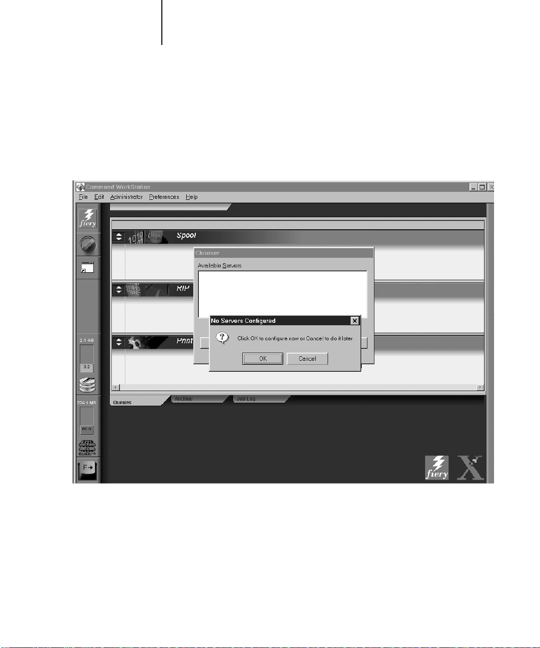
If the Command WorkStation has never been connected to a color server, a blank
Chooser list appears (see illustration below) and you are prompted to configure a
server. Configure a new connection by clicking OK. For information on configuring
the Chooser list, see Getting Started.
If you have previously configured the Chooser list and wish to select a different server,
select one of the server selection tabs just below the Menu bar (see page 1-8). If the
Command WorkStation was connected to a server previously, it automatically reconnects to that server, and the Log in/out slider appears. If you have any difficulties
connecting with the server, see Appendix C for error messages and troubleshooting
information.
Page 19

1-3 Starting up and logging in
1
Logging in
When the Command WorkStation has connected to a server, the Log in/out slider
appears, prompting you to enter a password. Before you log in, the Operator key is in
the vertical position, and the Administrator and Guest keys are in the flat (horizontal)
position. When you click your login level, the corresponding key turns to the vertical
position.
For Administrator or Operator access to the server, enter the password and click Log in
or press Enter . F or G uest access only, just click Log in. (If you change your mind about
logging in, or do not have the password you need, click Cancel.)
When you have entered the appropriate password and logged in, the Log in/out slider
retracts. The color of the key in the lock indicates your login level, and the full
Command WorkStation display appears. If your Fiery XJ is handling a large number of
print jobs, it may take a few moments to display the entire job list. When you reopen
the slider after you have logged in, the Log in button will have changed to the Log out
button.
og in/out slider
The three possible levels of access to Command WorkStation functions are
Administrator, Operator, and Guest. To enable maximum password protection, an
Administrator and Operator password must be specified in General/Passwords Setup
(see the Administrator Guide).
Page 20

1-4 Starting up and logging in
1
When both Administrator and Operator passwords have been specified, the access
levels are as follows:
Access level Privileges and password requirements
Administrator Has full access to all Command WorkStation functions,
including Setup options; Administrator password required
Operator Has access to all Command WorkStation functions except
Setup; Operator password required
Guest Can view job status, including archived jobs and the Job Log,
but cannot make changes to jobs or Setup; no password required
NOTE: Access privileges alone do not confer control of print jobs. If the operator is
going to manage all print jobs, the Administrator must also route all user jobs to the
Hold queue (that is, all jobs are spooled and held on the server). This is accomplished
by enabling neither the Direct connection nor the Print queue, in Printer Setup.
There is an additional password that can be specified: the Fiery WebSpooler User
password. This password is entered in a Java applet, the Fiery WebSpooler, running at
a remote user’s workstation. When this password has been specified in General/
Passwords Setup, most remote users become Guests; they can log in to the
Fiery WebSpooler but can only view print jobs. The person who enters the Web User
password has the same job management privileges as the Operator at the Command
WorkStation.
The Log in/out slider is also used to disconnect the Command WorkStation from the
server. To disconnect, open the slider and click the Log out button. See page 1-29.
Page 21
1-5 The Command WorkStation interface
1
The Command WorkStation interface
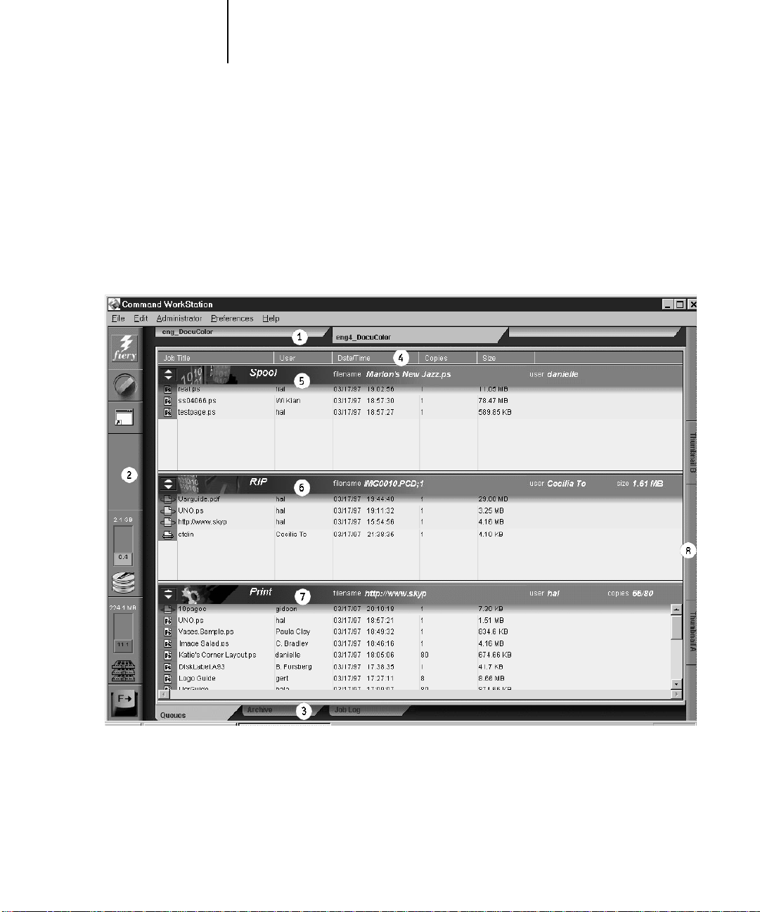
The display illustrated below is the default Command WorkStation display in the
middle of printing. It shows the elements common to all Command WorkStation
displays (1 through 4) and the Queues window elements (5 through 8). There are two
other windows, Archive and Job Log, which you access via tabs at the bottom of the
display (3). However, the Queues window is the one from which most Command
WorkStation operations are performed.
1. Server selection tabs
2. Sliders and system information
3. Window selection tabs
4. Job ticket information
5.–8. Queues window display
Page 22
1-6 The Command WorkStation interface
1
The Command WorkStation provides access to a great deal of information and many
features that are accessed in various ways—buttons, menus, double-clicking, and right
mouse commands. It is a powerful interface that allows for a great deal of interaction
and flexibility in the production process. This section describes each of the elements
that compose the Command WorkStation display.
Window area (Queues, Archive, Job Log)
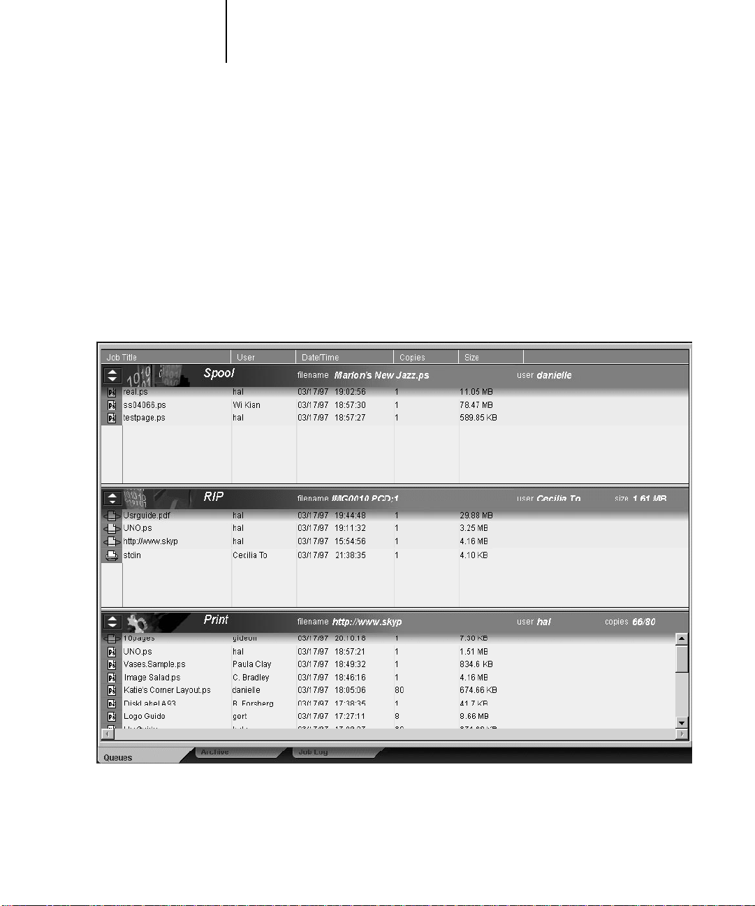
This area can display one of three windows: the Queues window (shown below), the
Archive window, or the Job Log window. The Queues window is the default window;
it shows spooled, processing, and printing jobs in a display that changes dynamically.
For details on the Queues window, see page 1-13; for details on the Archive window,
see page 1-23; for information on the Job Log window, see page 1-24.
Page 23

1-7 The Command WorkStation interface
1
Menu bar
The menu bar has five menus. When an action is not available in the current context,
the menu item is dimmed. When an item is marked with a check, selecting it again
reverses, or toggles, the command.
Menu Choose this To do this
File Exit Exit the Command WorkStation application and return to the
Windows 95 desktop.
Edit Delete Jobs From the Queues window, enable you to delete or one or more selected
jobs
Duplicate Jobs Enable you to duplicate one or more selected jobs in the Print area
Override Print Settings Let you override print settings for a selected job
Administrator Reboot Server If you logged in as an Administrator, perform a soft reboot
Clear Server Clear all jobs and queues from the server disk
Run Setup Start the setup program on the Command WorkStation
Preferences Enable Animation Animate the status bars
Expand/Collapse
Status Bars
Default Window Settings Restore default settings for the status areas, the column headings, and the
Help Enable Popup Help Enable you to view short captions by pausing the mouse over window
Widen the status bars to make them more visible from a distance
column widths
elements. The captions identify the main parts of the Command
WorkStation window.
Page 24

1-8 The Command WorkStation interface
1
Server selection tabs
The Server Selection tabs, just below the menu bar at the top of the display, are used to
switch between servers that are already connected to the Command WorkStation (if
your site has more than one server). If you click a blank tab, the Chooser list appears,
allowing you to connect to a server on the list or configure a new one. Configuring a
new server is described in Getting Started.
You can access the Server Selection tabs from all three windows (Queues, Archive, and
Job Log).
Page 25
1-9 The Command WorkStation interface
1
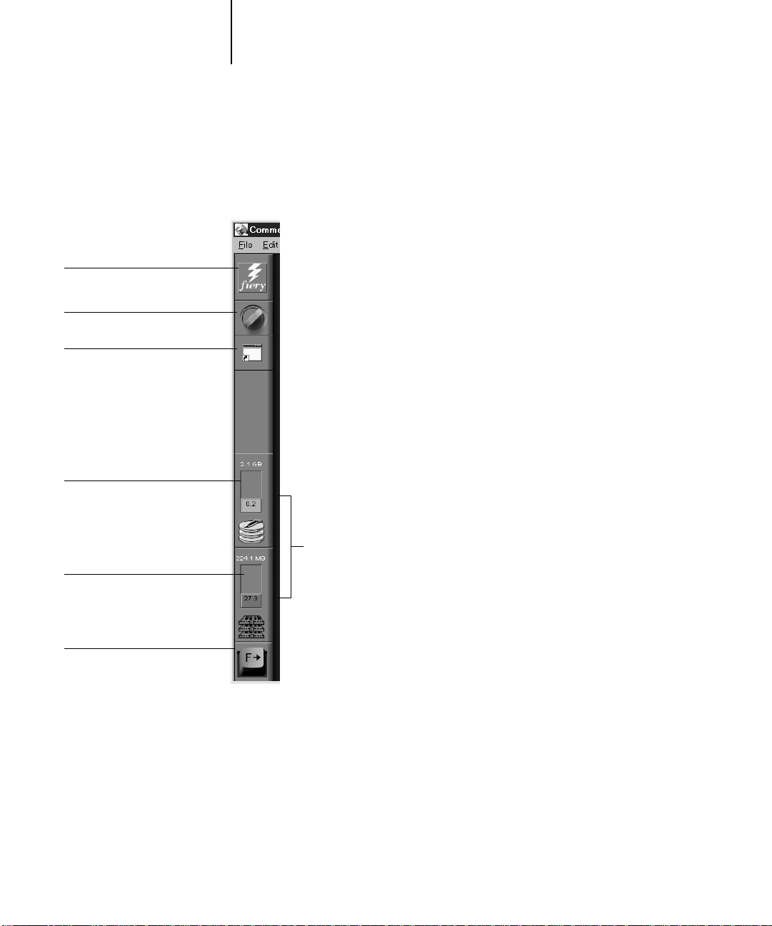
lick to view server information
lick to open the Log in/out slider
lick to start a Fiery XJ utility
Sliders and system information
Along the left side of the display are buttons you click to activate function sliders, and
icons that indicate system information.
Disk space availability
RAM availability
lick to open the Function
keys slider
Active server information
To retract any slider, click the icon at the far right of the slider.
Page 26

1-10 The Command WorkStation interface
1
Server information slider
The Server information slider displays name and version information about the
currently connected server and the Command WorkStation. To retract the slider, click
the server logo at the far right of the bar.
Log in/out slider
This slider is described in “Logging in” on page 1-3 and “Connecting and
disconnecting” on page 1-29. To retract the slider , click the lock icon at the far right of
the bar.
otal hard disk capacity
Disk space used
Utilities shortcut slider
The Fiery XJ Utilities shortcut slider provides quick access to the Fiery XJ Downloader
and Fiery XJ Print Calibrator. To retract the slider, click the screen icon at the far right
of the bar. To use the Fiery XJ Print Calibrator, see Chapter 3; to use the Fiery XJ
Downloader, see the User Guide.
Active system information indicators
Total RAM
RAM currently in use
The System information indicators show the current availability of hard disk space and
RAM on the currently selected Fiery XJ server.
NOTE: The Total hard disk capacity and Total RAM reflect the 128MB disk space and
32MB memory reserved for system use.
Page 27
1-11 The Command WorkStation interface
1
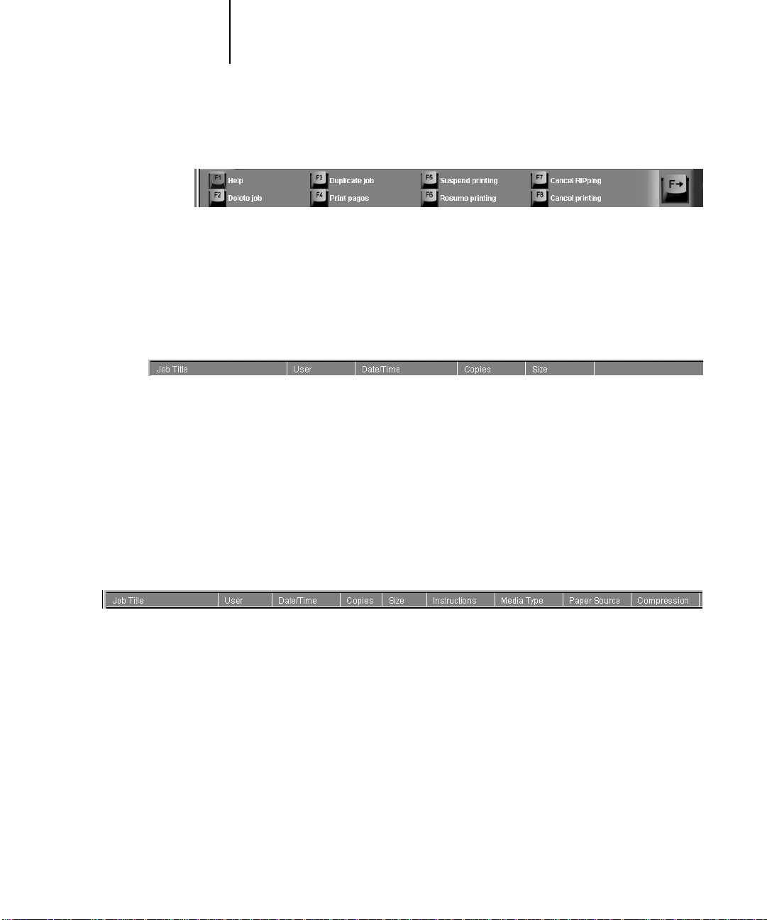
Function keys slider
The Function keys slider presents graphical keys for some of the most common
Command WorkStation functions. Click one of the function key icons to activate the
specified function. Using the corresponding function key from the Command
WorkStation keyboard has the same effect. To retract the slider, click the F- key icon at
the far right of the bar.
Job ticket information
All the jobs listed by name in the Queues and Archive windows can display the job
ticket information specified by the person who originated the print job. The
Command WorkStation can display this information because it parses the PostScript
file before it is RIPped.
You have considerable flexibility in arranging this information in the display. For
example, you can add Media Type to the display if you want to see which jobs call for
special paper or other media. You can choose not to display headers for options that are
not used at your site, or you can display all possible options and scroll to see the ones
that are less important to you. If you just want to experiment, when you are finished
you can choose Default Window Settings from the Preferences menu.
To customize the display in the Queues and Archive window, you can:
• Adjust the width of a column by clicking on the column border in the heading and
dragging left or right. Choose the options you want to display, and the sequence in
which you prefer to view them.
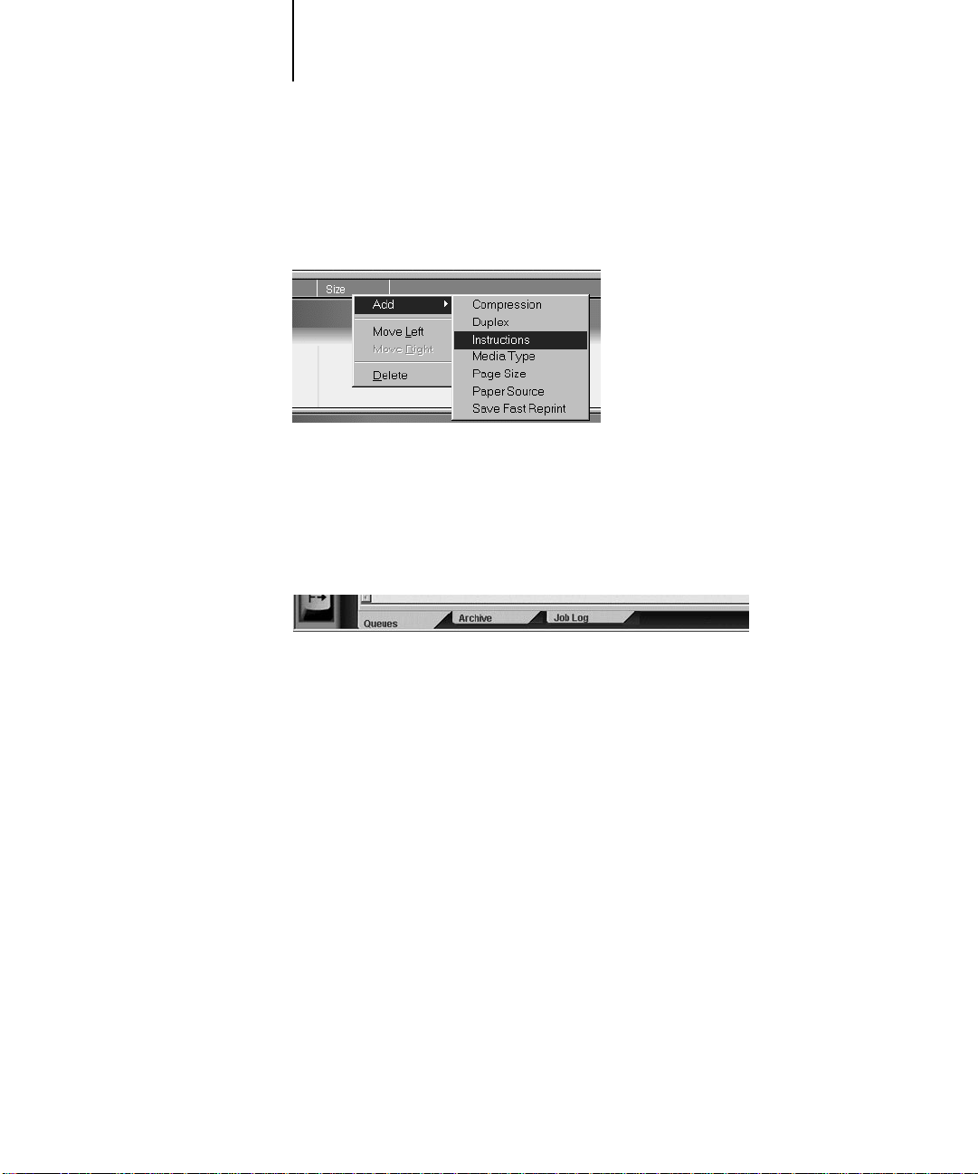
• Add, move, or delete a column by holding down the right mouse button on the
appropriate job ticket item; release the button after choosing a menu option:
Add one of the listed headings to the display at your mouse position
Move Left, Move Right—move the selected column heading left or right
Delete the selected column heading
Page 28
1-12 The Command WorkStation interface
1
The Job Title and User are required; but Date/Time, Copies, Pages, Size,
Compression, Duplex, Instructions, Media Type, Page Size, Paper Source, Save Fast
Reprint, Sorter, and Stapler headings are all optional.
For example, you can display the Instructions column, which shows information typed
into the Instructions field by the user, and you can reduce the width of the column so
you are just able to see whether or not there are instructions in it. To read the full
instructions, double-click the job and click Notes.
Window selection tabs
The Command WorkStation always starts out by displaying the Queues window, from
which you view current job processes and you control job flow and file storage. To go
to the Archive or Job Log window, click the corresponding tab at the bottom of the
Command WorkStation display.
Page 29

1-13 Queues window
1
Queues window
Spooling
RIPping
Printing
The Queues window is a dynamic display of the job staging area: jobs are lined up for
processing and printing, some of them are being held waiting for directions, some are
moving from one stage or queue to another and are finally dropped from the list, some
are held for processing by the operator, and some are held in a different queue in case
you need to reprint them.
One approach to understanding the dynamic display is to imagine the three parts of
the Queues window corresponding to the three stages of printing, illustrated as a
downhill flow.
Spooling—a PostScript file is saved on the server’s hard disk. The file can come in
packets from the network, or from another place on the server hard disk. Jobs are
added to a queue in the order in which they arrive, and they generally move to another
queue in the same order unless an operator has intervened to change the order.
Rasterizing (RIPping)—PostScript commands ar e interpr eted in the Fiery XJ to allow
the DocuColor 40 to print the file the way its originator intended. The result of this
interpretation is a raster file associated with the original PostScript file. I n this raster file
(raster image), color data is associated with each dot that can be rendered on the
printer. The color data tells the printer whether or not to apply cyan, magenta, yellow,
or black toner to each position on the page.
Printing—transferring the raster image from the server to the print engine at high
speed, freeing up RAM for the next job. While the PostScript file is usually saved to
disk, raster images are held in RAM during and after each print job. However, both
users and operators can request that the Fiery XJ save the raster image to disk along
with the PostScript file.
Saving the raster image to disk offers some advantages—raster files are already
processed so they print quickly, and each part of the raster file is still identified with a
page in the original document, which means that individual pages of a saved raster file
can be accessed.
Page 30
1-14 Queues window
1
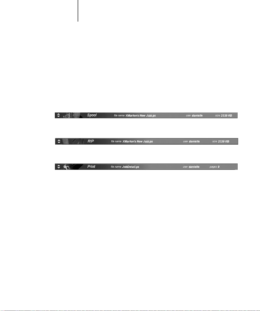
Status bars
Jobs actively involved in the three processes (spooling, rasterizing, and printing) are
listed in the status bars that span the Queues window.
Status bars show the filename, file size, and user name for the active process, and an
indication of its progress. Each status bar heads the list of jobs that have completed the
process. Thus, beneath the Spool status bar, you see a list of spooled files; beneath the
RIP status bar, you see a list of rasterized (RIPped) files. Beneath the Printing status
bar, you see a list of jobs that have already been printed.
Spooled jobs on Hold (yellow)
Active spooled jobs (white)
RIPped jobs on Hold (yellow)
Active RIPped jobs (white)
Printed jobs (white); some include raster files in RAM
When a job is being processed, provided animation is enabled (see page 1-7); the
corresponding status bar is animated, indicating that the process is active. Each status
bar lists the filename of the active job, the user name, and an indication of its size or
progress.
If an error occurs, the corresponding status bar alerts you by displaying a message on a
red background instead of the normal blue background. For example, the Print status
bar may display
Load A3 paper in upper tray on a red background.
Page 31

1-15 Queues window
1
Enlarging the status bars Click the small arrows at the left of the status bar to
enlarge the status bar display. Press Ctrl-E to enlarge all the status displays at the same
time, or choose Expand/Collapse Status Bars from the Preferences menu. Click the
arrows or press Ctrl-E again to reduce them to their smaller size, or choose Expand/
Collapse Status Bars again.
Changing proportions When the Queues window first appears, it is not the full
height of the frame. In this position you can view Thumbnail A without obscuring the
list of printed jobs. Double-click the bottom edge of the window to expand it to full
frame; double-click again to shorten the window.
By default, the status bars divide the window area into three equal parts. You can drag
the status bar or the bottom of each queue to change the proportion of the window
devoted to each job area. For example, drag the RIP status bar do wn if you have a long
list of spooled jobs that you want to see without scrolling.
Making space If your workflow includes holding many jobs, and you don’t want to
view the held jobs all the time, consider moving some of them to the Archive window.
You can move jobs back and forth between the Queues window and the Archive
window with a single right mouse command (see page 1-20).
Page 32

1-16 Queues window
1
Active jobs and Held jobs
In the description that follows, assume that the operator has full control of jobs; the
administrator has disabled the Direct connection and the Print queue, and all user jobs
come to the Hold queue. For more information about queues, see the Administrator
Guide.
The operator’s job management functions permit holding a job at any stage of the
process we have described, as illustrated below:
Spool
Spooled and held
Spooled for printing
RIP
RIPped and held
RIPped for printing
Print
Printed and held
Printed
Jobs that are held are shown with a y ellow icon in a yellow row, just beneath the Spool
or RIP status bar. Jobs that are held have to be activated with a right mouse command
in order to print.
Active jobs are shown in white with white icons; new jobs are added above older jobs.
PostScript and
raster data
Deleted
Page 33

1-17 Queues window
1
Job icons
There are three types of icons, for active jobs and jobs on hold.
Icon
PostScript icon
Printer icon
Raster icon
Active jobs
(white icons and rows)
PostScript data after
printing, raster deleted
PostScript or raster data
headed for printing
PostScript and raster
data after printing, ready
for fast reprint
Jobs on Hold
(yellow icons and rows)
Job from network or job on
Hold after printing (
)
Hold
PostScript data headed for
Print and Hold
PostScript data waiting for
RIP and Hold (white job line),
or already rasterized and held
Spool area
The job icons in the Spool area are described below:
Spool area icon What it indicates How long you see the job
1
Yellow PS icon
Job row is yellow
2
White printer icon
Job row is white
PostScript data from a user on
the network; no destination is
defined
PostScript data headed for
Print
Until a destination is chosen
Until the RIP is free
Print and
3
Yellow raster icon
Job row is white
4
Yellow printer icon
Job row is white
PostScript data headed for
RIP and Hold
PostScript data headed for
Print and Hold
Page 34

1-18 Queues window
1
The Spool area is both the receiving area for jobs from users on the network (Hold
queue) and the waiting area for jobs that will be RIPped (jobs in the Spool queue).
Hold queue jobs When printing requires an operator (because the Print queue and
Direct connection are disabled), the operator must assign a destination to all jobs
received from users on the network (icon 1 in the table above). Once assigned, jobs
(icons 2, 3, and 4) move down the Spool queue for processing. Jobs printed to the
Hold queue also require routing by an operator.
Print queue jobs When printing does not require an operator, network jobs sent to
the Print queue appear in the Spool area where they are shown with a white printer
icon (icon 2). Once the jobs ahead of them in the queue have been processed, they
proceed to be RIPped and printed without operator intervention.
Direct connection jobs Jobs printed to the D irect connection are not displayed in the
Command WorkS tation job lists. They are displayed briefly in the status bars (where
they cannot be selected) and in the Job Log.
RIP area
The job icons in the RIP area are described below:
RIP area icon What it indicates How long you see the job
1
Yellow raster icon
Job row is yellow
2
White printer icon
Job row is white
After a job is rasterized, it goes into the RIP area. The RIP area holds only raster data
(i.e., jobs that have been rasterized). Jobs in the RIP area are either waiting for the
copier to be free (Print queue jobs, icon 2 in the above table), or they are being held.
Held jobs in the RIP area have already been rasterized
been printed and their raster data has been routed back to the RIP area (Print and
Hold), where they are shown in yellow rows (icon 1).
Raster data, no destination
defined; may have been
printed before and held
Raster data headed for Print
in its turn; no hold defined
Until a destination is chosen
Until copier is free to print
the job
(RIP and Hold) or they have
Page 35

1-19 Queues window
1
Jobs held in the RIP area remain there until the operator assigns a new destination
(Print, Delete, Rename, Archive).
Print area
The job icons in the Print area are described below:
Print area icon What it indicates How long you see the job
1
White PS icon
Job row is white
2
White raster icon
Job row is white
The Print area contains jobs that have already been printed. These jobs were assigned
the Print destination (white printer icon in the Spool or RIP areas) without any Hold
instructions, therefore they all have white icons and rows.
NOTE: A job row that appears in light red indicates that a PostScript error occurred
while printing the job. To see the error, double-click anywhere in the row.
Newly printed jobs are added to the P rinted queue, and are shown at the top of the list.
Jobs are saved in the Printed queue until the job limit is reached. When the first job
over the limit is printed, the oldest job is deleted from the disk. The default job limit is
20 jobs. The value for Jobs Saved in Printed Queue can be changed by the
administrator in General/Server Setup on the Command WorkStation or Server Setup
on the Fiery XJ control panel.
PostScript data only—raster
data has been deleted
Raster and PostScript data
If RAM is needed to RIP an
active job, the raster data is
deleted and the job gets the
PS icon (icon 1, above)
Until the job limit is reached
Until the job is reprinted or
the job limit is reached
While it is printing, a job consists of PostScript and raster data. The raster data in
RAM is not cleared until the next print job needs to use the memory. As long as the
raster data is intact, the job can be reprinted quickly. Printed jobs that still have their
raster data are represented by a white raster icon in the Printed queue (icon 2 in the
previous table); jobs with only PostScript data r emaining are r epresented by a white PS
icon (icon 1).
Page 36

1-20 Queues window
1
Right mouse commands
Right mouse commands (commands activated by clicking the right mouse button) are
used to assign a selected job to a new destination or process. The right mouse
commands that are available at any time depend on the context; unavailable
commands are dimmed in the drop-down menu. Right mouse commands are available
in both the Queues and Archive windows.
TO ROUTE JOBS WITH RIGHT MOUSE COMMANDS:
1. To route a single job in the job list, move the mouse button to the job line and press
the right mouse button.
2. Select one of the commands or destinations and release the mouse button.
The command is carried out or the job is routed to the destination you chose.
Depending on your choice, the job line may reappear in a different part of the window
or a different window, or the job line may be deleted.
3. To route multiple jobs at the same time, select the jobs first.
Click in the job line to select the first job. Shift-click to select adjacent jobs;
Ctrl-click to select non-adjacent jobs.
N
OTE: Select jobs with the same job icon; otherwise, the destination options may not
be the same. For example, select multiple jobs in the Spool area, and choose Print.
4. With the cursor still in one of the selected job lines, press the right mouse button.
5. Select one of the commands or destinations and release the mouse button.
The command is carried out or the jobs are routed to the destination you chose.
The right mouse commands available for selected jobs in the Queues and Archive
windows are listed in the following table.
Page 37

1-21 Queues window
1
Choose this To do this Raster data is
Hold Hold the job in the current place
(except for a printed job, which
is moved to the Spool or RIP
area)
RIP and Hold RIP the job and hold it in the
RIP area
Remove Raster Remove the raster from a job
that has the raster (raster icon);
leave the PostScript job in place
Print Print the job in its turn. (RIP it
first if it does not have raster
data)
After printing, keep the printed
job in the Print area until the job
limit is reached
Print and Hold
(Like the user PPD
option Save Fast
Reprint)
Delete Delete the job from the list Deleted
Duplicate Create a duplicate job in the
Print the job in its turn (RIP it
first if it does not have raster
data)
After printing, hold the
PostScript data and the raster in
the RIP area
print area to use for different
print options or a different
destination (actually creates a
reference to the original job,
with the same name)
Held in RIP area, if included
with job
Held in RIP area indefinitely
Deleted
Temporarily held in RAM after
printing until memory is needed
for another job
Held in RIP area indefinitely
(saved to disk)
Duplicate is not available for
raster jobs
Rename Rename the job (PostScript file
with or without raster)
Unaffected, but associated with
the new name
Page 38

1-22 Queues window
1
Choose this To do this Raster data is
Process Next Give top priority to this job
Print the job (or RIP and then
print) as soon as processor and
copier are free, before other
waiting jobs
Option is dimmed if there are
no other waiting jobs
Archive Move the job to the Archive list Moved with the job
Thumbnail A Display a thumbnail view of the
job, in the Thumbnail A
window (raster jobs only)
This permits you to:
• Edit a job (raster jobs in RIP
area only)
• Open a full resolution view
Thumbnail B Display a thumbnail view of the
job, in the Thumbnail B
window (raster jobs in RIP or
Print areas only)
Handled the same way as for
other jobs with the same
destination
Saved, and may be changed if
job is edited
Unchanged
Page 39

1-23 Archive window
1
Archive window
The job icons in the Archive window are described below:
The Archive window displays jobs that have been moved from the Queues window; it
represents jobs saved to disk. The Archive window is a convenient place to store jobs
before or after printing them.
Archive icon What it indicates
PostScript data only—raster data not present or deleted
PostScript icon
Raster icon
Job was archived from the Spool area
Raster and PostScript data
Job was archived from the RIP area
As with the Queues window, you can select the headings for the display and use right
mouse commands; in the Archive window you can also sort jobs.
To Do this
Sort jobs in a
category, such as by
Date
Double-click the Date heading. A small arrow indicates
whether jobs are sorted in ascending or descending order.
Double-click again to sort in the reverse order.
Page 40

1-24 Job Log window
1
To Do this
Move a job out of
the Archive
window
Delete a job Right-click the job and select Delete.
Display or move
job ticket
information
headers in the
Archive window
Adjust the width of
a column
The icons that appear in the Archive window are always white, since they have no
destination (as long as they are in the Archive window).
Use right mouse commands. For example, to print a job,
right-click the job and select Print or Print and Hold. You
can also select and route multiple jobs. For details, see
page 1-20.
The other options, RIP and Hold, or Hold, move the job to
the Queues window (to the RIP and Spool areas,
respectively) without printing it; Remove Raster (which
applies only to jobs with the raster icon) leaves the job in the
Archive window.
Click the right mouse-button on the appropriate column
head; a drop-down menu lists the options that you can add
to the display. The categories are the same as in the Queues
window (see page 1-11) but you can arrange them
differently. When you re-open the Queues window, the
headings are the way you set them earlier in the Queues
window.
Click the column border in the heading and drag left or
right.
Job Log window
The Job Log is a list of all printed jobs, the date and time they were printed, and all the
characteristics of the job. The Job Log is stored on the server disk; you can access it
from the Command WorkStation or the Fiery WebSpooler.
When you open the Job Log, you can choose to display the entire log or just the jobs in
a specified date range.
Page 41

Print job log
Save job log
1-25 Job properties
1
Printing and clearing the Job Log automatically You can decide how you want to
handle the Job Log. If you have Administrator privileges, you can choose Run Setup
from the Administrator menu and enter your preferences in the Job Log Setup. You
can choose to print the Job Log automatically every 55 jobs, or print and clear the Job
Log automatically every 55 jobs. You can choose the Job Log page size.
Exporting, printing, and clearing the Job Log From the Job Log window, you can
print the entire Job Log or export it to a tab-delimited file at any time. Operators and
administrators can clear the Job Log by clicking the trash icon.
When an Administrator clears the server or installs new software, the Job Log is also
cleared.
You can adjust the column widths in the Job Log display by clicking on the column
border in the heading and dragging left or right. For more information, see Chapter 2.
Enter date range
Job properties
To see a job’s properties, or change them, double-click the job line in the Queues
window or Archive window, or choose Override Print Settings from the Edit menu.
NOTE: The Job Properties dialog box displays all the job settings encoded by the
PostScript printer driver that can be decoded by the Fiery XJ. If you as operator have
not changed anything, these are the settings a user entered before sending the job. Job
properties that cannot be decoded at the present time include number of copies, and
collation (collated copies option).
Page 42

1-26 Job properties
1
In addition, when the Job Properties dialog box opens, the number of copies is always
shown as 1, even if the user requested multiple copies, and the page range is All pages.
All pages denotes all the pages specified by the user in printing the job; it may not
include all the pages in the original document on the user’s disk. Similarly, 100% scale
indicates 100% of the magnification specified by the user.
The Job Properties dialog box does display all the remaining user settings, including
user Instructions and Notes fields.
• Instructions fields are intended to be viewed and annotated by the operator, but
their contents are associated with the job and are deleted when the job is deleted
after printing.
• Notes fields can be viewed but cannot be changed by the operator; their contents are
transcribed to the Job Log just as the user sent them.
NOTE: Even if you cannot view all the user’s settings before the job prints, the job still
prints with correct settings.
Page 43

1-27 Editing and merging documents
1
You can use job properties in several ways:
• To check a user’s print settings, especially notes and instructions
• To override a setting based on copier output or other copier conditions
• To change settings for a duplicate of the original job
• To print a single copy of a job, or a selected page range, before printing the number
required by the user
For more information on job overrides, see Appendix A.
Editing and merging documents
The Command WorkStation’s Thumbnail and DocBuilder tools allow you to preview
and edit raster data. DocBuilder enables you to merge raster data from more than one
file, not necessarily from the same application or even the same computer platform.
An outline of its powerful features follows; for specific information and applications,
see Chapter 2.
Thumbnails
You can see a thumbnail view and full-screen previews of any file that is currently
RIPping, or any file that has been RIPped and held to disk. You can also edit the raster
file—you can change the sequence of pages, delete pages, and duplicate pages, all from
the Thumbnail A view. You can save the changed file as a new printable document.
When you right-click a raster file and choose Thumbnail A, the Thumbnail A slider
opens automatically, displaying thumbnails of the editable file. Clicking on the
Thumbnail tab retracts the preview.
Page 44

Thumbnail B (source)
Thumbnail A (target)
1-28 Editing and merging documents
1
DocBuilder for merging raster files
Thumbnail B is another preview window. You can use the document displayed in
Thumbnail B as a source for editing the document shown in Thumbnail A.
You can merge documents by dragging (copying) one or more entire pages from
Thumbnail B to Thumbnail A. Right mouse commands when you click a page in the
Thumbnail A window, and Ctrl-Z (Undo) give you additional editing possibilities.
This creates a new document in the Thumbnail A window.
You can merge pages from multiple documents into the Thumbnail A document by
opening documents one after another in the Thumbnail B window. Documents in the
Thumbnail B window are view-only, and while you can copy pages from Thumbnail B
to Thumbnail A, you cannot edit the Thumbnail B document. A merged document
that you create in Thumbnail A can be saved (with a different name) as a new raster
data file.
Page 45

1-29 Connecting and disconnecting
1
Merging documents from the raster files eliminates the limitations of particular
software applications. You can merge PostScript raster pages of documents of different
types, even different computer operating systems. You can merge color pages from
graphics programs with text pages from a word processor.
Full-screen preview
Double-clicking on any page in either Thumbnail windo w opens a full-scr een pr eview
of the page. However, this is a view-only display, and it takes time to retrieve the data.
Once begun, the process cannot be canceled. Click on the left or right arrows at the
top left of the full-screen preview to display adjacent pages. Click on the close button
at the far right to close the full-screen preview.
Connecting and disconnecting
To disconnect from the current server, open the Log in/out slider and click Log out in
the Password section.
To connect to an additional server, click one of the blank Server Name tabs at the top
of any window . F rom the Chooser list, select the appropriate server, or configure a new
one. See “Connecting to a server” on page 1-2. A limit of three Fiery XJ servers can be
connected to a single Command WorkStation.
Page 46

2-1 Communicating with users
2
Chapter 2: Managing Print Jobs
This chapter provides some general information about managing printing with the
Fiery XJ Color Server and the DocuColor 40, and gives you some hints on using the
Command WorkStation windows to monitor and manage print jobs. It suggests ways
of educating the people who originate print jobs so that their jobs are more likely to
print correctly the first time. The chapter also follows the course of a print job and
shows possible ways to expedite jobs and take advantage of the special capabilities
provided by the Command WorkStation.
Communicating with users
The Command WorkStation interface facilitates communication between users and
operators. All the same, users who originate print jobs may need to become better
informed about the Fiery XJ and the DocuColor 40 so they can choose the appropriate
options for their jobs.
What the user needs to know
You or the network administrator should consider supplying some of the following
information to your users:
• Printer name on the network, and server(s) sharing the printer
• User’s access status
Do all jobs require operator intervention because they go to the Hold queue? If not,
which connections are published—Direct and/or Print Queue?
• How long you will hold jobs on the server before you delete them
• List of default printer settings and other settings from the Configuration page
• List of installed fonts
Do the users’ applications download fonts automatically? I f not, can users download
fonts, should they embed them in documents, or should they supply them to you in
some other way so you can download them? (For information on using the Fiery XJ
Downloader, see the User Guide.)
• Company requirements for Notes fields (information which appears on the J ob Log)
For example, department name, account code, phone number or extension. Is some
information mandatory at your site?
Page 47

2-2 Managing Print Jobs
2
• Resident calibration target and type, and date of current measurements
• Custom-1 and Custom-2 calibrations
Are they available? What type of target do they represent? Users see these print
options (in Calibration/Simulation) and should not select them if there is no
Custom-1 or Custom-2 target on the server.
• IP address or DNS name of printer so users can access Fiery W ebTools, at least to see
if their jobs have printed
• Installed options: sorting, stapling
• Available media, alternative choices, standard tray/media configurations
• Suggestions for the Instructions field
• Information users might find in the WebLink web site
• Instructions for setting up the printer on client computers
• Sources of PostScript printer drivers, PPDs, color reference files, and additional
information
• Recommended PPD settings
• Conflicting settings and common PostScript errors
How users communicate print requirements
Explain to remote users the information you check and what you need to know in
order to print the jobs they send. The Instructions field is suited for communication
about the job requirements. Notes fields appear in the J ob Log so they are more suited
for accounting, billing, and job cost information.
Users can provide you information with the print job, for example:
• Information can be entered in the Instructions field or the Notes fields—special
requirements at your site, such as:
User name, phone, or extension
Priority, due date, request for notification
Number of copies needed
Collation
Special paper stock or transparency media
Purpose of job (proof, final output, simulation)
Request for approval after printing one copy
Request that operator do color check
Page 48

2-3 Communicating with users
2
Hold job for future printing or future reprinting
Merge with another job, and merging instructions
Type of slip sheet
Quantity of paper required
Future requirements for the job
• Job ticket information provided by PPD option settings, such as:
Save Fast Reprint
Collate
Duplex
Page turn
Paper source
Media type
Slip sheet
Preparing the Command WorkStation window
When you control printing, you want the important information to be accessible at a
glance. The easiest way to view job ticket information is to rearrange the headings in
the Queues window. The Job Title and User name are always at the left, but you can
tighten the columns so you see what you need, and move and add other column
headings so the most important information is visible without scrolling.
TO CUSTOMIZE THE QUEUES WINDOW DISPLAY:
1. Right-click in the column heading.
A menu appears. The Add submenu lists the headings that are not already displayed.
2. Choose the options you want to display, and the sequence in which you prefer to view
them.
Add, delete, or move a column by holding down the right mouse button on the name
of the appropriate column head; release the button after choosing one of the menu
options:
Add one of the listed headings to the display at your mouse position
Move Left, Move Right—move the selected column heading left or right
Delete the selected column heading
Page 49

2-4 Managing Print Jobs
2
3. Adjust the column widths.
The Job Title and User are required; but Date/Time, Copies, Size, Compression,
Duplex, Instructions, Media Type, Page Size, Paper Source, Save Fast Reprint, Sorter,
and Stapler headings are optional.
Adjust the width of a column by clicking the column border in the heading and
dragging to the left or right. You can change the column widths at any time.
If you display the Instructions column, which shows information typed into the
Instructions field by the user, you can reduce the width of the column so you can just
see whether or not there are instructions in it.
4. With a narrow Instructions column, if you want to read detailed instructions, doubleclick the job and choose Notes from the Job Properties window.
This also allows you to read the notes.
You can edit or annotate the information in the Instructions field if you wish. It
remains with the job as long as the job is on the server. The operator cannot edit the
Notes fields.
Workflow scenarios
The workflow at your site will depend on the number and complexity of jobs and the
amount of responsibility given to the operator. This section suggests some ways you
might interact with a job.
Scenario 1 At this site, the Print queue is enabled, and anyone at the Command
W orkS tation can view the progress of jobs. A small job is sent to a server and copier that are
not busy . You watch the job progress from the top to the bottom of the Queues window.
The green light on the Fiery XJ flashes, the network icon blinks; on the Command
WorkStation the Spool status bar is animated and the job title appears. As soon as
spooling has finished, the Spool status bar is cleared and the RIP status bar animates.
Page 50

2-5 Workflow scenarios
2
Almost immediately thereafter, the RIP status bar is cleared and the Print status bar
animates. The printed job is listed belo w the Print status bar and the job pages emerge
from the DocuColor 40. You move it to the mailbox of the person who sent the job.
Scenario 2 At this site, all jobs come to the Hold queue, therefore they require
operator intervention to proceed.
Again, the green light on the Fiery XJ flashes, the network icon blinks, the Spool status
bar is animated, and now in the Spool area (below the status bar) the job title comes
into view. In a few moments the job is on the list, and you have time to scan the
headings for the job ticket information—media type, special instructions, copies, and
pages.
Are you ready for this job to print? Do other jobs have priority? What is the job for—
is it final output or a test print? The first choice is whether to put the job in the print
queue or hold it before processing it further . If you do nothing, the job remains in the
Spool area, and the file remains on the server disk.
Perhaps this is a routine job and does not call for special handling. You right-click the
job and choose Print. You notice the RIP status bar animate, and almost immediately,
the Print status bar animates. The printed job is listed below the Print status bar and
the job pages emerge from the DocuColor 40.
The next job is a large job that you have not seen before. The Instructions field
indicates that the originator of the job wants to check one printout of the job before
you print another 50 copies. You make sure the copies field is set to 1, right-click the
job, and choose Print and Hold.
The RIP status bar animates and displays the job title, and then the Print status bar
and copy 1 of the job emerges from the DocuColor 40. You call the person who sent
the job for approval. When the job is approv ed, you right-click the job now being held
in the RIP area and choose Print.
Scenario 3 Everyone has discovered the DocuColor 40 on the network and jobs are
coming in rapidly. You right-click several routine jobs in the Spool area and choose
Print to let the server print them one after the other . You choose Print and Hold if you
know you will be reprinting the job soon. You move jobs that have more detailed
instructions (or need to be printed with similar jobs) to the Archive window (rightclick Archive. You remove printed jobs from the output trays and replenish media.
Page 51

2-6 Managing Print Jobs
2
While some jobs are flowing through the queues and printing, you are preparing for
jobs that require more attention, such as obtaining special paper, using DocBuilder to
merge two documents, or notifying the originator of a job that a PostScript error
occurred.
Before you load special paper, you make sure all pending jobs are in holding areas.
When an especially important job is spooled for RIPping, you right-click Process Next.
Y ou flip back and forth between the Archiv e and Queues windo w. You use the Archive
window to sort jobs into groups with similar requirements, such as media type, user
name, or another setting, and print all the jobs of the same type in sequence.
Using the copier
If you have a copier job that has priority over the spooled incoming print jobs you can
temporarily close the Fiery XJ connection to the DocuColor 40 and then re-open it
when you have finished copying.
When there are no active printing jobs competing for the copier engine (no white job
lines in the Spooler or RIP area) you do not need to suspend printing in order to make
copies.
TO GIVE THE COPIER TOP PRIORITY AND LATER RESTORE PRINTER PRIORITY:
1. Press F5 on the Command WorkStation keyboard to suspend printing, or click the F5
button (Suspend Printing) in the Function keys slider.
This suspends printing temporarily . J obs continue to spool and process on the server as
long as disk space and RAM are available.
2. When you have finished with the copier job, press F6 or click the F6 button to resume
printing.
Page 52

2-7 Canceling jobs
2
Canceling jobs
You may need to cancel a job after it has been routed for processing or printing.
Canceling at the Control Panel If you are at the Fiery XJ, the most direct way to
cancel a job is to press the top button on the server Control Panel while you can read
the name of the job that is processing or printing. For more information on the
Control Panel, see the next section.
Cancel Job
User Name
Copies
1/100
Print
The Cancel command can also be entered at the Command WorkStation, as follows:
Canceling jobs queued for printing Click the job line and with a right mouse
command choose Hold if you plan to print the same job later, or Delete if you don’t.
Canceling jobs during processing While a job is being RIPped, and its name
appears in the RIP status bar, press
processing. Or, if the Function keys slider is open, click the F7 button.
When the RIP job is canceled, the Canceling message appears in the RIP status bar
and on the Fiery XJ Control Panel. The name of the canceled job appears in the Job
Log.
Canceling jobs during printing While a job is printing, and its name appears in the
Print status bar, press F8 at the Command WorkS tation. Or, if the Function keys slider
is open, click the F8 button.
When the print job is canceled, Canceling appears in the Print status bar and on the
Fiery XJ Control Panel.The name of the canceled job appears in the Job Log.
Cancel Job
Job Name
User Name
###### KB
RIP
F7 at the Command WorkStation to cancel
NOTE: When a job is canceled, all the paper in the process of printing is ejected from
the copier. Therefore, canceled jobs may be partially printed, and may include pages
with one or more missing color planes, or pages that are completely blank.
Page 53

2-8 Managing Print Jobs
2
Using the Fiery XJ Control Panel
You can use the Fiery XJ Control Panel to view status information, print special pages,
and set up printing. While most of the Control Panel display has a counterpart in the
Command WorkStation, you can view current functions on the Control Panel even
when the Command WorkStation is not connected to it or is not running.
The Control Panel comprises the following parts:
• Activity light that indicates current Fiery XJ activity
• Line selection buttons
• Up and down arrow buttons
• Menu button
• Display window showing status information and options for setting up the Fiery XJ
Activity light
Display window
Up and down arrow buttons
Menu button
Line selection buttons
Activity light
The activity light indicates the current Fiery XJ activity. If the light is:
Solid red There is an error causing printing to be disabled, and the
Fiery XJ is idle.
Flashing red There is an error causing printing to be disabled, but the
Fiery XJ is still processing. The light changes to solid red
when it has finished processing.
Page 54

2-9 Using the Fiery XJ Control Panel
2
Solid green The Fiery XJ is idle.
Flashing green The Fiery XJ is processing or printing a job, or
communicating with a remote computer.
No light The Fiery XJ is off or starting up.
Buttons
Line selection
buttons
Up/down
arrow buttons
Menu button Press this button to view other screens. Under normal
There are four line selection buttons on the right side of the
Control Panel. Use these buttons to select the command
displayed on the corresponding line of the display window.
When a button is active, a special character (>) appears in the
display window next to the button.
Use these buttons to scroll to different screens in multiscreen lists, to select Setup options from a list of available
options, and to scroll alphanumeric characters.
operation, the Control Panel displays the Info, RIP, or Print
Status screen with information about the status of the
Fiery XJ. If you press the Menu button, the Functions menu
is displayed and you can perform additional operations. If a
job is processing or printing, press the Menu button to cycle
among the active screens.
Page 55

2-10 Managing Print Jobs
2
Display window
The display window provides information about the status of the Fiery XJ, displays
menu information, and enables you to view and edit information in the Setup menus.
The last line of the display window displays text that tells you what screen you are
looking at and highlights one of the icons to indicate what the Fiery XJ is doing. Only
the icons for the screens that are currently available appear. The menu button cycles
among the active screens.
The screens are:
Alert Status If there is a problem with processing a job or printing functions,
Print Status When the Fiery XJ is printing or scanning a job, the Print S tatus
an error message appears on the Control Panel. For information
on error messages, see Appendix A, “Error Messages.”
screen appears. This screen displays the following:
Cancel Job—Press the top line selection button to cancel the job
currently printing.
User name—The name of the user who sent the job currently
processing.
Pages/Total—The number of copies of the current page printed
and the total number of copies of the page requested.
RIP Status When the Fiery XJ is processing a job, the RIP Status screen
appears. This screen displays the following:
Cancel Job—Press the top line selection button to cancel the job
currently processing. The Fiery XJ cancels the job before
printing begins.
Document name—The name of the document currently
processing.
User name—The name of the user who sent the job currently
processing.
Kilobytes—The amount (in kilobytes) of the job processed so
far.
Page 56

2-11 Using the Fiery XJ Control Panel
2
Info Status When the Fiery XJ is not processing or printing a job, it displays
Functions You can press the Menu button to display the Functions menu.
Network The network icon appears at the bottom left of any of the other
information about the current server and software. It displays the
following information:
Server Name—The Fiery XJ name.
Status—The current status of the Fiery XJ. The Fiery XJ status
can be: Idle, Initializing, Busy, Processing, or Printing.
Number of MB—The space (in megabytes) available on the
Fiery XJ hard disk.
Version—The system software version running on the Fiery XJ.
Use the up and down arrow buttons to scroll through the list.
Press the line selection button to the right of a command to
select that command.
screens when a job is being sent to the Fiery XJ, either over the
network or through the parallel port. The network icon also
appears, together with a flashing green activity light, when a
remote utility is running.
Page 57

2-12 Managing Print Jobs
2
Functions menu
The Functions menu gives you the same options as the Function keys slider on the
Command WorkStation, and the F-keys on the keyboard. You can choose the
following commands from this menu:
Choose: To do this:
Print Pages
Print special pages from the Fiery XJ. You can print the
following pages from the submenu that appears:
Test Page—A Test Page enables you to confirm that the
Fiery XJ is properly connected to the copier, and provides
color and grayscale samples to troubleshoot problems with
the copier or the Fiery XJ. The following information is
listed: Server Name, Printer Model, Color Mode,
Calibration time and Target, Color Rendering Dictionary,
and Date and Time printed.
Configuration—Prints the Configuration page, which
gives the current server and device configuration. This
page lists general information about the hardware and
software configuration of the Fiery XJ, the current options
for all Setup settings, information about the current
calibration, and the Ethernet and token ring addresses of
the Fiery XJ.
Job Log—Prints a log of the last 55 jobs. For information
on the fields in the Job Log and on printing it in other
forms, see “Using the Job Log” on page 2-18.
Control Panel Map—Prints the Control Panel Map, which
is an overview of the screens you can access from the
Control Panel. For information about using these screens
to set up the Fiery XJ, see the Administrator Guide.
Color Charts—Prints samples of the RGB, CMY, and
PANTONE colors available from the Fiery XJ.
Font List—Prints a list of all fonts currently on the
Fiery XJ hard disk.
Page 58

2-13 Previewing a print job
2
Choose: To do this:
Suspend Printing
Resume Printing
Reboot Server
Previewing a print job
You can preview the pages of a job while it is printing.
Suspend communication between the Fiery XJ and the
copier. You must suspend printing if you want to interrupt
the current Fiery XJ job so that you can use the copier to
make copies. Jobs continue to process on the Fiery XJ.
After you make the copies, select Resume Printing to
continue printing jobs from the Fiery XJ and networked
users.
Resume communication between the copier and the
Fiery XJ after you have finished making copies.
Shut down all Fiery XJ activity in the correct manner and
then restart. You should use this option instead of the
switch on the rear of the Fiery XJ.
TO VIEW THUMBNAILS OF A PRINTING FILE:
Displaying a preview of the
currently printing job
When the button is down,
thumbnail is a preview of
an editable raster file
1. Click the Thumbnail A tab at the right of the Queues window to open the slider.
2. Choose a file in the Spool area and select Print.
As soon as each page is processed, it is displayed in the thumbnail window.
Page 59

2-14 Managing Print Jobs
2
You can also open an editable thumbnail view of a file that has already been rasterized,
and use thumbnails to do electronic collation or document merging.
3. When you have finished viewing, click the Thumbnail A tab again.
DocBuilder
The ability to work with raster files gives you new opportunities to combine
documents from different sources into a single printer file. For example, you can
combine full color covers and chapter head pages created in a page layout application
with two-color text pages created in a document processing application. Or, you can
customize a slide presentation by inserting slides from a different presentation.
You can display two raster files at once: a source file and a target file. The target file is
displayed in the Thumbnail A window, the source in Thumbnail B.
You cannot create a new PostScript file in this process; you must continue to print the
rasterized merged file, which has references to the original PostScript files.
TO VIEW AND EDIT THUMBNAILS:
1. Right-click the job line and select Thumbnail A.
The file must be a held job with a raster icon.
2. In the Thumbnail window, right-click a thumbnail image to see the menu options for
Thumbnail A. If you wish, choose one of the following options:
Delete deletes the currently selected page
Duplicate duplicates the page
Open Preview opens a full-screen preview of the currently selected page
Page 60

2-15 DocBuilder
2
3. When you are finished editing, click the Thumbnail A tab. If you have edited
From the open preview, click the left or right arrow at the top left to view a full-screen
preview of other pages in the document (if there are any). Click the close box at the top
right to return to the thumbnail view.
Thumbnail A, you are prompted to save the job (click Yes) and enter a new name. Enter
a new name and click OK.
The new raster file is now in the RIP area, ready to print. If you renamed the new
raster file, the original source file remains held in the RIP area.
TO MERGE TWO DOCUMENTS:
1. In the Thumbnail A window, display the document you wish to edit.
The document must be a raster file held in the RIP area.
2. Right-click another source document file (a held job with a raster icon) and select
Thumbnail B.
The Thumbnail B tab opens a second thumbnail view which cannot be edited but can
be a source for pages added to the document in Thumbnail A.
NOTE: To merge documents, the page size in the source document must be the same as
the page size in the target document.
Page 61

Thumbnail B
2-16 Managing Print Jobs
2
3. In the Thumbnail B window, click once on a page or a range of pages to select it; and
then release the mouse button and click and drag to paste it in a different location.
Drag the single-page or multi-page icon to the new location in the Thumbnail A pages.
Drag a Thumbnail B page o ver a page in Thumbnail A to replace the page, or drag the
icon to a new position between pages or before or after a page in Thumbnail A.
Page insertion icons:
…
Single-page icon Multi-page icon
Page 2 came from the
document in Thumbnail B
You can use Ctrl-Click to select multiple, non-sequential pages in Thumbnail B.
Multiple undos are available; use Ctrl-Z to undo all the way back to your first edit.
There is no Redo function.
Page 62

2-17 Overriding print settings
2
4. To close the Thumbnail view, click once on the same tab you used to open it
(Thumbnail A or Thumbnail B tab).
5. If you have edited Thumbnail A, you are pr ompted to save the job (click Yes) and enter
a new name. Enter a new name and click OK.
The new raster file is now in the RIP queue, ready to print, together with the original
source and target files.
Overriding print settings
You can view user job settings and override them. Double-clicking a job in the Queues
window or the Archive window, or choosing Override Print Settings from the Edit
menu displays the Job Properties dialog box. If you want to retain the job with its
original settings, Duplicate the job and Rename the duplicate (with right mouse
commands) before you change settings. The settings you can access are described in
detail in Appendix A.
Managing jobs with multiple color servers
At the Command W or kStation you can view and manage jobs processed by up to three
Fiery XJ Color Servers.
TO MANAGE JOBS ON MORE THAN ONE SERVER:
1. Configure the Chooser for the first server and log in.
See Getting Started for information on configuring the Chooser list.
2. Route and manage jobs as usual.
3. Click a blank server selection tab and configure the second server.
4. Log in to the second server.
The Command WorkStation windows show the job lists for the second server. You can
route and manage the jobs processed by this server as long as you are logged in.
5. To switch servers, simply click the other server selection tab.
Once you have logged in, you do not need to log in again unless you have logged out.
Page 63

2-18 Managing Print Jobs
2
If both servers are extremely busy with continuous jobs, you may see some delay in
updating the Command WorkStation window when you switch between servers. Job
lists may be blank for some seconds until updating is complete.
Using the Job Log
Chapter 1 introduced the Job Log, which is the list of all printed jobs, including the
date and time they were printed, and all the characteristics of the job. It explained that
the Administrator can set Job Log preferences for clearing and printing the Job Log
automatically, and for Job Log page size (page 1-24).
After displaying the Job Log you can print it or export it to a tab-delimited file. The file
can be imported into a spreadsheet or word processing application for job accounting
purposes.
Even if only a portion of the Job Log is display ed (such as jobs for the current day), the
entire Job Log is exported or printed. Therefore, after saving or printing it, you may
prefer to clear the Job Log; you clear the Job Log by clicking the trash icon.
Page 64

2-19 Using the Job Log
2
TO DISPLAY, PRINT, AND SAVE THE JOB LOG:
1. Click the Job Log window selection tab to display the Job Log.
By default, the Job Log displays all the jobs since the Job Log was cleared.
2. Specify the date range at the top of the Job Log window. Click From if you want to
specify a period of time for the Job Log, and enter the starting and ending dates.
The Job Log window displays a list of all the jobs and the following information about
them: status, document name, user, date, start time, end time, process time, size,
device, page size, media, number of originals, number of color pages, number of black
and white pages, and total number of pages.
The information in the Note 1 and Note 2 fields is displayed if users entered this
information when they printed.
NOTE: The Notes field is supported only by the Adobe PostScript printer driver.
Use the scrollbar at the bottom of the window to view all the fields in the Job Log
window.
Page 65

2-20 Managing Print Jobs
2
The text in the Status column provides information about the job:
OK The job was printed normally
Cancel The job was canceled before printing was completed
Error An error occurred during processing or printing
Icons appear above the Job Log. The icons are:
Update Click to update the information in the Job Log window
Prints Click to print the entire Job Log to the DocuColor 40
Export Click to export the entire Job Log to a tab-delimited file
Delete Click to delete the Job Log (you will be asked for
confirmation)
3. To print the entire Job Log, click the Print icon.
The Job Log prints to the current Fiery XJ. When you print the Job Log, totals are
printed for all appropriate columns.
4. To export the entire Job Log, click the Export icon.
An export dialog box enables you to name the tab-delimited file and save it anywhere
on your disk.
Page 66

3-1 Introduction
3
Chapter 3: Color Calibration
Calibrating the Fiery XJ ensures consistent, reliable color output. You can calibrate the
Fiery XJ with the Fiery XJ Print Calibrator, a utility that is available to the Command
WorkStation operator, and a densitometer. By connecting an X-Rite DTP32
automatic scanning densitometer to the Command WorkStation serial port, you can
quickly measure color patches and download measurements to the Fiery XJ.
This chapter describes the purpose of calibration and explains how to calibrate the
Fiery XJ. It also describes advanced calibration features.
Introduction
A calibration is generated from two components that originate separately:
measurements and a target. Measurements represent the actual color behavior of the
copier; they are computed from densitometer readings. Targets represent the goal of
printing, such as obtaining pleasing color from the copier, or simulating the inks used
on an offset press. A set of copier and press targets is provided with the Fiery XJ.
Calibration pairs a particular set of measurements with a particular target that you
selected.
Once you have calibrated the Fiery XJ with the Fiery XJ Print Calibrator, a calibration
is stored on the Fiery XJ; this calibration will be referred to as the resident calibration.
The resident calibration is applied to all print jobs unless the user specifies otherwise.
Users can also select a different target from their Print dialog box, or they can select
None (no calibration).
NOTE: Changing the resident calibration has the potential to affect all jobs for all users,
so you may want to limit the number of people authorized to use Fiery XJ Print
Calibrator. If the administrator has specified an administrator or an operator password
for the Fiery XJ, you will be required to enter one of these passwords before you can
use Fiery XJ Print Calibrator with that Fiery XJ.
Page 67

3
Resident calibration is
Printer’s default
Copier target calibration
3-2 Color Calibration
Calibration on the fly
Users who send print jobs to the Fiery XJ and use the Adobe PostScript printer drivers
provided (version 8.3.1 on the Macintosh, version 3.0.1 on Windows 3.1x, or version
4.1.1 on Windows 95) can select a target on a job-by-job basis, using the
Calibration/Simulation option.
The Fiery XJ stores several targets, and a separate calibration is created for each of the
stored targets. When a user selects a different target for a job, the calibration generated
for the selected target is applied to that job only. The server’s resident calibration
remains unchanged. As a consequence, users do not have to agree or compromise on
the goals of their print jobs.
The options in the Macintosh interface are shown below.
Press target calibration
Custom calibrations, if operator
has defined them
Understanding calibration
The Fiery XJ allows you the flexibility to choose a standard calibration or a custom
calibration. A standard calibration uses one of the standard targets with a new set of
measurements. You can also customize one of the provided targets for your own
purposes, for example, to achieve particular color results or emulate another printing
device. A custom calibration uses a customized target with a new set of measurements.
You can make a customized target the default target, or you can make it available to
users on a job-by-job basis.
Calibration allows you to:
• Maximize the color reproduction capabilities of the Fiery XJ
• Ensure consistent color quality across time
• Produce consistent output across Fiery XJ servers of the same kind
Page 68

3-3 Understanding calibration
3
• Use the Fiery XJ as a proofing system
• Achieve better color matches when reproducing spot colors, such as PANTONE
colors or other named color systems
• Optimize the Fiery XJ for use with EFICOLOR profiles. EFICOLOR profiles
characterize the color response of the DocuColor 40 when given a standard set of
RGB color data. For more information, see the User Guide.
• Linearize the Fiery XJ while maintaining the currently available density range
• Create custom calibration targets and custom calibration curves
How calibration works
Success in obtaining satisfactory print quality from a digital color printer depends on
many factors. Among the most important are establishing and maintaining optimal
toner densities. Density is a measure of the light absorbed by a surface. By carefully
regulating toner densities, you can obtain consistent printed color.
Even with a calibrated system, toner density is affected by such variables as room
humidity and service settings; it also tends to drift over time. Regular measurement
detects day-to-day variations in densities, and calibration corrects for them.
Calibration works by creating calibration curves on the Fiery XJ that compensate for
the difference between actual and desired density values.
Calibration curves and target curves are the graphic equivalent of transfer functions,
which are mathematical descriptions of changes that will be made to the data you start
with. Transfer functions are often graphed as Input/Output curves.
Target curves (targets, for short) result from applying one or more transfer functions in
sequence. The server generates calibration curves after comparing measured values to
the final target values for each of the four toner colors.
Page 69

3-4 Color Calibration
3
Measurements
Measurements files contain numerical values that correspond to the toner density
produced by the copier when it prints solid cyan, magenta, yellow, and black, and
graduated tints of those colors.
To create a measurements file, you first download a page of patches to the copier from
the Fiery XJ Print Calibrator. With an X-Rite DTP32 densitometer connected to a
serial port on the Command WorkStation, you can then measure the patches quickly
and automatically. The new measurements are automatically downloaded to the
Fiery XJ.
You can print a calibration Test Page showing the result of using the new
measurements with any of the current targets. When you are satisfied with a particular
combination of measurements and target, you download the calibration to the
Fiery XJ; this becomes the new resident calibration. You may also be able to create
measurements with another Status T densitometer if the densitometer manufacturer
provides utility software to create a measurements file.
Targets
Target files define desired calibration results. Several target files are provided with the
Fiery XJ, and you can create additional ones by modifying existing targets. When you
calibrate the Fiery XJ, you can select the target file that corresponds to the typical
printing goals at your site. This becomes the target that is used by default when users
don’t select a target from the Calibration/Simulation print option.
The targets provided with the Fiery XJ are:
• DocuColor—Optimized for best results for your specific copier. You should use the
copier target if you are going to use the copier’s EFICOLOR profile to print CMYK
data or the Color Rendering Dictionaries (CRDs) to print RGB data. The CRDs are
used if you print an RGB file from Photoshop, or if you use a PostScript Level 2
Printer Driver (Adobe PostScript Printer Driver for Macintosh, Adobe PostScript
Printer Driver for Windows 3.1x or Windows 95).
• DIC—Japanese press standard.
• Euroscale—European press standard.
Page 70

3-5 Understanding calibration
3
• Linear—Results in output that divides the maximum measured density for each
color into equal density steps to provide an even distribution of tones over the
copier’s density range. When you linearize the printer, the entire measured density
range in each color channel is divided into equal steps. Equal steps in ink percentage,
such as 0%, 10%, and 20%, are printed in equal steps in density, and appear as
roughly equal visual steps. This gives a linear response using the range of densities
available.
• SWOP-Coated—US press standard.
In addition, the PPD for your Fiery XJ provides placeholders for two operatordefined targets named Custom-1 and Custom-2. These can be published as an
option for users to select when printing a job.
You can store a large number of targets on the Command WorkStation, on another
connected disk, or on the Fiery XJ disk (or all three). However, only the original five
targets and two custom targets are available to users who choose a calibration target on
a job-by-job basis (Calibration/Simulation). If you create custom targets, when you
apply calibration the name must begin with “Custom-1” or “Custom-2.” See
page 3-21 for detailed naming requirements.
NOTE: The custom targets appear in the users’ Calibration/Simulation options, and
users can choose them, whether or not you have actually created custom targets and
applied calibration to load them on the server. J obs printed with a non-existent custom
target fail printing and show an error.
Color management and calibration
Calibration on the Fiery XJ complements the use of a Color Management System
(CMS). Calibration is designed primarily to compensate for a copier’s drift and bring
the Fiery XJ and the copier to a standard expected by a CMS. A CMS is designed to
match color across devices.
The selection of a calibration target offers an opportunity to optimize printing on the
copier or simulate printing on another device. When you choose the copier target, you
want the printed output to approach the “ideal” behavior of the copier. Choose the
copier target if you are going to use the copier’s ICC profiles to print CMYK data, or
use the CRDs (color rendering dictionaries) to print RGB data.
Page 71

3-6 Color Calibration
3
When you choose a press target (DIC, Euroscale, SWOP-Coated), the printed output
from the copier can resemble the output of an offset press using inks that conform to
one of these ink standards.
An optimal color management process includes both a functioning CMS and a
calibrated color copier.
Scheduling calibration
In general, you should calibrate the Fiery XJ at least once a day, depending on the
volume of print jobs. If it is very important to maintain consistent colors, or if the
copier is subject to wide fluctuations in temperature or humidity, calibrate every few
hours. Calibrate before you change paper stock. In general, to get the best performance
from the copier, calibrate whenever there is a noticeable change in print quality.
If you need to split a print job into two or more batches, it is especially important to
calibrate before printing each batch.
You should also calibrate the Fiery XJ system after copier maintenance. However,
because the copier may be less stable immediately after maintenance, wait until you
have printed approximately 50 pages before you calibrate.
NOTE: Copier output is very sensitive to changes in temperature and humidity. To
minimize these effects, the copier should not be installed near a window or in direct
sunlight, or near a heater or air conditioner. Paper is sensitive to climate changes as
well, and should be stored in a cool, stable environment.
The copier has a self-calibration feature that optimizes toner densities. You can use this
feature in conjunction with Fiery XJ calibration. Always run the copier’s selfcalibration routine before calibrating with the Fiery XJ Print Calibrator. Using the
copier’s calibration feature alone will not necessarily bring output densities from the
copier to the optimal values for Fiery XJ printing.
NOTE: The DocuColor 40 allows you to adjust printed color from its touch panel
display. You can typically increase or decrease toner density for one or all toner colors.
These control panel settings affect copies made from the copier glass, and may affect
Fiery XJ output as well. If they do, make sure these settings remain the same
Page 72

3-7 Understanding calibration
3
(preferably at a neutral position) prior to calibration, and from one print job to the
next. If you change these settings, calibrate the Fiery XJ when you have finished
changing settings.
Print some standard color pages such as the Color Charts (available from the
Command WorkStation) and the Color Reference pages that are included with the
user software (see Getting Started). All of these pages include fully saturated color
patches and pale tints of cyan, magenta, yellow , and black. I mages with skin tones offer
a very good basis for comparison. You can save and compare pages you printed at
different times. If there is a noticeable change in appearance, you should calibrate or
linearize the Fiery XJ system.
If the solid density patches (100% cyan, magenta, yellow or black) look less saturated
with time, show the pages to the copier technician to find out if an adjustment can be
made to improve the output.
Checking calibration status
Before printing a job, you should check to see whether the F iery XJ is calibrated, what
target was used, and when the printer was last calibrated. You can view information
about the last calibration:
• By printing a Configuration page or Test Page from the Command WorkStation
Function Keys menu (press F4).
• With the Fiery XJ Print Calibrator, by choosing Calibration Status from the Server
menu. The status window you see gives you additional information (see page 3-12).
Using a densitometer
The Fiery XJ Print Calibrator is designed to work with the X-Rite DTP32 reflection
densitometer so that color measurements are entered automatically.
Setting up the densitometer
Before you calibrate the Fiery XJ, you need to connect, configure, and calibrate the
densitometer to prepare for measuring the printed patches (see “Calibrating the
densitometer” on page 3-35). For additional information about setting up and using
the densitometer, see the documentation that came with it.
Page 73

Unused connector
3-8 Color Calibration
3
TO CONNECT THE X-RITE DTP32:
1. Power down the Command WorkStation.
To power down, click the Log on/off slider and click Log Off. Then choose Exit from
the File menu, and choose Shut D o wn from the W indo ws 95 S tart menu. Click Yes to
confirm.
2. The interface cable has three connectors. Plug the square end of the interface cable
(like a modular phone plug) into the I/O port on the side of the X-Rite DTP32.
Square connector
onnect to COM port
onnect to keyboard port
Interface cable
3. Attach the 9-pin connector to the COM1 or COM2 port on the Command WorkStation
(noting the one you used) and tighten the screws.
4. Plug the interface cable into the second Command WorkStation keyboard socket to
supply power to the densitometer.
Alternatively, you can use the optional AC adapter.
5. Start the Command WorkStation by pressing the button in the front.
6. Calibrate the densitometer (see page 3-35) before using it to calibrate the Fiery XJ.
7. Use the Fiery XJ Print Calibrator to calibrate the Fiery XJ (see the next section).
Page 74

3-9 Using the Fiery XJ Print Calibrator
3
Using the Fiery XJ Print Calibrator
The Fiery XJ Print Calibrator allows you to calibrate from the Command
WorkStation. You can calibrate to targets provided with the Fiery XJ, or you can
customize targets and calibration curves to suit the specific needs of your printing
environment.
TO USE THE FIERY XJ PRINT CALIBRATOR:
1. If it is not already running, start the Command WorkStation by pressing the button in
the front.
2. Connect the Command WorkStation to the server you want to calibrate.
3. Click the utility shortcut icon, and click the calibrator icon in the slider.
A Chooser window appears.
4. Select the Fiery XJ in the Chooser and click OK.
5. When prompted, enter the Administrator or Operator password.
A password is required if a password was specified on the Command WorkStation
during General/Password Setup or on the Fiery XJ Control Panel.
Page 75

3-10 Color Calibration
3
6. If this is the first time you are calibrating, you are informed that the Measurements
file was not found and prompted to continue. Click Yes.
A dialog box appears, prompting you to select a new target from a list of target files
available on the Fiery XJ.
The first time you run the Fiery XJ Print Calibrator, you see only the targets that are
provided with the Fiery XJ. As Fiery XJ Print Calibrator operator, you can store
additional targets on the Fiery XJ and on the local system (the Command
WorkStation). You can designate any target that is stored on the Fiery XJ as the
resident target.
The initial default target is the copier target; it is the one with the Fiery XJ model
name (DocuColor).
The Fiery XJ can publish the five preset targets and two additional stored targets
(Custom-1 and Custom-2). Users can select any of the published targets from the
Calibration/Simulation option in their Print dialog box. See Appendix A for more
information on the Calibration/Simulation option.
7. Select a target and click OK.
The target you choose becomes the default target for users who do not select a target
when they print. The target can be changed independently of your measurements.
The Fiery XJ Print Calibrator main window appears.
Page 76

3-11 Using the Fiery XJ Print Calibrator
3
The Fiery XJ Print Calibrator window
The main window has large buttons which indicate the sequence for the main Fiery XJ
Print Calibrator functions. There is a menu bar with File, Edit, Measur ements, Server,
and Window menus, and a status message at the bottom of the windo w. The functions
that are unavailable at any particular time are dimmed and cannot be selected.
The buttons and their actions are:
• Measurements—Displays a table of density values in the curr ent measur ements file.
Below the button is the date of the active measurements.
• Target—Allows you to select a new target for calibration or for customizing. Below
the button you see the name and creation date of the currently selected target on the
Fiery XJ.
• Edit Calibration—Allows you to view the current measured and target curves and
customize the selected target.
• Test—Prints a page so that you can view the results of calibration before changing
the calibration on the Fiery XJ.
• Apply Calibration—Updates the calibration on the Fiery XJ.
In order to Apply Calibration to the Fiery XJ, you must have a Measurements file
and a Target.
Page 77

3-12 Color Calibration
3
To view current calibration information, choose Calibration Status from the Server
menu.
If the Fiery XJ is calibrated, the Server Calibration Status dialog displays the user name
or login name of the person who last calibrated the Fiery XJ, the name of the current
Fiery XJ, the date and time of the current measurement file, the name of the selected
target, and the date and time of the most recent calibration.
Measurements
Measurements files provide toner values that correspond to standard color swatches.
Typically, you measure a page of swatches with a densitometer and the measurements
are loaded on the Fiery XJ.
The creation date and time of the current measurements file appears below the
Measurements icon in the main Fiery XJ Print Calibrator window. If there is no
measurements file, see the next section.
NOTE: For demonstration purposes only, if you do not have a measurements file,
you can use the DEMO.MEA file on the User Software CD (CLRFILES\CLR_MGMT\CALIB).
This file should not be used to calibrate the Fiery XJ.
Page 78

3-13 Using the Fiery XJ Print Calibrator
3
Measuring values with a DTP32 densitometer
Make sure the X-Rite DTP32 densitometer is connected to the Command
WorkStation (see page 3-8).
To create a measurements file you feed the patch page into the densitometer. The
densitometer scans the density of the patches in each column, and automatically
transmits the measured values to the Fiery XJ Print Calibrator.
After each column is scanned, you move the page to scan another column. The DTP32
densitometer has an adjustable strip guide to the right of the strip entrance. The
density measurements are used to create a Measurements file. In general, valid
measurements for all patches fall within the range of -0.05 to 3.05.
TO PRINT PATCHES FOR MEASUREMENT:
• From the Fiery XJ Print Calibrator main window, choose Print Patch Page from the
Measurements menu.
The Fiery XJ downloads the patch page to the copier. The patch page has four columns
of progressively less saturated tints of each process color.
TO MEASURE CALIBRATION PATCHES WITH AN X-RITE DTP32:
1. Make sure your X-Rite DTP32 is connected and calibrated (see page 3-35).
2. Choose Densitometer from the Measurements menu.
Page 79

3-14 Color Calibration
3
3. In the Select densitometer port pop-up menu, select COM1 or COM2, the port with the
densitometer interface cable.
If the densitometer screen does not display MAIN MENU, for example after calibrating
the densitometer, press the two MENU buttons at the same time.
4. Click Start.
5. Follow the on-screen instructions to measure patches.
6. When prompted, position the pointer on the strip guide to 15 and click Start to begin
measuring.
First, you’ll measure the cyan column. Slide the paper guide left or right until the
arrow points to 15.
7. With the arrow above the cyan column pointing towards the densitometer, align the
right side of the patches page with the strip guide.
8. Insert the patches page into the densitometer until it rests against the drive rollers
and the motor is activated.
There may be a slight hesitation before the rollers start.
Page 80

3-15 Using the Fiery XJ Print Calibrator
3
9. Hold the page against the guide to prevent any skewing while the strip is being
measured.
After the strip is measured, Pass #1 of 1 OK! appears in the densitometer display.
Transmitting Data appears briefly after each pass.
10. When prompted (onscreen and on the densitometer), move the strip guide to 30 and
feed the patch page to measure the magenta column.
After the magenta strip is measured, Pass #1 of 1 OK! appears in the densitometer
display.
11. Turn the patches page around so that the arrow above the yellow column is pointing
toward the densitometer.
Leave the strip guide set to 30.
12. When prompted, align the right side of the patches page with the strip guide and
measure the yellow column.
After the yellow strip is measured, Pass #1 of 1 OK! appears in the densitometer display.
13. When prompted, move the page guide to 15 and measure the black column.
After the black strip is measured, Pass #1 of 1 OK! appears in the densitometer display.
NOTE: If there is a problem measuring a color, follow the instructions on the
densitometer to remeasure it.
14. When all four columns have been measured, click Accept in the Densitometer window.
The Densitometer window closes; the date beneath the Measurements icon is updated
to the current date because the measurements have been saved to the Fiery XJ.
15. You can save the measurements file by choosing Export from the Measurements menu.
The values are saved in a Measurements file on the Command WorkStation disk. Use
this only as a backup for your own reference. You can import this file later without
having to remeasure, but this is usually not recommended. For optimal calibration, use
a new measurements file based on densitometer values.
Measurements files are tab-delimited ASCII files that can be opened in a word
processing, spreadsheet, or database program.
Exporting measurements and viewing measurements are optional.
Page 81

3-16 Color Calibration
3
TO VIEW STORED MEASUREMENT VALUES:
1. Click the Measurements icon to view values in the current measurements file.
Fiery XJ Print Calibrator displays the current measurements on the Fiery XJ. They are
the measurements that were stored on the Fiery XJ when you last clicked Accept.
Testing and applying calibration
You can view a sample calibration before you apply it to the Fiery XJ as the default
calibration. Since the measurements have already been updated, you are really checking
the combination of your measurements with one or more targets. Since you can store
two custom targets on the Fiery XJ in addition to the predefined targets, and users can
select any of these on a job-by-job basis, you may want to test more than one target.
To test calibration you can print:
• Calibrator Test Page—This page shows a comparison of uncalibrated and calibrated
data. The page is provided with Fiery XJ Print Calibrator and downloaded to the
copier.
• User-defined CALIB.EPS in Hold Queue— You can create an Encapsulated
PostScript (EPS) file in any application and name it CALIB.EPS. Then print the file
to the Hold Queue of the Fiery XJ from the application. Alternatively, save it as an
EPS file and download it to the Hold Queue with the Fiery XJ Downloader.
Page 82

3-17 Using the Fiery XJ Print Calibrator
3
TO TEST AND APPLY CALIBRATION:
1. Click Test in the Fiery XJ Print Calibrator main window.
2. Specify which page to print and click Print.
The Calibrator Test Page compares calibrated and uncalibrated data. The CALIB.EPS
file is a user-defined file. Printing either one at this stage gives you the opportunity to
preview the results of calibration before you apply the calibration.
3. When you are satisfied with color values in the Test Page or the user-defined page,
click Apply Calibration.
You are reminded that all users are affected by calibration. Click Continue when
prompted to verify that you want to update calibration.
If you confirm, a message notifies you that the calibration has been changed. The new
calibration becomes the resident calibration.
4. Alternatively, if you are not ready to apply the calibration, you can print a calibration
Test Page with a different target or saved measurements file. Select the target
(page 3-19) or measurements file (see page 3-20), and then click the Test button.
5. If you want to calibrate a different Fiery XJ, choose Open from the File menu.
6. When you have finished working with the Fiery XJ Print Calibrator, choose Exit from
the File menu.
Page 83

3-18 Color Calibration
3
Calibration checklist
Once you have calibrated the Fiery XJ and, if necessary, adjusted your target to get
satisfactory output, calibrating again is just a matter of taking new color measurements
and applying them to the current target. A summary of the steps follows.
1. Calibrate the copier. Allow the color output to stabilize.
2. Log off the Command WorkStation application and power down the Command
Workstation.
3. Attach the X-Rite DTP32 densitometer to the Command WorkStation serial port and
supply power to the densitometer.
4. Switch on the Command WorkStation computer, select the Fiery XJ, and log in as
operator or administrator.
5. If color is critical, calibrate the densitometer. Otherwise, wait until the densitometer
prompts you to do so.
6. Start the Fiery XJ Print Calibrator, entering your password.
7. Check the target indicated in the main window. This is your current target.
8. Choose Print Patch Page from the Measurements menu.
9. Choose Densitometer from the Measurements menu.
10. Choose the densitometer port (COM1 or COM2) and click Start.
11. Pick up the patch page from the copier and feed it into the densitometer , follo wing the
hints in the Densitometer dialog box on the Fiery XJ Print Calibrator screen.
12. When you have measured all four colors, click Accept in the Densitometer dialog box.
13. Click Test in the main window to print a calibration Test Page.
14. Compare the calibrated and uncalibrated color. If the result of using the new
measurements is satisfactory, click Apply Calibration. If not, either measure again or
edit the target, and test once more before clicking Apply Calibration.
15. Click OK in the confirmation dialog boxes and close the Fiery XJ Print Calibrator.
The Select Target screen appears.
Page 84

3-19 Advanced calibration features
3
Advanced calibration features
The previous pages outlined the standard calibration procedure. The Fiery XJ Print
Calibrator offers additional flexibility for advanced users. You can:
• Change the selected target or use a measurements file stored on the Command
WorkStation
• Edit an existing target to suit your needs, test it, save it as a custom target, and
download it to the Fiery XJ
• Save measurements as a target
• Back up the targets that are stored on the server
• Remove targets from the server
Changing the target file
If the nature of your printing goals changes, change the target file. If you want to make
some changes to the targets provided with the Fiery XJ, see “Working with targets” on
page 3-21.
TO TEST OR APPLY A DIFFERENT TARGET:
1. If you want to use a different target, click the Target icon.
A dialog box displays a list of target files available on the Fiery XJ.
Page 85

3-20 Color Calibration
3
2. Select a target from the list and click OK.
The targets in this list are stored on the color server. If you have created and loaded
custom targets, the list may include two custom targets.
3. Alternatively, click Local to select a target stored on the Command WorkStation. Select
a target file of the type FPC Target File (*.trg), and click OK.
4. Click the Test button if you want to test a calibration with the different target file.
5. Click Apply Calibration if you are satisfied with the calibration Test Page.
If you chose a local target file, you are prompted to save it on the Fiery XJ before
calibration can be changed.
6. Click OK in the confirmation screen.
Changing the measurements file
Although you can import a saved measurements file, the measurement file is intended
to reflect the current color behavior of the copier. Therefore, only import saved
measurements if you have reason to doubt your current measurements, or if you don’t
have access to a densitometer.
NOTE: The measurements file is copied to the server as soon as you load a new one
from the disk. It is also copied as soon as you accept new measurements in the
Densitometer dialog box.
Any measurement accepted or imported into the program automatically becomes the
measurement file for the connected Fiery XJ. That means it is used to create the
resident calibration as well as all the other calibrations stored on the Fiery XJ.
NOTE: You may wish to view or back up the current measurements before changing
them.
TO APPLY A DIFFERENT MEASUREMENTS FILE:
1. To view the data (density values) in the current measurements file, click the
Measurements icon. To back up the measurements, choose Export from the
Measurements menu. Enter a descriptive name or date.
The values are saved in a measurements file of the type *.MEA on the Command
WorkStation disk.
Page 86

3-21 Advanced calibration features
3
2. If you want to use a different stored measurements file, choose Import from the
Measurements menu and select a saved measurements file from the Command
WorkStation disk. Click OK.
Working with targets
Target files contain desired calibration goals. Several target files are provided with the
Fiery XJ, and you can create additional ones as needed. You can then select the target
file that corresponds to the type of printing you are doing.
NOTE: Keep in mind that if you create custom targets and want to publish them to
users, when you apply calibration the name you give them must include “Custom-1”
or “Custom-2.” Also, if you do not create custom targets, or if you delete them from
the server, users may still select them when they print. Those jobs will fail printing and
report an error.
You can view your current measurements and see how they compare with the current
target. You can also alter the resident calibration by editing the target file, and save the
changes as a new target file. This allows you to fine tune the calibration on the Fiery XJ
to meet your exact specifications.
Naming targets
Custom targets are always based on an existing target. To base a custom target on the
copier target, the DocuColor target should be selected in the main Fiery XJ Print
Calibrator window. To base a custom target on a press target, one of the press targets
(SWOP, DIC, or Euroscale) should be selected. To select a different target, click the
Target button and select the target you wish to use as a source from the dialog box.
After you have customized a target and click Apply Calibration, the name you give the
target is important:
• The target for the resident calibration can be either one of the provided targets, one
of the two published custom targets, or another custom target with any name. To
use a target for the resident calibration, select it and Apply Calibration. Users do not
see its real name, but it is the “Printer’s Default” if they use one of the Adobe
PostScript printer drivers, and is used if they don’t select another target from the
Calibration/Simulation option. The r esident calibration is also used if they don’t use
an Adobe printer driver.
Page 87

3-22 Color Calibration
3
• To publish a custom calibration to users, so they can select the calibration from
• To test a custom calibration properly, the name of the custom target must include a
their application, the target name must begin with “Custom-1” or “Custom-2.”
After that, you can add an extension.
code for the source of the target.
Calibrations are tested by comparing calibrated and uncalibrated image data on the
calibration Test Page. The image data on the calibration Test Page should reflect the
type of image data for which the target was designed. To accomplish this, four
calibration Test Pages are stored on the Fiery XJ—one for each of the targets
provided. The calibration Test Page for each press target uses CMYK data
appropriate to that target. The calibration Test Page for the copier target contains
RGB image data.
In order to test a custom calibration with the appropriate calibration Test Page for a
press target, the name of the target should include the code SWOP, DIC, or EURO.
Then, when you click Test in the main Calibrator window, the application
downloads the indicated press target to the Fiery XJ. Examples of valid names are
Custom-1.SWOP
Custom-1-DIC
Custom-1(Euroscale)
The press target code is not case-sensitive.
If the code for the press target is not included in the name, the copier target is used
for the calibration Test Page.
NOTE: Even if you give the custom targets names that include a target code, users will
only see the standard set plus Custom-1 and Custom-2. Be sur e to let users know when
they should select these calibrations.
Creating custom targets
You can access the Edit Calibration window by clicking the Edit Calibration button in
the main Fiery XJ Print Calibrator window. The Edit Calibration button is available
only if you have a current measurements file and a current target. The Edit Calibration
window provides information about your current target and measurements in graphic
form and lets you edit curves and values to create a new target. The window may be
left open at the same time as the main window; click in either one to make it active. All
changes in the Edit Calibration window are stored as you make them. To discard
changes, reload the target from the server or the Command WorkStation disk.
Page 88

3-23 Advanced calibration features
3
You can use this window simply to view measured or target curves or you can
customize your calibration target. The graph on the left side of the windo w allo ws y ou
to view and manipulate color output values. The V iew Channels check box es (beneath
the graph) and the View Curves areas (to the right of the graph) specify which curves
are displayed on the graph.
You can change several components of a target. The changes are then accumulated in
the custom target that you save from the Edit Calibration window. You can:
• Change the maximum density (Dmax).
An adjusted target is created with the new maximum density.
Independently, you can:
• Adjust brightness
• Simulate press densities by varying the dot gain values
• Load a custom curve and edit points in the curve.
Page 89

3-24 Color Calibration
3
The curve you see initially (the input data) already includes the effects of the
brightness curve or the dot gain curve, if you adjusted one of those before you
clicked Custom.
The current custom curve is applied to the original target curve or, if you adjusted
the Dmax, it is applied to the target with your new maximum density.
• By clicking Save Target, save a copy of the edited target to the Command
WorkStation disk.
• Choose Apply Calibration when you are ready to load a target on the Fiery XJ disk.
Editing targets
NOTE: The values in the screens that follow do not represent standard values for
calibration. They are intentionally exaggerated for example purposes.
TO EDIT CALIBRATION AND CUSTOMIZE A TARGET:
1. If you want to edit your current target, proceed to step 4. If you want to edit a
different target, click the Target button in the Fiery XJ Print Calibrator window.
A dialog box displays a list of target files available on the Fiery XJ.
2. Choose one of the Fiery XJ targets and click OK. Alternatively, click Local to select a
target on the Command WorkStation, select a target file and click Open.
Page 90

3-25 Advanced calibration features
3
3. Click the Edit Calibration button in the Fiery XJ Print Calibrator window.
The Edit Calibration dialog box appears.
4. In the View Channels area, verify that the channels you want to edit are selected.
You can view the curves for all four color channels at the same time (Cyan, Magenta,
Yellow, and Black), or in any combination. This aids in fine tuning edits and when
editing curves on a monochrome screen.
NOTE: If all channels are turned on initially, they may overlap, so you will have to turn
off the topmost channel to see other channels.
5. In the View Curves area, verify that the curves you want to edit are selected.
Choose Target/Measured to view the target or measured curve; choose Custom to view
and edit the custom curves. If you selected Target/Measured, you can use the check
boxes to specify whether to view Target, Measured, or both curves.
Page 91

3-26 Color Calibration
3
TO VIEW THE MEASURED CURVE AND THE CURRENT TARGET CURVE:
1. Click Target/Measured and Measured in the View Curves region.
These curves represent the values in the measurements file and cannot be changed.
2. Click Target to compare the target curve to the measured curve.
The closer the measured densities are to the target densities, the better the results you
get from calibration.
NOTE: Large differences between the standard copier target and measured curves may
mean that the copier needs servicing.
TO EDIT THE TARGET CURVE:
1. Click Target/Measured and Target in the right side of the dialog box.
2. Adjust the values in the Maximum Density areas for each color to adjust the endpoints
of the target curve as needed.
You can enter a value from 0.1 to 3.0.
Page 92

3-27 Advanced calibration features
3
The rest of the curve adjusts to make a smooth transition to the new endpoint.The
adjusted target is stored. To discard changes, reload the target from the server or from
the local disk.
3. You can test or apply the changes now (see steps 6 and 7 below) or customize the
target further.
TO CREATE A CUSTOM TARGET:
1. Click Custom to edit the input/output curve.
The graph maps input ink percentage to output ink percentage by analogy to ink on a
press. Initially, the graph is a straight line, which indicates that the current target has
not been changed.
As you make changes, you either increase or decrease the amount of toner that will be
used to render a certain percentage tone. An ink density of 100% is a fully saturated
color; 0 to 5% is a highlight color.
2. In the Apply setting to pop-up menu, select the channels to be adjusted in the
Lightness/Darkness area of the window.
3. If needed, click Brightness to apply a brightness curve.
Select Lightest for a substantially lighter image, Darkest for a substantially darker
image, or one of the options in between.
4. Alternatively, if needed, click Dot Gain to apply a Dot Gain curve.
This curve is used independently of the Brightness curve. Its purpose is to simulate
press output and should be used with a press target. (It simulates dot gain; it does not
compensate for dot gain). You can choose either the North American or European
standard and then enter the desired Dot Gain in the text box(es). The valid values for
North American gain at 50% input are 0% to 50% output. The valid values for
European at 40% input are 0% to 60% gain on output; the valid values for European
at 80% input are 0% to 20% gain on output.
If you use Dot Gain values, the curve will be smoothed so that there are no spikes or
jumps in output value.
NOTE: You should measure this value from actual press output, using a densitometer.
Page 93

3-28 Color Calibration
3
5. If necessary, in the graph, click and drag points to adjust the curve further.
The graph maps input percentage to output percentage in 10% increments. The curve
you selected appears, and points along the curve are marked so that you can adjust
them.
NOTE: You should adjust points in this way after you have applied a brightness or dot
gain curve. If you attempt to change a brightness or dot gain setting after you have
adjusted the points on the graph, your earlier changes are not registered.
6. You can test the target before saving it by clicking in the main window and clicking
Test.
7. To change the target on the Fiery XJ, in the main window click Apply Calibration.
If you edited a local target file, you are prompted to save it on the Fiery XJ before
calibration can be changed.
Page 94

3-29 Advanced calibration features
3
8. Enter a name for the edited target file and click Save.
If you want to publish this target for users to select (for calibration on the fly), be sure
to observe the naming conventions described on page 3-21.
9. Click OK in the confirmation screen.
10. To save the target on the Command WorkStation hard disk, click Save Target (in the
Edit Calibration window) and enter a name for the new target.
You can use a saved target again or continue editing it later.
Page 95

3-30 Color Calibration
3
Removing targets
If desired, you can remove targets from the Fiery XJ.
TO REMOVE TARGETS FROM THE FIERY XJ HARD DISK:
1. Start the Fiery XJ Print Calibrator.
2. Choose Remove Targets from the Server menu.
3. Select the target(s) and click Remove.
You may want to do this to free up disk space (although these files are small) and to
make sure that no other operator applies a calibration using the wrong target file.
NOTE: Operators and Administrators see all the targets stored on the Fiery XJ. Users
who choose a target from their Print dialog box only see the targets provided with the
Fiery XJ and the edited files Custom-1 and Custom-2 (if those custom targets were
created for the site).
Page 96

3-31 Advanced calibration features
3
Saving Fiery XJ targets locally
If you think you may need a target later , use the Back Up Targets command to save the
target to the Command WorkStation disk before you delete it from the Fiery XJ.
TO BACK UP TARGETS:
• Choose Back Up T argets fr om the Server menu to cop y the tar get files from the Fiery XJ
to the Command WorkStation.
You can save targets for safekeeping. You should always save targets before updating
Fiery XJ system software to ensure that no custom targets are lost.
Saving measured values as a target
If you are satisfied with the current Fiery XJ output, whether the Fiery XJ is calibrated
or not, you can save the current state of the copier or the current state of a different
printer as a target for the Fiery XJ. This r equir es that y ou measure a special patch page.
Two additional versions of the calibration patch page are included on the User
Software CD. One, named custom.ps, uses the resident calibration on the Fiery XJ.
The other, standard.ps , like the patch page you normally print fr om the Fiery XJ Print
Calibrator, ignores the resident calibration. The patch page files are located in:
CLRFILES\CLR_MGMT\CALIB\PATCHES. Copy the two patch page files to the Command
W or kS tation disk so you can access them easily.
You can also simulate the behavior of another printer. A useful starting point is to
measure the densities when the other printer prints the C, M, Y, and K values of the
standard patches page. After saving these measurements as a target, you can use the
Edit Calibration window to help bring the new target even closer to the desired
printer.
Page 97

3-32 Color Calibration
3
TO PRESERVE UNCALIBRATED FIERY XJ OUTPUT AS A TARGET:
1. If you prefer the uncalibrated output, choose Print P atch Page from the Measurements
menu.
This prints a patch page without calibration.
2. Measure the patches as usual, and click Accept when you have finished.
3. Choose Save Measurements As Target from the Measurements menu.
4. Give the new target file a descriptive name and click Save.
To publish this file for all users, the target name must begin with Custom-1 or
Custom-2 (see page 3-21).
5. In the main window, click the Target button and click Local.
6. Select the file you just saved and click OK.
If you click Test, there should be no difference between calibrated and uncalibrated
output. However, at some later date, if new measurements have drifted from their
current value, calibration based on this target will improve your output.
7. Click Apply Calibration if you wish to store this target on the Fiery XJ.
Applying the calibration also creates a new resident calibration based on your latest
measurements and the new target.
8. If you wish to store or publish this target but use a different target for the resident
calibration, click Target in the main window and select the target you want for the
resident calibration. Then click Apply Calibration to change the resident calibration.
Page 98

3-33 Advanced calibration features
3
TO PRESERVE CALIBRATED FIERY XJ OUTPUT AS A TARGET:
1. Click the Utilities slider and click Downloader.
2. Download the custom.ps file from the Command WorkStation disk to the calibrated
Fiery XJ whose output you wish to emulate.
3. Pick up the “calibrated” patch page from the copier, and close the Downloader.
4. Open the Fiery XJ Print Calibrator.
5. Before you create new measurements for the new target, choose Export from the
Measurements menu. Enter a descriptive name or date.
This step backs up your current measurements so you can restore them after this
procedure. If your measurements file is not current, take new measurements first, then
back them up.
6. Measure the “calibrated” patches as usual, and click Accept when you have finished.
7. Choose Save Measurements As Target from the Measurements menu.
8. Give the new target file a descriptive name.
N
OTE: To publish this file for all users, the target name must begin with Custom-1 or
Custom-2. See page 3-21 for the naming conventions.
9. In the main window, click the Target button, and click Local.
10. Select the file you just saved, and click OK.
11. Click Apply Calibration if you wish to store this target on the Fiery XJ.
Applying the calibration also creates a new resident calibration based on your latest
measurements and the new target.
NOTE: It’s important to restore your previous measurements (see next step).
12. Choose Import from the Measurements menu and select the measurements file you
exported in step 5. Click OK.
You can test your new target or any other target. In the main Calibrator window, click
Target, select the target you want to test, click OK, and click Test.
Page 99

3-34 Color Calibration
3
13. You need to apply calibration again, so that your resident calibration uses your
restored measurements. Click Target in the main window and select the target you
want for the resident calibration. Then click Apply Calibration.
TO PRESERVE OUTPUT FROM ANOTHER PRINTER AS AN EMULATION TARGET:
1. Click the Utilities slider and click Downloader.
2. Download the standard.ps file from the Command WorkStation disk to another Fiery XJ
whose output you wish to emulate.
Alternatively, use a different PostScript downloading utility to download the P ostScript
file to another type of printer.
3. Pick up the uncalibrated patch page from the copier or printer, and exit the
Downloader or downloading utility.
4. Open the Fiery XJ Print Calibrator.
5. Before you create ne w measur ements f or the emulation target, choose Export fr om the
Measurements menu. Enter a descriptive name or date.
This step backs up your current measurements so you can restore them after this
procedure. If your measurements file is not current, take new measurements first, then
back them up.
6. Measure the patches from the printer you wish to emulate as usual, and click Accept
when you have finished.
7. Choose Save Measurements As Target from the Measurements menu.
8. Give the new target file a descriptive name.
N
OTE: To publish this file for all users, the target name must begin with Custom-1 or
Custom-2. See page 3-21 for the naming conventions.
9. In the main window, click the Target button and click Local.
10. Select the file you just saved and click OK.
Page 100

3-35 Calibrating the densitometer
3
11. Click Apply Calibration if you wish to store this target on the Fiery XJ.
Applying the calibration also creates a new resident calibration based on your latest
measurements and the new target.
NOTE: It’s important to restore your previous measurements (see the next step).
12. Choose Import from the Measurements menu and select the measurements file you
exported in step 5. Click OK.
You can test your new target or any other target. In the main Calibrator window, click
Target, select the target you want to test, and click Test.
13. You need to apply calibration again, so that your resident calibration uses your
restored measurements. Click Target in the main window and select the target you
want for the resident calibration. Then click Apply Calibration.
Removing calibration
If desired, you can remove calibration from the Fiery XJ. In general, it is not necessary
because any newly applied calibration replaces the existing one. In addition, for
particular jobs users can now select None (no calibration) from the
Calibration/Simulation option.
TO REMOVE CALIBRATION WITH THE FIERY XJ PRINT CALIBRATOR:
1. Start the Fiery XJ Print Calibrator.
2. Choose Remove Calibration from the Server menu.
3. When prompted, verify that you want to proceed with removing calibration.
The resident calibration curves are removed and the printer is uncalibrated.
Calibrating the densitometer
You will need the black-and-white Auto-Cal strip that comes with the densitometer.
Calibrating the densitometer does not require the Fiery XJ Print Calibrator. If the
Calibrator is already running, begin with step 2.
 Loading...