

Page 1
Xerox EX8002 Print Server,
Powered by
Fiery
®
Graphic Arts Package
Page 2

© 2009 Electronics for Imaging, Inc. The information in this publication is covered
under Legal Notices for this product.
45086084
07 July 2009
Page 3
CONTENTS
CONTENTS
CONTENTS 3
INTRODUCTION 7
Terminology and conventions 7
About this document 8
Fiery Graphic Arts Package, Premium Edition 9
Viewing the status of Graphic Arts Package 10
Viewing the status on Windows 10
Viewing the status on Mac OS X 11
Setting up your monitor and the monitor profile 12
PAPER SIMULATION WHITE POINT EDITING 13
Paper simulation workflow 13
Printing with default Paper Simulation 13
Paper Simulation print option 14
Paper Simulation White Point editing 14
Paper Simulation White Point dialog box 14
Editing Paper Simulation White Point 15
Printing with custom paper simulation values 19
SPOT-ON WITH TWO-COLOR PRINT MAPPING 22
Using Two-Color Print Mapping 22
Defining a color for Two-Color Print Mapping 23
Printing a job with Two-Color Print Mapping 25
Page 4

CONTENTS 4
COLOR SETUP FEATURES 27
ColorWise Pro Tools Color Setup features 27
Using Color Setup 28
Control Bar 29
Control Bar workflow 29
Printing with the default Control Bar 29
Control Bar pane 31
Printing with a custom Control Bar 36
Configurable Auto Trapping 36
Configurable Auto Trapping workflow 37
Printing with default Auto Trapping 37
Auto Trapping pane 38
Setting the Apply Auto Trapping option to On 39
Defining custom values for Auto Trapping 41
Printing with the configurable Auto Trapping feature 41
Progressives 42
Progressives workflow 42
Printing with the default Progressives 43
Progressives pane 44
Specifying color channels 45
Printing with custom Progressives 46
Halftone Simulation 46
Halftone Simulation workflow 46
Halftone Simulation print option 46
Printing with pre-defined halftone screens 47
Halftone Simulation pane 48
Setting a custom halftone screen 49
Printing with custom halftone screens 50
Supported applications 50
Calibrating for custom halftone screens 51
Page 5

CONTENTS 5
IMAGEVIEWER 53
Accessing ImageViewer 53
PREFLIGHT 55
Using Preflight 55
Setting Preflight options 56
Setting preflight checks 56
Setting notification levels 56
HOT FOLDERS FILTERS 57
About file conversion 57
Filters 58
Specifying filter settings for a Hot Folder 59
About PS-> PDF Normalizer 60
Using the filters 61
Using the CT/LW to PostScript filter 61
Using the DCS 2.0 to PostScript filter 62
Using the EPS to PostScript filter 63
Using the ExportPS filter 64
Using the JPEG to PDF filter 65
Using the PDF/X Preflight filter 66
Using the PDF2Go filter 67
Using the TIFF to PDF filter 68
Using the TIFF/IT to PostScript filter 69
POSTFLIGHT 71
About Postflight 72
Postflight Test Page 72
Postflight color-coded pages 72
Postflight reports 73
Page 6

CONTENTS 6
Postflight print option 74
Postflight workflow 75
Scenario 1: Diagnose an unexpected color 77
Scenario 2: Check the calibration status 79
Scenario 3: Check the quality of the output profile 80
Scenario 4: Diagnose a color problem of a specific object 81
MULTIPLE PLATE SEPARATIONS 82
Multiple plate separations workflow 82
Combine Separations print option 83
Supported applications 83
PAPER SIMULATION 84
Paper Simulation workflow 84
Paper Simulation print option 85
UGRA/FOGRA MEDIA WEDGE 86
Printing the Ugra/FOGRA Media Wedge 86
Reading the Ugra/FOGRA Media Wedge 87
Using the Ugra/FOGRA Media Wedge for quality control 87
INTEGRATED ALTONA VISUAL TEST 88
Altona Visual Test file 88
Interpreting test results 89
Using a PDF/X workflow not compatible with Altona 91
INDEX 93
Page 7

INTRODUCTION
Terminology and conventions
INTRODUCTION 7
This document explains the Graphic Arts Package features and how they work. Because of the
flexibility of the controls Graphic Arts Package provides, users in any environment can benefit
from the Graphic Arts Package features. Novice users can use the default settings to obtain
optimal results. Expert users with specific needs and requirements in graphic arts and other
markets can also obtain optimal results by customizing the settings.
The documentation for the Xerox EX8002 Print Server, Powered by Fiery uses the following
terminology and conventions.
Term or convention Refers to
Aero EX8002 (in illustrations and examples)
Digital press DocuColor 8002/7002 digital press
EX8002 Xerox EX8002 Print Server, Powered by Fiery
Mac OS Apple Mac OS X
Titles in italics Other documents in this set
Windows Microsoft Windows 2000, Windows XP, Windows Vista,
Windows Server 2003, Windows Server 2008
Topics for which additional information is available by starting Help
in the software
Tips and information
Important information
Important information about issues that can result in physical harm
to you or others
Page 8

INTRODUCTION 8
About this document
This document describes the features that are available through print options and utilities
such as ColorWise Pro Tools and Command WorkStation. The features are organized
as follows:
• Features accessible from or used to set the values in ColorWise Pro Tools
–
Paper Simulation White Point Editing describes the white point editing feature with
Color Editor.
–
Spot-On with Two-Color Print Mapping describes the feature used to map document
colors with print colors.
–
Color Setup describes the following features: Control Bar, Auto Trapping, Progressives,
and Halftone Simulation.
• Features accessible from Command WorkStation
–
ImageViewer describes how to start the ImageViewer application.
–
Preflight describes how to perform the Preflight check of your job.
• Features accessible from or used to set the values in utilities other than ColorWise Pro
Tools and Command WorkStation
–
Hot Folders Filters describes the filters features.
• Other features
–
Postflight describes the Postflight feature and its workflow examples.
–
Multiple Plate Separations describes the combine separation feature for more than
four plates.
–
Paper Simulation describes the fixed Paper Simulation feature.
–
Ugra/FOGRA Media Wedge describes the color test file called the Ugra/FOGRA Media
Wedg e.
–
Integrated Altona Visual Test describes the test integrated in the EX8002 to check for
PDF/X compatibility as tested by the Altona Test Suite.
Page 9

INTRODUCTION 9
Fiery Graphic Arts Package, Premium Edition
The following features are included in Fiery Graphic Arts Package, Premium Edition:
Feature Where to set values or access Print option name See
Paper simulation white
point editing
Spot-On: two-color
print mapping
Control bar
Configurable auto trapping
Progressives
Halftone screening
ImageViewer
Preflight
Hot Folders file filters
Postflight
Multiple plate separations
ColorWise Pro Tools
Color Editor
ColorWise Pro Tools
Spot-On
ColorWise Pro Tools
Paper Simulation Paper Simulation White Point
Editing
Two-Color Print Mapping Spot-On with Two-Color Print
Mapping
Control Bar Color Setup Features
Color Setup
ColorWise Pro Tools
Auto Trapping Color Setup Features
Color Setup
ColorWise Pro Tools
Progressives Color Setup Features
Color Setup
ColorWise Pro Tools
Halftone Simulation Color Setup Features
Color Setup
Command WorkStation:
ImageViewer
ImageViewer
Command WorkStation:
Preflight
Preflight
Hot Folders Hot Folders Filters
Command WorkStation:
Postf light Postflight
ImageViewer
Combine Separation Multiple Plate Separations
Fixed paper simulation
Ugra/FOGRA Media Wedge
Integrated Altona Visual Test
Paper Simulation Paper Simulation
Ugra/FOGRA Media Wedge
Integrated Altona Visual Test
Page 10

INTRODUCTION 10
Viewing the status of Graphic Arts Package
You can view the status of the Fiery Graphic Arts Package, Premium Edition on your
computer.
Viewing the status on Windows
Use the following procedure to view the status of Graphic Arts Package, Premium Edition on
a Windows computer.
NOTE: Before viewing the status on a Windows computer, you must install the printer driver.
For information about installing the printer driver, see Printing.
TO VIEW THE STATUS ON A WINDOWS COMPUTER
1 Windows 2000: Click Start, choose Settings, and then choose Printers.
Windows XP: Click Start and choose Printers and Faxes.
Windows Server 2003: Click Start, choose Control Panel, and then choose Printers and Faxes.
Windows Vista: Click Start, choose Control Panel, choose Hardware and Sound, and then
choose Printers.
Windows Server 2008: Click Start, choose Control Panel, and then double-click the Printers
icon.
2 Right-click the EX8002 and choose Properties.
The Properties dialog box appears.
3 Click the Installable Options tab.
Fiery Graphic Arts Package, Premium Edition appears in the Installed Options list.
NOTE: If you use the Point and Print method to install the printer driver and printer
description file, you must enable Two-Way Communication on the monitor at the EX8002
for each connection (print, hold, or direct) before you install them on your computer. For
more information about Point and Print, see Printing.
4 Click OK to close the dialog box.
Page 11

INTRODUCTION 11
Viewing the status on Mac OS X
Use one of the following procedures to view the status of Graphic Arts Package, Premium
Edition on a computer running Mac OS X.
NOTE: Before viewing the status on a computer running Mac OS X, install the printer driver.
For information about installing the printer driver, see Printing.
TO VIEW THE STATUS ON A COMPUTER RUNNING MAC OS X V10.5
1 Choose System Preferences from the Apple menu and then choose Print & Fax.
The Print & Fax dialog box appears.
2 In the Printer List, select the EX8002 and click Options & Supplies.
3 Click the Driver tab.
Fiery Graphic Arts Package, Premium Edition appears as the GA Package setting.
4 Quit System Preferences.
TO VIEW THE STATUS ON A COMPUTER RUNNING MAC OS X V10.4.X
1 Start Printer Setup Utility.
2 Select the EX8002 in the Printer List.
3 Choose Show Info from the Printer menu.
The Printer Info dialog box appears.
4 Choose Installable Options.
Fiery Graphic Arts Package, Premium Edition appears as the GA Package setting.
5 Close the dialog box.
Page 12

INTRODUCTION 12
Setting up your monitor and the monitor profile
Some Graphic Arts Package features require that a job be displayed with correct colors on
your monitor.
The following features require the correct monitor display:
• Paper Simulation White Point editing (see page 13)
• ImageViewer previewing from Command WorkStation (see page 53)
To display the colors correctly on your monitor, you must set up the monitor display
according to the manufacturer’s recommendations and specify the correct monitor profile
for your monitor.
Specify the following settings for the monitor display:
• At the monitor: Brightness, Contrast, and Temperature
• From the control panel of the operating system: Resolution, Refresh rate, and Number
of colors
For more information about setting up your monitor and the monitor profile, see the
documentation that accompanies the monitor.
Page 13

PAPER SIMULATION WHITE POINT EDITING 13
PAPER SIMULATION WHITE POINT EDITING
Although an ICC profile contains a definition of “white,” the white may not always visually
match the human eye, requiring a perceptual adjustment. The Paper Simulation White Point
editing feature allows you to perceptually adjust the hue, brightness, and saturation of the
simulated paper white defined in the ICC profile.
Paper simulation workflow
You can print a job with the Paper Simulation feature set to On from the printer driver
without customizing paper simulation. Many jobs may print satisfactorily with the fixed
default Paper Simulation setting. However, you can customize the paper simulation by editing
the white point values with ColorWise Pro Tools Color Editor. After you customize the
values, print the job with the custom paper simulation values from the printer driver by
setting the Paper Simulation print option to On.
To print a job with the fixed Paper Simulation setting, use the procedure on page 13.
For more information about editing Paper Simulation White Point values and printing
with custom paper simulation values, see page 14.
Printing with default Paper Simulation
Use the following procedure to print a job with the fixed Paper Simulation value.
NOTE: The procedures for printing a job from a Mac OS or a Windows computer are similar.
TO PRINT A JOB WITH DEFAULT PAPER SIMULATION
1 Choose Print from your application.
2 Select EX8002 as your printer and click Properties.
The Properties dialog box appears with the Fiery Printing tab selected.
3 Click the Color icon.
4 Click Expert Settings.
The Expert Color Settings dialog box appears.
5 Select Paper Simulation.
6 Click OK to close the Expert Color Settings dialog box.
7 Click OK to close the Properties dialog box.
8 Click Print.
The job prints with the default Paper Simulation White Point setting.
Page 14
PAPER SIMULATION WHITE POINT EDITING 14
Paper Simulation print option
The following values are available for the Paper Simulation print option:
• Off (Default)
•On
NOTE: If you have not edited the Paper Simulation White Point values with ColorWise Pro
Tools Color Editor and selected On for this option, your job is printed with the default Paper
Simulation values. If you edited the values, your job is printed with the custom Paper
Simulation values.
Paper Simulation White Point editing
Your job may print satisfactorily with the fixed Paper Simulation setting. However, you can
customize the Paper Simulation setting by editing the Paper Simulation White Point values
with ColorWise Pro Tools Color Editor.
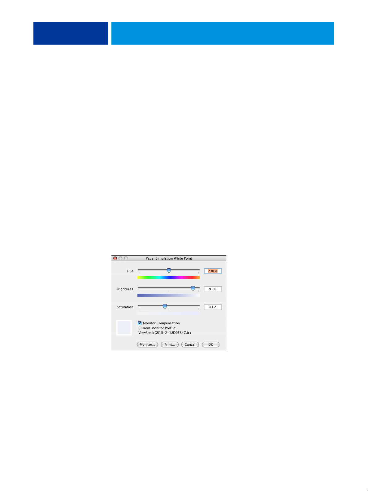
Paper Simulation White Point dialog box
The Paper Simulation White Point dialog box displays Hue, Brightness, and Saturation
sliders. A graphic under each slider displays the current setting. To adjust the settings, drag the
slider left or right, or type a value in the editable text field to the right of the slider bar.
NOTE: The sliders do not show absolute values. The slider position and associated values are
relative to the paper white definition in effect when you open the dialog box.
Hue
This setting allows you to change the hue of the Paper Simulation White Point. Specify a
value between 0.0 and +359.9. If you specify a value greater than 359.9, it automatically
changes to 359.9. If you specify a value less than 0.0, it automatically changes to 0.0.
Page 15

PAPER SIMULATION WHITE POINT EDITING 15
Brightness
This setting allows you to change the brightness of the Paper Simulation White Point.
Specify a value between 0.0 and 100.0 (inclusive). If you specify a value greater than 100.0,
it automatically changes to 100.0. If you specify a value less than 0.0, it automatically changes
to 0.0.
Saturation
This setting allows you to change the saturation of the Paper Simulation White Point.
Specify a value between 0.0 and 100.0 (inclusive). If you specify a value greater than 100.0,
it automatically changes to 100.0. If you specify a value less than 0.0, it automatically changes
to 0.0.
Preview
This area in the lower-left corner of the dialog box displays a preview of the paper simulation
color, surrounded by a white border for contrast. The preview is based on the monitor profile
you specified next to Current Monitor Profile.
To preview the color correctly with your monitor, select the Monitor Compensation option,
and then select the correct monitor profile for your monitor. For more information, see
page 18.
NOTE: To display the colors correctly with your monitor, you must set the monitor and
monitor settings correctly. For more information, see page 12.
Editing Paper Simulation White Point
To edit a custom profile, do the following:
• Select a CMYK Simulation Profile.
• Select Full (Output GCR) for a simulation method.
• Link the simulation profile to an output profile.
Use the following procedure to access the Paper Simulation White Point dialog box to edit
the values.
NOTE: If Paper Simulation is set to On, and you have defined a substitute color as
C=0, M=0, Y=0, K=0, the values defined in Substitute Colors override those for Paper
Simulation. For information about Substitute Colors, see Color Printing.
Page 16

1 Select Simulation
PAPER SIMULATION WHITE POINT EDITING 16
TO ACCESS THE PAPER SIMULATION WHITE POINT DIALOG BOX
1 Start ColorWise Pro Tools and connect to the EX8002.
Start ColorWise Pro Tools from a stand-alone application or Command WorkStation, at
your computer or the monitor connected to the EX8002.
2 Click Color Editor.
3 Select Simulation from the View list.
1
NOTE: You can edit the white point values of simulation profiles only. You cannot edit those of
output profiles.
4 Select a simulation profile and click Select.
The Color Editor dialog box appears.
Page 17
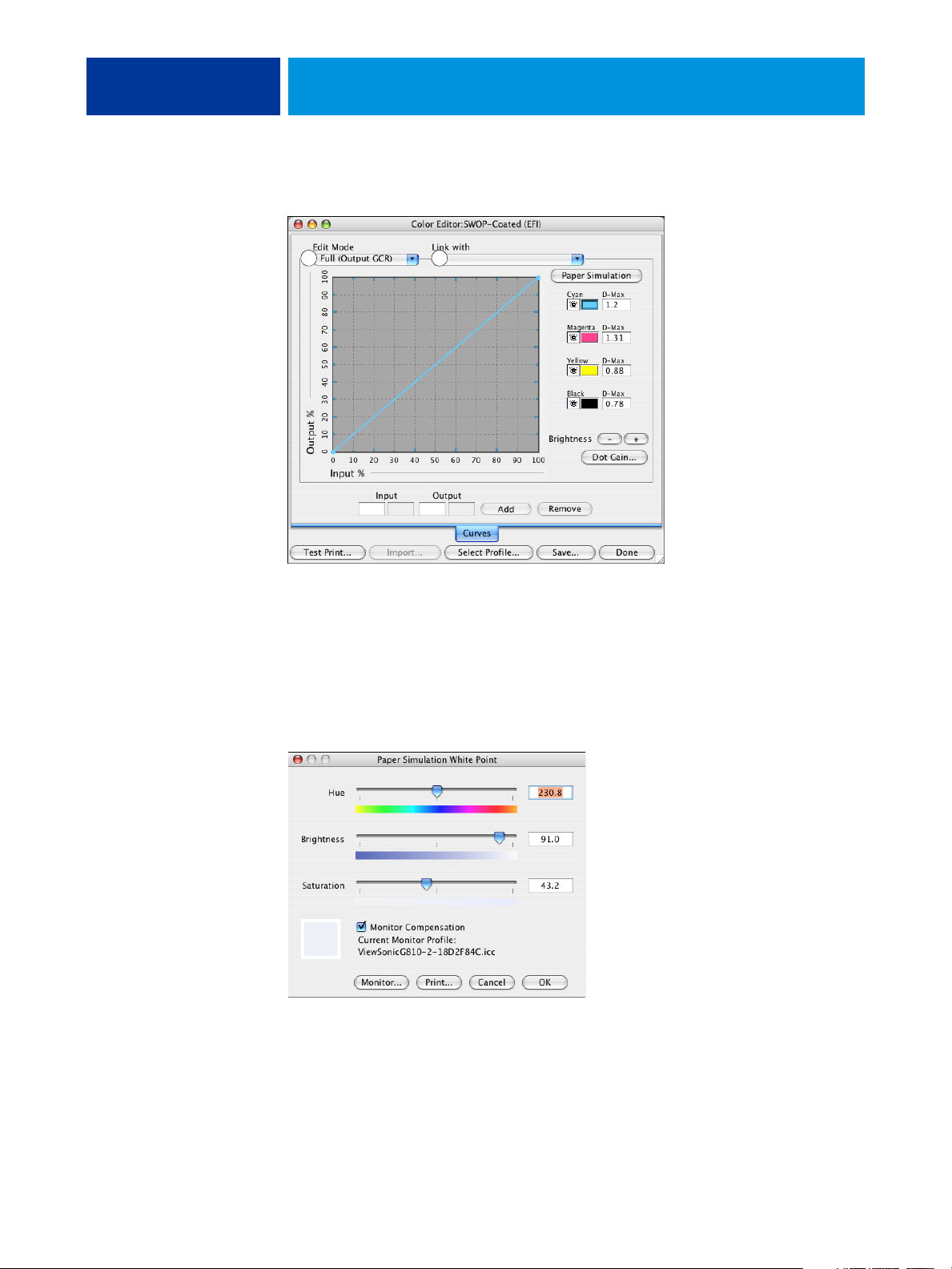
1 Select Full (Output GCR)
2 Output profile name
PAPER SIMULATION WHITE POINT EDITING 17
5 Select Full (Output GCR) in the Edit Mode menu.
1 2
6 Select an output profile to link to the edited simulation profile.
NOTE: When you print a job with the edited simulation profile, you must select the same
output profile you linked to here to realize the effect of the Paper Simulation White Point
editing.
7 Click Paper Simulation.
The Paper Simulation White Point dialog box appears.
Use the following procedure to edit the Paper Simulation White Point values.
Page 18

PAPER SIMULATION WHITE POINT EDITING 18
TO EDIT PAPER SIMULATION WHITE POINT VALUES
1 Select the Monitor Compensation option in the Paper Simulation White Point dialog box.
2 Make sure that the correct monitor profile for your monitor is displayed next to Current
Monitor Profile.
3 If the correct monitor profile is not selected, click Monitor.
The Select Monitor Profile dialog box appears.
4 Select ICC Profiles from the Format list.
5 Select the monitor profile for your monitor and click Open.
The Paper Simulation White Point dialog box appears.
6 Edit the Hue, Brightness, and Saturation values.
Edit the values by dragging the sliders or typing values in the text fields. For detailed
information about the Paper Simulation White Point dialog box, see page 14.
7 View the changes in the preview patch in the lower-left corner of the dialog box.
8 Click Print.
The Print Test dialog box appears.
9 Select settings from the Paper Size and Input Tray lists and click Print.
Page 19

PAPER SIMULATION WHITE POINT EDITING 19
10 Click OK to close the Paper Simulation White Point dialog box.
11 Click Save in the Color Editor dialog box.
The Save dialog box appears.
12 Type a new name and click Save.
13 Quit Color Editor.
Printing with custom paper simulation values
After you edit the paper simulation values in Color Editor, you can print a document with the
custom paper simulation values from the printer driver. You can also override the setting with
Command WorkStation.
NOTE: The procedures for printing a job from a Windows or Mac OS computer are
fundamentally the same. The following procedure uses illustrations from a Mac OS computer.
Use the following procedure to print a job with the custom paper simulation values.
TO PRINT A JOB WITH EDITED PAPER SIMULATION VALUES
1 Choose Print in your application.
The print dialog box appears.
2 Mac OS X v10.5 only: Expand the dialog box, if necessary, by clicking the arrow next to the
Printer name.
3 Mac OS X v10.3.9 and 10.4.x: Choose ColorSync from the drop-down list, and then choose In
Printer from the Color Conversion list.
Mac OS X v10.5: Choose Color Matching from the drop-down list and select In Printer.
4 Choose Fiery Features from the drop-down list.
Page 20

PAPER SIMULATION WHITE POINT EDITING 20
5 Select Two-Way Communication.
For information about enabling Two-Way Communication, see printer driver Help.
6 Click Full Properties, and then click the Color icon.
The Color pane appears.
Page 21

PAPER SIMULATION WHITE POINT EDITING 21
7 Click Expert Settings.
The ColorWise Expert Settings dialog box appears.
8 Select the custom simulation profile from the CMYK Simulation Profile list.
Select the simulation profile that you saved after editing the Paper Simulation White Point
values in the previous section.
9 Select the Full (Output GCR) option.
10 Select Paper Simulation.
11 Select the output profile that you linked to the custom simulation profile from the Output
Profile menu.
12 Click OK.
The Color pane reappears.
13 Click OK.
The job is printed using your custom CMYK Simulation Profile with the edited White Point
values.
Page 22

SPOT-ON WITH TWO-COLOR PRINT MAPPING 22
SPOT-ON WITH TWO-COLOR PRINT MAPPING
In addition to managing “named” colors, Spot-On allows you to assign spot colors and
process colors to the generic colors that are used in a job. The Two-Color Print Mapping
feature is designed for print shop operators to do the proofing for a two-color press. You can
print a two-color job to a two-color device by mapping the colors in a job to the colors that
are already created on the device.
For information about managing named colors with Spot-On, see Color Printing.
NOTE: The RGB colors in a document are first converted to CMYK colors and then the
Two-Color Print Mapping is applied.
The following limitations apply when you use the Two-Color Print Mapping feature:
• The settings for Two-Color Print Mapping are ignored when the Composite Overprint
and Combine Separation features are enabled.
• Postflight does not report on Two-Color Print Mapping, because Postflight reports the
source state of a document. The color space that the digital press receives before any
conversions is reported in Postflight.
• You cannot select the Two-Color Print Mapping and Substitute Color options at the same
time. Also, you cannot select a substitute color to be used in the Two-Color Print Mapping
feature.
Using Two-Color Print Mapping
In the Two-Color Print Mapping feature, the colors that are used in a job are mapped with the
colors to print. From the Spot-On main window, open the Define Two-Color Print Map
dialog box and then reassign the document colors to the named or custom colors to print
with. When the feature is turned on from the printer driver, EX8002 replaces the document
colors with the colors you defined in the Define Two-Color Print Map dialog box. You can
also override the print option setting using Command WorkStation.
Page 23

SPOT-ON WITH TWO-COLOR PRINT MAPPING 23
Defining a color for Two-Color Print Mapping
Use the following procedure to define the color mappings in the Two-Color Print Map
dialog box.
TO DEFINE A COLOR FOR TWO-COLOR PRINT MAPPING
1 Start ColorWise Pro Tools and connect to the EX8002.
Start ColorWise Pro Tools from a stand-alone application or Command WorkStation, at your
computer or at the monitor connected to the EX8002.
2 Click Spot-On.
The Select Output Profile dialog box appears.
3 Select an output profile and click OK.
The Spot-On main window appears.
NOTE: The 2-Color Print Mapping group always appears at the top of the list.
It is not included in the priority arrangements.
4 Double-click 2-Color Print Mapping.
The two colors for mapping appear.
Page 24

SPOT-ON WITH TWO-COLOR PRINT MAPPING 24
5 Double-click one of the color lines.
The Define Two-Color Print Map dialog box appears.
The document colors on the left side represent the colors that are used in a job. Map these
colors to the named or process colors that you select on the right. Initially, Black and Magenta
appear as placeholder colors on the left.
NOTE: When you change the color selection on the left, the selection on the right changes to
Process Color with the same color name. This is to avoid accidentally mapping a color to a
different process color.
6 Select a process color from the Print list on the left.
Select Cyan, Magenta, Yellow, or Black.
7 Select Named Color Group or Process Color on the right.
To select a named color, continue the steps. To select a process color, go to step 10.
8 Select a group from the Named Color Group list.
Select from the list of the named color groups that are already defined in Spot-On.
The prefix of the selected group appears on the left side of the Named Color field. The suffix
appears on the right side of the field.
9 Type the name of the named color in the Named Color field.
NOTE: The names are case sensitive. Type the name exactly as it appears in the list in Spot-On.
If the name you typed in the Named Color field is invalid, the EX8002 displays an error
message.
NOTE: If the Named Color Group option is selected and the Named Color field is not filled,
the EX8002 displays an error message. Type a name in the Named Color field or select the
Process Color option instead of the Named Color Group.
Page 25

SPOT-ON WITH TWO-COLOR PRINT MAPPING 25
10 Select Cyan, Magenta, Yellow, or Black from the Process Color list.
11 Repeat steps 6 through 10 for the other color to map.
NOTE: You cannot select the same process color for both document colors. When a process
color is selected for a document color, it is grayed out for the other document color.
12 When you are done selecting the colors, click OK to close the dialog box.
13 Choose File > Save (or click the Save icon).
The changes in the Define Two-Color Print Map are saved and the newly assigned mapping
colors and values appear in the Spot-On main window.
Printing a job with Two-Color Print Mapping
After you map the colors in the Two-Color Print Map dialog box in Spot-On, you can print
a two-color job from the printer driver. You can also override the print option setting using
Command WorkStation.
NOTE: When you print a job, select the same output profile from the printer driver as the one
that was selected in the Select Output Profile dialog box. Otherwise, print mappings that are
defined in Spot-On have no effect.
NOTE: The procedures for printing a job from a Mac OS and a Windows computer
are similar.
TO PRINT A TWO-COLOR JOB
1 Open a document in your application.
2 Choose Print.
3 Mac OS X v10.5 only: Expand the dialog box, if necessary, by clicking the arrow next to the
Printer name.
4 Mac OS X v10.3.9 and 10.4.x: Click Copiers & Pages and choose Fiery Features from the drop-
down list.
Mac OS X v10.5: Click Preview and choose Fiery Features from the drop-down list.
Page 26

SPOT-ON WITH TWO-COLOR PRINT MAPPING 26
5 Click Full Properties, and then click the Color icon.
The Color pane appears.
6 Select 2-Color Print Mapping.
7 Click OK.
The job is printed with the mapping you defined in Spot-On.
Page 27

COLOR SETUP FEATURES 27
COLOR SETUP FEATURES
With Fiery Graphic Arts Package, Premium Edition, ColorWise Pro Tools Color Setup offers
the following customizable features, in addition to the Color Process Flow feature:
• Control Bar
•Auto Trapping
•Progressives
•Halftone Simulation
For information about Color Process Flow, see Color Printing.
NOTE: The ColorWise Pro Tools applications for Windows and Mac OS computers
are similar.
ColorWise Pro Tools Color Setup features
Access the Control Bar, Auto Trapping, Progressive, and Halftone Simulation features from
Color Setup.
For information about these features, see the following sections:
• Control Bar (see page 29)
• Auto Trapping (see page 36)
• Progressives (see page 42)
• Halftone Simulation (see page 46)
Page 28

COLOR SETUP FEATURES 28
Using Color Setup
Use the following procedure to start Color Setup.
NOTE: For information about installing ColorWise Pro Tools and configuring a connection,
see Color Printing.
TO START COLOR SETUP
1 Start ColorWise Pro Tools and connect to the EX8002.
NOTE: Start ColorWise Pro Tools from a stand-alone application or Command WorkStation,
at your computer or the monitor connected to the EX8002. At Command WorkStation,
choose Manage Color from the Server menu.
2 Click Color Setup.
The Color Setup main window appears with the Color Process Flow tab selected.
Page 29

Control Bar
COLOR SETUP FEATURES 29
Control Bar allows you to add a static color bar and dynamic job information to each printed
page at the user-defined location. The feature can be set as a server default or overridden on a
per-job basis.
The default Control Bar is designed to fit the EX8002 default paper size, Letter/A4, or larger.
You can create Control Bars for other paper sizes.
NOTE: If a Control Bar does not fit on the page, it will be clipped.
NOTE: If a background color is defined as “white” for a user-defined Control Bar, it must be
defined in the CMYK color space for the Paper Simulation feature to take effect. For more
information about Paper Simulation, see page 13.
Control Bar workflow
The default Control Bar provides a color bar and dynamic job information. Print a job with
the default Control Bar by setting the Control Bar print option to On from the printer driver.
Many jobs print satisfactorily with the default Control Bar, but if you require your own color
bars, create them by defining custom values in the Control Bar Definition dialog box. After
you define a custom Control Bar in the Control Bar pane in Color Setup, you can print a job
with the custom Control Bar from the printer driver.
To print a job with the default Control Bar, see the following section. For information about
the Control Bar pane, see page 31. To create your own Control Bars, see page 32. To print a
job with a custom Control Bar, see page 36.
Printing with the default Control Bar
Print a job with the default Control Bar by setting the Control Bar print option to On from
the printer driver.
Page 30

COLOR SETUP FEATURES 30
TO PRINT A JOB WITH THE DEFAULT CONTROL BAR
1 Choose Print from your application.
2 Select EX8002 as your printer and click Properties.
The Properties dialog box appears, with the Fiery Printing tab selected.
3 Click the Job Info icon.
4 Select Control Bar.
1 Job information
2 Static color bar
5 Click OK.
6 Click Print.
The job is printed with the default Control Bar.
2
1
Page 31

COLOR SETUP FEATURES 31
Control Bar pane
Access the Control Bar pane by clicking the Control Bar tab in the ColorWise Pro Tools
Color Setup dialog box (see page 32).
The Control Bar tab allows you to do the following:
• Set the Print Control Bar option to On (see the following section).
• View the definition of a Control Bar (see page 32).
• Define a new Control Bar (see page 32).
• Edit a Control Bar (see page 35).
• Duplicate a Control Bar (see page 35).
• Delete a Control Bar (see page 35).
• Restore the factory default values (see page 36).
Setting the Print Control Bar option to On
Selecting the Print Control Bar option sets the Printer’s Default value to On. If this option
is selected, a Control Bar is printed on all pages sent to the EX8002 when Printer’s default is
selected from the printer driver or with Command WorkStation.
Page 32

COLOR SETUP FEATURES 32
Viewing the definition of a Control Bar
Selecting a Control Bar in the Available Control Bar list allows you to view the settings
information in the Control Bar Definition area. With this feature, you can identify the
Control Bar without opening the Control Bar Definition dialog box.
The following information is displayed in the Control Bar Definition area:
• Color Bar EPS File
• Job Information
• Text Location
• Distance from edge
Defining a new Control Bar
When you open the Control Bar pane for the first time, only the default Control Bar is
available in the Control Bar Definition dialog box. You can create a custom Control Bar that
better fits your needs.
Use the following procedure to access the Control Bar pane and create a new Control Bar.
TO CREATE A CUSTOM CONTROL BAR
1 Start ColorWise Pro Tools and connect to the EX8002.
2 Click Color Setup.
3 Click the Control Bar tab.
4 Click New in the Control Bar pane.
The Control Bar Definition dialog box appears.
5 Define the values for each option.
For information about Control Bar options, see “The Control Bar Definition dialog box” on
page 33.
6 Click OK.
A custom Control Bar is created.
Page 33
COLOR SETUP FEATURES 33
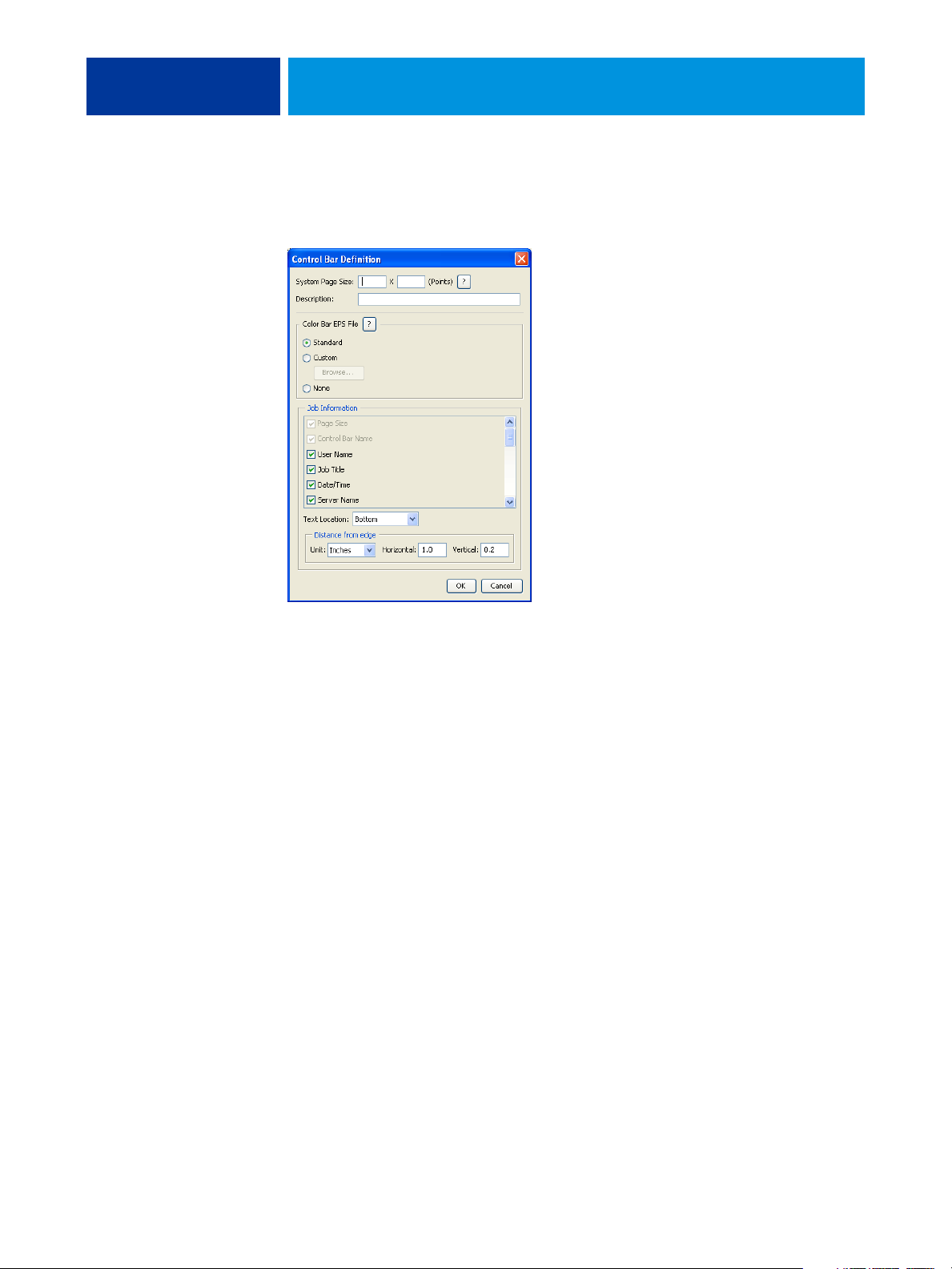
The Control Bar Definition dialog box
The explanation of each section in the Control Bar Definition dialog box is as follows:
NOTE: The Control Bar Definition dialog box is displayed when you click New in the
Color Setup dialog box.
NOTE: Each field of this dialog box initially displays the value from the Control Bar that is
currently set as default, except for the System Page Size.
•
System Page Size: A System Page Size label with two numbers is printed with each Control
Bar. These numbers are the exact numbers to enter when creating a custom Control Bar.
Every page produced by the EX8002 has a System Page Size. These two numbers represent
the width and height of the page, in points, as processed by the system. Page sizes that are
not defined use the Default system Control Bar.
To find the System Page Size for a job, see a previously printed Control Bar on a document
using the targeted paper size and orientation.
•
Description: This field allows you to add a one-line description of the custom Control Bar
for your future reference.
•
Control Bar EPS File: This option allows you to select the following:
– Standard: (provided as a default)
– Custom: (user-designed EPS)
– None: (no EPS file is required)
The EPS file contains a color bar and any logo or static information that you want to
include on the page.
Page 34

COLOR SETUP FEATURES 34
• Job Information: The options vary, but typically the following information is available, in
addition to the print options that you specify in the Color pane from the printer driver:
–Page Size
– Control Bar Name
–User Name
–Job Title
–Date/Time
–Server Name
–Printer
– Calibration Date/Time
–Output Profile
–Notes
– Instructions
•
Text Location: This list allows you to select the location in which you want the job
information printed on the page:
– Bottom
–Left
–Top
–Right
For the location and orientation of the job information, see the following illustration.
Top
Left
Right
Bottom
Page 35

COLOR SETUP FEATURES 35
• Distance from the edge: This text field allows you to define the distance from the
lower-left corner at which you want the job information to begin printing. The settings to
define are as follows:
–
Units: Select inches, millimeters, or points from the Units list.
–
Horizontal: Type the value.
–
Vertical: Type the value.
Editing a Control Bar
You can edit all of the values in the Control Bar Definition dialog box, with the exception of
System Page Size, which appears dimmed.
The System Page Size for the default Control Bar refers to different system page sizes.
For other Control Bars, values are displayed in the text field.
NOTE: To display the Control Bar Definition dialog box for editing, select a Control Bar in
the Available Control Bar list, and then click Edit.
Duplicating a Control Bar
When you duplicate a Control Bar, all the values of the original Control Bar are displayed.
You can edit and save the duplicate as a custom Control Bar.
If you edit and save a Control Bar as a custom Control Bar, you must change the System Page
Size values. No two Control Bars can use the same values. If you try to save the custom
Control Bar without changing the System Page Size values, a warning message appears.
Because a Control Bar is not a part of a job, a document can be printed with one Control Bar
and then with another one if the Control Bar definition has changed. To keep the Control Bar
and reuse it later, you must save the changes as a custom Control Bar.
NOTE: To display the Control Bar Definition dialog box for duplicating, select a Control Bar
in the Available Control Bar list and click Duplicate.
Deleting a Control Bar
You can delete a Control Bar from the list in the Available Control Bar dialog box. You are
prompted to confirm the deletion.
NOTE: You cannot delete the default Control Bar.
Page 36

COLOR SETUP FEATURES 36
Restoring the factory default values
The Control Bar Definition dialog box allows you to delete all user-defined Control Bars and
restore the default Control Bar to its original state by clicking Factory Defaults.
Printing with a custom Control Bar
The procedure to print a job with a custom Control Bar is basically the same as to print with
the default Control Bar (see page 29). Use the following procedure to print with a custom
Control Bar.
TO PRINT A JOB WITH A CUSTOM CONTROL BAR
1 Choose Print from your application.
2 Select EX8002 as your printer and click Properties.
The Properties dialog box appears with the Fiery Printing tab selected.
3 Click the Job Info icon.
4 Select On from the Control Bar list.
NOTE: Selecting On from the printer driver affects the current job only. If you selected Print
Control Bar in the Control Bar pane, selecting Printer’s Default has the same effect as On.
Selecting Print Control Bar in the Control Bar pane sets the default value to On for all jobs.
5 Click OK.
6 Click Print.
The job is printed with the Control Bar specified in the Control Bar Definition dialog box.
Configurable Auto Trapping
Trapping is a technique where some objects are printed slightly larger or smaller than you have
specified in an application, in order to prevent white edges around the objects. These white
edges, or “halos,” can be caused by factors such as misregistration, the physical properties of
the toners, and the stiffness of the media.
The configurable Auto Trapping feature provides you with advanced trapping settings and
gives you full control over their values. The EX8002 is shipped with values that are optimized
for the print device using regular paper, but if these values do not provide the results necessary
for the media that you use, modify the values to meet your requirements.
Page 37

COLOR SETUP FEATURES 37
Configurable Auto Trapping workflow
The fixed values are set as default for Auto Trapping. The EX8002 applies these fixed values
when you set Auto Trapping to On, with generally good results. However, to customize the
values for Auto Trapping, define the values in the Auto Trapping pane in Color Setup. After
you define the values, print a job with Auto Trapping set to On from the printer driver.
Printing with default Auto Trapping
You can print a job with default Auto Trapping by setting the Auto Trapping print option to
On from the printer driver.
TO PRINT A JOB WITH DEFAULT AUTO TRAPPING
1 Choose Print from your application.
2 Select EX8002 as your printer and click Properties.
The Properties dialog box appears with the Fiery Printing tab selected.
3 Click the Color icon.
4 Select On from the Auto Trapping list.
5 Click OK.
6 Click Print.
The job is printed with the default Auto Trapping values.
Page 38

COLOR SETUP FEATURES 38
Auto Trapping pane
Access the Auto Trapping pane by clicking the Auto Trapping tab in the ColorWise Pro Tools
Color Setup dialog box (see page 41).
The settings in the Auto Trapping pane allow you to perform the following tasks:
• Set the Apply Auto Trapping option to On (see the following section).
• Specify the trap width (see page 39).
• Specify the trap color reduction (see page 39).
• Specify the trap shape (see page 40).
• Specify the trap object types (see page 40).
• Restore the factory default values (see page 40).
Page 39

COLOR SETUP FEATURES 39
Setting the Apply Auto Trapping option to On
When you select the Apply Auto Trapping option, you set the Printer’s default value to On.
When you select Printer’s default from the printer driver, the configured auto trapping is
applied to the job sent to the EX8002.
Specifying Trap Width
Trap Width values determine how thick the trapped areas are. Specify the following values:
•
Horizontal: Defines the horizontal thickness of the trapped areas (0-10 pixels).
•
Vertical: Defines the vertical thickness of the trapped areas (0-10 pixels).
When you select the Uniform option, the horizontal and vertical Trap Width values are the
same. If the values were set before you selected Uniform, the higher of the two values is used
for both.
A small bitmap image in the lower-left corner of the Trap/Width pane provides a dynamic
visual example of the selected values.
Specifying Trap Color Reduction
Trap Color Reduction values determine how intense the trapping effect is. The values entered
reflect the percent reduction of the toner in the trap. You can enter values for the following
color channels:
•
Cyan: Defines the trap reduction in cyan (0-100%).
•
Magenta: Defines the trap reduction in magenta (0-100%).
•
Yellow: Defines the trap reduction in yellow (0-100%).
•
Black: Defines the trap reduction in black (0-100%).
A 100% reduction results in no toner intensity applied to the trap. A 0% reduction results in
full toner intensity.
When you select the Uniform option, all four Trap Color Reduction values are the same.
If the values were set before you selected Uniform, the highest value is used for all.
A small bitmap image to the left of each color in the Trap Color Reduction pane provides
dynamic visual examples of the selected values.
Page 40

COLOR SETUP FEATURES 40
Specifying Trap Shape
Trap Shape represents how a single pixel appears when trapped against a contrasting
background. With elements bigger than one pixel, the shape, or part of the shape, is only
visible at the corners of objects. Select any of the following shapes:
• Ellipse
•Diamond
•Rectangle
Specifying Trap Object Types
When no option is selected in the Trap Object Types area, only trapping of objects (text and
graphics) against objects is applied. Select any of the following:
•
Trap Objects to Images: Auto trapping is applied to boundary areas between objects
and images.
•
Trap Images Internally: Auto trapping is applied to every individual pixel of an image.
This option is available only when you select Trap Objects to Images. If the Trap Objects
to Images option is cleared, the Trap Images Internally option appears dimmed.
Restoring factory defaults
Click Factory Defaults to delete all user-defined settings for Auto Trapping and restore the
factory default settings.
Page 41

COLOR SETUP FEATURES 41
Defining custom values for Auto Trapping
Use the following procedure to select the Auto Trapping settings and define custom values.
TO DEFINE AUTO TRAPPING VALUES
1 Start ColorWise Pro Tools and connect to the EX8002.
2 Click Color Setup.
3 Click the Auto Trapping tab.
4 Define a value for each option in the Auto Trapping pane.
For information about the options in the Auto Trapping pane, see page 38.
5 Click Apply.
The defined Auto Trapping values are applied.
Printing with the configurable Auto Trapping feature
After you define the Auto Trapping values, print a job with the Auto Trapping feature by
setting the Auto Trapping print option to On from the printer driver. You can change the
setting for this print option using Command WorkStation.
NOTE: If the Auto Trapping values are changed, reRIPping is required to print a job with the
new values.
Use the procedure on page 30 to print a job with custom Auto Trapping values from the
printer driver.
NOTE: Selecting On from the printer driver affects the current job only. Selecting Apply Auto
Tr a p p i n g i n t he Au t o Tr app in g p an e in C ol or Setup sets the default value for all jobs, and
allows you to select Printer’s default from the printer driver.
The job is printed with the Auto Trapping values defined in the Auto Trapping pane.
Page 42

Progressives
COLOR SETUP FEATURES 42
The term “Progressives” refers to printing variations in a multi-color document.
The variations may use from one to all of the available color channels in a print device.
The majority of printing processes that involve more than one or two colorants apply the
colorants sequentially. Traditionally, progressives are the intermediate states after some and
before all colorants have been applied. The Progressives feature is more flexible, because it
allows you to select which color is printed, using up to four sheets per original document
page.
NOTE: The Progressives feature is designed to show you the toner separations used by
the job on the print device. The feature is not intended to be used to proof for another
non-Fiery driven print device.
NOTE: Progressives show the separations that the EX8002 sends to the print device, not the
separations contained in the job source file.
NOTE: Progressives is a “reporting” feature. It is not designed to be used with production
features such as VDP and Imposition. Progressives is offered for diagnostic situations. With
high volume applications or production environments, use Progressives only on the
individual pages that need testing.
Progressives workflow
You can inspect the result of each channel with the default values for color channels in
Progressives. However, if you must customize the selection of color channels or number of
sheets to print, you can do so by specifying the color channels in the Progressives pane in
Color Setup. After specifying the color channels, print a job with the customized Progressives
by setting the print option to On from the printer driver.
NOTE: You cannot use the Progressives and Postflight features at the same time. A constraint
is set for these print options from the printer driver.
NOTE: Clearing plates in ImageViewer does not have an effect on a Progressives job printed
from ImageViewer. It prints with the values specified in the Progressives pane. For more
information, see “ImageViewer” on page 53.
Page 43

COLOR SETUP FEATURES 43
Printing with the default Progressives
Print a job with the default Progressives by setting the Progressives print option to On from
the printer driver.
TO PRINT A JOB WITH THE DEFAULT PROGRESSIVES
1 Choose Print from your application.
2 Select EX8002 as your printer and click Properties.
The Properties dialog box appears with the Fiery Printing tab selected.
3 Click the Job Info icon.
4 Select Progressives.
5 Click OK.
6 Click Print.
The job is printed with the default Progressives.
Page 44

COLOR SETUP FEATURES 44
Progressives pane
Access the Progressives pane by clicking the Progressives tab in ColorWise Pro Tools
Color Setup. For more information about accessing the pane, see the procedure on page 49.
The settings in the Progressives pane allow you to do the following:
• Specify sheets (1-4) and colors per sheet to print (see the following section).
• Restore the factory default values (see page 45).
Specifying sheets and colors
At least one colorant (Cyan, Magenta, Yellow, or Black) must be selected for each sheet and at
least one sheet must be selected.
Small bitmap images to the left of each row dynamically change to reflect your selections.
Page 45

COLOR SETUP FEATURES 45
Restoring factory defaults
Clicking Factory Defaults allows you to delete all user-defined settings for the Progressives
feature and restore the default settings.
Factory default values are set as follows:
• Sheet 1: Black
• Sheet 2: Black + Cyan
• Sheet 3: Black + Cyan + Magenta
• Sheet 4: Black + Cyan + Magenta + Yellow
These selections are arbitrary, independent of the source job and the printing order of the
digital press. With this selection, the first sheet includes the black plate only, because it is
often the most important plate when looking at separations. The other colors are added in a
“progressive” order.
When you return to the Progressives tab, the set of selections you last made is displayed.
The colors included do not have to represent the actual sequence applied by the digital press,
which provides more flexibility for analyzing the image composition.
Specifying color channels
Use the following procedure to access the Progressives pane and specify color channels.
TO ACCESS THE PROGRESSIVES PANE AND SPECIFY COLOR CHANNELS
1 Start ColorWise Pro Tools and connect to the EX8002.
2 Click Color Setup.
3 Click the Progressives tab.
4 Specify the color channels in the Progressives pane.
For information about the options in the Progressives pane, see page 44.
5 Click Apply.
The specified color channels are applied.
Page 46

COLOR SETUP FEATURES 46
Printing with custom Progressives
After specifying the color channels, print a job with custom Progressives by setting the
Progressives print option to On from the printer driver.
NOTE: Alternatively, you can send a job with the default Progressives setting and change the
print option setting using Command WorkStation.
Use the same procedure on page 43 to print a job with the custom Progressives feature from
the printer driver. The printed job reflects the Progressives settings you defined in the
Progressives pane.
Halftone Simulation
When proofing, we recommend that you print in contone mode, which uses the best color in
the EX8002 system. For advanced proofing purposes, Graphic Arts Package, Premium
Edition offers user-controlled halftone generation. Halftoned proofs simulate, with reasonable
accuracy, the final dots imaged on films or plates for offset printing. The halftone screening
feature allows you to define the custom screening functions applied to your print job.
Halftone Simulation workflow
You can select pre-set halftone screens to print jobs with good results. When you must
customize the values for a halftone screen, define a custom halftone in your application or at
Color Setup, and then select the screen in the Halftone Simulation
printer driver.
For information about the print option and the procedure to print with the pre-defined
halftone screens, see the following section. For information about the Halftone Simulation
pane and the procedure to specify custom halftone screen values, see page 48.
print option from the
Halftone Simulation print option
Access the halftone screening feature through the Halftone Simulation print option. Select
from the following option items:
•
Application Defined: Uses a pre-defined halftone screen specified in an application.
For information about the supported applications, see page 50.
•
Newsprint: Uses a pre-defined halftone screen that looks and feels like a newspaper.
•
User Defined Screen1/2/3: Applies a user-defined halftone screen based on the settings in
ColorWise Pro Tools Color Setup.
NOTE: Use Newsprint and User Defined Screen1/2/3 with all applications, including
Microsoft Office.
Page 47
COLOR SETUP FEATURES 47
Printing with pre-defined halftone screens
Use the following procedure to print a job with a pre-defined default halftone screen from the
printer driver.
TO PRINT A JOB WITH A DEFAULT HALFTONE SCREEN
1 Choose Print from your application.
2 Select EX8002 as your printer and click Properties.
The Properties dialog box appears with the Fiery Printing tab selected.
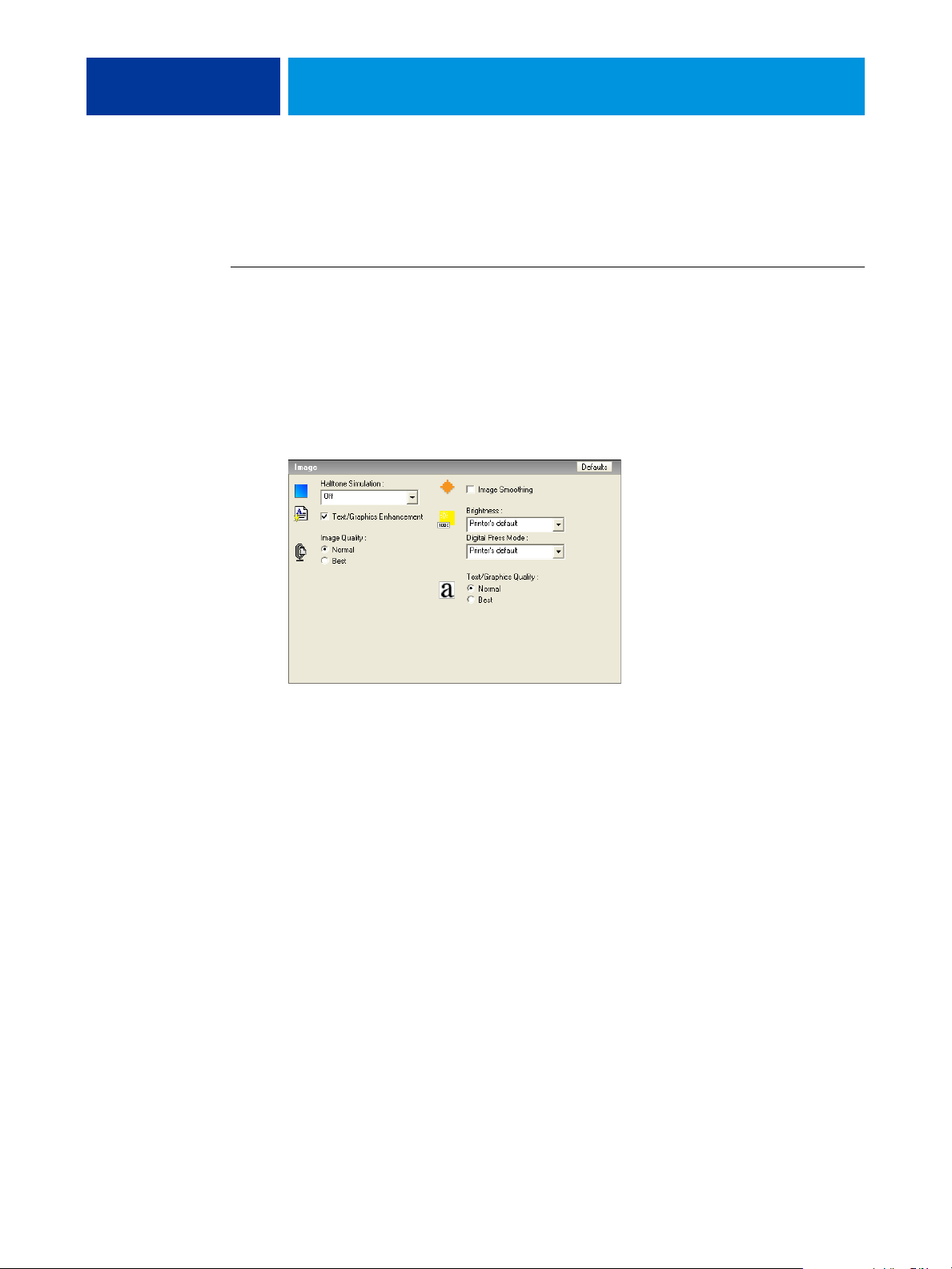
3 Click the Image icon.
4 Select a pre-defined halftone screen from the Halftone Simulation list.
For more information, see page 46.
5 Click OK to close the Properties dialog box.
6 Click Print.
The job is printed to the EX8002 with the pre-defined halftone screen.
Page 48

COLOR SETUP FEATURES 48
Halftone Simulation pane
You can define three custom halftone screens on the Halftone Simulation pane.
For each of these screens, you can define the following values:
Angle
Type a number (from 0-360) for each color: Cyan, Magenta, Yellow, and Black.
Frequency (LPI)
Type a number for each color: Cyan, Magenta, Yellow, and Black. Select the check box
next to the link icon to make the values for Frequency (LPI: lines per inch) the same for
all four channels. Frequency refers to the number of rows of spots that combine to form a
halftone dot.
Page 49

COLOR SETUP FEATURES 49
Dot shape
Select a PostScript function for dot shape. When you select Custom, the Dot Shape dialog
box appears. This dialog box provides a text field in which you type a PostScript function.
When this dialog box first opens, it reflects the last custom-defined dot shape.
Setting a custom halftone screen
Use the following procedure to access the Halftone Simulation pane and specify a custom
halftone screen.
TO SPECIFY A CUSTOM HALFTONE SCREEN
1 Start ColorWise Pro Tools and connect to the EX8002.
2 Click Color Setup.
3 Click the Halftone Simulation tab.
4 Specify the angle, frequency, and dot shape for a custom halftone screen.
For information about the options on the Halftone Simulation pane, see page 48.
5 Click Apply.
The specified settings for Angle, Frequency, and Dot Shape are applied to the custom
halftone screen.
Page 50

COLOR SETUP FEATURES 50
Printing with custom halftone screens
After specifying the halftone screen values for User Screen 1, User Screen 2, or User Screen 3,
select a corresponding custom screen name from the printer driver. Use the same procedure
on page 47 to print a job with a custom halftone screen.
NOTE: Alternatively, you can send a job with a default halftone screen and change the print
option setting using Command WorkStation.
The printed job reflects the settings you defined on the Halftone Simulation pane.
Supported applications
The following applications have been tested with Mac OS and Windows for compatibility
with the Application Defined setting in the Halftone Simulation print option. Other
applications should work as well, as long as they are using standard PostScript conversions on
halftone screen definitions and the parameters used in the definitions are kept within the
physical limitations of the digital press.
• Adobe Acrobat
• Adobe Illustrator
• Adobe InDesign
• Adobe PageMaker
• Adobe FreeHand
• QuarkXPress
Page 51

COLOR SETUP FEATURES 51
Calibrating for custom halftone screens
When color quality is important, make sure that the EX8002 is calibrated for the particular
halftone screen that you use. Changing a halftone screen usually modifies the color response
of the digital press.
The best color is achieved when an Output profile that is associated with the appropriate
calibration response is selected at print time. However, when custom halftones are specified,
the EX8002 does not have adequate information about the resulting color response. For this
reason, achieving good color with custom halftone screens is often possible only when you
perform custom halftone calibration and use a profile based on this custom halftone.
Use the following procedure to calibrate the EX8002 for custom halftone screens.
TO CALIBRATE THE EX8002 FOR CUSTOM HALFTONE SCREENS
1 Prepare the measurement instrument you use for calibration.
2 On the User Software DVD, open the folder that contains the custom halftone calibration
files.
The folder locations for Mac OS and Windows are as follows:
Mac OS: Mac Color Files: Calibration Files:Halftone Calibration Files:Photoshop or Other
Applications
Windows: Windows Color Files\Calibration Files\Halftone Calibration Files\Photoshop or
Other Applications
The folder contains images of the measurement pages for various instruments and page sizes.
If you print halftone screens only from Adobe Photoshop, open the Photoshop folder.
Otherwise, open the Other Applications folder.
NOTE: When opening or printing these files, never “color-manage” using PostScript Color
Management or ICC profiles that provide color conversions.
3 From Photoshop, open the image file that corresponds to your instrument and page size.
From other applications, open a blank document and place the EPS file that matches your
instrument and page size.
The images were prepared for the final sheet page size. If you are placing an image, do so
using no margins. Ignore warnings that the image may be clipped.
NOTE: If you use these measurement pages with the EX8002 standard screens, make sure to
properly set the PPD print option that controls the screen.
Page 52

COLOR SETUP FEATURES 52
4 Print the measurement page using your custom halftone and other print option settings.
This page is now the custom calibration measurement page.
You must print this measurement page with the CMYK Simulation Profile print option set to
ColorWise Off, which produces an uncalibrated page.
NOTE: To calibrate your digital press, you must print CMYK patches in the raw state of the
digital press. Except for the Output Profile print option, the ColorWise print options are
irrelevant and will be ignored. Use the Output Profile setting that corresponds to the type of
paper you are using.
To increase the speed and reliability of the calibration, print your measurement page, with the
appropriate print option settings, to a PostScript file. The next time you calibrate, download
this PostScript file. Retaining this file in the Hold queue of the EX8002 makes the entire
calibration process even faster.
5 Use ColorWise Pro Tools Calibrator to perform the calibration.
NOTE: Do not use the Print button to generate the measurement page in Calibrator. Use the
measurement page that you printed in step 4.
For information about Calibrator, see Color Printing.
Page 53

IMAGEVIEWER
Accessing ImageViewer
IMAGEVIEWER 53
ImageViewer allows you to soft proof and adjust colors in a job before it is printed. You can
use the preview in ImageViewer to verify job placement, orientation, and content, as well as
general color accuracy. If the job contains halftone screened settings, the preview shows a
composite view of all separations at the dot level. You can select to display the plate data for
each process color independently or in combination with the other colors, allowing inspection
of individual plate data or a combination of any range of plates.
Start ImageViewer from the Actions menu or Preview window of Command WorkStation.
TO START IMAGEVIEWER FROM THE ACTIONS MENU
1 In the Active Jobs window of Command WorkStation, select the job that you want to preview.
NOTE: ImageViewer recognizes only jobs that show processed/held (dark yellow) status.
Processed/held jobs are also indicated by the raster job icon (page icon ringed with a halo).
2 If needed, choose Process and Hold from the Actions menu to move the job to processed/
held status.
3 To start ImageViewer, do one of the following:
• Choose Launch EFI ImageViewer from the Actions menu.
• Right-click the selected job and choose Launch EFI ImageViewer from the menu
that appears.
The ImageViewer main window appears.
Page 54

IMAGEVIEWER 54
TO START IMAGEVIEWER FROM THE PREVIEW WINDOW
1 In the Active Jobs window of Command WorkStation, select the job that you want to preview.
NOTE: ImageViewer recognizes only jobs that show processed/held (dark yellow) status.
2 If needed, choose Process and Hold from the Actions menu to move the job to processed/held
status.
3 Choose Preview from the Actions menu.
Page thumbnails appear in the Preview window.
1 Click for full-screen preview
1
4 To start ImageViewer, do one of the following:
• Select the thumbnail of the page that you want to soft proof, and click the Full-Screen
Preview button.
• Double-click the thumbnail of the page that you want to soft proof.
The ImageViewer main window appears.
For information about using the ImageViewer application, see ImageViewer Help.
Page 55

PREFLIGHT
Using Preflight
PREFLIGHT 55
The Preflight feature performs a simple check of the most common areas of error to ensure
that the job will print successfully and to the expected quality on the selected printing device.
This feature is accessible from Command WorkStation. For more information about
Command WorkStation, see Utilities and Command WorkStation Help.
Use the following steps to preflight a job.
TO PREFLIGHT A JOB
1 Select a spooled/held job in the Active Jobs window and choose Actions> Preflight.
2 Set a notification level for each error or use the default Preset.
For more information about setting preflight options, see page 56.
3 Click Save to save the settings as a new preset if you want to use them again.
4 Click Preflight to perform the Preflight check.
5 Click Save to save the report as a PDF.
6 Click Print Report to print the report.
7 Click Preflight Again to repeat the preflight check.
8 Click Close to exit Preflight.
Supported file formats for preflight
The following file formats are supported for preflight:
•PostScript
•PDF
•EPS
•PPML
•Creo VPS
NOTE: TIFF files are not supported for Preflight checks.
Page 56

PREFLIGHT 56
Setting Preflight options
Before performing the preflight check on your job, specify the following preflight checks and
notification levels.
Setting preflight checks
You can set preflight checks for the following:
•
Fonts: When missing and When substituted
•
Spot Colors: When missing
•
Low-Res Images: When image resolution is less than specified dpi
•
VDP Resources: When not found
You can choose to Preflight individual VDP resources.
•
Hairlines: When line width is less than specified point size
•
Overprint: When overprint is detected
•
PostScript: When any PostScript error is found
•
Stop preflight on first error: When any error is found
Setting notification levels
For each preflight category, you can specify a notification level:
•
Critical marks any errors with a Critical icon ( ).
•
Warning marks any errors with a Warning icon ( ).
•
Message marks any errors with a Message icon ( ) and provides information.
•
Ignore skips check of that category.
A category with no errors is marked with a Pass icon ( ).
Page 57

HOT FOLDERS FILTERS 57
HOT FOLDERS FILTERS
This chapter describes how to configure the Hot Folders filters to convert various files
to PostScript or PDF (Portable Document Format), or to preflight certain files.
For information about operating systems that support Hot Folders, see Welcome.
For information about installing the Hot Folders application, see Utilities.
For information about using the Hot Folders application, see Hot Folders Help.
About file conversion
Hot Folders filters allow you to convert certain file formats to PostScript or PDF or to
preflight files for conformity. File conversion and preflighting take place on your computer
within Hot Folders, which saves EX8002 resources. You can print files directly from Hot
Folders filters without starting the application from which they were created.
1 Hot folder with Exclusive
filter (Windows)
2 Standard Hot Folder
(Windows)
3 Hot Folder with Exclusive
filter (Mac OS)
4 Standard Hot Folder
(Mac OS)
Two types of filters are available: Exclusive and Non-exclusive. A Hot Folder configured with
an Exclusive filter processes the defined file type(s). No other file formats, including the
default file formats, are processed. When you select an Exclusive filter, you disable all other
filters.
Non-exclusive filters allow Hot Folders to accept multiple default file formats, such as
PostScript, PDF, TIFF, and EPS. Non-exclusive filters can also be used with other
Non-exclusive filters.
When you configure an Exclusive filter to a Hot Folder, the Hot Folder icon changes, and is
renamed to reflect the Exclusive filter.
1 2
3 4
Page 58

HOT FOLDERS FILTERS 58
Filters
The following table describes the available filters and indicates whether the filter is Exclusive
or Non-exclusive:
Filter name Type of filter Description See
CT/LW to PostScript Exclusive Converts multiple CT (Contone), LW (Line Work), or FP (Final Page)
files into a single combined PostScript file.
CT/LW files contain information about photographic imagery, line art
images, or text and lines from drawings. Together, CT and LW files
determine the appearance of the final output.
DCS 2.0 to PostScript Exclusive Converts DCS 2.0 files to pre-separated PostScript files, with one
separation per page.
Developed by QuarkXPress, the DCS 2.0 file is a picture format definition
for electronic color separations.
This filter accepts:
Single/Multiple file DCS, no composite
Single/Multiple file DCS with grayscale composite
Single/Multiple file DCS with color composite
EPS to PostScript Exclusive Converts EPS files to PostScript files and provides options for scaling
and positioning the output.
ExportPS Exclusive Processes ExportPS files and converts them to PostScript or PDF files. page 64
JPEG to PDF Non-exclusive Converts JPEG files to PDF files and provides options for scaling
and positioning the output.
PDF/X Preflight Exclusive Indicates if the PDF job meets PDF/X specifications.
This filter allows PDF/X-1a or PDF/X3-compliant jobs to be downloaded
to the EX8002.
page 61
page 62
page 63
page 65
page 66
PDF2Go Exclusive Processes PDF2Go files and converts them to PostScript or PDF files.
Developed by Creo-Scitex, the PDF2Go file is a PDF output that contains
PDF layers or rasterized CT and LW, each with a different resolution.
TIFF to PDF Non-exclusive Converts TIFF files to PDF files and provides options for scaling and
positioning the output.
This filter accepts all TIFF files up to TIFF 6.0.
TIFF/IT to PostScript Exclusive Converts TIFF/IT files to preseparated PostScript files, with one separation
per page.
TIFF/IT-p1 is a common file format for the transfer of final print job data
from one print platform to another. It is a widely used format for prepress
preparation in traditional printing environments.
NOTE: Microsoft Office filters and the PDF to PS level 3 filter are offered as standard.
page 67
page 68
page 69
Page 59

HOT FOLDERS FILTERS 59
Specifying filter settings for a Hot Folder
After specifying the filter settings and options for your Hot Folder, drag and drop the proper
file formats onto your Hot Folder to begin the conversion process.
Open the Filter Settings dialog box from the Folder Properties dialog box.
TO SELECT A FILTER SETTING
1 From the Hot Folders Control Panel, select the Hot Folder and click Properties.
2 Select Filter Settings and click Define.
The Filter Settings dialog box appears, allowing you to select the filter and configure
the settings.
For Windows, filters are color-coded. Exclusive filters are blue and Non-exclusive filters are
black. For Mac OS, Exclusive and Non-exclusive filters are indicated after the filter type
names.
3 Select the filter that you want to use for the Hot Folder.
If you select an Exclusive filter, you cannot select any other filter.
4 Right-click or double-click the filter name and select Properties.
For more information, see “Using the filters” on page 61.
5 To convert all PostScript files to PDF automatically, select Convert PS to PDF and a job option
from the Distiller Profile menu in the PS->PDF Normalizer pane.
For information about PS->PDF Normalizer, see the following section.
NOTE: You must have started Adobe Acrobat Distiller at least once on your computer before
using the Hot Folder application.
6 Click OK.
Page 60

HOT FOLDERS FILTERS 60
About PS->PDF Normalizer
The PS->PDF Normalizer feature offers the Convert PS to PDF option.
NOTE: The Convert PS to PDF option is available only when Acrobat Distiller is installed on
the same system as the Hot Folders application.
Convert PS to PDF
Although many filters output PostScript by default, this option allows you to further convert
PostScript to PDF. This is a global setting that affects all PostScript files for a particular Hot
Folder. This setting affects all PostScript output from all filters.
Since Convert PS to PDF affects all PostScript output files, turning on this setting may not be
suitable in certain printing workflows.
For example: Both the DCS 2.0 and TIFF/IT filters output pre-separated PostScript files, one
separation file per page. In order to print these pre-separated files as a composite image, you
must select the Combine Separation option in the Job Settings. However, the Combine
Separation feature accepts only the PostScript type files. Selecting the Convert PS to PDF
option results in printing multiple grayscale pages, instead of a composite color page of an
image.
Distiller Profile
This menu displays all the available Distiller job options. This setting is used to control the
quality of the PostScript to PDF conversion. The Hot Folders application retrieves the job
options from the location set by Distiller. If you create and save your custom Distiller job
options elsewhere, the custom job options must be manually copied to the Distiller\Settings
folder.
Page 61

HOT FOLDERS FILTERS 61
Using the filters
Certain filters provide extra user control and conversion settings. To access these settings,
right-click or double-click the Plugin Name in the Filter Settings dialog box.
This section describes each filter and its optional settings.
NOTE: The procedures for using the filters from a Mac OS or a Windows computer are
similar. The following procedures use illustrations from a Windows computer.
Using the CT/LW to PostScript filter
The CT/LW filter accepts multiple CT (Contone) and LW (Line Work) files and an FP
(Final Page) file. It determines the page dimensions of the combined file based on the FP,
LW, and CT files, in that order. Spot colors are converted to process CMYK using conversion
values specified in the CT/LW files. The combined file is a single RLE compressed CMYK
image, and you can specify the resolution.
When you drag and drop your CT, LW, or FP files, your output is a single PostScript file.
NOTE: Some CT/LW files may include a “.” (period) at the beginning of the file name,
indicating that they are hidden files. Make sure that you turn on Show Hidden Files in your
folder settings. For more information, see the documentation that accompanies your system.
To ensure that all files, including hidden files, are copied and processed, drop the entire
CT/LW page folder containing all the necessary files.
TO USE THE CT/LW TO POSTSCRIPT FILTER
1 Follow steps 1 through 4 in “To select a filter setting” on page 59.
The CT/LW Filter Options dialog box appears.
2 Select the final resolution (Auto, 200, 400, or 600) for your image.
NOTE: Select Auto to use the device resolution of the digital press.
3 Click OK.
Page 62

HOT FOLDERS FILTERS 62
Using the DCS 2.0 to PostScript filter
The DCS 2.0 (Desktop Color Separation) to PostScript filter accepts DCS 2.0 files and
outputs a single preseparated PostScript file.
This filter accepts the following DCS 2.0 files:
• Single/Multiple DCS files, no composite
• Single/Multiple DCS files with grayscale composite
• Single/Multiple DCS files with color composite
The DCS 2.0 filter has no configurable options. However, you must follow these guidelines
to convert your DCS 2.0 job:
• Enable the Combine Separations print option. For more information about this option,
see Color Printing.
• Make sure that you have necessary multiple files for a DCS 2.0 job and in one folder.
If a file is missing, the filter fails to process and an error message appears.
• If multiple files for a DCS 2.0 job are stored in a folder, you may place the entire folder in
the Hot Folder.
• If you download a DCS 2.0 job using the Download command, all files may be inside a
folder. You must download the entire folder.
NOTE: If you configure the DCS 2.0 to PostScript filter, the Imposition feature is not
available.
Page 63

HOT FOLDERS FILTERS 63
Using the EPS to PostScript filter
The EPS to PostScript filter accepts all EPS files. This filter gives you the flexibility to force
changes in the final dimensions and page size of a file.
TO USE THE EPS TO POSTSCRIPT FILTER
1 Follow steps 1 through 4 in “To select a filter setting” on page 59.
The EPS to PostScript Filter Options dialog box appears.
2 Specify the following options:
Scale Image Width and Height To:
Select this option to scale all EPS files to the desired image
size. Select inches or millimeters from the list, and then specify the values.
PS Page Size: Select this option to print all EPS files to the page size that you specify. Select a
page size from the list or click Custom and specify a custom page size in the Enter Custom
Paper Size dialog box.
When this option is selected, you can:
• Ignore unprintable margins to print the image to the entire page size.
• Shrink oversized images to fit proportionately.
• Expand small images to fit proportionately.
• Automatically rotate images to the page orientation.
• Set the position of the image to Top-Left, Top-Right, Center, Bottom-Right, or
Bottom-Left.
3 Click OK.
Page 64

HOT FOLDERS FILTERS 64
Using the ExportPS filter
ExportPS was developed by Creo-Scitex as an option to their Brisque print workflow.
ExportPS translates Brisque jobs into portable, raster PostScript or EPS output that can be
processed on the digital press.
The ExportPS filter processes the ExportPS file by rendering and resampling it to the
resolution of the digital press. You can select the output to be PostScript or PDF.
TO USE THE EXPORTPS FILTER
1 Follow steps 1 through 4 in “To select a filter setting” on page 59.
The ExportPS Filter Options dialog box appears.
2 Specify the following options:
Output (PS or PDF):
Resolution (Auto, 200, 400, or 600): Select the final resolution of the output. Select Auto to
Select the final output.
use the device resolution of the digital press.
3 Click OK.
Page 65
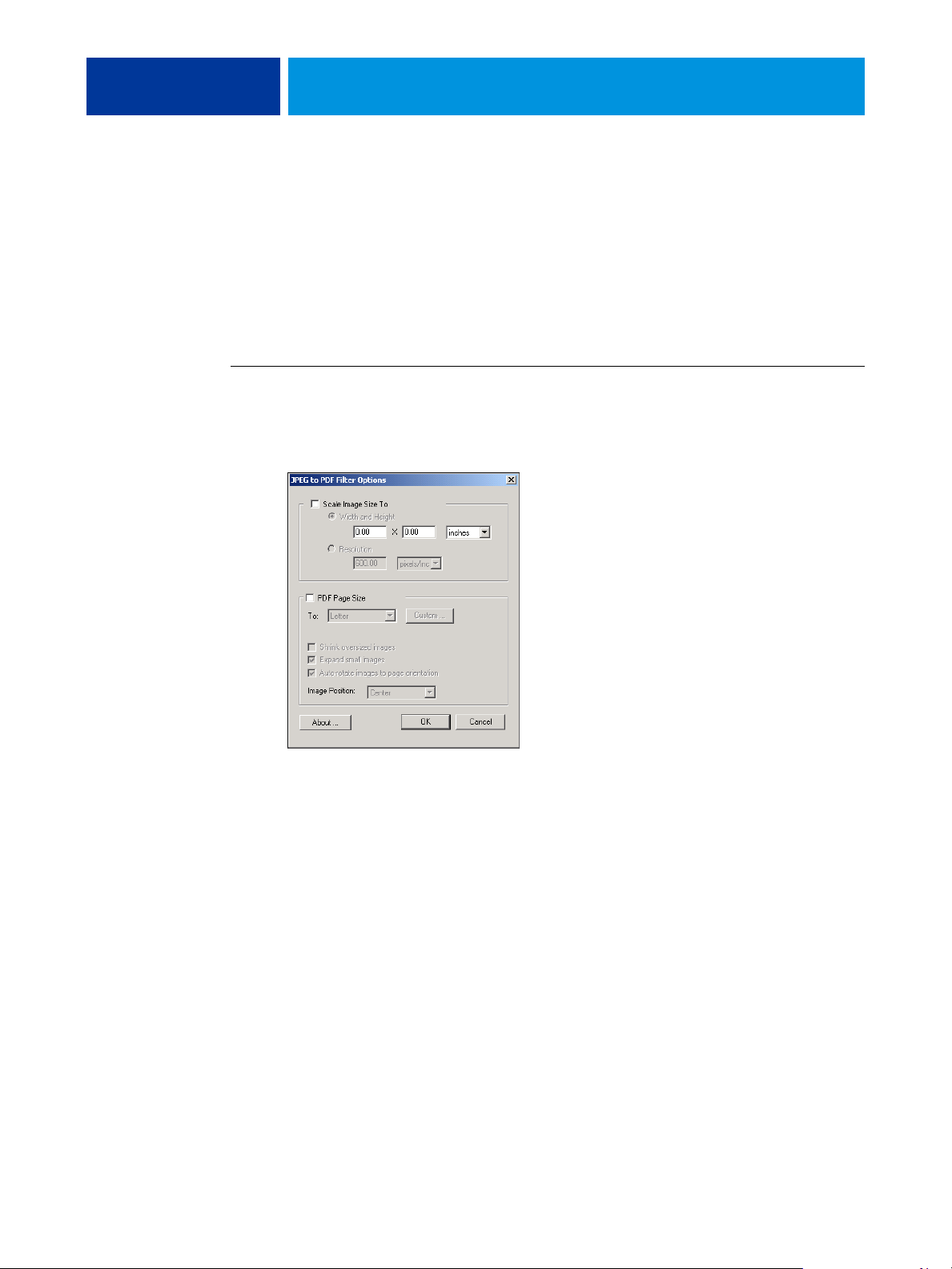
HOT FOLDERS FILTERS 65
Using the JPEG to PDF filter
The JPEG to PDF filter accepts all standard JPEG files. In addition to allowing you to
convert JPEG files automatically without opening them from the application from which they
were created, the JPEG to PDF filter allows you to change the final page size of print jobs and
adjust the resolution.
This filter is Non-exclusive, so you can download basic file formats. For more information
about Non-exclusive filters, see “About file conversion” on page 57.
TO USE THE JPEG TO PDF FILTER
1 Follow steps 1 through 4 in “To select a filter setting” on page 59.
The JPEG to PDF Filter Options dialog box appears.
2 Specify the following options:
Scale Image Size To:
Select this option to scale all JPEG files to the desired image size or
resolution. Select Width and Height, select inches or millimeters from the list, and specify the
values for the image size. Select Resolution, select pixels/inch or pixels/cm from the list, and
specify the value for the resolution.
PDF Page Size: Select this option to print all JPEG files to the page size that you specify. Select
a page size from the list or click Custom and specify a custom page size in the Enter Custom
Paper Size dialog box.
When this option is selected, you can:
• Shrink oversized images to fit proportionately.
• Expand small images to fit proportionately.
• Automatically rotate images to the page orientation.
• Set the position of the image to Top-Left, Top-Right, Center, Bottom-Right, or
Bottom-Left.
3 Click OK.
Page 66

HOT FOLDERS FILTERS 66
Using the PDF/X Preflight filter
PDF/X (PDF Exchange) Preflight is a subset of Adobe PDF designed specifically for prepress
data interchange. It defines how applications that read and create PDF/X files should behave.
Two PDF/X standards are commonly used:
•
PDF/X-1a standard: Addresses blind exchanges to verify that files contain only CMYK
(and/or spot colors), with no RGB or device independent (color-managed) data.
•
PDF/X3: Meets all the requirements of a PDF/X-1a, but contains device independent
(color-managed) data.
The PDF/X Preflight filter allows you to verify that a PDF document is PDF/X-compliant
with either the PDF/X-1a or PDF/X3 standard. If the PDF file is not PDF/X-compliant, the
job fails to process and an error report appears.
TO USE THE PDF/X PREFLIGHT FILTER
1 Follow steps 1 through 4 in “To select a filter setting” on page 59.
The PDF/X Preflight Options dialog box appears.
2 Specify the following options:
Specifications (PDF/X-1a or PDF/X3):
Save Error Report: Select to generate an error report for failed jobs.
Error Report Path: Browse to select an error report location.
3 Click OK.
Select to verify PDF/X-1a or PDF/X3 compliance.
Page 67
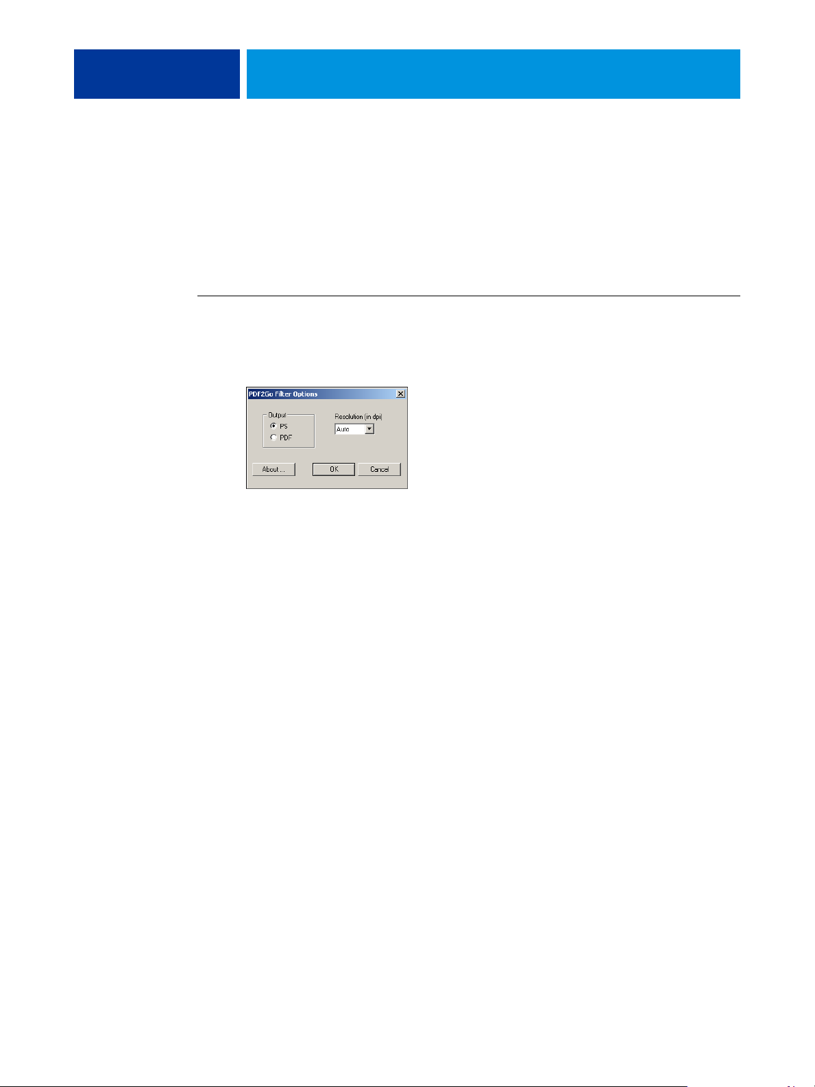
HOT FOLDERS FILTERS 67
Using the PDF2Go filter
PDF2Go is a PDF output developed by Creo-Scitex as an option to their Brisque workflow.
It usually contains PDF layers of rasterized CT and LW job pages, each with a different
resolution, in one PDF file.
The PDF2Go filter processes the PDF2Go file by rendering and re-sampling it to the
resolution of the digital press. You can select PostScript or PDF output.
TO USE THE PDF2GO FILTER
1 Follow steps 1 through 4 in “To select a filter setting” on page 59.
The PDF2Go Filter Options dialog box appears.
2 Specify the following options:
Output (PS or PDF): Select the final output.
Resolution (Auto, 200, 400 or 600): Select the final resolution of the output. Select Auto to
use the device resolution of the digital press.
3 Click OK.
Page 68

HOT FOLDERS FILTERS 68
Using the TIFF to PDF filter
The TIFF to PDF filter accepts TIFF files up to TIFF 6.0. In addition to allowing you to
convert TIFF files automatically without opening them from the application from which they
were created, the TIFF to PDF filter allows you to change the final page size of print jobs and
adjust the resolution.
This filter is Non-exclusive, so you can download basic file formats. For more information
about Non-exclusive filters, see “About file conversion” on page 57.
TO USE THE TIFF TO PDF FILTER
1 Follow steps 1 through 4 in “To select a filter setting” on page 59.
The TIFF to PDF Filter Options dialog box appears.
2 Specify the following options:
Scale Image Size To:
Select this option to scale all TIFF files to the desired image size or
resolution. Select Width and Height, select inches or millimeters from the list, and specify the
values for the image size. Select Resolution, select pixels/inch or pixels/cm from the list, and
specify the value for the resolution.
PDF Page Size: Select this option to print all TIFF files to the page size that you specify. Select
a page size from the list or click Custom and specify a custom page size in the Enter Custom
Paper Size dialog box.
When this option is selected, you can:
• Shrink oversized images to fit proportionately.
• Expand small images to fit proportionately.
• Automatically rotate images to the page orientation.
• Set the position of the image to Top-Left, Top-Right, Center, Bottom-Right, or
Bottom-Left.
3 Click OK.
Page 69

HOT FOLDERS FILTERS 69
Using the TIFF/IT to PostScript filter
TIFF/IT (Tagged Image File Format/Image Technology) is a common TIFF standard.
The TIFF/IT-p1 file format usually consists of three files. All TIFF/IT-p1 files contain an
FP (Final Page) file. The FP file includes page dimension and position required subfiles, such
as CT (Contone) and LW (Line Work) files. CT files contain all photographic imagery.
LW files contain high resolution data, such as line art images, text, or lines from drawings.
TIFF/IT-p1 files may also include MP (Monochrome Picture), HC (High resolution
Contone), BL (Binary Line), or BP (Binary Picture) files.
When you drag and drop your TIFF/IT-p1 files, your output is a pre-separated PostScript
with one separation per page.
Follow these guidelines to convert your TIFF/IT-p1 job:
• Enable the Combine Separations print option. For more information about this option,
see Color Printing.
• Make sure that you have all the necessary files for the TIFF/IT-p1 job. You must place all
of the files in the Hot Folder at the same time. If a file is missing, the job will not process
and you will receive an error.
• If the multiple files for the TIFF/IT-p1 job are stored in a folder, you may place the entire
folder in the Hot Folder.
• If you download the TIFF/IT-p1 job using the Download command, all files may be
inside a folder and the entire folder may be downloaded.
NOTE: The imposition feature is not available if you configure the TIFF/IT to PostScript
filter.
Page 70

HOT FOLDERS FILTERS 70
TO USE THE TIFF/IT TO POSTSCRIPT FILTER
1 Follow steps 1 through 4 in “To select a filter setting” on page 59.
The TIFF/IT Filter Options dialog box appears.
2 Specify the following options:
Resolution (Auto, 200, 400, or 600):
Select the final resolution of the PostScript output from
the list. Select Auto to use the device resolution of the digital press.
Compression (None or RLE Lossless): Select if you want compression for your PostScript
output.
Anti-Aliasing (Nearest Neighbor Faster or Bilinear Better): Select how you want to partially
fill the edge pixel by choosing the Anti-Aliasing method for your PostScript output.
3 Click OK.
Page 71

POSTFLIGHT
POSTFLIGHT 71
The Postflight feature helps you determine why some printed jobs may not deliver expected
color. Acting as a diagnostic and training tool for all users, it provides helpful global and
object-specific information about how a job is actually received and processed by the EX8002.
Use Postflight to troubleshoot color problems with a previously printed job or as a preventive
measure. You can print the original document (or RIPped and previewed) with all objects
(images, graphics, and text) color-coded. A report explains what color spaces are used in the
job and what print options affect those spaces. The report also provides information about the
printing environment, such as calibration date, time, and method. Print a Test Page to verify
the condition of the printing environment.
Postflight is a powerful analysis tool that enumerates in its reports not only those color spaces
that are used by visible objects, but any color space called by a job. This can be very useful in
diagnosing puzzling situations that may require correction. For example: using one specific
combination of a printer driver, an OS, and a desktop publishing application emitting
separations for plates, you might find that: 1) the Postflight color-coded pages show the Cyan,
Magenta, and Yellow separations in the “DeviceGray” color space, while the Black separation
is shown in the “DeviceCMYK” color space and 2) the Postflight report enumerates:
DeviceGray, DeviceCMYK and DeviceRGB. What once required a PostScript expert to
decipher can now be interpreted in minutes using Postflight reports. The Cyan, Magenta, and
Yellow pages are defined in “DeviceGray”, the Black page is using the “K” channel of
DeviceCMYK, and the job is calling for the RGB color space, without applying it on any
user-visible object.
Page 72

POSTFLIGHT 72
About Postflight
When the Postflight print option is set to values other than Off, it provides the following
information to help you identify possible problems: Postflight Test Page, Postflight colorcoded pages, and Postflight reports.
Postflight Test Page
You can print the Postflight Test Page alone or in combination with the color-coded pages.
The Test Page is printed using the exact same media and global settings (such as calibration)
as your job. However, color objects on this page are printed independently of the userspecified source color definitions (such as CMYK simulation and RGB).
If the color on this page is not accurate, the problem lies with the printing environment
(such as the calibration, output profile, or print device).
If the color on this page prints correctly but objects in your job do not print in expected
colors, it is likely that the problem lies with the color setting specific to these objects.
Problems with objects can be: wrong color values for text and graphics, bad quality images,
or out-of-gamut colors.
Postflight color-coded pages
With this option, Postflight prepares a color-coded version of the original document that
displays each object with a color corresponding to the color space that the EX8002 received
for the object.
The colors used to represent the color spaces for objects are as follows:
•Gray objects: Gray
•CMYK objects: Cyan
• RGB objects: Red
• Device-Independent objects: Indigo
• Spot color objects: Yellow
By reviewing the colors for all objects, you can identify the print option settings that affect
the color conversion of the objects and make appropriate modifications.
Page 73

POSTFLIGHT 73
Postflight reports
You can print two types of reports on color-coded pages, either alone or combined with the
color-coded document. These reports are printed on the EX8002 default paper size (Letter for
US, A4 for metric) and use the default calibrated color mode.
Select the Postflight report from the following two types:
•
Detailed Report includes detailed static information with advice on possible procedures
and values. An icon identifies the “detailed” information areas of the report.
•
Concise Report includes only job-specific information. This option is good for advanced
users who do not want the instructions which may seem redundant to them.
Detailed and Concise Reports
The reports provide a document header with information (such as job name, date and time
printed, and user name), a ColorWise global settings page, and object-specific settings pages.
All pages include the job name, postflight date/time, and pagination in the bottom margin.
•
ColorWise global settings page provides information that affects every object in a job, such
as Calibration Set, the date the EX8002 was calibrated, the method used for calibration,
and the output profile that was used.
•
Object-specific settings pages provide a list of the settings that were used to process every
object in each color space, thus suggesting the locations to correct problems. For example,
if you see a problem with an object that is displayed in Cyan in a color-coded page, review
the settings listed in the CMYK Objects page and try changing those settings.
•
Spot colors page lists all spot colors.
For spot colors, the Postflight report lists the colors that are used in a job. It also indicates
whether these colors are defined in the EX8002. When a spot color is defined in the
EX8002, a patch is printed next to the color name. When a color is not defined in the
EX8002, a white patch with an X is printed.
Important notes on Postflight reports
The main purpose of Postflight is to help you detect, diagnose, and prevent color-related
problems. In contrast to generic preflight software, which attempts to predict how a job
would be processed, a postflighted job is fully processed by the EX8002, allowing accurate
reporting on the settings with which the job processed.
This Postflight feature is especially useful in cases where a workflow that was used to submit a
job inadvertently converts colors. This conversion occurs with some printer drivers, printing
options, and conversions to PDF.
Page 74

POSTFLIGHT 74
This report focuses on color processing and does not list every printing option that affects
your job. For more information about the ColorWise print options, see Color Printing.
NOTE: Postflight reports list only those color spaces that were submitted to the EX8002 with
your job. You may occasionally find that a job produces a Postflight report that includes
information about color spaces that you cannot locate in the job’s color-coded pages. This
occurs when an object in the color space is used in the job but is masked by another object,
when an object is very light (for example, 0% of a spot color), or when the specific application
or printer driver asks the EX8002 to process a particular color space but does not use it for
user-visible objects.
NOTE: A Postflight report contains only one page on global settings, and it can include only
one Test Page. Therefore, Postflight cannot describe an entire job accurately unless all pages
are printed with the same options and on the same media. This is the case, for instance, with
Mixed Media jobs, because they can use multiple output profiles, up to one profile per media
in the job. If the page range is set to the pages that use one media only, Postflight produces
reliable results for the specified range.
NOTE: Postflight is a “reporting” feature that is designed for diagnostic purposes. It is not
designed for use with production features such as VDP and Imposition. For high-volume
applications in production environments, use Postflight only on the individual pages that
need testing.
Postflight print option
Access the Postflight feature through the Postflight print option. The following values are
available for the Postflight print option:
• Off (Default)
•Detailed Report
•Concise Report
•Test Page
• Color-Coded Pages
• All Components (Color-Coded document pages, Test Page, and Detailed Report)
NOTE: Select a portion of a job to print the Postflight pages by selecting the appropriate page
range of a job from the printer driver.
Page 75

POSTFLIGHT 75
Postflight workflow
The default settings in the ColorWise print options are such that in most cases you should not
have to change them. However, there may be times when you receive unexpected colors for
your job. Postflight is a procedure performed after you print a document and receive
unexpected or inadequate color. If you have access to Command WorkStation, Postflight also
helps you catch color problems before you actually print. Postflight processes your job and
collects information about the color objects throughout. The information is then displayed in
Color-Coded document pages, a Test Page, and a Detailed or Concise Report.
NOTE: The background defined in the Paper Simulation is not indicated as a CMYK object in
the Postflight reports. For more information about Paper Simulation, see page 13.
NOTE: You cannot use Postflight at the same time that you use the following features:
Progressives, Substitute Colors, or Combine Separations. Constraints are set for these print
options from the printer driver.
The follows scenarios show how Postflight can be helpful to users who demand high color
quality.
To diagnose an unexpected color (see page 77)
Use Postflight to diagnose unexpected color in a job, or determine which print or calibration
settings apply to a job.
To check the calibration status prior to printing a job (see page 79)
Consider the following before printing a job:
• The EX8002 may include many Calibration Sets. Which Calibration Set applies to
my job?
• When was the EX8002 last calibrated?
• Which instrument was used for the last calibration?
Page 76

POSTFLIGHT 76
To check the quality of the output profile (see page 80)
If you are considering using a new paper for which you do not have a custom profile, or if you
suspect that the output profile for your print device may not precisely describe its color
behavior, check your output profile by printing the Postflight Test Page.
To diagnose a color problem of a specific object (see page 81)
When experts have verified that the calibration is correct and that the global settings,
including the output profile, are correct, but the color of a specific object is still not as
intended, you can print a color-coded document and diagnose the problem.
The detailed procedures of these scenarios are described in the following sections.
NOTE: For each of the following procedures, instead of printing the report to the EX8002, you
can also send it to the Hold queue of the EX8002 and preview the information (of a job with
raster data) in ImageViewer. For more information about ImageViewer, see ImageViewer. To
view the color of a job correctly, you must set your monitor and monitor profile correctly. For
more information about the monitor and monitor profiles, see page 12.
NOTE: The procedures for printing a job from a Windows and a Mac OS computer are
similar.
Page 77

POSTFLIGHT 77
Scenario 1: Diagnose an unexpected color
Use the following procedure to print a job with Postflight set to Off.
TO PRINT A JOB
1 Open a job from your application.
2 Choose Print.
3 Select EX8002 as your printer and click Properties.
The Properties dialog box appears with the Fiery Printing tab selected.
4 Click each option icon, and specify the values for each print option.
5 Click the Job Info icon.
6 Choose Off from the Postflight menu.
7 Click OK to close the Properties dialog box.
8 Click Print.
The job is printed to the EX8002.
After you print a job, use the following procedure to diagnose an unexpected color and print
the job with edited color settings.
Page 78

POSTFLIGHT 78
TO DIAGNOSE AN UNEXPECTED COLOR AND PRINT WITH EDITED COLOR SETTINGS
1 Click the Job Info icon.
2 Choose All Components from the Postflight menu.
For information about the components of Postflight, see page 72.
3 Click OK to close the Properties dialog box.
4 Click Print.
Postflight Test Page, color-coded document pages, and Postflight Reports are printed.
5 Review all Postflight pages.
For information about the Postflight pages, see page 72.
6 Make appropriate changes based on all Postflight pages.
For more information about the changes, see the following section.
7 Choose Off from the Postflight menu.
8 Click OK.
9 Click Print.
The job with the edited color settings is printed to the EX8002.
10 Return to Step 1, if needed.
Repeat the steps until you get satisfactory color results.
Making changes
After reviewing the Postflight information, determine what changes are necessary and apply
the changes. Depending on your printing environment, the condition of the print device, and
the color settings, possible changes are as follows:
• Correct problems with the print device (see the documentation that accompanies the
print device).
• Calibrate the EX8002 (see Color Printing).
• Edit the colors of the output profile with Color Editor (see Color Printing).
• Change the default settings in the Color Process Flow tab in Color Setup (see Color
Printing).
• Change the job specific print option settings using Command WorkStation overrides.
Page 79

POSTFLIGHT 79
Scenario 2: Check the calibration status
Use the following procedure to check the calibration status prior to printing a job.
TO CHECK THE CALIBRATION STATUS AND PRINT WITH THE OPTIMUM CALIBRATION CONDITION
1 Click the Job Info icon.
2 If you have not printed the Detailed Report, choose Detailed Report Only from the
Postflight menu.
If you have printed the Detailed Report and are familiar with the content, select
Concise Report Only.
For information about Postflight reports, see page 73.
3 Click OK.
4 Click Print.
The Detailed Report or Concise Report page is printed.
5 Review the information in the ColorWise global settings page.
6 Perform calibration, if needed.
If service has been performed on the print device since the last calibration, or calibration has
not been performed, perform calibration using the Calibration Set specified in the Postflight
report.
For more information about Calibration Set, see Color Printing.
7 Choose Off from the Postflight menu.
8 Click OK.
9 Click Print.
10 The job is printed to the newly calibrated EX8002.
Page 80

POSTFLIGHT 80
Scenario 3: Check the quality of the output profile
Use the following procedure to check the quality of the output profile of the print device.
TO CHECK THE QUALITY OF OUTPUT PROFILE AND PRINT WITH THE OPTIMUM OUTPUT PROFILE
1 Click the Job Info icon.
2 Choose Test Page Only from the Postflight menu.
For information about the Postflight Test Page, see page 72.
3 Click OK.
4 Click Print.
Postflight Test Page is printed to the EX8002.
5 Review the quality of the color on the Postflight Test Page.
NOTE: Make sure that this page was printed with the same media and print option settings as
the job.
6 Review the instructions on the Postflight Test Page.
7 Edit the color of the output profile, or create a profile, if needed.
It may be necessary to customize the output profile or create one to get optimal results on the
media the job is using.
8 Choose Off from the Postflight menu.
9 Click OK.
10 Click Print.
The job is printed to the EX8002 with the edited or newly created output profile.
Page 81

POSTFLIGHT 81
Scenario 4: Diagnose a color problem of a specific object
Use the following procedure to diagnose a color problem.
TO DIAGNOSE A COLOR PROBLEM OF A SPECIFIC OBJECT AND PRINT WITH THE EDITED COLOR SETTINGS
1 Click the Job Info icon.
2 Choose Color-Coded Pages Only from the Postflight menu.
For information about Postflight color-coded pages, see page 72.
3 Click OK.
4 Click Print.
Postflight color-coded pages are printed to the EX8002.
NOTE: Alternatively, you can send the Postflight color-coded pages to the Hold queue of the
EX8002 and preview them using ImageViewer. To preview the pages using ImageViewer,
make sure that your monitor is set up according to the manufacturer’s recommendations and
that the correct monitor profile is specified for your monitor. For information about monitor
profiles, see page 12.
5 Review the Postflight color-coded pages.
6 Make changes to the color settings, if needed.
For information about the ColorWise print options for various color spaces, see Color
Printing.
NOTE: Use the Color-Coded Pages Only setting to send a job to another print device that has
a specific color-space requirement. For example, a document targeted to a CMYK-only press
must have only Cyan-colored objects.
7 Choose Off from the Postflight menu.
8 Click OK.
9 Click Print.
The job is printed to the EX8002 with the edited color settings.
Page 82

MULTIPLE PLATE SEPARATIONS 82
MULTIPLE PLATE SEPARATIONS
The Multiple Plate Separations feature allows you to combine the multiple pre-separated
color plates of a PostScript job into a composite color print. It supports: Cyan, Magenta,
Yellow, Black, and one or more spot colors.
The results of combining the multiple plates are predictable and accurate, regardless of the
original application used. This feature also fully supports DCS 2.0 file formats when included
in a PostScript print job from a page layout application.
Multiple plate separations workflow
Use the following procedure to print a composite color print from the printer driver.
NOTE: The procedures for printing a composite color print from a Windows and a Mac OS
computer are similar.
TO PRINT A COMPOSITE COLOR PRINT
1 Open a color-separated document in a supported application.
2 Choose Print.
3 Select EX8002 as your printer and click Properties.
The Properties dialog box appears with the Fiery Printing tab selected.
4 Click the Color icon.
5 Select Combine Separations.
6 Click Print.
A composite color print is printed to the EX8002.
Page 83

MULTIPLE PLATE SEPARATIONS 83
Combine Separations print option
Access the Multiple Plates Separations feature through the Combine Separations print option
from the printer driver.
The following values are available for the Combine Separations print option:
• Off (Default)
•On
Supported applications
The following applications have been tested with Mac OS and Windows for compatibility
with the Multiple Plates Separations feature:
• Adobe Illustrator
• Adobe InDesign
• Adobe PageMaker
• Adobe FreeHand
• QuarkXPress
Page 84

PAPER SIMULATION
The Paper Simulation feature gives you the benefit of the absolute colorimetric rendering that
renders the white point of the source color space as a visible color in the output profile color
space.
Paper Simulation workflow
Use the following procedure to print a job with the fixed Paper Simulation feature On.
NOTE: The procedures for setting the Paper Simulation print option from a Windows and a
Mac OS computer are similar.
PAPER SIMULATION 84
TO PRINT WITH THE FIXED PAPER SIMULATION FEATURE ON
1 Choose Print from an application.
2 Select EX8002 as your printer and click Properties.
The Properties dialog box appears with the Fiery Printing tab selected.
3 Click the Color icon, and then click Expert Settings.
The Expert Color Settings dialog box appears.
4 Choose On from the Paper Simulation list and click OK.
5 Click Print.
The job is printed with the fixed Paper Simulation feature.
Page 85

PAPER SIMULATION 85
Paper Simulation print option
Turn the Paper Simulation feature on or off through the print option from the printer driver.
•
On: Performs Absolute Colorimetric rendering.
•
Off (Default): Performs Relative Colorimetric rendering.
Page 86
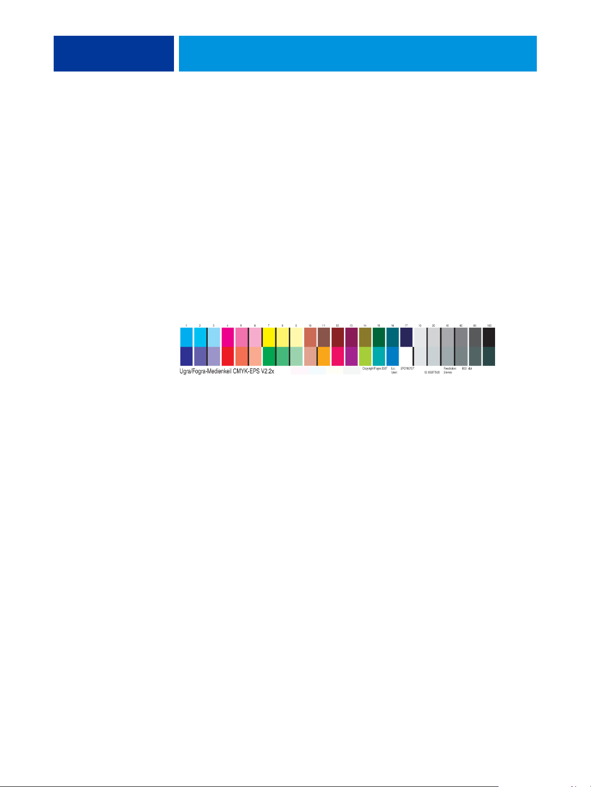
UGRA/FOGRA MEDIA WEDGE 86
UGRA/FOGRA MEDIA WEDGE
Ugra (the Graphic Technology Research Association of Switzerland) and FOGRA (the
Graphic Technology Research Association of Germany) are organizations that support
standardization and quality control. Together, they developed the Ugra/FOGRA Media
Wedge CMYK v2.0, a control device used to evaluate hard copy proofs. One version of the
the Ugra/FOGRA Media Wedge, which is supported by the EX8002 with Fiery Graphic Arts
Package, Premium Edition enabled, is customized for the ES-1000 spectrophotometer.
The Ugra/FOGRA Media Wedge, as printed on the EX8002, includes the standard color
patches as well as the digital press resolution, EX8002 model name, and other static
information required by Ugra/FOGRA.
Adding the Ugra/FOGRA Media Wedge to any job allows you to check the color accuracy
and consistency of the digital press by measuring the colors in the Ugra/FOGRA Media
Wedge with the ES-1000 and supporting software, and comparing the measurements to
reference values.
Printing the Ugra/FOGRA Media Wedge
There are two ways to include the Ugra/FOGRA Media Wedge in a job:
• By incorporating the Ugra FOGRA-MediaWedge V2.2x.EPS file in the source document.
This file is available on the User Software DVD, in the Color Bars folder inside the
Windows Color Files folder or Mac Color Files folder.
• By specifying the Ugra FOGRA-MediaWedge V2.2x.EPS file as a custom control bar used
by the Control Bar print option. You can then include the Ugra/FOGRA Media Wedge in
any job by enabling the Control Bar print option.
For more information about the Control Bar print option, see “Control Bar” on page 29.
NOTE: This version of the Ugra/FOGRA Media Wedge is different from the Ugra/FOGRA
Media Wedge used in the Integrated Altona Visual Test. For more information about the
Integrated Altona Visual Test, see Integrated Altona Visual Test.
Page 87

UGRA/FOGRA MEDIA WEDGE 87
The Ugra FOGRA-MediaWedge V2.2x.EPS file is not an ordinary EPS file. Printing this file
is supported only on a EX8002 with the Fiery Graphic Arts Package, Premium Edition
enabled. The file will not print if modified and saved as another version. You cannot currently
use Compose, Impose, or QDM to embed the Ugra/FOGRA Media Wedge image in a PDF
file.
Reading the Ugra/FOGRA Media Wedge
This version of the Ugra/FOGRA Media Wedge is optimized for the ES-1000. Other stripreading or spot-reading spectrophotometers may be used, if supported by their applications.
EFI Color Verifier (part of EFI Color Profiler Suite) is the quality control application officially
supported to measure the Ugra/FOGRA Media Wedge as printed by the EX8002.
Reference measurements are not supplied with the Ugra/FOGRA Media Wedge. Software
such as EFI Color Profiler Suite lets you create your own reference measurements, extract
them from reference ICC profiles, or load them from standards.
Using the Ugra/FOGRA Media Wedge for quality control
You can use the Ugra/FOGRA Media Wedge to compare digital proofs with print standards,
print runs with print standards, and digital proofs with print runs. It was originally designed
to check the accuracy and consistency of CMYK values when compared to the international
ISO 12642 standard, but this is not its exclusive usage: when the Ugra/FOGRA Media Wedge
is printed in a job, you can measure the color accuracy and consistency of the output device
for any printing condition, whether CMYK simulation or device CMYK color.
Page 88

INTEGRATED ALTONA VISUAL TEST 88
INTEGRATED ALTONA VISUAL TEST
The Altona Test Suite is a project of the European Color Initiative (ECI). The test suite is
suited for evaluating RIPs as well as other components in composite PDF workflows for print
proofing or print production. Even if you are not yet using PDF/X3, you can use the Altona
Test Suite to identify the weaknesses and limitations of a PDF workflow.
The Integrated Altona Visual Test feature of the Fiery Graphic Arts Package, Premium
Edition allows you to verify the level of PDF/X support provided by the software and
hardware used in a composite PDF workflow. You perform this test by printing the free
version of the Altona Visual Test document on the EX8002 using the PDF workflow you
want to verify. The EX8002 adds information to the printed output that can be used to
determine:
• If the workflow used to send PDF documents to the EX8002 is PDF/X compatible.
• If a PDF/X workflow is compatible with the limited interpretation of PDF/X by Altona.
• If the color quality of a PDF/X workflow meets a standard.
The Integrated Altona Visual Test simplifies the setup and verification of PDF workflows. You
can verify Altona PDF/X compliance without having to purchase the Altona Test Suite
Application Kit.
Altona Visual Test file
You can obtain the free version of the Altona Visual Test file that you need for the Integrated
Altona Visual Test (a file named
http://www.eci.org/doku.php?id=en:downloads
This PDF file must be imported to the EX8002 using Command WorkStation or Hot
Folders, not printed through the printer driver. The printer driver converts a PDF file to
PostScript, and therefore some PDF/X embedded information is lost. A PDF/X workflow
cannot include printing through a printer driver.
Altona_Visual_1v2a_x3.pdf ) at:
Page 89

INTEGRATED ALTONA VISUAL TEST 89
For PDF/X compliance as tested by Altona, set the following settings for the Altona Visual
Test job in Command WorkStation Job Properties:
Print option Setting Location in Job Properties
Use PDF/X Output Intent Enabled Expert Color Settings (in Color)
Composite Overprint Enabled Color
RGB Source Profile None Expert Color Settings (in Color)
RGB Separation Simulation Expert Color Settings (in Color)
Scale 100% (no scaling) Layout
Scaling the Altona Visual Test file and any file designed with resolution-dependent objects
often leads to artifacts such as moirés.
For more information about these print options, except for Scale, see Color Printing. For more
information about Scale, see Printing.
1 Test result area
If you use all of these settings, the Altona Visual Test File output will indicate PDF/X
compliance as tested by Altona.
Interpreting test results
The Altona Visual Test file produces the printed page shown below. The EX8002 inserts the
test results in the lower left area.
1
Page 90

INTEGRATED ALTONA VISUAL TEST 90
The table below indicates how to read the test results:
Test result Indicates
Blank File printed to a EX8002 without the Integrated Altona Visual Test
feature or workflow is not PDF/X compatible.
A message indicating that the
Workflow is not compatible with PDF/X as tested by Altona.
test file was not processed with
optimal settings for Altona
Ugra/FOGRA Media Wedge
Workflow is compatible with PDF/X as tested by Altona.
(a standard set of color bars)
If the Ugra/FOGRA Media Wedge, shown in the figure below, is printed in the test result
area, the workflow is PDF/X compatible for Altona testing. It is therefore correct to visually
and colorimetrically inspect the page. If you have a spectrophotometer, such as the ES-1000,
and quality control software, such as EFI Color Verifier, you can proceed with measurements
to evaluate the degree of color matching. The version of the Ugra/FOGRA Media Wedge
inserted by the EX8002 is scaled and positioned for easy reading by a strip-reading
instrument.
1 2 3 4 5 6 7 8 910111213141516171020406080100
Liz.: 2FO180107Copyright Fogra 2007 Resolution: 600 dpi
Ugra/Fogra-Medienkeil CMYK-EPS V2.2x ID: 85377533
User: Version EFI 2007 Device: EFI Fiery Demo
NOTE: Be sure to use the free version of the Altona Visual Test file, not the purchased one. The
purchased version always includes a version of the Ugra/FOGRA Media Wedge in the bottom
left area, whether the workflow is valid or not. In addition, the version of the Ugra/FOGRA
Media Wedge printed by the purchased version cannot be read conveniently by a strip-reading
instrument.
The Integrated Altona Visual Test confirms if your workflow maintains PDF integrity and if
it produces valid output that can be used for further analysis and interpretation. To formally
determine the level of PDF/X compliance, refer to Adobe published documentation. For
information on how to interpret printed Altona pages, refer to the documentation available
from the European Color Initiative (ECI).
For information on the Ugra/FOGRA Media Wedge and how to use it for quality control in
user designed workflows, see Ugra/FOGRA Media Wedge.
Page 91

INTEGRATED ALTONA VISUAL TEST 91
Using a PDF/X workflow not compatible with Altona
If text appears in the test result area instead of the Ugra/FOGRA Media Wedge, you cannot
use the page for further Altona testing because the workflow is not PDF/X compatible as
tested by Altona. However, the EX8002 is not limited to the Altona interpretation of PDF/X.
In particular, if you are using the EX8002 for production printing rather than proofing, you
might choose job settings that are not PDF/X compatible as tested by Altona. For example,
you might choose to:
• Set RGB Separation to Output instead of Simulation in production PDF/X workflows, to
exploit the maximum gamut of the digital press.
• Scale down the document to increase margins or scale it up to reduce margins.
• Use EX8002-specific options, such as Image Smoothing, that would alter the images in
the Altona Visual Test file but would enhance your production output.
To get the best possible output from the Altona Test Suite, refer to the information about the
Altona Visual Test File at
http://www.efi.com/support/production/fiery/production/how-to/sys8/
Altona helps verify PDF/X compliance, with some bias towards ISO color standards. We
recommend that you do not limit yourself to ISO color. PDF/X lets you define your own
color spaces and take advantage of the wider color gamut often possible with digital printers.
For more information about PDF/X and how to create compliant documents, refer to
documents and information available from Adobe.
Page 92

Page 93

INDEX
INDEX 93
A
Altona 86
Auto Trapping
about 36
Apply Auto Trapping option 39
Color Setup 27
configurable 36
default 37
defining 41
factory defaults 40
pane 38
printing 41
tab 38, 41
trap color reduction 39
trap object types 40
trap shape 40
trap width 39
workflow 37
B
Brightness, Paper Simulation 15
C
color accuracy 86
color consistency 86
Color Setup
Auto Trapping 27, 41
Color Process Flow 27
Control Bar 27
Progressives 27
starting 28
Combine Separation
print option 83
Control Bar
about 29
Color Setup 27
Control Bar Definition dialog box 32
Control Bar EPS File 33
creating 32
default control bar 30
defining 32
definitions 32
deleting 35
Distance from the edge 35
duplicating 35
editing 35
factory defaults 36
Job Information 34
pane 31
Print Control Bar option 31
print option 29
printing 36
Reporting print
option 30, 36, 77, 78, 79, 80, 81
System Page Size 33
tab 31
Text Location 34
Ugra/FOGRA Media Wedge 86
workflow 29
CT/LW to PS Filter
about 61
configuring 61
D
DCS 2.0 to PS Filter
about 62
configuring 62
E
EFI Color Profiler Suite 87
EFI Color Verifier 87, 90
EPS to PS Filter
about 63
configuring 63
ES-1000 spectrophotometer 86, 87, 90
Exclusive filters 57
Expert Color Settings 84
ExportPS Filter
about 64
configuring 64
Page 94

INDEX 94
F
file conversion 57
File Filters
about 58
configuring 61
selecting settings 59
specifying 59
FOGRA 86
G
graphic arts features 9
H
Halftone Screen
angle 48
Application Defined 46
calibrating 51
Dot Shape 49
LPI (screen frequency) 48
Mac Color Files folder 51
Newsprint 46
printing 47
User Screen 46
Windows Color Files folder 51
workflow 46
Halftone Simulation
print option 46
tab 48
Hot Folders
about 57
File Filters 57
Hue, Paper Simulation 14
I
ImageViewer, accessing 53
Integrated Altona Visual Test 86, 88
J
JPEG to PDF Filter
about 65
configuring 65
M
monitor compensation, Paper Simulation 18
monitor profile, specifying 12
monitor, setting up 12
Multiple plate separations
workflow 82
N
Non-exclusive filters 57
O
output profile
Control Bar 34
Paper Simulation 15, 16, 17, 21, 84
Postflight 76, 78, 80
Spot-On 23, 25
P
Paper Simulation
Brightness 15
fixed values 13, 84
Full (Output GCR) 17, 21
Hue 14
monitor compensation 18
output profile 17
preview 15
print option 14, 85
printing 19, 84
Save 19
simulation profile 16, 21
white point editing 14
workflow 13, 84
Paper Simulation White Point
dialog box 14
editing 15
Paper Simulation, Saturation 15
PDF/X compatibility 88
PDF/X Preflight Filter
about 66
configuring 66
PDF2GO Filter
about 67
configuring 67
Page 95

INDEX 95
Postf light
about 72
accurate reporting 73
calibration status 75, 79
color problems 76, 81
color-coded pages 72, 81
ColorWise global settings page 73
ColorWise print options 74
Concise Report 73, 79
Detailed Report 73, 79
diagnosing 78
global settings page 79
Hold queue 81
ImageViewer 81
information 78
making changes 78
monitor profile 81
Object-specific settings pages 73
Paper Simulation 75
print option 74
quality of output profile 76, 80
reports 73
Spot colors 73
Test Page 72, 80
unexpected colors 75, 77
vs. Combine Separations 75
vs. Progressives 75
vs. Substitute Colors 75
workflow 75
Preview, Paper Simulation 15
Progressives
color channels 45, 49
Color Setup 27
default 43
factory defaults 45
pane 44, 45
print option 43
printing 46
sheets and colors 44
tab 44
workflow 42
S
Saturation
Paper Simulation 15
spectrophotometer 90
Spot-On, output profile 23
T
terminology 7
TIFF to PDF Filter
about 68
configuring 68
TIFF/IT to PS Filter
about 69
configuring 69
Two-Color Print Mapping
defining 23
printing 25
U
Ugra/FOGRA Media Wedge 86, 90
Use PDF/X Output Intent 89
Page 96

 Loading...