

Page 1
Xerox 495 Continuous Feed Duplex Printer
Operator Guide
January 2007
708P88702
Page 2

Prepared and translated by:
Xerox,
GKLS European Operations,
WELWYN GARDEN CITY,
AL7 1BU
United Kingdom
©2007 by Xerox Corporation. All rights reserved.
Xerox® and all the products mentioned in this publication are trademarks of Xerox Corporation and Xerox Limited.
Products and trademarks of other companies are also acknowledged.
Copyright protection claimed includes all forms and matters of copyrightable material and information now allowed
by statutory or judicial law or hereinafter granted, including without limitation, material generated from the software
programs which are displayed on the screen such as icons, screen display looks, etc.
Changes are periodically made to the document. Revisions, changes, any technical inaccuracies, and
typographical errors will be corrected in any subsequent editions.
Page 3

Table of Contents
Table of Contents
1. About this manual 1-1
End User License Agreement 1-1
Audience 1-2
Document organization 1-3
Document conventions 1-4
Notes, cautions, and warnings 1-4
2. Product overview 2-1
Front and back marking units 2-2
Default Definition 2-2
Getting to know the printer engine 2-3
Front covers and doors 2-3
Components inside the printer doors 2-4
Components inside the internal door 2-5
Components inside the Fuser Door 2-6
Components inside the stacker door 2-7
Rear covers and doors 2-8
Paper loading components 2-9
Understanding the touch screen 2-10
Screen symbols 2-10
Functional areas 2-12
Title bar 2-13
User area and navigation buttons 2-13
Tab view 2-14
Run view 2-16
Consumables view 2-18
Print line 2-20
Status indicator 2-20
Background colour 2-21
Device name 2-22
Device icon 2-22
Bubble menu 2-23
Status bar 2-23
Action bar buttons 2-25
Printer diagram 2-26
Operator panels 2-28
Sub-operator panel 2-28
Autoload panel 2-30
Stacker panel 2-32
Paper forward and reverse switch panel 2-33
Pre- and post-processing equipment 2-34
Xerox 495 Continuous Feed Duplex Printer Operator Guide Page -i
Page 4

Table of Contents
The Print Line Bus (PLB) 2-35
Identifying the PLB boxes 2-35
Cabling the PLB 2-35
Characteristics 2-36
Segmentation 2-36
Licensing 2-37
Renewing the license 2-38
3. Getting started 3-1
Switching the printer on and off 3-2
Local power on and off 3-2
Remote powering on and off 3-3
Emergency stop 3-4
Using help 3-5
Making general configurations 3-6
Setting the time on the screen 3-7
Setting print modes 3-8
Changing user roles 3-10
Setting locked components 3-11
Changing the password 3-12
Changing the user language 3-12
4. Running production jobs 4-1
Quick start 4-2
Running jobs 4-3
Changing the notebook settings 4-6
Notebook paper settings 4-7
Notebook offsets 4-7
Notebook density settings 4-8
Notebook 2-up settings 4-8
Setting the Check Output value 4-9
Bubble menus 4-11
Bubble menu possibilities 4-12
Cancelling jobs 4-14
Cancelling a print job 4-14
Cancelling a print position check 4-14
5. Paper path 5-1
Ejecting paper from the printer 5-2
Paper Loading 5-3
Loading on the hopper 5-3
Paper autoloading 5-4
Setting the perforation position 5-9
Cutting paper 5-11
Removing Paper 5-12
Checking printing 5-14
Checking printed paper 5-14
Checking at the printing check position 5-14
Check by the printing position check function 5-15
Loading paper to a post-processing device 5-16
6. Adjusting print quality 6-1
7. Defining production jobs 7-1
Quick start 7-2
Page -ii Xerox 495 Continuous Feed Duplex Printer Operator Guide
Page 5

Table of Contents
Checking the existence of a job 7-3
Defining a job 7-4
Defining paper characteristics 7-7
Defining applications 7-12
Defining a paper path 7-21
Defining the attachment 7-28
Importing flash overlays 7-34
Valid print area (VPA) 7-37
Creating or amending a job 7-4
Copying a job definition 7-5
Exporting a job definition to the Production screen 7-5
Importing a job definition from the Production screen 7-6
Deleting a job definition 7-6
Creating or amending a paper definition 7-7
Copying a paper definition 7-10
Exporting a paper definition to the Production screen 7-10
Importing a paper definition from the Production screen 7-10
Deleting a paper definition 7-11
Creating or amending an application 7-12
Copying an application definition 7-19
Exporting an application definition to the Production screen 7-19
Importing an application definition from the Production screen 7-20
Deleting an application definition 7-20
Creating or amending a print line 7-21
Exporting a line definition to the Production screen 7-23
Deleting a line definition 7-23
Reviewing installed devices 7-24
Defining processing marks 7-24
Deleting a marks definition 7-27
Creating or amending an IBM Channel attachment configuration 7-28
Creating or amending a TCP/IP attachment configuration 7-30
Copying an attachment definition 7-33
Exporting an attachment definition to the Production screen 7-33
Deleting an attachment definition 7-33
8. Performing routine maintenance 8-1
Operator tasks 8-2
Ordering Supplies 8-3
Checking consumable use 8-4
Replacing the toner 8-6
Replacing Toner [Ka] 8-6
Replacing Toner [Kb] 8-9
Replacing the developer 8-12
Replacing the roller unit 8-13
Replacing Roller unit A[R1a] 8-13
Replacing Roller unit B[R1b] 8-15
Replacing the cleaner brush and blade 8-18
Replacing kit A[R3a] 8-18
Replacing kit B[R3b] 8-21
Replacing the toner collector 8-24
Replacing the smoke filter 8-26
Cleaning the machine 8-27
The fuser glass (front and back) 8-27
The Toner supply and collector areas 8-28
Cleaning the touch screen 8-29
Calibrating the touch screen 8-30
Xerox 495 Continuous Feed Duplex Printer Operator Guide Page -iii
Page 6

Table of Contents
9. Problem solving 9-1
Clearing errors 9-2
Clearing paper jams 9-3
Locating the paper jam 9-3
Removing non-fused paper 9-6
Clearing a paper jam at autoload 9-9
Clearing a paper jam outside the drum unit 9-10
Clearing a post-processor jam 9-11
Paper jam inside printer when connected to a post-processing device 9-11
Paper jam between printer and post-processing device 9-11
Checking software and hardware revisions 9-12
Using the tools screen 9-13
Displaying the error log 9-13
Printing test overlays 9-16
Status codes 9-17
Error codes 9-18
Printer engine error codes 9-18
System error codes 9-45
A. Safety notes A-1
Warning markings A-1
Electrical supply A-2
Operator accessible areas A-2
Maintenance A-2
Cleaning your product A-2
WARNING - Electrical safety information A-3
Operational safety information A-4
Maintenance information A-5
Ozone safety information A-5
For consumables A-5
Product safety certification A-5
Regulatory Information A-6
CE Mark A-6
Environmental Compliance A-7
Product Recycling and Disposal A-7
European Union A-7
Other Countries A-7
B. Specifications B-1
Basic specifications B-2
Functional specifications B-3
Paper Specifications B-4
C. Principles of Operation C-1
Operation Outline C-2
Information transfer cycle C-2
Recording cycle C-3
Transfer cycle C-3
Fusing cycle C-3
Configuration C-4
Outline of printing process C-5
Paper transport section C-6
Auxiliary units C-6
Controller shelf C-6
Main and sub operator panels C-6
Page -iv Xerox 495 Continuous Feed Duplex Printer Operator Guide
Page 7

Table of Contents
INDEX
Xerox 495 Continuous Feed Duplex Printer Operator Guide Page -v
Page 8

Table of Contents
Page -vi Xerox 495 Continuous Feed Duplex Printer Operator Guide
Page 9

1. About this manual
Thank you for purchasing the Xerox 495 Continuous Feed Duplex
Printer. The printer is designed for ease of use, but to use your machine
to its fullest potential, take some time to read this Operator Guide.
End User License Agreement
In order to operate the Xerox 495 Continuous Feed Duplex Printer, it is
mandatory for an end user representative to accept an XPe (XP
embedded) End User License Agreement (EULA). This is the first action
for an end user representative after installation or a software upgrade on
the machine.
IMPORTANT NOTE:
Only an end user representative can accept the EULA. Service
personnel must not accept the EULA for the end user since that will
invalidate their agreement with Microsoft.
Xerox 495 Continuous Feed Duplex Printer Operator Guide Page 1-1
Page 10

AUDIENCE ABOUT THIS MANUAL
Audience
This Operator Guide is intended to be used by Operators and Key
Operators of the printer in order to run and define production jobs. Some
functions only available to Maintenance and Support level users are also
included. Where procedures are only relevant to specific user levels,
these are clearly identified.
It is assumed that all users understand the peripheral equipment that
may be used in the print line. It is also assumed that suitable operation
manuals will be available for this peripheral equipment.
Page 1-2 Xerox 495 Continuous Feed Duplex Printer Operator Guide
Page 11

ABOUT THIS MANUAL DOCUMENT ORGANIZATION
Document organization
The Operator Guide contains the following sections:
• Chapter 2 - Product Overview which describes the main
components.
• Chapter 3 - Getting Started shows you how to switch the printer off
and on, the use of the Help and how to change from one user role to
another.
• Chapter 4 - shows the procedures for Running Production Jobs.
• Chapter 5 - deals with the procedures for loading paper and making
Paper Path adjustments.
• Chapter 6 - describes Adjusting Print Quality.
• Chapter 7 - contains the procedures for Defining the Characteristics
of Production Jobs.
• Chapter 8 - shows you the procedures for Performing Routine
Maintenance.
• Chapter 9 - deals with Problem Solving.
• Appendix A - contains information on the Approvals and
Certification applied to the printer.
• Appendix B - contains the product and paper specifications for the
printer.
• Appendix C - a description of how the printer functions.
Xerox 495 Continuous Feed Duplex Printer Operator Guide Page 1-3
Page 12

DOCUMENT CONVENTIONS ABOUT THIS MANUAL
Document conventions
A document convention is simply a way of presenting information. This
section explains the conventions used in this Guide.
Notes, cautions, and warnings
This manual uses notes, cautions, and warnings to emphasize
information the reader needs.
Notes contain information that supplements the text.
Cautions provide information where non conformance could cause
damage to the machine.
Warnings are shown where non conformance could cause injury to the
operators.
Notes and cautions are emphasized using italics. Warnings are
emphasized using a bold typeface.
The following is an example of a note:
Note: Notes are provided as additional information.
The following are examples of a caution and a warning:
CAUTION
Do not touch the drum surface. Touching the drum could affect the print
quality.
WARNING
This warning alerts you to areas of the product where there is the
possibility of personal injury.
WARNING
This warning alerts you to areas of the product where there are
heated surfaces, which should not be touched.
Page 1-4 Xerox 495 Continuous Feed Duplex Printer Operator Guide
Page 13
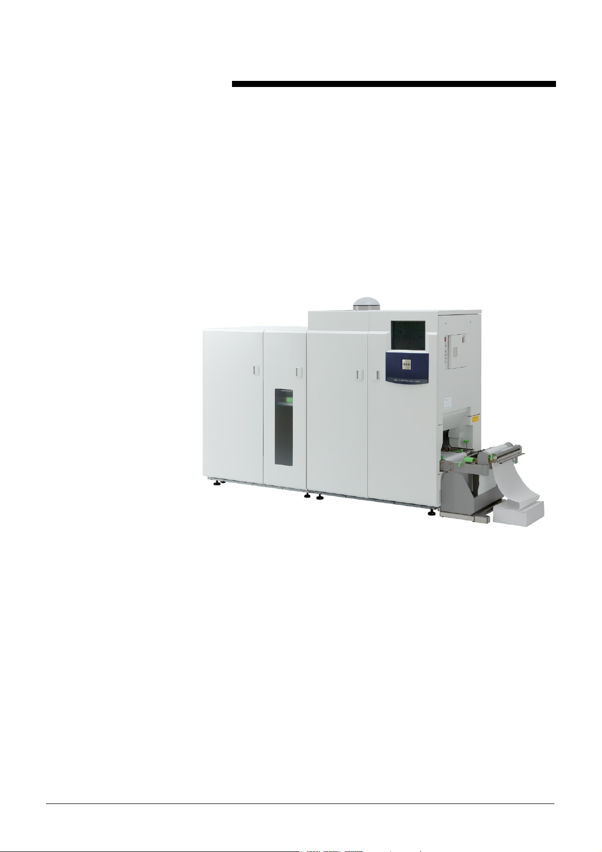
2. Product overview
The Xerox 495 Continuous Feed Duplex Printer is a non-impact
continuous-feed printer combined from the LED recording and dry
electrophotographic recording technologies for double-sided printing.
The machine is controlled from a liquid crystal colour touch screen where
you can view your operation and application settings.
Printer settings can be pre-programmed for specific production job types
and when such a job type is selected, the printer is set up automatically
for the paper type and application. The print line to be used is also predefined and can be selected according to equipment availability and the
job requirements.
Communication with the different devices that form the print line is
achieved using the Print Line Bus (PLB).
On-line connection to the host computer uses a number of industry
standard emulations across the IBM Channel and the TCP/IP protocol.
Paper can be supplied as fanfold fed from the paper feeder or from a roll
feed peripheral device. Printed output can be delivered to a number of
finishing devices. Configuration of the print line is made through the
touch screen.
Access control to the various functions is made by defining a user role
Xerox 495 Continuous Feed Duplex Printer Operator Guide Page 2-1
Page 14

Front and back marking units
Default Definition
PRODUCT OVERVIEW
(Operator, Key Operator, Maintenance and Support) where all users
other than the Operator are required to enter a password to access the
functions.
In order to carry out duplex printing, the printer has two marking units A
(Front) and B (Back). Using the default settings, the front side data will
print on the A marking unit and the back side data will print on the B
marking unit.
You can, however, decide to print the back side data on the A marking
unit and the front side data on the B marking unit by checking the
Reverse Duplex Printing box.
This can be set for a particular line definition (see "Defining a paper path"
on page 7-21) or can be changed on the Production screen (see
"Running jobs" on page 4-3).
Default definitions and values can only be modified by Support users.
Page 2-2 Xerox 495 Continuous Feed Duplex Printer Operator Guide
Page 15
PRODUCT OVERVIEW GETTING TO KNOW THE PRINTER ENGINE
Getting to know the printer engine
Inside the printer you will find the printer engine and the controller. The
Printer Engine contains the image processing, paper handling and
fusing components. The Controller has two PCs which are used to
control printer functions, communications and configurations.
The following illustrations show the major areas of the printer, the
location of the covers and doors and the different control panels and
interfaces.
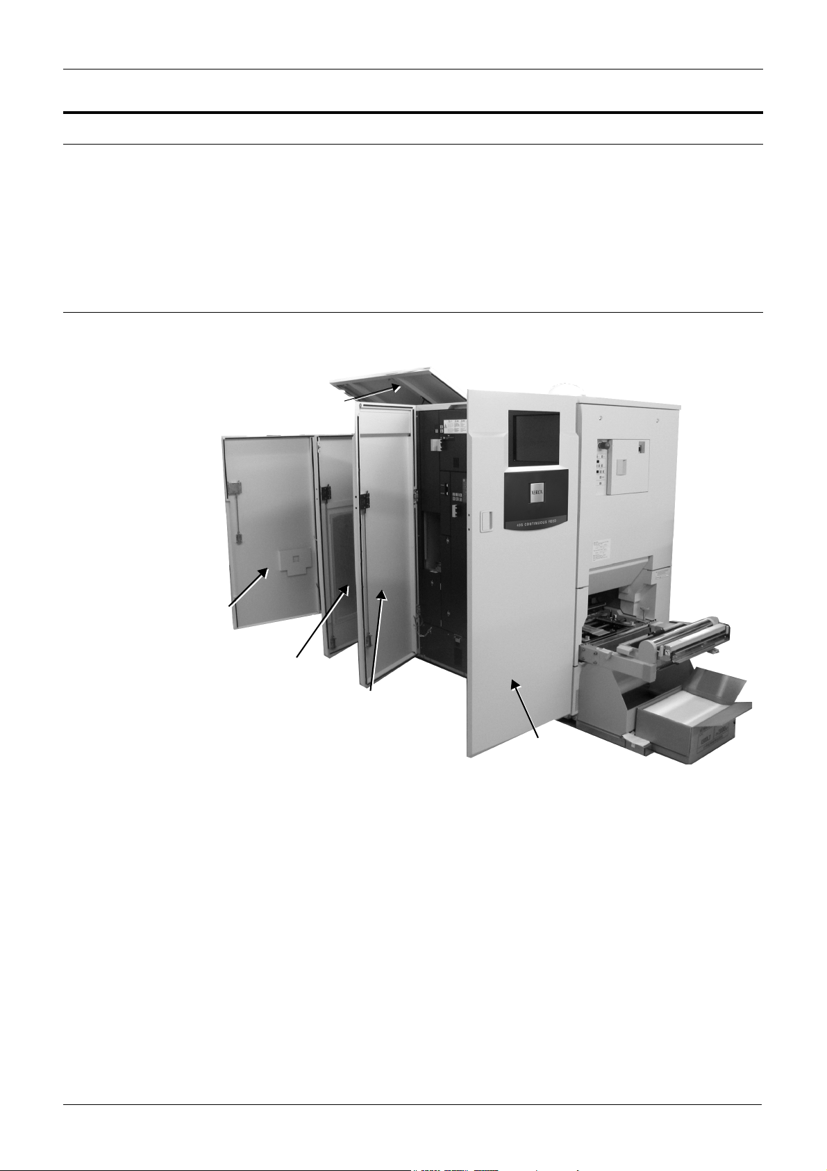
Front covers and doors
The front covers and doors provide access to the printer and stacker
components. The Top Cover provides access to the output paper path.
Top Cover
Left Stacker Door
Right Stacker Door
Left Printer Door
Right Printer Door
The location is referenced as looking from the front.
•The Right and Left Printer Doors provide access to the main
printing units.
•The Right Stacker Door provides access to the paper stacker
output.
•The Left Stacker Door provides access to the printer controller PC.
Xerox 495 Continuous Feed Duplex Printer Operator Guide Page 2-3
Page 16

GETTING TO KNOW THE PRINTER ENGINE PRODUCT OVERVIEW
Components inside the printer doors
Opening the printer left and right doors provides access to the main
printing units.
Fuser Door
Fuser Left Door
Kit B[R3b] Display LED
Toner Supply Unit [Kb]
Internal Door
Toner Display LED [Kb]
Developer Display LED
[R2b]
Touch Screen
Kit A[R3a] Display LED
Toner Supply Unit [Ka]
Toner Display LED [Ka]
Developer Display
LED [R2a]
The Touch screen is used to run and configure production jobs. This
also provides access to a number of maintenance functions. See
“Understanding the touch screen” on page 2-10.
The Internal Door accesses the maintenance task components. See
“Components inside the internal door” on page 2-5.
The Fuser Door provides access to the fusing components. See
“Components inside the Fuser Door” on page 2-6.
The remaining components provide maintenance indicators. See
“Performing routine maintenance” on page 8-1.
Page 2-4 Xerox 495 Continuous Feed Duplex Printer Operator Guide
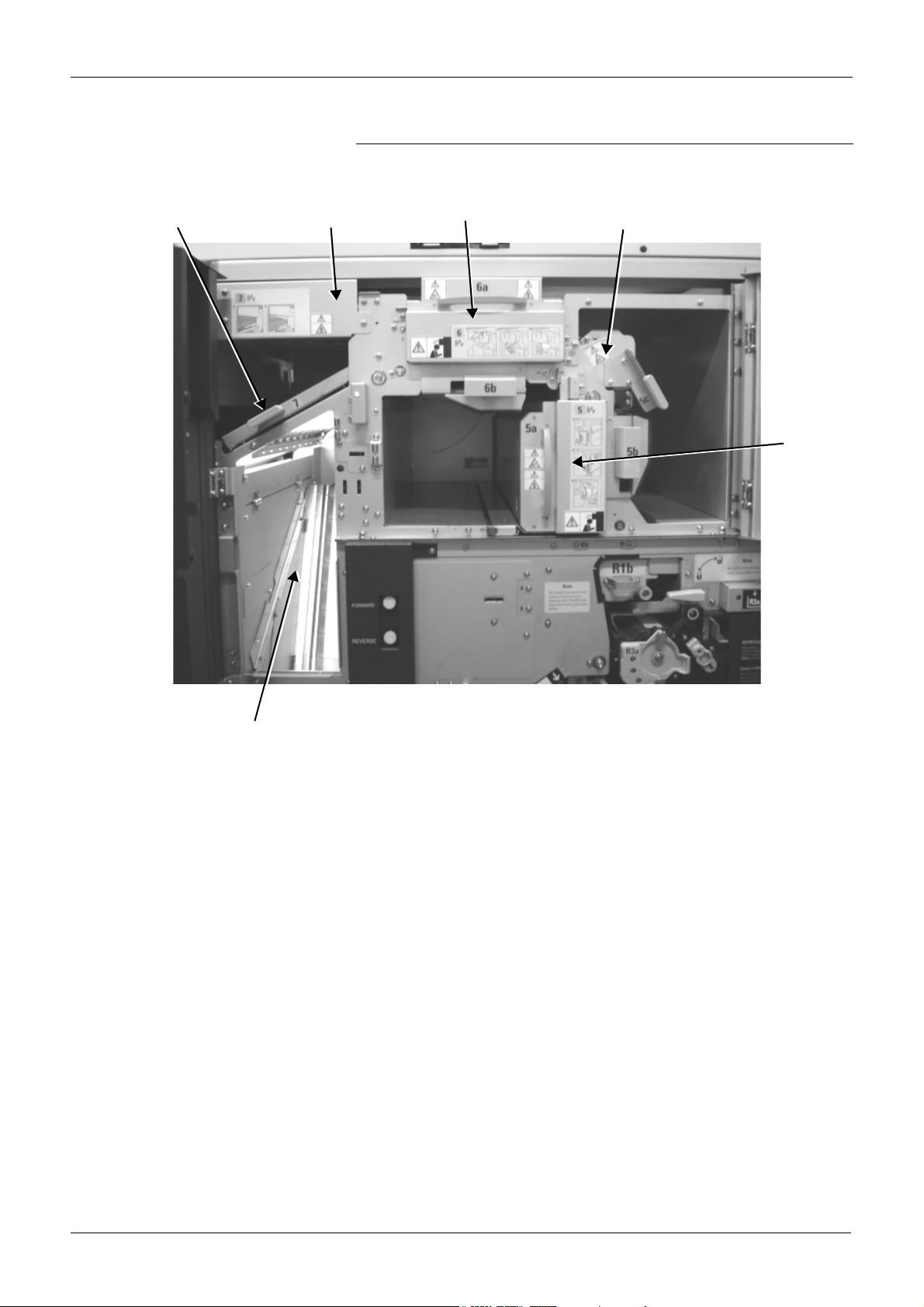
Page 17

PRODUCT OVERVIEW GETTING TO KNOW THE PRINTER ENGINE
Components inside the internal door
The internal door, when opened, provides further access to the
maintenance task components.
Paper Forward/Reverse Switch
Roller Unit A[R1a]
Cleaner Brush Cover
B[R3b]
Cleaner Blade B
Drum Unit B
Developer Entry Port
[R2b]
Transfer Unit A
Roller Unit B[R1b]
Cleaner Brush
Cover A
Cleaner Blade A
Drum Unit A
Developer Entry Port
[R2a]
Ejection Lever A
Transfer Unit B
Ejection Lever B
Developer Discharge Port [R2b]
R Guide
Developer Discharge Port [R2a]
See "Performing routine maintenance" on page 8-1
Xerox 495 Continuous Feed Duplex Printer Operator Guide Page 2-5
Page 18
GETTING TO KNOW THE PRINTER ENGINE PRODUCT OVERVIEW
Components inside the Fuser Door
The Fuser Door, when opened, provides access to the fusing
components.
Fuser Exit Guide
Heater
Fuser A
Autoloader B
Fuser B
Backside Printing
Confirmation Mirror
Page 2-6 Xerox 495 Continuous Feed Duplex Printer Operator Guide
Page 19

PRODUCT OVERVIEW GETTING TO KNOW THE PRINTER ENGINE
Components inside the stacker door
The stacker doors, when opened, provide access to the stacker
components, the smoke filter and the controller PC.
Smoke Filter
Stacker Panel
Paper Tension Lever
Pinch Roller Unit
Paper Output Selector
Stacker Table
Xerox 495 Continuous Feed Duplex Printer Operator Guide Page 2-7
Page 20
GETTING TO KNOW THE PRINTER ENGINE PRODUCT OVERVIEW
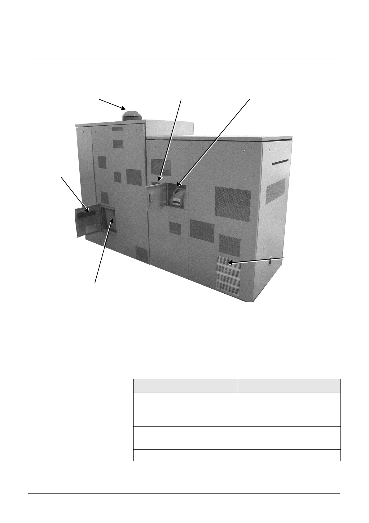
Rear covers and doors
There are two doors at the rear of the printer which provide access to the
waste toner and empty developer containers.
Rear Left Door
Patrol Lamp
Rear Right Door
Empty Developer Container
Vent
Waste Toner Container
The location is referenced as looking from the rear.
•The Rear Left Door provides access to the waste toner container.
•The Rear Right Door provides access to an empty developer bottle
used, when changing developer, to store the used developer before
disposal.
• Patrol Lamp - shows the operational status of the printer as shown
in the following tables:
Status Engine status
Off The engine is powered off, part of
the print line is in a not ready state,
the machine is warming up, in
standby or in maintenance mode.
Green All of the print line is in a ready state.
Red flashing The printer is in error.
Green and yellow flashing One of the consumables is low.
Page 2-8 Xerox 495 Continuous Feed Duplex Printer Operator Guide
Page 21

PRODUCT OVERVIEW GETTING TO KNOW THE PRINTER ENGINE
Paper loading components
The paper loading section components are shown in the following
illustration.
Emergency Power-Off Switch
Autoload Panel
Sub-operator panel (inside door)
Tractor
Assembly
Hopper
Paper Guides
• Sub-operator panel - See “Sub-operator panel” on page 2-28.
• Autoload panel - See “Autoload panel” on page 2-30.
Xerox 495 Continuous Feed Duplex Printer Operator Guide Page 2-9
Page 22
UNDERSTANDING THE TOUCH SCREEN PRODUCT OVERVIEW
Understanding the touch screen
The touch screen has been designed to make your work easier. The
design is intuitive and user-friendly, using colour coding, icons, dialog
boxes, pull-down menus, bubble menus, scroll boxes, buttons, toggle
buttons, tabs and check boxes.
The touch screen gives you fingertip control over the printer. Simply
touch the screen with your finger to move the cursor and select the
various commands.
CAUTION
Always use your finger to make selections. Using pointed items such as
a pencil for selecting buttons on the touch screen may cause permanent
damage to the screen.
Screen symbols
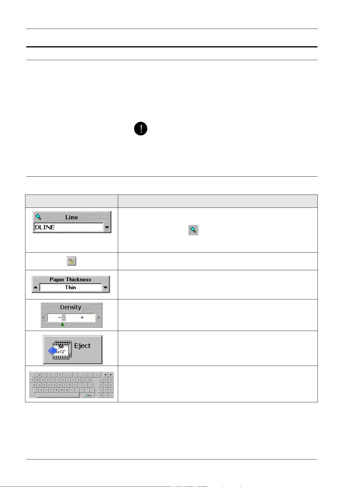
You will find the following symbol types on the touch screen:
Symbol Meaning
Pull-down list - when you press on the arrow a list of the available options is
displayed. Press on the item that you require.
If the list is long, press the and use the keyboard to enter a part of the
item name to quickly locate the item required. If for example, you enter the
letters TE, the list will start at those items beginning with the letters T and E.
Icons - are graphical representations of the status of an item on the touch
screen.
Circular list - when you press on one of the arrows the selection changes to
the next or previous available option in the menu.
Cursor - when you press on one of the arrows, the value is increased or
decreased.
Button - when you press one of these, the indicated operation is activated.
Grayed buttons cannot be selected.
Some buttons, such as the Eject button shown, toggle between states.
Keyboard - used to enter numeric or alphanumeric data.
Page 2-10 Xerox 495 Continuous Feed Duplex Printer Operator Guide
Page 23
PRODUCT OVERVIEW UNDERSTANDING THE TOUCH SCREEN
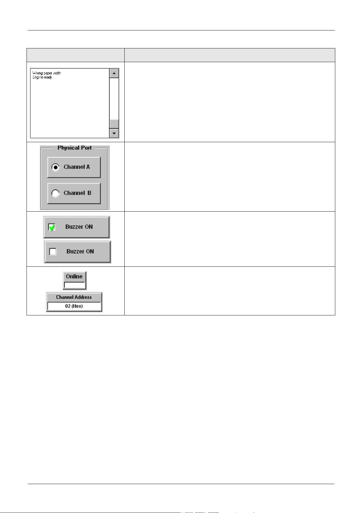
Symbol Meaning
Vertical scrollbar - press on the up or down arrow to scroll one line up or
down. If you keep your finger on the up or down arrow, the screen will scroll
continuously, one line at a time until you remove your finger from the screen.
Press in the space to scroll to the position where you place your finger.
You can also slide the scrollbar by pressing the gray box and dragging it up or
down.
Radio-button - used to select alternative items. Checking the other item will
switch off the current selection.
Check box - used to select items. When the check box contains a tick, the
item is selected.
Display button - shows a value or status of the item.
When you press a display button like the Online button shown, you will toggle
the status.
When you press a display button like the Channel Address button, a further
screen will be displayed allowing you to change the value.
Xerox 495 Continuous Feed Duplex Printer Operator Guide Page 2-11
Page 24
UNDERSTANDING THE TOUCH SCREEN PRODUCT OVERVIEW
Functional areas
The touch screen forms the main control panel of the Xerox 495
Continuous Feed Duplex Printer through which most of the functions and
configurations can be selected. The language of this display can be in
English, French (Français), Italian (Italiano), German (Deutsche),
Spanish (Espanol) or Dutch (Nederlands) by changing the language
through the Users tab.
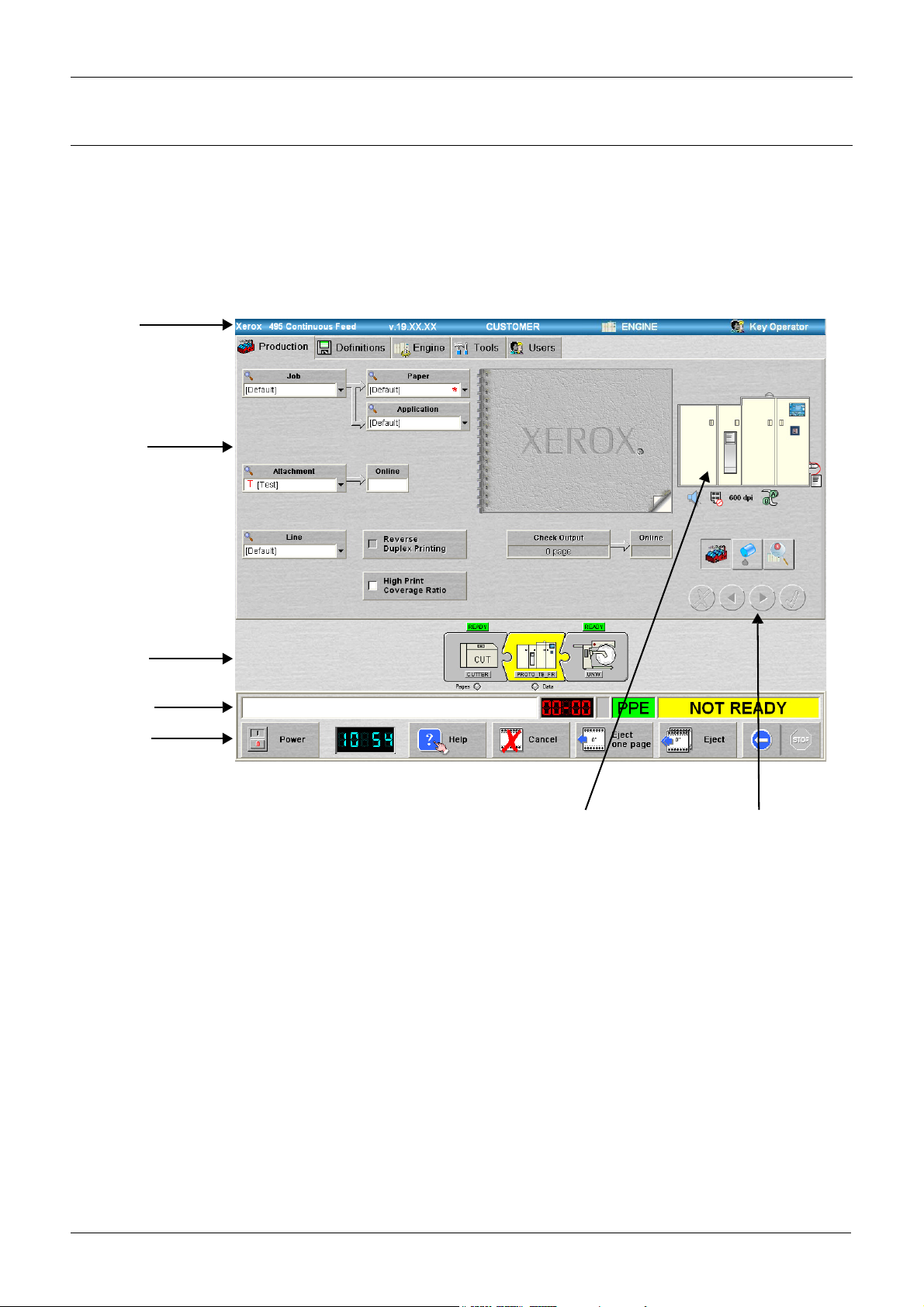
The following illustration shows the functional areas of the touch screen.
Title bar
User Area
Print Line
Status Bar
Action Bar
Printer diagram Navigation buttons
The areas are:
• Title bar See “Title bar” on page 2-13.
• User area See “User area and navigation buttons” on page 2-13.
• Print line See “Print line” on page 2-20.
• Status bar See “Status bar” on page 2-23.
• Action bar See “Action bar buttons” on page 2-25.
• Printer diagram See “Printer diagram” on page 2-26.
• Navigation buttons See “User area and navigation buttons” on page
2-13.
Page 2-12 Xerox 495 Continuous Feed Duplex Printer Operator Guide
Page 25

PRODUCT OVERVIEW UNDERSTANDING THE TOUCH SCREEN
Title bar
Product name, software package
version and customer name
The title bar gives the product name, software package version,
customer name, the name given to the local printer and the current user
role. In three places, there are links to other tabbed pages. These are:
• If you press on the software revision, the Engine > Revisions tab is
displayed (see "Checking software and hardware revisions" on page
9-12).
• If you press on the printer name, the Engine > Config tab is
displayed (see "Making general configurations" on page 3-6).
• If you press on the user role, the User tab is displayed (see
"Changing user roles" on page 3-10).
Printer Name User Role
User area and navigation buttons
The user area will vary according to the navigation button pressed, tab
view selected and user level chosen. Changing the user area will not
affect other areas.
Three views of the user area can be displayed using the navigation
buttons.
• Tab view
• Run view
• Consumables view
Xerox 495 Continuous Feed Duplex Printer Operator Guide Page 2-13
Page 26
UNDERSTANDING THE TOUCH SCREEN PRODUCT OVERVIEW
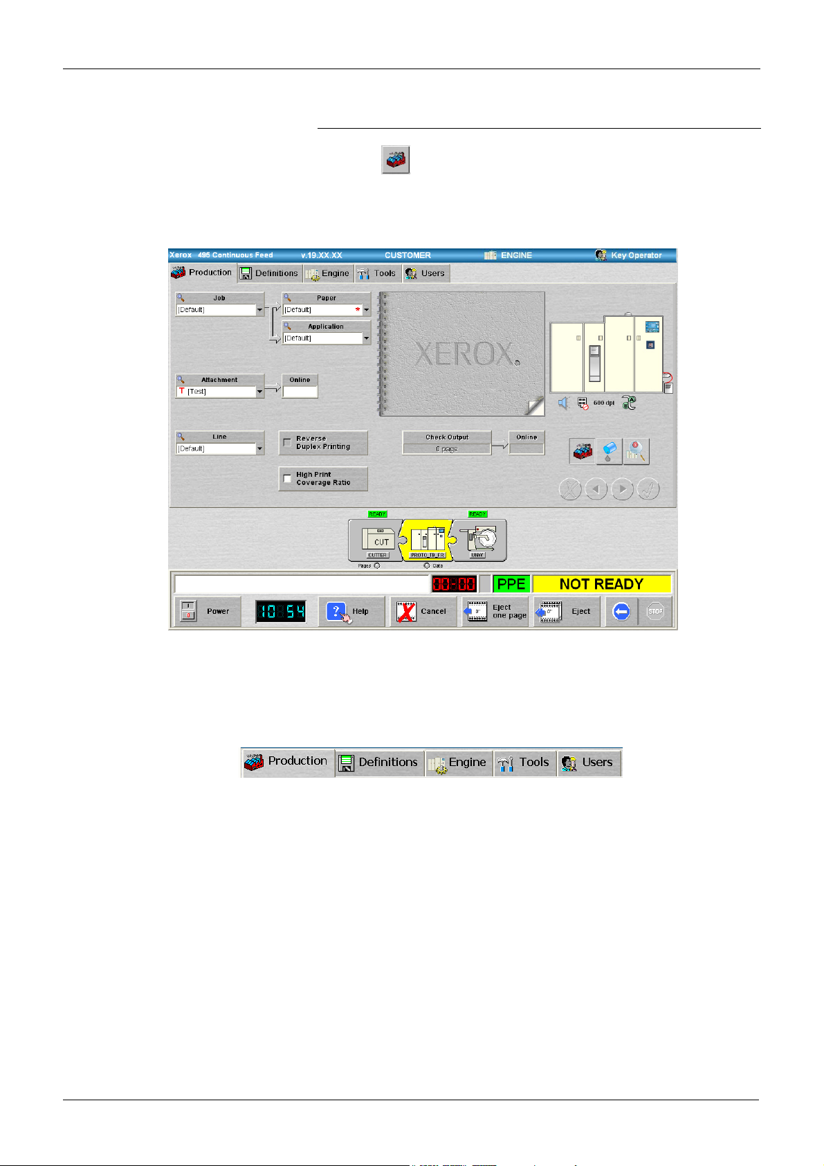
Tab view
Press the button to switch to this view. The default tab view is the
Production tab (see "Running jobs" on page 4-3) which is used to select,
modify and run jobs. The following illustration shows the Production tab
in the tab view.
Each tab view contains the items that can be chosen or set for that
function.
There are five top level tabs some of which will lead to further tabbed
pages.
•Production.
• Definitions.
• Engine.
• Tools.
•Users.
• Option tab (if available, this will bear the name of the installed
option).
Note: An appropriate option tab will be displayed to the right of the
Screen tab once that option has been installed. If, subsequently, the
option license has lapsed, the tab will still appear but will be grayed out.
Page 2-14 Xerox 495 Continuous Feed Duplex Printer Operator Guide
Page 27

PRODUCT OVERVIEW UNDERSTANDING THE TOUCH SCREEN
These five tabs are used to access the different screens as well as
several sub-screens. The following table shows the tab screen structure.
Production Definitions Engine Tools Users
Job Config Test
Paper Print Mode Errors
Size Rev. Resident
Application Lic. Private
Main Status Screen
Offset Update
Density Te st
2-up Process Test
IPDS
or
Line Mode
Line
Paper Path
Device
Marks
Attachment
Channel
TCP/IP
File
Tabs shown in gray are only available for Maintenance and/or Support
users and are not described in this Operator Guide.
Xerox 495 Continuous Feed Duplex Printer Operator Guide Page 2-15
Page 28
UNDERSTANDING THE TOUCH SCREEN PRODUCT OVERVIEW
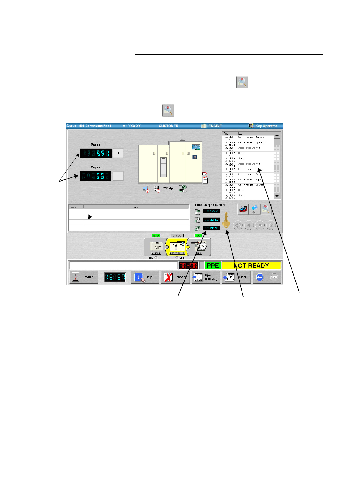
Run view
The Run view logs and displays user actions and activities, error codes
and their labels, resolution, page counters and print charge counters. It is
shown in the following illustration. The button will flash if an error
condition is displayed in the Error Log.
Press the button to switch to this view.
Page Counters
Error Log
Print Charge Counters
Key
Action Log
• Page counters - These page counters increment as you print and
can be used individually for your own individual page counts. The
page counters register each physical page printed and are updated
in units of five pages. Reset these counters by pressing the button
on the right of each one.
• Action log - This displays a list of all those user actions that affect
production:
• Job, Paper, Application, Attachment and Line Selection.
• Actions to Start, Stop or Reset.
• Actions to Cancel or Cancel/Discard Buffers.
• Actions to Eject, Eject One Page.
• Actions within a bubble menu.
• User change (forced or automatic).
• Error messages and their codes.
Page 2-16 Xerox 495 Continuous Feed Duplex Printer Operator Guide
Page 29

PRODUCT OVERVIEW UNDERSTANDING THE TOUCH SCREEN
• Error log - This displays all error codes and their labels, as they
occur. By clicking on an error label, you will immediately access its
accompanying Help. When you press the Reset button, all errors
that have been remedied will be removed from the Error Log.
• Print charge counters - Print charge counters are used to calculate
how much has been printed for a job in order to apply the
appropriate charges. There are three print charge counters; one for
the Front side data printed, a second for the Back side data printed,
and a third for the total of these two (see "Front and back marking
units" on page 2-2).
Note: The display of the print charge counters on the GUI is for
reference only. For a reliable billing meter count, use the mechanical
counter on the sub-operator panel.
• Key - When this key icon is present it means that the print charge
counters (i.e. billing meter) are locked and the counter will not
increment. This feature is for Xerox Service Use ONLY.
Xerox 495 Continuous Feed Duplex Printer Operator Guide Page 2-17
Page 30
UNDERSTANDING THE TOUCH SCREEN PRODUCT OVERVIEW
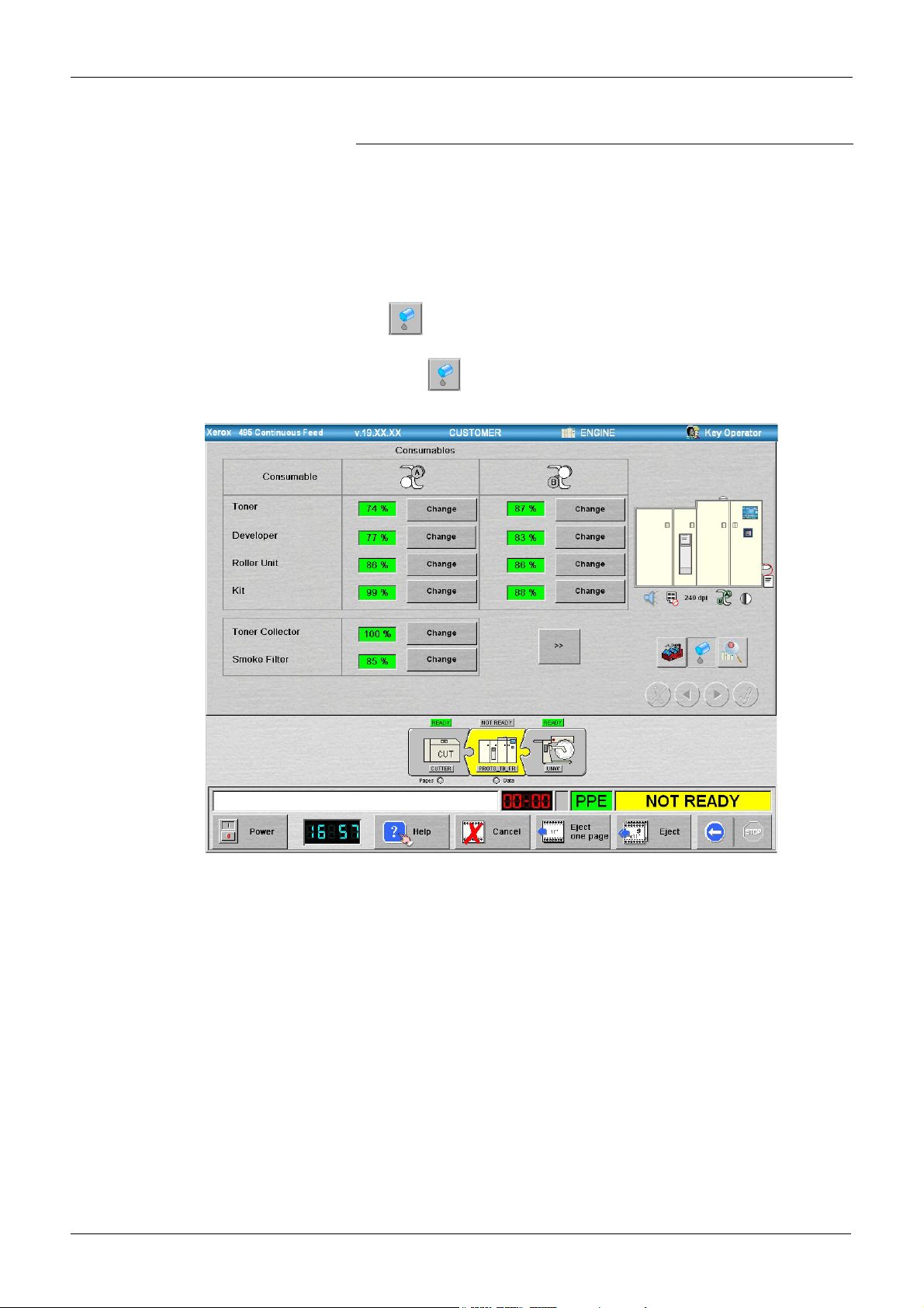
Consumables view
Consumables view - will display one of two consumables screens. The
first shows the usage of all of the consumables that you are able to
replace and provides a means to access the procedures to change that
consumable (see "Checking consumable use" on page 8-4). The second
screen shows the usage of consumables that need to be replaced for
maintenance purposes. This screen is for information only and the
Change buttons are grayed out.
The button flashes if a consumable needs to be replaced.
Press the button to switch to this view. The following illustration
shows the consumables that you are able to replace.
The colour of the value box beside each consumable will change
according to its current condition.
• Green - means that the consumable is in a start of life condition, or
there is sufficient life remaining.
• Orange - means that the consumable is nearing its end of life. An
error message will be displayed from which you can choose to
change the consumable.
• Red - means that the life of the consumable has expired. An error
message will be displayed and, to continue, you will have to change
the consumable.
Page 2-18 Xerox 495 Continuous Feed Duplex Printer Operator Guide
Page 31
PRODUCT OVERVIEW UNDERSTANDING THE TOUCH SCREEN
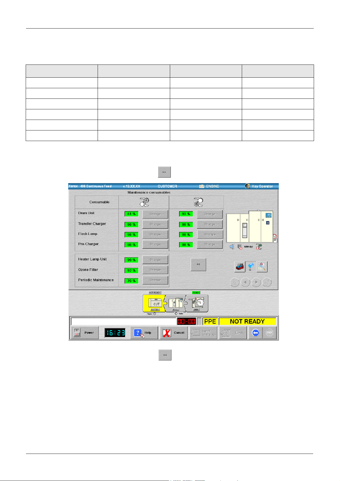
The percentage values shown in the windows have the following
significance.
Consumable Green Orange Red
Toner [Ka] & [Kb] 100% - 18.9% 18.8% - 1% 0%
Developer [R2a] & [R2b] 100% - 10% 9% - 1% 0%
Roller unit A[R1a] & B[R1b] 100% - 10% 9% - 1% 0%
Kit A[R3a] & B[R3b] 100% - 12% 11% - 1% 0%
Toner collector 100% 50% 0%
Smoke filter 100% - 13% 12% - 1% 0%
When several consumables need to be changed simultaneously, there is
no particular order for their replacement.
Press the button to display the maintenance consumables screen.
Press the button to display the consumables that you are able to
replace.
Xerox 495 Continuous Feed Duplex Printer Operator Guide Page 2-19
Page 32

UNDERSTANDING THE TOUCH SCREEN PRODUCT OVERVIEW
Print line
The print line shows a graphical representation of the print line selected
and displayed in the Line field under the Production tab. The following
print line shows a print line composed of a cutter, a printer and an
unwinder.
The Data Lamp indicates the device that receives the data. It will be
green when there is data, red when data is being discarded and grey
when no data is available.
The Pages lamp indicates that there are unprocessed pages remaining
in the paper path. When the Pages lamp is on, an attempt to set the
attachment offline will result in a warning message.
Each graphical representation has four components as shown in the
following illustration.
Status Indicator
Background Colour
Device Icon
Device Name
These are described below.
Status indicator
The status indicator describes the device state and will be green if the
device is Ready or Ready Not Aligned. The device state can be:
• Ready
• Not Ready
•Error
•Soft Stop
• Waiting (Warming Up)
• Off (Engine Power off)
• Maintenance
• Not aligned
Page 2-20 Xerox 495 Continuous Feed Duplex Printer Operator Guide
Page 33

PRODUCT OVERVIEW UNDERSTANDING THE TOUCH SCREEN
Background colour
The device background changes colour and pattern according to the
device state and its alignment condition.”
The device state determines the background colour. The following table
shows the possibilities.
Colour Meaning
Red - The device is in error.
To clear the error, you should refer to the relevant error clearing
procedure in the error help.
Light Gray - The device is in a Ready state.
Note: The background colour is light gray and not green
because it is the normal device state and should not retain the
operator attention. If the colour changes to green and is striped,
then it is ready but not aligned.
Yellow - The device is in a Not Ready state.
You need to make the device Ready by pressing the START
button.
Blue - The device is warming up.
You need to wait a few moments while the device warms up.
Purple - The device is in maintenance mode.
Dark Gray - The device is powered OFF.
You need to power it ON before printing.
Orange - The device is in a soft stop state.
The colour becomes striped when the device is not aligned. The
Xerox 495 Continuous Feed Duplex Printer Operator Guide Page 2-21
Page 34

UNDERSTANDING THE TOUCH SCREEN PRODUCT OVERVIEW
alignment condition changes the background pattern as follows:
Some Devices, such as an unwinder, have no alignment state. These
devices are always considered as aligned.
During a print position check (from start print position check till stop print
position check), the printer device is considered as not aligned.
Device name
For printers, this shows the printer name entered in the Engine>Config.
tab. For pre- and post-processing devices, this displays the name
entered Definitions>Line>Device tab.
Device icon
This illustrates a representation of the device type.
Page 2-22 Xerox 495 Continuous Feed Duplex Printer Operator Guide
Page 35

PRODUCT OVERVIEW UNDERSTANDING THE TOUCH SCREEN
Bubble menu
A bubble menu will be displayed on the screen whenever you press on
a device icon in the print line. The contents of the bubble menu will vary
according to the device selected and the status of that device.
Press on a device representation to display a bubble menu of commands
that can be carried out on that device.
Status bar
Bubble menu command buttons depend on the exact equipment in the
print line (See "Bubble menus" on page 4-11).
The status bar at the bottom of the screen indicates the different states of
the printer.
Description window Option window
Code window
Note: When status is displayed in the
Description window, please call for service or advice.
Pre-/post-processing equipment status window
Printer status window
Xerox 495 Continuous Feed Duplex Printer Operator Guide Page 2-23
Page 36

UNDERSTANDING THE TOUCH SCREEN PRODUCT OVERVIEW
Window Description
Description window Describes the error or current status. The message shown in this window must be
passed on to your service provider when placing a service call.
Code window Gives the current error code (see "Clearing errors" on page 9-2).
Option window Indicates the status of any installed options. The following can be displayed:
Gray box- the option is not present, switched off or the license has expired.
Option icon - an icon representing the option is displayed when the option is installed
and operational.
Pre/post-processing
Equipment Status window
Indicates the status of any pre- and post-processing equipment. If more than one status is present at the same time then they will be displayed in Error, Not Ready and
Ready order.
Gray - pre- or post-processing equipment not present or switched off.
Green steady - ready.
Green flashing - ready, soft stop.
Yellow steady - not ready.
Yellow flashing - not ready, soft stop.
Red - error
Purple - maintenance is taking place.
Printer Status window Indicates the current state of the printer:
READY The printer is ready to print. Press STOP to go Not Ready.
NOT READY The printer is stopped. Press START to go Ready.
ERROR An error has occurred. Correct the problem. Press the RESET
button, then START if needed.
PARAMETERS
CHANGING
This status is displayed when you change some of the printer
parameters.
ENGINE OFF The printer engine is off. Press the POWER button to power
on the engine.
WARMING UP The developer and drum units are being initialized. Please
wait a few minutes.
AUTOLOAD The printer is loading paper.
CONNECTING The touch screen is establishing a network link to the control-
ler. Please wait a few minutes. If, after 5 minutes, the connection fails, a pop-up message will be displayed.
PRINTING A job is in progress.
EJECTING The printer is in the process of ejecting paper.
BUSY The printer is between statuses.
MAINTENANCE The printer is undergoing maintenance.
Page 2-24 Xerox 495 Continuous Feed Duplex Printer Operator Guide
Page 37
PRODUCT OVERVIEW UNDERSTANDING THE TOUCH SCREEN
Action bar buttons
The buttons at the bottom of the screen are used to control your printer.
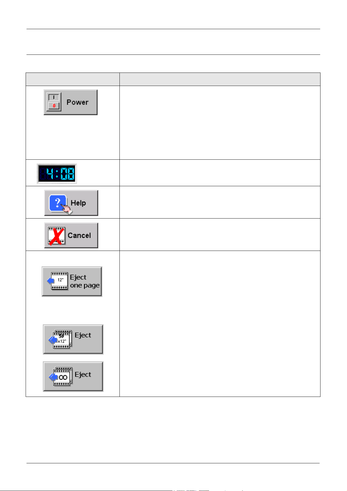
Button Description
Power button - used for powering the printer engine on and off. When the
engine is powered on, the button shows this state and the green LED is lit.
When powered off the LED is red.
There are two power states:
Power on/off - where the engine and the controller are on or off. This is carried out at the Sub-Operator Panel.
Engine on/off - where the engine is on or off. This is carried out at the touch
screen using this button.
Do not press the Power button to stop printing. For emergency stop, use the
Emergency switch (see "Autoload panel" on page 2-30).
Clock - displays the time in 24 hour format.
Double pressing on the clock will open a dialog to adjust the time. This will
affect the time on the GUI and in the controller.
Help button - provides access to the on-screen help system. See "Using
help" on page 3-5.
Cancel button - cancels the job in progress. This could be a print job from the
host or when a Print Position Check is in progress. See "Cancelling jobs" on
page 4-14.
Eject buttons
Eject one page button - press this button to eject a single sheet.
Eject pages button - this is a toggle button that switches between two eject
states. Press and hold down the button for two or three seconds to toggle
between the eject states. The eject states are:
Eject the number of sheets shown (50 in the illustration). The number of
sheets to eject will be determined when creating the line definition for a job
(see "Defining a paper path" on page 7-21).
In systems with pre-/post-processing devices, this will be the distance
between devices determined at installation.
The number of sheets changes to the infinity sign and, once pressed, this will
continue to eject paper until the STOP button on the touch screen is pressed.
Xerox 495 Continuous Feed Duplex Printer Operator Guide Page 2-25
Page 38

UNDERSTANDING THE TOUCH SCREEN PRODUCT OVERVIEW
Button Description
START button - used to set the printer ready.
STOP button - used to set the printer to not ready.
Reset button - used for indicating that an error condition has been cleared.
This button replaces the START/STOP button.
Printer diagram
The Printer diagram is an animated representation of the printer.
The patrol lamp in the representation will indicate the status of the
machine.
• Off - The engine is powered off, part of the print line is in a not ready
state, the machine is warming up, in standby or in maintenance
mode.
• Green - All of the print line is in a ready state.
• Red flashing - The printer is in error.
• Green and yellow flashing - One of the consumables is in a low
state.
Press a closed door to open it and show the paper path behind that door.
If an error condition occurs, the doors in the printer diagram will
automatically open to show the location of the problem. Press anywhere
behind an open door to close all open doors.
Page 2-26 Xerox 495 Continuous Feed Duplex Printer Operator Guide
Page 39

PRODUCT OVERVIEW UNDERSTANDING THE TOUCH SCREEN
Under the printer diagram, you will find the following icons:
• - This icon means that the buzzer is activated. When it is
crossed , it means that the buzzer is not activated. See
“Making general configurations” on page 3-6.
• - This icon means that a high print coverage ratio is selected.
When it is crossed , it means that a high print coverage ratio
is not selected. See “Running jobs” on page 4-3.
• - This icon shows that the resolution set in the current
application definition is 240 dpi. Change the resolution to another
resolution (300 or 600) and this icon also changes . See
“Defining applications” on page 7-12.
• This icon shows the marking units active for the current job
(see "Setting print modes" on page 3-8). If you choose and print a
simplex job, only the A marking unit will be highlighted. If printing in
duplex and have print mode switching enabled after a specified
number of pages, the icon does not change.
• - This icon appears when you select a density that is not the
default setting. It is a type of warning and does not appear when
using the default density. See “Notebook density settings” on page 4-
8.
Xerox 495 Continuous Feed Duplex Printer Operator Guide Page 2-27
Page 40

OPERATOR PANELS PRODUCT OVERVIEW
Operator panels
There are a number of additional operator panels. These are:
• Sub-operator panel
• Autoload panel
• Stacker panel
• Paper forward and reverse switch panel
Sub-operator panel
The sub-operator panel is behind the small door at the upper part on the
right side of the printer. Open the small door to use the panel.
Counter
Power
Alarm
Power
Name Function
Remote
Local
The components are shown in the following table:
button
Turns the printer power on.
button
Turns the printer power off.
Remote/Local switch
Determines whether to turn the printer on and off using the On and Off buttons (Local) or
from and external control (Remote) (see "Remote powering on and off" on page 3-3).
On
Off
Counter sw
Page 2-28 Xerox 495 Continuous Feed Duplex Printer Operator Guide
Page 41

PRODUCT OVERVIEW OPERATOR PANELS
Name Function
Counter This mechanical counter is incremented every 26" of printing. In duplex printing, front and
back side prints are counted separately and the combined totals are displayed. The
mechanical counter will count every 26" of print length and the Xerox billing system will list
total meter "clicks" and show the charger per 26" click. The customer must multiply by
2.17 to get the actual linear feet used.
Counter switch The counter switch is for Xerox Service Use ONLY. It is used to lock and unlock the
mechanical counter.
ALARM
(Display)
INPUT - Indicates that printer power supply is abnormal.
LV1 - Indicates that the input control power supply (LV1) is abnormal.
LV2 - This LED is not used.
FV1 - Indicates that the flash power supply (FV1) is abnormal.
FV2 - Indicates that the flash power supply (FV2) is abnormal.
XCOV - Indicates that the fuser-related protective door is open.
THA1 - This LED is not used.
THA2 - Indicates that the control unit temperature is abnormal and the printer will shut
down. You must disconnect then reconnect the main power from the printer to extinguish
this LED
EPO - Indicates that the Emergency Power Off switch has been operated.
UPC - Indicates that the UPC is abnormal.
Xerox 495 Continuous Feed Duplex Printer Operator Guide Page 2-29
Page 42
OPERATOR PANELS PRODUCT OVERVIEW
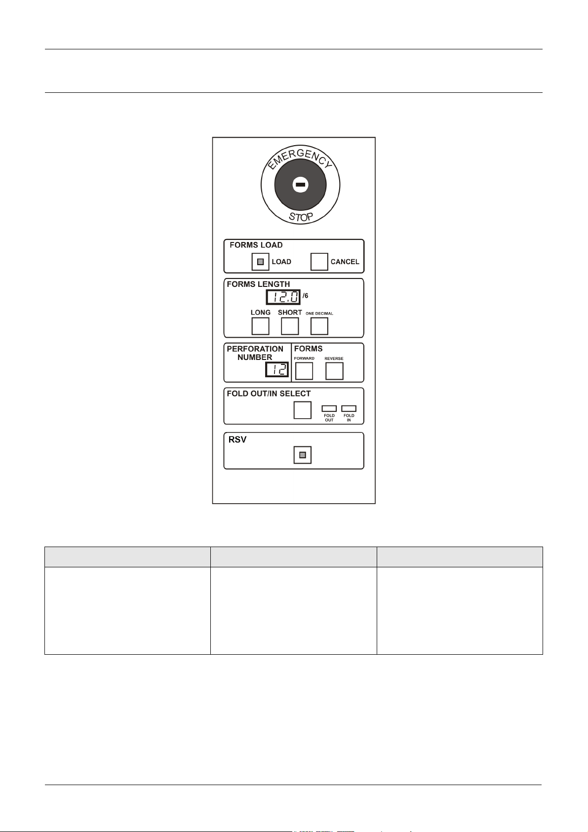
Autoload panel
The autoload panel is used to load paper automatically and can be found
at the right side of the printer.
The components are shown in the following table:
Name Function Effectiveness
Emergency switch Hit this switch to stop the printer
Effective always.
engine and paper handling devices
in the event of an emergency. It
requires a key to reset.
The emergency switch is for emergency use only. Using this switch
may destroy data in the system.
Page 2-30 Xerox 495 Continuous Feed Duplex Printer Operator Guide
Page 43

PRODUCT OVERVIEW OPERATOR PANELS
Name Function Effectiveness
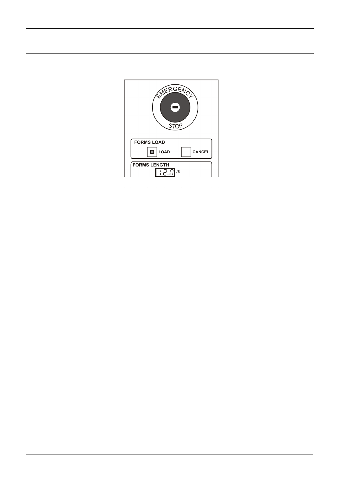
Forms Load Load
Feeds paper automatically to the
stacker table when pressed with
paper set on the tractor. This function is called autoload.
The main operator panel displays
“Autoloading” If paper is set up to the
stacker, the paper width is measured. Then the main operator panel
displays “Measuring paper width”.
Cancel
Press this switch to stop autoloading
immediately.
Forms Length Sets the length of the form in inches.
The display will show the value
entered. Any changes made here
will change the perforation number.
Long
Increments the units by 1 for each
press of the button.
Short
Decrements the units by 1 for each
press of the button
One decimal
Increments the decimal position by
1/6 inch for each press of the button
Perforation number Defines the position of the perfora-
tion on the tractor scale.
Forms Forward
Feeds paper 1/6” (4.2mm) toward
the stacker.
Holding down this switch feeds the
paper continuously.
Reverse
Feeds paper 1/6” (4.2mm) toward
the hopper.
Note: For complete data fusing,
press this switch to align perforation.
Note: If the forward / reverse button is pressed during a job (Data LED on),
the printer considers that the operator wants to realign the position of the
paper, and therefore discards data buffers and report a sense to the host.
The host will then re-send the pages.
Fold-out/in select Selects the swing guide direction.
This switch is used to select fold-out/
in at perforation before autoloading
and after a paper jam is removed
and the paper length is aligned with
the tractor scale.
The corresponding lamp will indicate
the setting.
RSV Reserve switch
Effective when the printer is not
operating. While the paper is auto-
matically being loaded, the LED of
this switch remains lit.
Effective during autoloading.
Effective when the printer is not
operating and has no paper inside.
Effective during autoloading.
Effective when the printer is not
operating
Effective when the printer is not
operating
Effective when the printer is not
operating
Xerox 495 Continuous Feed Duplex Printer Operator Guide Page 2-31
Page 44

OPERATOR PANELS PRODUCT OVERVIEW
Stacker panel
The stacker panel is at the top of the stacker. Open the right stacker door
on the front of the printer to use the stacker panel.
Paper output
selector lever
Stacker Panel
Paper tension
lever
The components are shown in the following table:
Name Function
Printer Start switch This has the same function as the Start button on the touch screen (see page 26).
Printer Stop switch This has the same function as the Stop button on the touch screen (see page 26).
Printer Reset
This has the same function as the Reset button on the touch screen (see page 26).
switch
Table Auto switch Automatically lifts the table to the height suitable for paper folding. Then the paper guide
moves to the set level. If this is operated when printing, an error will occur.
When the paper output selector lever does not have the stacker selected, it is disabled.
Table Stop switch Stops lifting or lowering the stacker table. If this is operated when printing, an error will
occur.
When the paper output selector lever does not have the stacker selected, it is disabled.
Table Down switch Lowers the stacker table. The paper guide opens to the specified position and stops. If this
is operated when printing, an error will occur.
When the paper output selector lever does not have the stacker selected, it is disabled.
Paper output selector lever
Page 2-32 Xerox 495 Continuous Feed Duplex Printer Operator Guide
Used to select whether the paper will be output to the stacker or to another post-processing device.
Page 45

PRODUCT OVERVIEW OPERATOR PANELS
Name Function
Paper tension lever Select the position of the lever according to requirements as follows:
Lever position Use
Standard Ordinary printing
(Weak) Using special paper
Release Removing a paper jam
The lever is set to the weak position when using special paper.
Paper forward and reverse switch panel
The Paper Forward/Reverse switch is at the upper part on the front of the
printer.
Name Function Effectiveness
Forward Feeds paper 1/6” (4.2mm) toward the stacker.
Holding down this switch feeds the paper continuously.
Effective when the
printer is not operating
Reverse Feeds paper 1/6” (4.2mm) toward the hopper. Effective when the
printer is not operating
Note: These switches have the same functions as the Paper Forward
and Reverse switches on the autoload panel.
Xerox 495 Continuous Feed Duplex Printer Operator Guide Page 2-33
Page 46

PRE- AND POST-PROCESSING EQUIPMENT PRODUCT OVERVIEW
Pre- and post-processing equipment
Paper input to the printer may come from a pre-processing device such
as an unwinder or from a paper box at the hopper.
Paper that has been processed can be delivered to an external postprocessing device such as a cutter, folder or rewinder.
Page 2-34 Xerox 495 Continuous Feed Duplex Printer Operator Guide
Page 47
PRODUCT OVERVIEW THE PRINT LINE BUS (PLB)
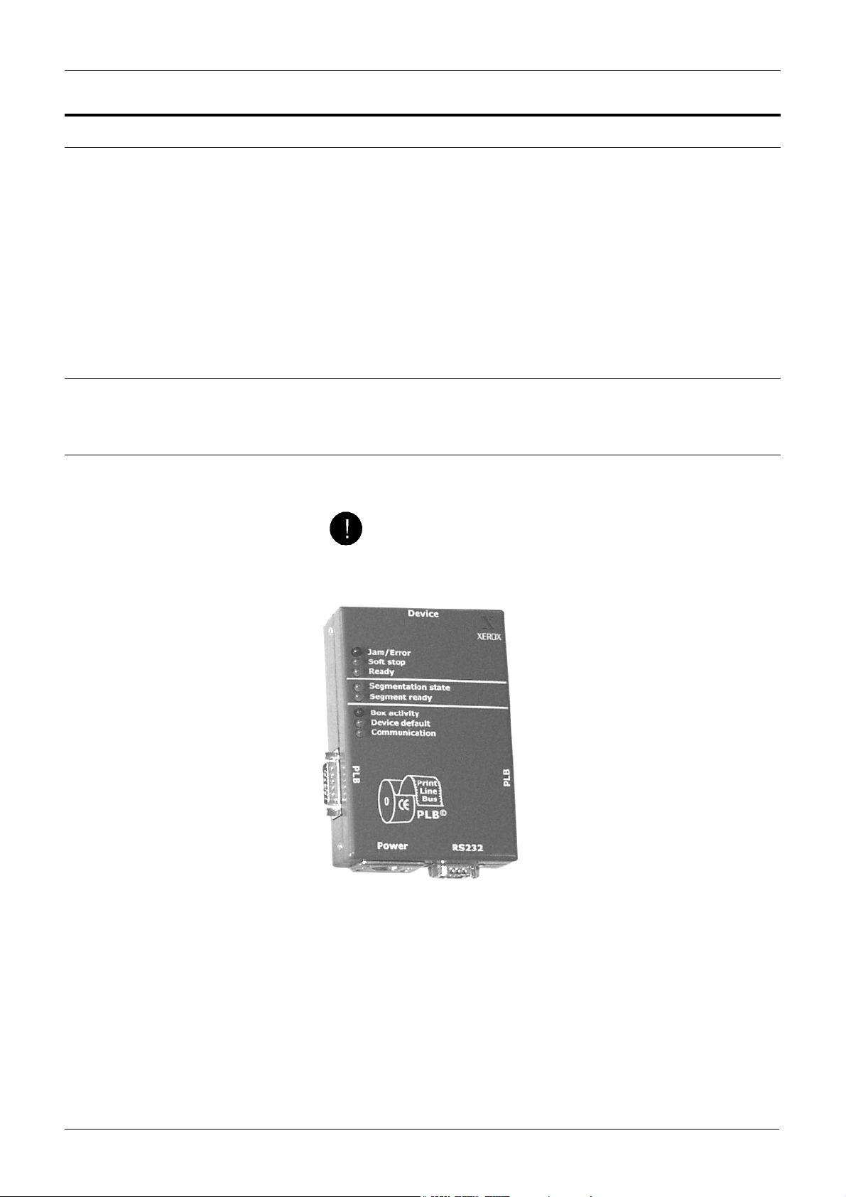
The Print Line Bus (PLB)
The Print Line Bus (PLB) connects all devices in a defined print line. It is
made up of PLB boxes connected to each other. Each PLB box is also
connected to a single device.
The PLB box is unique to the device to which it is attached. This can be
pre- and post-processing devices as well as printers.
The defined print line or print line segment will comprise a number of
devices, all connected through the PLB. A print-line segment comprises
only one data master, but can have several paper masters. All devices in
a given print-line segment have to be available for the segment to be
selected.
Identifying the PLB boxes
Each PLB box is identified by a unique hexadecimal code which is
configured into the system at installation.
Cabling the PLB
Each cable must match the device to which it is attached. These will be
correctly installed at installation of the printing system.
CAUTION
Using the wrong cable could cause damage to the equipment.
The PLB box has five connectors. Each PLB box must be connected to
the next PLB box through the PLB network cable connected at either
side of the box. Both end PLB boxes are terminated with a PLB
terminator.
Each PLB Box is linked to its device through a dedicated cable through
the Device connector.
Each print line segment is powered at only one PLB box. Power is
supplied to the PLB box from a low voltage power supply and is
transferred to the rest of the PLB boxes through the PLB network cables.
Xerox 495 Continuous Feed Duplex Printer Operator Guide Page 2-35
Page 48

THE PRINT LINE BUS (PLB) PRODUCT OVERVIEW
It doesn’t matter which PLB box in the print line segment provides the
power for the PLB, however, each print line segment must have only one
source of power.
The RS232 connection is used by support personnel to maintain the PLB
box. It is also used by the printers to carry communications data.
Characteristics
The maximum length of PLB cable between the first PLB box and the last
is of 100 metres (330 feet).
Up to 10 PLB boxes can be networked on the PLB.
Segmentation
The segmentation of the print line is possible through the PLB.
Segmentation is the ability to assemble devices in a number of ways to
form the print line required. Each device available in the print room is
connected to its PLB box. All PLB boxes are linked together.
The idea of segmentation is to allow you to define as many print lines as
you require, according to the devices available. These print line
definitions can then be recalled at any time. See "Defining a paper path"
on page 7-21.
Each print line has to be defined under a separate name. For example:
• cutter line 1
• folder line 2
Note: You should name each print line clearly enough to be able to
recognize it easily. It may be useful to label each device so as to be sure
that all devices required by a defined print line are suitably prepared for
the job. For example if the unwinder defined by the print line is not ready,
it will show the status not ready and no work will be produced.
Page 2-36 Xerox 495 Continuous Feed Duplex Printer Operator Guide
Page 49
PRODUCT OVERVIEW LICENSING
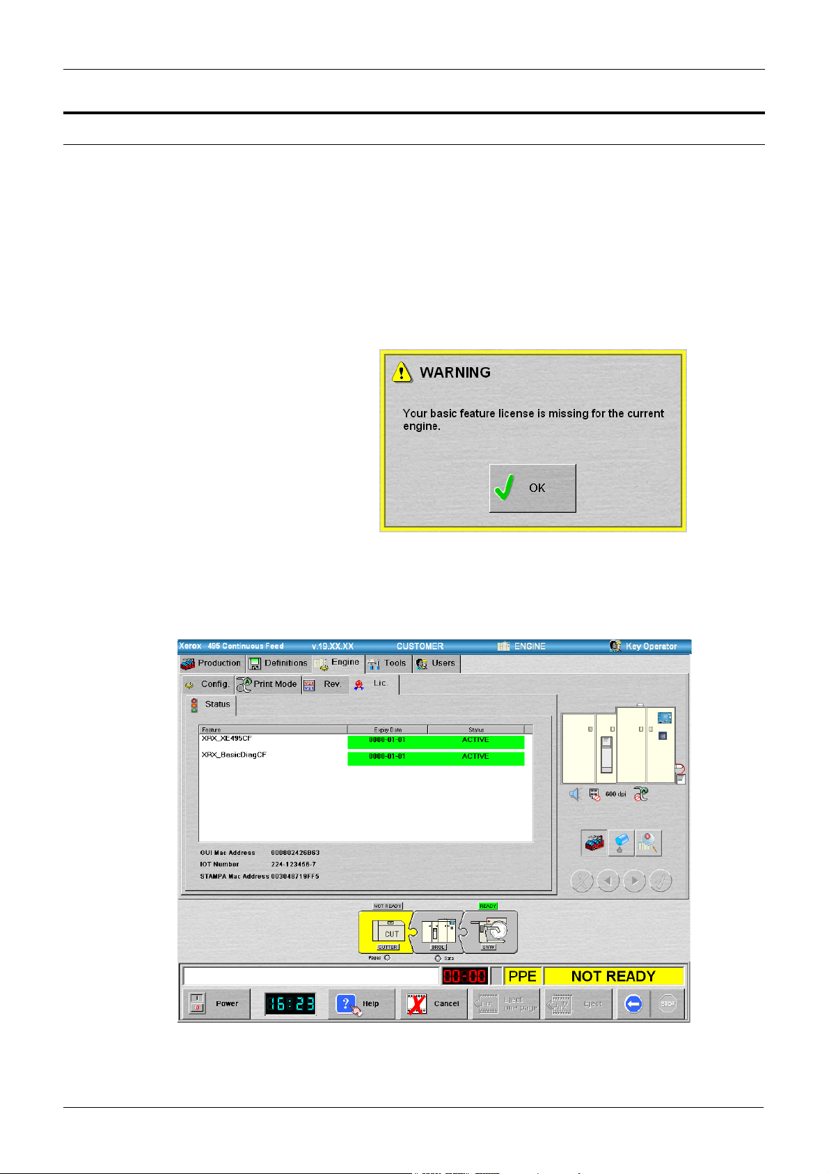
Licensing
There are two licenses associated with the Xerox 495 Continuous Feed
Duplex Printer:
• XRX_XE495CF - Without this license the printer is prevented from
operating. The license enables you to put an attachment online, to
start a job and to make a software upgrade.
• XRX_BasicDiagCF - Without this license access to engine
diagnostics will not be available to Maintenance or Support users.
When a license has expired and you try to put an attachment on line, the
following message will be displayed.
Thirty days before the license expires, a warning will be displayed when
Start is pressed after a four hour period.
You can view the status of the licenses on the system from the
Engine>License>Status tab.
Xerox 495 Continuous Feed Duplex Printer Operator Guide Page 2-37
Page 50

LICENSING PRODUCT OVERVIEW
The table is divided in three columns.
• Feature - If there is a feature name in the current license.dat, the
name will appear in this column.
• Expiry Date - This column displays the expiry date of the license for
each feature recognized.
• Status - The licenses can either be:
• Active: the license is operational. These licenses are denoted
by a green background.
• Expiring: the license for this feature is still operational for
maximum of 30 days. These licenses are denoted by an orange
background.
• Expired: the license for this feature has expired. These
licenses are denoted by a red background.
• Wrong: the license file has been altered. These licenses are
denoted by a white background.
• Invalid: the license file does not correspond to the printer.
These licenses are denoted by a red background.
• Wrong version: the license file does not correspond to the
software package version. These licenses are denoted by a red
background.
Renewing the license
You should check the expiry of your licenses on a regular basis.
Contact your dealer to renew your licenses.
Page 2-38 Xerox 495 Continuous Feed Duplex Printer Operator Guide
Page 51
3. Getting started
This chapter tells you:
• How to switch the printer on and off including emergency stop
procedures.
• How to use the on-line help provided at the touch screen.
• Making general configurations
• Setting Print Modes
• How to change your user role.
WARNING
Operator tasks identified in this chapter should only be completed
if the required training has been given to enable the tasks to be
completed without risk or injury.
WARNING
When completing any of the tasks in this chapter, observe all
applicable warnings as indicated in the user precautions.
WARNING
When the printer is ready, it is under the control of the attached
host system and can start without warning.
Xerox 495 Continuous Feed Duplex Printer Operator Guide Page 3-1
Page 52

SWITCHING THE PRINTER ON AND OFF GETTING STARTED
Switching the printer on and off
Power to the printer can be switched on at the sub-operator panel (Local)
or remotely (Remote) from an external device.
Local power on and off
To switch on the printer:
1. Check that the main power switch is set to ON. The main circuit
breaker is situated to the rear of the machine, close to the power
cable in the bottom left-hand corner.
2. Open the small door on the right panel to access the sub-operator
panel.
Counter
Alarm
Power
On
Off
Counter sw
Remote
Local
3. Make sure the REMOTE/LOCAL switch is set to LOCAL.
4. Press , the POWER ON switch on the sub-operator panel.
The touch screen goes through self tests before displaying the user
interface.
Note: This could take several minutes.
The printer warms up.
5. Switch on any pre- and post-processing devices following the
instructions in the appropriate User Manual.
To switch off the printer:
Page 3-2 Xerox 495 Continuous Feed Duplex Printer Operator Guide
Page 53

GETTING STARTED SWITCHING THE PRINTER ON AND OFF
This procedure switches off the printer engine and the controller. To
switch off the engine only, press the Power button on the Production
screen.
Notes:
When turning the power off, check that the green lamp of the fuser is lit. It
takes up to four and a half minutes until the green lamp at the fuser
lights.
If the power is turned off immediately after printing, paper may be
scorched at the fuser. (Even after printing, the cooling fan will operate to
cool the fuser. Once the fuser temperature has reached a safe level, the
green lamp at the fuser lights.)
Do not attempt to power the printer off when the data lamp is green or
during economy mode switching. Doing so will result in errors when you
power the printer back on.
1. Ensure that all jobs are finished.
2. Press the STOP button on the touch screen to set the printer to Not
Ready.
3. Switch the Attachment offline by pressing the Online button.
Remote powering on and off
4. Open the small door on the right panel to access the sub-operator
panel.
5. Press , the POWER OFF switch on the sub-control panel.
6. Switch off the mains power isolator (circuit breaker), if necessary.
7. Switch off any peripheral devices following the instructions in the
appropriate User Manual.
Provision is made for a master device to remotely power on and off a
printer where the main power isolator is turned on. This is only possible
where the master device is physically connected to the printer through a
connector provided for the purpose, when the REMOTE/LOCAL switch
on the sub-operator panel is set to REMOTE and the master device
activates the correct signals.
Three signals are used:
• Power Pick will cause the printer to power up until a power ready
signal is received.
• Power Hold maintains power on until it is deactivated.
• Power Ready is generated by the printer to signal to the master
device that it is powered on.
Both Power Pick and Power Hold must be activated to power the printer
on.
Xerox 495 Continuous Feed Duplex Printer Operator Guide Page 3-3
Page 54
SWITCHING THE PRINTER ON AND OFF GETTING STARTED
Emergency stop
The emergency stop is a strike button mounted above the autoload panel
on the right end door of the printer engine.
This will force the engine to turn off immediately and execute a controlled
shutdown for the controllers.
After being activated, a key is needed to reset it.
If a pre- or post-processor is attached to the printers emergency power
off loop, operating the emergency power of switch on the device will also
cause a shutdown.
Page 3-4 Xerox 495 Continuous Feed Duplex Printer Operator Guide
Page 55

GETTING STARTED USING HELP
Using help
Your printer has built-in help, which can be accessed in a number of
ways:
1. In the form of a book with a table of contents leading you to the
procedure you want to carry out. This is accessed by pressing the
button.
The links to the procedures are shown in green and underlined.
Navigate to the required procedure by pressing the appropriate link.
Press the Table of Contents link to start the navigation through the
help.
You can use the and keys to scroll through the different
pages, the key to return to the initial page and the key to
close the help and display the last tabbed page that you used.
2. Help in clearing Error Messages. This can be accessed from the
Run view or from the Status bar by pressing the error message.
Some of these help screens have links to the relevant section under
the Help tab. See “Clearing errors” on page 2.
3. Operational help when replacing consumables is provided when you
are in the Consumables View and you press the Change button for
the consumable. Successful replacement of consumables relies on
you following these help instructions in the sequence they appear.
See “Checking consumable use” on page 4.
Xerox 495 Continuous Feed Duplex Printer Operator Guide Page 3-5
Page 56

MAKING GENERAL CONFIGURATIONS GETTING STARTED
Making general configurations
For each printer engine, the Key Operator can give the printer a name
and switch the warning buzzer on or off. In addition, the Support user can
enter a Customer name to be displayed in the title bar.
To make general configuration changes:
1. Press the to make the printer engine Not Ready.
2. Select the Engine tab, then the Config. tab.
The Configuration screen is displayed.
3. Select the Printer Name field.
A keyboard is displayed. Type in the name of the printer that you
want to see in the title bar.
4. Check the Buzzer ON box to activate the buzzer which will sound in
the event of an error. This will show the buzzer icon as activated
below the printer diagram.
Page 3-6 Xerox 495 Continuous Feed Duplex Printer Operator Guide
Page 57

GETTING STARTED MAKING GENERAL CONFIGURATIONS
Setting the time on the screen
The time displayed on the screen can be changed. This will change the
time in the controller and on the screen.
To change the time:
1. Press on the time section of the display.
A time adjust dialog will be displayed.
2. Press the + button to increment the time by 1 minute or the - button
to decrement the time by 1 minute.
3. Continue until you have the desired time displayed.
4. Press to confirm, or to discard changes.
Xerox 495 Continuous Feed Duplex Printer Operator Guide Page 3-7
Page 58

SETTING PRINT MODES GETTING STARTED
Setting print modes
Note: The counters referred to in this section are located in the Run view
(touch screen) and not the mechanical counter on the sub-operator
panel. The mechanical counter counts drum rotations and not pages.
The Print Mode tab is provided to enable or disable the following print
mode features:
•The Both Side Printing Enabled box – when checked, this enables
duplex printing.
•The Print Mode Switching Enabled box – when checked, this
reduces lost production due to the time it takes to switch between
duplex and simplex mode.
•The Economy Mode box - when checked, this will remember the
mode of the last job before power off and start up in the same mode.
If this box is not checked, the printer will power up in duplex mode.
This feature is only available if Print Mode Switching has been
enabled.
The choice is a balance between economy of time and economy of
printer consumables.
Setting print modes can be done in the following three different ways:
1. Both Side Printing enabled and Print Mode Switching disabled
• When a duplex job is received, the printer prints in duplex mode and
2 pages are added each time to the counter.
• When a simplex job is received, the printer prints in simplex mode
but, because both engines are running, 2 pages are added each
time to the counter.
2. Both Side Printing disabled and Print Mode Switching disabled
• When a simplex job is received, the printer prints in simplex mode
and, because only one engine is running, 1 page is added each time
to the counter.
• When a duplex job is received, the printer goes into error and cannot
print. This is because only one engine is running. To correct the
error, manually activate Both Side Printing. The printer will start to
print as soon as the second engine is ready.
3. Both Side Printing enabled and Print Mode Switching enabled
• If you check the Print Mode Switching Enabled box, press the
Number of Simple Side Forms Before Print Mode Switching box and
enter the number of pages (10 is the minimum). When you enter a
number that is not a multiple of 10, it will be rounded up to the next
multiple of ten (8 will become 10, 12 will become 20).
• When a duplex job is received, the printer prints in duplex mode and
2 pages are added each time to the counter.
• When a simplex job is received after a duplex job, the printer will
continue to print in duplex mode for the number of pages shown in
the window before switching into simplex mode.
Note: Duplex mode in this case means that the simplex data will be
printed and the back page data will be blank.
The printer adds 2 pages each time to the counter until it reaches the
Page 3-8 Xerox 495 Continuous Feed Duplex Printer Operator Guide
Page 59

GETTING STARTED SETTING PRINT MODES
indicated number. The printer will then stop, cutting the second
engine. After approximately. one minute, the printer will restart in
simplex mode and 1 page will be added each time to the counter.
• When a duplex job is received after a simplex job, the printer will
stop and then initialize the second engine. This can take up to 6
minutes. Once printing, 2 pages will be added each time to the
counter.
• If the value is zero, then simplex mode is disabled.
To set the print mode:
1. Select the Engine tab, then the Print Mode tab.
The Print Mode screen is displayed.
2. Check the boxes required.
If you check the Print Mode Switching Enabled box, press the
Number of Simple Side box and enter the number of pages to be
printed before switching into simplex mode.
Xerox 495 Continuous Feed Duplex Printer Operator Guide Page 3-9
Page 60

CHANGING USER ROLES GETTING STARTED
Changing user roles
There are four user roles defined: Operator, Key Operator, Maintenance
and Support. When the machine is first switched on or after a timeout
period specified for all other users, touch screen access reverts to the
Operator User. All users other than Operator have a password controlled
access to the facilities available.
Note: The current user role is shown on the top right of the screen.
The Timeout column shows the duration for which, Maintenance or
Support users get access to their respective tasks. These times are set
at the values shown (one hour and four hours respectively).
The Key Operator can provide access to the Notebook for the Operator
to make changes that affect the paper and application settings defined
for a job See “Setting locked components” on page 11.
To change your user role:
1. Select the Users tab.
The Users screen is displayed which is used to define the role and
passwords for different types of users.
2. Press the button in the User column that is appropriate to the user
role wanted.
3. Press the appropriate button in the Password column if the access
required is Key Operator, Maintenance or Support.
4. Enter your password using the keyboard and press the
button.
Page 3-10 Xerox 495 Continuous Feed Duplex Printer Operator Guide
Page 61

GETTING STARTED CHANGING USER ROLES
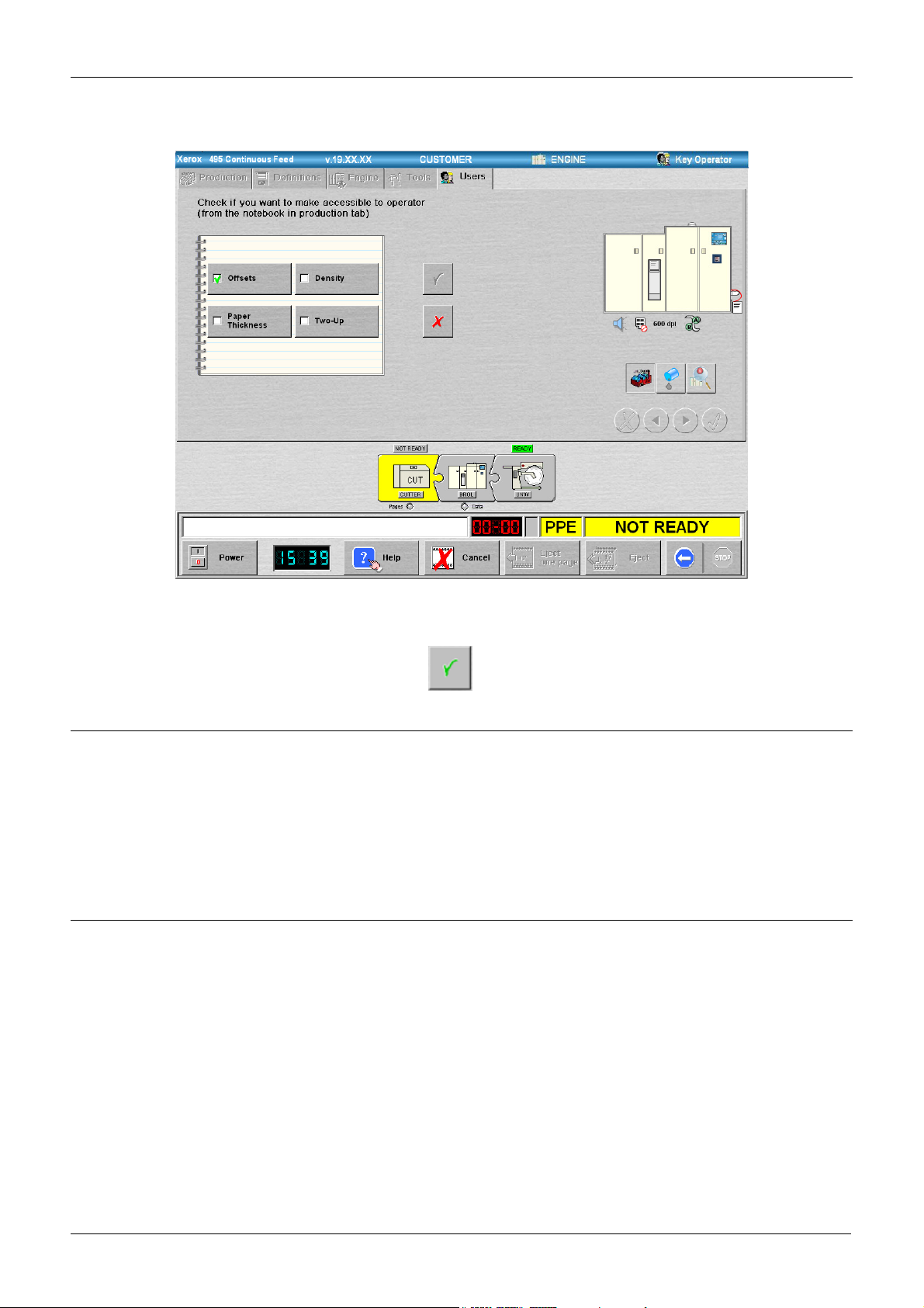
Setting locked components
The notebook can be locked or unlocked by Key Operators in order to
prevent Operator access to any or all features available in the Notebook.
When the machine starts up for the first time, the Notebook will be closed
with the cover displayed.
To change Operator access:
1. Select the Users tab.
The Users screen is displayed.
2. Press the Key Operator button and enter your password.
3. Press the button.
The screen which allows additional operator access to features is
displayed.
Xerox 495 Continuous Feed Duplex Printer Operator Guide Page 3-11
Page 62
CHANGING USER ROLES GETTING STARTED
Changing the password
Changing the user language
4. Check each box where you want to allow operator access to the
Notebook.
5. Press .
To change your password:
1. Change to your user role and enter your existing password.
2. Press the password button corresponding to your role.
3. Enter and confirm your new password.
The next time that you change to your role, you will need to use the
new password.
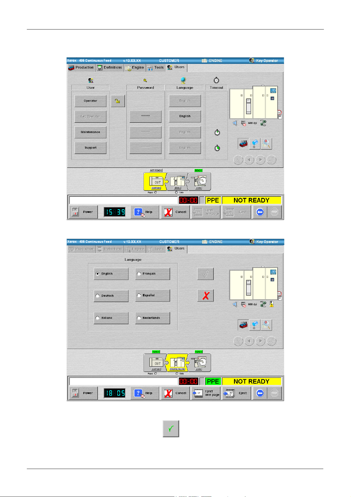
The language of this display can be in English, French (Français), Italian
(Italiano), German (Deutsch), Spanish (Espanol) or Dutch (Nederlands).
Each user can select their own language.
1. Select the Users tab.
Page 3-12 Xerox 495 Continuous Feed Duplex Printer Operator Guide
Page 63
GETTING STARTED CHANGING USER ROLES
The Users screen is displayed.
2. Press the Language button.
3. Choose the language.
4. Press .
Xerox 495 Continuous Feed Duplex Printer Operator Guide Page 3-13
Page 64

CHANGING USER ROLES GETTING STARTED
Page 3-14 Xerox 495 Continuous Feed Duplex Printer Operator Guide
Page 65

4. Running production jobs
This chapter describes the procedures used for running production jobs.
The contents are:
• Quick start - a checklist for experienced Operators.
• Running jobs - step-by-step instructions.
• Cancelling jobs
WARNING
Operator tasks identified in this chapter should only be completed
if the required training has been given to enable the tasks to be
completed without risk or injury.
WARNING
When completing any of the tasks in this chapter, observe all
applicable warnings as indicated in the user precautions.
WARNING
When the printer is ready, it is under the control of the attached
host system and can start without warning.
Xerox 495 Continuous Feed Duplex Printer Operator Guide Page 4-1
Page 66

QUICK START RUNNING PRODUCTION JOBS
Quick start
The following is a simplified method for starting a new job.
Note: You should follow the full procedures if you are new to the printer
or unsure of what to do.
1. Eject the paper and remove the completed job from the output
device if you want to use a paper different from the one currently
being used.
If the paper has been output to a pre- or post-processing device see
the appropriate user manual.
If you are feeding paper from a box or an unwinder that is not empty,
cut the paper (See “Cutting paper” on page 5-11.).
2. Load the paper (See “Paper Loading” on page 5-3.).
3. Select the print line that you want to use.
4. Select a previously defined job on the Production screen (see
"Running jobs" on page 4-3).
5. Check that the parameters shown on the screen are correct (see
"Running jobs" on page 4-3).
6. Set the Output Check value, if required (see "Setting the Check
Output value" on page 4-9).
7. Start printing.
8. Stop as soon as the first pages are printed and check the alignment,
margins and print quality.
9. Start the printer again after making any necessary adjustments.
Page 4-2 Xerox 495 Continuous Feed Duplex Printer Operator Guide
Page 67

RUNNING PRODUCTION JOBS RUNNING JOBS
Running jobs
1. Select the Production tab.
The Production screen is displayed. This is the normal screen when
printing and will be the opening screen. The facilities on this tab are
available to all users.
Note: The Notebook area in the illustration shown below has been
unlocked by the Key Operator enabling Operator level users to
adjust a number of items relating to the job to be run. See “Changing
the notebook settings” on page 4-6.. When the notebook is
unlocked, the bottom right corner is turned over as shown in the
illustration below.
The screen shows a number of indicators and settings used for
printing.
From this screen you can call up a pre-defined job configuration,
select and enable the attachment for the job and choose the
appropriate print line. You can also modify the job configuration to
use a different pre-defined paper or application.
Notebook Area See “Changing the notebook settings” on page 4-6.
Paper List
Printer Diagram
Job List
Application List
Attachment List
Online
Button
Line List
High Print
Coverage Ratio
box
Check Output
value
Pages Lamp
Reverse
Duplex
Printing
Box
Check
Output
Enable
Button
Print
Line
Data Lamp
The components of the screen are:
• Job pull-down list - this is used to choose the name of the job
previously defined under the Definitions>Job tab. An asterisk
(*) is displayed to the right of the job name for any modification
made to the job definition. An 'x' is displayed to the left of the
appropriate selection for any modification to the Paper, or
Xerox 495 Continuous Feed Duplex Printer Operator Guide Page 4-3
Page 68

RUNNING JOBS RUNNING PRODUCTION JOBS
Application definitions with respect to their original
configuration.
Note: Before you can switch between Job and Application, you
must first select OFFLINE for Attachment.
• Paper pull-down list - this is used to choose the name of the
paper previously defined under the Definitions>Paper tab. An
asterisk (*) is displayed to the right of the name for any
modification made to Paper Thickness value through the
Notebook or through the Definitions tab.
• Notebook area - the notebook area can display a number of
pages that can be used to redefine Paper and Application
settings. These pages are only available if permission has been
allowed by the Key Operator See “Changing the notebook
settings” on page 4-6.
• The Printer Diagram shows any possible fault areas and
highlights those where action is required.
• The Reverse Duplex Printing box is checked when it is
necessary to print the back on the first marking unit and the
front on the second (see "Front and back marking units" on
page 2-2).
• Check Output - shows the number of pages to be printed in
order to check the output (see "Setting the Check Output value"
on page 4-9).
• Check Output Enable - When the conditions to enable the
Check Output feature are available, this button will be active
(see "Setting the Check Output value" on page 4-9).
• Print Line - this shows the composition of the chosen print line
and the status of each of the items of equipment that form the
print line. If you press on an item, a bubble menu will be
displayed. The bubble menu is used to select actions to be
taken (see "Bubble menus" on page 4-11).
• Data Lamp - indicates the device that receives the data (data
master). It will be green when there is data, red when data is
being discarded and gray when no data is available.
• Pages Lamp - indicates that there are unprocessed pages
remaining in the paper path.
• The High Print Coverage Ratio box is checked in order to
reduce paper wrinkle in the following circumstances:
When printing with a long interval between a pause and a restart.
With high-density printing near the bottom of the last page at a
printing stop.
Thin paper or other kinds of paper easy to wrinkle.
When checked, this switches on a feature in the printer engine.
The check box cannot be changed when the printer is in Ready
mode and is grayed out.
Note: The throughput may go down when printing intermittently
because it takes time to heat paper.
The power consumption and heat under control or under no
control differ from those in ordinary mode.
Paper transport at the stop sequence in high printing rate mode
Page 4-4 Xerox 495 Continuous Feed Duplex Printer Operator Guide
Page 69

RUNNING PRODUCTION JOBS RUNNING JOBS
is solely done by the printer and not recognized by the host
computer. Therefore, if a paper jam occurs, a duplicate page
may be printed as the recovery page.
• Line pull-down list - this is used to choose the name of the Line
system previously created under the Definitions > Line tab.
The print line will change to reflect the components of the
chosen line and the status of each of the components.
Note: You must deselect the attachment before you choose a
new line.
• Attachment pull-down list - this is used to choose the name of
an attachment type previously created under the Definitions >
Attachment tab. Once an attachment is enabled, you cannot
change the line.
Note: Attachments that use the TCP/IP protocol are shown with
the TCP/IP symbol and those that use the Channel are shown
with the Channel symbol. These symbols are shown in the
following illustration.
TCP/IP symbol Channel symbol
• Application pull-down list - this is used to choose the name of
the application definition previously created under the
Definitions > Application tab. Changing the emulation or
paper width checked box in the Definitions > Application tab
displays an asterisk (*) on the Production tab.
Note: You cannot change from an application that is defined for
one-up printing to an application that is defined for two-up
printing without first draining the host system or disabling the
attachment.
• Online indicator and button - this will be green if the printer is
connected to the system or white if the printer is disconnected
from the system. Press the button to switch between the two.
There will be a slight delay when changing the online state while
the controller updates.You need to deselect this before
changing the print line to be used.
Note: By changing from Online to Offline in certain conditions,
the following phenomena occur.
Changing to offline during connecting to host causes that the
connection is reset and host may resend the job from first page.
Changing to offline during print position check mode causes the
cancellation of print position check mode without returning to
original printing position.
2. Select the Print Line that you want to use.
3. Choose the Job from the pull-down list.
4. Choose the Attachment host and press the Online button.
5. Reset the Page Counter, if necessary. You will be asked to confirm
your decision.
6. Make any adjustments to the Notebook area if necessary and
available.
Xerox 495 Continuous Feed Duplex Printer Operator Guide Page 4-5
Page 70

RUNNING JOBS RUNNING PRODUCTION JOBS
7. Check that the correct paper is loaded in the printer (see "Paper
Loading" on page 5-3).
8. Set the Check Output value.
9. Press the button to set the printer to a ready state.
The job will be printed once the host has sent it.
Changing the notebook settings
Notebook settings are provided to change certain parameters set in a job
definition.
Note: You can only change settings here if you are the Key Operator, or
if the Key Operator has provided you with access. If access is allowed,
the bottom right corner of the notebook is folded over as shown in the
illustration below.
Notebook
Unlocked
Indication
If the Notebook area is available, it comprises four pages. You can
change pages by pressing the folded corner.
Page 4-6 Xerox 495 Continuous Feed Duplex Printer Operator Guide
Page 71
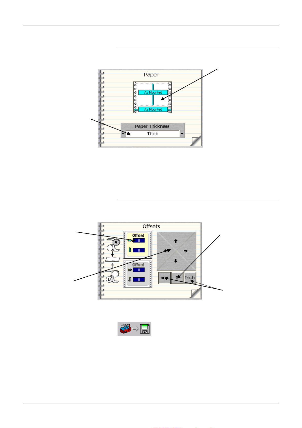
RUNNING PRODUCTION JOBS RUNNING JOBS
Notebook paper settings
The paper settings page of the notebook deals with the settings for the
different grades of paper and is shown in the following illustration.
Paper Size button
Paper Thickness
circular list
Paper Size button - displays the paper size defined for the job.
Paper Thickness circular list - is used to choose the paper thickness
(thin or thick). An asterisk (*) is displayed to the right of the Paper pulldown list for any modification to the paper thickness with respect to the
original configuration.
Offset display
Offset arrows
Notebook offsets
This page of the notebook deals with adjusting the page offset for each
marking unit. It is shown in the following illustration.
Reset offset to zero button
Offset unit buttons
To save the changes you make to the offset in the Notebook, you have to
import them into the Definitions>Application>Main tab by pressing the
button to import the application parameters from the
current Production screen.
For each marking unit, Front A or Back B (see "Front and back
marking units" on page 2-2).
Offset arrows - are used to define the positioning of data on the page in
the direction shown by the arrow. For each click of the arrows, the offset
increments / decrements in units of 0.1mm or 0.01 inch in that particular
direction. An asterisk (*) is displayed to the right of the Application pull
Xerox 495 Continuous Feed Duplex Printer Operator Guide Page 4-7
Page 72

RUNNING JOBS RUNNING PRODUCTION JOBS
down list for any modification to the margins with respect to the original
configuration.
The settings can be entered in millimeters or inches by pressing the
corresponding buttons. The 0 button resets the offset to 0. The settings
made will be displayed in the Offset display to the right of the arrows.
Notebook density settings
This page displays a density cursor for both sides of the paper and is
used to set the image density for both sides. There are five density levels
which are pre-defined by the Key Operator under the Definitions >
Application > Density tab (See "Defining applications" on page 7-12).
Offset print density cursor
Each press of an arrow key will step the cursor through the five predefined density levels for the selected side in the direction pressed.
Notebook 2-up settings
This page of the notebook deals with 2-up printing. The 2-up printing
page is shown in the following illustration.
Two-up choice display
The 2-up choice display shows how 2-up has been defined for the
application.
If 2-up is selected, the offset can be changed in inches or in millimeters
for each side depending on the setup defined in the Application tab.
Press the required direction arrows in the appropriate Offset button to set
the offset between -0.5” and +0.5” or -0.1mm and +0.1mm.
Page 4-8 Xerox 495 Continuous Feed Duplex Printer Operator Guide
Page 73

RUNNING PRODUCTION JOBS RUNNING JOBS
Offset buttons allow you to precisely position on the sheet where the
logical pages (data) will be printed. This is especially useful when using
pre-printed paper.
The left offset button is used to position the logical page on the left side
of the sheet.
The right offset button is used to position the logical page on the right
side of the sheet.
Note: In Definitions, you cannot change from an application that is
defined for one-up printing to an application that is defined for two-up
printing without first draining the host system or disabling the attachment.
Any changes made in the Notebook take immediate effect, without first
having to drain the host system or disable the attachment.
Press to view or amend the back side or to view or amend
the front side.
Setting the Check Output value
The Check Output feature allows you to define a number of pages to
print in order to visually check their layout before printing the whole job.
The printer stops as soon as the requested number of pages has been
printed.
1. Make sure that the Check Output Online button is enabled.
The Check Output Online button and the counter are enabled when the
line is NOT READY and the attachment is online.
By default, the counter displays the value of the previous number of
pages entered, even after a power OFF/ON. However, if there was no
previous setting, the counter is set to a value of 5.
2. If the number of pages to print for preview is correct, skip ahead to
Xerox 495 Continuous Feed Duplex Printer Operator Guide Page 4-9
Page 74
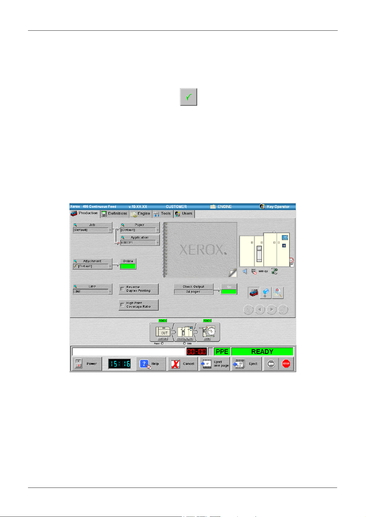
RUNNING JOBS RUNNING PRODUCTION JOBS
step 7.
3. If the number of pages to print for preview needs to be modified,
press the counter button. This opens a touch screen keyboard.
4. Enter the number of pages to be printed (between 1 and 999).
5. Press the button.
6. Alternatively, press the Cancel button to keep the value of the
previous number of pages.
You will return to the Production tab, the number of pages to be printed
will be displayed inside the counter, and the feature is enabled.
7. Press the Check Output Online button to activate the feature. The
button will become green and the counter will gray out. To deactivate
the feature, press the Online button again.
8. Set the printer to Ready in order to start printing.
When READY and/or printing, the Check Output Online button remains
green but is not accessible and the counter remains grayed out.
9. When the print job is started, the counter decrements while printing
and refreshes on a regular basis.
10. When the print job is finished, a notification dialog is displayed to
signify that the number of pages that were selected have been
Page 4-10 Xerox 495 Continuous Feed Duplex Printer Operator Guide
Page 75

RUNNING PRODUCTION JOBS RUNNING JOBS
printed. The counter is reset to its original setting.
11. Press the button to return to the state where the
feature is enabled and accessible but not active. The printer goes
back to NOT READY.
Bubble menus
A bubble menu will be displayed when you press on a component in the
print line diagram. The menu contents will vary according to the
equipment chosen.
The menu contains action buttons and status indicators. The action is
carried out when you press the appropriate menu item.
The following illustration shows the bubble menu for the printer.
Xerox 495 Continuous Feed Duplex Printer Operator Guide Page 4-11
Page 76

RUNNING JOBS RUNNING PRODUCTION JOBS
Bubble menu possibilities
Bubble menu command buttons depend on the exact equipment in the
print line. The following bubble menu command buttons are available for
the printer.
• Toggle button Start Print Position Check / Stop Print Position
Check:
• Start Print Position Check - When you press this button, paper
is forwarded to the stacker and the stacker automatically lowers.
This allows you to check the printing status on the stacker table.
• Stop Print Position Check - When you press this button, the
paper reverses to its original printing position.
The Start / Stop Print Position Check procedure is:
1. Set the printer to Not Ready. Print line device background = yellow.
Status window = yellow.
2. Press the Start Print Position
Check button.
Paper is forwarded to the stacker.
Print line device background = striped yellow/white.
Status window = green.
The stacker automatically lowers. The printer falls into error.
Print line device background = striped red/white.
Status window = red.
You can now check the printing status on the stacker table.
3. Press the Stacker Auto button. The stacker raises.
4. Press the RESET button to clear
the error.
Print line device background = striped yellow/white.
Status window = yellow.
Not Aligned displayed on the printer icon.
5. Press the Stop Print Position
Check button.
The paper reverses to its original printing position.
Print line device background = yellow.
Status window = yellow.
6. Set the printer to Ready. Print line device background = green.
Status window = green.
The following bubble menu command buttons are available, depending
on the device configuration.
• Eject button - This button will only work for the device from which
the eject is requested. This action will also take the printer out of
alignment. Press the button for as long as you want the printer to
eject paper. As the paper will only move in the selected device, there
are risks of paper breaks. Always make sure there is enough paper
available for the eject, or that the paper is cut. To do an eject for the
whole line, you should use the eject button in the action bar on the
screen.
• Release button - This button allows you to release paper to empty a
whole part of the line. When you release paper, all devices
downstream from the one that starts the release are in a state that
allows them to move paper. Therefore, if you choose Release from
the Unwinder bubble menu, all the paper in the print line will move.
Note: There exists the following limitation around the pre-processor
in a release situation. It is possible to press the Release button when
the pre-processor is off, Unwinder, for example. The problem is that
Page 4-12 Xerox 495 Continuous Feed Duplex Printer Operator Guide
Page 77

RUNNING PRODUCTION JOBS RUNNING JOBS
if you go to the bubble menu and press Release when the Unwinder
is powered off, the paper will start moving and finally provoke a jam,
because it breaks or tears.
• Load or Load & Align - This action is usually performed when
installing new paper, after changing paper, or after clearing a paper
jam/break. The Load button will appear for devices that do not need
to be aligned, (folders, for example). The Load & Align button will
appear for devices that do need to be aligned, (cutters, for example).
• Print Alignment - This button will be available for all devices that
need to be aligned. The procedure requires that the whole line is in a
Ready state. It is typically used when paper has been previously
loaded but not aligned or when paper has lost alignment due to an
error or user operation for example. Pressing the button will start the
alignment procedure.
• Aligned - Once the device is aligned, you must confirm the aligned
status by pressing the Aligned button.
• Not Aligned - If the device is not aligned, you must declare the line
not aligned by pressing the Not Aligned button.
• Aligned/unjammed - This button is used to declare the
postprocessors Ready when aligned or unjammed.
• Not aligned/jammed - This button is used to declare the
postprocessors Not Ready due to misalignment or paper jam. Press
the button to perform the action.
Xerox 495 Continuous Feed Duplex Printer Operator Guide Page 4-13
Page 78
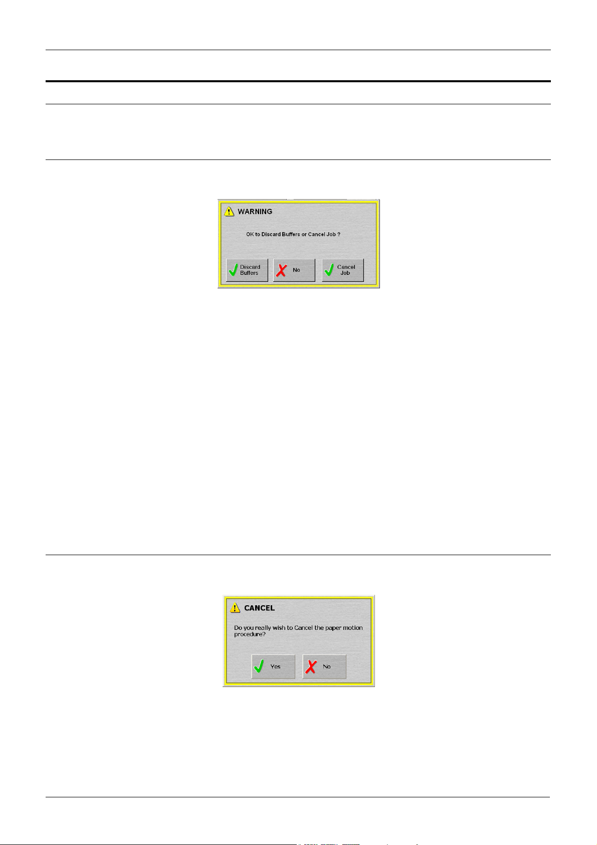
CANCELLING JOBS RUNNING PRODUCTION JOBS
Cancelling jobs
The Cancel button is used to interrupt print jobs from the host system or
to cancel a Print Position Check.
Cancelling a print job
When the Cancel button is pressed during a print job, the following
dialog box will be displayed:
• Press the Discard Buffers button to stop the current print job and
discard all pending print buffers from the printer leaving the job in the
host job queue. If no forward or backward commands are made at
the host system then the host will resume printing at the next page
once the printer is ready again.
Cancelling a print position check
This procedure is used when you need to stop the current print job to
reposition it or when a print alignment is interrupted due to an error
and does not resume after the error is corrected. In this case, the
bubble menu will remain empty as the print alignment is not
considered to be terminated.
• Press the Cancel Job button to cancel the job currently being
printed. Then set the printer to Ready. The printer reports the cancel
to the host system in order to delete it from the host job queue. To
restart the job you will have to resubmit it. This procedure is used
when you need to stop the current print job and want to delete it from
the host job queue.
• Press the No button if you do not want to cancel the print position
check.
When the Cancel button is pressed during a print position check, the
following dialog box will be displayed:
• Press the Yes button to cancel the print position check.
• Press the No button if you do not want to cancel the print position
check.
Page 4-14 Xerox 495 Continuous Feed Duplex Printer Operator Guide
Page 79
5. Paper path
This chapter describes how to load paper into the printer and how to
make adjustments to the paper path components.
WARNING
Operator tasks identified in this chapter should only be completed
if the required training has been given to enable the tasks to be
completed without risk or injury.
WARNING
When completing any of the tasks in this chapter, observe all
applicable warnings as indicated in the user precautions.
WARNING
When the printer is ready, it is under the control of the attached
host system and can start without warning.
Xerox 495 Continuous Feed Duplex Printer Operator Guide Page 5-1
Page 80
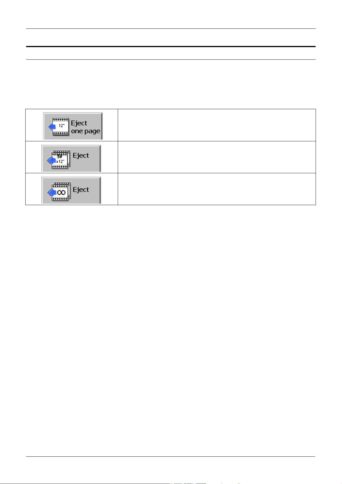
EJECTING PAPER FROM THE PRINTER PAPER PATH
Ejecting paper from the printer
Ejection can take place using either of the Eject buttons on the action bar
at the bottom of the touch screen. In addition, you can eject paper using
a selection from the bubble menu associated with a device.
The Eject button only works for the device from which the eject is
requested and affects the whole print line. The possibilities are:
The Eject one page button moves the paper on by one sheet for each press.
The multi page eject button moves the paper on by the number of sheets displayed (30 in the illustration) for each press.
The number of pages to be ejected when the button is pressed will be the
distance between devices determined at installation.
The infinite eject button will continue to eject paper until the STOP button on
the touch screen is pressed, even if the stacker is not ready or full.
Note: To switch between the multi page and infinite eject states, press
the button for a few seconds until the button changes to the state that
you require.
The bubble menu possibility is Release which is available for any paper
master device on the line and will move sufficient paper to clear the print
line from that device onwards. Therefore, if you choose Release from the
Unwinder bubble menu, all the paper in the print line will be moved. You
can release paper by pressing the appropriate icon on the print line and
choosing Release from the bubble menu.
Page 5-2 Xerox 495 Continuous Feed Duplex Printer Operator Guide
Page 81

PAPER PATH PAPER LOADING
Paper Loading
Paper loading is a two-stage procedure.
1. The paper is loaded on the hopper.
2. The paper is autoloaded.
Loading on the hopper
To load paper in the hopper:
1. Remove the paper from the printer (see "Removing Paper" on page
5-12).
2. Check that the stacker components are in the following state:
• There is no paper left on the stacker table and the Table Auto
switch is set.
• The paper tension lever is set at a suitable position for the new
paper.
• The paper output lever is correctly set.
3. For paper supplied from a box, place the paper box under the hopper
and press it against the paper box guides.
Hopper
Paper Box
Paper Box Guide
• Turn the knob on the right-side guide to loosen it.
Knob
Paper Box Guide
Paper
Xerox 495 Continuous Feed Duplex Printer Operator Guide Page 5-3
Paper Registration Position
Right Side
Guide
Page 82

PAPER LOADING PAPER PATH
• Press the right-side guide against the right side of the paper
box.
• Turn the knob to secure the right-side guide.
4. For paper coming from a pre-processing device, feed the paper to
the hopper.
Paper autoloading
Autoloading moves the paper from the hopper and positions it ready for
printing.
To autoload the paper:
1. Prepare the leading edge of the paper as shown in the following
diagram.
Paper weight below 82gsm
Fold back one sheet
Paper edge
Paper weight above 82gsm
Paper edge
Note: If you get an autoload error repeatedly with the same paper, check
that the first perforation is not protruding too far. If so, flatten it a little to
ease the folding. Make sure, however, that the perforation is not too flat
or folded in the opposite direction because stacking performance or
other problems may occur.
Fold-out perforation
Fold-out perforation
Page 5-4 Xerox 495 Continuous Feed Duplex Printer Operator Guide
Page 83

PAPER PATH PAPER LOADING
2. Thread the paper through the decurler and brush.
Supplementary table
Supplementary table lever
Decurler lever
Brush handle
Xerox 495 Continuous Feed Duplex Printer Operator Guide Page 5-5
Page 84

PAPER LOADING PAPER PATH
3. Open the tractor covers.
Tractor Covers
Tractor Adjuster
Rear Tractor Pins
Tractor Cover (open)
PAPER
EDGE LINE
4. Align the paper end with the paper edge line (white line located
5. Adjust the rear tractor pins to the paper width (rear sprocket holes)
Front Tractor Pins
underneath the paper) on the tractor and insert the sprocket holes of
the paper onto the front tractor pins.
by turning the tractor adjuster.
Page 5-6 Xerox 495 Continuous Feed Duplex Printer Operator Guide
Page 85
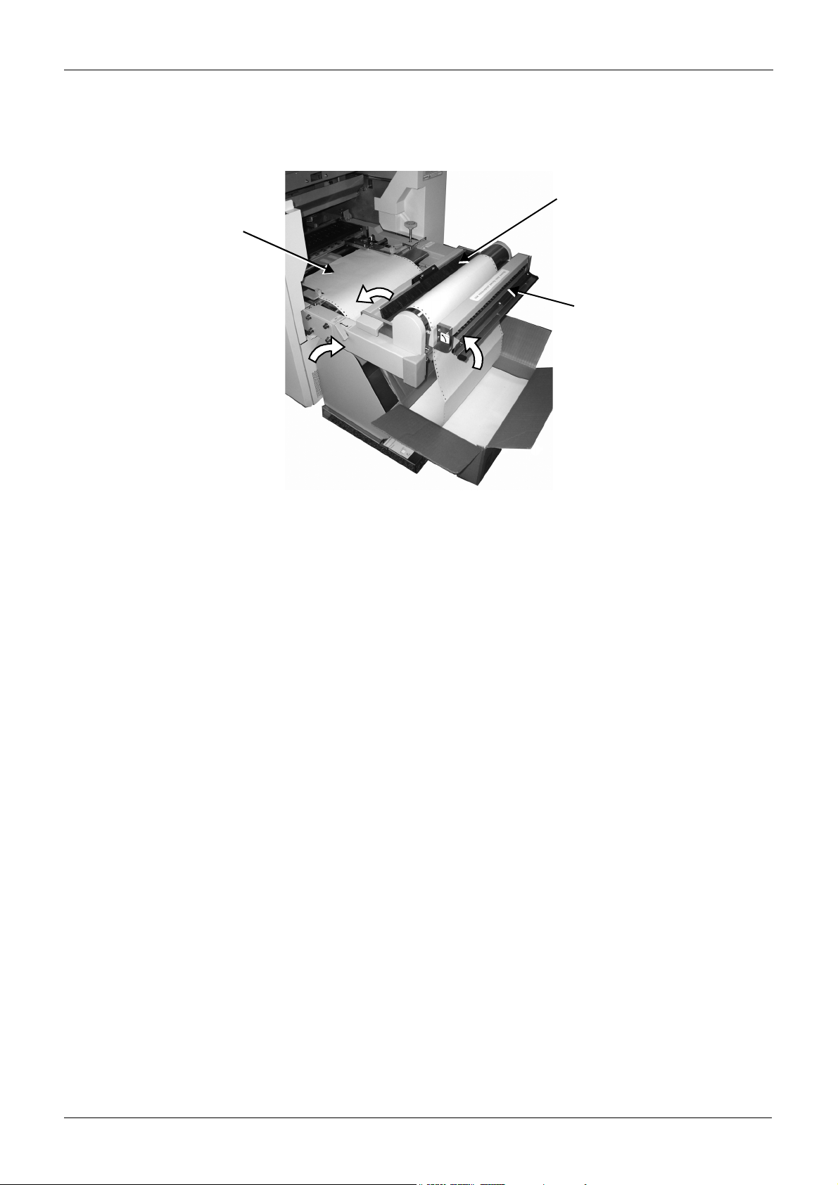
PAPER PATH PAPER LOADING
6. Check that the sprocket holes of the paper are correctly inserted
onto the front tractor pins, then close the tractor covers.
7. Check that the brush is down.
Brush
Paper
Decurler
8. Check that the decurler is released (on the Standard label side).
9. Check that the supplementary table lever is towards the Printing side
and the table is down.
Note: The decurler is provided for the following special situations:
a. If the paper is folded too strongly at the perforations in order to
prevent blurred printing at the perforations.
b. To prevent several sheets from being lifted together.
c. When using normal paper, release the decurler as it may
impede the paper feed.
10. Set the paper length. Press the Long button to increment the units or
the Short button to decrement the units. Press the One Decimal
button to increment the decimal place by 1/6 inch for each press.
Xerox 495 Continuous Feed Duplex Printer Operator Guide Page 5-7
Page 86

PAPER LOADING PAPER PATH
The display shows the folding length in inches and the perforation
number will be recalculated and displayed.
11. Press the Load switch on the autoload panel.
The paper is automatically fed to the stacker through the transfer unit
and fuser to complete the initial setup. If the paper jams during
loading, press the Cancel switch on the autoload panel to stop
autoloading, clear the paper jam then try again (see "Clearing paper
jams" on page 9-3.)
Page 5-8 Xerox 495 Continuous Feed Duplex Printer Operator Guide
Page 87

PAPER PATH SETTING THE PERFORATION POSITION
Setting the perforation position
After a paper jam has been removed or if the paper position is changed
with the Forward or Reverse switch, you will need to set the perforation
position.
Note: This operation is not necessary at ordinary autoloading or during
automatic switching mode (e.g. changing from simplex to duplex). The
paper moves automatically to the correct position before starting to print.
To set the paper position:
1. Check the Perforation Number on the autoload panel.
2. Press Forward/Reverse on the autoload panel, to correct the paper
alignment.
Tractor Cover
Scale
Perforation
3. Press the Fold-out/in switch so that the fold-out/in status of the
perforation at Perforation Number matches the Fold-out/in lamp
status.
Notes:
a. Even when the fold-out/in status of the perforation matches the
Fold-out/in lamp status in, press the Fold-out/in Select switch.
b. The Perforation Number changes with the paper length but is
not equal to the paper length value (inch). Be sure to check the
Perforation Number when setting the perforation position.
The Perforation Number may change with the printing mode
even when the paper length is the same.
c. If your paper is long and the perforation number becomes 13 or
more, be sure to use the supplementary table.
Xerox 495 Continuous Feed Duplex Printer Operator Guide Page 5-9
Page 88

SETTING THE PERFORATION POSITION PAPER PATH
4. Set the supplementary table lever to the Align Perforation side.
Supplementary table
Supplementary table
lever
5. Move the perforation position according to the scale on the
supplementary table.
Supplementary table
lever
Scale
6. Press the Fold-out/in Select switch and set the lever to the Print side
to lower the supplementary table.
Page 5-10 Xerox 495 Continuous Feed Duplex Printer Operator Guide
Page 89

PAPER PATH CUTTING PAPER
Cutting paper
If it is necessary to cut the paper, cut it outside the decurler.
Decurler
Hopper
Paper Cutting Position
Xerox 495 Continuous Feed Duplex Printer Operator Guide Page 5-11
Page 90
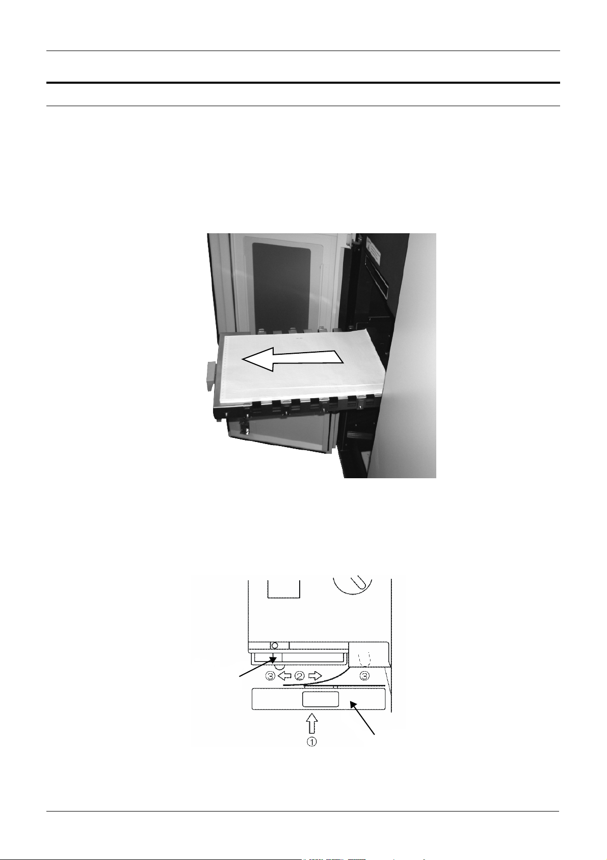
REMOVING PAPER PAPER PATH
Removing Paper
1. To completely remove the paper, cut it at the hopper (see "Cutting
paper" on page 5-11).
2. Press the Eject button located on the touch screen action bar.
3. Press the Stacker Down button on the stacker control panel.
The table stops at the paper removal position.
4. Pull down and fold the paper.
5. Pull the stacker table out using the handles.
6. Remove the paper from the table, push the table back into the
original position, and place the remaining paper along the right side
of the stacker table.
7. Set the table switch to Auto.
8. Adjust the paper forming on the stacker table so that the table will
reach high enough.
Guide
Table
Page 5-12 Xerox 495 Continuous Feed Duplex Printer Operator Guide
Page 91

PAPER PATH REMOVING PAPER
When the stacker table goes up (1), the paper may move to the right
or left (2) and hit the guides (3). This is not good and the printer will
fall into the error “Form length guide held up.” To correct the error,
the paper on the stacker table must be readjusted.
9. Press the Stacker Down button on the stacker control panel.
10. Adjust the paper by pressing it against the right side of the stacker.
11. Set the table switch to Auto.
12. Cloose the right stacker door.
13. Press RESET on the touch screen and then set the printer to ready.
Xerox 495 Continuous Feed Duplex Printer Operator Guide Page 5-13
Page 92

CHECKING PRINTING PAPER PATH
Checking printing
The printer is capable of checking both the front-side and back-side print
quality and position (see "Front and back marking units" on page 2-2).
These can be monitored by:
• Checking the printed paper
• Checking at the printing check position
• Using the printing position check function
Checking printed paper
1. Stop printing after several pages and press the Eject button on the
touch screen to eject the prints in the stacker.
2. Take the prints out of the stacker table and check the print quality
and position.
Checking at the printing check position
Check the printing status at the printing check position in the printer.
Fuser Exit Guide
Back side printing check mirror
1. Print several pages and open the fuser left door (see "Components
inside the Fuser Door" on page 2-6).
2. Open the fuser exit guide and check the front-side printing status
(see "Front and back marking units" on page 2-2).
3. Check the back-side print quality and position using the back-side
printing check mirror.
4. Close the doors and restart printing.
Note: If printing is started immediately after autoloading, several
sheets should be printed until the first sheet is in position. The
number of sheets depends on the print page length.
Page 5-14 Xerox 495 Continuous Feed Duplex Printer Operator Guide
Page 93

PAPER PATH CHECKING PRINTING
Check by the printing position check function
Feed prints from the printer into the stacker table and check the printing
status. After checking, return the paper to the original printing position
and restart printing from the page after the last confirmed print.
1. Print a necessary number of sheets for checking.
2. Open the bubble menu for the printer device and press the Start Print
Position Check command. Paper is forwarded to the stacker and the
stacker automatically lowers.
3. Check the printing status on the stacker table.
4. Press the stacker AUTO button to raise the stacker table.
5. Press RESET to set the printer to Not Ready.
6. Open the bubble menu for the printer device and press the Stop Print
Position Check command. The paper reverses to its original printing
position.
7. Press START to set the printer to Ready.
8. Resume printing.
Note: Before feeding the paper back, check that it is in the original
position on the stacker table. If the paper deviates, the paper may
tear or cause other problems. Make sure that the paper edge is
aligned with the “Align paper here” line.
Xerox 495 Continuous Feed Duplex Printer Operator Guide Page 5-15
Page 94

LOADING PAPER TO A POST-PROCESSING DEVICE PAPER PATH
Loading paper to a post-processing device
To load paper to a post-processing device:
1. Turn the paper output selector lever in the stacker to the
External position.
Paper output
selector lever
2. Press Load in the bubble menu to release enough paper for the postprocessing device.
Note: If insufficient paper is ejected, then the distance between
devices has not been properly set during the definition of the print
line.
Page 5-16 Xerox 495 Continuous Feed Duplex Printer Operator Guide
Page 95

6. Adjusting print quality
These settings should be made during the definition of a job and recalled
when the job is run (see "Defining applications" on page 7-12).
The setting for the individual marking units can be made locally using the
Notebook settings, if they are made available to you. These changes are
made by selecting one of the five possible settings defined for the job
(see "Notebook offsets" on page 4-7).
Print density affects toner consumption and fusing. The best contrast
depends on the paper used and for each paper there is a setting above
which the contrast remains at the maximum, while the fusing quality
diminishes and consumption increases.
Note: Print quality is also affected by the paper thickness (see "Defining
paper characteristics" on page 7-7).
Xerox 495 Continuous Feed Duplex Printer Operator Guide Page 6-1
Page 96

ADJUSTING PRINT QUALITY
Page 6-2 Xerox 495 Continuous Feed Duplex Printer Operator Guide
Page 97

7. Defining production jobs
This chapter contains the procedures for creating jobs. All of the screens
are accessed under the Definitions tab, the facilities of which are
available to the Key Operator level User and above.
To create a new job, the paper to be used must be defined and must be
available. The printing application must have been created at a system
level in order to be able to carry out tests.
Once a job has been created, you will normally only have to recall the job
and load the correct paper to be able to print it. For duplex jobs, check
that the attachment to be used is available in the print line segment
selected.
Xerox 495 Continuous Feed Duplex Printer Operator Guide Page 7-1
Page 98

QUICK START DEFINING PRODUCTION JOBS
Quick start
There are seven steps for creating a job:
Step Actions
Checking the existence of a
job
Defining a new job 1. Select the Job tab, create a new job and choose the name of the paper and
1. Select the Job tab and press the press to use the search facility.
application that you have just created (or others since several jobs can use the
same paper, for example).
2. Press the diskette icon, then select the Write As field.
3. Type in the name of the job, then press Enter and then the OK button to save
it. If a job with the same name and same characteristics already exists, you will
receive a message asking if you want to replace the existing definition.
Defining a new paper type
(if necessary)
Defining a new application
type
(if required)
Defining a new line
(if required)
Defining a new attachment
(if required)
1. Select the Paper tab, create a new paper type and define the characteristics
of the new paper (format and thickness).
2. Press the diskette icon, then select the Write As field.
3. Type in the name of the paper, then press Enter and then the OK button to
save it. If paper with the same name and same characteristics already exists,
you will receive a message asking if you want to replace the existing definition.
1. Select the Application tab, press the new application button and define the
characteristics for the new application (emulation, resolution, etc.).
2. Press the diskette icon, then select the Write As field.
3. Type in the name of the application, then press Enter and then the OK button
to save it. If an application with the same name and same characteristics
already exists, you will receive a message asking if you want to replace the
existing definition.
1. Select the Line tab and define the paper path for the new line.
2. Press the diskette icon, then select the Write As field.
3. Type in the name of the print line and then press Enter and then the OK button to save it. If a print line configuration with the same name and same characteristics already exists, you will receive a message asking if you want to replace
the existing definition.
1. Select the Attachment tab, create a new attachment and define the characteristics of the new attachment (emulation should be the same as that created
in the Application screen, choice between channel and TCP/IP).
2. Press the diskette icon, then select the Write As field.
3. Type in the name of the attachment, then press Enter and then the OK button to save. If an attachment with the same name and same characteristics
already exists, you will receive a message asking if you want to replace the
existing definition.
Testing the new job 1. Select the job to test from the Production tab.
2. Select the connection and put it online.
3. Start the printer.
Page 7-2 Xerox 495 Continuous Feed Duplex Printer Operator Guide
Page 99

DEFINING PRODUCTION JOBS CHECKING THE EXISTENCE OF A JOB
Checking the existence of a job
1. Select the Definitions tab, then the Job tab.
2. Press the icon on the top left of the Job pull-down list to display
the search facility. The scroll down list on the right shows all of the
entries from which you can choose a Job selection.
3. Use the keyboard to enter all or part of the Job name. The Job name
will be highlighted as soon as sufficient information is entered.
4. Press the Enter button to select the highlighted Job and return to the
Job tab.
5. Otherwise, press the Esc button to return to the Job tab without
making a selection.
Xerox 495 Continuous Feed Duplex Printer Operator Guide Page 7-3
Page 100

DEFINING A JOB DEFINING PRODUCTION JOBS
Defining a job
Before you can create a job, you will need to define:
• The paper See “Defining paper characteristics” on page 7..
• The application See “Defining applications” on page 12..
Note: To define a job you must have the User status of Key
Operator or higher.
A job definition determines the previously defined characteristics for the
paper and application that will be used to run a job.
The Default job configuration is as follows:
• Paper pull-down list - Default
• Application pull-down list - Default
Refer to the appropriate sections for the default values of these items.
Creating or amending a job
This procedure assumes that the Paper and Application definitions have
already been made. If you are starting a new job with new resources,
these items need to be created first.
Note: The original settings are those saved for the job; they are not the
same as the default settings. An asterisk (*) is displayed to the right of
the Job pull-down list for any modification made to these settings.
To create or amend a job:
1. Select the Definitions tab, then the Job tab.
The Job screen groups the Paper and Application screen settings
associated with a normal job.
Page 7-4 Xerox 495 Continuous Feed Duplex Printer Operator Guide
 Loading...