

Page 1

;HUR['RFX3ULQW,36
,QVWDOODWLRQ3ODQQLQJ*XLGH
9HUVLRQ
$XJXVW
3
Page 2

;HUR[&RUSRUDWLRQ
6RXWK$YLDWLRQ%RXOHYDUG
(O6HJXQGR&$
¸
E\;HUR[&RUSRUDWLRQ$OOULJKWVUHVHUYHG
&RS\ULJKWSURWHFWLRQFODLPHGLQFOXGHVDOOIRUPVDQGPDWWHUVRI
FRS\ULJKWDEOHPDWHULDODQGLQIRUPDWLRQQRZDOORZHGE\VWDWXWRU\RU
MXGLFLDOODZRUKHUHLQDIWHUJUDQWHGLQFOXGLQJZLWKRXWOLPLWDWLRQ
PDWHULDOJHQHUDWHGIURPWKHVRIWZDUHSURJUDPVZKLFKDUHGLVSOD\HG
RQWKHVFUHHQVXFKDVLFRQVVFUHHQGLVSOD\VORRNVHWF
3ULQWHGLQWKH8QLWHG6WDWHVRI$PHULFD
3XEOLFDWLRQQXPEHU3
;HUR[·,7KH'RFXPHQW&RPSDQ\WKHVW\OL]HG;DQGDOO;HUR[
SURGXFWQDPHVPHQWLRQHGLQWKLVSXEOLFDWLRQDUHWUDGHPDUNVRI;HUR[
&RUSRUDWLRQ3URGXFWVDQGWUDGHPDUNVRIRWKHUFRPSDQLHVDUHDOVR
DFNQRZOHGJHG
&KDQJHVDUHSHULRGLFDOO\PDGHWRWKLVGRFXPHQW&KDQJHVWHFKQLFDO
LQDFFXUDFLHVDQGW\SRJUDSKLFHUURUVZLOOEHFRUUHFWHGLQVXEVHTXHQW
HGLWLRQV
Page 3
Laser safety
Warning: Adjustments, use of controls, or performance of
!
procedures other than those specified herein may result in
hazardous light exposure.
The Xerox DocuPrint printers are certified to comply with the
performance standards of the U.S. Department of Health, Education,
and Welfare for Class 1 laser products. Class 1 laser products do not
emit hazardous radiation. The DocuPrint printers do not emit
hazardous radiation because the laser beam is completely enclosed
during all modes of customer operation.
The laser danger labels on the system are for Xerox service
representatives and are on or near panels or shields that must be
removed with a tool. DO NOT REMOVE LABELED PANELS OR
PANELS NEAR LABELS. ONLY XEROX SERVICE
REPRESENTATIVES HAVE ACCESS TO THESE PANELS.
Ozone information
Operation safety
This product produces ozone during normal operation. The amount
of ozone produced depends on copy volume. Ozone is heavier than
air. The environmental parameters specified in the Xerox installation
instructions ensure that concentration levels are within safe limits. If
you need additional information concerning ozone, call 1-800-8286571 to request the Xerox publication 600P83222, OZONE.
Your Xerox equipment and supplies have been designed and tested
to meet strict safety requirements. They have been approved by
safety agencies, and they comply with environmental standards.
Please observe the following precautions to ensure your continued
safety.
• Always connect equipment to a properly grounded electrical
outlet. If in doubt, have the outlet checked by a qualified
electrician.
Warning: Improper connection of the equipment grounding
!
conductor may result in risk of electrical shock.
• Never use a ground adapter plug to connect equipment to an
electrical outlet that lacks a ground connection terminal.
• Always place equipment on a solid support surface with
adequate strength for its weight.
XEROX DOCUPRINT 4850/4890 IPS INSTALLATION PLANNING GUIDE iii
Page 4

• Always use materials and supplies specifically designed for
your Xerox equipment. Use of unsuitable materials may result in
poor performance and may create a hazardous situation.
• Never move either the printer or the Printer Controller without
first contacting Xerox, Xerox Ltd., or Fuji Xerox for approval.
• Never attempt any maintenance that is not specifically
described in this documentation.
• Never remove any covers or guards that are fastened with
screws. There are no operator-serviceable areas within these
covers.
• Never override electrical or mechanical interlocks.
• Never use supplies or cleaning materials for other than their
intended purposes. Keep all materials out of the reach of
children.
• Never operate the equipment if you notice unusual noises or
odors. Disconnect the power cord from the electrical outlet and
call service to correct the problem.
If you need any additional safety information concerning the
equipment or materials Xerox supplies, call Xerox Product Safety at
the following toll-free number in the United States:
1-800-828-6571
For customers outside the United States, contact your local Xerox
representative or operating company.
iv XEROX DOCUPRINT 4850/4890 IPS INSTALLATION PLANNING GUIDE
Page 5

Table of Contents
Laser safety iii
Ozone information iii
Operation safety iii
Introduction ix
About this guide ix
Contents ix
Conventions x
Notice x
1. Product overview 1-1
System overview 1-1
4850/4890 IPS hardware features 1-3
NPS/IPS Dual Mode 1-5
Sixth Sense 1-5
Base system components 1-6
2. Controller components and options 2-1
Controller hardware 2-1
Sun Ultra 2 workstation 2-1
Sun Ultra 60 workstation 2-4
IPS user interface screen 2-9
Host Channel Unit (HCU)—channel-attached systems only 2-10
3. Printer components and options 3-1
Printer components 3-1
Printer control console 3-3
Printer options 3-4
High-capacity feeder 3-4
Dual stacker 3-5
Stitcher/stacker 3-6
Customer-changeable unit (CCU) 3-7
Bypass transport option (4890 only) 3-8
Interface with third-party devices 3-9
Electrical interface 3-9
XEROX DOCUPRINT 4850/4890 IPS INSTALLATION PLANNING GUIDE v
Page 6

TABLE OF CONTENTS
4. Preparing for installation 4-1
Responsibilities 4-1
Xerox responsibilities 4-1
Customer responsibilities 4-2
Installation planning checklist 4-4
Connectivity requirements 4-7
Ethernet specifications 4-7
Token Ring specifications 4-7
5. Controller specifications and requirements 5-1
Power requirements 5-1
Outlet configurations 5-2
Environmental specifications 5-3
Space requirements 5-4
Printer controller placement 5-4
Controller hardware specifications and requirements summary 5-9
6. Printer specifications and requirements 6-1
Power requirements 6-1
Outlet configurations 6-2
Printer outlet voltages—60 Hz 6-2
Printer outlet voltages—50 Hz 6-3
Environmental specifications 6-4
Space requirements 6-5
Printer placement 6-5
CCU changeout cart 6-10
Space planning guidelines 6-11
Clearance space requirements 6-11
Shared space 6-11
Floor leveling 6-15
Delivery access requirements 6-15
Printer hardware specifications and requirements summary 6-18
Space planning templates 6-20
7. System connections 7-1
Cable lengths 7-1
Cable locations 7-2
Channel attachments 7-2
8. Installation 8-1
Installation process 8-1
Your responsibilities 8-2
Defining the IPS printer to the host 8-3
vi XEROX DOCUPRINT 4850/4890 IPS INSTALLATION PLANNING GUIDE
Page 7

TABLE OF CONTENTS
Software licensing 8-3
Ongoing maintenance 8-4
Routine maintenance 8-4
Meter reading and reporting 8-4
A. Supplies A-1
Paper and other throughput stocks A-1
Selecting paper A-1
Paper care A-3
Other supplies A-6
Dry ink A-6
Fuser lubricant A-6
Developer A-6
Stitcher wire A-7
Diskettes A-7
Cartridge tapes A-7
Fonts A-7
Consumable supplies tables A-8
Paper and special stocks tables A-8
Complete supplies list—4850/4890 printers A-11
Ordering supplies A-13
B. Xerox support services B-1
Xerox Customer Service Support Center B-1
Xerox Printing Systems Customer Support Center B-2
Xerox Customer Documentation Catalog B-3
Xerox Documentation and Software Services (XDSS) B-3
Operator training B-3
Xerox Customer Education B-4
Xerox Font Center B-4
C. Related publications C-1
D. Defining the channel-attached printer to the host D-1
MVS parameters D-1
OS/2 procedures D-4
AIX procedures D-5
VM sample definitions D-6
VSE sample definitions D-6
E. Defining the printer to the host: TCP/IP attachment E-1
MVS or OS/390 parameters E-1
Software prerequisites – MVS E-1
XEROX DOCUPRINT 4850/4890 IPS INSTALLATION PLANNING GUIDE vii
Page 8

TABLE OF CONTENTS
Network configurations – MVS E-1
Configuration steps – MVS E-2
1. Configure the IPS printer for TCP/IP at the GUI E-2
2. Configure the MVS CCU for the MVS host to MVS E-2
3. Configure the PSF printer in JES2 or JES3 E-2
4. Configure the printer in PSF/MVS E-7
5. Configure TCP/IP for MVS for the printer E-11
6. Test the printer to ensure it prints from the MVS host E-14
Correcting for printer performance issues – MVS E-16
References E-17
AS/400 parameters E-18
Software prerequisites – AS/400 E-18
Network configurations – AS/400 E-18
Configuration steps – AS/400 E-19
1. Configure the IPS printer for TCP/IP at the GUI E-19
2. Create the PSF/400 configuration E-19
3. Create the printer device description – AS/400 E-20
4. Test the printer connection – AS/400 E-22
Correcting for printer performance issues – AS/400 E-24
References – AS/400 E-24
AIX parameters E-25
Software prerequisites – AIX E-25
Network configurations – AIX E-26
Configuration steps—AIX E-26
References E-27
OS/2 parameters E-28
Software prerequisites – OS/2 E-28
Network configurations – OS/2 E-28
Configuration steps – OS/2 E-29
1. Configure the printer for TCP/IP in OS/2 E-29
2. Provide TCP/IP routing information if necessary E-29
3. Define the printer to PSF/2 E-30
4. Define a PSF/2 print queue for the printer (optional) E-31
5. Test the printer connection in OS/2 E-32
Correcting for printer performance issues – OS/2 E-34
References – OS/2 E-35
Glossary GLOSSARY-1
Index INDEX-1
viii XEROX DOCUPRINT 4850/4890 IPS INSTALLATION PLANNING GUIDE
Page 9

About this guide
Introduction
This Xerox Printing Systems Installation Planning Guide helps you
prepare for delivery and installation of your new Xerox DocuPrint
printing system.
This guide is intended for the person responsible for coordinating the
installation of the DocuPrint printer at your site. It lists the tasks you
must complete before installation can begin, as well as your
responsibilities during the installation.
Before using this guide, become familiar with its contents and
conventions.
Contents
This guide contains the following:
• Chapter 1, "Product overview," provides an overview of the
DocuPrint 4850 and 4890 printing systems.
• Chapter 2, "Controller components and options," describes
system controller hardware, software, and options.
• Chapter 3, "Printer components and options," describes printer
components, configurations, and options.
• Chapter 4, "Preparing for installation," provides a checklist of
tasks that must be accomplished before the installation. It also
explains connectivity requirements for transporting documents
from the host or client to the DocuPrint printing system.
• Chapter 5, "Controller specifications and requirements,"
describes power, environmental, and space requirements for
the system controller.
• Chapter 6, "Printer specifications and requirements," describes
power, environmental, and space requirements for the printer.
Space planning guidelines and diagrams are provided to help
you set up the work area.
• Chapter 7, "System connections," provides cable requirements
for your DocuPrint 4850 and 4890 printing systems.
• Chapter 8, "Installation," describes the activities that occur
during installation. It also describes ongoing maintenance
activities.
• Appendix A, "Supplies," describes how to select, store, and use
supplies for the DocuPrint printing system. It also provides a list
of consumable supplies you can order.
XEROX DOCUPRINT 4850/4890 IPS INSTALLATION PLANNING GUIDE ix
Page 10
INTRODUCTION
Conventions
• Appendix B, "Xerox support services," explains how to utilize
available Xerox support services.
• Appendix C, "Related publications," lists other Xerox
documents that are part of this publication set.
• Appendix D, "Defining the channel-attached printer to the host,"
provides explanations and sample printer parameters for
defining your channel-attached printer to your host.
• Appendix E, "Defining the printer to the host: TCP/IP
attachment," provides instructions, prerequisites, and sample
printer parameters for defining your TCP/IP-attached printer to
your host.
A glossary and index are provided at the back of the guide.
This document uses the following conventions:
Italics—Document and library names are shown in italics (for
example, the Xerox DocuPrint IPS Series Messages Guide).
Notice
Note: Notes are hints that help you perform a task or understand
the text.
Caution: Cautions alert you to an action that could damage
hardware or software.
Warning: Warnings alert you to conditions that may affect the
!
safety of people.
This publication may contain descriptions of concepts and features
not currently available for your Xerox printing system. Consult your
Xerox sales representative or your operating system software
program description for additional information.
x XEROX DOCUPRINT 4850/4890 IPS INSTALLATION PLANNING GUIDE
Page 11

System overview
1. 1Product overview
This chapter provides an overview of the features and functions of
the Xerox DocuPrint 4850 IPS and the 4890 IPS.
The Xerox DocuPrint 4850 IPS and 4890 IPS are cut-sheet, duplex
highlight color printers that are fully compatible with the IBM AFP
architecture. They accept an IPDS data stream from any PSF eligible
platform, including MVS, VM, VSE, OS/2, OS/400 (with TCP/IP only),
and AIX. They are plug-compatible in the AFP/IPDS environment,
and emulate an IBM IPDS Group 3 page printer with the AFIG
(Advanced Function Image and Graphics) option.
The IPS printer series is a combination of proven Xerox print engines
matched with a high-performance RISC-based controller. Each
system consists of a Sun workstation controller and the printer,
sometimes referred to as the Image Output Terminal (IOT).
Host environments The IPS emulates an IBM AFP Group 3 page printer with the
Advanced Function Image and Graphics (AFIG) option and can print
in all the following PSF environments:
• MVS
• VM (channel-attached only)
• VSE (channel-attached only)
• OS/2
• OS/400 (with TCP/IP only)
• AIX
Note: Although PSF/VSE does not support TCP/IP directly, a
printing system with PSF/2, PSF/6000, or InfoPrint Manager can
attach to a PSF/VSE system and the PSF/2, PSF/6000, or InfoPrint
Manager can furnish the TCP/IP support for the IPS printer.
Note: There is no minimum host operating system software level
required to support IPS. The minimum PSF levels needed to support
the IPS are:
• PSF/MVS: V2.1
• PSF/VM: V2.1
• PSF/VSE: V2.2
• PSF/400: V3.2
• PSF/6000: V2.1
• PSF/2: V2.0
XEROX DOCUPRINT 4850/4890 IPS INSTALLATION PLANNING GUIDE 1-1
Page 12
PRODUCT OVERVIEW
1
The DocuPrint IPS can be set up to receive data from the IBM host
in one of two ways:
• Through a bus and tag channel connection.
Note: If your system will be channel-attached, the printer
controller requires an additional component called a Host
Channel Unit (HCU), which interfaces between the IBM host and
the IPS controller.
• Through a Token Ring or Ethernet interface using TCP/IP (the
HCU is not used).
Note: A transmission rate of at least 16 megabits per second
should be used with a Token Ring interface on the IPS. (Overall
performance depends on network traffic and job density.)
• The software supports Token Ring over TCP/IP, and
Ethernet over TCP/IP, with the exception of VM and VSE
platforms.
• Of the other platforms that support TCP/IP, only the
RS/6000 supports 100 Mb Ethernet connectivity.
Note: Customers can have multiple connectivities (Token
Ring, Ethernet, or Bus and Tag), but only one type of
connectivity can be active at any given time.
Data is printed at production speeds:
• 4850 IPS: Up to 50 impressions per minute
• 4890 IPS: Up to 92 impressions per minute.
A full-color graphical user interface on the Sun workstation enables
interaction with the IPS.
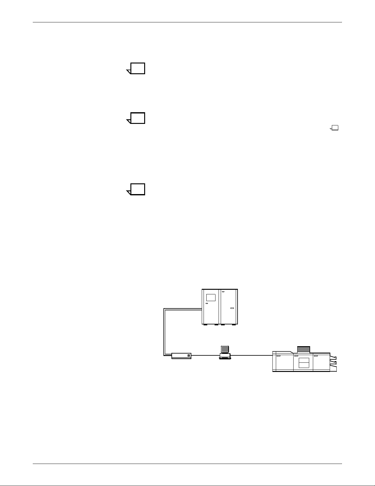
Figure 1-1. Xerox 4850/4890 IPS: channel-attached
configuration
IBM
Host
7
4
6
1 Host system (PC or mainframe)
2 4850 or 4890 IPS printer
3 Printer interface cable (DCIM2)
4 Sun workstation controller
5 SCSI interface
6 Host Channel Unit (HCU)
7 Bus and tag cables
5
3
2
1-2 XEROX DOCUPRINT 4850/4890 IPS INSTALLATION PLANNING GUIDE
Page 13

4850/4890 IPS hardware features
PRODUCT OVERVIEW
Figure 1-2. 4850/4890 IPS: TCP/IP configuration
1 Host system (PC or mainframe)
2 Token Ring or Ethernet network connection
3 Sun workstation controller
4 Printer interface cable (DCIM2)
5 4850 or 4890 IPS printer
For information on the various IPS printer configuration options, refer
to the “Printer components and options” chapter of this guide.
The 4850/4890 IPS systems provide numerous features that can be
accessed with standard AFP compatible software products. The
following features are available and can be enabled or configured
using the graphical user interface on the printer controller:
• Highlight color — The 4850 and 4890 IPS have the capability
of printing in one highlight color plus black. A number of inks are
available for adding color to documents: red, green, blue, cyan,
magenta, brown, cardinal, royal, ruby, and violet.
When a colored ink is installed in the IPS, you can combine
black and the additional color under software control to:
— Create darker shades by mixing black and a color
— Create lighter tints by letting the white of the paper show
through between the black or colored dots.
• Up to four input trays — Two addressable input trays are
standard with the printing system. Two additional feeder trays
are available as options. These trays can be used to configure
print jobs in the most effective manner. For example, the trays
can be used to provide nonstop printing of a complex job that
requires multiple paper stocks, or only a few paper stocks, but
using the continuous loading capability of the input trays. A
different tray can also be selected for each copy of a specific
page in a print job; for example, to provide different paper colors
for specific pages.
Feeder tray capacities, based on 20-pound or 80 gsm (grams
per square meter) bond, are:
— Tray 1: 1000 sheets
— Tray 2: 500 sheets
— High-capacity feeder trays (3 and 4): 1000 sheets each.
• Advanced paper handling — The IPS can handle paper
stocks ranging in size from 8 by 10 inches / 203 by 254 mm to
8.5 by 14 inches / 216 by 356 mm, including A4, and in weight
from 20-pound or 80 gsm bond to 110-pound / 200 gsm index.
XEROX DOCUPRINT 4850/4890 IPS INSTALLATION PLANNING GUIDE 1-3
Page 14

PRODUCT OVERVIEW
Jobs can also be printed on special stocks such as labels and
transparencies.
The printer engine monitors the print job so that, should a paper
jam occur, the job resumes on the correct page, providing
complete document integrity.
• 300 dpi resolution — The 4850 and 4890 IPS provide high
print quality at 300 dpi resolution. They can receive data at 240
or 300 dpi; 240 data is converted to 300 by the controller.
The IPS must be configured to the same font resolution as the
host input data stream (refer to your 4850/4890 IPS Guide to
Configuring and Managing the System for instructions on
configuring for the correct input resolution). Conflicts between
the input font resolution and the IPS configuration could result
in inability to print the job, or in variable data missing from the
output.
Note: You will normally achieve better print quality by
converting all 240 dpi fonts and other resources to 300 dpi
before printing, rather than leaving the conversion for the
controller to do. However, you should always run test prints to
validate your particular applications.
• Bypass transport option (4890 IPS only) — The bypass
transport enables sheets to pass through the printer output
module to a third-party finishing device. With such a device, you
add to your 4890 IPS such finishing capabilities as saddlestitching, binding, trimming, etc. The bypass transport fits into
tray 1 of the dual stacker, and can be easily removed and
installed by the operator. (For further information on this option,
refer to the “Bypass transport specifications” appendix of this
guide.)
• Sixth Sense Remote Service — The Xerox Sixth Sense
Remote Service feature allows Xerox support personnel to
access IPS/NPS controller via modem from a remote location.
More information about Remote Service can be found in the
Xerox DocuPrint 4850/4890 IPS Troubleshooting Guide.
• Choice of dual or stitcher stacker — Your 4850/4890 IPS is
available with one of two stacker types: a dual stacker, with two
output trays, or a stitcher/stacker which can place a wire stitch
in sets of up to 50 sheets.
Output tray capacities, based on 20-pound or 80 gsm stock,
are:
— Dual stacker trays 1 and 2: 750 sheets each
— Stitcher/stacker: 2000 sheets.
1-4 XEROX DOCUPRINT 4850/4890 IPS INSTALLATION PLANNING GUIDE
Page 15

NPS/IPS Dual Mode
PRODUCT OVERVIEW
The Xerox DocuPrint Dual Mode option enables both DocuPrint IPS
and NPS systems to coexist on the same printer controller (Sun
workstation). This allows the DocuPrint system to receive data
streams supported by NPS and IPS, including IPDS, PostScript
Levels 1 and 2, HP PCL5c, HP PCL5e, and ASCII.
Either of the following two types of configurations may be used:
• The same Token Ring or Ethernet connection can be used for
both IPDS (IPS) and Postscript/PCL (NPS).
• Both a Token Ring card and an Ethernet card can reside in the
Sun workstation controller, with one being used for IPDS and
the other for PostScript/PCL.
The customer may switch from one mode to the other. When your
system is operating in IPS mode, it can accept PostScript and PCL
data streams in the background; however, you can print these jobs
only when the system is in NPS mode. When in NPS mode, the
system cannot accept IPDS data streams in the background; you can
print them only when the system is in IPS mode.
Refer to the Xerox DocuPrint IPS/NPS Dual Mode Switching
Instructions and other Xerox DocuPrint IPS documentation for more
information.
Sixth Sense
Sixth Sense is a unique suite of diagnostic tools that allows Xerox
customer service engineers, analysts, and consultants to serve
customers more effectively.
Sixth Sense is intended to automate and expedite the range of
service-related support functions. Sixth Sense is a tool that enables
Xerox to provide benchmark service support. Xerox customers
benefit from the ability to bring broader support to focus more quickly.
For example, Sixth Sense can allow the Service Representative to
repeatedly "preview" the condition of the system prior to an actual
site visit. This may provide the ability to determine the correct part or
piece of information to have on hand when the site visit is made.
Sixth Sense is a no charge feature available to customers through
Xerox Service. The customer need only provide an analog phone line
for use by the Sixth Sense modem connection. For those customers
unable to dedicate a phone line to the Sixth Sense connection, three
and five port phone share devices are available for purchase.
To take advantage of Sixth Sense, the customer needs to:
• Request Sixth Sense enablement through Xerox Service
• Provide an analog phone line
• If necessary, purchase an optional phone share device.
More information about the Sixth Sense can be found in the Xerox
DocuPrint 4850/4890 NPSIPS System Administration Guide.
XEROX DOCUPRINT 4850/4890 IPS INSTALLATION PLANNING GUIDE 1-5
Page 16

PRODUCT OVERVIEW
Base system components
The IPS system consists of the following major components:
• Printer controller — The printer controller (also called the
system controller) accepts IPDS data from the host, processes
the data, and sends the data to the printer engine using the IPS
operating system. The controller provides the printer with print
data and commands, and receives status information from the
printer.
• Printer — The printer, also called the Image Output Terminal
(IOT), accepts formatted pages of data from the printer
controller and performs the imaging and printing of documents.
The printer also provides paper stacking, collating, and optional
finishing capabilities you enable using the IPS application
software accessed through the graphical user interface.
1-6 XEROX DOCUPRINT 4850/4890 IPS INSTALLATION PLANNING GUIDE
Page 17

Controller hardware
2. 2Controller components and
options
The printer controller provides the printer with print data and
commands, and receives status information from the printer. This
chapter describes the components and options available for the
controller.
The printer controller consists of a Sun workstation and, if you are
printing data received over a channel, a Host Channel Unit (HCU).
The controller uses proprietary Xerox hardware, firmware, and
software to run the IPS.
Your controller may be either a Sun Ultra 2 or Ultra 60 workstation.
The following sections contain information about both the Ultra 2 and
the Ultra 60.
Sun Ultra 2 workstation
The Sun workstation provides a user interface to the print engine. It
is used to operate the IPS software which controls the printer. The
workstation contains the following hardware components:
• Sun Ultra 2 workstation processor (system unit)
• Display monitor
• Keyboard and mouse
• Connectivity boards for Ethernet and, optionally, Token Ring
• A Data Control Interface Module (DCIM2) card installed in the
processor to interface with the print engine.
XEROX DOCUPRINT 4850/4890 IPS INSTALLATION PLANNING GUIDE 2-1
Page 18
CONTROLLER COMPONENTS AND OPTIONS
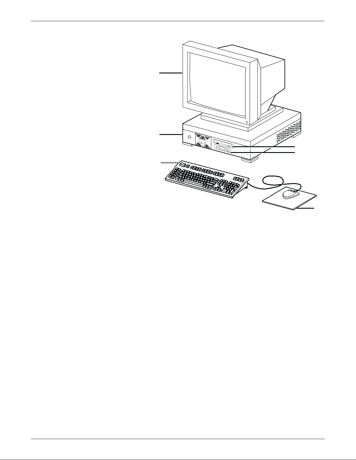
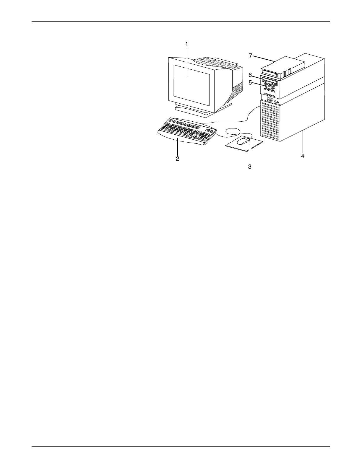
Figure 2-1. Components of the Sun Ultra 2 workstation
2
1
6
5
4
3
1 Processor
2 Monitor
3 Mouse and mouse pad
4 Keyboard
5 Diskette drive
6 CD-ROM drive
Processor The processor is the central processing unit of the Sun workstation.
It contains a power switch, an internal disk drive, a diskette drive, a
CD-ROM drive, a power receptacle and outlet, connectors and ports.
The processor has the following components:
• Internal disk drive: One high-speed internal disk drive is
provided as a standard feature of the processor. The operating
system, the IPS application, and any queued print jobs are
stored on the internal disk. This disk cannot be used to store
other applications or data except as directed by your service
representative.
• Diskette drive: Diskettes inserted into a diskette drive are used
to load files to, and back up files from, the internal disk drive.
The diskette drive uses industry standard 3.5 inch, 1.44 Mb,
double-sided, high-density diskettes. This diskette drive is not
an input source for print jobs nor any other data or application; it
is reserved exclusively for use by a service representative to
update software and to store files. The diskette drive is located
in the processor, on the right front section for the Ultra 2.
2-2 XEROX DOCUPRINT 4850/4890 IPS INSTALLATION PLANNING GUIDE
Page 19
CONTROLLER COMPONENTS AND OPTIONS
• CD-ROM drive: The CD-ROM drive is a high density, read-only,
optical laser storage device used for loading the IPS operating
system and other files. The CD-ROM drive is located in the
processor above the floppy drive.
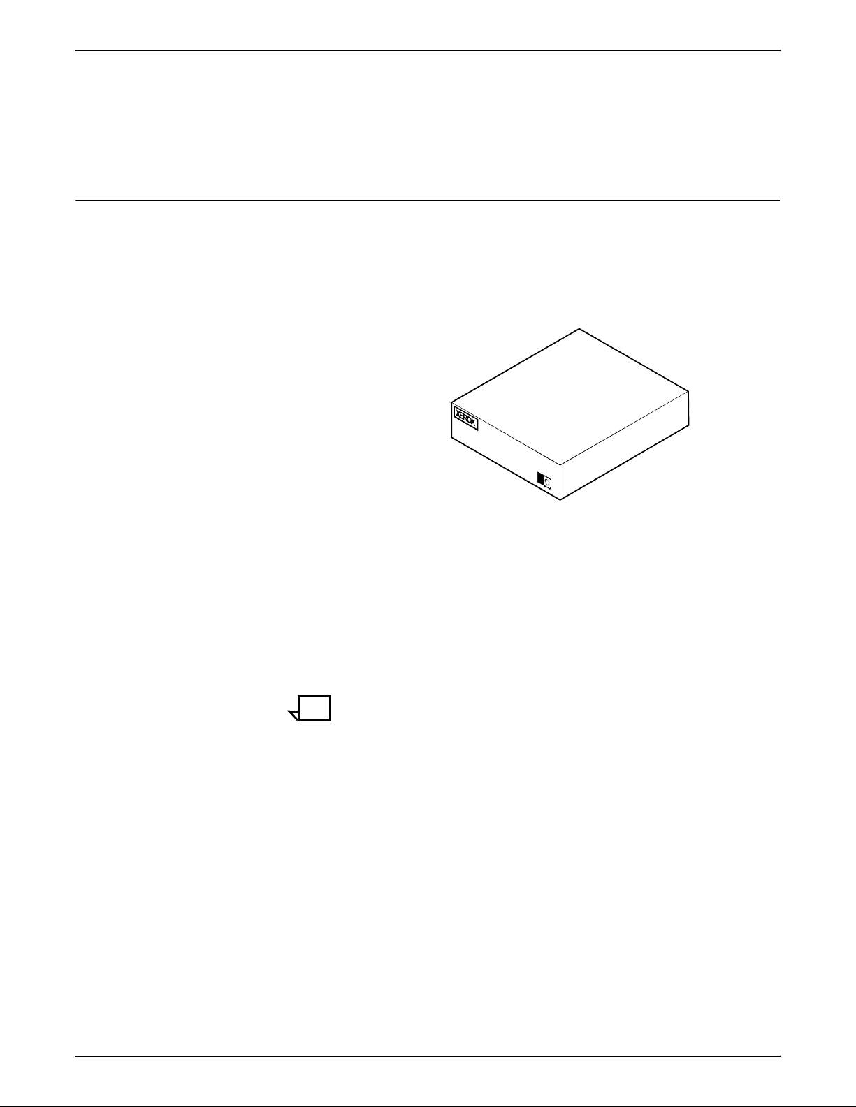
• Cartridge tape drive (not shown): An optional 8 GB, 4 mm
SCSI cartridge tape drive also is available for the IPS. Like the
diskette and CD drives, this tape drive is not an input source for
print jobs or for any other data or application. It provides the
service representative with another means of loading system
maintenance files or saving diagnostic information.
Caution: When installing a cartridge drive on an IPS with a
host channel unit (HCU), the tape drive must be “daisy-chained”
to the HCU. In this situation, do not attempt to run both the tape
drive and the HCU at the same time.
• Back panel: The back panel of the processor has a power
switch, a power receptacle and outlet, connectors, connector
openings, and ports. The following figure shows the back panel
of the Sun workstation that is part of your IPS controller.
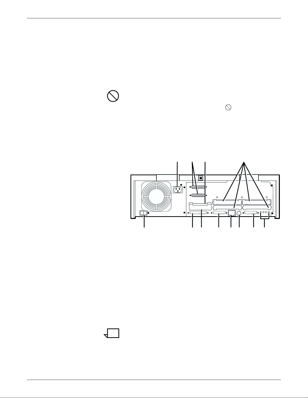
Figure 2-2. Back panel of the Sun Ultra 2 processor
11
3
2
3
2
10
9
4
1
0
8
7
5
6
1
12
1 Power inlet
2 Serial connectors (2): RS-432/RS-232
3 Graphics/video output: UPA slot
4 Sbus slots (Number of slots varies depending on the model)
5 Audio connectors (4)
6 Parallel connector
7 Keyboard/mouse connector
8 TPE connector
9 MII connector
10 UPA slot
11 SCSI connector
12 Power on/Standby switch
Note: The controller back panel contains two serial ports on
one DB-25 connector. Both ports are used exclusively by the
IPS software for diagnostic purposes. The ports and diagnostic
software are accessed only by the service representative.
XEROX DOCUPRINT 4850/4890 IPS INSTALLATION PLANNING GUIDE 2-3
Page 20

CONTROLLER COMPONENTS AND OPTIONS
Display monitor The display monitor has a 1192 x 700 pixel screen which displays the
Keyboard The keyboard consists of alphanumeric keys similar to a typewriter,
Mouse The mouse is another main method of communicating with the
IPS graphical user interface windows.
symbols and special character keys, an extended character set, and
function keys. The keyboard is one of your main methods of
communicating with the printer. You can use the keyboard to make
selections, and to enter commands that control functions such as
requesting sample prints, obtaining billing meter totals, shutting down
the system, and so forth.
printer. The mouse has three buttons. The left and right buttons are
used to select IPS functions. The center button provides additional
functions that you will not be required to use. If your workstation has
an optical mouse, it must remain on its designated metallic pad to be
active. If the mouse has a roller ball instead of an optical sensor
underneath, it requires a non-metallic pad.
Note: Printer controller hardware configurations are subject to
upgrade.
Sun Ultra 60 workstation
The Sun Ultra 60 workstation provides a user interface to the print
engine. It has a high performance RISC processor chipset, based on
the industry standard Scalable Processor Architecture (SPARC). It is
used to operate the software that controls the printer. The
workstation contains the following hardware components:
• Sun Ultra 60 workstation processor (system unit)
• Display monitor
• Keyboard and mouse
• Diskette, CD-ROM, and cartridge tape drives
• Connectivity board for Ethernet and, optionally, Token Ring
• A Data Control Interface Module (PDCIMu) card installed in the
processor to interface with the print engine.
2-4 XEROX DOCUPRINT 4850/4890 IPS INSTALLATION PLANNING GUIDE
Page 21
CONTROLLER COMPONENTS AND OPTIONS
Figure 2-3. Components of the Sun Ultra 60 workstation
1 Monitor
2 Keyboard
3 Mouse
4 Processor
5 Diskette drive
6 CD-ROM drive
7 Cartridge tape drive
Processor The 256 MB RAM processor is the central processing unit of the Sun
Ultra 60 workstation. It contains a power switch, a disk drive, a
diskette drive, a CD-ROM drive, a power receptacle and outlet,
connectors and ports.
The processor has the following components:
• Internal disk drive: Two 18.2 GB primary disk drives are
provided as a standard feature of the processor. The operating
system, the IPS application, and any queued print jobs are
stored on the internal disk. This disk cannot be used to store
other applications or data except as directed by your service
representative.
• Diskette drive: Diskettes inserted into a diskette drive are used
to load files to, and back up files from, the internal disk drive.
The diskette drive uses industry standard 3.5 inch, 1.44 MB,
double-sided, high-density diskettes. This diskette drive is not
an input source for print jobs nor any other data or application; it
is reserved exclusively for use by a service representative to
update software and to store files.
• CD-ROM drive: The CD-ROM drive is a high density, read-only,
optical laser storage device used for loading the IPS operating
system and other files. The CD-ROM drive is located in the
processor above the diskette drive.
XEROX DOCUPRINT 4850/4890 IPS INSTALLATION PLANNING GUIDE 2-5
Page 22
CONTROLLER COMPONENTS AND OPTIONS
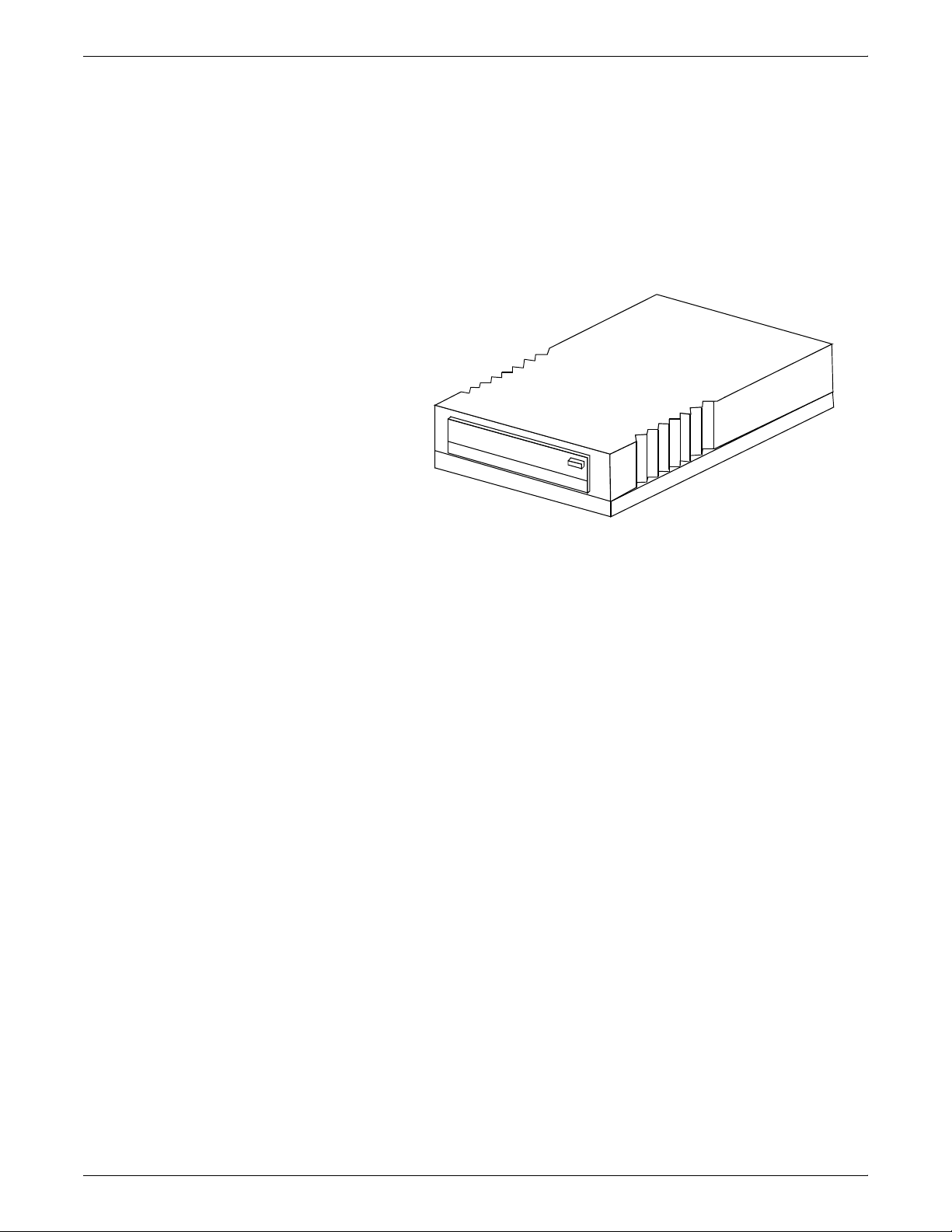
• Cartridge tape drive: A 4 GB external SCSI quarter inch
cartridge (QIC) tape drive is an external device provided with
the printing system. The cartridge tape drive connects to the
controller through the SCSI port on the processor back panel.
Like the diskette and CD drives, this tape drive is not an input
source for print jobs or for any other data or application. You
use it to load resource files, and the service representative uses
it to load system maintenance files or to save diagnostic
information.
Figure 2-4. External cartridge tape drive
• Back panel: The back panel of the processor has a power
receptacle and outlet, connectors, connector openings, and
ports. The following figure shows the back panel of the Sun
Ultra 60 workstation that is a part of your IPS controller.
2-6 XEROX DOCUPRINT 4850/4890 IPS INSTALLATION PLANNING GUIDE
Page 23
CONTROLLER COMPONENTS AND OPTIONS
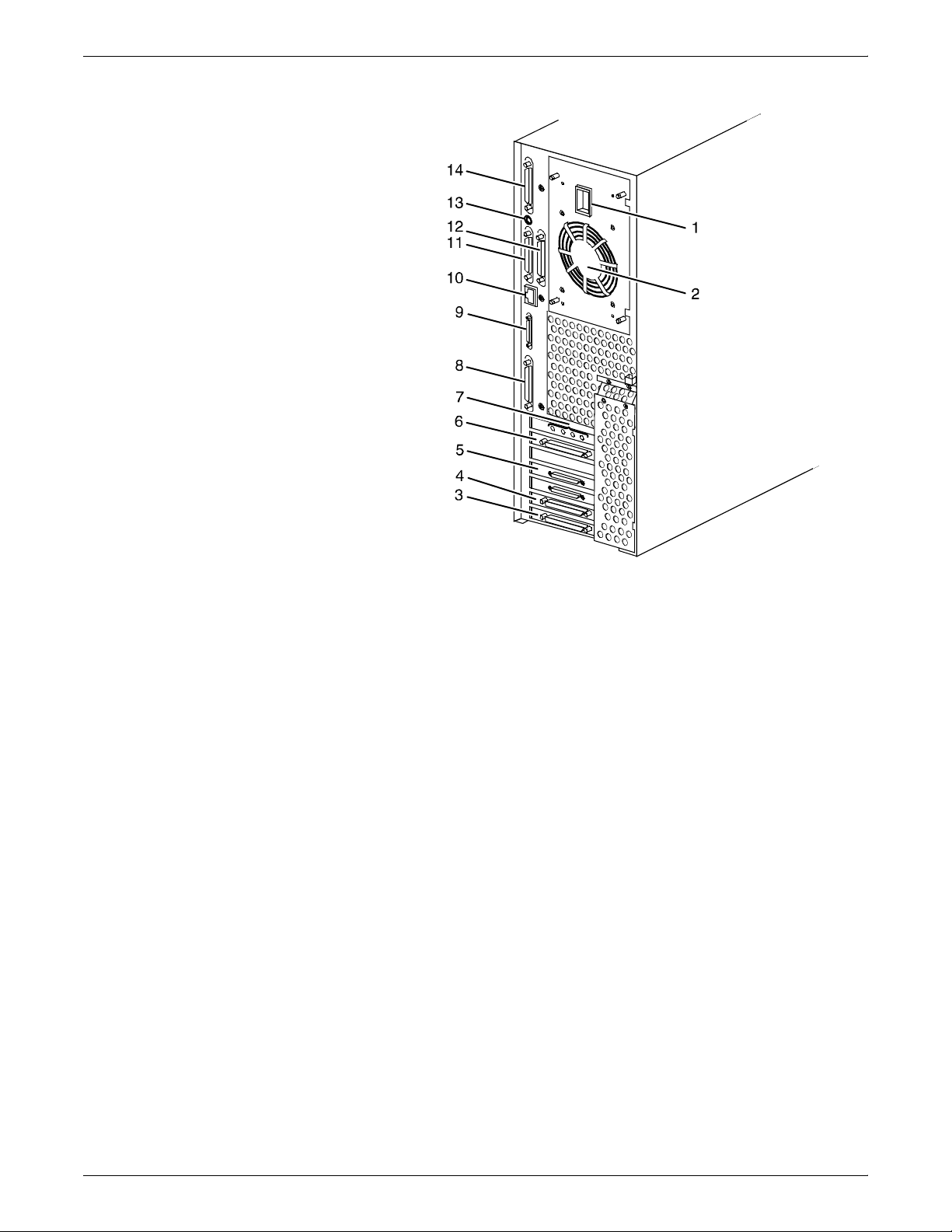
Figure 2-5. Back panel of the Sun Ultra 60 processor
1 Power inlet
2 Fan vent
3 Online interface (if configured)
4 Differential SCSI PWB (optional)
5 Printer connector (PCI66 1)
6 Monitor connector
7 Audio connectors (4)
8 Single-ended SCSI connector
9 MII connector
10 TPE (Ethernet) connector
11 Serial connector A: RS-432/RS-232
12 Serial connector B: RS-432/RS-232
13 Keyboard connector
14 Parallel connector
Display monitor The graphical user interface allows you to interact with the printer
and to monitor its interaction with the various components. During a
print job, printer error messages may display to notify you of any
unexpected conditions.
Keyboard The keyboard consists of alphanumeric keys similar to a typewriter,
symbols and special character keys, an extended character set, and
function keys. The keyboard is one of your main methods of
communicating with the printer. You can use the keyboard to make
selections, and to enter commands that control functions such as
requesting sample prints, obtaining billing meter totals, shutting down
the system, and so forth.
XEROX DOCUPRINT 4850/4890 IPS INSTALLATION PLANNING GUIDE 2-7
Page 24

CONTROLLER COMPONENTS AND OPTIONS
Mouse The mouse is another main method of communicating with the
printer. The mouse has three buttons. The left and right buttons are
used to select IPS functions. The center button provides additional
functions that you will not be required to use. If your workstation has
an optical mouse, it must remain on its designated metallic pad to be
active. If the mouse has a roller ball instead of an optical sensor
underneath, it requires a non-metallic pad.
Note: Printer controller hardware configurations are subject to
upgrade.
2-8 XEROX DOCUPRINT 4850/4890 IPS INSTALLATION PLANNING GUIDE
Page 25
IPS user interface screen
CONTROLLER COMPONENTS AND OPTIONS
The graphical user interface allows you to interact with the printer
and to monitor its interaction with the various components. During a
print job, printer error messages may display to notify you of any
unexpected conditions.
The following graphic shows the 4850/4890 IPS user interface
screen.
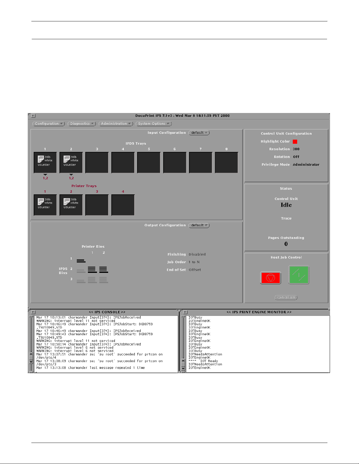
Figure 2-6. IPS user interface screen
The IPS console window displays the system messages. The IPS
print engine monitor window monitors the current printer state and
displays messages such as a broken or jammed printer, printer
ready, paper trays, engine faults, and other messages about the
condition of the printer.
XEROX DOCUPRINT 4850/4890 IPS INSTALLATION PLANNING GUIDE 2-9
Page 26
CONTROLLER COMPONENTS AND OPTIONS
The IPS main window provides access to the IPS menus and tray
grouping windows. These menus and windows in turn provide
access to the task subwindows from which system operation and
administration tasks are performed.
Host Channel Unit (HCU)—channel-attached systems only
The HCU handles all of the IPDS communications and handshaking
with PSF on the host when the IPS is receiving data over a channel.
(It is not used when the IPS is printing data using TCP/IP.) The
following figure illustrates the HCU component.
Figure 2-7. Host Channel Unit (HCU)
• The front panel of the HCU provides a single-digit LED display
which enables you to monitor power-up and offline status, and
alerts you to error conditions. (Refer to your IPS Messages
Guide for an explanation of the HCU codes displayed here.)
• The back panel of the HCU has a power switch and outlet,
S/370 bus and tag cable input and bypass connectors, and a
dual serial port. In addition, there are two switches on the back
panel to set channel printing to high or low. The power supply is
a standard switching power supply capable of 10 amps on the 5
volt output.
Note: The customer is responsible for obtaining, stringing, and
maintenance of the bus and tag cables. The bus and tag cables must
be fully populated cable sets.
2-10 XEROX DOCUPRINT 4850/4890 IPS INSTALLATION PLANNING GUIDE
Page 27

Printer components
3. 3Printer components and
options
The printer processes the electronic data and images received from
the controller and produces the printed report. This chapter
describes the components and options available for the printer.
The standard 4850 and 4890 printer components are the printer
control console, the sample tray, the feeder trays, and the stacker
trays. Labels are located throughout the printer to assist you with a
variety of tasks such as clearing a paper jam. The printer also has the
capability to sound an audible tone to direct your attention to a printer
problem. Your service representative can adjust the volume of this
tone.
The printer provides control buttons and displays for basic printer
functions and status information. The printer control console contains
message and graphic displays that assist you with jam clearance and
printer maintenance.
XEROX DOCUPRINT 4850/4890 IPS INSTALLATION PLANNING GUIDE 3-1
Page 28
PRINTER COMPONENTS AND OPTIONS
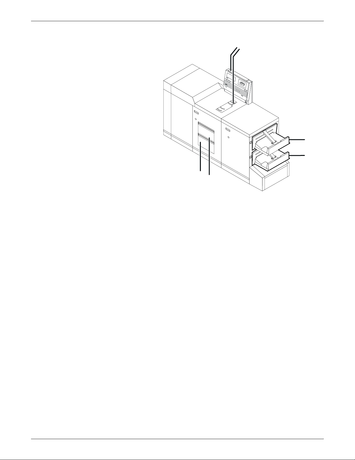
Figure 3-1. 4850/4890 printer
6
5
1
2
3
4
1 Printer control console
2 Sample tray
3 Stacker tray 1
4 Stacker tray 2
5 Feeder tray 1
6 Feeder tray 2
Refer to the System Overview manual for a detailed description of
the features and operation of the printer components.
3-2 XEROX DOCUPRINT 4850/4890 IPS INSTALLATION PLANNING GUIDE
Page 29
Printer control console
PRINTER COMPONENTS AND OPTIONS
The printer control console contains message and graphic displays,
as well as status indicator lights that alert you to printer conditions,
paper jams, and other fault and status conditions (such as low dry
ink). Other indicator lights show which feeder tray is active and the
paper size in use. These indicators and the Information button help
you to solve printer problems.
Also on this console are Stop and Continue buttons, which allow you
to stop printing and resume an interrupted job without returning to the
workstation controller. This gives you temporary control of the printer
without interrupting input processing.
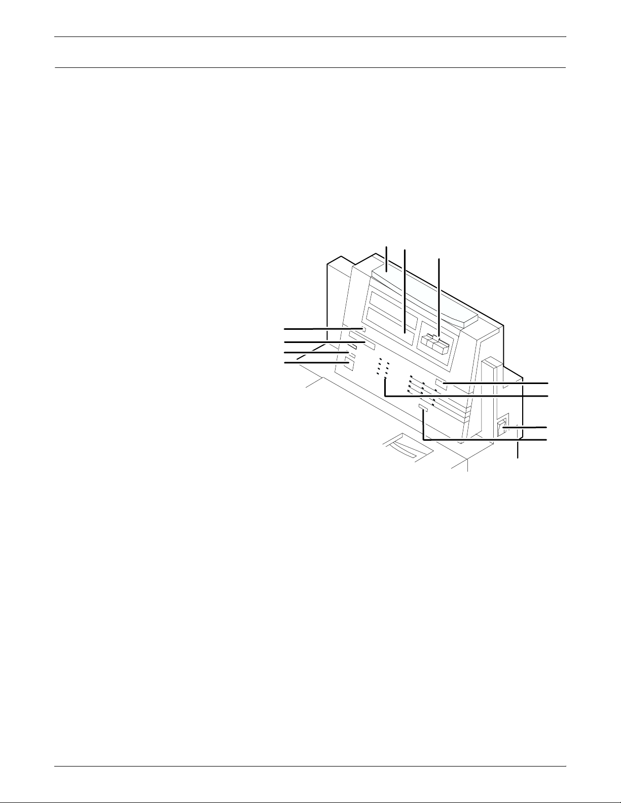
Figure 3-2. 4850/4890 printer control console
1
2
3
11
10
9
8
1 Attention light
2 Message display
3 Graphic display
4 Wire percentage indicator
5 Feeder tray indicators
6 Power on/off switch
7 Sample button (disabled)
8 Continue button
9 Stop button
10 Fault code display
11 Information button
4
5
6
7
Refer to the System Overview manual for a detailed description of
the features and operation of the printer control console components.
XEROX DOCUPRINT 4850/4890 IPS INSTALLATION PLANNING GUIDE 3-3
Page 30
PRINTER COMPONENTS AND OPTIONS
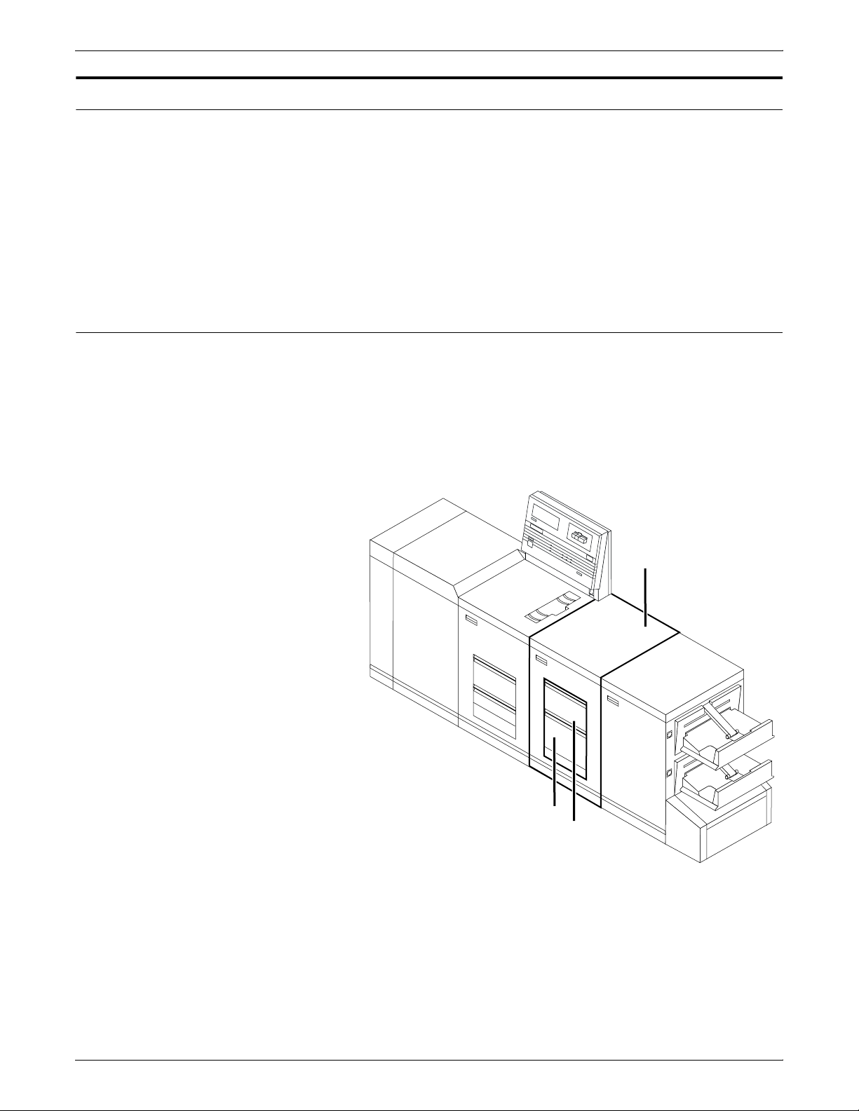
Printer options
High-capacity feeder
All 4850 and 4890 printers are available with the following options:
• High-capacity feeder
• Dual stacker or stitcher/stacker
In addition, the LPS 4890, the IPS 4890, and the NPS 4890 printers
are available with the bypass transport option.
These options allow you to customize your printing system for
increased efficiency and for specialized applications.
Two feeder trays are provided as part of the printer base
configuration (feeder trays 1 and 2). For the DocuPrint Models 4850
and 4890, the high-capacity feeder option increases the versatility
and productivity of the printer with two additional feeder trays (trays
3 and 4), increasing the feeder capacity by approximately 2,000
sheets.
Figure 3-3. 4850/4890 with high-capacity feeder
1
3
2
1 High-capacity feeder module
2 Feeder tray 3
3 Feeder tray 4
Tray capacities Each high-capacity feeder tray holds 1,000 sheets of 20-pound or 80
gsm bond paper.
3-4 XEROX DOCUPRINT 4850/4890 IPS INSTALLATION PLANNING GUIDE
Page 31

Dual stacker
PRINTER COMPONENTS AND OPTIONS
Paper sizes Both high-capacity feeder trays handle paper sizes from 8 by 10
inches / 203 by 254 mm to 8.5 by 14 inches / 216 by 356 mm. This
includes international paper size A4 (8.27 by 11.16 inches / 210 by
283 mm).
The dual stacker contains two identical output trays in which it can
offset jobs or reports. Using the output configuration windows on the
graphical user interface, you can send output to either or both of
these trays in the desired order.
Figure 3-4. 4850/4890 with dual stacker
1
2
3
1 Sample tray
2 Stacker tray 1
3 Stacker tray 2
Tray capacities Stacker trays 1 and 2 each hold up to 750 sheets of 20-pound or 80
gsm bond paper.
XEROX DOCUPRINT 4850/4890 IPS INSTALLATION PLANNING GUIDE 3-5
Page 32

PRINTER COMPONENTS AND OPTIONS
Stitcher/stacker
The stitcher/stacker can place a wire stitch or staple in stacks of up
to 50 sheets. It contains a single output tray in which it can offset jobs
and reports.
Figure 3-5. 4850/4890 with stitcher/stacker
1
1 Sample tray
2 Stitcher/stacker tray
Tray capacities The stitcher tray holds:
• Up to 2,000 sheets of 20-pound or 80 gsm bond, unstitched
• Up to 200 two-sheet stitched sets
Up to 50 sheets can comprise each stitched set. The wire supply
provides up to 32,000 staples.
2
3-6 XEROX DOCUPRINT 4850/4890 IPS INSTALLATION PLANNING GUIDE
Page 33

Customer-changeable unit (CCU)
PRINTER COMPONENTS AND OPTIONS
The customer-changeable unit (CCU) contains the replaceable
colored dry ink dispenser bottle and the color developer housing. It is
a self-contained unit that is easily removed from the printer and
stored until needed. Each bottle is uniquely coded to the color of the
housing to ensure that a wrong color is not added to a housing.
Note: Only the color housing can be changed. The black housing
is permanently installed in the printer, and only the ink and developer
bottles are changed.
A changeout cart is used to remove a CCU from the printer and to
transport a CCU to the printer or to another area. Because of the
physical weight of the CCU, the cart is required to change colored dry
ink.
The cart also serves as a storage device for CCUs that are not
currently in use. For example, if you use both the red and blue inks
in your operation, one CCU is always out of the machine in storage
on the cart while the other CCU is installed.
Figure 3-6. Changeout cart with CCU installed
Note: You should have a cart for each CCU, so that one cart is
always empty and available to remove the CCU installed in the
system. However, if your printer is used to print only one color—the
CCU will never be removed—or if there is more than one 4850/4890
printer in operation at your site, it may not be necessary to have one
cart for each CCU. Consult your site representative for more
information.
XEROX DOCUPRINT 4850/4890 IPS INSTALLATION PLANNING GUIDE 3-7
Page 34

PRINTER COMPONENTS AND OPTIONS
Bypass transport option (4890 only)
The bypass transport enables third-party finishing equipment to
connect to and interface directly with the 4890. It requires that your
4890 have a dual stacker output module configuration. Likewise,
third-party finishing devices require a bypass transport to interface
with the 4890.
The bypass transport option enables individual printed sheets of
paper to pass through the 4890 output module to third party finishing
equipment. The third party devices perform a variety of finishing
tasks such as saddle-stitching, binding, folding, stapling, trimming,
and stacking. These are usually stand-alone devices that can be
connected in any number of configurations.
Figure 3-7. 4890 with bypass transport
1
2
1 Bypass transport
2 Bypass transport support
The bypass transport fits into tray 1 of the dual stacker. With the
bypass transport, sheets of paper flow from left to right (when viewed
from the front of the printer), leading from the long edge of each
sheet. You can configure the output module to run with or without the
bypass transport. The bypass transport support is stationary and
cannot be removed. However, the support does not interfere with the
operation of trays 1 or 2 when the bypass transport is removed.
3-8 XEROX DOCUPRINT 4850/4890 IPS INSTALLATION PLANNING GUIDE
Page 35

PRINTER COMPONENTS AND OPTIONS
Figure 3-8. Third party finishing device configuration
1
1 Paper path
2 Bypass transport
3 Third-party finishing devices
It is important to note that while the bypass transport option provides
you with an interface between your DocuPrint 4890 IPS and your
finishing accessories, the finishing accessories require their own AC
and DC power sources. The power must be independent of your
DocuPrint 4890 IPS.
More information on the bypass transport and document finishing
can be obtained from the Xerox Finishing web site
http://www.xerox-finishing.com/
2
3
Interface with third-party devices
Electrical interface
Included on this web site are the DFA Interface Specifications for
your printer.
Consult your Xerox sales representative, as well as the sales
representative of the company from which you purchased your
finishing equipment, for specific electrical and space requirements.
The mechanical interface between the laser printing and third-party
finishing devices can connect as follows:
• Physically aligning a finishing device with the exit slot of the
bypass transport exit slot.
• Docking the third-party finishing device to the bypass transport
and establishing a mechanical and electrical interface between
the two.
When you power up the 4890, the printer automatically detects the
presence of the bypass transport and external finishing devices. The
system also begins monitoring the interlocks (physical links) between
the bypass transport and the finishing device and starts finishing
device interface communications.
XEROX DOCUPRINT 4850/4890 IPS INSTALLATION PLANNING GUIDE 3-9
Page 36

PRINTER COMPONENTS AND OPTIONS
Your 4890 and third-party finishing devices interface on several
different levels:
• The 4890 requires information about the finishing devices to
store in its non-volatile memory (NVM).
• The finishing device information is grouped into a personality
profile for each device.
• Your operators prepare the third-party device hardware to finish
the printed output and inform the 4890 of device names and
parameters.
• The bypass transport feeds single sheets of paper to the
external finishing device.
• Communications between the bypass transport and the
external finishing device consist of command and status
signals.
3-10 XEROX DOCUPRINT 4850/4890 IPS INSTALLATION PLANNING GUIDE
Page 37

4. 4Preparing for installation
This chapter assists you in preparing for the installation of your Xerox
DocuPrint 4850 and 4890 IPS.
Preparing for installation is a responsibility shared by personnel at
your site and Xerox. Your service representatives are available to
discuss installation issues and to assist you in completing the site
installation tasks.
Prior to installation, you must select and prepare an appropriate
location for the DocuPrint system and order supplies. This chapter
helps you accomplish these tasks by providing the following
information:
• A summary of your responsibilities and those of your Xerox
service representative
• Connectivity requirements for setting up the IPS to receive data
from the IBM host
• A checklist of installation planning activities.
Responsibilities
Xerox responsibilities
For information on controller power and space requirements, refer to
the “Controller specifications and requirements” chapter of this guide.
For facts about printer power and space requirements, refer to the
“Printer specifications and requirements” chapter of this guide.
This section describes your site responsibilities and the
responsibilities of your service representatives. Included are some
joint responsibilities.
This section lists the responsibilities of the service representatives
and system analysts prior to, during, and after installation:
• Site selection
— Assist in site selection
— Inspect and approve the site.
• Installation
— Schedule the delivery of the hardware
— Monitor installation activities
— Assist you in ordering any supplies required
— Configure system parameters
XEROX DOCUPRINT 4850/4890 IPS INSTALLATION PLANNING GUIDE 4-1
Page 38

PREPARING FOR INSTALLATION
Customer responsibilities
— Assist with the entry of DFA personality profiles for use with
third-party finishing devices (4890 IPS only)
— Create default input and output configurations for your
system
— Install the DocuPrint system.
• Training
— Provide initial operator training
— Provide information and assistance in registering for Xerox
Customer Education classes or obtaining tutorials.
• Service
— Review preventive maintenance schedules and service call
procedures
— Provide ongoing maintenance
— Assist in resolving hardware and software problems.
Your responsibilities prior to, during, and after installation of the IPS
are to schedule and monitor your installation activities:
• Site personnel
— Identify the person at your site who will be the primary
interface with Xerox
— Make sure the on-site primary interface is available to the
service representative before and during the installation.
• Site preparation
— Select and prepare the site for the IPS installation
(including proper power, air conditioning, and work space)
— Install Ethernet or Token Ring to system location
— Obtain the necessary interfaces, cables, transceivers,
and so forth
Note: You are responsible for obtaining, stringing, and
maintaining fully-populated bus and tag cables for channelattached systems.
— Plan and schedule installation activities
— Convert any host-resident fonts to 300 dpi
— For channel-attached systems: Provide your host channel
address to your Xerox representative
— Sysgen your host to print to an AFP Type1, Group 3 printer.
Refer to your IBM documentation for further information
— For stitcher/stacker option: Work with your service
representative to determine the “low wire” percent values
to be displayed on the printer control console
— Provide a list of the stocks you want in your default input
tray configuration
4-2 XEROX DOCUPRINT 4850/4890 IPS INSTALLATION PLANNING GUIDE
Page 39

PREPARING FOR INSTALLATION
— Review this IPS Installation Planning Guide thoroughly
— Have the required parameters defined for configuring PSF
to print on the IPS. Refer to the “Defining the channel
attached printer to the host” or the “Defining the printer to
the host: TCP/IP attachment” appendix of this guide for
examples and explanations of these parameters.
• Training
— Select the personnel to undergo operator training
— Set up the operator training schedules.
• Applications
— Work with your Xerox system analyst to determine
requirements for the initial applications
— In a mixed environment, where there is a variety of printing
systems, discuss print quality differences with your service
representative.
Make sure that your system specialists are familiar with the operating
system software specific to your IPS; operating system software is
not the same for all laser printing systems. If your system specialists
are familiar with one of these operating systems and you are
converting to or adding another, they should be aware of the
differences.
XEROX DOCUPRINT 4850/4890 IPS INSTALLATION PLANNING GUIDE 4-3
Page 40

PREPARING FOR INSTALLATION
Installation planning checklist
To aid you in printer installation planning, the following is a checklist
that lists the tasks that you and your service representative must
complete before installation. If you have questions about any of these
activities, contact your sales or service representative.
Use the time frames in this checklist as guidelines. It is best to consult
your suppliers to determine the required lead times.
Table 4-1. 4850/4890 IPS installation planning checklist
Date
Week Activity Reference Responsibility
-4 Select location for the 4850/4890 IPS. Chapters 5 and 6 Customer ________
completed
Order additional documentation, if necessary. Call XDSS at 1-
800-327-9753;
see Appendix B
(U.S. only)
Register for Xerox Customer Education classes
and order tutorials, if necessary.
Schedule printer delivery. Xerox ________
Convert your IBM host-resident fonts to 300 dpi. Customer ________
-3 Schedule hardware delivery. Sales rep. Customer and Xerox ________
Prepare site:
Appendix B Customer and Xerox ________
Chapters 4, 5 and 6Customer ________
• Provide a table with adequate space for
hardware and cables.
• Ensure proper electrical outlets are
installed.
• Install Token Ring to system location (if
appropriate).
Customer ________
________
________
________
________
________
• Install Ethernet (if appropriate).
• Ensure proper operating environment.
________
• Obtain and string bus and tag cables (must
be fully populated), if needed.
• Generate the host for an AFP1 device and
IPL, as required.
4-4 XEROX DOCUPRINT 4850/4890 IPS INSTALLATION PLANNING GUIDE
Page 41

PREPARING FOR INSTALLATION
Table 4-1. 4850/4890 IPS installation planning checklist
(continued)
Date
Week Activity Reference Responsibility
-2 Inspect and approve site. Xerox ________
completed
Order consumable supplies. Minimum supplies
needed for installation:
• Paper (2 cartons)
Chapter 4,
Appendix A and
sales rep
• Developer, black (1 carton) No. 502S63250
• Developer, colored (1 carton each color)
• Fuser lubricant (2 cartons) No. 8R983
• Dry ink, black (1 carton) No. 6R296
• Dry ink, colored (1 carton each color).
Note: After installation, you will need to
establish a procedure for ordering supplies
according to your ongoing production
requirements.
-1 Schedule operator training. Systems analyst
(U.S.) or site
representative
(non-U.S.)
Define parameters needed to configure PSF for
connectivity to the IPS printer.
Install Make sure supplies are available. Chapter 4 and
Appendix D and E Customer ________
Appendix A
Customer and Xerox ________
Customer and Xerox ________
Customer
Make sure system administrators are available
during software installation.
Provide host channel address and channel unit
address (if printing via channel).
Provide host IP address. Appendix D and E Customer ________
Sysgen your host to print to an AFP Type 1,
Group 3 printer.
Set up Data Transfer Mode. Customer and Xerox ________
Install 4850/4890 IPS printer hardware and
software.
Have operators available for training. Appendix E Customer ________
Check documentation and software kits for
completeness.
Have test jobs ready to run. Customer ________
Provide stocks needed for default input
configuration
Provide parameters needed to configure PSF
for connectivity to the IPS printer.
Appendix D or E Customer ________
Customer ________
Customer ________
Customer and Xerox ________
Xerox ________
Customer ________
Customer ________
XEROX DOCUPRINT 4850/4890 IPS INSTALLATION PLANNING GUIDE 4-5
Page 42

PREPARING FOR INSTALLATION
Table 4-1. 4850/4890 IPS installation planning checklist
(continued)
Week Activity Reference Responsibility
Date
completed
Postinstall
Become familiar with support services. Appendix B Customer ________
Establish supplies maintenance procedure. Appendix A Customer ________
Provide ongoing 4850/4890 IPS maintenance. Guide to
Customer and Xerox ________
Performing
Routine
Maintenance
Order additional documentation, as necessary. Appendix B Customer ________
Adjust the IOT alignment and magnification. Xerox ________
4-6 XEROX DOCUPRINT 4850/4890 IPS INSTALLATION PLANNING GUIDE
Page 43

Connectivity requirements
Ethernet specifications
PREPARING FOR INSTALLATION
A Token Ring network or an Ethernet local area network running
TCP/IP is the network communication system that may be used to
transport documents from the host to the IPS. This is an alternative
to the channel-attached configuration, in which data is transmitted via
bus and tag cables and the HCU.
The Ethernet connection to the printer controller processor must be
compatible with the Institute of Electrical and Electronics Engineers
(IEEE) 802.3 standard.
The Ethernet interface on the processor is a 10Mb/sec twisted pair
standard (10BaseT and 100BaseT). The MII (for UltraSPARC) Coax
Ethernet is enabled with an adapter cable.
The Ethernet interface on the printer controller processor is a 10Mb/
sec twisted pair standard (10BaseT and 100BaseT). Attachment Unit
Interface (AUI) Coax Ethernet is enabled with an adapter cable.
Token Ring specifications
Work with your system administrator to assess what type of network
you have and what modifications need to be made to supply an
Ethernet connector to the printer controller processor.
The Token Ring connection must be compatible with the IEEE 802.3
standard. The printer controller processor has a 4 MB / 16 MB Token
Ring Auto interface (16 MB is preferred).
XEROX DOCUPRINT 4850/4890 IPS INSTALLATION PLANNING GUIDE 4-7
Page 44

PREPARING FOR INSTALLATION
4-8 XEROX DOCUPRINT 4850/4890 IPS INSTALLATION PLANNING GUIDE
Page 45

Power requirements
5. 5Controller specifications and
requirements
This chapter provides power and space requirements for your
4850/4890 IPS printer controller. It also provides controller
environmental specifications.
For facts about printer power and space requirements, refer to the
“Printer specifications and requirements” chapter of this guide.
Your 4850/4890 IPS controller has important power requirements
that must be accommodated. These requirements are summarized in
the table below.
For details on printer power requirements, refer to the “Printer
specifications and requirements” chapter of this guide.
Table 5-1. 4850/4890 IPS controller 60 Hz
electrical requirements
Amp
Voltage
Sun Ultra 2 printer controller 100 to 240 VAC 15 amp 0.4 KVA 5-15R
HCU 100 to 240 VAC 15 amp 0.4 KVA 5-15R
Sun Ultra 60 printer controller 100 to 240 VAC 15 amp. 0.4 KVA 5-15R
Table 5-2. 4850/4890 IPS controller 50 Hz
electrical requirements
Voltage
Sun Ultra 2 printer controller 100 to 240 VAC 15 amp 0.4 KVA
HCU 100 to 240 VAC 15 amp 0.4 KVA
Sun Ultra 60 printer controller 100 to 240 VAC 15 amp 0.4 KVA
service KVA rating NEMA
Amp.
service KVA rating
Agency certification: UL 478 and 1950, IEC 950, CSA 22.2 #220-
1986, FCC (Class A), and VDE 0871 (Class A).
XEROX DOCUPRINT 4850/4890 IPS INSTALLATION PLANNING GUIDE 5-1
Page 46

CONTROLLER SPECIFICATIONS AND REQUIREMENTS
Outlet configurations
This section discusses specifications for system outlets and the
required wall outlet configurations for the USA/Canada and
internationally.
Note: All power outlets must be dedicated to this equipment. When
determining the electrical connections for your printing system, make
sure that:
• Each power cord has a separate circuit
• The printer power cord configurations match your receptacle
• Your electrical outlets are within the required specifications.
50 Hz systems: Ensure that power connections are per local codes/
regulations.
The following figure shows a 60 Hz American and Canadian wall
outlet in which to plug the printer controller and HCU.
Figure 5-1. 60 Hz wall outlet
12
3
1 AC Hot (ACH)
2 AC Hot (ACH)
3 Earth Ground (GND)
The required American and Canadian wall outlet voltage is 100 to
120 VAC between AC hot and neutral, and between AC hot and GND.
The voltage is less than three VAC between GND and neutral.
Refer to the 60 Hz and 50 Hz controller electrical requirements tables
earlier in this chapter for a description of the power specifications for
the controller.
Warning: To reduce the risk of electrical shock, do not plug
!
components into any other type of power system. Contract your
facilities manager or a qualified electrician if you are not sure what
type of power is supplied to your work area.
5-2 XEROX DOCUPRINT 4850/4890 IPS INSTALLATION PLANNING GUIDE
Page 47

Environmental specifications
CONTROLLER SPECIFICATIONS AND REQUIREMENTS
Heat dissipation specifications for the 4850/4890 IPS controller are
shown in the table below.
For recommended environmental ranges for the printer work area,
refer to the “Printer specifications and requirements” chapter of this
guide.
Table 5-3. Heat dissipation specifications for the 4850/4890
IPS controller
Heat dissipation
Processor/monitor 1,100 BTU per hour
HCU 408 BTU per hour
XEROX DOCUPRINT 4850/4890 IPS INSTALLATION PLANNING GUIDE 5-3
Page 48

CONTROLLER SPECIFICATIONS AND REQUIREMENTS
Space requirements
Printer controller placement
The printer controller consists of the Sun workstation and, for
channel-attached systems, the HCU. This section provides
recommendations for placement of controller hardware components.
For printer component space requirements, refer to the “Printer
specifications and requirements” chapter of this guide. Contact your
service representative if you have questions not specifically
addressed in this guide.
You should consider the following factors when deciding where to
place the DocuPrint printer controller:
• Adequate work space and service clearance around the
equipment
• Proximity to electrical and network connectors
• Security of the work area. You may need to place the system in
an area where you can restrict access to it.
The printer controller consists of the Sun workstation and, for
channel-attached systems, the HCU. You must supply a table or
desk as a work surface for both the printer controller and the HCU.
The top of the table must provide at least 36 by 36 inches / 91 by 91
cm of space for each component, to allow enough space for the
components and cables, as well as for service access.
Refer to the “4850/4890 IPS printer controller specifications and
power requirements” summary table at the end of this chapter to
make sure the tables you supply can support the weight of the printer
controller hardware elements and of the HCU, and that they are
suitable for the intended use.
Warning: The printer controller must be positioned within the line-
!
of-sight of the printer for safety purposes while servicing the
equipment.
Caution: Position the table at least 6 inches / 15.2 cm from the wall.
Make sure the workstation processor and the HCU are at least
12 inches / 30.4 cm from the wall. Do not put the processor or the
HCU on the IPS printer.
!
5-4 XEROX DOCUPRINT 4850/4890 IPS INSTALLATION PLANNING GUIDE
Page 49

CONTROLLER SPECIFICATIONS AND REQUIREMENTS
Sun Ultra 2 workstation placement Following are guidelines for placement of the Sun Ultra 2 workstation
components of the printer controller.
Figure 5-2. Sun Ultra 2 printer controller hardware
1 Mouse and mouse pad
2 Keyboard
3 Monitor
4 Processor
5 Table
When you place your workstation processor on a table top, make
sure to allow at least 6 inches / 152 mm of unobstructed space at the
rear and both sides of the processor. Do not allow any piece of
equipment to blow warm air into the air-intake vents of the processor.
Caution: Do not place a monitor with a base larger than the
processor on top of the unit. Do not block any fan or vents on the
sides or rear of the processor.
XEROX DOCUPRINT 4850/4890 IPS INSTALLATION PLANNING GUIDE 5-5
Page 50

CONTROLLER SPECIFICATIONS AND REQUIREMENTS
Sun Ultra 60 workstation placement Following are guidelines for placement of the Sun Ultra 60
workstation components of the printer controller.
Figure 5-3. Sun Ultra 60 printer controller hardware
1 Mouse and mouse pad
2 Keyboard
3 Monitor
4 Processor
5 Table
To ensure consistent performance and avoid any damage to
equipment, follow these rules for placing the components of the Sun
Ultra 60 controller.
Do:
• Place the monitor and processor on a desk or table top,
separate from the printer. The monitor should be placed beside
the processor, on the same surface. (The cartridge tape drive
may be placed on top of the processor.)
• Keep the processor in an upright, vertical position as illustrated
below.
• Allow at least 6 inches / 152 mm of unobstructed space at the
front and rear of the processor, so the fan and vents are not
blocked.
5-6 XEROX DOCUPRINT 4850/4890 IPS INSTALLATION PLANNING GUIDE
Page 51

CONTROLLER SPECIFICATIONS AND REQUIREMENTS
The following illustration shows fan and vent locations on the
front and back of the controller.
Figure 5-4. Sun Ultra 60 fan and vent locations to keep clear
1 Vent in front of processor
2 Fan in back of processor
3 Vent in back of processor
Do not:
• Do not place the controller monitor on top of the processor.
• Do not allow any piece of equipment to blow warm air into the
air intake vents of the processor.
• Do not place the processor on its side, or in any other position
but the upright, vertical position shown in the previous figure.
• Do not place the processor or monitor on top of the printer.
XEROX DOCUPRINT 4850/4890 IPS INSTALLATION PLANNING GUIDE 5-7
Page 52

CONTROLLER SPECIFICATIONS AND REQUIREMENTS
HCU placement (channel-attached
systems only)
The following shows the recommended HCU hardware placement,
for channel-attached systems.
Figure 5-5. IPS HCU hardware (for channel-attached systems)
1 HCU
2 Table
Dimensions of the 4850/4890 printer controller with the 9-track
magnetic tape drive measurements are shown in the following table.
5-8 XEROX DOCUPRINT 4850/4890 IPS INSTALLATION PLANNING GUIDE
Page 53

CONTROLLER SPECIFICATIONS AND REQUIREMENTS
Controller hardware specifications and requirements summary
The following table summarizes the specifications and electrical
requirements of your DocuPrint IPS printer controller hardware
components.
For a summary of printer hardware specifications and requirements,
refer to the “Printer specifications and requirements” chapter of this
guide. Contact your service representative if you have questions not
specifically addressed in this guide.
Table 5-4. 4850/4890 IPS printer controller specifications and
power requirements
Dimensions (depth,
Device
Host Channel
Unit (HCU)
(channelattached
systems only)
Processor d=16.1 in. / 40.9 cm
width, height) Weight
d=15 in. / 40.8 cm
h=5 in. / 12.6 cm
w= 16 in. / 41.6 cm
w=16.4 in. / 41.7 cm
h= 3 in. / 7.6 cm
26 lbs. 10
oz. / 12.4
kgs
27 lbs. /
12.7 kgs
Heat
dissipation Power requirements Cable lengths
N/A 120 VAC within 6 feet;
120 volt at 2 amps or
240 volt at 1 amp
1,100 BTU
per hours
Sun Ultra 2 (60 Hz):
100 to 240 VAC,
15 amp, 0.4 KVA,
5-15 NEMA
Sun Ultra 2 (50 Hz):
100 to 240 VAC,
15 amp, 0.4 KVA
Sun Ultra 60 (60 Hz):
100 to 240 VAC,
15 amp, 0.4 KVA,
5-15 NEMA
Bus and tag
cables must
conform to host
system
requirements
(200 to 400 ft. /
66.7 to 133.3 m)
and
accommodate
system setup.
Power: 8 ft. /
2.4 m
Interface to
printer:
20 ft. / 6.1 m
usable length
Sun Ultra 60 (50 Hz):
100 to 240 VAC,
15 amp, 0.4 KVA
Monitor d=6.1 in. / 41cm
w=20 in. / 50.8 cm
h=17.7 in. / 45 cm
4 mm cartridge
tape drive
XEROX DOCUPRINT 4850/4890 IPS INSTALLATION PLANNING GUIDE 5-9
d=12.2 in. / 31 cm
w=7.5 in. / 19 cm
h=2.8 in. / 7 cm
61 lbs. /
27.7 kg
8 lbs. /
6.6 kg
408 BTU
per hour
--- 100-120/200-240 VAC,
100-120 ~ VAC,
1 phase, 50-60 Hz,
3.0 amp, 0.4 KVA
200-240 ~ VAC,
1 phase, 50-60 Hz,
2.0 amp, 0.4 KVA
0.8/0.4 amp, 47-63 Hz
Video cable to
processor:
46 in. / 1.17 m
SCSI cable to
processor or
additional SCSI
device:
28 in. / 71 cm
Page 54

CONTROLLER SPECIFICATIONS AND REQUIREMENTS
Table 5-4. 4850/4890 IPS printer controller specifications and
power requirements (continued)
Dimensions (depth,
Device
width, height) Weight
Keyboard d=7.5 in. / 19.1 cm
w=20 in. / 50.8 cm
Mouse d=3 in. / 8 cm
w=4 in. / 10 cm
h=2 in. / 5 cm
Heat
dissipation Power requirements Cable lengths
2 lbs. / 1kg --- --- 72 in. / 1.8 m
0.3 lbs. /
--- --- 25 in. / 63 cm
0.14 kg
5-10 XEROX DOCUPRINT 4850/4890 IPS INSTALLATION PLANNING GUIDE
Page 55

Power requirements
6. 6Printer specifications and
requirements
This chapter provides power and space requirements for your
4850/4890 printer. It also provides printer environmental
specifications.
For facts about controller power and space requirements, refer to the
“Controller specifications and requirements” chapter of this guide.
Your DocuPrint system has important power requirements that must
be accommodated. These requirements are summarized in the table
below. For further details on power requirements, refer to the voltage
charts and wiring diagrams that follow.
For details on controller power requirements, refer to the “Controller
specifications and requirements” chapter of this guide.
Table 6-1. 4850 printer 60 Hz electrical requirements
Voltage Amp. service KVA rating NEMA
120/208 or 120/240 VAC 30 amp Operating: 4.1
Standby: 2.7
Table 6-2. 4850 printer 50 Hz DELTA electrical requirements
Voltage Amp. service KVA rating
220, 230, 240 VAC
(3 phase, 4 wire or
single-phase)
Table 6-3. 4890 printer 60 Hz electrical requirements
Voltage Amp. service KVA rating NEMA
120/208 or 120/240 VAC 30 amp Operating: 5.5 14-30R
Table 6-4. 4890 printer 50 Hz DELTA electrical requirements
Voltage Amp. service KVA rating
30 amp Operating: 3.8
Standby: 2.5
14-30R
220, 230, 240 VAC 30 amp Operating: 5.5
Agency certification: UL 478 and 1950, IEC 950, CSA 22.2 #2201986, FCC (Class A), and VDE 0871 (Class A).
XEROX DOCUPRINT 4850/4890 IPS INSTALLATION PLANNING GUIDE 6-1
Page 56

PRINTER SPECIFICATIONS AND REQUIREMENTS
Outlet configurations
Printer outlet voltages—60 Hz
This section discusses specifications for the DocuPrint system
outlets and the required wall outlet configurations for the USA /
Canada and internationally.
Note: All power outlets must be dedicated to this equipment. When
determining the electrical connections for your system, make sure
that:
• Each power cord has a separate circuit
• The printer power cord configurations match your receptacle
• Your electrical outlets are within the required specifications.
50 Hz systems: Ensure that power connections are per local codes/
regulations.
The following table shows the voltages for the outlets on your printing
system. All power outlets must have a dedicated circuit for each
system equipment piece.
Table 6-5. 60 Hz voltage requirements at power outlet
Measurement of wiring Nominal Range
Line 1 to neutral 120 V 105 to 127 V
Line 2 to neutral 120 V 105 to 127 V
Neutral to ground 0 V 0 to 10 V
Line 1 to line 2 208 V 181 to 220 V
Line 1 to ground 120 V 105 to 127 V
Line 2 to ground 120V 105 to 127 V
Printer power cord configurations The following figure shows the 60 Hz power cord configuration for
30 amp NEMA 14-30R. Voltage to ground is shown for
troubleshooting purposes.
Figure 6-1. 60 Hz power configuration
NEMA
14-30R
0 to 10 VAC
105 to 127 VAC
105 to
127 VAC
105 to 127 VAC
Neutral
Line 1
Ground
181 to 220 VAC
6-2 XEROX DOCUPRINT 4850/4890 IPS INSTALLATION PLANNING GUIDE
105 to 127 VAC
Line 2
Page 57

PRINTER SPECIFICATIONS AND REQUIREMENTS
Printer outlet voltages—50 Hz
All power outlets must have a dedicated circuit for each system
equipment piece. Make sure each power cord has a separate circuit.
50 Hz systems: Ensure that power connections are per local codes/
regulations.
Single phase DELTA configurations For 50 Hz DELTA configurations, measure the DELTA connection
voltages at the power source.
Table 6-6. 50 Hz single phase DELTA outlet voltage
requirements
Wiring Nominal Range
Line to neutral 220 VAC
230 VAC
240 VAC
Neutral to ground 0 VAC <10 VAC
Three-phase DELTA configurations The current carrying conductors available for 50 Hz, three-phase,
DELTA are:
198-242 VAC
207-253 VAC
216-264 VAC
• Three-phase
• Safety ground.
Table 6-7. 50 Hz three-phase DELTA outlet voltage
requirements
Nominal Phase to phase
220 VAC
230 VAC
240 VAC
Note: If one of the phases is connected to ground in the service
system, it should be connected to the neutral terminal of the printer.
In this case, the line is not a true neutral, and voltage between all
current carrying conductors is equal and mutually 120 degrees out of
phase.
198-242 VAC
207-253 VAC
216-264 VAC
XEROX DOCUPRINT 4850/4890 IPS INSTALLATION PLANNING GUIDE 6-3
Page 58

PRINTER SPECIFICATIONS AND REQUIREMENTS
Environmental specifications
When you select a site location for your DocuPrint printer, avoid
environments with extreme variations in temperature and other
hazards, such as excessive dust or humidity. Recommended
environmental ranges for the work area are as follows:
Table 6-8. Environmental specifications for 4850/4890
Condition Range
Temperature: Recommended:
Minimum:
Maximum:
Humidity: Recommended:
Minimum:
Maximum:
Altitude: Normal:
Maximum:
4850 Printer - 60 Hz heat dissipation Operating:
Standby:
4850 Printer - 50 Hz DELTA heat dissipation: Operating:
Standby:
4890 Printer - 60 Hz heat dissipation: Operating:
Standby:
4890 Printer - 50 Hz DELTA heat dissipation: Operating:
Standby:
72° F ± 4° F
22° C ± 2° C
60° F / 15.5 °C
80° F / 26.7° C
45% ±10%
30%
65%
Up to 6,000 feet / 1,830 m
above sea level
9,000 feet / 2,743 m above
sea level.
11,200 BTU/hour
7,400 BTU/hour
11,200 BTU/hour
7,400 BTU/hour
14,980 BTU/hour
9,100 BTU/hour
14,980 BTU/hour
9,100 BTU/hour
6-4 XEROX DOCUPRINT 4850/4890 IPS INSTALLATION PLANNING GUIDE
Page 59

Space requirements
PRINTER SPECIFICATIONS AND REQUIREMENTS
You should consider the following factors when deciding where to
place the printer hardware components:
• Adequate work space and service clearance around the
equipment
• Proximity to electrical and network connectors
• Security of the work area. You may need to place the system in
an area where you can restrict access to it. This may be
important if your personnel need to print confidential documents
or if you are concerned with unauthorized usage.
Dimensions and weights of the printer components are listed in this
section, along with diagrams, to help you visualize the sizes and total
space requirements.
Warning: The printer controller must be positioned within the line-
!
of-sight of the printer for safety purposes while servicing the
equipment.
!
Printer placement
Note: There must be a 78-inch / 198-cm vertical clearance
throughout the entire area. In addition, your printer must be installed
in a fixed location with a minimum clearance space of 36 inches /
91.4 cm around all sides of each piece of equipment for access by
service personnel.
For information on clearance space and other space planning
considerations, refer to the “Space planning guidelines” section of
this chapter. Contact your service representative if you have
questions not specifically addressed in this guide.
The following configurations are available for your Xerox DocuPrint
4850/4890 printer:
• Standard (two-tray) feeder with dual stacker
• Standard (two-tray) feeder with stitcher/stacker
• High-capacity feeder (HCF) with dual stacker
• HCF with stitcher/stacker.
Note: Additional space (6-inch by 64-inch / 15 cm by 163 cm) is
required in front of the printer for CCU changeout cart
operability.
XEROX DOCUPRINT 4850/4890 IPS INSTALLATION PLANNING GUIDE 6-5
Page 60

PRINTER SPECIFICATIONS AND REQUIREMENTS
Printer with standard (two-tray) feeder
and dual stacker
The dimensions of the printer with a standard (two-tray) feeder and a
dual stacker are as follows:
Dimension Specifications
Width:
Depth:
Height:
Total weight:
Total space requirement:
91.8 inches / 233 cm
35.7 inches / 91 cm
41 inches / 104 cm
1,454 pounds / 661 kg
164 by 106.5 inches /
417 by 271 cm
The following diagram illustrates a top view of the space
requirements for the printer with a standard (two-tray) feeder and
dual stacker configuration.
Figure 6-2. Printer with dual stacker
1
36 in / 91 cm
35.7 in / 91 cm
34.8 in / 88.4 cm
106.5 in / 271 cm
36 in / 91 cm
91.8 in / 233 cm
36 in / 91 cm
164 in / 417 cm
2
1 Back of system
2 Front of system
6-6 XEROX DOCUPRINT 4850/4890 IPS INSTALLATION PLANNING GUIDE
Page 61

PRINTER SPECIFICATIONS AND REQUIREMENTS
Printer with standard (two-tray) feeder
and stitcher/stacker
The dimensions of the printer with a standard (two-tray) feeder and a
stitcher/stacker are as follows:
Dimension Specifications
Width:
Depth:
Height:
Total weight:
Total space requirement:
89.5 inches / 227 cm
35.7 inches / 91 cm
41 inches / 104 cm
1,473 pounds / 670 kg
162 inches by 106.5 inches /
411 cm by 271 cm
The following diagram illustrates a top view of the space
requirements for the printer with a standard (two-tray) feeder and
stitcher/stacker configuration.
Figure 6-3. Printer with stitcher/stacker
1
36 in / 91 cm
35.7 in / 91 cm
34.8 in / 88.4 cm
106.5 in / 271 cm
36 in / 91 cm
89.5 in / 227 cm
36 in / 91 cm
162 in / 411 cm
2
1 Back of system
2 Front of system
XEROX DOCUPRINT 4850/4890 IPS INSTALLATION PLANNING GUIDE 6-7
Page 62

PRINTER SPECIFICATIONS AND REQUIREMENTS
Printer with high-capacity feeder and
dual stacker
The dimensions of the printer with a high-capacity feeder and a dual
stacker are as follows:
Dimension Specifications
Width:
Depth:
Height:
Total weight:
Total space requirement:
114.1 inches / 290 cm
35.7 inches / 91 cm
41 inches / 104 cm
1,742 pounds / 792 kg
186 inches by 106.5 inches /
473 cm by 271 cm
The following diagram illustrates a top view of the space
requirements for the printer with a high-capacity feeder and dual
stacker configuration. The high-capacity feeder provides the printer
with additional paper handling capabilities.
Figure 6-4. Printer with high-capacity feeder and
dual stacker
1
36 in / 91 cm
35.7 in / 91 cm
34.8 in / 88.4 cm
106.5 in / 271 cm
36 in / 91 cm
141.1 in / 290 cm
36 in / 91 cm
186 in / 473 cm
2
1 Back of system
2 Front of system
6-8 XEROX DOCUPRINT 4850/4890 IPS INSTALLATION PLANNING GUIDE
Page 63

PRINTER SPECIFICATIONS AND REQUIREMENTS
Printer with high-capacity feeder and
stitcher/stacker
The dimensions of the printer with a high-capacity feeder and a
stitcher/stacker are as follows:
Dimension Specifications
Width:
Depth:
Height:
Total weight:
Total space requirement:
112 inches / 285 cm
35.7 inches / 91 cm
41 inches / 104 cm
1,761 pounds / 801 kg
184 inches by 106.5 inches /
467 cm by 271 cm
The following diagram illustrates a top view of the space
requirements for the printer with a high-capacity feeder and stitcher/
stacker configuration.
Figure 6-5. Printer with high-capacity feeder and
stitcher/stacker
1
36 in / 91 cm
35.7 in / 91 cm
34.8 in / 88.4 cm
106.5 in / 271 cm
36 in / 91 cm
112 in / 285 cm
36 in / 91 cm
184 in / 467 cm
2
1 Back of system
2 Front of system
XEROX DOCUPRINT 4850/4890 IPS INSTALLATION PLANNING GUIDE 6-9
Page 64

PRINTER SPECIFICATIONS AND REQUIREMENTS
CCU changeout cart
The changeout cart is required for installing and removing the CCU,
which contains the colored dry ink. A cart must also be used to store
any CCUs that are not currently installed in the printer. Therefore, if
you intend to print using more than one dry ink color, you should have
one cart for each CCU.
Note: If there is more than one printer at your site, it may not be
necessary to have one cart per CCU. Consult with your site
representative for more information.
Empty carts may be stored anywhere in your site that is convenient
and provides easy access when the carts are required for a
changeout. Carts with a CCU loaded (a CCU being stored on the
cart) should be stored in a controlled environment, preferably in the
same controlled environment as the printer. This reduces the amount
of time required for the printer to set up the color developer housing
(inside the CCU) once it is installed and therefore reduces the
amount of total time required for a change of dry ink color.
You should plan for the space necessary to store the carts. For
example, the space in the controlled environment for loaded carts
and other space for empty carts.
The dimensions of the cart are as follows:
Dimension Specifications
Width:
Depth:
Height:
Weight:
16.1 inches / 409 mm
29.1 inches / 739 mm
36.9 inches / 937 mm
130 pounds / 59 kg (with CCU loaded).
Note: Additional space (6-inch by 64-inch / 15 cm by 163 cm) is
required in front of the printer for CCU changeout cart
operability.
6-10 XEROX DOCUPRINT 4850/4890 IPS INSTALLATION PLANNING GUIDE
Page 65

Space planning guidelines
Clearance space requirements
PRINTER SPECIFICATIONS AND REQUIREMENTS
When determining your space requirements and planning for shared
space between your DocuPrint printers, it is important to consider all
of the components you plan to install.
To ensure all of the space requirements are met, it is important to
work with your Xerox representative.
Before installation, you must consider the following:
• Clearance space requirements where you intend to install the
printing system
• Delivery access requirements
• Recommended cable lengths and locations (refer to the
“System connections” chapter of this guide for more
information)
• Floor leveling.
Shared space
The printer must be installed in a fixed location that provides the
following clearance space:
• 36 inches / 91.4 cm on all sides of each component
• 78 inches / 198 cm of vertical clearance throughout the entire
area
• 24 inches / 61 cm of exclusive operator area in front of each
component.
It is best to provide the full amount of clearance space around the
hardware components. Your environment may require you to use
shared space between components, such as between the printer and
another Xerox printing system. You can share the 36-inch / 91.4 cm
clearance space around each component, as long as you follow
these rules:
• Space may be shared only with other Xerox equipment.
• Components may share the 36-inch / 91.4 cm general service
clearance areas, but they may not share the 24-inch / 61 cm
operator area in front of each component.
• There must be 78 inches / 198 cm of vertical clearance
throughout the entire area.
Note: Finishers attached to your bypass transport may occupy
shared space with Xerox equipment. However, they must be
removable to allow servicing of the DocuPrint NPS printer stackers.
Consult with your Xerox representatives to ensure all the
requirements are met.
XEROX DOCUPRINT 4850/4890 IPS INSTALLATION PLANNING GUIDE 6-11
Page 66

PRINTER SPECIFICATIONS AND REQUIREMENTS
Back-to-back shared space The figure below illustrates the two printers placed in a back-to-back
The following figures illustrate three possible configurations of
shared space.
position. This allows them to share the entire 36 inches / 91.4 cm of
general service space.
Figure 6-6. Back-to-back shared service area space
2
1
36 in / 91.4 cm
1
36 in /
91.4 cm
2
Operator Area
1 Printer
2 Operator area
3 General service area
24 in /
81 cm
35.7 in /
88 cm
177 in /
449.6 cm
3
36 in /
91.4 cm
36 in /
91.4 cm
166 in / 422 cm
6-12 XEROX DOCUPRINT 4850/4890 IPS INSTALLATION PLANNING GUIDE
Page 67

PRINTER SPECIFICATIONS AND REQUIREMENTS
Face-to-face shared space The following figure shows the two printers facing each other. The
printers share 12 inches / 30.5 cm of the general service space, but
not the exclusive operator area in front of each printer. Therefore, the
printers should be separated by 24 inches / 61 cm, plus 24 inches/
61 cm, plus 12 inches / 30.5 cm. This allows for the entire operator
space for each printer, plus the shared general service area of
12 inches / 30.5 cm.
Figure 6-7. Face-to-face shared service area space
3
1
2
12 in / 30.5 cm
2
36 in /
91.4 cm
1
1 Printer
2 Operator area
3 General service area
34.8 in /
88.4 cm
34.8 in /
88.4 cm
164 in / 417 cm
36 in /
91.4 cm
24 in /
61 cm
24 in /
61 cm
35.7 in /
91 cm
201 in /
510.5 cm
3
XEROX DOCUPRINT 4850/4890 IPS INSTALLATION PLANNING GUIDE 6-13
Page 68

PRINTER SPECIFICATIONS AND REQUIREMENTS
Face-to-back shared space The following figure shows the two printers arranged with one facing
the back of the other. Between them is 60 inches / 152.4 cm of space.
This allows for 24 inches / 61 cm of operator space in front of the
printer facing toward the other, plus 36 inches / 91.4 cm of service
space behind the printer facing away from the other.
Figure 6-8. Face-to-back shared service area space
166 in / 422 cm
3
2
177 in /
449.6 cm
36 in /
91.4 cm
24 in /
61 cm
36 in /
91.4 cm
34.8 in /
88.4 cm
3
35.7 in /
91 cm
1
2
60 in /
152.4 cm
36 in / 91 cm
1
36 in /
91.4 cm
94 in / 239 cm
1 Printer
2 Operator area
3 General service area
6-14 XEROX DOCUPRINT 4850/4890 IPS INSTALLATION PLANNING GUIDE
Page 69

Floor leveling
Delivery access requirements
PRINTER SPECIFICATIONS AND REQUIREMENTS
For proper operation, the printer must be perfectly level. On floors
less than two degrees out of level, installation personnel use a
leveling kit to level the machine.
Note: The printer will not function properly on floors more than two
degrees out of level.
If the floor is more than two degrees out of level, find another location
for the printer.
For your reference, two degrees represents a height discrepancy of
approximately 3.8 inches / 9.6 cm measured at the casters with the
printer tilting from left to right, or approximately 0.7 inches / 1.8 cm
with the printer tilting from back to front.
If you move the printer after its initial installation, it is your
responsibility to make sure that the printer can be leveled properly. If
you do not have the leveling kit (the printer in its initial location did not
require it), and you need one to level the printer in a new location,
contact your Xerox site representative to obtain one.
It is easy to overlook the path required to move the equipment from
the truck to the operation site. To determine access, ask the following
questions:
• Does the equipment need to go up or down a stairwell? How
wide is the stairwell?
• Do you have an elevator, if the equipment is to be located above
the first floor?
• Is the elevator large enough for the equipment?
• How wide are the hallways and doorways?
• Do you have a loading dock or a specific door to which the
equipment should be delivered?
You need to review these issues before or during the site inspection
conducted by your service representative.
The equipment dimensions are specified earlier in this chapter, so it
is easy to determine whether your hallways and doorways are wide
enough to permit access.
Turning radius You must also consider the width of the passageway when the
equipment must negotiate a corner, whether into a room, an elevator,
or another passageway.
There are L-shaped turns and T-shaped turns. The diagrams and the
tables that follow show the minimum space required to maneuver
through the turns.
XEROX DOCUPRINT 4850/4890 IPS INSTALLATION PLANNING GUIDE 6-15
Page 70

PRINTER SPECIFICATIONS AND REQUIREMENTS
Figure 6-9. T-shaped turn
1 Passage A
2 Passage B
Figure 6-10. L-shaped turn
1 Passage A
2 Passage B
Using the turning radius table To use the following table:
1. Measure the minimum width of the passage or doorway you
need to use. This is Passage A.
2. Find that number (or the next higher number) in the turning
radius table and read across to the corresponding minimum
value for Passage B, depending on the type of turn the
equipment must negotiate.
6-16 XEROX DOCUPRINT 4850/4890 IPS INSTALLATION PLANNING GUIDE
Page 71

PRINTER SPECIFICATIONS AND REQUIREMENTS
The following table contains turning requirements for the printer.
Table 6-9. Turning radius for the printer
If passage or
doorway A is:
Passage B for an L-turn must
be:
Passage B for a T-turn must
be:
29 inches / 73.7 cm 68.6 inches / 174.2 cm 67.6 inches / 171.7 cm
30 inches / 76.2 cm 66.2 inches / 168.1 cm 65.7 inches / 166.9 cm
31 inches / 78.7 cm 64.2 inches / 163.1 cm 63.9 inches / 162.3 cm
32 inches / 81.3 cm 62.3 inches / 158.2 cm 62.2 inches / 158 cm
33 inches / 83.8 cm 60.7 inches / 154.2 cm 60.6 inches / 153.9 cm
34 inches / 86.4 cm 59.1 inches / 1501 cm 59.1 inches / 150 cm
35 inches / 88.9 cm 57.7 inches / 146.6 cm 57.7 inches / 146.6 cm
36 inches / 91.4 cm 56.3 inches / 143 cm 56.3 inches / 143 cm
37 inches / 94 cm 55.2 inches / 140.2 cm 55.2 inches / 140.2 cm
38 inches / 96.5 cm 54.0 inches / 137.2 cm 54.0 inches / 137.2 cm
39 inches / 99.1 cm 52.9 inches / 134.4 cm 52.9 inches /134.4 cm
40 inches / 101.6 cm 51.8 inches / 131.6 cm 51.8 inches / 131.6 cm
41 inches / 104.1 cm 50.5 inches / 128.3 cm 50.5 inches / 128.3 cm
42 inches / 106.7 cm 49.8 inches / 126.5 cm 49.8 inches / 126.5 cm
XEROX DOCUPRINT 4850/4890 IPS INSTALLATION PLANNING GUIDE 6-17
Page 72

PRINTER SPECIFICATIONS AND REQUIREMENTS
Printer hardware specifications and requirements summary
The following table summarizes the specifications and electrical
requirements of your printer hardware components.
For a summary of controller specifications and requirements, refer to
the “Controller specifications and requirements” chapter of this guide.
Contact your service representative if you have questions not
specifically addressed in this guide.
Table 6-10. Printer specifications and power requirements
Device
4850/4890 printer with
standard (two-tray)
feeder and dual stacker
Dimensions (depth,
width, height)
d=35.7 in. / 91 cm
w=91.8 in. / 233 cm
h=41 in. / 104 cm
Total space
required:
164 by 106.5 in. /
417 by 271 cm
Total
Weight Heat dissipation Power requirements
1,454 lbs. /
661 kg
4850 (60 Hz) and
4850 (50 Hz DELTA):
Operating: 11,200 BTU
per hour
Standby: 7,400 BTU
per hour
4850 (60 Hz):
120/208 VAC or
120/240 VAC
30 amp
Operating: 4.1 KVA
max.
Standby: 2.7 KVA max.
NEMA 14-30R
4850 (50 Hz DELTA):
200, 230, 240 VAC
(3-phase, 4 wire, or
single-phase)
30 amp
Operating: 3.8 KVA
max.
Standby: 2.5 KVA max.
4890 (60 Hz) and
4890 (50 Hz DELTA):
Operating: 14,980 BTU
per hour
Standby: 9,100 BTU
per hour
4850/4890 printer with
standard (two-tray)
feeder and stitcher/
stacker
6-18 XEROX DOCUPRINT 4850/4890 IPS INSTALLATION PLANNING GUIDE
d=35.7 in. / 91 cm
w=89.5 in. / 227 cm
h=41 in. / 104 cm
Total space
required:
162 by 106.5 in. /
411 by 271 cm
1,473 lbs. /
670 kg
Same as standard (twotray) feeder and dual
stacker configuration,
above.
4890 (60 Hz) and
4890 (50 Hz DELTA):
Operating: 5.5 KVA
max.
Same as standard (twotray) feeder and dual
stacker configuration,
above.
Page 73

PRINTER SPECIFICATIONS AND REQUIREMENTS
Table 6-10. Printer specifications and power requirements
Device
4850/4890 4850/4890
printer with highcapacity feeder and
dual stacker
Printer with highcapacity feeder and
stitcher/stacker
CCU
(height measured at
handle)
Bypass transport
(4890 only)
Dimensions (depth,
width, height)
d=35.7 in. / 91 cm
w=114.1 in. / 290 cm
h=41 in. / 104 cm
Total space
required:
186 by 106.5 in. /
473 by 271 cm
d=35.7 in. / 91 cm
w=112 in. / 285 cm
h=41 in. / 104 cm
Total space
required:
184 by 106.5 in. /
467 by 271 cm
d=30 in. / 76 cm
w=16 in. / 41 cm
h=37 in. / 94 cm
d=20 in. / 51 cm
w=31in. / 79 cm
h=13.25 in. / 34 cm
Total
Weight Heat dissipation Power requirements
1,742 lbs. /
792 kg
1,761 lbs. /
801 kg
130 lbs. /
Same as standard (twotray) feeder and dual
stacker configuration,
above.
Same as standard (twotray) feeder and dual
stacker configuration,
above.
N/A N/A
Same as standard (twotray) feeder and dual
stacker configuration,
above.
Same as standard (twotray) feeder and dual
stacker configuration,
above.
59 kg
35 lbs. /
N/A N/A
16 kg
XEROX DOCUPRINT 4850/4890 IPS INSTALLATION PLANNING GUIDE 6-19
Page 74

PRINTER SPECIFICATIONS AND REQUIREMENTS
Space planning templates
The dimensions and space requirements for your printer components
are provided earlier in this chapter. The space planning templates
are designed to simplify the space planning process by helping you
to create a floor plan for your base components, particularly if you
have shared clearance space.
The easiest way to use the space planning templates is to move the
templates around on the grid located at the end of this section and
determine the optimum placement for your printer components.
Make sure to consider other pieces of equipment, such as cabinets,
tables, and optional equipment when planning your space. Your
customer support representative can help you plan space for
additional components.
The templates are to scale with the grid; each square is equal to 12
by 12 inches/30.5 by 30.5 cm. The curved dotted lines in the corners
of the space perimeters indicate the corners that may be rounded off
while still maintaining the required clearance space.
There are a number of factors to keep in mind when planning your
site, including the following:
• Clearance space requirements
• Cable length.
Refer to these sections in this manual when considering the various
factors involved in planning the appropriate location for your printing
system.
6-20 XEROX DOCUPRINT 4850/4890 IPS INSTALLATION PLANNING GUIDE
Page 75

Printer with
dual feeder and
dual stacker
Operator Area
PRINTER SPECIFICATIONS AND REQUIREMENTS
Operator Area
Printer with
high-capacity
feeder and
dual stacker
Operator Area
Printer with
dual feeder and
stitcher / stacker
Printer with
high-capacity
feeder and
XEROX DOCUPRINT 4850/4890 IPS INSTALLATION PLANNING GUIDE 6-21
Operator Area
stitcher / stacker
Page 76

PRINTER SPECIFICATIONS AND REQUIREMENTS
6-22 XEROX DOCUPRINT 4850/4890 IPS INSTALLATION PLANNING GUIDE
Page 77

GRID PATTERN
2 3 4 5 6 7 8 9 10 11 12 13 14
1
C
u
t
1/4 inch represents one foot
15 16 17 18 19 20 21 22 23 24 25 26 27 28
1
2
3
4
5
6
7
8
9
10
11
12
O
D
o
e
d
L
n
e
13
n
t
t
i
14
15
16
17
18
19
20
21
22
23
24
25
26
27
28
29
30
31
32
33
34
35
36
37
38
39
40
Page 78

Page 79

Cable lengths
7. 7System connections
This chapter provides cable requirements for your 4850/4890 IPS
system. It also provides information about channel-attaching your
IPS printer. To ensure all of your cable requirements are met, it is
important to work with your Xerox representative.
Cable lengths are important considerations in planning your layout,
as components can be separated only up to the length of the data
interface cables that connect them.
Cables supplied with the printer are of sufficient length to meet the
needs of most installations. Some of these cables are specific
lengths to conform to engineering and safety standards.
Data cables The printer components can be separated up to the length of the data
interface cables that connect them. The printer and controller are
connected by a 25-foot / 7.5 meter data cable.
Power cables The 4850/4890 power cable lengths are as follows:
Table 7-1. Power cable lengths
Power cable Length
Printer controller 8 feet / 2.4 meters
Printer 10 feet / 3 meters
Warning: Using an inappropriate alternate cable may degrade the
!
performance of your equipment and may also be hazardous.
Note: Cable length loss must be factored in if equipment is installed
in a raised-floor environment. You should also consider that part of
the length of a cable is routed inside the equipment to connect with
interior power or data receptacles.
XEROX DOCUPRINT 4850/4890 IPS INSTALLATION PLANNING GUIDE 7-1
Page 80

SYSTEM CONNECTIONS
Cable locations
To run the cables beneath the flooring effectively, it is necessary to
know where the cables enter and exit the printer. The following
diagrams show those locations (marked with an X).
All power cords attach to the back of the printer. Listed below are the
distances of the printer power cord attachments from the left end of
the printer as you face it.
Figure 7-1. 4850/4890 cable enter/exit location (top view)
1
4 in / 10 cm
4 in / 10 cm
Channel attachments
23
The IPS printing system conforms to IBM standards and
requirements for any channel-attached printer. When you channelattach your printer, keep the following in mind:
• Channel length is usually determined by the length of the
cables, the number of devices on the channel, and the number
of connections in the cable itself (for example, connecting two
cables to each other).
• Subtract 15 feet from the total allowable cable length for any
device attached to the channel or for any connection of two
cables.
• IBM channel cable lengths are as follows:
— Gray: 200 feet / 61 m (with one device, 185 feet / 56 m)
— Blue: 400 feet / 122 m (with one device, 385 feet / 117 m)
For further information regarding IBM channel connections, refer to
the following IBM manuals:
• IBM System 360 and System 370 Input-output Interface
Channel to Control Unit OEM Information (#GA22-6974-3825)
• Page Printer Product Description (#G544-3482)
• 3825 Introduction and Planning Guide (#G544-3480).
7-2 XEROX DOCUPRINT 4850/4890 IPS INSTALLATION PLANNING GUIDE
Page 81

Installation process
8. 8Installation
This chapter describes the activities performed by you and Xerox
during the installation of the Xerox DocuPrint 4850 or 4890 IPS
hardware and software components. Before installation can begin,
you must complete the tasks described in the “Preparing for
installation” chapter of this guide.
Xerox is responsible for the physical installation of the 4850/4890 IPS
hardware components and the software.
For customers outside the United States, contact your local Xerox
representative or operating company for your specific installation
process.
The installation process can take one or several days to complete.
Equipment, software kits, and documentation kits may all arrive in
one day, or over the course of several days. When all of the
necessary items are in place, Xerox personnel will complete the
installation of the IPS components.
The steps in the installation process typically occur in the following
order:
1. Xerox personnel install all IPS hardware and options at your
site. This process takes approximately 24 hours if all of the
necessary connectors are in place.
2. Xerox personnel place the system online.
3. Xerox personnel load the initial applications and run sample
jobs.
4. Xerox personnel test the system and run sample jobs (30
minutes).
5. Xerox personnel conduct initial operations training (2 to 4
hours).
6. Xerox personnel review preventive maintenance schedules and
service call procedures.
XEROX DOCUPRINT 4850/4890 IPS INSTALLATION PLANNING GUIDE 8-1
Page 82

INSTALLATION
Your responsibilities
Xerox is responsible for the physical installation of the printer
components and for loading the software and applications. You have
the general site responsibility of ensuring that the right personnel,
supplies, and network information are available.
At the time of installation, you should do the following:
• Make sure that your system administrator is available during the
loading of software.
• If you plan to operate in Dual Mode, for software loading
purposes, be prepared to provide Xerox personnel with any
network information.
• Check the documentation and software kits with their packing
lists for completeness.
• Have test jobs ready to run.
• Have the necessary parameters defined to configure PSF for
connectivity to your IPS printer.
• Have list of stocks you want used for your default input tray
configuration.
• Have your operators available for training.
• Sysgen your host to print to an AFP1-type printer. Refer to the
IBM ITSC Distributing AFP Printing from a Host System
(#GG24-4493) documentation for further information.
• If your system will be channel-attached, make available a bus
and tag connection from the host system as follows:
— AS/400 requires a Barr/AFD or PS/2 with a channel card.
— RS/6000 requires a channel card for IPS connectivity.
— PS/2 requires a channel card for IPS connectivity.
• Make AFP application resources available at a resolution of 300
dpi to optimize output quality.
• Check the documentation and software kits against their
packing lists for completeness.
• Remember you are responsible for supplying, installing, and
maintaining your Token Ring or Ethernet Local Area network
that connects your host with your printer controller.
Refer to the installation planning checklist in the “Setting up the work
area” chapter of this guide for a complete list of responsibilities.
8-2 XEROX DOCUPRINT 4850/4890 IPS INSTALLATION PLANNING GUIDE
Page 83

Defining the IPS printer to the host
Prior to installation of your IPS printer, your host system must be
configured to communicate with and print on the IPS. This requires
defining several printer parameters to your host. The required
information and configuration procedures differ according to your
connectivity type (channel or TCP/IP), and your host and PSF
environment. You will need to provide these parameters to your
Xerox representative on installation day.
There are two appendices in this guide which provide printer
configuration procedures and the parameters you must define in
order to configure PSF to make a connection with your IPS. One
appendix discusses channel-attached environments; the other
appendix provides information for environments in which the IPS
uses TCP/IP to communicate via Ethernet or Token Ring.
Parameters are given for MVS mainframes, AS/400, RS/6000
running AIX, and PS/2 or other personal computers running OS/2.
Software licensing
INSTALLATION
When an IPS printer is purchased, the owner needs to receive a
license to use the operating system software. Once a user calls in
with a host ID, (Sun Ultra 2/Ultra host ID), the user receives a license
string. Refer to the “Setting up the printer controller” chapter in the
Guide to Configuring and Managing the System (section titled
“Loading the IPS software license text stream”).
This license is enabled by entering a 20-character authorization text
string at the printer controller keyboard. Your Xerox service
representative obtains this license text string for you and enters it
when your IPS is installed.
Until this license string is entered, your IPS cannot receive data from
the host to print. You can power on and boot the system, and perform
all offline tasks such as setting up input and output configurations,
but the IPS remains in Disabled mode and cannot print.
Although your service representative usually does this for you, you
also can enter your license string, by selecting IPS Authorization
Enablement from the Administration pulldown menu on the IPS main
window. Refer to your IPS Guide to Configuring and Managing the
System, “Setting up the printer controller” chapter, for the procedure.
Note: If your system will be operating in Dual Mode, it requires two
license strings: one for IPS and one for NPS.
XEROX DOCUPRINT 4850/4890 IPS INSTALLATION PLANNING GUIDE 8-3
Page 84

INSTALLATION
Ongoing maintenance
Routine maintenance
After the installation of your Xerox DocuPrint IPS, there are a few
ongoing tasks that must be performed. These tasks may include the
following:
• Maintaining an adequate inventory of consumable supplies
• Overseeing routine maintenance and meter reporting
• Arranging for additional operator training
• Ordering additional fonts
• Ordering additional documentation
• Placing service calls for hardware problems
• Obtaining assistance in solving software-related problems.
As installation coordinator, it is your responsibility to designate the
staff members responsible for these tasks.
Meter reading and reporting
A number of routine maintenance tasks must be performed to ensure
maximum efficiency of your printer. These tasks include:
• Adding standard dry ink to your 4850/4890 printer
• Adding colored dry ink to your 4850/4890 printer
• Changing the CCU for colored dry ink in your 4850/4890 printer
• Adding fuser lubricant
• Replacing the dry ink and developer waste containers
• Cleaning the exterior surfaces of the system.
Step-by-step instructions on performing these routine maintenance
tasks are contained in your Guide to Performing Routine
Maintenance. You need to decide how many operators will be
responsible for performing these maintenance tasks. Most
maintenance procedures are covered in the initial operator training
provided shortly after installation.
Note: Only operators who have completed the Xerox ACT course
or equivalent advanced customer training can replace stitcher wire.
Refer to the “Xerox support services” appendix of this guide for
additional information on training.
As print jobs are processed, the printer controller accumulates,
saves, and maintains usage data.
During the last five working days of each month, you need to review
and transmit the data to Xerox for billing purposes. Refer to your
Guide to Performing Routine Maintenance for complete instructions
on how to report meter readings.
8-4 XEROX DOCUPRINT 4850/4890 IPS INSTALLATION PLANNING GUIDE
Page 85

A. ASupplies
This appendix provides information and specifications for the media
you use with your Xerox DocuPrint 4850 or 4890 printer. Instructions
for ordering supplies are also provided.
Consumable supplies (those that are depleted during operation of
the system), such as paper, dry ink, developer, fuser agent, etc.,
must be ordered for your printer. It is important that an adequate
supply of these items be on hand for installation, and that your supply
be maintained afterwards.
Paper and other throughput stocks
The success of any print run is greatly dependent on the proper
selection, care, and handling of the stock used.
Selecting paper
You need to select your paper carefully. If you do not use the proper
paper, you increase the probability of paper jams and misfeeds. The
stocks you use must meet the specifications set forth by Xerox for
operability in the printer. For additional information about paper
specifications, refer to your System Overview Guide and to Helpful
Facts about Paper, both delivered with your printer.
Acceptable paper stocks and sizes Your 4850 or 4890 printer accepts the following standard size cut-
sheet papers:
• US Letter: 8.5 by 11 inches / 216 by 279 mm
• US Legal: 8.5 by 14 inches / 216 by 356 mm
• A4: 8.27 by 11.69 inches / 210 by 297 mm
Recommended weight and grade: Use a good quality, xerographic-grade paper. For best results, use
paper that is 20-pound or 80 gsm (grams per square meter) bond,
xerographic grade. Xerox 4024 Dual Purpose Paper provides optimal
performance in the printer. Refer to the consumable supplies table,
later in this appendix.
Use paper within these parameters:
• Lightest: 20-pound or 80 gsm bond
• Heaviest: 110-pound or 200 gsm index.
XEROX DOCUPRINT 4850/4890 IPS INSTALLATION PLANNING GUIDE A-1
Page 86

SUPPLIES
Characteristics The paper stock should have the following characteristics:
• Low moisture content (a paper-to-moisture ratio below 5.7
percent). Paper with higher moisture content may curl and jam.
• Smooth surface
• Moisture-resistant wrapping
• No defects (bent edges, uneven surfaces)
• Grain long (parallel with the long side of paper).
Paper is usually fed into the printer with the long side as the
leading edge. When you purchase paper, buy long-grain paper.
Make sure the grain is parallel with the long side (long-grain) for
the most reliable feeding and stacking.
Special stocks Following are some guidelines for choosing and using special
materials:
• Labels — Must be the type designed for high-speed printers
and must meet the specifications described in the section
above. Loading instructions are printed on all paper trays.
Load labels with the label side up. You can direct them to any
output tray.
• Transparencies — Must be the type designed for high-speed
printers and must meet the specifications described in the
section above. Loading instructions are printed on all paper
trays.
Load transparencies with the opaque strip to the right. All
printed transparencies are delivered to the sample tray.
As long as they meet your printer’s paper specifications, you
can also use:
• Tinted paper — Available in a variety of colors, it has many
uses, including calling attention to certain printed material,
separating special sections, or dividing chapters of a report.
• Preprinted paper — May be letterhead, forms, or logos.
• Predrilled paper — Has a varying number of holes for use in
binders or binder rings. Before loading predrilled paper, fan it to
remove loose plugs that could cause paper jams. Load
predrilled paper in the printer with holes to the right.
• Perforated paper
A-2 XEROX DOCUPRINT 4850/4890 IPS INSTALLATION PLANNING GUIDE
Page 87

Paper care
SUPPLIES
Once you have purchased your paper, you must be sure it is stored
and conditioned properly, so that it performs optimally in the printer
with a minimum of jams.
Storing paper Paper has a tendency to curl under the heat that is present inside
xerographic equipment. To minimize the amount of curling, use
paper with low moisture content. Paper with excessive moisture
content has a tendency to jam because of the greater curl. The
maximum recommended moisture content is 5.7 percent.
Keep these points in mind when preparing your paper storage area:
• Store paper in its own wrapper; do not leave it unwrapped or
where it can be damaged by dampness or heat.
• Store paper on a flat surface and not on its side or edge.
• Store reams of paper in a closed cabinet.
• Always store paper in a cool, dry area. Store on pallets or
shelves, not on the floor.
• Plan ahead and keep at least a day’s supply of paper in the
same area as the printer to allow environmental stabilization
prior to printing.
For more detailed information on paper for Xerox printers, refer to
Helpful Facts about Paper, provided with your printer.
Figure A-1. Storing paper correctly
XEROX DOCUPRINT 4850/4890 IPS INSTALLATION PLANNING GUIDE A-3
Page 88

SUPPLIES
Figure A-2. Recommended temperature and humidity for paper
storage
Conditioning paper Because temperature and humidity affect paper performance in the
printer, you need to condition paper before using it. To do this, store
paper for a specified length of time in the same type of environment
as your printer.
The length of time you should condition your paper depends on the
amount of paper and the difference between the storage and
operating temperatures.
A-4 XEROX DOCUPRINT 4850/4890 IPS INSTALLATION PLANNING GUIDE
Page 89

Use the following chart to determine the length of time needed to
condition stacked cartons of paper.
Note: The numbers in the top two rows indicate the temperature
difference between the storage area and the operating environment,
not actual room temperatures.
Table A-1. Paper conditioning: Recommended temperature
differences between storage and operating areas
Temperature differences between storage and
operating areas
Fahrenheit
10
o
15
o
20
o
25
o
30
o
40
o
Centigrade
5.5
o
8.5
o
11
o
13
o
17
o
22
o
Cartons Hours
SUPPLIES
o
50
o
28
14
55
8 1114172434
9 1215182535
10 8 14 18 22 27 38 51
20 11
40 14
16 23 28 35 48 67
19 26 32 38 54 75
Example: (See the shaded rows in the table above.) If you want to
move ten cartons of paper from a storage area with a temperature of
o
F to an operating area with a temperature of 75 oF (a 15o
90
difference), you should do so at least 14 hours before using the
paper.
XEROX DOCUPRINT 4850/4890 IPS INSTALLATION PLANNING GUIDE A-5
Page 90

SUPPLIES
Other supplies
Dry ink
Fuser lubricant
This section describes the supplies other than paper that are
necessary for installation and afterward. Your sales representative
will help you place your initial supply order.
Dry ink (also called toner) is the black powder which forms the image
on the printed page. There are three cartridges of dry ink in each
carton. You should keep at least one extra cartridge on hand at all
times. The disposable cartridges are easily changed with no mess.
The consumption rate of Xerox dry ink is approximately one cartridge
per 30,000 pages. Use only dry ink that is specified for use in the
4850 or 4890 printer, as described in the consumable supplies table.
Fuser lubricant is a consumable item required by the printer. You
should keep at least two boxes (each box contains two tubes) on
hand for installation by the service representative. The consumption
rate of Xerox fuser lubricant is approximately one tube per 120,000
pages. For product information, refer to the consumable supplies
table in this appendix.
Developer
Developer is not consumed by the printer but does have an effective
life of approximately 300,000 pages per bottle, guaranteed by Xerox.
Developer is a required item and must be kept on hand.
Use only the developer specified for use in your 4850 or 4890 printer.
For colored inks, use the color developer specified for each color in
the table below:
Table A-2. Developers for use with colored inks
Ink color Use developer Part number
Black Black 502S63250
Blue Blue 502S63252
Brown Consult your Xerox representative.
Cardinal Red 502S63251
Cyan Cyan 502S63992
Green Green 502S63253
Magenta Magenta 502S63993
Red Red 502S6325
Royal Blue 502S63252
Ruby Magenta 502S63993
Violet Magenta 502S63993
A-6 XEROX DOCUPRINT 4850/4890 IPS INSTALLATION PLANNING GUIDE
Page 91

Stitcher wire
Diskettes
SUPPLIES
The developer is changed by your service representative. For
product information, refer to the consumable supplies table, later in
this appendix.
Stitcher wire is a consumable item for a printer equipped with the
stitcher/stacker option. You need to order stitcher wire reels and
keep them on hand. They are installed by the service representative
or operators who have completed the Advanced Customer Training
(ACT) or eXcellerate courses offered by Xerox.
Diskettes are optional items that provide loading and backup of fonts,
forms, and user files to and from the printing system. The processor
accepts 3.5-inch, 1.44 MB, double-sided, high density diskettes.
Cartridge tapes
Fonts
The optional 4 mm cartridge tape drive uses 5 GB or 8 GB tapes.
Data can be printed on DocuPrint printers in many sizes and type
styles called fonts. A font is a character set which has unique
characteristics, such as type style, size, weight, orientation (portrait,
landscape, inverse portrait, and inverse landscape), character
spacing (fixed and proportional), line spacing, and postures (Roman,
italic, and so forth).
There are three classifications of fonts:
• Standard fonts
• Licensed fonts
• Custom fonts.
Standard fonts A library of 51 fonts is provided with your printer’s operating system
software.
Licensed fonts Additional fonts may be ordered from your local Xerox Font Center.
Custom fonts Custom fonts and graphic images such as company logos and
signatures can be digitized by the Xerox Font Center for use on your
printer.
Receiving fonts Fonts are received on a diskette from your local Xerox Font Center.
XEROX DOCUPRINT 4850/4890 IPS INSTALLATION PLANNING GUIDE A-7
Page 92

SUPPLIES
Consumable supplies tables
Paper and special stocks tables
Item Description Part number
Paper Xerox paper quantities are 10 reams (5,000 sheets) to a carton
A number of supplies are available from Xerox for your DocuPrint
printer. Use the following tables to help determine your supply needs.
Note: Customers in the U. S. may use the part numbers in these
tables to order supplies. Customers outside the U. S. should contact
their local service organization for part numbers.
The following tables list all throughput stocks available for the 4850/
4890 printers, with size, order number, and a brief description for
each.
Table A-3. Stocks list for 4850/4890 printers
unless otherwise noted below.
8.5 x 11 inch 4024 Dual Purpose Paper 3R721
A4 4024 Dual Purpose Paper 3R2594
8.5 x 14 inch 4024 Dual Purpose Paper 3R727
8.5 x 11 inch 4024 Dual Purpose Paper, 3-hole 3R723
8.5 x 11 inch 4024 Dual Purpose Paper, 3-hole* 3R2193
8.5 x 11 inch 4024 Dual Purpose Paper, 4-hole 3R1983
8.5 x 11 inch 4024 Dual Purpose Paper, 4-hole* 3R3008
8.5 x 11 inch 4024 Dual Purpose Paper, 7-hole 3R1984
8.5 x 11 inch 4024 Dual Purpose Paper, 7-hole* 3R3010
8.5 x 11 inch 4024 Smooth 3R2675
8.5 x 14 inch 4024 Smooth 3R2677
8.5 x 11 inch Dual Purpose Colors—Blue 3R3052
8.5 x 11 inch Dual Purpose Colors—Blue, 3-hole 3R3068
8.5 x 14 inch Dual Purpose Colors—Blue, 3-hole 3R3084
8.5 x 11 inch Dual Purpose Colors—Green 3R3056
8.5 x 11 inch Dual Purpose Colors—Green, 3-hole 3R3072
8.5 x 14 inch Dual Purpose Colors—Green 3R3088
8.5 x 11 inch Dual Purpose Colors—Pink 3R3058
8.5 x 11 inch Dual Purpose Colors—Pink, 3-hole 3R3074
*5/16-inch drilled holes
** Rainbow pack contains 750 sheets each of blue and yellow, 500 sheets each of green
and pink, and 250 sheets each of buff, gray, goldenrod, and ivory.
A-8 XEROX DOCUPRINT 4850/4890 IPS INSTALLATION PLANNING GUIDE
Page 93

SUPPLIES
Table A-3. Stocks list for 4850/4890 printers (continued)
Item Description Part number
8.5 x 14 inch Dual Purpose Colors—Pink 3R3090
8.5 x 11 inch Dual Purpose Colors—Yellow 3R3054
8.5 x 11 inch Dual Purpose Colors—Yellow, 3-hole 3R3070
8.5 x 14 inch Dual Purpose Colors—Yellow 3R3086
8.5 x 11 inch Dual Purpose Colors—Buff 3R3060
8.5 x 11 inch Dual Purpose Colors—Buff, 3-hole 3R3076
8.5 x 14 inch Dual Purpose Colors—Buff 3R3092
8.5 x 11 inch Dual Purpose Colors—Goldenrod 3R3062
8.5 x 11 inch Dual Purpose Colors—Goldenrod, 3-hole 3R3078
8.5 x 14 inch Dual Purpose Colors—Goldenrod 3R3094
8.5 x 11 inch Dual Purpose Colors—Ivory 3R3064
8.5 x 11 inch Dual Purpose Colors—Ivory, 3-hole 3R3080
8.5 x 14 inch Dual Purpose Colors—Ivory 3R3096
8.5 x 11 inch Dual Purpose Colors—Gray 3R3066
8.5 x 11 inch Dual Purpose Colors—Gray, 3-hole 3R3802
8.5 x 14 inch Dual Purpose Colors—Gray 3R3098
8.5 x 11 inch** Dual Purpose Colors, Rainbow Pack—35,000
3R3107
sheets per carton**
8.5 x 11 inches 4200 Primary Image 3R5802
8.5 x 14 inches 4200 Primary Image 3R5804
8.5 x 11 inches 4200 Primary Image, 3-hole 3R5803
8.5 x 11 inch 10 Series Dual Purpose Paper 3R2950
8.5 x 11 inch 10 Series Dual Purpose Paper, 3-hole 3R2952
8.5 x 11 inch 10 Series Dual Purpose Paper, 3-hole* 3R3016
8.5 x 14 inch 10 Series Dual Purpose Paper 3R2954
8.5 x 11 inch 10 Series Smooth 3R54
8.5 x 14 inch 10 Series Smooth 3R83
8.5 x 11 inch 4024 Dual Purpose, reinforced 3-hole* 3R2057
*5/16-inch drilled holes
** Rainbow pack contains 750 sheets each of blue and yellow, 500 sheets each of green
and pink, and 250 sheets each of buff, gray, goldenrod, and ivory.
XEROX DOCUPRINT 4850/4890 IPS INSTALLATION PLANNING GUIDE A-9
Page 94

SUPPLIES
Table A-3. Stocks list for 4850/4890 printers (continued)
Item Description Part number
Transparencies Xerox transparencies are packaged 100 sheets to a box.
8.5 x 11 inch Clear, with a white strip on the edge 3R2780
8.5 x 11 inch Clear, high speed, with paper backing 3R3028
Labels (Gummed) Xerox labels are packaged 100 sheets to a box.
8.5 x 11 inch 33 labels per sheet 3R3139
8.5 x 11 inch 6 labels per sheet 3R3146
8.5 x 11 inch Custom form (uncut) Contact Xerox
Supplies Order
Service
8.5 x 11 inch 1-up label 3R4476
8.5 x 11 inch 1-up label 3R4475
8.5 x 11 inch 1-up label 3R4474
Cover stock Xerox cover stock is packaged 2,500 sheets per carton.
8.5" x 11" 65-pound, blue 3R3044
8.5" x 11" 65-pound, white 3R3041
*5/16-inch drilled holes
** Rainbow pack contains 750 sheets each of blue and yellow, 500 sheets each of green
and pink, and 250 sheets each of buff, gray, goldenrod, and ivory.
A-10 XEROX DOCUPRINT 4850/4890 IPS INSTALLATION PLANNING GUIDE
Page 95

Complete supplies list—4850/4890 printers
The following table lists the supplies in addition to paper that are
available for your printer. Use this table to help you determine your
supplies needs.
Table A-4. Complete supplies list for 4850/4890
SUPPLIES
Item Description
Developer
material
Packaged one container per carton. (Needs replacement only if current supply becomes
contaminated.)
Black developer
Red developer (also for cardinal ink)
Blue developer (also for royal ink)
Green developer
Cyan developer
Magenta developer (also for ruby and
Part
number
502S63250
502S63251
502S63252
502S63253
502S63992
502S63993
Items/
carton Expected yield
1/carton
1/carton
1/carton
1/carton
1/carton
1/carton
violet inks)
For brown ink, ask your Xerox
representative about the correct
developer to use.
Diskettes 3.5-inch, 1.44 MB, double-sided,
8R7683 10/box
high density diskettes. Packaged 10
diskettes per box.
Dry ink Colored dry ink is packaged three bottles per carton; black, six bottles per carton.
(Consumption rate is approximately 33,000 pages per bottle.)
Black dry ink 6R296 6/carton 180,000 prints/carton
Red dry ink 6R297 3/carton 260,000 prints/carton
Blue dry ink 6R754 3/carton 260,000 prints/carton
Green dry ink 6R299 3/carton 260,000 prints/carton
Cyan dry ink 6R755 3/carton 260,000 prints/carton
Magenta dry ink 6R816 3/carton 260,000 prints/carton
Royal dry ink 6R826 3/carton 260,000 prints/carton
Cardinal dry ink 6R825 3/carton 260,000 prints/carton
Violet dry ink 6R828 3/carton 260,000 prints/carton
Ruby dry ink 6R827 3/carton 260,000 prints/carton
Brown dry ink 6R842 3/carton 260,000 prints/carton
Fuser lubricant Packaged two tubes per carton. 8R983 2/carton 240,000 prints/carton
Cartridge tapes 4mm blank cartridge tape, 5GB
4mm blank cartridge tape, 8GB
Cleaning
supplies
4mm cartridge tape head cleaning kit
Foam-tipped swabs
Lint-free towels
9R01190
109R00314
9R01189
99P87256
35P2163
XEROX DOCUPRINT 4850/4890 IPS INSTALLATION PLANNING GUIDE A-11
Page 96

SUPPLIES
Table A-4. Complete supplies list for 4850/4890 (continued)
Item Description
Waste
containers
Dry ink waste container (4850)
Dry ink waste container (4890)
Developer waste container (4850/4890)
Part
number
93K840
93K1401
93R850
Items/
carton Expected yield
Stitcher wire Packaged one reel per box. 8R1174 One reel 32,000 staples
A-12 XEROX DOCUPRINT 4850/4890 IPS INSTALLATION PLANNING GUIDE
Page 97

Ordering supplies
SUPPLIES
To avoid unnecessary downtime, always have an adequate amount
of the necessary supplies. To do this, you need to establish a
procedure for checking and ordering supplies. A supplies checklist is
provided at the end of this appendix to help you with this task. It lists
the supplies needed for the printer and contains a column for you to
enter the date when you want to place the order and a column to
record the date of the actual order. The consumable supplies table,
above, contains a list of Xerox supplies available for the printer.
It is important that you check your supplies regularly and order before
you run out. Plan on approximately five working days for delivery
after placing the order. You can make arrangements to receive them
sooner in emergency situations.
Your Xerox sales representative can help you submit the initial order
of supplies needed for installation. These items include paper, dry
ink, fuser lubricant, and developer.
Once your printer volume is established, planning ahead and buying
Xerox supplies in quantity can save you money. Your Xerox supply
specialists can help you. There are two centers available to assist
you:
• To order Xerox paper, transparencies, labels, dry ink, developer,
fuser lubricant, stitcher wire, cartridge tapes, and diskettes, call
the Xerox Supply Center at 1-800-822-2200, weekdays
between 7:30 a.m. and 6:00 p.m., Pacific time.
If you prefer, you may mail orders to the following address:
Xerox Corporation
P. O. Box 25075
Santa Ana, CA 92799-5075
• To order cleaning supplies, call the Xerox Customer Parts and
Product Support Center at 1-800-828-5881, weekdays between
5:30 a.m. and 5:00 p.m., Pacific time, (U.S. only).
You may also mail cleaning supply orders to the following
address:
Xerox Corporation
Parts Marketing Center
Building 214-07S
P. O. Box 1020
Webster, NY 14580
Please provide the following information when placing orders:
• Your customer number (provided by your Xerox sales
representative)
• Your printer model: Xerox DocuPrint 4850 or Xerox DocuPrint
4890
• Your supply order, including the following information:
— Item name
— Part number
— Quantity desired
— If your company requires a purchase order for payment of
an invoice, you need to provide the purchase order number
to Xerox at the time you place the order.
XEROX DOCUPRINT 4850/4890 IPS INSTALLATION PLANNING GUIDE A-13
Page 98

SUPPLIES
The following table is a checklist you can use to keep track of the
supplies you order.
A-14 XEROX DOCUPRINT 4850/4890 IPS INSTALLATION PLANNING GUIDE
Page 99

SUPPLIES
Table A-5. Supplies checklist for 4850/4890 printer
Supplies checklist
Use this checklist to help record the supplies and accessories you need, the date you plan to place the order,
and the actual date of the order.
Item Description and part number Quantity Date to order Date ordered
Paper
Transparencies, labels,
and special stocks
Dry ink
Fuser lubricant
Diskettes
Stitcher wire
Cartridge tapes
Cleaning supplies
XEROX DOCUPRINT 4850/4890 IPS INSTALLATION PLANNING GUIDE A-15
Page 100

SUPPLIES
A-16 XEROX DOCUPRINT 4850/4890 IPS INSTALLATION PLANNING GUIDE
 Loading...