

Page 1

Xerox 4500 PS ETH
Solution for Xerox Printers
User’s Guide
Doc. no. D60328 Revision 01
Xerox Electronic Documentation
WARNING:
This equipment generates, uses, and can radiate radio frequency energy and if not installed and used
in accordance with the instruction manual, may cause interference to radio communications. It has
been tested and found to comply with the limits for a Class A computing device pursuant to Subpart
B of Part 15 of FCC Rules, which are designed to provide reasonable protection against such interference when operated in a commercial environment. Operation of this equipment in a residential
area is likely to cause interference in which case the user at his own expense will be required to take
whatever measures may be required to correct the interference.
EMC directive:
This product observes the rules and regulations of the EMC directive. If so required, a declaration of
conformity in local language stipulating the applied rules and regulations can be obtained.
Trademarks:
Company and product names mentioned in this datasheet are trademarks or registered trademarks of
their respective owners.
Page 2

Preface
Xerox 4500 PS ETH, User’s Guide
Preface
July 1997
We congratulate you on your purchase of the Xerox 4500 PS ETH. The
Xerox 4500 PS ETH forms part of a series of print servers developed with
the purpose of migrating printing know-how into the LAN environment.
This manual covers the installation and configuration of the Xerox 4500 PS
ETH operating in different environments. For this reason the Xerox 4500 PS
ETH will throughout this manual be referred to as Xerox 4500 PS ETH. This
notation covers the following Xerox 4500 PS ETH variants:
Xerox 4500 PS ETH supports native and ICDS datastreams
Xerox 4500 PS ETH IPC supports native, ICDS and IPDS datastreams
Xerox 4500 PS ETH 3270 or 5250 supports native, ICDS and SCS (SNA and
DCA) datastreams.
The user is required to have working knowledge of the relevant host
environments: PSF/MVS, PSF/2, PSF/AIX, PSF/400, TCP/IP and ida PSS.
For details on the configuration of these environments, see the specific
chapters.
In addition, the user is assumed working knowledge of the relevant Host
Operating System and relevant LAN based protocols.
NOTE:
In the manual reference is made to PSF for S/370-S/390 - this term is to be
construed as PSF/MVS, PSF/VM and PSF/VSE.
Prerequisite Manuals
• The original printer manual
Related Manuals
The relevant documentation for the host systems and supported
printers should be consulted.
• For SNMP support, see:
- Simple Network Management Protocol, RFC 1157
- MIB for network management of TCP/IP based internets, RFC 1213
2
Page 3

Table of Contents
Xerox 4500 PS ETH, Inst. & Operator's Guide
Table of Contents
Preface.......................................................................................................................2
Prerequisite Manuals ........................................................................................... 2
Related Manuals..................................................................................................2
Items Supplied with Xerox 4500 PS ETH.................................................................7
1. Introduction to Xerox 4500 PS ETH.....................................................................8
1.1 Supported protocols .......................................................................................... 9
1.1.1 IPX/SPX protocol ........................................................................................ 9
1.1.2 TCP/IP protocols................................................................ ....................... 10
1.1.3 NetBEUI/NetBios protocol......................................................................... 10
1.1.4 PU/LU protocol ......................................................................................... 11
1.1.5 ida 802.2 protocol ..................................................................................... 11
1.1.6 Illustration .................................................................................................12
1.2 The Xerox 4500 PS ETH features ................................................................ ...12
1.3 System requirements....................................................................................... 14
1.3.1 All environments: ...................................................................................... 14
1.3.2 Direct AFP print - mainframe / midrange ................................................. 14
1.3.3 LAN based AFP print ................................................................................ 14
1.4 Printers Supported ................................ .......................................................... 14
2. Installation of Xerox 4500 PS ETH.....................................................................15
2.1 Pre-Installation task ................................................................ ......................... 15
2.1.1 EU - US language settings .......................................................................15
2.1.2 National language selection - CPGID ....................................................... 16
2.2 Rear panel................................ ................................................................ ....... 17
2.3 Installation procedure ...................................................................................... 19
2.3.1 Installing into Xerox 4505 / 4510 printer ................................................... 19
2.3.2 Installing into Xerox 4517 printer .............................................................. 21
2.3.3 Installing into Xerox 4520 printer .............................................................. 22
2.4 Share timeout ................................................................................................ ..23
2.5 Network installation ......................................................................................... 23
2.6 Installing upgrade modules ............................................................................. 24
3. Configuration.......................................................................................................25
3.1 Introduction to configuration ................................................................ ............ 25
3.1.1 Which Configuration Tool Do I Choose to Configure My PrintServer? .....26
3.1.2 In General on Configuration... .................................................................26
3.2 Minimum configuration ................................ .................................................... 27
3.2.1 Mandatory settings ................................................................................... 27
3.3 Configuration using PSinst32 .......................................................................... 30
3.3.1 Program Installation Procedure ................................................................ 30
3.3.2 Program Execution ................................................................................... 30
3.3.3 Help ................................ ................................................................ .......... 33
3.3.4 Main menu - Where do I start with PSinst32? .......................................... 34
3.3.5 Program setup - Configuring Your Preferred Protocol .............................. 35
3.3.6 Further Options - The File Menu ............................................................. 39
3.3.7 End of Configuration - Downloading Settings to the PrintServer ............. 42
3
Page 4

Table of Contents
Xerox 4500 PS ETH, Inst. & Operator's Guide
3.3.8 Firmware download................................................................ .................. 44
3.3.9 Broadcasting............................................................................................ 45
3.4 Configuration using Web Browser ................................................................... 47
3.4.1 Requirements............................................................................................ 47
3.4.2 Access to ida HTML configuration ............................................................ 47
3.4.3 Overview................................................................................................... 49
3.4.4 Configuration chart ................................................................ .................. 49
3.4.5 Main Menu ................................................................................................ 50
3.4.6 Configure PrintServer ................................................................ ............... 50
3.4.7 PrintServer Status Menu ................................................................ ........... 51
3.5 Configuration using Telnet ................................ .............................................. 52
3.5.1 Menu Structure ......................................................................................... 54
3.5.2 Configuring PrintServer ............................................................................ 54
3.5.3 General Parameters Menu................................ ........................................ 55
3.5.4 Configure Sessions................................................................................... 61
3.5.5 Change Password..................................................................................... 61
3.5.6 Save Configuration ................................................................ ................... 62
3.5.7 Restore Configuration ............................................................................... 62
3.5.8 Restore Factory Default ................................ ............................................ 62
3.5.9 Reboot PrintServer ................................................................................... 63
3.5.10 Trace destination ................................................................ .................... 63
3.5.11 Status PrintServer................................................................................... 64
3.6 Configuration using Setup File ........................................................................ 65
3.6.1 Sample minimum configuration file ........................................................... 66
3.6.2 Advanced configuration ............................................................................ 68
3.7 Setting Up via BOOTP server ................................ ......................................... 76
3.7.1 BOOTP process........................................................................................ 79
3.7.2 Setting up the TFTP Daemon ................................ ................................... 80
3.7.3 Starting the BOOTP Server ...................................................................... 82
3.8 Testing PrintServer................................................................ .......................... 83
3.9 About the PING function.................................................................................. 84
4. Novell Setup for IPX/SPX....................................................................................85
4.1 Before you begin..... ................................................................ ........................ 86
4.2 Using the embedded PSERVER .....................................................................86
4.2.1 Embedded PSERVER setup..................................................................... 86
4.3 Using the embedded NPRINTER ................................................................ ....87
4.3.1 Embedded NPRINTER setup.................................................................... 87
4.4 NetWare setup - Bindery mode .......................................................................89
4.5 NetWare setup - DS mode: PrintServer and NW4.1x Configuration ...............91
4.3.1 Trouble Shooting: ................................................................ ..................... 96
4.6 Illustration ........................................................................................................97
5. NetBEUI/NetBIOS Printing Using Windows ‘95, NT or OS/2...........................98
5.1 Windows ‘95 and NT Setup ............................................................................. 98
5.2 OS/2 Setup......................................................................................................99
5.3 Changing the default PrintServer Name & Workgroup .................................100
6. OS/2 Printing Using TCP/IP LPR/LPD..............................................................101
6.1 OS/2 printing via a print queue ................................ ...................................... 101
6.2 OS/2 printing using LPR command ............................................................... 102
4
Page 5

Table of Contents
Xerox 4500 PS ETH, Inst. & Operator's Guide
6.3 OS/2 printing via redirection of LPTx Port with LPRMON command ............. 102
7. UNIX Printing Using TCP/IP LPR/LPD.............................................................103
7.1 AIX printing using TCP/IP LPR/LPD ................................ .............................. 103
7.2 SUN OS printing using TCP/IP LPR/LPD ...................................................... 105
7.3 HP-UX printing with SAM using TCP/IP LPR/LPD ........................................ 107
8. Windows NT Printing Using TCP/IP LPR/LPD................................................108
9. AS/400 Printing Using Host Print Transform and TCP/IP.............................110
9.1 Create a remote output queue ....................................................................... 110
9.2 AS/400 printing ................................................................ .............................. 112
10. PSF/400 AFP Printing Using TCP/IP..............................................................113
10.1 AS/400 version 3.1 and 3.6 ......................................................................... 113
10.1.1 CRTDEVPRT........................................................................................ 113
10.1.2 Configuring WRKAFP2 for direct TCP/IP connection ........................... 115
10.1.3 Setting the CHGTCPA .......................................................................... 115
10.2 AS/400 version 3.2 and 3.7 ......................................................................... 116
10.2.1 CRTDEVPRT........................................................................................ 116
10.2.2 CRTPSFCFG (version 3.2 only) ........................................................... 117
11. AS/400 SCS Printing Using SNA....................................................................118
11.1 AS/400 controller definition ......................................................................... 119
11.2 AS/400 printer definition ................................................................ .............. 120
11.3 AS/400 printing ............................................................................................ 120
12. AS/400 SCS-DCA Printing Using TCP/IP.......................................................121
12.1 Create a remote output queue ..................................................................... 121
12.2 AS/400 Printing ................................ ........................................................... 122
13. PSF/MVS AFP Printing Using TCP/IP............................................................123
13.1 PSF/MVS direct attachment ........................................................................ 123
13.2 PSF/MVS startup procedure................................................................ ........ 124
14. SNA IPDS and SCS Printing from MVS or VM...............................................125
14.1 Logmode...................................................................................................... 125
14.2 PS PU definition for 3174 ............................................................................ 126
14.3 3174 - OS/2 Gateway - PS PU definition ................................ ..................... 128
14.4 Configuring NetWare SAA gateway for direct SNA connection to PS ......... 131
14.5 FSL Configuration ....................................................................................... 135
15. PSS/MVS AFP Printing Using TCP/IP............................................................136
15.1 Sample PSS/MVS JES2 initialisation statements ........................................136
15.2 PSS printer profile using TCP/IP attachment .............................................. 137
16. PSS/VM AFP Printing Using TCP/IP...............................................................138
16.1 Sample PSS VM printer profile definition using TCP/IP .............................. 138
17. PSF/2 AFP Printing Using TCP/IP..................................................................139
17.1 Creating a new printer profile ...................................................................... 139
17.2 KEEPALIVE support for OS/2......................................................................141
17.3 OS/2 KEEPALIVE configuration ................................................................ ..142
18. PSF/AIX Printing Using TCP/IP......................................................................143
5
Page 6

Table of Contents
Xerox 4500 PS ETH, Inst. & Operator's Guide
18.1 Adding TCP/IP attached printer ................................................................... 143
18.2 KEEPALIVE support for AIX........................................................................144
18.3 AIX KEEPALIVE support ............................................................................. 144
19. Problem Determination...................................................................................146
19.1 Monitoring tools ................................................................ ........................... 146
19.1.1 SNMP support................................................................ ....................... 146
19.1.2 LED Status error messages ................................................................ ..148
19.2 Troubleshooting .......................................................................................... 149
19.2.1 When installing ..................................................................................... 149
19.2.2 When configuring .................................................................................. 151
19.2.3 When printing ....................................................................................... 153
19.3 Intervention required (IRQ) ......................................................................... 156
19.4 Printer errors in front panel ......................................................................... 162
19.5 Problem reporting ........................................................................................ 162
APPENDICES.........................................................................................................163
Appendix A: Configuration Using Setup File ....................................................... 164
Appendix A 1: Configuring via parallel port ..................................................... 164
Appendix A 2: Configuration file parameters ................................................... 165
Appendix B: Supported FSL Functions ............................................................... 181
Appendix C: Microcode upgrading ...................................................................... 182
Appendix C.1: Upgrading Microcode via Parallel port ................................ .....182
Appendix C.2 Upgrading Microcode via PSinst32 ........................................... 183
Appendix C.3 Upgrading Microcode via TCP/IP Boot Server .......................... 183
Appendix C.4 Problem Determination .............................................................. 186
Appendix D: idaSetup - IPDS configuration ........................................................ 187
Appendix E: Test printout ................................................................ .................... 188
Appendix F: Error messages ................................................................ ............... 189
Appendix G: List of abbreviations ................................................................ ........ 191
Appendix H: Xerox Product Platform ...................................................................192
6
Page 7

Kit Contents
Xerox 4500 PS ETH, Inst. & Operator's Guide
Items Supplied with Xerox 4500 PS ETH
Before you begin installing the Xerox 4500 PS ETH make sure that you
have all the items shown below.
• Xerox 4500 PS ETH interface
• Configuration and printer driver diskettes
• idaSetup kit (if IPDS top):
idaSetup installation diskettes for DOS and Windows
Documentation:
IPDS Programmer’s Guide
D60253
• • Product documentation:
“Plug and play” documentation :
Quick Guide:
D10328
Advanced configuration:
Xerox 4500 PS ETH
User’s Guide
Doc. no. D60328
Informative files:
• PTF levels for Midrange environment
“AS400PTF”
• Redirected SNA AFP Printing
“Redirect”
• (FSL Reference Guide)
“FSL_REF”
Acrobat Viewer
Tool for viewing electronic documentation
NOTE:
Readme file supplied with the product setup files will provide you with details.
7
Page 8

Introduction
Xerox 4500 PS ETH, Inst. & Operator's Guide
1. Introduction to Xerox 4500 PS ETH
The Xerox 4500 PS ETH is basically viewed as a “Plug and Go” product in
terms of printing directly from Windows using NetBIOS/NetBEUI. If you want
to use one of the other protocols, a minimum configuration on protocol level is
required. This minimum configuration is system dependent and no default
value will apply. For details on minimum configuration on protocol level, see
the chapter: “Configuration”.
Each unit is capable of supporting multiple print sessions at the same time,
each with its own resource environment. This ensures maximum use of
downloaded resources and minimises network traffic.
Direct host print
The Xerox 4500 PS ETH is capable of printing AFP based documents as
Native data:
PCL, ASCII,
Postscript
etc.
well as native data. The Xerox 4500 PS ETH offers support for native and
ICDS datastreams. The Xerox 4500 PS ETH 3270/5250 has SCS/DCA
support with an FSL option module as well as the features offered with the
Xerox 4500 PS ETH. The Xerox 4500 PS ETH IPC offers support for
native, ICDS and IPDS datastreams.
Direct host print via TCP/IP
Support for direct AFP host print via the TCP/IP PPR/PPD bi-directional
protocol allows for direct printing control without the need for configuring
intermediate systems. The Xerox 4500 PS ETH has DCA SCS support
with an FSL option module as well as the features offered with the Xerox
4500 PS ETH.
The ICDS and IPDS modules allow the unit to communicate directly with
IBM mainframe and midrange systems using the TCP/IP PPR/PPD (Page
Printer Requester/Page Printer Daemon) bi-directional protocol.
LAN print
With its capability to handle different network protocols simultaneously,
the Xerox 4500 PS ETH is ideal in a mixed environment. It allows you to
connect your printers anywhere in an Ethernet network giving all network
users access to shared printer resources.
The Xerox 4500 PS ETH is a remote device for the Ethernet environment
supporting the most widely used protocols in the LAN environment. See
section 1.1 ”Supported Protocols” for details.
Xerox 4500 PS ETH output / print share
Although the Xerox 4500 PS ETH does not have a spool function, it allows
several print sessions to be active simultaneously. This means that print
data can be received in “parallel” from various print applications .
8
Page 9

Introduction
Xerox 4500 PS ETH, Inst. & Operator's Guide
To avoid print mixing, some sharing functions have been implemented.
See the chapter “Configuration ” for details.
Redirected host print
The Xerox 4500 PS ETH may also be used for redirected printing using
the ida ReRouter, idaMON or idaIPPC .
See the separate document “Redirected SNA AFP Printing - Ethernet”
included on the diskette for details).
Filename: “Redirect”
1.1 Supported protocols
The Xerox 4500 PS ETH provides support for the protocols mentioned in this
section. The multiple procotol support makes it possible to have an easy
conversion to the IBM hosts, Windows NT and 95, Novell NetWare, OS/2 and
UNIX systems.
1.1.1 IPX/SPX protocol
ENP - EPS
SPX SAP NCP
IPX
Application Layer
ENP: Embedded NPrinter
Implements the NetWare remote printing functionality.
EPS: Embedded PrintServer
Transport Layer
SPX:Provides connection oriented services and guarantees packet delivery.
SAP:Provides service name to network address resolution.
NCP:Request/response protocol and the interface to the NetWare operating
Communicates with SPX.
Monitors the print queues and printers. Is able to monitor print
queues on different network servers.
Communicates with NCP.
system.
Application Layer
Transport Layer
Network Layer
Network Layer
IPX: Provides connection-less oriented data services.
9
Page 10

Introduction
Xerox 4500 PS ETH, Inst. & Operator's Guide
1.1.2 TCP/IP protocols
The TCP/IP (Transmission Control Protocol/Internet Protocol) protocol is
routable and enables the Xerox 4500 PS ETH to reside on any network in
an Internet environment.
The following TCP/IP protocols are supported by the Xerox 4500 PS ETH
:
Supported TCP/IP Protocols
IP Layer Internet Layer
IP (RFC 791) Internet Protocol
ARP (RFC 826) Address Resolution Protocol
TCP Layer Transport Layer
TCP (RFC 793) Transmission Control Protocol
UDP (RFC 768) User Datagram Protocol
ICMP Internet Control Message Protocol
Application Layer
Bootp (RFC 951,1048 and 1084) Bootstrap Protocol
LPD (RFC 1179) Line Printer Daemon
SNMP (RFC 1157)
SNMP - MIB II (RFC 1213)
SCS-DCA Datastream
When running in SCS DCA mode, the Xerox 4500 PS ETH will emulate the
Xerox 3x-400 interface products.
The Xerox 4500 PS ETH supports SCS DCA printing via the TCP/IP
LPR/LPD protocol.
The Xerox 4500 PS ETH provides support for SCS DCA and i-data FSL
commands, thus being fully compatible with the ida 812-1x range of
products and emulated IBM printers.
NOTE:
If you do not have TCP/IP on the host, redirected printing can be
performed using the ida ReRouter. For details on redirected printing, see
the separate document included on the diskette “ Redirect” (Redirected
SNA AFP Printing - Token Ring).
1.1.3 NetBEUI/NetBios protocol
With support for the NetBeui/NetBios network protocols, the Xerox 4500 PS
ETH enables printing from Microsoft (Windows 95 and NT) and IBM LAN
network (OS/2) environments using the SMB (Server Message Block) printer
protocol.
10
Page 11

Introduction
Xerox 4500 PS ETH, Inst. & Operator's Guide
As default the NetBEUI/NetBios protocol will be enabled and as such is ready
to print using the default values.
1.1.4 PU/LU protocol
When running in SNA SCS mode, the Xerox 4500 PS ETH will emulate
the Xerox 3270 interface products providing support for LU1 SCS, FSL
and ICDS.
The Xerox 4500 PS ETH supports SNA SCS printing via PU2/LU1. It is
installed and behaves as a network connected SNA PU2 cluster controller
with 1 printer attached. This can be equated to a PC with a single LU1
attached printer.
The Xerox 4500 PS ETH provides support for SCS and i-data FSL
commands, thus being fully compatible with the Xerox 3270 range of
products and emulated IBM printers.
Emulation
The product will emulate the IBM 4028, IBM 3116 or similar printers
running SCS (LU1) mode. Print jobs from ida PSS will be supported in
Print mode.
1.1.5 ida 802.2 protocol
Native data is sent via the LPT monitor program idaMON, and IPDS data
is sent via the IPDS redirecter program idaIPPC.
idaMON
idaMON is a background monitor program which communicates with the
Xerox 4500 PS ETH on the Token Ring and with the configuration
program idaPMUTL redirecting LPT print to the Xerox 4500 PS ETH.
idaIPPC
The idaIPPC is an OS/2 based redirecter included with the Xerox 4500 PS
ETH IPC kit which functions as a bridge between the Host and the Xerox
4500 PS ETH IPC .
For details on redirected printing, see the separate document included on
the diskette “Redirected SNA AFP Printing - Token Ring”.
11
Page 12
Introduction
Native Printer Data
(
)
PrintServer
Printer
Xerox 4500 PS ETH, Inst. & Operator's Guide
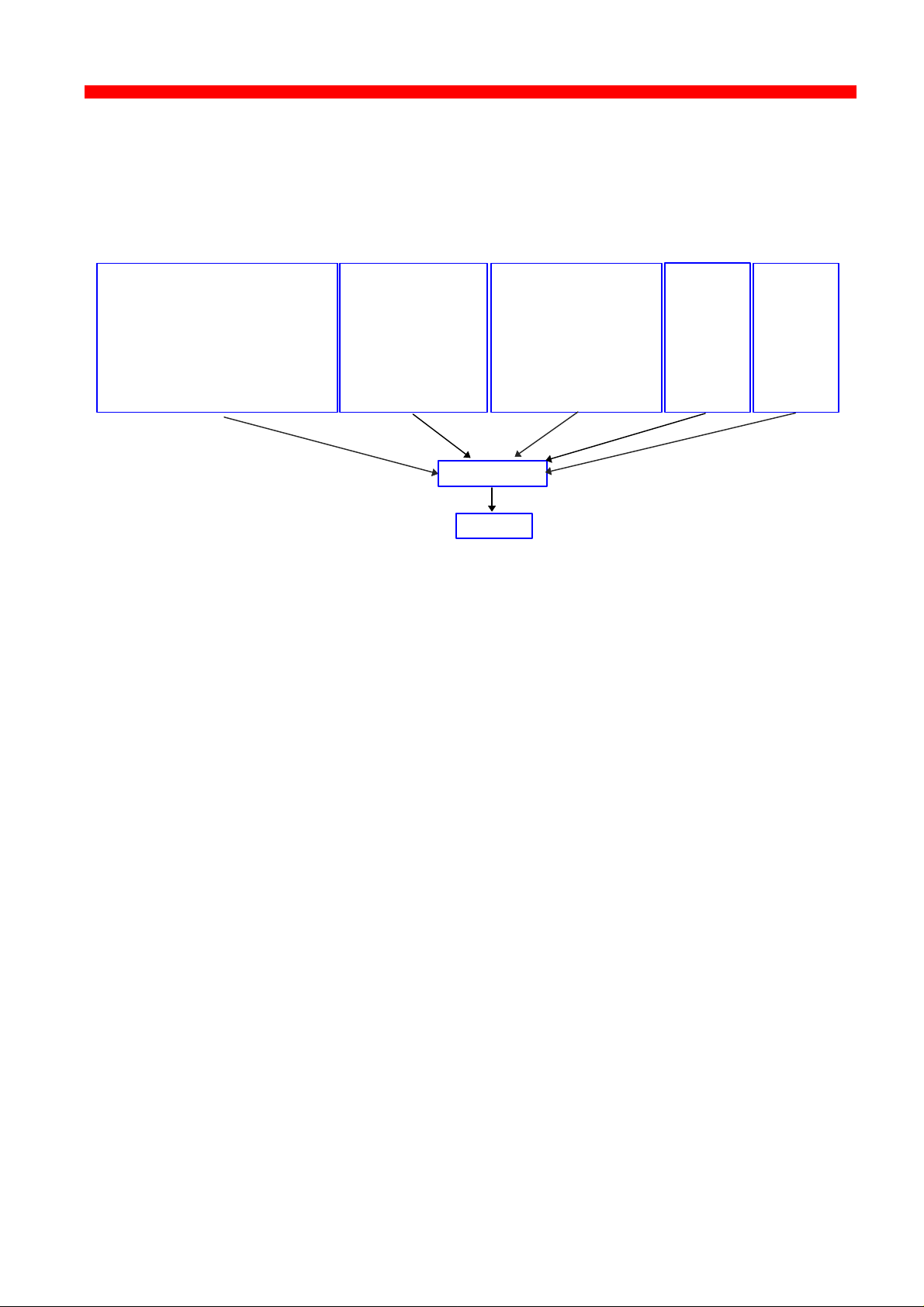
1.1.6 Illustration
The illustration in the following indicates which printer protocols are used for
the supported datastreams.
IPDS Data
- PPR (PSF/xxxx - ida ReRouter)
- ida 802.2 (idaIPPC)
- PU-LU
- LPR (DOS TCP/IP
OS/2 TCP/IP
UNIX, etc)
- ida 802.2 (idaMON)
- ENP/EPS (IPX/SPX)
- NetBios/NetBeui
SMB
ICDS Data
- PPR (PSS, ida ReRouter)
- PU/LU
1.2 The Xerox 4500 PS ETH features
The Xerox 4500 PS ETH has the following features:
Xerox 4500 PS ETH:
• FLASH prom for firmware upgrading and download of settings
SNA SCS
Data
- PU/LU
DCA SCS
Data
- LPR
• Online microcode upgrade facility
• High Performance Intel 80960 JX RISC Processor offering increased
processing speed
• Alternative setup routines for the Xerox 4500 PS ETH :
- via PSInst32
- via Web browser
- via Telnet
- via BOOTP server
For details, see the chapter 3 “Configuration“.
LAN
• Supports multiple protocols
• Supports all printers for LAN data.
• Redirects LAN native data directly to printer
12
Page 13

Introduction
Xerox 4500 PS ETH, Inst. & Operator's Guide
• Support for Novell’s embedded system’s technology (NEST) in the
form of embedded NPRINTER and embedded PSERVER.
ICDS
• Supports ICDS data streams to PCL and PostScript printers.
• ICDS printing directly from ida PSS - version 6.01 ( Xerox 4500 PS ETH)
Xerox 4500 PS ETH IPC:
• Multiple IPDS print sessions - each with own resource environment
• Download of font sets
• IBM 3812/16, 3112/16, 3912/16 and 4028 IPDS emulations
• 2 - 18 Mb internal RAM for local storage of IPDS resources
downloaded from the HOST.
• Xerox 4500 PS ETH IPC prints IPDS data directly from PSF/MVS,
PSF/400, PSF/2 and PSF/AIX.
• Xerox 4500 PS ETH IPC prints redirected IPDS data from PSF/MVS,
PSF/VM, PSF/VSE, PSF/400
Redirection can be accomplished with the following products:
PSF/2, PSF/AIX, ida ReRouter, ida IPPC
• IPDS code downloadable to Flash PROM from PC, host or PSinst32.
The IPDS code is delivered in AFPDS format and can be printed like
any other AFPDS file. Upon completion of the print job, the IPDS code
will have been upgraded.
Xerox 4500 PS ETH 3270 & 5250:
• SCS support
Xerox 4500 PS ETH with IBM 3270 support
- printing SNA via PU2 /LU1 including support for the i-data FSL
concept.
Xerox 4500 PS ETH with IBM 5250 support
- printing DCA via TCP/IP LPR/LPD
Add to this all the features supported by the Xerox 4500 PS ETH.
13
Page 14

Introduction
Xerox 4500 PS ETH, Inst. & Operator's Guide
1.3 System requirements
This section will briefly touch upon the various software requirements
needed for the environments supported by the Xerox 4500 PS ETH.
A specific description of system requirements will be provided with each
supported printing environment. You are referred to the specific chapter
describing the environment. See Table of Contents for an overview, or use
the search facility provided with the Acrobat Reader.
1.3.1 All environments:
• Ethernet LAN Attachment for 10Base2 and 10BaseT
Make sure that you have the required LAN cables to attach the Xerox 4500
PS ETH.
1.3.2 Direct AFP print - mainframe / midrange
PSF/MVS
PSF/400
PSS/MVS
PSS/VM
1.3.3 LAN based AFP print
PSF/AIX
PSF/2
1.4 Printers Supported
The Xerox 4500 PS ETH supports the following printers:
Xerox 4505
Xerox 4510
Xerox 4517
Xerox 4520
See the chapter on Installation for details of how to install the Xerox 4500
PS ETH interface into the above supported printers.
14
Page 15

Installation
Xerox 4500 PS ETH, Inst. & Operator's Guide
2. Installation of Xerox 4500 PS ETH
When unpacking the unit, record the universal MAC address on the
label attached to the rear panel of the unit.
Installation, configuration and changes to the mainframe and LAN of
the Xerox 4500 PS ETH must only be carried out by a person with
authority and knowledge of the relevant environment.
CAUTION
The interface can be damaged by static discharge. To prevent this
damage, the interface comes wrapped in an antistatic bag.
When you remove the interface from the bag and when you install it, hold
the interface by the edges only. Do not touch the components or
connections.
Do not throw away the antistatic bag. If the interface is removed from the
printer later, it should be kept in the antistatic bag.
2.1 Pre-Installation task
Prior to installing the Xerox 4500 PS ETH, you should check that
language setting (EU or US language) is correct.
Remaining switches are to be operated by support staff only.
Language setting is performed on the Dip switch bank. The DIP switch
bank sits on the interface
2.1.1 EU - US language settings
ON
ON
Dip switch number 2 is used for language setting.
OFF
OFF
1 2 3 4
1 2 3 4
You can select between EU and US language settings.
Should you need to change language setting, set dip switch number 2
as follows:
EU language setting - set the switch to OFF
US language setting - set the switch to ON
15
Page 16
Installation
Xerox 4500 PS ETH, Inst. & Operator's Guide
2.1.2 National language selection - CPGID
When you have selected either EU or US settings, you should also
check that you have the correct default codepage for your national
language.
Use the program MakeITDS - supplied with this kit - to change the
CPGID. In the following you will find guidelines for entering the CPGID
default value in the MakeITDS program.
Make a settings printout (e.g. via the test key) containing IPDS settings
and the IPDS resident codepages. The IPDS settings will state the
default codepage (CPGID - Code Page Global ID). See the example of
the IPDS settings in the following.
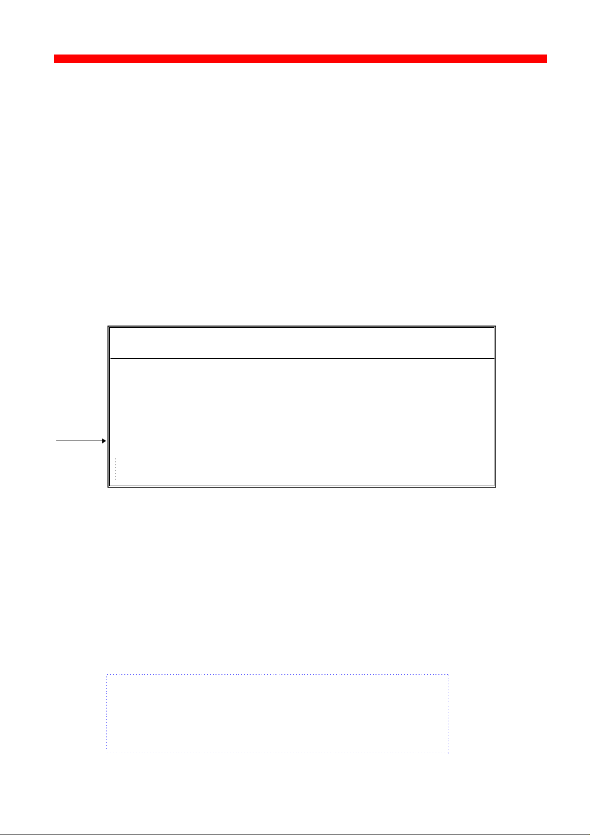
Example:
IPC - SETTINGS PRINTOUT
Firmware Version :Sxx xxx xxx
Basic Information
Installed Memory : 2 Mbytes
Installed Interface : Ethernet
IPDS Setup
IBM Emulation : 4028
Default Codepage (CPGID) : 01F4H (500)
Codepage Version : 1
In the test page containing the IPDS resident code pages you will find
the decimal number (second column) to be specified.
Appendix E contains a list of IPDS resident code pages.
In the MakeITDS (idaSetup) program, you must open the menu “IPDS
Setup” (see section 2.5.2 in the accompanying manual). In the entry
field “Default CPGID” you must enter the decimal number for the
required national language.
Example:
You wish to change to the Japanese (English) code page.
Enter decimal no. 281 in the entry field for CPGID.
16
Page 17
Installation
Xerox 4500 PS ETH, Inst. & Operator's Guide
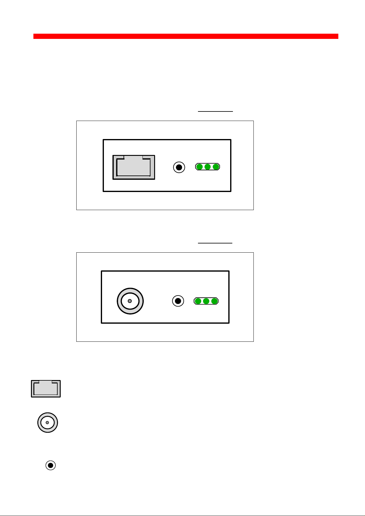
2.2 Rear panel
Below is an illustration of the rear panel of the Xerox 4500 PS ETH
followed by a short description of the panel elements.
The rear panel if you have ordered the 10 Base-T cabling type:
10 BASE-T
TEST
LAN
SES
PRT
Xerox 4500 PS ETH rear panel: 10 Base-T
TYPE NO.Xxx xxx
The rear panel if you have ordered the 10 Base-2 cabling type:
10 BASE-2
TEST
Xerox 4500 PS ETH rear panel: 10 Base-2
TYPE NO.Xxx xxx
LAN
SES
PRT
TEST
Cabling types:
10 Base-T External RJ 45 connector
10 Base-2 External BNC connector
TEST key
The test key can be used for generating a test page.
17
Page 18
Installation
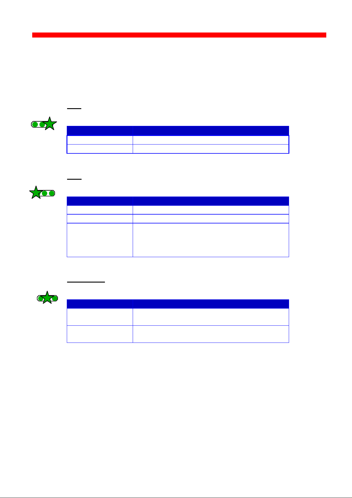
PRT
PRT
PRT
Xerox 4500 PS ETH, Inst. & Operator's Guide
LED indicators
The LEDs are used for verification purposes.
The tables below show the LED status once the Xerox 4500 PS ETH
is up and running.
PRT
LAN
SES
Indicating data to the printer.
LED Status Description
OFF No data is being sent to the printer
Blinking (async) Data is being transferred to the printer
LAN
LAN
SES
Used to indicate the LAN status
LAN
SES
LED Status Description
OFF No physical connection to LAN
ON Connection to LAN is established
Blinking Connection to LAN is established, but no boot
reply has been accepted. Refer to the chapter
“Configuration of Xerox 4500 PS ETH for
details.
SES (SION)
Indicates TCP/IP data transmission activity.
LED Status Description
OFF No data is being transmitted from the LAN
(TCP/IP)
Blinking (async) The SESSION LED blinks when data is being
processed or received (TCP/IP)
18
Page 19
Installation
Xerox 4500 PS ETH, Inst. & Operator's Guide
2.3 Installation procedure
This section describes the installation of the Xerox 4500 PS ETH
interface into one of the supported printers.
NOTE:
Before you start the installation you must power OFF.
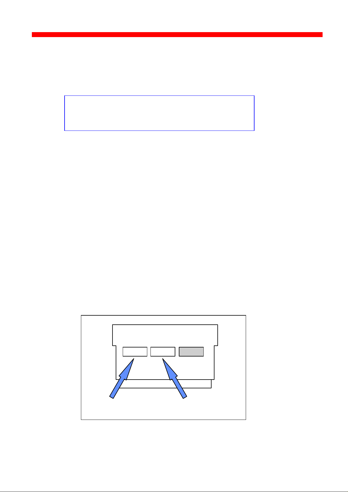
2.3.1 Installing into Xerox 4505 / 4510 printer
1. Remove the plastic cover from the rear of the printer.
2. Loosen the thumb screws.
3. Pull out the motherboard by the handle.
4. Dismantle the two blankets indicated as “ A” and “B ” in the figure below.
Save the 4 screws for later use.
5. Prior to inserting the interface in the motherboard, you are
recommended to tighten loosely one screw in the interface’s rear panel
and one in the Centronics panel.
6. Place the interface in the slot marked “ A” and place the Centronics in
the slot marked “B”.
VOID
Centronics Interface
19
Page 20

Installation
Xerox 4500 PS ETH, Inst. & Operator's Guide
7. Now fasten the two screws you loosely inserted in step 3.
8. Fasten the two remaining screws.
9. Re-insert the motherboard into the printer and fasten the
“thumbscrews”.
NOTE:
Turn power ON and generate a settings printout - pressing the test key on
the rear panel - to check that the connection to the printer has been
established.
20
Page 21
Installation
Xerox 4500 PS ETH, Inst. & Operator's Guide
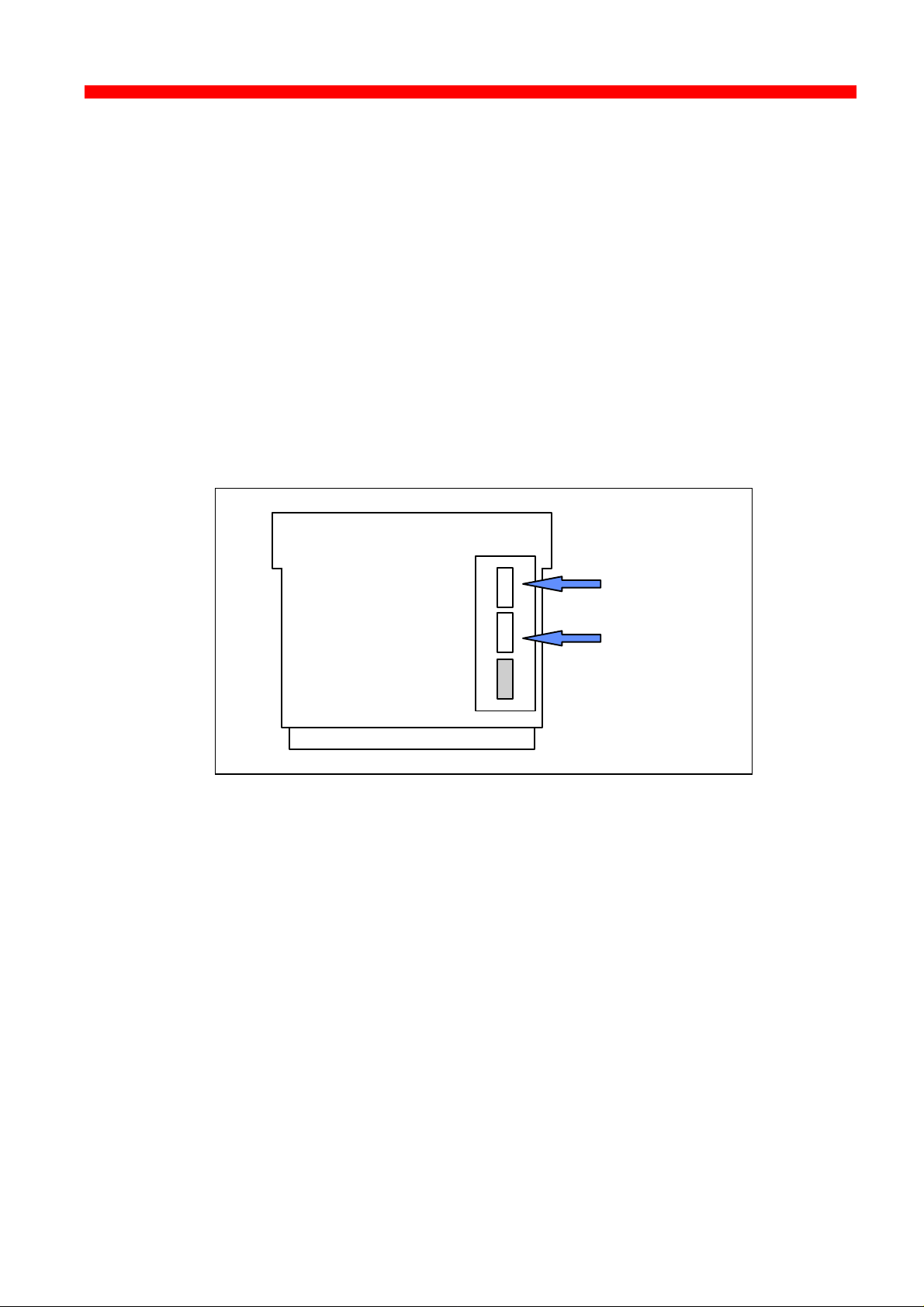
2.3.2 Installing into Xerox 4517 printer
1. Loosen the “thumbscrews”.
2. Pull out the motherboard from the printer.
3. Dismantle the two blankets and save the 4 screws for later use (see step
4).
4. Prior to inserting the interface in the motherboard, you are recommended
to tighten loosely one screw in the interface’s rear panel and one in the
Centronics panel.
5. Place the interface in the lower (middle) slot of the motherboard (marked
“A”) and place the Centronics cable in the upper slot (marked “ B”).
Centronics
Interface
VOID
6. Now fasten the two screws you loosely inserted in step 3.
7. Fasten the two remaining screws.
8. Re-insert the motherboard into the printer and fasten the
“thumbscrews”.
NOTE:
Turn power ON and generate a settings printout - pressing the test key on
the rear panel - to check that the connection to the printer has been
established.
21
Page 22
Installation
Xerox 4500 PS ETH, Inst. & Operator's Guide
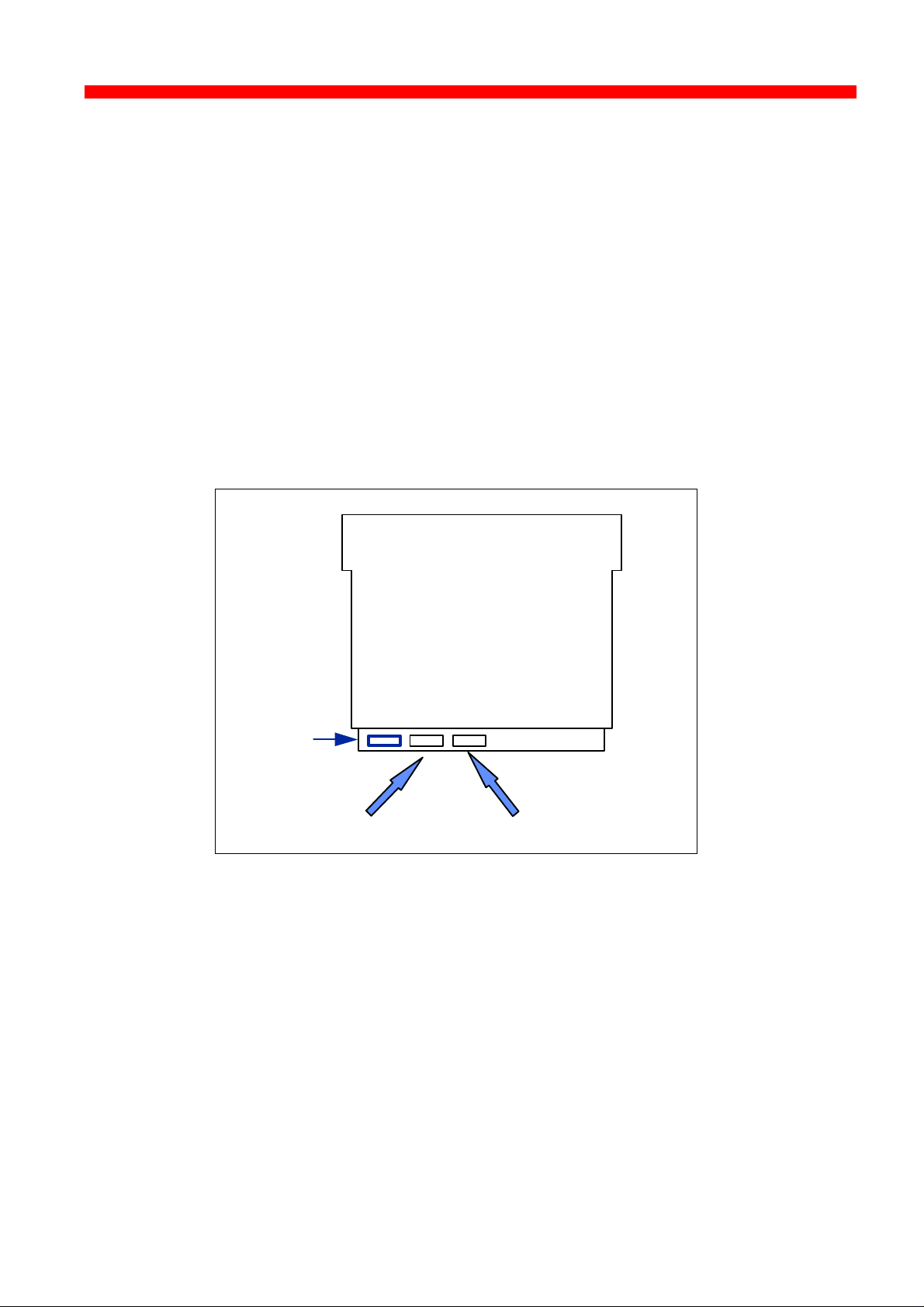
2.3.3 Installing into Xerox 4520 printer
1. Loosen the “thumbscrews”.
2. Pull out the motherboard from the printer.
3. Dismantle the two blankets and save the 4 screws for later use (see
step 4).
4. Prior to inserting the interface in the motherboard, you are
recommended to tighten loosely one screw in the interface’s rear panel
and one in the Centronics panel.
5. The interface is to be placed in the slot marked “ A” and the Centronics
in the slot marked “B”.
For optional use
Centronics Interface
6. Now fasten the two screws you loosely inserted in step 3.
7. Fasten the two remaining screws.
8. Re-insert the motherboard into the printer and fasten the
“thumbscrews”.
NOTE:
Turn power ON and generate a settings printout - pressing the test key on
the rear panel - to check that the connection to the printer has been
established.
22
Page 23

Installation
Xerox 4500 PS ETH, Inst. & Operator's Guide
2.4 Share timeout
When Xerox 4500 PS ETH operates as a print server for multiple
environments simultaneously, print corruption is avoided by excluding all
other printing as long as a print job is being printed. This is done via a
Share Timeout. The Share Timeout defines an idle time for switching
between printer sessions. As a default, the Share Timeout is set to 20
seconds, but this can be changed via the configuration file (See the
various configuration options for details ).
NOTE:
• • The Share Timeout must be set to a value which is less than the
printer’s internal printer share timer.
• • Native Share Strings:
No share string functionality is included in the Xerox 4500 PS
ETH when printing non-IPDS data, so it is up to the application to
ensure the correct printer environment.
IPDS Share Strings
To ensure that the printer environment is corre ct for IPDS printing, share
strings can be programmed using the MakeITDS Setup program.
IPDS resources downloaded to the printer are del eted on share
boundaries and are therefore downloaded to the next print job (next
usage).
2.5 Network installation
1. Switch off the printer.
2. Connect the appropriate network cable to the network port on the
PrintServer.
3. Switch on the printer.
4. Test the Xerox 4500 PS ETH (by pressing the TEST key).
When IP address has been defined:
If the TCP/IP is enabled, the LAN LED will - if BOOTP parameter set to
YES - start to flash as the Xerox 4500 PS ETH tries to contact a BOOTP
server. If no BOOTP server is available, the Xerox 4500 PS ETH will use
defaults. If valid default values are found, the LAN LED will remain lit.
The printer and network installation is now complete. For advanced
configuration, see the chapter “Configuration of Xerox 4500 PS ETH”.
23
Page 24

Installation
Xerox 4500 PS ETH, Inst. & Operator's Guide
2.6 Installing upgrade modules
This section provides installation guidelines for IPDS or FSL upgrade modules.
1. Disconnect all cables to the Xerox 4500 PS ETH.
2. Loosen the thumbscrews and pull out the interface
3. Place the upgrade module (be it IPDS or FSL) on the 4 plastic spacers
on the base module. Make sure that the pins on the connector J(x) fit
correctly.
4. Remount the interface into the printer and fasten th e 2 thumbscrews
loosened in step 2.
5. Generate a settings printout to verify the installation of the upgrade
module.
The printer and network installation is now complete. For advanced
configuration, see the chapter “Configuration”.
FIRMWARE DOWNLOAD
Firmware download when the PrintServer is equipped with a top
module can be done easily via PSinst32.
See the next section on Psinst32 for details.
24
Page 25

Configuration
Xerox 4500 PS ETH, Inst. & Operator's Guide
3. Configuration
This chapter describes how the PrintServer may be subject to a more
advanced configuration using the supported setup facilities (see below).
However, with a minimum configuration of the selected protocol, the
PrintServer is ready for operation. For details on operation based on default
settings, see below.
3.1 Introduction to configuration
When installing your PrintServer, first of all you must configure the
protocol needed in order for the system to be able to communicate with
your PrintServer.
Thus, you should ensure that the protocol you want to use for printing
has been enabled on the PrintServer. For example, if you wish to print
from Novell you need to enable the IPX/SPX protocol and configure it and
if you need to print SNA print from a host, you should enable the PU/LU
protocol and configure it. These two protocols are not enabled by default
in the product. This configuration is carried out in PSinst32 or using one
of the following tools:
⇒ Web Browser
⇒ Telnet
⇒ Configuration file
⇒ BOOTP server
See the section on “Minimum Configuration” for more details on minimum
setup via each tool.
When you are sure that you have configured the PrintServer according to
your specific needs (see this chapter: chapter 3), you will have to make
the needed definition on the system in order to be able to send print to
the PrintServer. For this you proceed to the chapters 4-17.
25
Page 26

Configuration
Xerox 4500 PS ETH, Inst. & Operator's Guide
3.1.1 Which Configuration Tool Do I Choose to Configure My PrintServer?
When delivered, the product has a MAC address but no IP address.
NOTE:
If the PrintServer is to be used for TCP/IP print, you need to
define an IP address in the PrintServer. If you wish to
configure via the Web browser or using Telnet, you need to
define an IP address in the PrintServer as well. You do this
in Psinst32 or via BOOTP.
About the IP Address
The IP address is unique in the Internet environment and consists of a
network ID and a host ID.
3.1.1.1 Psinst32
See section 3.3 for details
3.1.1.2 BOOTP Server
BOOTP contains the same options for setup as the front panel (except for
the fact that the local MAC address cannot be changed) and may also
send config files as well as download firmware. See section 3.7 for
details.
3.1.2 In General on Configuration...
The PrintServer can be subject to advanced configuration in general. This
can be done in a number of ways which will be dealt with later in this
document. The various configuration methods are:
⇒ configuration via PSinst32
⇒ configuration using Web browser
⇒ configuration via Telnet
⇒ configuration using a configuration file
⇒ configuration using BOOTP server
26
Page 27

Configuration
Xerox 4500 PS ETH, Inst. & Operator's Guide
3.2 Minimum configuration
With a minimum configuration on protocol level in addition to the default
settings, the PrintServer is ready for operation.
A minimum configuration is necessary as it is system dependent and no
default value will apply. The parameters stated in the minimum configuration
are mandatory settings for the PrintServer to become operational.
To set the minimum configuration parameters, use either the program
PSInst32 or the minimum configuration file supplied with the configuration
diskettes.
The minimum configuration only covers the most basic printing needs and a
more advanced configuration will have to be done using of the other
supported configuration methods.
PSInst32
This program is described later in this chapter.
Minimum configuration file
Modify the parameters in the minimum configuration file to suit your system
configuration. A sample configuration file is shown later in this chapter. For
download of the configuration file, see the section “Configuration using
Setup file”.
3.2.1 Mandatory settings
TCP/IP
If you wish to operate via the TCP/IP protocol, the parameters below must
be set. These are system dependent and thus the default values will not
apply. Once these parameters have been defined, printing via LPD and
PPD ports can be performed.
Mandatory parameters:
IP address
Subnet mask
Gateway
These parameters should not be chosen
at random. Contact your system
administrator for details.
IP address
To receive data on your network you need to define an IP address.
This IP address is unique in the Internet environment and consists of a
network ID and a host ID.
The IP address uses the address classes A, B and C for the various
network sizes.
27
Page 28

Configuration
Xerox 4500 PS ETH, Inst. & Operator's Guide
Subnet masks are determined by assigning ones to bits belonging to
the network ID and zeros to bits belonging to the host ID.
The subnet masks may be represented in 32-bit values or as dotted
decimal notation.
E.g.:
Class values Subnet mask
A 1-126 255.0.0.0
B 128-191 255.255.0.0
C 192-223 255.255.255.0
NETWARE - IPX/SPX
To operate via the IPX/SPX protocol thus using the Embedded Print
Server (EPS) and the Embedded Printer (ENP) , you will first have to
Enable NetWare parameter.
Subsequently you must define the following NetWare parameters:
Set mode Bindery (vs. 3.1x)
DS (vs. 4.x)
Set Preferred SERVER
Set Preferred DSTREE (valid for vs 4.x only)
Set DS name context (valid for vs 4.x only)
For EPS
- mode
- printserver
- fileserver
For ENP
- printer number
- fileserver
- printserver
SNA-SCS PRINTING - PU-LU
To operate via the PU-LU protocol, you must first set the following:
Enable PU_LU
Subsequently, define the following parameters:
Set Remote MAC (of the upstream device)
Set IDNUMBER (exchange ID number)
Set BLOCKNUMBER
28
Page 29

Configuration
Xerox 4500 PS ETH, Inst. & Operator's Guide
NetBEUI / NetBios
To operate via the NetBeui / NetBios network protocol no need for special
setup is required as printing can be performed using default values.
ida 802.2
To operate via the ida 802.2 protocol, no need for special setup is
required as printing is performed using default values.
29
Page 30

Configuration
Xerox 4500 PS ETH, Inst. & Operator's Guide
3.3 Configuration using PSinst32
The PSinst32 is a 32 bit i-data program using ida 802.2 to be run under
Windows 95 or Windows NT. The program may be used for setting up basic
parameters in the PrintServer via GUI panels. The program is designed to
complement the other PrintServer configuration tools used for more advanced
settings.
This section will limit itself to an outline description. For details you are referred
to the extensive Help provided with the program. See the following section.
Firmware download can be done using PSinst32. See the instructions
provided in section 3.3.8 “Firmware download”.
3.3.1 Program Installation Procedure
Run the installation file from the first disk and follow the instructions given
in the installation program.
NOTE:
You will be asked whether you wish to “install any
PrintServer Drivers?”. The drivers referred to here are the
various firmwares for the FSL top module.
3.3.2 Program Execution
CAUTION:
To make the PSinst32 program run correctly, you should check that
the Microsoft 32-bit DLC network protocol has been installed
correctly.
The installation procedure varies from Windows 95 to Windows NT.
See the instructions immediately below:
Windows ‘95 DLC Installation Procedure:
NOTE:
You need to have access to the CD-ROM with your
original operating system.
Click “Start” in the bottom left corner of the screen
Click “Settings”
Click “ Control Panel”
Doubleclick “Network”
Click the ”Configuration Form” and check for Microsoft 32-bit DLC
30
Page 31

Configuration
Xerox 4500 PS ETH, Inst. & Operator's Guide
- if installed then click “OK” and continue with the installation of Psinst32
- if NOT then continue below:
Click “Add”
Highlight “Protocol”
Click “Add”
Highlight “Microsoft” in the manufacturer window
Click “Have disk”
- insert the “PS configuration, disk 2/2” supplied with the Xerox 4500
PS ETH in drive a:
Click “OK”
Click “OK” and the installation begins
Click “OK” when returning to the “Network Configuration Form”
You are now prompted to insert the CD-ROM with your original operating
system mentioned in the beginning. Please follow the instructions given.
When finished, click “NO” to restart of computer
Click “Start”
Click “Run”
Click “Browse” (your floppy drive a:)
Highlight “DLC32UPD.EXE”
Click “Open”
Click “OK”
Click “Yes” to update
Click “OK” to update completely
Remove floppy disk in drive a: and restart the computer
Windows NT 4.0 DLC Installation Procedure:
NOTE:
You need to have access to the CD-ROM with your
original operating system.
Click “Start” in the bottom left corner of the screen
Click “Settings”
Click “ Control Panel”
Doubleclick “Network”
Click “Protocol” and check for “DLC Protocol”
- if already installed, click “OK” and proceed with the PSinst32 installation
- if DLC protocol is not installed then click “Add”
Highlight “DLC protocol”
Click “OK”
31
Page 32

Configuration
Xerox 4500 PS ETH, Inst. & Operator's Guide
You are prompted to insert the CD-ROM with your original operating
system mentioned in the beginning. The installation commences so
please be sure to follow the instructions given.
When finished, click “Close”.
Click “Yes” to restart the computer to activate the DLC protocol.
You can now proceed with the PSinst32 installation.
No configuration of the DLC protocol is necessary.
NOTE: - Windows 95 only -
The DLC protocol must be the Microsoft 32-bit DLC (on disk 2/2 with
configuration files) for the PSinst32 to become operative.
Executing PSinst32
To execute the PSinst32 program, you do as follows:
1. From , select “Program”, then “i-data PrintServer
Configuration Tool” and finally “PSinst32”.
32
Page 33

Configuration
Xerox 4500 PS ETH, Inst. & Operator's Guide
3.3.3 Help
You may obtain further information/Help wherever you are
in the program. The main menu and every other menu has
a Help button - click this to know more about the present
panel or to look up a search word in general.
You may also obtain context sensitive help for a particular
field or form in the program. Go to the toolbar and click
this icon.
The cursor will become the shape of a question mark. Now
you may choose to query menus from e.g. the File menu
simply by clicking it. Or you may click the Property Sheet
or Monitor Sheet to obtain further information.
33
Page 34

Configuration
Tick the entry for
configuration can
take place.
Xerox 4500 PS ETH, Inst. & Operator's Guide
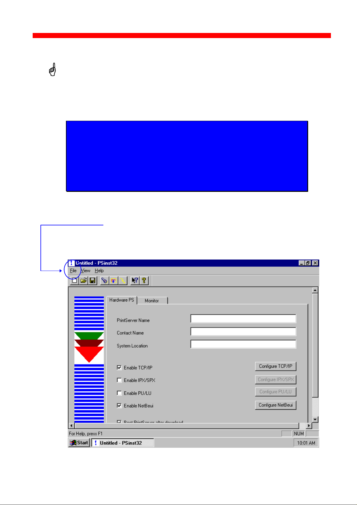
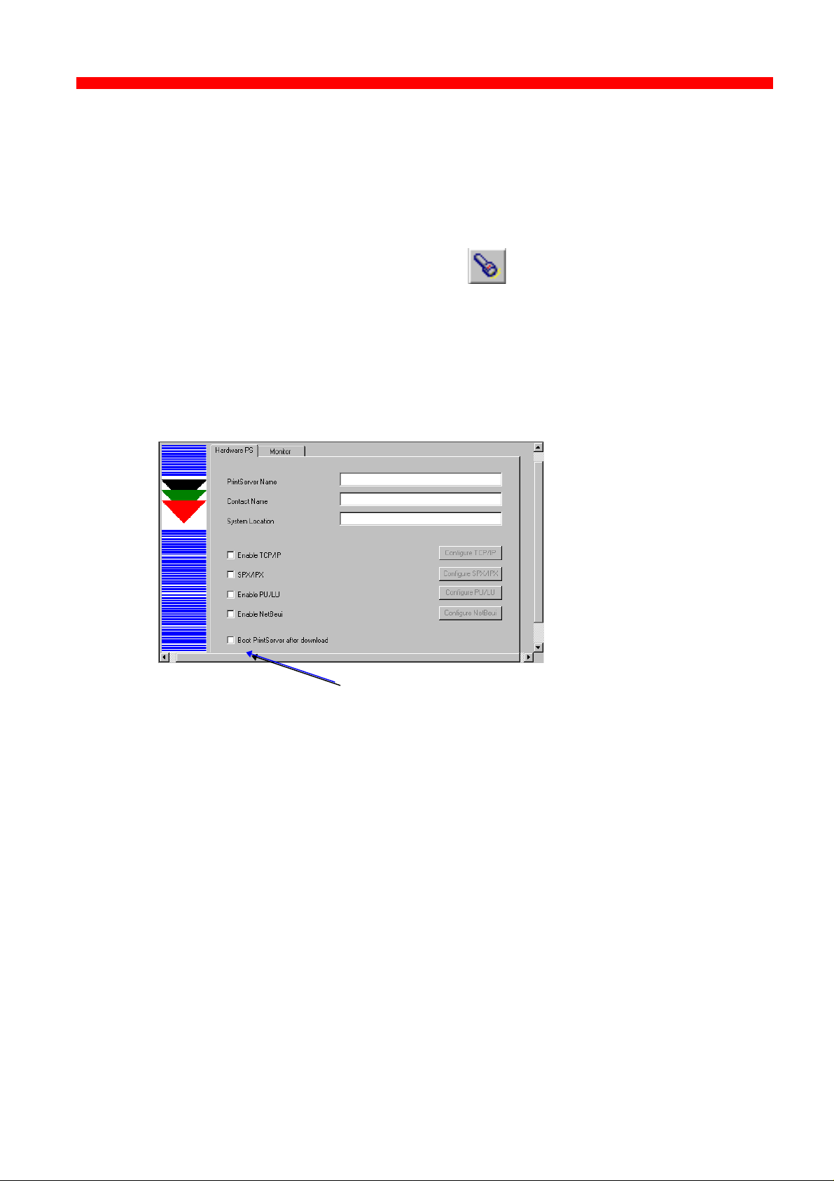
3.3.4 Main menu - Where do I start with PSinst32?
When you have installed the program, you will be met with the Main
menu. The main menu has two overall sub-category forms:
- Hardware PS Property Form
From here you enable the protocol(s) of your choice and subsequently
make the necessary configuration entries.
- “Monitor” Property Form
When you have selected a DLC download port (LAN), this menu will list
all the devices attached to the LAN.
You start your configuration in the Hardware PS Property Form, filling in
the basic information such as name and system location needed to
identify you as a user. Then proceed to the next section in this manual.
Main Window
Hardware PS
From this menu you will be able to
configure your PrintServer.
Monitoring
If you have selected LAN download
(see section 3.3.7), the “Monitor” form
will show all discovered devices by
MAC address and Name.
Names and
system location
entered by user
Protocols:
“Enable” before
Tick this entry if you wish to boot the
PrintServer after download
34
Page 35

Configuration
Set default subnet mask
SNMP - MIB II (see next
Xerox 4500 PS ETH, Inst. & Operator's Guide
3.3.5 Program setup - Configuring Your Preferred Protocol
When you have filled in the first three entries in the menu for the Hardware
Property Form:
- PrintServer name (a fully qualified domain name)
- Contact name
- Location (physical location of the unit)
.. you proceed to the selection of your preferred protocol environment
and subsequently to the configuration of it. This is necessary in order
for your system to be able to communicate with your PrintServer.
Select between:
- TCP/IP (including SNMP - MIB II)
- IPX/SPX (Netware)
- PU/LU (SNA)
- NetBIOS/NetBEUI (Windows and OS/2)
Here’s how you configure the various protocols:
3.3.5.1 Configure TCP/IP
You enable the TCP/IP protocol by clicking the check box to the immediate
left of the header “TCP/IP”. When you have enabled the protocol, you will be
able to configure the following entries:
Set default IP address.
Set default gateway
Tick this for SNMP
application.
section in this chapter)
Tick this entry if you wish
to use a BOOTP server
Seek additional
information here
NOTE: IP Address
To receive data on your network, you need to define an IP address.
This IP address is unique in the Internet environment and consists of a
network ID and a host ID.
35
Page 36

Configuration
Protocol settings
Embedded PServer see the extensive Help menu as well as overleaf.
Xerox 4500 PS ETH, Inst. & Operator's Guide
3.3.5.2 Configure SNMP
If you click the “SNMP” button in the TCP/IP menu, you will see the
following screen:
3.3.5.3 Configure SPX/IPX (NetWare - ENP)
Seek additional
information here
For indepth details on the configuration of Embedded NPrinter and
36
Seek additional
information here
Page 37

Configuration
Xerox 4500 PS ETH, Inst. & Operator's Guide
The ENP (Embedded N-Printer) submenu:
The EPS (Embedded PrintServer) submenu:
37
Page 38

Configuration
Xerox 4500 PS ETH, Inst. & Operator's Guide
3.3.5.4 Configure PU/LU (SNA)
3.3.5.5 Configure NetBEUI/NetBIOS (Windows and OS/2)
Enter remote upstream
PU MAC address of the
host - contact system
administrator for details
Seek additional
information here
NetBEUI means “NetBIOS Extended User Interface”.
Enable the Windows NetBEUI protocol from the Main menu to
enter/modify the settings for the Windows and OS/2 protocol.
Seek additional
information here
When running the NetBEUI protocol, you should note that only native data
will be processed. Attempts to generate host print (IPDS or SCS data) will not
be processed.
38
Page 39
Configuration
Xerox 4500 PS ETH, Inst. & Operator's Guide
3.3.6 Further Options - The File Menu
Before you move on to the next chapter to learn how to download your
recently defined settings (configuration of preferred protocol), let us just
sum up briefly:
Using the PSinst32 as the initial configuration tool provides you with the
options listed here:
- Configuration of network protocols:
TCP/IP, IPX/SPX - including embedded printer configuration (Novell
Netware), PU/LU (SNA), NetBEUI / NetBios (Windows and OS/2 via
SMB printer protocol)
- Network management configuration - SNMP
- Download method (via LAN) - see section 3.3.7
Now follows a description of the operations you are able to perform after
you have enabled and configured your protocol(s). So, let us take a look
at the “File” menu. The “File” menu i located in the top left corner of the
main form.
39
Page 40

Configuration
When downloading.............
You need to select a target port for download
Refresh status on existing devices (no new devices)
Discover command for new devices on the LAN
Open an existing configuration file
Switch among various adapters installed locally
Xerox 4500 PS ETH, Inst. & Operator's Guide
The File menu has the following actions available:
Below you will find guidelines to the various options listed on this menu
“Discover..”
This function will receive replies from all devices attached to the LAN
The Discover command is also available via the toolbar - look for the icon with
the flashlight on it. When you have selected LAN as the download method
(see below), the discovery function will receive a reply from the device without
any prior configuration.
“Refresh”
The Refresh command performs a sequential query for all the existing
devices on the LAN - i.e. will not see new devices. Allow some time for
this process to finish.
NOTE:
The discover function puts a heavy burden on network
traffic - so use it with care.
NOTE:
Rather use the Refresh command than the discover
operation, to ensure low network traffic if you only need to
refresh the device status
“Select Adaptor..”
Allows you to switch between different locally installed adaptors.
“Download..”
Allows you to download a file to the PrintServer
40
Page 41
Configuration
Xerox 4500 PS ETH, Inst. & Operator's Guide
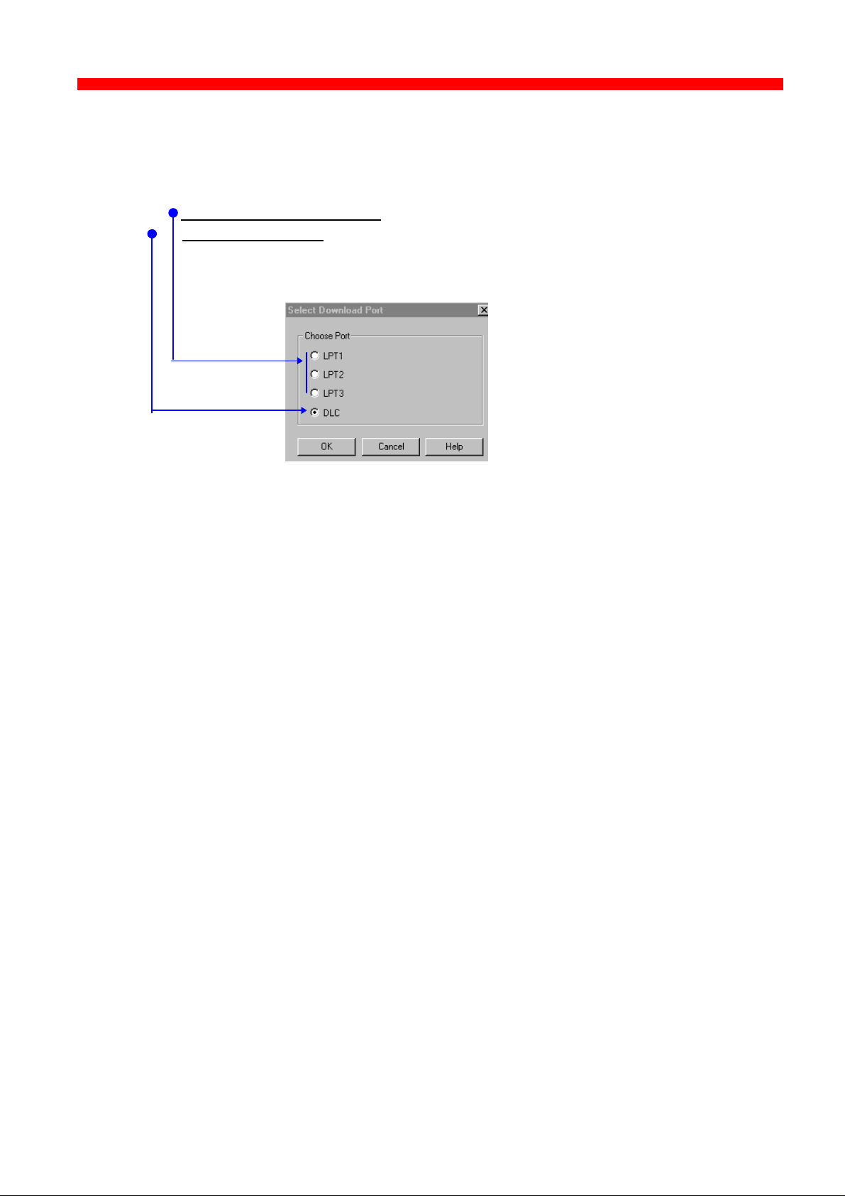
“Select Download Port..”
In order to download a configured file, you will have to select a target port.
The PSinst32 leaves you with two options:
- Download via Parallel port (not supported by this product)
Download via LAN (select DLC - NOTE: Check installation)
When using LAN as download method, you will be presented with a
dialog containing a list of discovered devices. The devices are
discovered by MAC address. See the “Broadcasting” section 3.3.9.
41
Page 42

Configuration
Xerox 4500 PS ETH, Inst. & Operator's Guide
3.3.7 End of Configuration - Downloading Settings to the PrintServer
When you have completed the configuration of the selected protocol
environment(s), you must download the new settings to the selected target port.
This download target port must be via the LAN.
“Select DLC download port”
Choose the “Select Download Port” option from the “File” menu in the top
left corner of the screen. The following form will be displayed:
- Download via LAN - select DLC (NOTE: Check installation)
When using LAN as download method, you will be presented with a
dialog containing a list of discovered devices. The devices are
discovered by MAC address. See the “Broadcasting” section 3.3.9.
Next, select the menu “Download” in the “File” menu which you will find in the
top left corner of your main menu.
Now the Monitor form will appear listing all available devices on the
network.
42
Page 43
Configuration
Xerox 4500 PS ETH, Inst. & Operator's Guide
NOTE:
If the Monitor form does not appear by itself, click the
Monitor form and select the “Discover” function to contact
your device. The “Discover” function will perform a
broadcast on your network contacting and subsequently
listing all available devices. You can activate the
“Discover” function from the “File” menu (see illustration
above) or by clicking this icon:
When your device is listed in the Monitor form, highlight the device and
click “OK” to download your new settings to it.
Boot PrintServer after download
You will find this option in the main menu “Hardware PS” Form.
If the new settings you have just downloaded differ from the current
settings - and no error situations have occured - , the PrintServer will
immediately be booted when ticking the field “ Boot PrintServer............” .
The display of warning messages does not prevent the PrintServer from
being booted.
43
Page 44

Configuration
Xerox 4500 PS ETH, Inst. & Operator's Guide
3.3.8 Firmware download
It is possible to download firmware via PSinst32 by activating the menu
“Download From..” from the “File” menu. When activated you will see this
screen:
As a default PSinst32 will promt for download of PrintServer configuration
files but other files can be downloaded clicking “Files of type”:
- PS Configuration Files
- MakeITDS Configuration Files
- IPDS Top Firmware
- FSL Top Firmware
- IPDS Fontset
- Base Code
- All files
In the following you will see how to download firmware in the shape of
PrintServer drivers when the PrintServer is equipped with a top module for
IBM 3270 or IBM 5250 environment printing.
Example of downloading firmware for PrintServer drivers
When the PrintServer is equipped with a top module for printing in IBM
3270 or 5250 environments, the driver can be downloaded as follows:
1. In the above form click “Files of Type”
2. Select “FSL Top Firmware”
3. On the screen you will see a number of drivers.
44
Page 45

Configuration
(Mainframe)
(Mainframe)
(Mainframe)
Xerox 4500 PS ETH, Inst. & Operator's Guide
PCL/SCS
PCL/DCA (AS/400)
3270 /SCS
XES/DCA (AS/400)
XES/SCS
150/SCS (AS/400)
4. Highlight the driver you wish to use and click “ Open”.
5. Now the Monitor Form screen with the attached device s will appear.
In this menu, you highlight the device to where you wish to download
the PrintServer driver.
6. When selected, click “ OK” and the firmware is downloaded to the
device.
3.3.9 Broadcasting
170/SCS (Mainframe)
One of the strong features of PSinst32 is the ability to detect and configure
devices via the LAN. When the DLC port has been selected as download
port, it is possible to detect devices even before an IP address has been
associated. This kind of detection is called broadcasting. A broadcast
message is issued through all bridges on the LAN. All associated devices
will be able to recognize this message, and will return an identification
message. The monitor sheet displays all devices which respond to the
broadcast message.
NOTE:
Since broadcasting puts a heavy burden on the network, it
should be limited to a minimum.
If you only need to update the status of the devices
attached to the LAN, you are recommended to use the
“Refresh” command instead of the “Discover” to lower
network burden.
45
Page 46

Configuration
Xerox 4500 PS ETH, Inst. & Operator's Guide
The Monitor menu screen consists of the following information fields:
- MAC address:
This is the MAC address of the device. When activating the discover (or
Refresh) command, the device will sort the devices according to MAC
address and Name. New configured devices will be displayed at the top.
- Name:
This is the name (if any) the user has attached to the PrintServer
- Status:
The status menu will show the present status of the output ports on the
device. For detailed status information, double-click on a specific device.
46
Page 47

Configuration
Xerox 4500 PS ETH, Inst. & Operator's Guide
3.4 Configuration using Web Browser
With a standard Web Browser, the PrintServer
supports configuration and status tasks. This
section provides an outline description of the
settings to be performed using the Web browser.
3.4.1 Requirements
A standard Web browser with Frame support.
If you use a no-frame browser (e.g. Microsoft Explorer), certain functions
will not be supported.
3.4.2 Access to ida HTML configuration
A configuration session requires the log on to the PrintServer entering
your IP address.
At the URL prompt type:
http:// < PrintServer IP address>
3.4.2.1 IP address
The IP address may be defined using one of these configuration tools:
- PSinst32
- Setup file
- BOOTP
- Via the Front Panel
These configuration methods are described elsewhere in this manual. For
details on the IP address, you are to consult your system manager.
When you have executed the URL command, you will be presented with
the following PrintServer HTML configuration panel:
47
Page 48

Configuration
***
Xerox 4500 PS ETH, Inst. & Operator's Guide
3.4.2.2 Password
You will now be prompted for a password. From the factory, the password
is “adm”.
Once the <PRINTSERVER> has accepted the default password, you are
ready to make the desired configuration / view status on your PrintServer.
NOTE:
• You are recommended to change this password. See the menu
“Change Password” for details.
• All settings must be confirmed using the menu “ Save Configuration” to
become effective.
48
Page 49

Configuration
PrintServer
PrintServer
Xerox 4500 PS ETH, Inst. & Operator's Guide
3.4.3 Overview
This contains an outline description of the PrintServer and other printing options.
Click this to enter the main configuration menu - see below for details.
If you are connected to the Internet, you will get direct access to the i-data
Homepage clicking this button.
Should the session time out, you can re-establish activating this button.
When you have made the necessary settings, you terminate the session via
this menu.
3.4.4 Configuration chart
This is a chart of the configuration and status options supported with the PrintServer
Configure
Status
- Configure General Parameters
- Configure PrintServer Parameters
- Configure TCP/IP
- Configure IPX/SPX
- Configure ida 802.2
- Configure PU/LU
- Configure NetBios
- Save Configuration
- Restore Configuration
- Restore Factory Def.
- Change Password
- Reboot PrintServer
- Status LAN Interface
- Status TCP/IP Protocol
- Status IPX/SPX Protocol
- Status PU/LU Protocol
- Status SNMP Agent
- Status Printer
- Error Log
49
Page 50

Configuration
Xerox 4500 PS ETH, Inst. & Operator's Guide
3.4.5 Main Menu
When you click the Main Menu, you will be presented with the two main
tasks in the PrintServer HTML configuration program:
3.4.6 Configure PrintServer
50
Page 51

Configuration
Xerox 4500 PS ETH, Inst. & Operator's Guide
When you have made all the necessary configurations via this entry
menu, click the menu at the very bottom to the right - Previous Menu
(not visible on this screen).
Remember to save via “Save Configuration” for the changes to
become effective
3.4.7 PrintServer Status Menu
The status menus provide you with various product information depending
on which panel you select.
You can update the information by clicking the menu “ Refresh”.
NOTE: Some browsers (no-Frame) do not support the Refresh function.
51
Page 52

Configuration
Xerox 4500 PS ETH, Inst. & Operator's Guide
3.5 Configuration using Telnet
The Telnet support (Terminal Emulation
Protocol) offers yet another way of configuring
and monitoring the PrintServer. For this you will
need the emulations VT 100 and NVT. Telnet is
ida PrintServer x3 MIO
A)
Configure PrintServer
B)
Status PrintServer
X)
Logout
EnterSelection
083.xxx
a standard TCP/IP application permitting
access from TCP/IP attached host systems.
NOTE:
As Telnet requires NVT and VT100 terminal
emulations, Telnet configuration support is not valid when running VM and
MVS.
Due to restrictions in the AS/400 Telnet implementation, the following
information should be considered:
“If you do not want the characters that are being typed to be displayed, the
function key associated with the “Hide” function should be pressed (F6 on the
default keyboard map). This function should be used when typing a password.
If you want the characters that have been typed to be sent to the remote
system for processing without pressing the Enter key, you should press the
function key associated with the “SENDWOCR” function (F11 on the default
keyboard map).”
(source: IBM: Network in Red Books, SK 2T-6022).
To establish a Telnet session with a PrintServer interface you need to
program the PrintServer with an IP address. This address may also be
configured via one of the many other configuration methods available (as
described in this chapter).
EXAMPLE:
To start a Telnet session on a Telnet capable host, type the following:
Telnet 192.0.110.1.
where
192.0.110.1. is the IP address of the PrintServer.
(For IP address details contact your system administrator)
When a Telnet session has been established, the PrintServer will prompt
the host for a userid and password.
The userid will be adm and the password will initially be defined as adm
You are recommended to change this initial password. To change the
default password, see section 3.5.5 .
52
Page 53

Configuration
Xerox 4500 PS ETH, Inst. & Operator's Guide
Once the PrintServer has accepted the default password, the following
screen will appear. For details on the main menu, see section 3.5.1
<PrintServer> Main Menu 0xx.xxx
A) Configure PrintServer
B) Status PrintServer
X) Logout
EnterSelection
Navigation keys
When configuring using the Telnet, the following navigation keys will be
used:
Selecting menu fields Key value (e.g. type A)
Toggling between entry options
Space bar
Selecting a given value ENTER key
Return to previous level/exit X
Other menu keys will be ignored for navigation purposes.
Validation will be performed in the various Telnet menus to make sure that
only valid field updates are performed. An error message will appear if an
entry is made incorrectly.
Important:
The new settings will only take effect when you select the menu
“Save Configuration” and then “Reboot PrintServer”.
53
Page 54

Configuration
section 3.5.2
Xerox 4500 PS ETH, Inst. & Operator's Guide
3.5.1 Menu Structure
This section provides an outline description of how to configure and
monitor the PrintServer using Telnet.
Main Menu
<PrintServer> Main Menu 0xx.xxx
A) Configure PrintServer
B) Status PrintServer
X) Logout
EnterSelection
If you wish to configure the PrintServer, type A at the selection prompt.
3.5.2 Configuring PrintServer
Configure PrintServer - Submenu
<PrintServer> Configuration Menu 0xx.xxx
A) Configure General Parameters
B) Configure Sessions
section 3.5.11
section 3.5.3
section 3.5.4
C) Save Configuration
D) Restore Configuration
E) Restore Factory defaults
F) Change Password
R) Reboot PrintServer
T) Trace Destination
X) Return to previous menu
EnterSelection
section 3.5.6
section 3.5.7
section 3.5.8.
section 3.5.5
section 3.5.9.
section 3.5.10.
54
Page 55
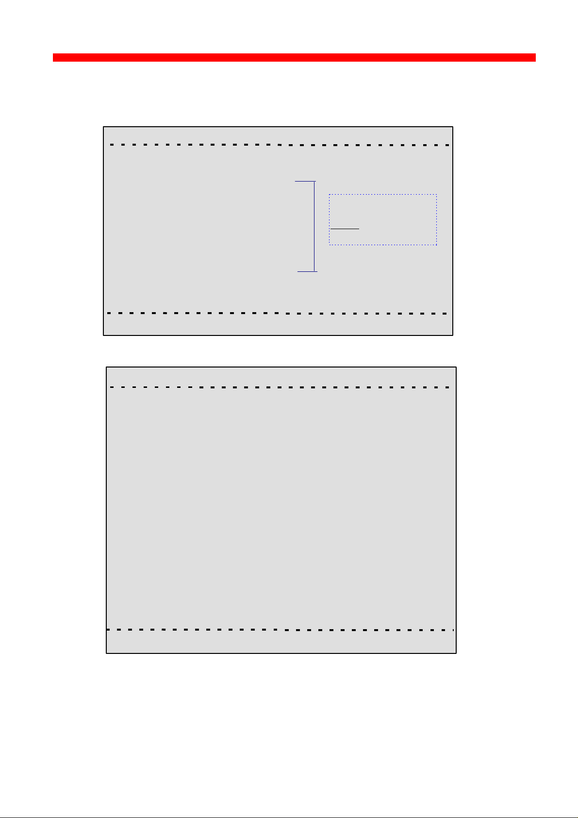
Configuration
the protocol first.
Xerox 4500 PS ETH, Inst. & Operator's Guide
3.5.3 General Parameters Menu
Type A to enter the submenu for further configuration of the PrintServer.
<PrintServer> Configure PrintServer 0xx.xxx
A) Configure PrintServer Parameters
B) Configure TCP/IP
C) Configure IPX/SPX
D) Configure ida 802.2
E) Configure PU/LU
F) Configure NetBios
F) Configure SNMP
X) Return to previous menu
NOTE:
Remember to
enable
Press A.
EnterSelection
PrintServer Configuration
<PrintServer> Configure PrintServer 0xx.xxx
A) PS Name
B) Location
C) ContactPerson
D) Local MAC address...........: E) Early Token Release.........:
F) MAC address enabled.......: G) Broadcast Type
H) TCP/IP enabled..................: I) IPX/SPX enabled...............:
J) PU/LU enabled...................: K) NetBeui enabled...............:
L) Share Timeout...................:
M)IRQ Timeout.......................:
N) Hold Timeout.....................:
O) BOOT enabled...................:
X) Save and Return Z) Return without saving
Enter Selection
55
Page 56

Configuration
Xerox 4500 PS ETH, Inst. & Operator's Guide
Enter Selection
To make an entry for the local MAC address, type A. This will place you in
the prompt for the local MAC address. If the entry is incorrect, you will
receive an error message.
To return to the “Enter Selection” prompt, press Enter.
For action fields other than text entries (e.g. MAC Address) use the space
bar to toggle the entry options.
TCP/IP Configuration
Remember to set “TCP/IP enabled” to YES.
<PrintServer> Configure TCP/IP 0xx.xxx
A) HostName..............................:
B) Use BOOTP Server...............:
C) TCP MSS...............................:
D) TCP Window.........................:
E) Default IP address...............:
F) Default SubNet Mask..........:
G) Default Gateway Address...:
H) Microcode Filename...........:
You may use this entry field to
write specific information on e.g.
target printer:
NET1stFloor or John Doe’s lpt.
A maximum of 15 characters is
recommended for host name
X) Save and Return Z) Return without saving
EnterSelection
56
Page 57

Configuration
Xerox 4500 PS ETH, Inst. & Operator's Guide
IPX/SPX Configuration
Remember to set “IPX/SPX enabled” to YES.
Use the space bar to toggle through the options
<PrintServer> Configure IPX/SPX 0xx.xxx
Frames:1) 802.2:YES 2) SNAP: YES
A) NCP mode........................:
B) NCP preferred Server......:
C) NCP preferred DStree.....:
D) NCP DSname context.....:
E) EPS mode........................:
F) EPS PrintServer..............:
G) EPS FileServer................:
H) EPS Bindery Poll Tim.....:
I) EPS Password.................:
X) Save and Return Z) Return without saving
EnterSelection
NOTES:
Bindery Poll Time
If version 4.x (DS) is selected as NCP mode, the entry “Bindery Poll Time”
will NOT appear in the test printout. It will, however, be maintained as an
entry in Telnet, regardless of NCP mode.
EPS Password
This password must be a match of the NetWare PServer password.
When printing you should check the connection to the PServer viewing
the NetWare menu “Active Connections”.
ida 802.2 Configuration
<PrintServer> Configure ida 802.2 0xx.xxx
A) Alias Name....................:
X) Save and Return Z) Return without saving
Enter Selection:
57
Page 58

Configuration
Xerox 4500 PS ETH, Inst. & Operator's Guide
PU/LU Configuration
Remember to set “PU/LU enabled” to YES.
<PrintServer> Configure PU/LU 0xx.xxx
A) Blocknumber.................: 05D
B) ID number......................: 00000
C) Remote MAC address...:
D) Local SAP......................:
E) Remote SAP..................: 04
X) Save and Return Z) Return without saving
Upstream PU
MAC address
Enter Selection:
NetBios Configuration
Remember to set “NetBeui enabled” to YES.
<PrintServer> Configure NetBios 0xx.xxx
A) Servername.................:
B) Work Group.................: WORKGROUP
X) Save and Return Z) Return without saving
Enter Selection:
58
Page 59
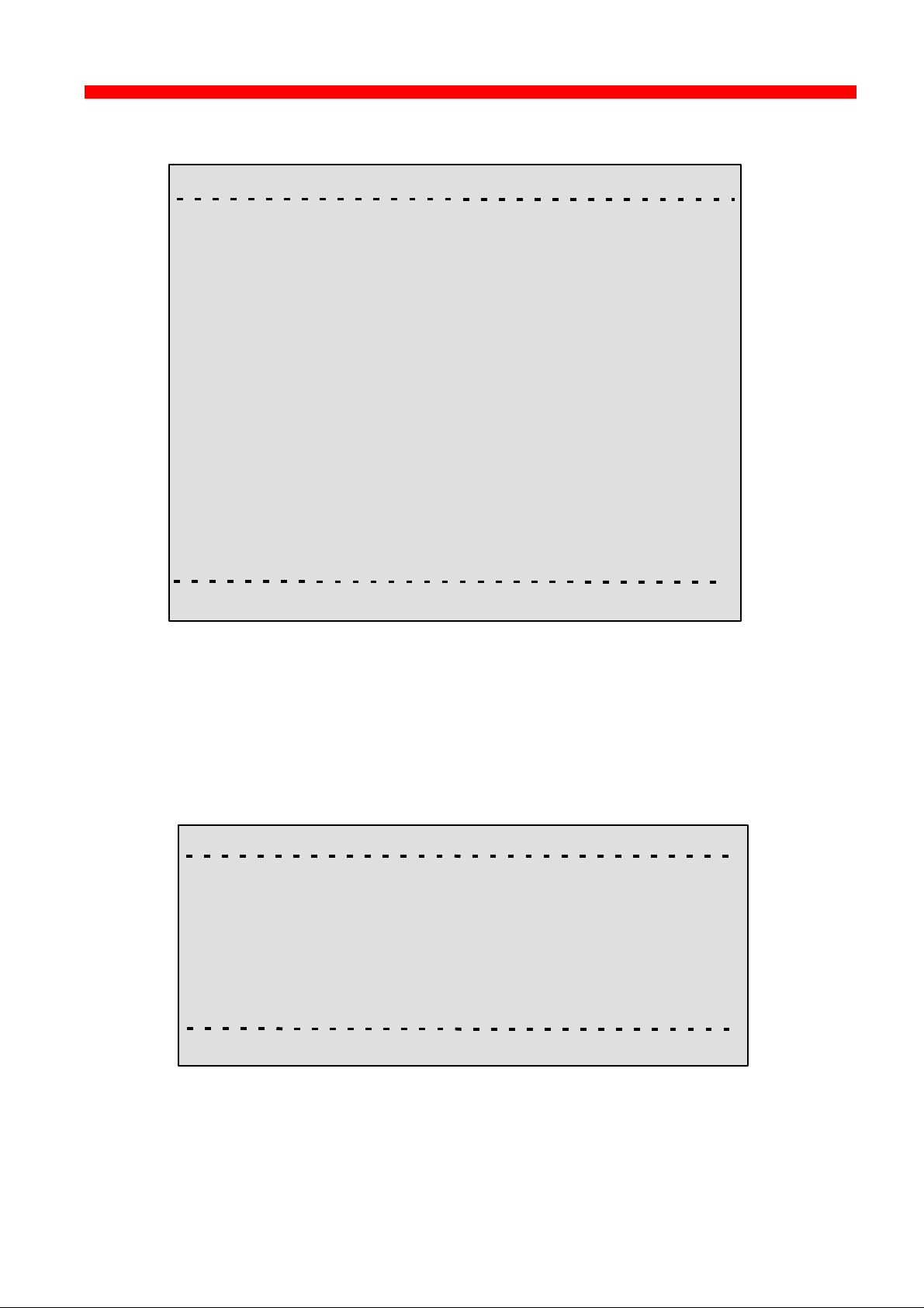
Configuration
Xerox 4500 PS ETH, Inst. & Operator's Guide
SNMP Configuration
<PrintServer> Configure SNMP agent 0xx.xxx
SNMP Trap Destinations Authentication Traps:
No. Index Community Name IP Address
-
-
-
SNMP Manager Access Authorization
No. Index Community Name Access Network Address Mask
-
-
-
A) Add D) Delete C) Change AuthTrap X) Return Enter Action
For adding an SNMP Trap parameter or configuring the access
parameters press A for ADD.
You can now select between T)rap or A)uthorize parameters.
Selecting Trap will present the following screen:
<PrintServer> Configure SNMP Trap Parameters 0xx.xxx
A) Destination IP Address ................................:
B) Destination Community Name.....................:
X) Save and Return
Enter Selection
59
Page 60

Configuration
Xerox 4500 PS ETH, Inst. & Operator's Guide
Selecting Authorize will present the following screen:
<PrintServer> Configure SNMP Access Parameters 0xx.xxx
A) Community Name.....................................:
B) Manager IP Address.................................:
C) IP Address Mask.......................................:
D) Manager Access Type..............................:
X) Save and Return
Enter Selection
60
Page 61

Configuration
Xerox 4500 PS ETH, Inst. & Operator's Guide
3.5.4 Configure Sessions
In the sub-menu for the “Configure PrintServer”, select “Configure
Sessions” typing B at the selection prompts. You will see the following
screen:
“+” Means
that Trace
has been
activated
Means
session is
active
<PrintServer> Configure sessions 0xx.xxx
No. Enabled Session Description
1 YES* +PPD 5001 --> IPDS DATA --> PRINTER
2 YES* +PPD 5002 --> IPDS DATA --> PRINTER
3 YES* +LPD q: LPDPRT1 --> PRINTER
4 YES* +LPD q: LPDPRT1ACR --> PRINTER
5 YES* +ENP PNO:0 -->PRINTER
6 YES* +SNA Print --> SCS data --> PRINTER
7 ___ _________________________________
8 ___ _________________________________
9 ___ _________________________________
10 ___ _________________________________
11 ___ _________________________________
12 ___ _________________________________
13 ___ _________________________________
14 ___ _________________________________
T) Trace U) Untrace S) Status D) Delete E) Edit X) Return Enter action:
To edit a specific sub-menu, type E (Edit) and the
required parameter to modify and then press <ENTER>.
3.5.5 Change Password
In the sub-menu for the “Configure PrintServer” select “Change
Password” by typing F at the selection prompts.
You are now prompted for the old password.
<PrintServer> Change Password 0xx.xxx
Old Password: ******
When entered, you will be prompted for a new password.
Finally, the new password must be re-entered to be confirmed by the
system.
61
Page 62

Configuration
Xerox 4500 PS ETH, Inst. & Operator's Guide
NOTE:
Only the password for the current session can be changed.
If an invalid password is entered, the previous menu level
is displayed.
3.5.6 Save Configuration
NOTE:
When you have made new settings or changed existing, you must
save the settings with this menu. Then reboot the printserver (see
section “Reboot PrintServer below). If you fail to do this the
new/modified settings will be lost when the printer is turned off.
In the sub-menu for the “Configure PrintServer” select “Save
Configuration” by typing C at the selection prompts. You will see the
following screen:
<PrintServer> Save Settings 0xx.xxx
Saving current settings will overwrite default settings.
Enter “YES” to Save or “NO” to return without saving.
Save current Settings to Flash?
3.5.7 Restore Configuration
In the sub-menu for the “Configure PrintServer” select “Restore
Configuration” by typing D at the selection prompts. Follow the
instructions on the screen.
3.5.8 Restore Factory Default
In the sub-menu for the “Configure PrintServer” select “Restore Factory
Default” by typing E at the selection prompts. Follow the instructions on
the screen.
62
Page 63

Configuration
Xerox 4500 PS ETH, Inst. & Operator's Guide
3.5.9 Reboot PrintServer
In the sub-menu for the “Configure PrintServer” select “Reboot
PrintServer” by typing R at the selection prompts. Follow the instructions
on the screen.
3.5.10 Trace destination
Type T at the selection prompt to enable the trace facility.
<PrintServer> Trace destination parameters 0xx.xxx
A) FTP Host Name..............:
B) User Name......................:
C) Password........................:
D) File Name........................:
S) Start Trace
T) Stop Trace
X) Return
not tracing !
indicates the trace status
Type e.g. A (FTP Host Name) to be prompted for making entries to the
trace destination parameters.
Press Enter when you have made your entries.
NOTE:
By default all sessions have trace enabled
63
Page 64

Configuration
Xerox 4500 PS ETH, Inst. & Operator's Guide
3.5.11 Status PrintServer
From the main menu select the menu “Status PrintServer” by typing B at
the selection prompt. This will lead to the following screen.
<PrintServer> Status Menu 0xx.xxx
A) Status LAN interface
B) Status TCP/IP
C) Status IPX/SPX
D) Status PU/LU
E) Status NetBios
F) Status Printer
G) Status SNMP Agent
L) List Last Error Log
X) Return to previous menu
Enter Selection:
Enter a selection to view the current status.
64
Page 65

Configuration
Xerox 4500 PS ETH, Inst. & Operator's Guide
3.6 Configuration using Setup File
Only modify or change the settings via the configuration file if strictly necessary.
Otherwise, you are recommended to use one of the other configuration tools (see above)
The sample configuration files supplied with the PrintServer may be used to
configure or re-configure the product. The files may be sent directly via the
LAN. The protocols used may be programmed in the PrintServer.
Setup File Identifier
The configuration file must be started with the following string:
&&??##N1,0#
and be terminated with this string.
&&??<space>
These strings are used for identifying the setup file when being
downloaded. They must not in any way be altered.
You are recommended to stop all printer sessions before the downloading of
(new) configuration settings as active print sessions may be interrupted.
Default settings for the PrintServer are supplied with each unit.
65
Page 66

Configuration
Xerox 4500 PS ETH, Inst. & Operator's Guide
3.6.1 Sample minimum configuration file
&&??##N1,0# : Start of file - Don’t remove this!
Short configuration for a PrintServer
(This is an example. Please modify the parameters to match your configuration).
00XXX00X
**********************************************************************
IDAPS
**********************************************************************
BEGIN_CONFIGURATION IDAPS
ENABLE_TCPIP YES ; ENABLE TCP/IP protocol
ENABLE_802_2 YES ; ENABLE 802.2 protocol
ENABLE_NETWARE NO ; ENABLE Netware protocol
ENABLE_PU_LU NO ; DISABLE PU/LU protocol
ENABLE_NETBEUI YES ; ENABLE NetBEUI protocol
BOOT YES ; Reboot PS if conf.has changed
**********************************************************************
TCPIP
**********************************************************************
BEGIN_CONFIGURATION TCPIP
BOOT YES ; BOOT from BOOTP server
DEFAULT_IP 192.0.0.1 ; IP addr. if not booted by BOOTP
DEFAULT_SM 255.255.255.0; Subnet Mask if not booted by BOOTP
DEFAULT_GW 192.0.0.0 ; Gateway addr. if not booted by BOOTP
END
;****************************************************************************
P U
;**********************************************************************
BEGIN_CONFIGURATION PU
; BLOCKNUMBER 05D ; Fill in your Block number
; IDNUMBER 00000 ; Fill in your ID number
; REMOTE_MAC 400000000000 ; Fill in HOST / GW MAC address.
END
;*********************************************************************
NETWARE
;*********************************************************************
BEGIN_CONFIGURATION NETWARE
LSL_FRAME_802_2 YES ; Use 802.2 protocol
LSL_FRAME_802_SNAP NO ; Disable SNAP protocol
NCP_MODE DS ; BINDERY or DS, match server
NCP_PREFERRED_SERVER XXXXXXXXX ; Name of fileserver
NCP_PREFERRED_DSTREE XXXXXXXXX ; NetWare 4.x only
NCP_DSNAME_CONTEXT XXXXXXXXX ; NetWare 4.x only
**********************************************************************
802.2
**********************************************************************
BEGIN_CONFIGURATION 802_2
ALIASNAME XXXXXXXXX ; Shown in the idaPMUTL window
**********************************************************************
IDA802_2 ID 1
**********************************************************************
BEGIN_CONFIGURATION 802_2 1
INSTREAM_802_2 NATIVE ; Transparent print
**********************************************************************
ENP ID 1
**********************************************************************
BEGIN_CONFIGURATION ENP 1
PRINTERNUMBER XXXXXXXXX ; Capture printer 0 on Novell server
FILESERVER XXXXXXXXX ; Name of fileserver
PRINTSERVER XXXXXXXXX ; Name of printserver
MODE XXXXXXXXX ; BINDERY or DS, match server
66
../continued
Page 67

Configuration
Xerox 4500 PS ETH, Inst. & Operator's Guide
*********************************************************************
********************************************************************
BEGIN_CONFIGURATION ENP 2
PRINTERNUMBER XXXXXXXXX ; Capture printer 1 on Novell server
FILESERVER XXXXXXXXX ; Name of fileserver
PRINTSERVER XXXXXXXXX ; Name of printserver
MODE XXXXXXXXX ; BINDERY or DS, match server
**********************************************************************
**********************************************************************
BEGIN_CONFIGURATION NETBIOS
SERVE_NAME XXXXXXXXX ; NetBIOS server name
WORKGROUP WORKGROUP ; Workgroup for the PrintServer
END
&&??
ENP ID 2
NETBIOS
67
Page 68

Configuration
Xerox 4500 PS ETH, Inst. & Operator's Guide
3.6.2 Advanced configuration
In this section you will find examples of how to configure the various setup
file parameters. The purpose of these examples is to provide you with
simple guidelines for configuration using the setup file.
The chart below provides an overview of the various configuration options.
GROUP PARAMETERS
IPDS
PU/LU
SNA ENP 802.2
SCS
TCP/IP
LPD
ICDS IPDS
NetBeui
PPD
NetBios /
NETWARE
IDA
802.2
SCS
PRINTER
68
Page 69

Configuration
Xerox 4500 PS ETH, Inst. & Operator's Guide
Enabling IDAPS
Here the following group parameters are enabled / disabled.
If a group parameter is following the setup definitions for the various sessions,
e.g. IPDS input for a session, these must be configured. See the following
sections.
BEGIN_CONFIGURATION IDAPS
LOCAL_MAC 4XXXXXXXXXXXX
SEL_MAC UNIVERSAL
EARLY_TOKEN NO
ENABLE_TCPIP YES
ENABLE_NETWARE NO
ENABLE_802_2 YES
ENABLE_NETBIOS YES
ENABLE_PU_LU NO
BOOT YES
SHARETIMEOUT 20
HOLDTIMEOUT 600
IRQTIMEOUT 60
END
Defining PU_LU
NOTE: The PU_LU session requires the installation of an FSL or IPDS
To enable a PU_LU session (SNA), the following keywords are used. The
keywords must match the values configured in the chapter ”SCS Printing
Using SNA”.
BEGIN_CONFIGURATION PU
BLOCKNUMBER 05D
IDNUMBER 0 (set exchange ID number)
REMOTE_MAC 000 (set the MAC address of the upstream device)
LOCAL_SAP 4
REMOTE_SAP 4
END
Define SNA
To define a SNA session, see the following configuration example:
add-on module.
BEGIN_CONFIGURATION SNA_PRINT 3
INSTREAM_SNA_PRINT SCS
END
69
Page 70

Configuration
Xerox 4500 PS ETH, Inst. & Operator's Guide
Define TCP/IP
To select and define TCP/IP session see the following sample
configuration. The details on configuration parameters are available in
Appendix A.
NOTE:
The values to be configured must match your environment.
BEGIN_CONFIGURATION TCPIP
BOOTP YES
TCP_MSS 1400
TCP_WINDOW 4200
DEFAULT_IP ?????
DEFAULT_SM ?????
DEFAULT_GW ??????
END
Printing LPD
To select and define an LPD session see the following sample
configuration.
BEGIN_CONFIGURATION LPD x
END
Define PPD
To select and define a PPD session see the following sample configuration.
The details on configuration parameters are available in Appendix A.
NOTE:
The port values to be configured must match the values defined on the
relevant host.
BEGIN_CONFIGURATION PPD X
END
PPD port selection for IPDS print: 5001 and 5002.
LPD_QUEUE “LPDPRT1”
LPD_AUTOCR NO
PPD_PORT
RESPONSE
KEEPALIVE
PPD port selection for ICDS print: 5005 and 5006.
70
Page 71

Configuration
Xerox 4500 PS ETH, Inst. & Operator's Guide
Printing IPDS
To select and define an IPDS session see the following sample
configuration.
BEGIN_CONFIGURATION SESSION
SESSION 1
PRESENT YES
INPUT_DEF
INPUT_SEL PPD
ID 1
END_SET
TRANSFORM_D EF 1
TRANSFORM_SEL IPDS
ID 1
END_SET
OUTPUT_DEF
OUTPUT_SEL PRINTER
ID 1
END_SET
END_SET
.
.
.
.
.
.
.
BEGIN_CONFIGURATION IPDS x
IPDS_VP x
END
NOTE: The number of sessions defined and the number of virtual
Printing ICDS
To select and define an ICDS session see the following sample
configuration.
printers used will depend on the number of concurrent IPDS
sessions required.
PPD port selection for IPDS print is port no. 5001 and 5002.
See the “Define PPD” section.
71
Page 72

Configuration
Xerox 4500 PS ETH, Inst. & Operator's Guide
BEGIN_CONFIGURATION ICDS X
LANGUAGE
AUTOCONFIG
NOGRAPHICS
QUERYPAGES
HOLDTIMEOUT
IRQTIMEOUT
DLDTIMEOUT
AFPTRAY_DEF X
TRAY_SEL
MANUAL
ENVELOPE
END_SET
END
NOTE: PPD port selection for ICDS print is port no. 5005 and 5006.
See the “Define PPD”.
72
Page 73

Configuration
context name of the EPS.
Xerox 4500 PS ETH, Inst. & Operator's Guide
Define NetWare
To select and define a NetWare session see the following sample
configuration. The details on configuration parameters are available in
Appendix A.
BEGIN_CONFIGURATION_NETWARE
LSL_FRAME_802_2 YES
LSL_FRAME _802_SNAP NO
NCP_MODE DS
NCP_PREFERRED_SERVER
NCP_PREFERRED_DSTREE I-DATA
NCP_DSNAME_CONTEXT O=IDA
EPS_MODE DS
EPS_PRINTSERVER _PS.IDA
EPS_PASSWORD
EPS_FILESERVER IDA1_FS
EPS_MSG_FILENAME
EPS_BINDERY_POLL_TIMEOUT 15
END
a typeful distinguished
a typeless distinguished
login name of the EPS.
Define ENP session
To select and define an ENP session see the following sample
configuration. The details on configuration parameters are available in
Appendix A.
BEGIN_CONFIGURATION ENP x
PRINTERNUMBER
FILESERVER
PRINTSERVER
MODE
SHARET IMEOUT
END
73
Page 74

Configuration
Xerox 4500 PS ETH, Inst. & Operator's Guide
Define ida 802.2
To select and define an ida 802.2 protocol for a session, see the following
sample configuration.
BEGIN_CONFIGURATION 802_2
ALIASNAME
END
Define ida 802.2
Subsequently you should check the configuration of the ida 802.2. See
the sample below.
BEGIN_CONFIGURATION ida802_2 1
INSTREAM_802_2 NATIVE
END
BEGIN_CONFIGURATION ida802_2 2
INSTREAM_802_2 IPDS
END
Define NetBEUI/NetBios
Check the configuration of the NetBEUI/NetBios. As default this protocol
is enabled. See the sample below.
BEGIN_CONFIGURATION NETBIOS
SERVER_NAME <NetBIOS server name>
WORKGROUP WORKGROUP
END
74
Page 75

Configuration
Xerox 4500 PS ETH, Inst. & Operator's Guide
Define Printer session
To select and define a Printer session see the following sample configuration.
BEGIN_CONFIGURATION PRINTER X
DESCRIPTION
DUPLEXINTALLED
OFFSETINSTALLED
PRINTPORT_SER
TRAY_DEF X
DESCRIPTION
PAPER_SEL
END_SET
.
.
.
.
.
.
LANGUAGE_DEF_PCL5
OFFSETREG
GMACROS
RASTEROP
PATTERNS
CTABLES
.
.
.
.
END
75
Page 76

Configuration
Bootfile
BOOTP daemon
Xerox 4500 PS ETH, Inst. & Operator's Guide
3.7 Setting Up via BOOTP server
The TCP/IP BOOTP daemon on the server supports one or more remote
devices. When the PrintServer is powered on, it broadcasts an
initialisation request to all LAN systems. The BOOTP server receives the
hardware address and looks for a match of the hardware address in the
BOOTPTAB file. The BOOTP server has a BOOTPTAB file which is a
correspondence file for hardware addresses and IP addresses. When the
matching hardware address is located, the BOOTP server sends back
(using UDP protocol) an IP address, a subnet mask and other information
to the PrintServer in order to activate the unit. The data flow is as follows:
1. Upon startup, the remote device broadcasts its MAC address. (The
universal MAC address is stated on the rear panel of the remote
device). Upon receipt of this broadcast, the BOOTP server makes a
reply.
2. The BOOTP daemon searches for a corresponding MAC address in the
BOOTPTAB configuration file. If a match is found, the BOOTP daemon
returns an IP address and other pieces of information defining the unit
in the network.
MAC Address
Print Server
IP Address
Subnet Mask
Gateway Address
Defining the unit in the network
BOOTPTAB Device Entry
Each device has its own special entry. In this entry the name of the
device, MAC address etc. are given. References may also be given to a
bootfile (bf).
NOTE: Do not confuse BOOTPTAB file with bootfile (bf).
76
Page 77

Configuration
Xerox 4500 PS ETH, Inst. & Operator's Guide
Bootfile Entry
The bootfile entry refers to a file which contains the additional
configuration settings for the particular device. In the bootfile, a reference
may also be given to a microcode file.
Microcode File
This file contains the microcode file that can be downloaded to the print
server. For further details please see Appendix B: Microcode Upgrading.
Setting up BOOTPTAB Device Entry
A device entry is made up with the following notations:
Notations used in BOOTPTAB file:
bf = bootfile
ds = domain name server address list
gw = gateway address list
ha = host hardware address (must follow ht and be in hex)
hd = home directory
hn = send host name (boolean tag)
ht = host hardware type (must precede ha)
ip = host IP address
sm = subnet mask
tc = template host (points to similar host entry)
77
Page 78

Configuration
Xerox 4500 PS ETH, Inst. & Operator's Guide
Typical BOOTPTAB file entry:
ps13: ht=ETH: ha=00036e00172a: ip=192.0.110.1:\
sm=255.255.255.0: gw=192.0.110.0: bf=/tcp/etc/myfile.cf2
Fig. 3-2 BOOTPTAB file sample (OS/2 environment)
where
ht = ETHER (Ethernet hardware type)
ha = 00036E00172A (MAC address)
ip = 192.0.110.1 (IP address)
sm = 255.255.255.0 (subnet mask)
gw = 192.0.110.0 (gateway)
bf = /TCP/etc/myprint.cf2 (path to boot file; i.e. name of
the bootfile that is used for print server setting)
For a full list of notations used in the BOOTPTAB file please see above.
NOTES:
1. The bootfile and microcode must be in the same disk partition as
BOOTPTAB.
2. A forward slash indicates directory path in bootfile specifica tion
3. A back slash means line continuation
For details on modifying the configuration file, see section 3.6.
78
Page 79
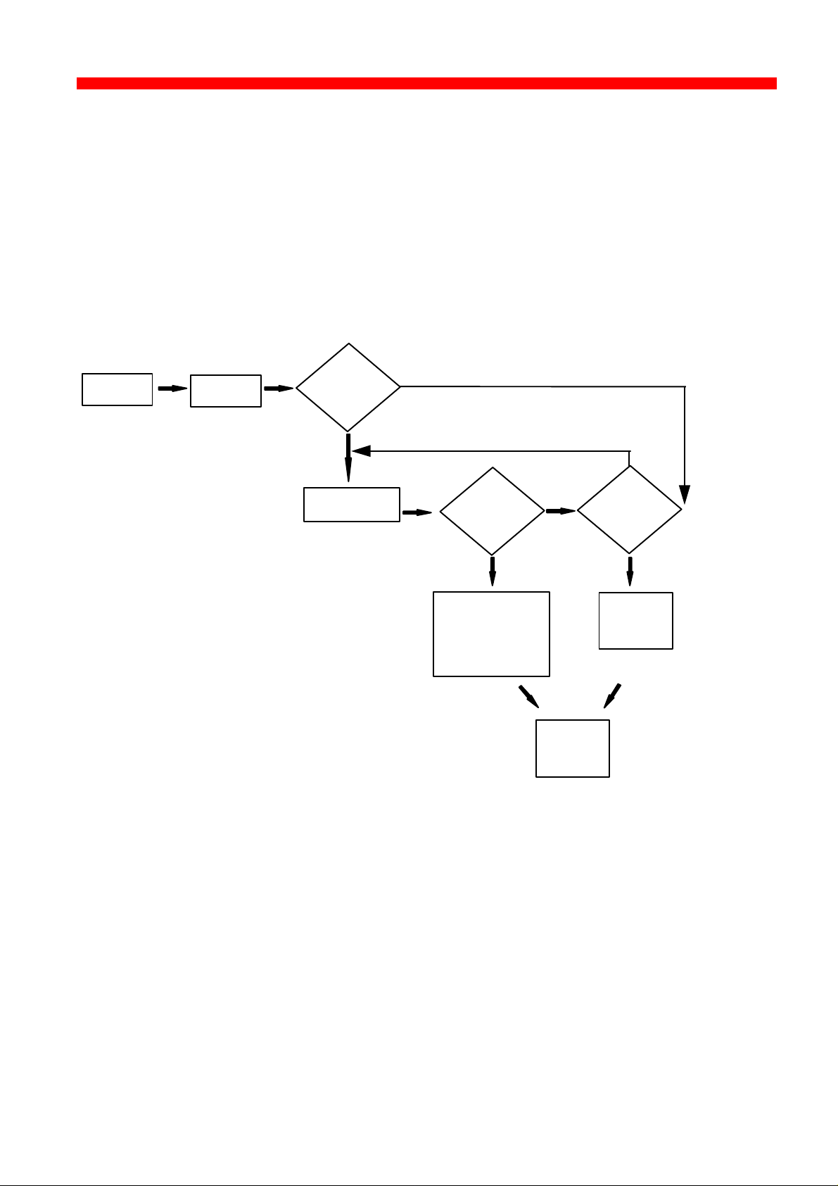
Configuration
Xerox 4500 PS ETH, Inst. & Operator's Guide
3.7.1 BOOTP process
So far, this chapter has only been dealing with the setting up of the
PrintServer from a BOOTP server. However, the PrintServer can also be
equipped with a so-called “ default configuration”. This default
configuration will be carried out if the PrintServer cannot detect a BOOTP
server at the time the PrintServer is powered on. The default settings are
similar to the ones defined on the BOOTP server. For an illustration of this
boot event, please see the flow chart below.
Power ON
Attach to
LAN
Send BOOTP
request
YES
Transmit BOOTP
request
NO
Answer
from BOOTP
server??
Read BOOTPTAB
file:
- IP address
- bootfile (if any)
- microcode file
NO
NO
YES YES
Ready to
print
Default
config.
present??
Load
default
IP address
Default Configuration
79
Page 80

Configuration
Xerox 4500 PS ETH, Inst. & Operator's Guide
3.7.2 Setting up the TFTP Daemon
For the BOOTP server to download the settings to the print server,
TFTP must be enabled.
TFTP in AIX Environment
The TFTP daemon is normally managed by the INETD super-daemon.
The INETD starts a TFTPD when a request is received. The TFTPD
satisfies the request and then dies. You need to configure INETD so that
it performs this service. This can be done in the following way using the
SMIT command (System Management Interface Tool):
NOTE: It can only be done with superuser a uthority (i.e. use the su
command to switch to root user).
1. Type SMIT.
2. Select the following items in order to configure the TFTP daemon.
- Communications Applications and Services
- TCP/IP
- Further Configuration
- Server Network Services
- Other Available Services
- Super Daemon (INETD)
- INETD Subservers
- Add an INETD Subserver
3. When the menu “Available Subservers” appears, use the “LIST”
function .
NOTE: The TFTPD will only be on the list if not already created.
You can also check /etc/inetd.conf to see whether the tftpd line is
commented out. But you should use SMIT to update inetd.conf for
TFTPD. Do not update /etc/inetd.conf manually for TFTPD as you would
for the BOOTPD.
SMIT does not allow you to place the BOOTPD under INETD. The
/etc/inetd.conf file must be updated manually for the BOOTPD.
You should ensure that there is no /etc/tftpaccess.cfg file. It can be used
to control access to files by remote TFTP users.
80
Page 81

Configuration
Xerox 4500 PS ETH, Inst. & Operator's Guide
TFTP in OS/2 Environment
1. Start TCP/IP Configuration located in the TCP/IP folder.
2. Select the Autostart tab.
3. Tick the box labelled "Enable this machine to start the INETD super
server".
4. Tick the box labelled "Enable others to access your files by using
TFTP". Also tick the "INETD" push-button.
5. Shutdown your “TCP/IP Configuration” and check that the new
settings have been saved.
6. Restart the INETD.
81
Page 82

Configuration
Xerox 4500 PS ETH, Inst. & Operator's Guide
3.7.3 Starting the BOOTP Server
This section provides you with instructions for starting the BOOTP
server.
After making the necessary amendments to the BOOTPTAB file, you
are now ready to start the BOOTP server and then verify the
configuration by performing a test printout.
1. Start the BOOTP server
Use the BOOTP server debug option (-d) to verify the correct
operation.
E.g. bootpd -b -d -d -d -d -d
If the PrintServer and the BOOTP server are not on the same LAN
segment, the BOOTP server must be started with the -b option.
This enables the BOOTP reply to cross bridges.
2. Power the PrintServer off and back on.
3. After a while, check that the Power LAN LED stays lit.
4. Proceed to section: “Testing PrintServer”.
82
Page 83

Configuration
Xerox 4500 PS ETH, Inst. & Operator's Guide
3.8 Testing PrintServer
1. Perform a test printout by pressing the TEST key on the rear panel.
2. Verify that the settings match the definitions in the BOOTPTAB file
and the bootfile. Appendix D contains settings printout.
3. ‘’PING’’ the unit from the workstation to verify physical LAN and IP
network connectivity.
a. Invoke the PING command and the IP address or host name of
the unit. For example:
PING 192.0.110.1
b. If the PING is OK, you receive a system response like this:
PING 192.0.110.1: 56 data bytes
64 bytes from 192.0.110.1: icmp_seq=0. time=0.
ms
64 bytes from 192.0.110.1: icmp_seq=1. time=0.
ms
64 bytes from 192.0.110.1: icmp_seq=2. time=0.
ms
64 bytes from 192.0.110.1: icmp_seq=3. time=0.
ms
64 bytes from 192.0.110.1: icmp_seq=4. time=0.
ms
....
....
3. Press CTRL-BREAK to end the PING process. You will then get the
following output statistics:
----192.0.110.1 PING Statistics ---5 packets transmitted, 5 packets received, 0%
packet loss round-trip (ms) min/avg/max 0/0/0
NOTE:
If the PING does not reoccur, only reoccurs once, or if
problems arise with another LAN device, please check the
chapter on “Problem Determination”
83
Page 84

Configuration
Xerox 4500 PS ETH, Inst. & Operator's Guide
3.9 About the PING function
The ICMP PING function sends an echo request to the PrintServer stated
in the IP address. The PING function is useful for:
- Determining the status of the network and various foreign hosts
- Tracking and isolating hardware and software problems.
- Testing, measuring and managing networks.
84
Page 85

Novell Setup for IPX/SPX
Xerox 4500 PS ETH, Inst. & Operator's Guide
4. Novell Setup for IPX/SPX
This chapter provides instructions as to the configuration of Novell
NetWare to connect the PrintServer using the IPX/SPX protocol.
The PrintServer is able to run with NetWare v.3.1x in BINDERY
emulation as well as v.4.xx (the latter being backwards compatible) in
Directory Services (DS) or BINDERY emulation.
The PrintServer supports printing through an embedded PSERVER
(EPS) fully emulating a standard NetWare PSERVER.NLM.
Printing through the embedded NPRINTER (ENP) can also be
performed. Up to two ENPs is supported.
The Novell NetWare protocols supported are: SPX, SAP, NCP and IPX.
The NetWare set-up consists of the following basic steps:
• Check the pre-requisites (described in the section “Before you
begin” in the following).
• Check that the connection with the NetWare server has been
established by printing a file e.g. from a NetWare connected client.
The following sections will guide you through the configuration of the
Novell NetWare for IPX/SPX printing on the PrintServer using standard
NetWare tools.
85
Page 86

Novell Setup for IPX/SPX
Xerox 4500 PS ETH, Inst. & Operator's Guide
4.1 Before you begin.....
Before you proceed to the following sections, please make sure that the
following settings on the PrintServer have been made:
- Enable NetWare
- Enable IPX/SPX
- Set Frametype
These settings can be set by using one of the following configuration
tools:
PSInst32 (see chapter 3)
TELNET (see chapter 3)
Web browser (see chapter 3)
Configuration file (see chapter 3)
The following sections provide instructions for setup of the IPX/SPX
protocol for the embedded PSERVER and the embedded NPRINTER via
the standard NetWare tools PCONSOLE or NetWare Administrator.
4.2 Using the embedded PSERVER
To set up the embedded PSERVER, select either TELNET or the
configuration file as a configuration tool.
The physical location of the embedded PSERVER (EPS) is the Xerox 4500
PS ETH.
4.2.1 Embedded PSERVER setup
To use the embedded PSERVER in the Xerox 4500 PS ETH it must be
defined in the Novell NetWare system and the definitions here must
match the settings made for the PSERVER in the configuration file or
set via the TELNET.
Configuring the EPS via TELNET, see chapter 3.
Configuring via PSInst32, see chapter 3.
Configuring via Web browser, see chapter 3.
Configuring the EPS via configuration file, see chapter 3.
86
Page 87

Novell Setup for IPX/SPX
Xerox 4500 PS ETH, Inst. & Operator's Guide
The following keywords are EPS specific and must be specified either
via TELNET, PSinst32 or via the configuration file.
EPS mode: The PSERVER is able to run in both Bindery
(3.1x) and Directory Service (4.xx) modes.
EPS printserver: The print server name (i.e. logon name).
(NOTE: In DS mode, it must be a typeless distinguished
name, e.g. _PS.international.i-data ######, except if
“Country” is top level of the NDS tree (typefull), it will be
e.g. CN=_PS.OU=international.O=i-data.C=DK
EPS password: The password to use when logging in to the
operating environment (Bindery and DS).
EPS fileserver: The fileserver to where the EPS is to log into.
NOTE: On the Novell Server you must set “Reply
to get nearest server” to ON.
NOTE: The EPS residing in the Xerox 4500 PS ETH is able to support up to
16 ENPs.
4.3 Using the embedded NPRINTER
To setup up the embedded NPRINTER, select either TELNET or the
configuration file as a configuration tool.
The physical location of the embedded NPRINTER is in the Xerox 4500 PS
ETH.
4.3.1 Embedded NPRINTER setup
With the implementation of ENP (NPRINTER) in the Xerox 4500 PS ETH,
the attached printer can be directly connected to the network.
The NPRINTER runs in both Bindery and Directory Services
environments.
The embedded NPRINTER receives the print job from the Novell print
server (PSERVER) or the embedded PSERVER in the PS and prints it.
The embedded NPRINTER supports native print data only (PCL,
PostScript).
The NetWare PCONSOLE or NetWare Administrator are the tools to be
used when setting up the embedded NPRINTER.
Configuring the ENP via TELNET, see chapter 3.
Configuring via PSInst32, see chapter 3.
Configuring via Web browser, see chapter 3
87
Page 88

Novell Setup for IPX/SPX
Xerox 4500 PS ETH, Inst. & Operator's Guide
Configuring the ENP via configuration file, see chapter 3.
The following keywords are ENP specific and must be specified in
either TELNET, PSinst32 or the configuration file.
ENP mode: Selects which mode to use.
ENP printer number: Selects which Novell NetWare
Printserver: Selects which Novell NetWare
Fileserver: Selects which Novell NetWare
NOTE: The Xerox 4500 PS ETH is able to support up to 2 ENPs. Each
Xerox 4500 PS ETH with a defined EPS is able to support up to
16 ENPs.
Options are Bindery and DS mode.
printer number to use.
printserver to use.
fileserver to attach to.
Printing command example
When the user wishes to send a print job to the attached printer, the
following command can be used:
Example:NPRINT MYPRINT Q=PQ2
Where PQ2 is the queue supported by the NPRINTER.
This functionality is set via keyword parameters in the configuration file.
88
Page 89

Novell Setup for IPX/SPX
Xerox 4500 PS ETH, Inst. & Operator's Guide
4.4 NetWare setup - Bindery mode
This section describes the setting up of the NetWare version 3.1x or
later for IPX/SPX printing using Bindery mode. If you use NetWare
version 4.xx you should consider using DS mode as described in the
next section.
NOTE:
You must either load the PSERVER.NLM on the server or define the
embedded PRINTSERVER in the Xerox 4500 PS ETH before
connecting the NPRINTER.
1. Type “PCONSOLE” to start the PCONSOLE program
2. Make sure that you have selected the correct file server. If not, select
the correct by selecting the menu "Change current file server".
3. Select “Print Queue Information” from the main menu to set up a
queue to service the PrintServer.
4. Press INS to create a new queue and type a name for this new
queue. The queue name is user-defined and used for printing and
monitoring.
5. Select the new queue and press ENTER.
6. From the menu “Print Queue Information” select “Queue Server”
and press ENTER.
7. Press INS for a list of Print Servers.
The list will show both non-embedded Print Servers and embedded
Print Servers.
8. Select the appropriate Print Server from the list “Queue Servers
Candidates” and press ENTER.
If defined on the system, one of the candidates is the embedded
Print Server.
9. Press ESC three times to go to the main menu “ Available Options”
and select “Print Server Information”.
10. Select the appropriate Print Server and press ENTER
11. From the “Print Server Information” menu select “Print Server
Configuration”.
89
Page 90

Novell Setup for IPX/SPX
Xerox 4500 PS ETH, Inst. & Operator's Guide
12. Then from the “Print Server Configuration” menu select “Printer
Configuration” and press ENTER
13. From the list “Configured Printers” select either an already
configured printer to change or select one of the printers “ Not
Installed” and press ENTER.
Notice that the number of the printer must correspond to the ENP
number in the PrintServer configuration of ENPs. The default
PrintServer ENP numbers are 0 and 1.
14. Type a name for the printer in the ” Printer X Configuration” menu
15. Select “Type” and press ENTER and select “Remote
Other/Unknown”.
Now make other NPRINTER configuration if so required
16. Press ESC to leave the menu and select YES to save changes.
17. Press ESC to return to the “Print Server Configuration” menu.
18. Select “Queues Serviced by Printer” and press ENTER
19. Select the appropriate printer and press ENTER.
20. Press INS and select the queue for the printer, then press ENTER
21. Select “Priority” for the printer
22. Press ESC six times and answer YES to exit PCONSOLE
Proceed to the configuration of the various settings.
For configuration details, see chapter 3.
90
Page 91
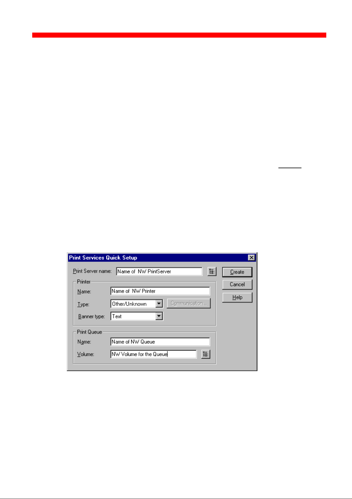
Novell Setup for IPX/SPX
Xerox 4500 PS ETH, Inst. & Operator's Guide
4.5 NetWare setup - DS mode: PrintServer and NW4.1x Configuration
This description allows you to quickly configure one NetWare 4.1X Server
including PrintServer, Printer and Queue plus the Xerox PrintServer for
Native printing via IPX/SPX.
During this description, we will be using the “Nwadmn95/NT” GUI
administration tool for the configuration of NetWare and the i-data
PrintServer Configuration Tool, “PSinst32”, for the configuration of the
Xerox PrintServer.
When setting up, it is important that you make sure you have always
defined a PrintServer, a Printer and a Queue on the NetWare System.
Using the “Print Services Quick Set-up...” you can define all of this in one
step.
Start the Nwadmn95/NT:
Browse through the NDS Tree and highlight the Container Object in which
the PrintServer, Printer and Queue should be located. Select “TOOLS”
from the Menu Bar and then “Print Services Quick Set-up”:
Type in the name of the PrintServer to create it or use the “Browse” button
next to the PrintServer Name window to browse the NDS Tree for existing
PrintServers (only if the EPS is not going to be used in the Xerox
PrintServer, meaning that the PSERVER.NLM is loaded on a NetWare
File Server).
Type in the name of the Printer to be created and set the Type to
“Other/Unknown”.
91
Page 92

Novell Setup for IPX/SPX
Xerox 4500 PS ETH, Inst. & Operator's Guide
Type in the name of the Queue to be created. Use the “Browse” button
next to the “Volume” window to browse the NDS Tree for existing NW
Server Volumes (do not choose SYS Volume).
Finally, click the “Create” button to create the NW PrintServer, Printer and
Queue.
Open the Container where the PrintServer is located and double-click on
the PrintServer. The window below will now be displayed:
NOTE:
Information for EPS Set-up:
“Name” = “EPS PrintServer” in PSinst32:
TEST.cse.international.i-data
(be aware that NDS is case sensitive).
Information for ENP Set-up:
“ENP PrintServer” in PSinst32: TEST
(“ENP PrintServer” do only use the Common Name alone
without the context “cse.international.i-data”)
92
Page 93
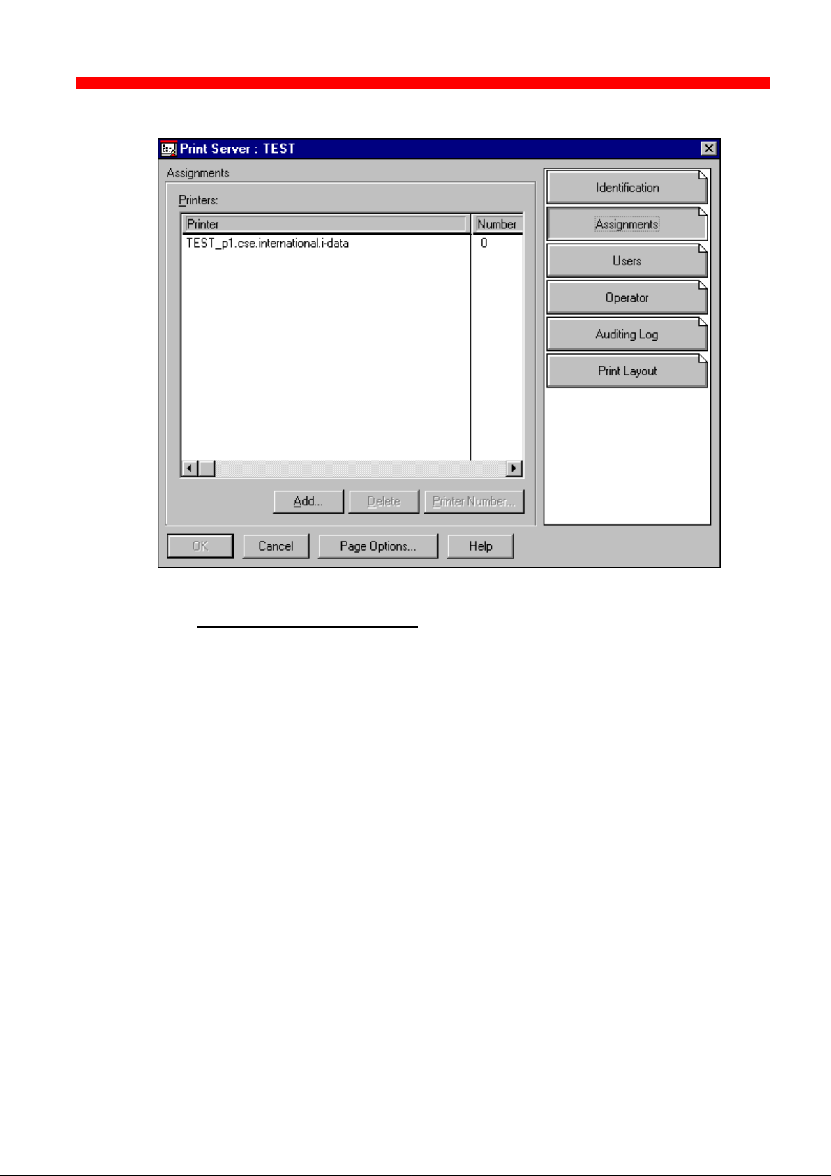
Novell Setup for IPX/SPX
Xerox 4500 PS ETH, Inst. & Operator's Guide
Click the “Assignments” button and the window below will be displayed:
NOTE:
Information for ENP Set-up:
“Number” = “ENP Printer” in PSinst32: 0
In order to verify the “Server Name” + “Frame Type” + “Context” and “Tree
Name”, select “TOOLS” and then “Remote Console” from the
Nwadmn95/NT Menu Bar.
Choose connection type “SPX” and highlight the NetWare Server Name
for which the PrintServer configuration is made. Press ENTER and type in
the password for Rconsole.
Press ALT + F1 to enter “Available Options”. Highlight “Select A Screen
To View” and press ENTER to enter “Available Screens” and select
“System Console”. The command CONFIG should now be executed.
93
Page 94

Novell Setup for IPX/SPX
Xerox 4500 PS ETH, Inst. & Operator's Guide
Below is a screen dump of the System Console after executing the
CONFIG command:
File server name: CSE
IPX internal network number: 336DE04A
Node address: 000000000001
Frame type: VIRTUAL_LAN
LAN protocol: IPX network 336DE04A
Server Up Time: 12 Days 23 Hours 42 Seconds
IBM PCI Token Ring Adapter Hardware Specific Module
Version 1.02 1 June 1996
Hardware setting: Slot 6, I/O ports 4400h to 44FFh, Interrupt Bh
Node address: 0004AC57BC49
Frame type: TOKEN-RING
Board name: IBMTRPO_1_TOK
LAN protocol: IPX network 00002001
IBM PCI Token Ring Adapter Hardware Specific Module
Version 1.02 1 June 1996
Hardware setting: Slot 6, I/O ports 4400h to 44FFh, Interrupt Bh
Node address: 0004AC57BC49
Frame type: TOKEN-RING_SNAP
Board name: IBMTRPO_1_TSP
LAN protocol: ARP
LAN protocol: IP address 128.0.119.100 mask FF.FF.0.0 interfaces 1
Tree Name: IDA
Bindery Context(s):
cse.international.i-data
CSE:
NOTE:
Information for idaPrintServer Set-up:
“File server name” = “NCP Preferred Server” in Psinst32: CSE
“EPS File Server” in Psinst32: CSE
“ENP File Server” in Psinst32: CSE
Information for idaPrintServer Set-up:
“Tree Name” = “NCP Preferred DS-Tree” in PSinst32:
IDA
“Bindery Context” = “NCP DS Context” in PSinst32:
cse.international.i-data
(the first Bindery Context is the context where the NW File
Server is located in the NDS Tree).
94
Page 95
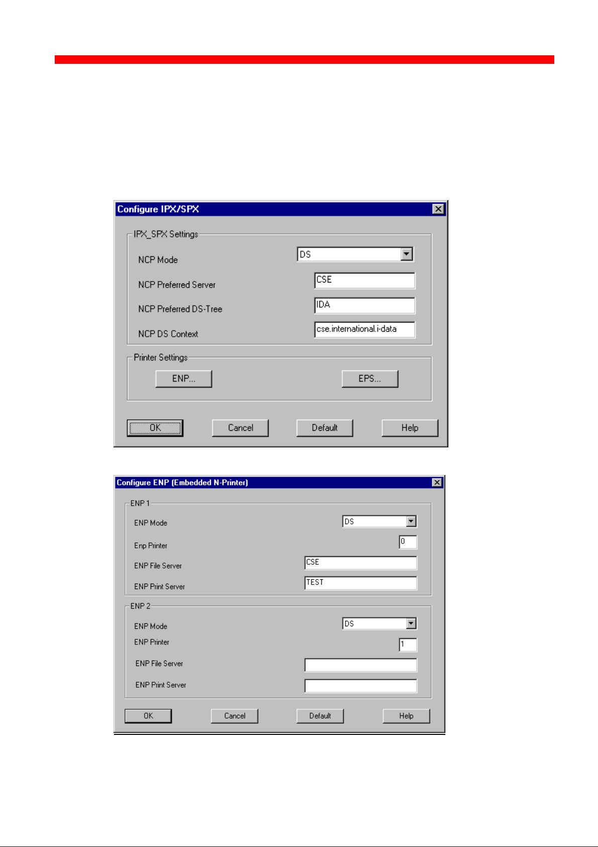
Novell Setup for IPX/SPX
Xerox 4500 PS ETH, Inst. & Operator's Guide
Start the i-data PrintServer Configuration Tool “PSinst32”:
Put in all the collected parameters to reflect the configuration done in
NetWare.
The following are screens from Psinst32 setting up the Xerox PrintServer:
95
Page 96

Novell Setup for IPX/SPX
Xerox 4500 PS ETH, Inst. & Operator's Guide
NOTE:
Disable the EPS if using a PrintServer (PSERVER.NLM)
which is loaded on a NetWare File Server.
4.3.1 Trouble Shooting:
• Preferred Server, EPS File Server or ENP File Server is not correct.
• DS Tree is not correct.
• DS Name context is not correct.
• EPS PrintServer is entered using only the Name and not the Name +
context.
• EPS PrintServer is not entered using Name + full context:
Wrong: TEST.cse.international
Correct: TEST.cse.international.i-data
• If “Country” is top level of the NDS Tree, EPS PrintServer needs to be
the Type-Full Name.
Wrong: TEST.cse.international.i-data.DK
Correct: CN=TEST.OU=cse.OU=international.O=i-data.C=DK
• EPS Password is defined in NetWare and not in idaPS or vice versa.
• Queue has been assigned to the Printer or Printer has not been
assigned to the PrintServer.
• Printer Number is incorrect.
• The ENP’s PrintServer is entered using Name + context.
Wrong: TEST.cse.international.i-data
Correct: TEST
96
Page 97

Novell Setup for IPX/SPX
Xerox 4500 PS ETH, Inst. & Operator's Guide
4.6 Illustration
See the illustration in the following how the print request from the user
is sent to the assigned printer.
Print Queue
Client
Print Queue
PServer
PServer
NPrinter
NPrinter
Novell Server
EPS in
EPS in
ida PrintServer
ida PrintServer
Novell LAN Printing with PrintServer
ENP in
ENP in
ida PrintServer
ida PrintServer
97
Page 98

NetBEUI/NetBIOS Printing Using Windows ‘95, NT or OS/2
PAR2 has been
Xerox 4500 PS ETH, Inst. & Operator's Guide
5. NetBEUI/NetBIOS Printing Using Windows ‘95, NT or OS/2
This chapter provides instructions for setting up the Windows ‘95, NT or
OS/2 operating systems for native printing via the Xerox 4500 PS ETH
using the NetBEUI/NetBIOS protocols.
Before you begin the setup procedure, please ensure that the
NetBEUI/NetNIOS protocols have been properly installed on your
network.
5.1 Windows ‘95 and NT Setup
To set up the Windows ‘95 and NT systems follow the below instructions:
Last 6
digets of
MAC
address
Via the “Network Neighborhood” icon on your desktop, you select the
“entire network” entry. Now open the default “Workgroup”.
The default name of the PrintServer will appear in the workgroup like this:
Only appears if
Now doubleclick the name of the PrintServer for configuration
of the printers available in the PrintServer:
set to output
Again you doubleclick this entry to enter the printer selection mode. You
will encounter the following query to which you answer “yes”:
98
Page 99

NetBEUI/NetBIOS Printing Using Windows ‘95, NT or OS/2
Xerox 4500 PS ETH, Inst. & Operator's Guide
The “Add Printer Wizard” will then open and you may select manufacturor
and printer model via the wizard.
NOTE:
The NP Windows drivers may be obtained from the IBM
Web Site or you may contact your point of purchase for
details.
NOTE:
During the set up, you may need access to the original
installation CDROM for Windows ‘95 and NT.
5.2 OS/2 Setup
To set up the OS/2 operating system follow these instructions:
1. Open an OS/2 window
2. Enter the following command at the prompt:
net view \\ <PrintServer name>
NOTE:
The default PrintServer name is “idaxxxxxx” where the six
“x’es” represent the last six digets of the MAC address
3. Press RETURN
4. Now enter this command:
net use lptx \\idaxxxxxx\Px_Printer_x
5. You have now captured your port for the PrintServer and you next
step is then to install a printer.
[D:\] net view \\ida002efe
Shared resources at \\ida002efe
Net name Type Used as Comment
-----------------------------------------------------------------------------------------------
P1_Printer_1 Print idaPS printer
P2_Printer_2 Print idaPS printer
The command completed successfully.
[D:\] net use lpt1 \\ida002efe\P1_Printer_1
The command completed successfully.
Example of setup for OS/2
99
Page 100

NetBEUI/NetBIOS Printing Using Windows ‘95, NT or OS/2
Xerox 4500 PS ETH, Inst. & Operator's Guide
5.3 Changing the default PrintServer Name & Workgroup
This can be done using any of the available configuration methods:
Psinst32: see section 3.3
Web Browser: see section 3.4
Telnet: see section 3.5
Setup file: see section 3.6
100
 Loading...