

Page 1

laser printer
Service
Manual
Phaser™ 4500
Page 2

Page 3

Page 4

Phaser 4500 Laser Printer
Service Manual
Warning
The following servicing instructions are for use by qualified service
personnel only. To avoid personal injury, do not perform any servicing other
than that contained in the operating instructions, unless you are qualified to
do so.
First Printing: January 2004
071-0867-00
Page 5

Page 6

Page 7

Service Manual
iii
Contents
Service Terms ............................................................................. xiii
Product Terms ............................................................................xiv
Power Safety Precautions ........................................................... xv
Electrostatic Discharge (ESD) Precautions .................................. xvi
Service Safety Summary ............................................................ xvii
Regulatory Specifications ............................................................xix
1
General Information
Printer Introduction and Overview ............................................... 1-2
Technical Support Information .......................................... 1-2
Printer Configurations ................................................................. 1-3
Parts of the Printer...................................................................... 1-4
Front Panel .........................................................................................1-5
Image Processor Board .............................................................. 1-6
Consumables and Routine Maintenance Items ............................ 1-7
Supply Life Counters ........................................................ 1-8
Printer Specifications.................................................................. 1-9
Physical Dimensions and Clearances................................ 1-9
Functional Specifications ................................................ 1-10
Electrical Specifications .................................................. 1-11
Environmental Specifications .......................................... 1-11
Media and Tray Specifications ................................ ........ 1-12
Memory Requirements ................................................... 1-13
2
Theory of Operation
Overview of the Phaser 4500 Laser Printer .................................. 2-2
Summary of the Printing Process ...................................... 2-2
Paper Path of the Printer ............................................................ 2-5
Layout of Paper Transport Path ........................................ 2-6
Sensors ..................................................................................... 2-8
Major Assemblies and Functions .............................................. 2-12
Paper Tray .............................................................................2-12
Paper Feeder .........................................................................2-16
Control of Paper Size...................................................... 2-18
Xerographics .................................................................. 2-19
Fuser ............................................................................. 2-24
Fuser Control ................................................................. 2-26
Paper Exit Assembly ...................................................... 2-29
Drive .............................................................................. 2-30
Electrical ........................................................................ 2-31
Page 8

Phaser 4500 Laser Printer
Printer Options ................................................................ ......... 2-34
Duplex Unit .................................................................... 2-34
Stacker .......................................................................... 2-37
Optional 550-Sheet Feeder ................................................... 2-41
3
Error Messages and Codes
Introduction ................................................................................ 3-2
Servicing Instructions ................................................................. 3-2
Using the Troubleshooting Procedures .............................. 3-4
General Notes on Troubleshooting .................................... 3-4
Accessing Fault Histories ..................................................3-6
Entry Level Fault Isolation Procedure ..........................................3-8
Service Diagnostics .................................................................... 3-9
Service Diagnostic Front Panel Button Descriptions .......... 3-10
Using Service Diagnostics .............................................. 3-10
System Start-Up and POST ...................................................... 3-16
Power On Self Test (POST) ................................................... 3-16
POST Faults .......................................................................... 3-17
LED Blink Patterns ......................................................... 3-17
POST Diagnostic Test Descriptions ................................. 3-18
Operating System and Application Problems ............................. 3-20
Macintosh Printing Problems .......................................... 3-20
Windows Printing Problems ............................................ 3-20
Network Problems .......................................................... 3-21
Error Messages and Codes Troubleshooting Procedures ............ 3-22
Main Motor Failure .......................................................... 3-26
Laser Unit Failure ........................................................... 3-27
Fuser Failure ......................................................................... 3-28
Fan Failure ............................................................................ 3-29
Engine Logic Board NVRAM Failure ...................................... 3-31
Jam At Tray N ........................................................................ 3-32
Jam at Tray N ........................................................................ 3-35
Jam At Top; Open Top Cover To Clear .................................. 3-38
Jam At Exit; Open Rear/Top Cover To Clear .......................... 3-41
Jam At Rear; Open Rear Cover To Clear. .............................. 3-43
Jam At Stacker; Open Rear Stacker Cover To Clear .............. 3-45
Jam At Rear; Open Duplex And Rear Cover To Clear ............. 3-47
Jam At Duplex; Open Duplex To Clear .................................. 3-49
Duplex Unit Error ............................................................ 3-50
Stacker Error ................................................................ .. 3-51
Tray 3 Failure\ Tray 3 or 4 Failure. ......................................... 3-52
Paper Size Jam ..................................................................... 3-54
Close Top Cover/Close Rear Cover....................................... 3-56
Close Duplex Unit Cover ................................................. 3-57
Close Stacker Cover .............................................................. 3-58
Page 9

Service Manual
v
Install or Reseat Print Cartridge ....................................... 3-59
Replace Print Cartridge .................................................. 3-60
No Paper in Tray 1/No Paper in Tray 2 ............................. 3-61
Tray 2 Paper Is Low ........................................................ 3-62
No Paper in Tray 3/No Paper in Tray 4 ............................. 3-63
Tray 3 Paper Is Low/Tray 4 Paper Is Low ......................... 3-64
Insert Tray 1/Insert Tray 2 ............................................... 3-65
Insert Tray 3/Insert Tray 4 ............................................... 3-66
Stacker Is Full, Unload Paper .......................................... 3-67
Standard Output Tray Is Full, Unload Paper ..................... 3-68
Replace Maintenance Kit ................................................ 3-69
Inoperable Printer. .......................................................... 3-70
No Recognition of Duplex Unit ........................................ 3-71
No Recognition of Stacker .............................................. 3-73
4
General Troubleshooting
Introduction ................................................................................ 4-2
Front Panel Troubleshooting ....................................................... 4-3
LCD/LED Display Error/Inoperable Buttons ....................... 4-3
DC Power Supply Troubleshooting .............................................. 4-4
LVPS (Low Voltage Power Supply) ................................... 4-4
DC-DC Converter .................................................................... 4-5
AC Power Supply Troubleshooting ..............................................4-7
No AC Power ........................................................................... 4-7
Print Engine Troubleshooting .................................................... 4-11
Main Motor ................................ ................................ ..... 4-11
Laser Unit Assembly ....................................................... 4-13
Fuser Assembly ............................................................. 4-16
Registration Sensor ........................................................ 4-18
No Paper Sensor ............................................................ 4-20
Low Paper Sensor .......................................................... 4-22
Toner Sensor ................................................................. 4-23
Output Tray Stack Full Sensor ............................................... 4-25
24 V Interlock ................................................................. 4-26
5 V Interlock, Interlock Switch Assembly .......................... 4-26
Rear Cover Switch.......................................................... 4-28
Interlock Switch Assembly .............................................. 4-29
Exit Motor PWBA ............................................................ 4-30
Exit Motor Assembly ....................................................... 4-31
Registration Clutch ......................................................... 4-32
Feed Clutches ....................................................................... 4-33
Left Tray Guide............................................................... 4-34
HVPS/Engine Logic Board .............................................. 4-35
Image Processor Isolation .............................................. 4-37
Image Processor Board ................................ .................. 4-38
Page 10

Phaser 4500 Laser Printer
RAM DIMM Fault Isolation .............................................. 4-39
Electrical Noise .............................................................. 4-41
Optional 550-Sheet Feeder PWBA (Tray 3) ...................... 4-43
Optional 550-Sheet Feeder PWBA (Tray 4) ...................... 4-44
Optional 550-Sheet Feeder No Paper Sensor ........................ 4-45
Optional 550-Sheet Feeder Low Paper Sensor ...................... 4-47
Optional Feeder Paper Size Switch Assembly ....................... 4-49
Optional 550-Sheet Feeder Feed Clutch Assembly ................ 4-50
Optional 550-Sheet Feeder Turn Roller Clutch ................. 4-52
Duplex Unit PWBA ......................................................... 4-54
Duplex Unit Motor ........................................................... 4-55
Duplex Unit Sensor ......................................................... 4-56
Duplex Unit Switch ......................................................... 4-58
Stacker PWBA ....................................................................... 4-59
Stacker Motor Assembly ................................................. 4-60
Offset Motor Assembly ................................................... 4-61
Gate Solenoid Assembly................................................. 4-62
Stacker Rear Cover Switch.................................................... 4-63
Stacker Sensor ............................................................... 4-65
Stack Full Sensor (On Stacker PWBA) .................................. 4-67
Offset Sensor (On Stacker PWBA) ........................................ 4-69
5
Print-Quality Troubleshooting
Print-Quality Problems Overview ................................................ 5-2
Analyzing Test Prints ................................................................ .. 5-3
Deletions (Line, Band, Spots) ............................................ 5-6
Fusing .............................................................................. 5-7
Resolution ................................ ................................ ........ 5-9
Registration (Side-to-Side) ............................................. 5-10
Registration (Lead Edge-to-Trail Edge) ........................... 5-11
Skips/Smears ................................................................. 5-12
Spots ............................................................................. 5-13
Skew ................................................................ .............. 5-14
Other Print Defects ......................................................... 5-15
Print-Quality Troubleshooting.................................................... 5-16
Light (Undertoned) Print ................................................. 5-16
Blank Print (No print) ...................................................... 5-18
Black Prints ................................ ................................ .... 5-20
Vertical Deletions ........................................................... 5-21
Horizontal Deletions ....................................................... 5-23
Vertical Streaks ................................ .............................. 5-25
Horizontal Streaks .......................................................... 5-28
Spots ............................................................................. 5-30
Unfused Image ............................................................... 5-32
Damaged Print ............................................................... 5-35
Page 11

Service Manual
vii
Resolution ................................ ................................ ...... 5-36
Spot Deletions ................................................................ 5-37
Repeating Defects .......................................................... 5-39
Residual Image. ............................................................. 5-40
Background .................................................................... 5-42
Uneven Density .............................................................. 5-43
Skewed Image ............................................................... 5-44
Registration .................................................................... 5-47
Skips and Smears ................................ .......................... 5-49
6
Adjustments and Calibrations
Service Test Prints ..................................................................... 6-2
Test Prints ........................................................................ 6-2
Engine Test Print .............................................................. 6-4
Adjustments ............................................................................... 6-5
Adjusting Laser Power (Image Density) .............................6-5
Checking Registration ......................................................6-5
Adjusting Simplex Registration ......................................... 6-7
Adjusting Duplex Registration ........................................... 6-8
Adjusting Fuser Temperature ............................................ 6-9
Resetting Fuser Life.................................................................. 6-10
Resetting Printer Values to the Factory Default Values ................ 6-11
Resetting Connection Setup Values ................................ 6-11
Resetting Paper Handling Setup Values ................................ 6-12
Resetting PostScript Setup Values .................................. 6-12
Resetting PCL Setup Values ................................................. 6-12
Resetting General Setup Values ........................................... 6-12
Resetting Front Panel Setup Values ...................................... 6-13
Resetting Printer Controls Setup Values .......................... 6-13
Resetting File Security Setup Values ..................................... 6-13
Resetting All Printer Default Settings (PostScript NVRAM) ..... 6-14
7
Cleaning and Maintenance
Service Preventive Maintenance Procedure ................................ 7-2
Recommended Tools .................................................................7-2
Cleaning ..................................................................................... 7-2
8
FRU Disassembly
Overview .................................................................................... 8-2
Standard Orientation of the Printer .................................... 8-2
General Notes on Disassembly ...................................................8-3
Preparation ...................................................................... 8-3
Notations in the Disassembly Text.....................................8-3
Print Engine: Covers ................................................................... 8-4
Page 12

Phaser 4500 Laser Printer
Paper Exit Cover ..................................................................... 8-4
Paper Exit Rear Door .............................................................. 8-5
Rear Cover .............................................................................. 8-6
Right Cover ...................................................................... 8-7
Page 13

Page 14

viii
Phaser 4500 Laser Printer
Left Cover ........................................................................8-9
Top Cover Assembly, Front Panel ......................................... 8-10
Front Cover .................................................................... 8-12
Interlock Switch Assembly .............................................. 8-13
Print Engine: 150- or 550-Sheet Paper Cassette ........................ 8-15
Retard Roller and Holder ................................................ 8-15
Print Engine: 150-Sheet Feeder ................................................ 8-18
150-Sheet Feeder Assembly ................................................. 8-18
Nudger Roller, Feed Roller.............................................. 8-20
Nudger One-way Clutch .................................................. 8-22
Nudger Gear .......................................................................... 8-24
Feed Clutch, Registration Clutch ................................ ..... 8-26
Registration Sensor ........................................................ 8-27
No Paper Sensor ................................................................... 8-28
Toner Sensor Assembly.................................................. 8-30
Print Engine: 550-Sheet Paper Feeder ...................................... 8-31
550-Sheet Feeder Assembly ................................................. 8-31
Nudger Roller, Feed Roller.............................................. 8-32
Nudger One-way Clutch .................................................. 8-33
Nudger Gear .......................................................................... 8-34
Feed Clutch ........................................................................... 8-36
No Paper Sensor ................................................................... 8-38
Right Tray Guide ................................ ............................ 8-39
Left Tray Guide ............................................................... 8-41
Low Paper Sensor/Actuator ............................................ 8-42
Print Engine: Xerographics ....................................................... 8-44
Front Duct, Sub Fan........................................................ 8-44
Laser Unit Assembly ....................................................... 8-46
Laser Unit Shield Plate ................................................... 8-48
Print Cartridge Left Guide ............................................... 8-49
Fuser Harness Assembly ................................................ 8-50
Link Lever, Gear 3 Link .......................................................... 8-52
Fuser Assembly.............................................................. 8-54
Transfer Roller Assembly ................................................8-55
Transfer Chute ............................................................... 8-56
Print Cartridge Right Guide Assembly .............................. 8-58
Duplex Unit Opening Cover ............................................. 8-60
Print Engine: Paper Exit ............................................................ 8-61
Paper Exit Assembly....................................................... 8-61
Upper Exit Chute, Lower Exit Chute ...................................... 8-63
Exit Motor Assembly ....................................................... 8-64
Stack Full Sensor ........................................................... 8-65
Stack Full Actuator.......................................................... 8-66
Page 15

Service Manual
4you.com
Print Engine: Frame and Drive .................................................. 8-67
Motor Cover ................................................................... 8-67
Main Motor ..................................................................... 8-69
Gear Assembly Housing ................................................. 8-71
Gear Assembly Plate .............................................................8-73
Print Engine: Electrical ............................................................. 8-75
LVPS Shield Plate .................................................................8-75
Exit Motor PWBA............................................................ 8-76
Low Voltage Power Supply (LVPS) ................................. 8-78
DC-DC Converter ..................................................................8-80
Power Switch, AC Power Harness Assembly ................... 8-81
Rear Cover Switch ......................................................... 8-83
Main Fan. ....................................................................... 8-84
Image Processor Shield Assembly .................................. 8-86
I/P Shield Window .......................................................... 8-87
HVPS Shield Plate .................................................................8-88
HVPS/Engine Logic Board .............................................. 8-89
Image Processor (I/P) Board ........................................... 8-91
Options: 550-Sheet Paper Feeder ................................................... 8-93
550-Sheet Paper Feeder Removal ........................................8-93
Right Cover Plate ........................................................... 8-95
Left Cover Plate ............................................................. 8-97
Option Paper Size Switch Assembly ................................ 8-99
Optional Feeder Drive Assembly ................................... 8-100
550-Sheet Feeder PWBA ................................................... 8-102
550-Sheet Feeder ................................................................8-104
Nudger Roller, Feed Roller ........................................... 8-106
Nudger One-way Clutch ............................................... 8-107
Nudger Gear ........................................................................8-108
Feed Clutch Assembly .........................................................8-110
Turn Roller Clutch ........................................................ 8-112
Retard Roller ................................................................ 8-113
Options: Duplex Unit............................................................... 8-115
Duplex Unit Removal .................................................... 8-115
Left Cover .................................................................... 8-117
Right Cover .................................................................. 8-118
Top Cover ................................ .................................... 8-119
Upper Assembly Housing ............................................. 8-120
Duplex Unit Lower Housing........................................... 8-121
Duplex Unit PWBA ....................................................... 8-123
Duplex Unit Fan ...................................................................8-124
Duplex Unit Sensor ...................................................... 8-126
Duplex Unit Roller ........................................................ 8-127
Duplex Unit Motor......................................................... 8-129
Duplex Unit Switch ....................................................... 8-131
Page 16

x
Phaser 4500 Laser Printer
Options: Stacker ................................ ................................ ..... 8-132
Stacker Removal .......................................................... 8-132
Stacker Rear Cover ............................................................. 8-133
Stacker Cover ...................................................................... 8-134
Stacker Front Cover ..................................................... 8-137
Stacker Tray Assembly ................................................. 8-138
Stack Full Actuator ....................................................... 8-139
Stacker PWBA ..................................................................... 8-142
Offset Motor Assembly ................................................. 8-144
Gate Solenoid Assembly ............................................... 8-145
Stacker Sensor and Actuator ........................................ 8-146
Stacker Rear Cover Interlock Switch ............................. 8-148
Lower Stacker Roller .................................................... 8-149
Upper Stacker Roller .................................................... 8-151
Stacker Motor Assembly ............................................... 8-154
9
Parts Lists
Serial Number Format ................................................................ 9-2
Using the Parts List..................................................................... 9-3
Print Engine Parts....................................................................... 9-4
Parts List 1.1 Covers ................................ ........................ 9-4
Parts List 2.1 150-Sheet Paper Cassette ........................... 9-6
Parts List 4.1 550-Sheet Paper Cassette ........................... 9-9
Parts List 5.1 150-Sheet Paper Feeder ............................ 9-12
Parts List 7.1 550-Sheet Paper Feeder ............................ 9-15
Parts List 8.1 Xerographics ................................ ............. 9-18
Parts List 10.1 Paper Exit (1/2) ........................................ 9-20
Parts List 10.2 Paper Exit (2/2) ........................................ 9-22
Parts List 11.1 Frame and Drive ...................................... 9-24
Parts List 12.1 Electrical ................................................. 9-26
Options ................................ ................................ .................... 9-29
Parts List 20.1 550-Sheet Paper Feeder (1/2) ................... 9-29
Parts List 20.2 550-Sheet Paper Feeder (2/2) ................... 9-32
Parts List 20.3 Optional 550-Sheet Paper Cassette ........... 9-34
Parts List 21.1 Duplex Unit .............................................. 9-37
Parts List 23.1 Stacker .................................................... 9-40
Xerox Supplies and Accessories ............................................... 9-43
10
Wiring Diagrams
Introduction .............................................................................. 10-2
Print Engine Plug/Jack Locator ................................................. 10-3
550-Sheet Feeder Plug/Jack Locator ...................................... 10-10
Duplex Unit Plug/Jack Locator ................................................ 10-12
Stacker Plug/Jack Locator ...................................................... 10-14
Page 17

Service Manual
4you.com
Notations Used in Wiring Diagrams ..................................................
10-15
Print Engine Wiring Diagrams ..........................................................
10-17
Print Engine General Wiring Diagram .....................................
10-17
24 V Interlock, Rear Cover Switch, Main Motor, Sub Fan, Exit Motor
Assembly ........................................................................
10-18
Fuser Assembly, Power Switch ..............................................
10-20
Print Cartridge, Transfer Roller Assembly ...............................
10-21
150-Sheet Feeder, 550-Sheet Feeder, Main Fan ......................
10-22
Laser Unit, 5 V Interlock, Interlock Switch Assembly ..............
10-24
Paper Exit ............................................................................ 10-25
Image Processor Board, DC-DC Converter, Front Panel ...........
10-26
Optional 550-Sheet Feeder ...............................................................
10-27
550-Sheet Feeder General Wiring Diagram .............................
10-27
550-Sheet Feeder Signal Diagram ..........................................
10-28
Duplex Unit .....................................................................................
10-29
Duplex Unit General Wiring Diagram ......................................
10-29
Duplex Unit Signal Diagram ..................................................
10-30
Stacker ...........................................................................................
10-31
Stacker General Wiring Diagram ............................................
10-31
Stacker Signal Diagram .........................................................
10-32
A Appendix
Menu Map .................................................................................. A-2
Service Diagnostics Menu Map . . . . . . . . . . . . . . . . . . . . . . . . . . . . . . . . A-4
Index
Page 18

xii
Phaser 4500 Laser Printer
Page 19

Service Manual
4you.com
Service Terms
Manual Terms
Various terms are used throughout this manual to either provide additional
information on a specific topic or to warn of possible danger present during a
procedure or action. Be aware of all symbols and terms when they are used, and
always read NOTE, CAUTION, and WARNING statements.
Consumable: Ink, toner, or print cartridge that is consumed. Customer is expected
to replace once consumed.
Routine Maintenance Item: Supply item or kit that has a limited life. Customer
is expected to replace at end-of-life.
Accessory: A single component or assembly that may be added to a printer;
however, it is NOT an option to the product.
Common Acronyms:
FRU: Field Replaceable Unit
PL: Corresponds to the FRU Parts List.
CRU: Customer Replaceable Unit
ESD: Electrostatic Discharge
Note
A note indicates an operating or maintenance procedure, practice or condition
that is necessary to efficiently accomplish a task.
A note can provide additional information related to a specific subject or add a
comment on the results achieved through a previous action.
Caution
A caution statement indicates an operating or maintenance procedure, practice or
condition that, if not strictly observed, results in damage to, or destruction of,
equipment.
Warning
A warning statement indicates an operating or maintenance procedure, practice
or condition that, if not strictly observed, results in injury or loss of life.
Page 20

xiv
Phaser 4500 Laser Printer
Product Terms
Caution: A personal injury hazard exists that may not be apparent. For example, a
panel may cover the hazardous area.
Danger: A personal injury hazard exists in the area where you see the sign.
Symbols Marked on the Product
DANGER high voltage.
Protective ground (earth) symbol.
Hot surface on or in the printer. Use caution to avoid personal
injury.
The surface is hot while the printer is running. After turning off
the power, wait 30 minutes.
Avoid pinching fingers in the printer. Use caution to avoid
personal injury.
Use caution (or draws attention to a particular component).
Refer to the manual(s) for information.
0
30min.
Page 21

Service Manual
4you.com
Power Safety Precautions
Power Source
For 110 VAC printers, do not apply more than 140 volts RMS between the supply
conductors or between either supply conductor and ground. Use only the specified
power cord and connector. For 220 VAC printers, do not apply more than 264 volts
RMS between the supply conductors or between either supply conductor and ground.
Use only the specified power cord. This manual assumes that the reader is a Xeroxcertified service technician.
Plug the three-wire power cord (with grounding prong) into a grounded AC outlet
only. If necessary, contact a licensed electrician to install a properly grounded outlet.
If the product loses its ground connection, contact with conductive parts may cause an
electrical shock.
Disconnecting Power
Turning the power off using the On/Off switch does not completely de-energize the
printer. You must also disconnect the printer power cord from the AC outlet. Position
the power cord so that it is easily accessible during servicing so that you may power
down the printer during an emergency.
■
Disconnect the power plug by pulling the plug, not the cord.
■
Disconnect the power cord in the following cases:
■
if the power cord or plug is frayed or otherwise damaged,
■
if any liquid or foreign material is spilled into the case,
■
if the printer is exposed to any excess moisture,
■
if the printer is dropped or damaged,
■
if you suspect that the product needs servicing or repair,
■
whenever you clean the product.
Page 22

xvi
Phaser 4500 Laser Printer
Electrostatic Discharge (ESD) Precautions
Some semiconductor components, and the respective sub-assemblies that contain
them, are vulnerable to damage by Electrostatic discharge (ESD). These components
include Integrated Circuits (ICs), Large-Scale Integrated circuits (LSIs), field-effect
transistors and other semiconductor chip components. The following techniques will
reduce the occurrence of component damage caused by static electricity.
Be sure the power is off to the chassis or circuit board, and observe all other safety
precautions.
■
Immediately before handling any semiconductor components assemblies, drain
the electrostatic charge from your body. This can be accomplished by touching an
earth ground source or by wearing a wrist strap device connected to an earth
ground source. Wearing a wrist strap will also prevent accumulation of additional
bodily static charges. Be sure to remove the wrist strap before applying power to
the unit under test to avoid potential shock.
■
After removing a static sensitive assembly from its anti-static bag, place it on a
grounded conductive surface. If the anti-static bag is conductive, you may ground
the bag and use it as a conductive surface.
■
Do not use freon-propelled chemicals. These can generate electrical charges
sufficient to damage some devices.
■
Do not remove a replacement component or electrical sub-assembly from its
protective package until you are ready to install it.
■
Immediately before removing the protective material from the leads of a
replacement device, touch the protective material to the chassis or circuit
assembly into which the device will be installed.
■
Minimize body motions when handling unpackaged replacement devices. Motion
such as your clothes brushing together, or lifting a foot from a carpeted floor can
generate enough static electricity to damage an electro-statically sensitive device
■
Handle ICs and EPROMs carefully to avoid bending pins.
■
Pay attention to the direction of parts when mounting or inserting them on
Printed Circuit Boards (PCB’s).
Page 23

Service Manual
4you.com
Service Safety Summary
General Guidelines
For Xerox-certified service personnel only: Refer also to the preceding Power
Safety Precautions.
Avoid servicing alone: Do not perform internal service or adjustment of this
product unless another person capable of rendering first aid or resuscitation is present.
Use care when servicing with power: Dangerous voltages may exist at several
points in this product. To avoid personal injury, do not touch exposed connections and
components while power is on. Disconnect power before removing the power supply
shield or replacing components.
Do not wear jewelry: Remove jewelry prior to servicing. Rings, necklaces and
other metallic objects could come into contact with dangerous voltages and currents.
Power source: This product is intended to operate from a power source that will
not apply more then 264 volts rms for a 220 volt AC outlet or 140 volts rms for a 110
volt AC outlet between the supply conductors or between either supply conductor and
ground. A protective ground connection by way of the grounding conductor in the
power cord is essential for safe operation.
Warning Labels
Read and obey all posted warning labels. Throughout the printer, warning labels are
displayed on potentially dangerous components. As you service the printer, check to
make certain that all warning labels remain in place.
Safety Interlocks
Make sure all covers and the printer’s front panel are in place and all interlock
switches are functioning correctly after you have completed a printer service call. If
you bypass an interlock switch during a service call, use extreme caution when
working on or around the printer.
CLASS 1 LASER PRODUCT
The Phaser 4500 Laser Printer is certified to comply with Laser Product Performance
Standards set by the U.S. Department of Health and Human Services as a Class 1
Laser Product. This means that this is a class of laser product that does not emit
hazardous laser radiation; this is possible only because the laser beam is totally
enclosed during all modes of customer operation. When servicing the printer or laser
unit, follow the procedures specified in this manual and there will be no hazards from
the laser.
Page 24

xviii
Phaser 4500 Laser Printer
S7300-02
S7300-03
Servicing Electrical Components
Before starting any service procedure, switch off the printer power and unplug the
power cord from the wall outlet. If you must service the printer with power applied,
be aware of the potential for electrical shock.
Warning
Turning the power off by using the On/Off switch does not completely deenergize the printer. You must also disconnect the printer power cord from the
AC outlet. Position the power cord so that it is easily accessible during servicing.
Warning
Do not touch any electrical component unless you are instructed to do so by a
service procedure.
Servicing Mechanical Components
When servicing mechanical components within the printer, manually rotate drive
assemblies, rollers, and gears.
Warning
Do not try to manually rotate or manually stop the drive assemblies while any
printer motor is running.
Servicing Fuser Components
Warning
This printer uses heat to fuse the toner image to media. The Fuser Assembly is
VERY HOT. Turn the printer power off and wait at least 5 minutes for the Fuser
to cool before you attempt to service the Fuser Assembly or adjacent
components.
Page 25

Service Manual
4you.com
Regulatory Specifications
Federal Communications Compliance
The equipment described in this manual generates and uses radio frequency energy. If
it is not installed properly in strict accordance with Xerox instructions, it may cause
interference with radio and television reception or may not function properly due to
interference from another device. However, there is no guarantee that interference
will not occur in a particular installation. If this equipment does cause harmful
interference to radio or television reception, which can be determined by turning the
equipment off and on, the user is encouraged to try to correct the interference by one
or more of the following measures:
■
Reorient or relocate the receiver (device being interfered with).
■
Increase the separation between the printer and the receiver.
■
Connect the printer into an outlet on a circuit different from that which the
receiver is connected.
■
Route the interface cables on the printer away from the receiver
■
Consult the dealer, Xerox service, or an experienced radio/television
technician for help.
Changes or modifications not expressly approved by Xerox can affect the emission
and immunity compliance and could void the user's authority to operate this product.
To ensure compliance, use shielded interface cables. A shielded parallel cable can be
purchased directly from Xerox at www.xerox.com/office/4500supplies.
Xerox has tested this product to internationally accepted electromagnetic emission
and immunity standards. These standards are designed to mitigate interference caused
or received by this product in a normal office environment. This product is also
suitable for use in a residential environment based on the levels tested.
In the United States this product complies with the requirements of an unintentional
radiator in part 15 of the FCC rules. Operation is subject to the following two
conditions: (1) this device may not cause harmful interference; (2) this device must
accept any interference received, including interference that may cause undesired
operation.
This digital apparatus does not exceed the Class B limits for radio noise emissions
from digital apparatus set out in the Radio Interference Regulations of the Canadian
Department of Communications, ICES-003.
Le présent appareil numérique n'émet pas de bruits radioélectrique dépassant les
limits applicables aux appareils numériques de la classe B prescrites dans le
Réglement sur le brouillage radioélectrique édicté par le ministere des
Communications du Canada, NMB-003.
Page 26

xx
Phaser 4500 Laser Printer
Declaration of Conformity
Xerox Corporation, declares, under our sole responsibility that the printer to which
this declaration relates, is in conformity with the following standards and other
normative documents:
In the European Union
following the provisions of the Low Voltage Directive 73/23/EEC and its
amendments:
EN 60950
(IEC 60950)
“Safety of Information Technology Equipment including Electrical Business
Equipment”
following the provisions of the Electromagnetic Compatibility Directive 89/336/EEC
and its amendments:
EN 55022:1998
(CISPR 22)
EN 61000-3-2:1995
+A1:1998+A2:1998
(IEC 61000-3-2)
EN 61000-3-3:1995
(IEC 61000-3-3)
EN 55024:1998
(CISPR 24)
“Limits and Methods of measurement of radio interference
characteristics of Information Technology Equipment.” Class B.
“Part 3: Limits - Section 2: Limits for harmonic current emissions
(equipment input current less than or equal to 16A per phase).”
“Part 3: Limits - Section 3: Limitation of voltage fluctuations and flicker
in low-voltage supply systems for equipment with rated current less
than or equal to 16A.”
“Information technology equipment - Immunity characteristics - Limits
and methods of measurement. “
This product, if used properly in accordance with the user's instructions is neither
dangerous for the consumer nor for the environment. A signed copy of the
Declaration of Conformity for this product can be obtained from Xerox.
Page 27

Service Manual
4you.com
General
Information
In this chapter...
■
Printer Introduction and Overview
■
Printer Configurations
■
Parts of the Printer
■
Front Panel
■
Image Processor Board
■
Consumables and Routine Maintenance Items
■
Printer Specifications
Chapter
1
Page 28

1-2
Phaser 4500 Service Manual
Printer Introduction and Overview
The Xerox Phaser 4500 Laser Printer Service Manual is the primary document used
for repairing, maintaining, and troubleshooting the printer.
To ensure complete understanding of this product, participation in Xerox Phaser 4500
Service Training is strongly recommended. To service this product, Xerox
certification for this product is required.
Technical Support Information
s4500-001
For updates to the Service Manual, Service Bulletins, knowledge base, etc., go to
www.office.xerox.com/partners.
For further technical support, contact your assigned Xerox Technical Support for this
product.
Page 29

[Type here]
Printer Configurations
A replaceable Configuration Card holds configuration information that enables or
disables the network features shown in the following table.
Printer Configuration
Features
4500B 4500N 4500DT 4500DX
Maximum Print Speed (Letter-size
Paper)
36 ppm 36 ppm 36 ppm 36 ppm
Memory 48 MB 64 MB 64 MB 64 MB
PostScript Fonts 39 39 39 39 +
97 on
hard drive
PCL5e/PCL6 Yes Yes Yes Yes
Job Pipelining Standard Standard Standard Standard
PDF Direct Print Yes Yes Yes Yes
Resolutions 600 dpi,
True 1200
dpi
600 dpi,
True 1200
dpi
600 dpi,
True 1200
dpi
600 dpi,
True 1200
dpi
USB, Parallel Yes Yes Yes Yes
Ethernet Capabilities Optional Standard Standard Standard
550-Sheet Feeder Optional Optional Standard Standard
Duplex Unit Optional Optional Standard Standard
Automatic 2-Sided Printing
(Requires Duplex Unit)
Optional Optional Standard Standard
Hard Drive Optional Optional Optional Standard
Job Collation
(Requires a Hard Drive)
Proof Print, Secure Print, Saved Jobs
(Requires a Hard Drive)
Optional Optional Optional Standard
Optional Optional Optional Standard
500-Sheet Stacker Optional Optional Optional Standard
Page 30

1-4
Phaser 4500 Service Manual
Parts of the Printer
Front View
1
2
11
1. Paper stop
2. Front panel
3. Tray 1
3
4. On/Off switch
10
5. Tray 2
4
5
9
6. Optional Tray 3
7. Optional Tray 4
8. Paper gauge
6
7
8
4500-072
9. Print cartridge
10.Standard output tray
11.Optional 500-Sheet Stacker
Rear View
9
1
The Image Processor Board
8
contains items 1 - 4.
7
1. Parallel cable connector
2. Ethernet 10/100 Base-T
connector
6
3. USB connector
4. Configuration card
2
5
3
4
4500-073
5. Power receptacle
6. Optional Duplex Unit
7. Rear cover
8. Stacker rear cover
9. Stacker extension
Page 31
[Type here]
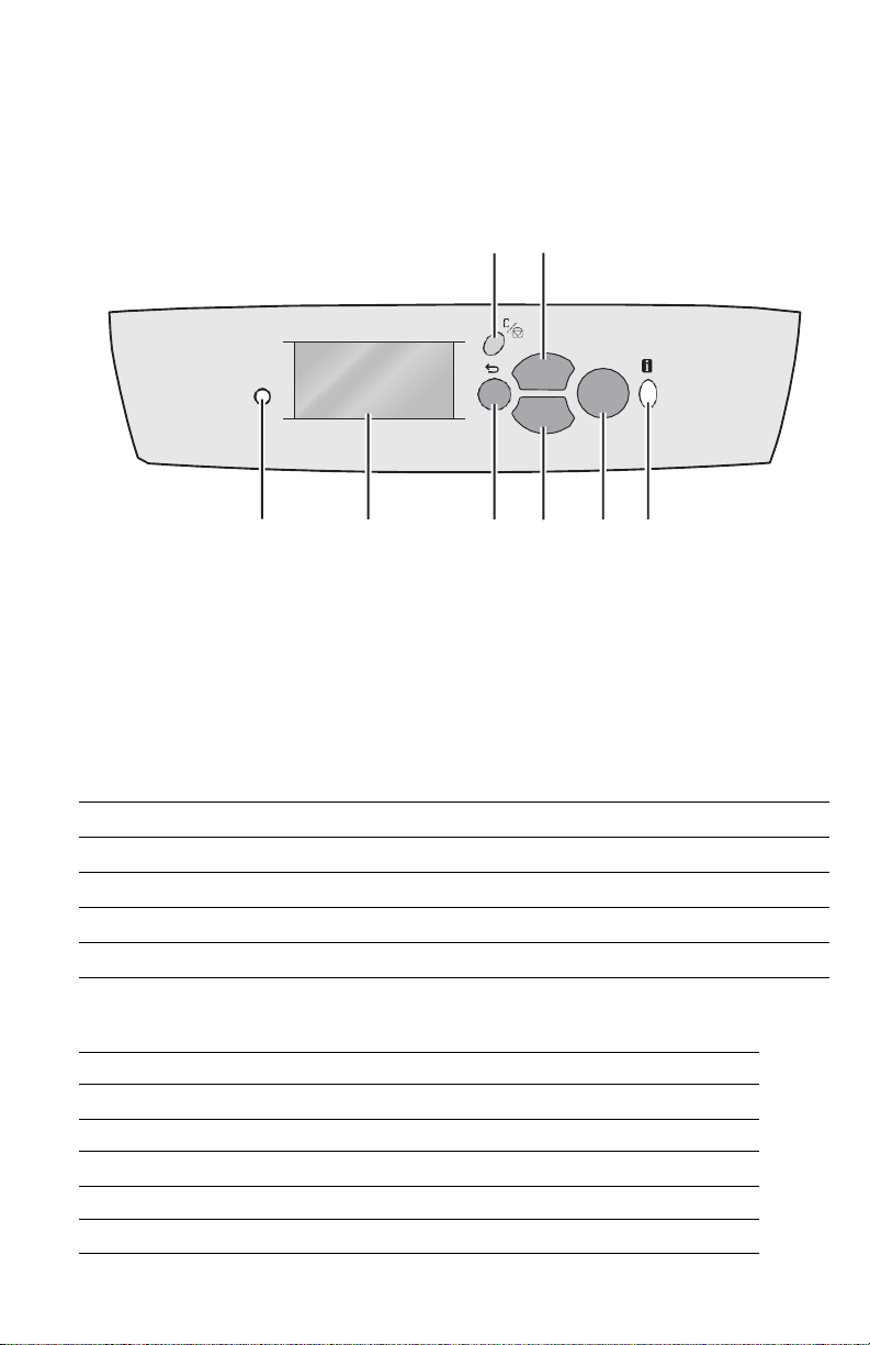
Front Panel
The Front Panel consists of one tricolor LED, a display window, and six functional
buttons.
3 5
1 2 4 6 7 8
s4500-003
1.
LED 5. Up Arrow button - scrolls up the menu system
2.
Graphic front panel display 6. Down Arrow button - scrolls down the menu system
3.
Cancel button 7. OK (select) button
4.
Back button 8. Information button - for additional explanation or help
LED States
LED State Printer State
Green Ready to Print or in Power Saver mode
Flashing Yellow Warning (but can still print)
Flashing Green In Standby mode or busy (receiving data, processing data, printing)
Flashing Red Error; cannot print
Front Panel Shortcuts
Mode Buttons Pressed at Power On
Skip execution of POST diagnostics OK
Print Service Diagnostics Map Information
Reset PostScript NVRAM Back + OK
Password Bypass Up Arrow + Down Arrow
Enter Service Diagnostics Back + Information
Phaser 4500
OK
Page 32

1-6
Phaser 4500 Service Manual
Image Processor Board
When installing a new Image Processor Board in the printer, you must transfer the
following parts from the old board:
■
Memory DIMMs
■
Hard Drive (if installed)
■
NVRAM
■
Configuration Card
1
6
2
3
7
4
8
5
5
9
1.
Memory (RAM) DIMM 1 and DIMM 2 6. Parallel connector
2.
Flash Memory (optional) 7. Ethernet connector
3.
Hard Drive (optional) 8. USB connector
4.
NVRAM connector 9. Health LED
5.
Configuration Card
Page 33

[Type here]
Transfer Roller
Feed Rollers
3 per paper tray
s4500-267
Fuser
s4500-268
Consumables and Routine Maintenance Items
Print Cartridge
Page 34

1-8
Phaser 4500 Service Manual
Supply Life Counters
Internal counters track the usage of the Consumables and Routine Maintenance Items
and store the values in NVRAM. The image processor board monitors these counters
in order to display the near end-of-life and end-of-life messages.
Print life ratings are based on 5% coverage and an average job length of 4 pages.
Supply Print Life (Number of Images)
Consumables
Print Cartridge, standard-capacity 10,000
Print Cartridge, high-capacity 18,000
Routine Maintenance Items
Maintenance Kit (consists of Fuser,
Transfer Roller, and 12 Feed Rollers)
200,000
Page 35

[Type here]
Printer Specifications
Physical Dimensions and Clearances
Print Engine Dimensions
Value
Height
404 mm (15.9 in.)
Width
422 mm (16.6 in.)
Depth
465 mm (18.3 in.)
Depth with Paper Cassette extended
524 mm (20.7 in.)
Weight (with 10-K Print Cartridge)
20.5 kg (45.2 lbs.)
Clearances
Value
Top
400 mm (16 in.)
Left
210 mm (8 in.)
Right
300 mm (12 in.)
Front
480 mm (19 in.)
Rear (with Duplex Unit installed)
230 mm (9 in.)
Total Height requirement
820 mm (32 in.)
Add 9.6 cm (3.75 in.) for each
550-Sheet Feeder
Mounting surface level tolerance
± 5°
550-Sheet Feeder Dimensions
Value
Height (to top of feeder assembly)
143 mm (5.6 in.)
Width
422 mm (16.6 in.)
Depth
452 mm (17.8 in.)
Depth with Paper Cassette extended
510.2 mm (20.1 in.)
Weight
6.3 kg (13.9 lbs.)
Duplex Unit Dimensions
Value
Height
218.5 mm (8.6 in.)
Width
352 mm (13.8 in.)
Depth
96 mm (3.8 in.)
Weight
1.9 kg (4.2 lbs.)
Page 36

1-10
Phaser 4500 Service Manual
Stacker Dimensions Value
Height 226 mm (8.9 in.)
Width 418 mm (16.4 in.)
Depth
Depth with Stacker Tray extended
312.5 mm (12.3 in.)
382.5 mm (15.1 in.)
Weight 2.6 kg (5.7 lbs.)
Functional Specifications
Characteristic Specification
Printing process: Recording System: Electrophotography (roller charging, magnetic
monocomponent toner development)
Exposure System: Semiconductor laser beam scanning
Transfer System: Roller transfer system
Fusing System: Thermal fixing using a heat roller
Resolution /
Addressability
600/1200 dpi
Print-Quality Modes Two choices: 600 x 600 dpi
True 1200 x 1200 dpi
Continuous Operating
Printing Speed
36 pages per minute for plain Letter paper, one-sided printing
34 pages per minute for A4 paper, one-sided printing)
21 images per minute for Letter paper, 2-sided printing
21 images per minute for A4 paper, 2-sided printing)
First Print-Out
Paper Size
Mode
Tray 1
Tray 2
Tray 3
Tray 4
from READY state
Letter
Simplex
8.7
8.7
8.7
8.9
(in seconds);
Duplex
12.5
12.5 12.5
12.8
Short Edge Feed
A4
Simplex
8.7
8.7
8.7
9.0
Duplex
12.7
12.7 12.7
13.0
First Print-Out
Paper Size
Mode
Tray 1
Tray 2
Tray 3
Tray 4
from Sleep Mode
Letter
Simplex
24.0
24.0 24.0
24.2
(in seconds);
Duplex
27.8
27.8 27.8
28.1
Short Edge Feed
A4
Simplex
24.0
24.0 24.0
24.3
Duplex
28.0
28.0 28.0
28.3
Warm-Up Time
17 seconds
Page 37

[Type here]
Electrical Specifications
Characteristic Specification
Primary Line Voltages 120 VAC nominal, min. 98 V, max. 140 V
220/240 VAC nominal, min. 198 V, max. 264 V
Primary Line Voltage
Frequency Range
50/60 Hz ± 3 Hz
Power Consumption 985 W @ 120 V
985 W @ 220/240 V
Environmental Specifications
Characteristic
Specification
Temperature:
Operating
5 to 35° C (41 to 95° F)
Transportation
-20 to 40° C (-4 to 104° F)
Humidity (%RH)
Operating
Transportation
15 to 85
5 to 85
Altitude
Operating
0 to 3,500 meters (11,500 feet)
Transportation*
0 to 15,000 meters (49,200 feet)
Acoustic Noise
LWA(B)
Engine only
With options
Idle
4.00 B —
Printing
6.62 B
7.30 B
* Air transportation in pressurized cargo space
ENERGY STAR qualified printer
Page 38

1-12
Phaser 4500 Service Manual
Media and Tray Specifications
Input Trays
Trays
Specifications
Printable
All
Within 4 mm of paper edge guaranteed.
Area Edge-to-edge printing supported.
Supported
Tray 1
Width: 76.2 mm (3.0 in.) ~ 215.9 mm (8.5 in.)
Media Sizes
Trays 2-4
Width: 98.4 mm (3.9 in.) ~ 215.9 mm (8.5 in.)
Tray 1
Length: 127.0 mm (5.0 in.) ~ 355.6 mm (14 in.)
Trays 2-4
Length: 148.0 mm (5.8 in.) ~ 355.6 mm (14 in.)
Supported
All
Bond 60-216 g/m2 (16-58 lb.)
Media Types
All
Labels
and Weights
All
All
Tray 1
All
All
Transparency
Greeting Cards 190 g/m2 (70 lb. Cover)
Index Card Stock 60-216 g/m2 (33-120 lb.)
Tag Card Stock 60-216 g/m2 (37-133 lb.)
Cover Card Stock 60-216 g/m2 (37-133 lb.)
Supported
All
#10 Commercial (4.12 x 9.5 in.)
Envelopes
Monarch (3.87 x 7.5 in.)
DL (110 x 220 mm)
C5 (162 x 229 mm)
B5 (176 x 250 mm)
Tray Capacity
Tray 1
150 sheets
Trays 2-4
550 sheets
Based on 75 g/m2 (20 lb.) paper stock.
Capacity is reduced for heavier/thicker stock.
Output Trays
Trays
Specifications
Supported
Standard
Width: 76.2 mm (3.0 in.) ~ 215.9 mm (8.5 in.)
Media Sizes
Stacker
Width: 90 mm (3.9 in.) ~ 216 mm (8.5 in.)
Standard
Length: 127.0 mm (5.0 in.) ~ 355.6 mm (14 in.)
Stacker
Length: 148.0 mm (5.8 in.) ~ 355.6 mm (14 in.)
Supported
Both
Bond 60-216 g/m2 (16-58 lb.)
Media Types
Labels
and Weights
Transparency
Greeting Cards 190 g/m2 (70 lb. Cover)
Index Card Stock 60-216 g/m2 (33-120 lb.)
Tag Card Stock 60-216 g/m2 (37-133 lb.)
Cover Card Stock 60-216 g/m2 (37-133 lb.)
Page 39

[Type here]
Output Trays (Continued)
Trays Specifications
Supported
Envelopes
Both #10 Commercial (4.12 x 9.5 in.)
Monarch (3.87 x 7.5 in.)
DL (110 x 220 mm)
C5 (162 x 229 mm)
B5 (176 x 250 mm)
Tray Capacity Standard
Stacker
500
500
Duplex Unit Media Specifications
Input Tray
Specifications
Width
Tray 1
90 - 216 mm (3.5 - 8.5 in.)
Trays 2-4
98 - 216 mm (3.9 - 8.5 in.)
Height
Tray 1
140 - 356 mm (5.5 - 14.0 in.)
Trays 2-4
148 - 356 mm (5.8 - 14.0 in.)
Supported
Media Types
and Weights
All
Bond 60-216 g/m2 (16-58 lb.)
Greeting Cards 190 g/m2 (70 lb. Cover)
Index Card Stock 60-216 g/m2 (33-120 lb.)
Tag Card Stock 60-216 g/m2 (37-133 lb.)
Cover Card Stock 60-216 g/m2 (37-133 lb.)
Memory Requirements
Characteristic Specification
Minimum required 64 MB – The Phaser 4500B configuration reports 48 MB
Maximum
supported
512 MB – accepts modules of 32, 64, 128, or 256 MB in
combinations to a total of 512 MB
Supported type PC133 SDRAM in 144-pin SO-DIMM form
Page 40

1-14
Phaser 4500 Service Manual
Page 41

[Type here]
Theory of
Operation
In this chapter...
■
Overview of the Phaser 4500 Laser Printer
■
Paper Path of the Printer
■
Sensors
■
Major Assemblies and Functions
■
Printer Options
Chapter
2
Page 42

Page 43

Page 44

2-2
Phaser 4500 Service Manual
Overview of the Phaser 4500 Laser Printer
Summary of the Printing Process
The Phaser 4500 print process consists of the following steps:
1.
Charge – The Print Cartridge contains a Bias Charge Roller that uniformly
distributes a negative electrical charge over the photoconductive drum surface.
2.
Exposure – The Laser Assembly scans the surface of the photoconductive drum,
which is located inside the Print Cartridge. The Laser Diode Assembly produces
a laser beam which is turned on and off according to a data signal. A 12-sided
polygonal mirror in the Scanner Assembly is rotated at a specified speed. The
laser beam is reflected off of the mirror and onto the drum surface through a
series of lenses and mirrors. The laser beam scans the drum surface from one end
to the other, neutralizing the negative charge to create one line of a latent image
on the surface. The drum is rotated and the scan process is repeated to form an
image on the drum surface.
3.
Development – A magnetic roller in the Print Cartridge carries a thin layer of
toner supplied by an agitator in the cartridge's toner compartment. The Charging
and Metering (CM) Blade inside the cartridge applies a negative charge to the
toner and spreads the toner onto the magnetic roller. The negatively charged toner
is transferred to the Areas of the drum surface that have been discharged.
4.
Paper Transport – Paper size sensors determine the length and width of the
media. Four tabs (one fixed, three movable) located in the paper tray indicate the
location of the length guide. Switches located in the left tray guides detect the
position of four tabs located on the paper tray. The Phaser 4500 uses a threeroller system to pick paper. Two springs raise the tray's lift plate, along with the
paper stack, against the pick roller of the paper feeder assembly. To pick paper,
the nudger roller advances the top sheet to the feed roller and retard roller. The
retard roller prevents multi-picks. The feed roller advances the paper to the turn
pinch rollers, which feed it to the registration rollers. The registration sensor is
the first sensor to detect paper.
5.
Transfer – The Transfer Roller is driven by a gear on the print cartridge. The
pressure of the Transfer Roller against the drum assists in driving the paper
through the transfer area. The Transfer Roller applies a positive charge to the rear
surface of the paper. The negatively charged toner image on the drum is attracted
to the positive charge on the rear surface of the paper, causing the image to be
transferred from the surface of the drum onto the paper.
6.
Discharge – The Detack Saw, located on the Transfer Roller assembly, helps to
separate the paper by partially neutralizing the charge holding the paper to the
drum. A cleaning blade in the Print Cartridge scrapes any remaining toner from
the surface of the drum. Then, the photoconductive drum is neutralized to prepare
the drum for the next print cycle.
7.
Fusing – The paper is driven into the fuser, which uses heat and pressure rolls to
melt and bond the toner onto the surface of the paper. Heat Roller fingers inside
the fuser peel off the leading edge of the paper from the Heat Roller to prevent
the paper from becoming wound around it. An exit sensor detects paper exiting
from the fuser.
Page 45

10
Two-sided
Printing
Paper Enters
Cleaning
8
Discharge
6 Transfer 5 Development
3
Exposure
2 Charge 1
9
Paper Exit
4
Paper
Transport
7
Fusing
8.
Cleaning – A cleaning blade in the Print Cartridge scrapes off toner remaining on
the drum surface after Transfer has occurred. Then, the latent charge pattern
remaining on the photoconductive drum is neutralized to prepare the drum for the
next Exposure cycle.
9.
Paper Exit – The paper is then advanced upward into the exit rollers and into the
selected output tray.
10.
Two-sided printing reverses the direction of the exit rollers to route the paper
through the Duplex Unit rollers and back to the registration roller. A sensor in the
Duplex Unit detects the presence of paper.
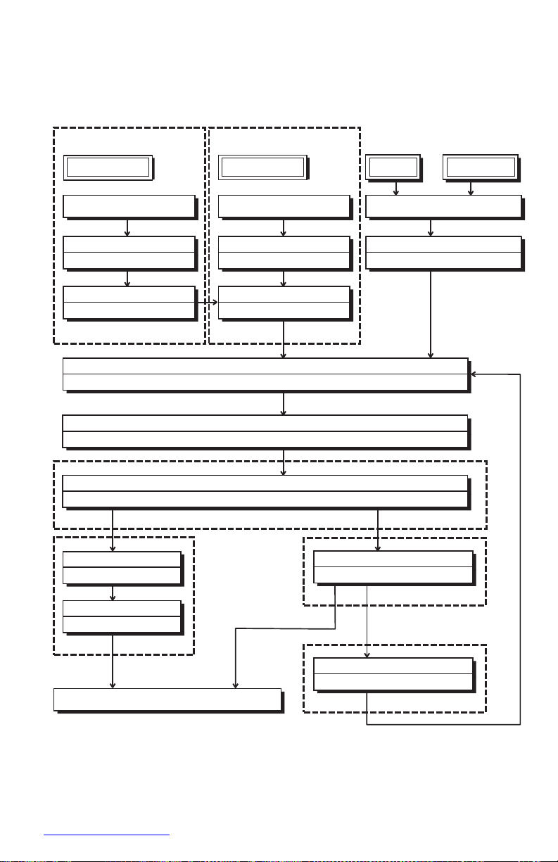
The block diagram of the Phaser 4500 print cycle shows the sequence of events for
the xerographic process (dashed lines) and the paper flow (solid lines) into and out of
the printer.
Block Diagram of the Print Cycle
s4500-007
Page 46

2-4
Phaser 4500 Service Manual
3. Development
Heat Roller
8. Cleaning
This cut-away side view of the Phaser 4500 printer shows the location of individual
components within the printer, and the major components that are directly related to
the print cycle and to the paper path.
Fuser Assembly
Cleaning
Blade
1.
Charging
Paper
Drum
BCR
2. Exposure
Laser Beam
Transport
Print Cartridge
Charge Metering Blade
Magnetic Roller
Paper
Components Associated with the Xerographic Process
s4500-008
5. Transfer
Detack Saw
Transfer Roller
6. Discharge
Pressure
Roller
7. Fusing
Page 47
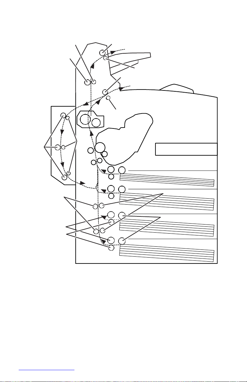
Paper Path of the Printer
Paper is supplied from Trays 1 and 2 or the optional Trays 3 and 4, and is transported
into the printer along the paper path shown below.
Optional 550-Sheet Feeder
(Tray 4)
Nudger Roller
Feed Roller
Retard Roller
Optional 550-Sheet Feeder
(Tray 3)
Nudger Roller
Feed Roller
Retard Roller
Tray 2 Tray 1
Nudger Roller
Feed Roller
Retard Roller
Turn Roller
Turn Pinch Roller
Turn Roller
Turn Pinch Roller
Rubber Registration Roller
Metal Registration Roller
Transfer Roller Assembly
Drum
Heat Roller
Pressure Roller
Fuser Assembly
Lower Stacker Roller
Pinch Roller
Upper Stacker Roller
Stacker Pinch Roller
Optional Stacker
Print Exit
Exit Roller
Exit Pinch Roller
500-sheet Exit Assembly
Duplex Roller
Pinch Roller
Optional Duplex Unit
s4500-017
550-Sheet Tray
550-Sheet Tray
Page 48

2-6
Phaser 4500 Service Manual
Layout of Paper Transport Path
This cross section of the Phaser 4500 printer shows the main components directly
associated with the paper path and transport in the engine only.
1
3
2
4
5
13
14
6
7
8
12
9
10
11
s4500-018
1.
Exit Roller 8. Rubber Registration Roller
2.
Exit Pinch Roller 9. Metal Registration Roller
3.
Fuser Assembly 10.Feed Roller Assemblies
4.
Pressure Roller 11.Retard Roller Assemblies
5.
Heat Roller 12.Nudger Roller Assemblies
6.
Drum 13.Print Cartridge
7.
Transfer Roller Assembly 14.Laser Assembly
Page 49
This cross section shows the additional components associated with paper transport
when the 550-Sheet Feeders, the Duplex Unit, and the Stacker are installed.
7
4500-019
1.
Stacker Pinch Roller 8. Pinch Rollers
2.
Lower Stacker Roller 9. Turn Pinch Rollers
3.
Upper Stacker Roller 10.Turn Roller Assemblies
4.
Pinch Roller 11.Feed Roller Assemblies
5.
Exit Roller 12.Retard Roller Assemblies
6.
Exit Pinch Roller 13.Nudger Roller Assemblies
7.
Duplex Rollers
1
3
2 5
4
6
8
9
10
13
11
12
Page 50

2-8
Phaser 4500 Service Manual
Sensors
The printer contains a number of sensors of various types that perform a variety of
functions. One group of sensors track the progress of the paper along the paper path,
and detect if a paper jam occurs. Other sensors detect the presence of the Print
Cartridge, stop printer activity if a door is open, and monitor the fusing temperature.
The basic printer has 18 sensors, while a fully-optioned printer has 30 sensors.
The types of sensors in use vary with their function. In general, there are four basic
type in use:
■
Photo
■
Microswitch
■
Soft Touch Sensors (STS)
■
Magnetic
Most of the photo sensors consist of a LED in one arm of a U-shaped holder, and a
photo-transistor in the other arm. When nothing is between the arms of the sensor,
light from the LED falls on the photo-receptor, turning it on. If the light is interrupted,
the photo-transistor turns off. The on- or off-state of the transistor is used as a signal.
The microswitches are used primarily as interlocks in the printer. They are in a
normally open state, and close when actuated. A bank of switches in a holder is used
for detecting the size of paper in use in a tray. Cams in the tray close the switches in
various combinations (see “Control of Paper Size” on page 2-18) to send a size signal
to the controller.
The Soft Touch Sensor has a known value of resistance whose sensitivity varies with
temperature.
The magnetic sensor detects the magnetic properties of the toner in the print cartridge.
A fifth sensor in use in the printer is the antenna used to communicate with the
CRUM in the print cartridge.
The list of Sensor and Interlocks that follows gives each sensor by its name, lists
which of the types it is, and briefly describes its function in the printer. The reference
column lists manual pages where illustrations show the location of the sensor.
List of Sensors and Interlocks
Name Type Function Reference
Paper low Mechanically
actuated photo
sensor
Detects low paper condition in
550-Sheet trays 2, 3, and 4
(there is no low-paper sensing
in tray 1).
page 2-11
page 2-17
Page 51

List of Sensors and Interlocks
Name
Type
Function
Reference
No paper
Mechanically
actuated photo
Detects no paper condition in
all trays.
Page 2-17
sensor
Paper size
Microswitch bank
Detects the presence of a tray
Page 2-17
switches
and the paper size setting of
the tray.
Page 2-44
Registration
Mechanically
Detects the paper as it
Page 2-11
sensor
actuated photo
reaches the registration rollers.
Page 2-17
sensor
Toner sensor
Magnetic sensor
Detects the presence of toner
in the Print Cartridge.
Page 2-17
Exit sensor
Mechanically
Detects paper as it leaves the
Page 2-25
actuated photo
fuser.
sensor
Stack Full sensor
Mechanically
actuated photo
Detects when the standard
output tray is full.
Page 2-29
sensor
Temperature
Soft Touch Sensor
Two of these monitor the
Page 2-25
sensor
temperature of the Heat Roller.
Rear Cover
Switch
Microswitch
Interrupts +24 V to the Main
Motor when the Rear Exit
Page 2-32
Cover is open; in series with
24 V Interlock.
24 V Interlock
Microswitch
Interrupts +24 V to the Main
Page 2-32
Motor when the Top Cover is
open; in series with Rear
Cover Switch.
Top Cover Switch
Microswitch
Interrupts INTERLOCK BEF to
Page 2-32
indicate the Top Cover is open.
Laser Interlock
Microswitch
Interrupts +5 V to Laser Diode;
in series with 5 V Interlock
Page 2-32
Switch.
5 V Interlock
Microswitch
Interrupts +5 V to Laser Diode.
Page 2-32
In series with Laser Interlock.
Start of scan
sensor
Photo
Detects the laser beam at the
start of a scan.
Page 2-22
Fuser
Thermostatic
Interrupt AC power to the
Page 2-25
Thermostats
switches
Fuser Heater in overtemp
condition; two switches in
series.
Page 52

2-
Phaser 4500 Service Manual
List of Sensors and Interlocks
Name
Type
Function
Reference
Stacker Rear
Cover Switch
Microswitch
Signals the HVPS/Engine
Logic board that the Stacker
Page 2-40
Rear Cover is open.
Stacker Sensor
Mechanically
Senses the presence of paper
Page 2-40
actuated photo
sensor
in the Stacker.
Stacker Offset
Mechanically
Senses the position of the
Page 2-40
Sensor
actuated photo
Stacker Offset Chute.
sensor
Duplex Unit
Switch
Microswitch
Signals the HVPS/Engine
Logic board that the Duplex
Page 2-36
Unit Rear Cover is open.
Duplex Unit
Mechanically
Detects the presence of paper
Page 2-36
Sensor
actuated photo
sensor
in the Duplex Unit.
Stacker full
Mechanically
Detects when the Stacker
Page 2-40
Sensor
actuated photo
Output Tray is full.
sensor
Optional Feeder
Paper Size Switch
Microswitch bank
Detects the presence of a tray
and the paper size setting of
Page 2-44
Assembly
the tray.
CRUM antenna
Inductive magnetic
Communicates with the Print
code reader
Cartridge CRUM.
Page 53

Sensors in the Paper Path
5
4
3
2
6
1
7
8
9
10
11
12
13
s4500-270
1.
Registration Sensor 8. Tray 2 No Paper Sensor
2.
Fuser Exit Sensor 9. Tray 2 Low Paper Sensor
3.
Output Tray Full 10.Tray 3 No Paper Sensor
4.
Stacker Sensor 11.Tray 3 Low Paper Sensor
5.
Stacker Full 12.Tray 4 No Paper Sensor
6.
Duplex Unit Sensor 13.Tray 4 Low Paper Sensor
7.
Tray 1 No Paper Sensor
Page 54

2-
Phaser 4500 Service Manual
Major Assemblies and Functions
The functions of the main components of the Phaser 4500 printer are described in the
following sections:
■
Paper Tray
■
Paper Feeder
■
Print Cartridge
■
Transfer Roller Assembly
■
Laser Assembly
■
Fuser
■
500-sheet Paper Exit
■
Drive
■
Electrical
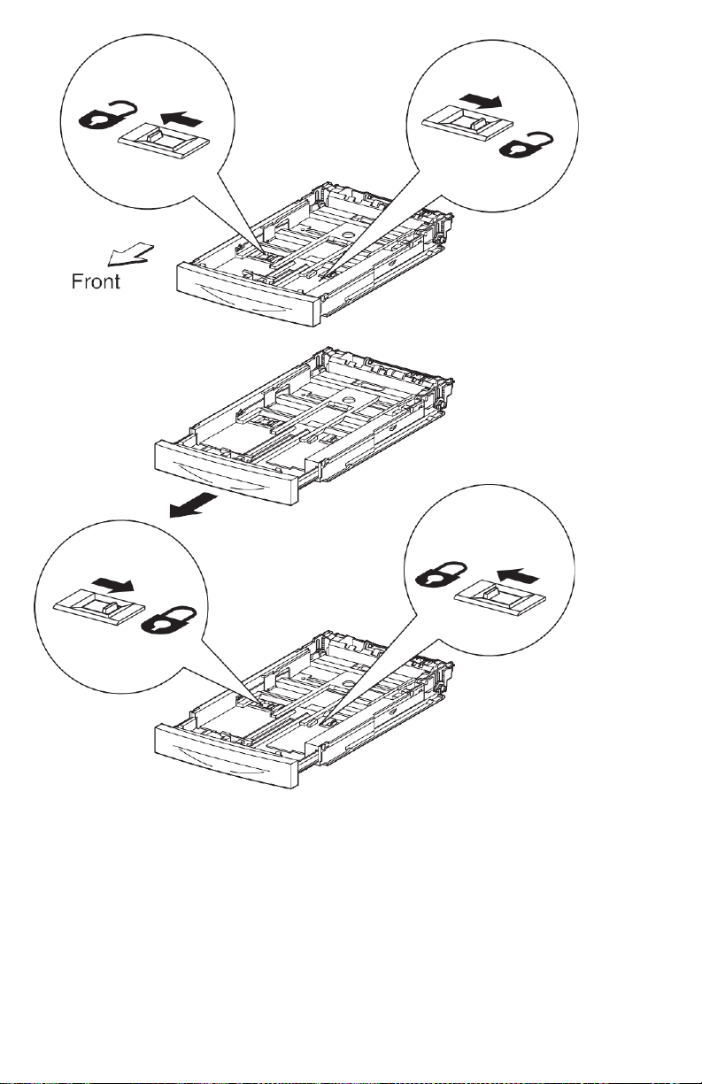
Paper Tray
Paper Trays include the 150-sheet tray and 550-sheet tray. Since they are functionally
equivalent, only the 150-sheet tray is described here.
The trays adjust to accept various paper sizes. The End and Side guides adjust to
match paper sizes shorter than A4, or narrower than Letter. To accept paper longer
than A4, the tray extension must be unlocked and pulled out, and the End and Side
Guides adjusted to match the size.
Page 55

2
1 3 4
5 7
6
Paper Tray Functional Assemblies
s4500-021
1.
Left-side Paper Guide Assembly 5. Right-side Paper Guide Assembly
2.
Bottom Plate Assembly 6. Extension Lock
3.
Bottom Lock Lever 7. End Guide
4.
Gear Stopper
Left- and Right-Side Paper Guide Assemblies The left and right Paper Guides
adjust to fit different paper widths. The guides hold the paper in position in the tray.
Bottom Plate Assembly The Bottom Plate Assembly is pushed up by the Bottom
Lift Spring. The bottom plate is released by unlocking the Bottom Lock Lever and
Stopper Gear. When the Bottom Plate Assembly is pushed up, the supplied paper
contacts the Nudger Roller.
Bottom Lock Lever and Gear Stopper These are at the rear of the tray (i.e., the
front end in the direction of travel of paper). How these components work is explained
in “Paper Lift Mechanism” on page 2-15.
Extension Lock The 150-Sheet Tray extends to accommodate different paper
lengths. The Extension Lock holds the extension in position.
Page 56
2-
Phaser 4500 Service Manual
s4500-020
End Guide The End Guide can be adjusted to different paper sizes by making a
forward or backward adjustment. It makes contact with the rear end of the paper, and
holds the paper in position front-to-back in the paper tray.
Through the cam action of the Sector Gear and Size Rack, the position of the End
Guide is converted to up and down combinations of the three Size Switch Links on
the side of the tray. The links, when in contact with the Paper Size Switches in the
Left Tray Guide, turn the switches on or off in combinations that correspond to the
paper size.
Page 57

The types of paper that can be automatically detected are as follows:
Type
Size (mm mm)
LETTER SEF
215.9 279.4
LEGAL 14" SEF
215.9 355.6
LEGAL 13" SEF
215.9 330.2
EXECUTIVE SEF
184.2 266.7
A4 SEF
210.0 297.0
B5 (JIS) SEF
182.0 257.0
A5 SEF
149.0 210.0
Paper Lift Mechanism
The Phaser 4500 printer paper trays utilize a unique mechanical paper lift mechanism
that eliminates the need for paper lift motors. The mechanism consists of a springloaded Bottom Plate Assembly that lifts the paper stack upward to the Paper Feeder
Assembly.
When the tray is removed from the printer, a channel in the Right Tray Guide pushes
the Bottom Lock Gear downward, lowering the Bottom Plate Assembly until it is
locked into place by a spring-loaded Gear Stopper, One-way Lock Gear, and the
Bottom Rack Lock. The Gear Stopper engages the Bottom Lock Gear, and the Bottom
Rack Lock engages the One-way Lock Gear, which prevents the Bottom Plate
Assembly from rising upward.
The Gear Stopper is released from the Bottom Lock Gear when the tray is inserted
into the printer. Once the Gear Stopper releases the Bottom Lock Gear, the Bottom
Rack Lock holds the Bottom Plate Assembly in place. Then, a metal tab located on
the Paper Feeder Assembly presses down on the Bottom Lock Lever. This releases the
Bottom Rack Lock and allows the Bottom Plate Assembly to raise the paper stack
upward until it contacts the Nudger Roller and lifts the feeder assembly.
Once the feeder assembly is lifted by the paper stack, the metal tab no longer contacts
the Lock Lever. As paper is fed from the stack, the feeder assembly gradually lowers.
When the tab contacts the Bottom Lock Lever, the paper stack raises. This process
repeats until the tray is empty.
Page 58

2-
Phaser 4500 Service Manual
Paper Feeder
Tray 1 and Tray 2 are functionally equivalent in terms of the Paper Size Switch
Assembly, No Paper Actuator, and No Paper Sensor. The component descriptions
given here apply to both trays.
Since the Low Paper Actuator and Low Paper Sensor are not part of Tray 1, the
description of these components applies to Tray 2 only.
150-Sheet/550-Sheet Feeder Assembly This mechanism moves paper from the
Paper Tray into the printer. The driving force from the Main Motor is transmitted via
the Feed Clutch Assembly to the Feed Roller and Nudger Roller, transporting paper
from the tray into the printer.
No Paper Actuator This actuator is kept in a raised position by the paper in the
tray. If the Paper Tray runs out of paper, the No Paper Actuator drops and the flag of
the No Paper Actuator moves from between the sensor arms, allowing the sensor to
turn on.
No Paper Sensor This is a photo sensor that remains in the OFF state when paper
is present in the tray. The sensor turns on when there is no paper in the tray and the
flag on the No Paper Actuator moves out of the sensor.
Registration Sensor The Registration Sensor is a photo sensor that detects paper
as it arrives at the Registration Rollers. The paper transported from the paper tray
pushes up the actuator of the Registration Sensor, moving the flag out of the sensor.
Registration Clutch This electromagnetic clutch turns on and off to drive the
Rubber and Metal Registration Rollers, which place the paper in position at the
appropriate time for transfer of the developed image from the drum.
Low Paper Actuator When paper is low in the Paper Tray installed in Tray 2, the
arm of the Low Paper Actuator is pushed up by the Bottom Plate Assembly, moving
the actuator flag out of the sensor. Low paper sensing occurs only in the 550-Sheet
Feeders, which includes Tray 2 and if installed, Trays 3, and 4.
Low Paper Sensor This photo sensor remains in an OFF state until the paper level
in the tray drops sufficiently to move the Low Paper Actuator flag out of the sensor.
Page 59
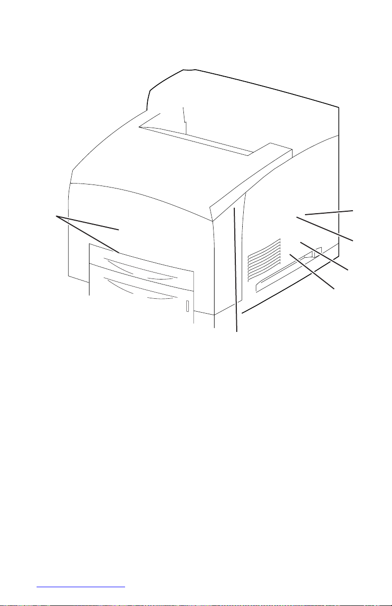
1
12
4500-022
1.
Paper Size Switch Assembly 7. Metal Registration Roller
2.
Feed Clutch Assembly 8. No Paper Sensor
3.
Registration Clutch 9. No Paper Actuator
4.
Rubber Registration Roller 10.Low Paper Sensor
5.
Feed Roller 11.Low Paper Actuator
6.
Registration Sensor 12.Nudger Roller
4
5 6
3
7
2
8
9
10 11
Page 60

2-
Phaser 4500 Service Manual
Control of Paper Size
Paper Size Switch Assembly The switches in this assembly send a signal that
indicates the paper size setting of the tray. Cams in the bottom of the tray are
positioned by the tray’s end guide. At pre-defined paper lengths, actuators on the side
of the tray close or open the switches in a pattern that is defined in the printer to
correspond to one of the pre-set media sizes.
The following table provides the ON (1) or OFF (0) states of the switches in the Paper
Size Switch Assembly, corresponding to the paper sizes of the Paper Tray.
Note
The switches in the Paper Size Switch Assembly are denoted by “SW1”, “SW2”,
“SW3”, and “SW4”, respectively, from the front side.
Paper size
Paper Size Switch Assembly
SW1
SW2
SW3
SW4
No cassette
0 0 0 0 Executive SEF
0 0 0 1 B5(JIS) SEF
0 0 1 1
A5 SEF
0 1 0 1
Legal14”SEF
0 1 1 1
Letter SEF
1 0 0 1
A4 SEF
1 1 0 1 Legal13”SEF
1 1 1 1
Page 61

Xerographics
Print Cartridge
The Print Cartridge is a customer-replaceable item that consists of the following
components:
Drum The Drum is an aluminum cylinder coated with a layer of photoconductive
material that retains electrical charges on its surface until exposed to light, when
electrical conduction occurs.
Bias Charge Roller (BCR) The BCR uniformly distributes electrical charges over
the drum surface, and erases a charge pattern remaining from the previous cycle.
Magnet Roller A thin layer of toner, supplied by the agitator in the toner
compartment, adheres to the surface of this roller, which transports the toner into the
gap between the drum and Magnet Roller.
Charging and Metering (CM) Blade The CM Blade spreads toner into a thin
layer over the Magnet Roller, and applies negative charges to the toner
triboelectrically.
Cleaning Blade The Cleaning Blade scrapes off toner remaining on the drum
surface after the transfer step.
Page 62

2-
Phaser 4500 Service Manual
1.
Print Cartridge 2. Transfer Roller
s4500-10
1
2
Page 63

Laser Assembly
The Laser Assembly scans the surface of the drum with a laser beam. The Laser
Assembly consists of three components: the Laser Diode (LD) Assembly, the Scanner
Assembly, and the Start of Scan (SOS) board.
Laser Diode (LD) Assembly The LD Assembly produces a laser beam that is
turned on and off according to the print data signal. A single LD is used for 600 dpi,
and a dual LD is used for 1200 dpi, generating one beam for 600 dpi and two beams
for 1200 dpi.
Scanner Assembly This assembly consists of a 12-sided polygonal mirror
mounted on the shaft of the scanner motor that reflects the beam to the drum surface
through lenses and mirrors, to scan the beam across the drum.
Start of Scan (SOS) Board When the laser beam strikes the sensor on the SOS
board, the signal generated indicates the initial position of the scan. The initial
position where a scan is started on each line is detected. Depending on the print
resolution selected, either one beam creates one line, or two beams create two lines at
a time.
When the laser beam scans from one end of the drum surface to the other while being
turned off and on, one line of a latent image is created. The resolution in the scanning
direction (from right to left) is determined by the rotational speed of the Scanner
Motor and by the speed at which the laser is modulated. The resolution in the process
direction (from top to bottom) is determined by the number of the scan beams and the
rotational speed of the print drum.
Page 64

2-
Phaser 4500 Service Manual
Conceptual Diagram of Image Creation by Scanning
Laser Assembly Functional Parts
s4500-011
1
3
2
s4500-012
1.
Start of Scan PWB 3. Laser Diode Assembly
2.
Scanner Assembly
Page 65

Laser Control
The scanner motor turns on when it receives a signal from the Controller, and turns
off after printing ends. The motor remains off in the standby and power-saving states.
There are two faults associated with the scanner motor speed: U2-1 Laser Fails at
warm-up, and U2-2, Laser Fails Motor Speed.
Two other Laser Unit faults, U2-3 and U2-4, are associated with LD power. U2-3
occurs when LD power is too high, and U2-4 occurs when LD power is too low.
Transfer Roller Assembly
The Transfer Roller is held in contact with the drum of the Print Cartridge, and is
driven by the Drum Gear. When the paper moves between the Transfer Roller and
Drum, the Transfer Roller applies a positive charge to the rear surface of the paper.
The negatively charged toner image is attracted by the positive charge on the rear
surface of the paper. Thus, the image is transferred from the surface of the drum to the
surface of the paper.
The Detack Saw, located on the Transfer Roller assembly, helps to separate the paper
from the drum surface.
Page 66

2-
Phaser 4500 Service Manual
Fuser
Heat Roller The Heat Roller is a metal tube with a coated surface and a Heater
Assembly inside. As paper passes between the Heat Roller and Pressure Roller, the
heat that is applied to the paper melts the toner and fuses it to the paper.
Pressure Roller The Pressure Roller is a metal shaft coated with sponge rubber. It
maintains pressure on the paper passing between it and the Heat Roller. This pressure
presses the melted toner against the paper.
Heater Assembly
The Heater Assembly consists of two halogen lamps located in the Heat Roller. One
lamp heats the entire length of Heat Roller, while the other, shorter rod heats the
center. The lamps are controlled by switching the neutral side of the power to each
lamp; the lamps use a common hot line.
Temperature Sensors These are Soft Touch Sensors (STS) having a known value
of resistance that varies with temperature. There are two Temperature Sensors in the
Fuser. One is located at the center of Heat Roller, the other is located where the edge
of a letter size sheet of paper comes through. The sensors monitor the temperature of
each location to control lighting of the Heater Rods. The sensors are mounted in
contact with the surface of the Heat Roller. Power to the Heater Rod is turned on and
off using the signals from these sensors, so that the surface temperature of the Heat
Roller can be maintained within a specified range. This signal is also used to provide
a first stage of overheat protection.
Thermostats The Thermostats are connected with the Heat Roller Assembly in
series, and provide a second level of overheat protection. If the first stage of overheat
protection does not prevent the Fuser from overheating, the Thermostats cut off the
power-supply circuit for the Heater Rod. If the paper type is set incorrectly, the
Pressure Roller may melt and adhere. As a countermeasure against this, if the STS
detect the higher temperature, but can not prevent the overheat, the Thermostats cut
power to prevent the Pressure Roller from melting and adhering.
Heat Roller Fingers These fingers peel off the leading edge of the paper from the
Heat Roller to prevent the paper from getting wound around the Heat Roller.
Heat Roller Diode The negative charge accumulated on the Heat Roller may
deteriorate the toner image on the paper during fixing. The Heat Roller Diode
discharges the charge to the frame ground.
Exit Sensor This sensor detects the arrival of the paper at a detection point in the
exit area positioned behind the Fuser. This sensor also detects the discharge of the
paper from this point. When the sensor receives light (i.e., paper is present), the signal
/EXIT is Low.
Page 67

1
2
3
4
5
6
7
s4500-023
1.
Exit Motor Assembly 5. Pressure Roller
2.
Exit Sensor 6. Heat Roller
3.
Actuator 7. Thermostats
4.
Temperature Sensors
Page 68

2-
Phaser 4500 Service Manual
Fuser Control
The fuser heater control maintains the fuser at a pre-determined control temperature
by turning the Halogen Lamp in the Heat Roller ON and OFF. The control
temperature varies depending on whether or not the printer is at the Ready state, and
whether the Main Motor is operating.
The fuser temperature is considered abnormal when the detected temperature exceeds
250 C, or falls below 130 C.
Temperature Control
At the start of warm-up and when the Main Motor is at rest, the standby temperature
is used as the Fuser control temperature. When the Main Motor is operating except at
warm-up, the running temperature is used as the Fuser control temperature.
Fuser Warm-Up
The Halogen Lamp is turned on when the Fuser warm-up begins. When the surface
temperature of the Heat Roller (detected by the Thermistor) reaches the Fuser control
temperature (standby temperature), the Fuser warm-up is ended.
Fuser Temperature Cycling
The Fuser temperature does not remain at a single, constant temperature, but varies
within a temperature range. There are several ranges, which are summarized in the
table. Except for the Standby mode, the mode is determined by the media type.
Mode
Temperature
Standby
Lamp ON 180° C
Lamp OFF 185° C
Normal
1-100 pages:
101-120 pages:
120 + pages:
Lamp ON 205° C
Lamp ON 205° C
Lamp ON 200° C
Lamp OFF 206° C
Temp. decreases by
.25° C per page
Lamp OFF 201° C
Thick Paper 1
Lamp ON 210° C
Lamp OFF 211° C
Thick Paper 2
Lamp ON 215° C
Lamp OFF 216° C
Transparency
Lamp ON 185° C
Lamp OFF 186° C
Page 69

Temperature Stabilization
The Fuser automatically enters a stabilization process under two circumstances:
■
When the printer is processing thick paper.
After 50 sheets of continuous printing on thick paper (Thick Paper 1 mode), the
Fuser lamp turns off, the Main Motor stops, and the fans rotate at full speed until
the temperature of both Temperature Sensors drops to 190° C or below. Then the
printer continues printing the job. The process for Thick Paper 2 is the same,
except that it occurs after 30 sheets of continuous printing on thick paper.
■
When the side Fuser Temperature Sensor (STS) detects an abnormally high
temperature (over 245° C).
When the side Fuser Temperature Sensor detects an abnormally high temperature
(over 245° C), the printer stops the print job and enters the following cool-down
process, which continues until the target Control Temperature of 180° C - 185° C
(Standby) is reached:
■
Clear the paper path of all paper
■
Continue to run the Main Motor (Time-out 200 sec.)
■
Run the Fans at full speed
■
Control Fuser temperature with Short Lamp
Fuser Problems (U4 Error Code)
Major causes of a U4 error include the following:
1.
Warm-up failure – Fuser warm-up not complete within 110 seconds after starting.
2.
Cool-down error – Cool-down process not complete within 200 seconds.
3.
Low Trouble temperature – The Fuser temperature drops to the Low Trouble
temperature (approximately current control temperature, minus approximately
25° C).
4.
High Trouble temperature – The Fuser temperature rises to the High Trouble
temperature (approximately current control temperature, plus approximately
35° C).
5.
STS circuit open
6.
STS failure – The Heat Rod remains on for at least 10 seconds after warm-up has
completed.
Page 70

2-
Phaser 4500 Service Manual
Power Shutoff to the Fuser
The printer shuts off power to the Fuser for the following reasons:
1.
Fuser abnormality (U4)
2.
Paper jam
3.
Cover Open — Top, Rear, Duplex Unit, Stacker
4.
Laser Assembly (ROS) abnormality (U2)
5.
CPU or NVRAM abnormality (U6)
6.
Main Motor Assembly abnormality (U1)
7.
Fan abnormality (U5)
8.
Fuser Pause command issued
9.
Xerographics failure
10.
Duplex Unit failure
11.
Stacker failure
12.
Option Tray Unit failure
Page 71
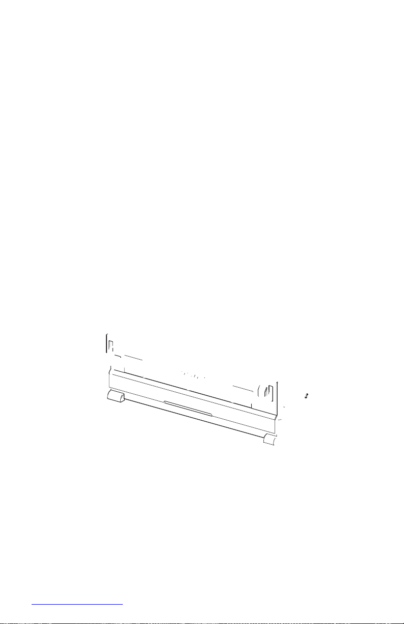
2 1
3 4
Paper Exit Assembly
The Paper Exit Assembly discharges the printed paper out of the printer, sending it
either to the standard output tray or to the optional Stacker.
Exit Motor Assembly This motor drives the Exit Roller that conveys paper to each
output tray. If the optional Duplex Unit is installed, this motor also reverses and
inserts paper into the Duplex Unit.
Exit Roller This roller transports the printed paper sent out from the Fuser, to the
standard output tray.
Stack Full Sensor This sensor detects that the standard output tray is full, using the
Stack Full Actuator.
Stacker Exit Gate This gate switches the paper transport path interlocking with the
Stacker Gate Link. When the Gate Solenoid Assembly installed in the optional
Stacker operates, the Stacker Gate Link pushed down by the spindle of the Solenoid
Assembly Gate blocks the normal paper output path and switches the output direction
to the Stacker output tray.
s4500-024
1.
Stack Full Sensor 3. Stacker Exit Gate
2.
Exit Roller 4. Exit Motor Assembly
Page 72

2-
Phaser 4500 Service Manual
Drive
Gear Assembly Housing The gears in this housing transmit power from the Main
Motor to various parts of the printer.
Gear Assembly Plate This transmits power from the Main Motor to the Print
Cartridge.
Link Lever This connects and disconnects the drive force from the Main Motor to
the Fuser Assembly. When the Top Cover is opened, the Link Lever pushes up the
Gear 8 in the Gear Assembly Housing disconnecting Gear 9 and thus, the Fuser
Assembly. As the Link Lever moves up and down, Gear 4 in the Gear Assembly Plate
moves right and left via Gear Link 3, and drive to the Print Cartridge Drum is
connected or disconnected.
4
s4500-025
1.
Main Motor 3. Gear Assembly Housing
2.
Gear Assembly Plate 4. Link Lever
3 2 1
Page 73

Electrical
24 V Interlock This safety switch interrupts 24 VDC from the LVPS to the HVPS/
Engine Logic Board and Main Motor when the Top Cover is open. This switch
operates in series with the Rear Cover Switch. See “Schematic Diagram of Power
Distribution and Interlocks” on page 2-33.
5 V Interlock This safety interrupts 5 VDC power from the LVPS to the LD
Assembly of the Laser Assembly when the Top Cover is open. This interlock works in
series with the Laser Interlock. See “Schematic Diagram of Power Distribution and
Interlocks” on page 2-33.
Rear Cover Switch This safety switch interrupts 24 VDC from the LVPS to the
HVPS/Engine Logic Board and Main Motor when the Rear Cover is open. This
switch operates in series with the 24 V Interlock. See “Schematic Diagram of Power
Distribution and Interlocks” on page 2-33.
Main Fan This vents air inside the printer to prevent an excessive rise in the inside
temperature.
Sub Fan This fan takes outside air into the printer to prevent an excessive rise in the
inside temperature. This is mounted near the Laser Assembly in the center on the
front side.
LVPS The Low Voltage Power Supply provides 5 V and 3.3 V for Logic Circuits, 5 V
for the Laser Diode, and 24 V for Motors and Clutches.
HVPS/Engine Logic Board The functions of the HVPS and engine controller are
brought together on a single circuit board. The HVPS provides high AC and DC
voltages to the BCR (charging), Magnet Roller (development), Transfer Roller
(transfer), and Detack Saw (peeling). The Engine Logic controls the printing
operation according to the information obtained through communications with the
Image Processor and from sensors and switches.
Image Processor Board This receives data from the Host Computer, performs
printing, and controls the whole printer.
Exit Motor PWBA This controls the Exit Motor Assembly according to a signal
from the HVPS/Engine Logic Board.
Interlock Switch Assembly This assembly consists of the following two safety
switches. See “Schematic Diagram of Power Distribution and Interlocks” on
page 2-33.
Top Cover Switch This safety interlock interrupts the INTERLOCK BEF signal
between the LVPS and the HVPS/Engine Logic Board to indicate that the Top
Cover is open.
Laser Interlock This safety switch interrupts 5 VDC from the LVPS to the LD
Assembly of the Laser Assembly when the Top Cover is open. This switch
operates in series with the 5 V Interlock.
Page 74

2-
Phaser 4500 Service Manual
DC-DC Converter The DC-DC Converter uses 24 V and 3.3 V from the LVPS to
supply 5 V and 3.3 V to the Image Processor Board. By using the 24 V, the DC-DC
Converter supplies additional power for the optional hard drive.
12
9
s4500-026
1.
LVPS 7. 5 V Interlock
2.
Exit Motor PWBA 8. 24 V Interlock
3.
Rear Cover Switch 9. Image Processor Board
4.
Laser Interlock 10.HVPS/Engine Logic Board
5.
Top Cover Switch 11.Sub Fan
6.
Main Fan 12.DC-DC Converter
4
5
3
7 8
6
2 1 10
11
Page 75
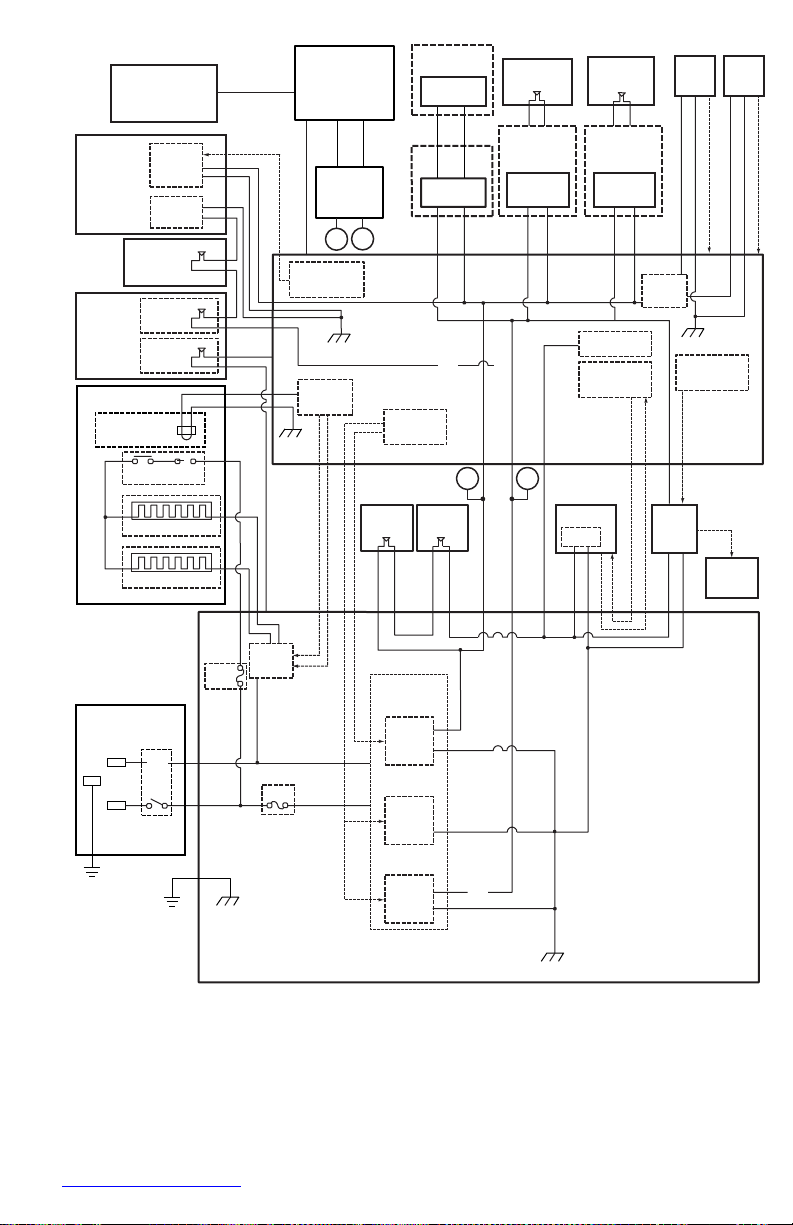
MAIN MOTOR ON
MAIN MOTOR ALM
3.3VDC
Front Panel
Image
Processor
Opt. 550-Sheet
Feeder
PWBA
Feeder 550
Duplex Cover
Open Switch
Rear Cover
Open Switch
Main Fan Sub Fan
Laser
Unit
5V
Interlock
Scanner
Motor
LDD
DC-DC
Converter
B A
Scanner Motor
Control
Opt. 550-Sheet
Feeder
PWBA
Feeder 550
24VDC
Optional
Duplex Unit
Duplex
PWBA
Optional
Stacker
Stacker
PWBA
Fan
Interlock
Switch
Laser
Interlock
Top Cover
SG
Fuse
3.3VDC
HVPS Circuit
Control
SG
Assembly
Switch
Fuser Assembly
Temperature
Sensor Assembly
Thermostat
TEMP.
L
5VDC
Fuser
Control
Power Save
Control
SG
A
B
Main Motor
Control
Exit Motor
Control
HVPS/
Engine
Logic
CRU A,CRU B, INA,INB
/INA,/INB
N
Heater Rod(850W)
N
Heater Rod(650W)
24V
Interlock
Rear Cover
Switch (24V)
Main Motor
Motor
Exit Motor
PWBA
A,B,/A,/B,
24VDC AFT
AC N
Power
Switch
Fuse
Heater
Control
Low Voltage
Generation
24VDC
Supply
LVPS
AC L
FG
Inlet
FG
Fuse
SG
5VDC
Supply
3.3VDC
Supply
Fuse
SG
Schematic Diagram of Power Distribution and Interlocks
s4500-027
Exit
Motor
INTERLOCK BEF
Data and Control
/HEAT ON (650W)
3.3VDC
5VDC
/HEAT ON (800W)
3.3VDC 3.3VDC
24VDC
24VDC
24VDC AFT
24VDC
24V D C
5VDC
3.3VDC
3.3VDC
24VDC
24VDC AFT
RTN
RTN
3.3VDC
24VDC
24VDC AFT
RTN
24VDC
RTN
FAN MAIN ALARM
24VDC
RTN
FAN SUB ALARM
Page 76

2-
Phaser 4500 Service Manual
Duplex Unit Motor
Idle Gear 67/29
Idle Gear 67/29
Roller Gear
Roller Gear
Idle Gear 49
Idle Gear 39
Idle Gear 29
Roller Gear
Printer Options
Three options are available for the Phaser 4500 printer:
■
Duplex Unit
■
Stacker
■
550-Sheet Feeder
Paper transport information for the options is discussed earlier in this chapter.
Duplex Unit
Drive Transmission Path
The rotating force of the Duplex Unit Motor is transmitted by various gears to
components requiring mechanical drive as shown in this flow chart and the gear
layout that follows.
s4500-028
Page 77
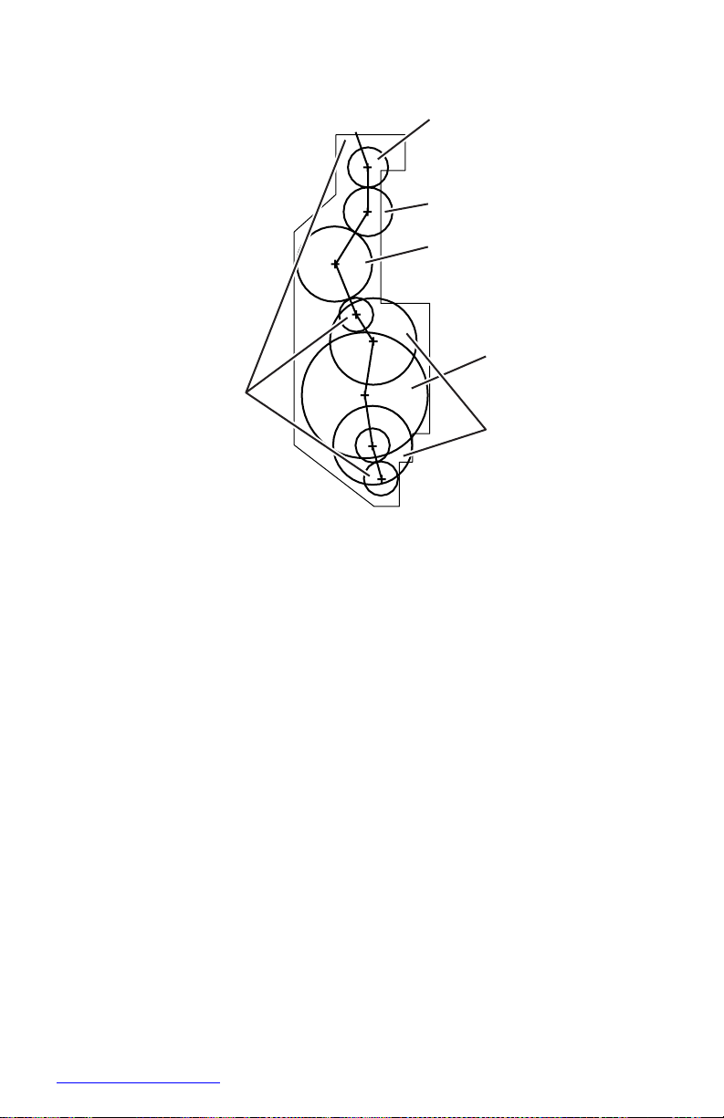
Gear Layout
5
1
6
s4500-029
1.
Roller Gears 4. Idle Gear 49
2.
Idle Gear 29 5. Duplex Unit Motor
3.
Idle Gear 39 6. Idle Gear 67/29
Functional Components
Two-sided printing is enabled by mounting the Duplex Unit on the rear side of the
base engine.
Duplex Unit Switch This switch detects that the Duplex Unit Lower Housing and
Duplex Unit Housing Cover are closed.
Duplex Unit Sensor This sensor detects the presence or absence of paper in the
Duplex Unit.
Duplex Unit Fan This fan vents air within the Duplex Unit and takes in outside air,
to prevent abnormal temperature rise in the Duplex Unit.
Duplex Roller This roller feeds the paper having the printed first surface back into
the printer through the Duplex Unit, to print on the second surface.
Duplex Unit PWBA The CPU on the Duplex Unit PWBA receives instructions
from the HVPS/Engine Logic Board and information from sensors and switches, and
controls paper transport through the Duplex Unit.
2
3
4
Page 78
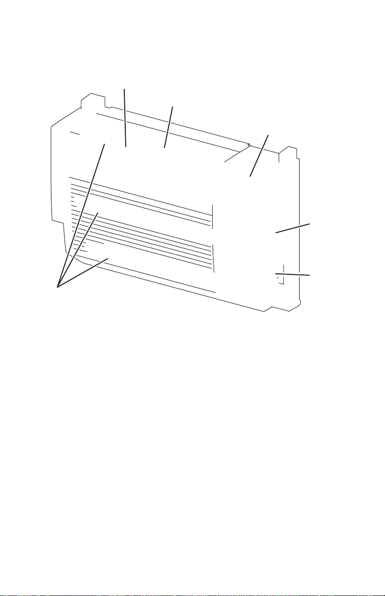
2-
Phaser 4500 Service Manual
Duplex Unit Motor This motor drives the three duplex rollers, which transport the
paper through the Duplex Unit.
2
5
6
s4500-030
1.
Duplex Unit Rollers 4. Duplex Unit PWBA
2.
Duplex Unit Sensor 5. Duplex Unit Switch
3.
Duplex Unit Fan 6. Duplex Unit Motor
3 4 1
Page 79
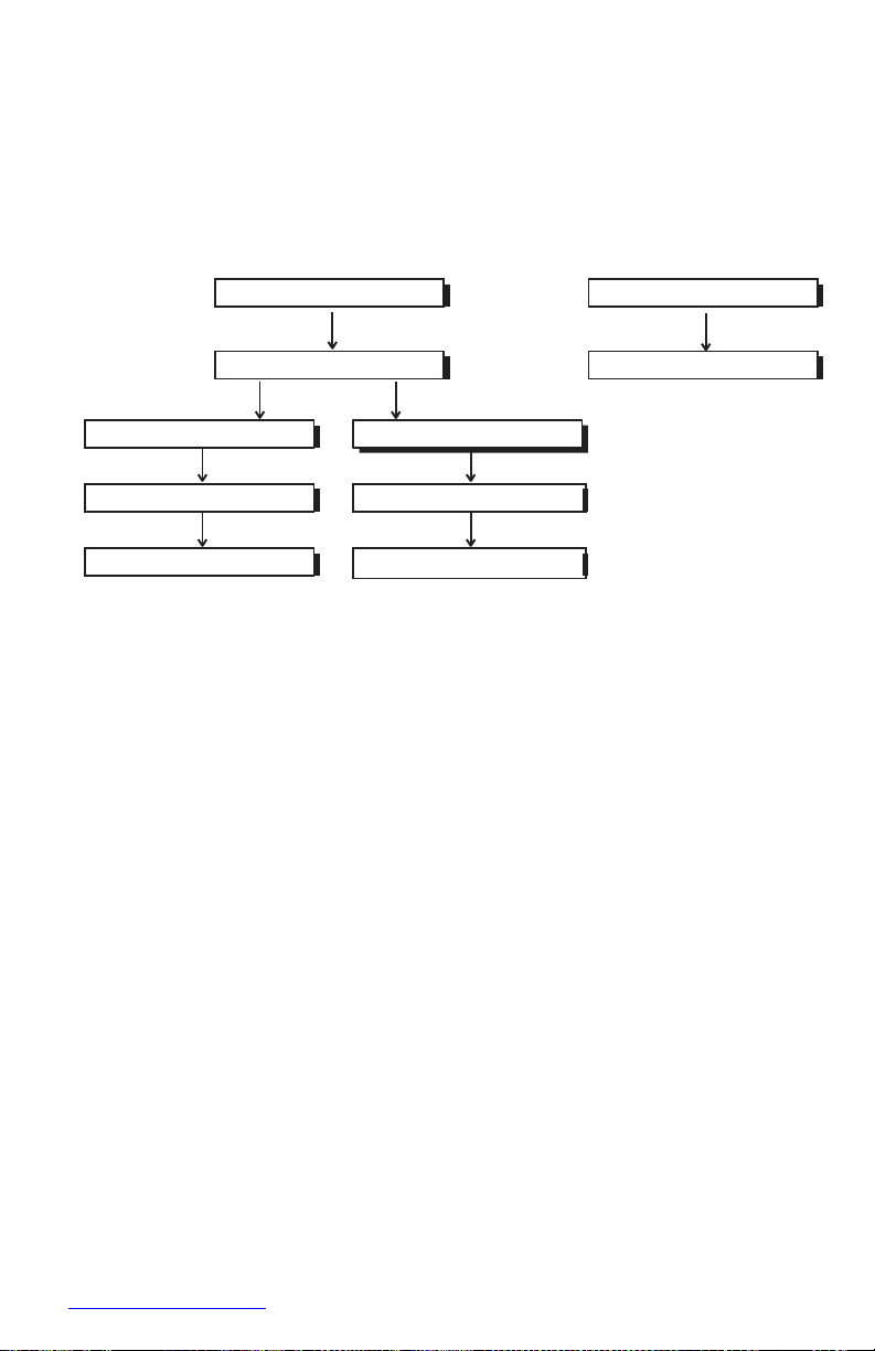
GEAR CAM
MOTOR ASSY OFFSET
ROLL OCT UPPER
ROLL OCT LOWER
GEAR 19
GEAR 19
GEAR 45
GEAR 45
GEAR 19/37
MOTOR ASSY OCT
Stacker
Drive Transmission Path
The rotating force of the Stacker Motor Assembly is transmitted by various gears to
components requiring mechanical driving force as shown in this flow chart and the
gear layout that follows.
s4500-031
Page 80
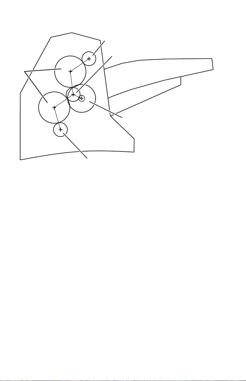
2-
Phaser 4500 Service Manual
2 3
1
4 5
Gear Layout
s4500-032
1.
Gear 45 4. Stacker Motor Assembly
2.
Gear 19 5. Gear 19
3. Gear 19/37
Paper Transport Path
When the Stacker is installed on the printer, the paper is transported as shown in the
illustration on page 2-7. The main components that transport paper through the
Stacker and shown in the diagram on page 2-5
Functional Components
Offset output is enabled by mounting the Stacker on top of the 500-Sheet Paper Exit.
Stacker Motor Assembly This motor drives the Lower Stacker Roller and Upper
Stacker Roller, which transport printed paper to the Stacker tray.
Offset Motor Assembly This motor drives the Offset Chute Assembly via the
Gear Cam.
Gate Solenoid Assembly This solenoid switches the output paper path between
the standard and Stacker paper output trays. When the Gate Solenoid Assembly
activates, the solenoid armature pushes the Stacker Gate Link to operate the Stacker
Exit Gate, which reroutes the paper to the Stacker paper output tray.
Page 81

Stacker PWBA The CPU on the Stacker PWBA receives instructions from the
HVPS/Engine Logic Board and information from sensors and switches, and controls
paper transport through the Stacker.
Stacker Rear Cover Switch This switch detects when the Stacker Rear Cover is
open.
Stacker Sensor This sensor detects the presence or absence of paper in the Stacker.
Stack Full Sensor This sensor is located on the Stacker PWBA, and detects when
the Stacker output tray is full, using the Stack Full Actuator.
Offset Sensor This sensor is located on the Stacker PWBA, and detects an offset
operation, using the Actuator in the Offset Chute.
Lower Stacker Roller This roller transports the printed paper coming out of the
Fuser to the Upper Stacker Roller.
Upper Stacker Roller This roller discharges the printed paper sent from the Lower
Stacker Roller into the Stacker paper output tray.
Offset Chute Assembly This assembly is driven by the Offset Motor Assembly
and Cam Gear to move right and left during paper output to offset the output of the
printer.
Page 82
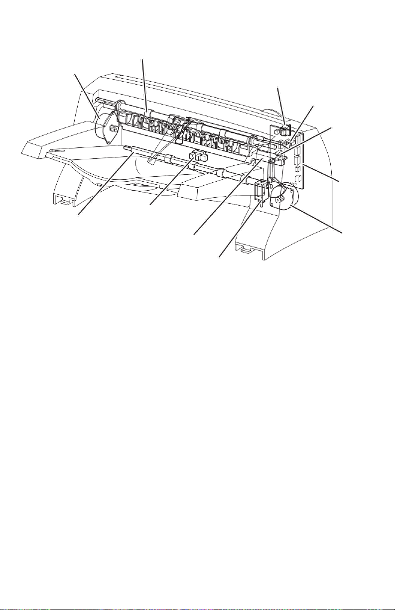
2-
Phaser 4500 Service Manual
2
1
3
4
5
6
10
11
9
7
8
s4500-033
1.
Stacker Motor Assembly 7. Offset Motor Assembly
2.
Upper Stacker Roller 8. Gate Solenoid Assembly
3.
Rear Cover Switch 9. Offset Chute Assembly
4.
Full Stack Sensor 10.Stacker Sensor
5.
Offset Sensor 11.Lower Stacker Roller
6.
Stacker PWBA
Page 83

Feeder Motor
Optional Feeder Gear 2
Optional Feeder Gear 3
Optional Feeder Gear 4
Optional Feeder Gear 5
Feed Clutch Assembly
Optional Feeder Gear 6
Pre-Registration Clutch
Optional 550-Sheet Feeder
Drive Transmission Path
The rotating force of the Feeder Motor is transmitted by various gears to components
requiring mechanical driving force as shown in this flow chart and the gear layout that
follows.
s4500-034
Page 84

2-
Phaser 4500 Service Manual
Gear Layout
2
3
4
1
5
8
6
7
s4500-035
1.
Optional Feeder Gear 6 5. Feeder Motor
2.
Turn Roller Clutch 6. Optional Feeder Gear 2
3.
Feed Clutch 7. Optional Feeder Gear 3
4.
Optional Feeder Gear 4 8. Optional Feeder Gear 5
Functional Components
The Paper Tray used in the optional feeder is identical to the 550-Sheet Paper Tray
used by the base engine, so the description of the Paper Tray is omitted here.
Option Paper Size Switch Assembly A bank of switches for setting the size of
paper supplied from each Paper Tray is mounted in the Left Tray Guide. A signal
indicating the paper size is transmitted as a voltage to the HVPS/Engine Logic Board.
No Paper Actuator This actuator is kept in a raised position by the paper in the
tray. If the Paper Tray runs out of paper, the No Paper Actuator drops and the flag of
the No Paper Actuator moves from between the sensor arms, allowing the sensor to
turn on.
No Paper Sensor This is a photo sensor that remains in the OFF state when paper
is present in the tray. The sensor turns on when there is no paper in the tray and the
flag on the No Paper Actuator moves out of the sensor.
Low Paper ActuatorWhen paper is low in the Paper Tray, the arm of the Low
Paper Actuator is pushed up by the Bottom Plate Assembly, moving the actuator flag
out of the sensor.
Low Paper SensorThis photo sensor remains in an OFF state until the paper level
in the tray drops sufficiently to move the Low Paper Actuator flag out of the sensor.
Page 85

Optional 550-Sheet Feeder This is a mechanism for supplying paper from the
paper tray into the printer. The driving force from the Feeder Motor is transmitted via
the Feed Clutch Assembly to the Feed Roller and Nudger Roller, transporting paper
from the tray into the printer.
As the Nudger Roller picks up paper and the paper level lowers, the position of the
Nudger Roller drops accordingly. The lowered Nudger Roller pushes down the lock
lever of the Bottom Plate Assembly, releasing it. The spring below the Bottom Plate
Assembly pushes it up and lifts the paper, which lifts the Nudger Support Assembly
off of the lock lever of the Bottom Plate Assembly stopping its upward motion.
Turn Roller This roller, working with the Turn Pinch Roller, advances the paper
picked by the Nudger and Feed Rollers into the printer. The Feeder Motor drives the
Turn Roller through the Turn Roller Clutch.
550-Sheet Feeder PWBA A CPU installed in the 550-Sheet Feeder PWBA
receives instructions from the HVPS/Engine Logic Board and from sensors and
switches; the CPU controls feeding operation in the 550-Sheet Feeder.
Page 86

2-
Phaser 4500 Service Manual
2
s4500-036
1.
Optional 550-Sheet Feeder 5. Low Paper Sensor
2.
Turn Roller 6. Low Paper Actuator
3.
No Paper Actuator 7. 550-Sheet Feeder PWBA
4.
No Paper Sensor 8. Option Paper Size Switch Assembly
1 3 4 5
6
8 7
Page 87

Error Messages
and Codes
In this chapter...
■
Introduction
■
Servicing Instructions
■
Entry Level Fault Isolation Procedure
■
Service Diagnostics
■
System Start-Up and POST
■
Operating System and Application Problems
■
Error Messages and Codes Troubleshooting Procedures
■
Inoperable Printer
Chapter
3
Page 88

Page 89

3-2
Phaser 4500 Service Manual
Introduction
This chapter covers troubleshooting procedures for problems in the Phaser 4500 that
generate error messages or fault codes or both that appear on the Front Panel or in the
Service Usage Profile report, and serves as the entry point into the troubleshooting
process. Troubleshooting of problems not directly indicated by or associated with an
error message or fault code is covered in “General Troubleshooting” on page 4-1.
Print quality problems are covered in “Print-Quality Troubleshooting” on page 5-1.
Servicing Instructions
This set of instructions is an overview of the path a service technician should take,
using this manual, to service the print engine and options. If you choose not to use the
instructions, it is recommended that you start at the appropriate troubleshooting table
and proceed from there.
Always follow the safety measures detailed in “Service Safety Summary” on
page xvii when servicing the printer.
Step 1: Identify the Problem:
1.
Verify the reported problem does exist.
2.
Check for any error codes and write them down.
3.
Print normal customer prints and service test prints.
4.
Make note of any print-quality problems in the test prints.
5.
Make note of any mechanical or electrical abnormalities present.
6.
Make note of any unusual noise or smell coming from the printer.
7.
Print a Service Usage Profile, if the printer is able to print.
8.
View the Engine Error and Jam Histories under the Service Tools Menu
9.
Verify the AC input power supply is within proper specifications by measuring the
voltage at the electric outlet while the printer is running.
Page 90

Error Messages and Codes
4you.com
Step 2: Inspect and Clean the Printer:
1.
Switch OFF printer power.
2.
Disconnect the AC power cord from the wall outlet.
3.
Verify the power cord is free from damage or short circuit and is connected properly.
4.
Remove the Print Cartridge and protect it from light.
5.
Inspect the printer interior and remove any foreign matter such as paper clips,
staples, pieces of paper, dust or loose toner.
6.
Do not use solvents or chemical cleaners to clean the printer interior.
7.
Do not use any type of oil or lubricant on printer parts.
8.
Use only an approved toner vacuum.
9.
Clean all rubber rollers with a lint-free cloth, dampened slightly with cold water and
mild detergent.
10.
Inspect the interior of the printer for damaged wires, loose connections, toner
leakage, and damaged or obviously worn parts.
11.
If the Print Cartridge appears obviously damaged, replace with a new one.
Step 3: Find the Cause of the Problem:
1.
Use the Error Messages and Codes and troubleshooting procedures to find the
cause of the problem.
2.
Use Service Diagnostics to check the printer and optional components.
3.
Use the Wiring Diagrams and Plug/Jack Locator to locate test points.
4.
Take voltage readings as instructed in the appropriate troubleshooting procedure.
Step 4: Correct the Problem:
1.
Use the Parts List to locate a part number
2.
Use the FRU Disassembly procedures to replace the part.
Step 5: Final Checkout
Test the printer to be sure you have corrected the initial problem and there are no
additional problems present.
Page 91

Page 92

3-4
Phaser 4500 Service Manual
Using the Troubleshooting Procedures
1.
Each Step in a Troubleshooting Procedure instructs you to perform a certain
action or procedure. Follow the steps sequentially in the order given until the
problem is fixed or resolved.
2.
The Actions and Questions box contains additional information and/or
additional procedures you must follow to isolate the problem.
3.
When a procedure instructs you to test a component using service diagnostics,
see “Service Diagnostics” on page 3-9 for the detailed steps and functions for
testing parts of the printer.
4.
The action is followed by a question. If your response to the question is “Yes”,
then follow the instructions for a “Yes” reply. If your response to the question is
“No”, then follow the instructions for a “No” reply.
5.
Troubleshooting Procedures frequently ask you to take voltage readings or test
for continuity at certain test points within the printer. For detailed diagrams, see
chapter 10, “Wiring Diagrams” on page 10-1 for complete information on test
point locations and signal names.
6.
Troubleshooting Procedures often ask you to replace a printer component.
Chapter 8 “FRU Disassembly” on page 8-1 provides detailed steps for removing
and replacing all major parts of the printer. Chapter 9, “Parts Lists” on page 9-1
details the location and part number for all spared parts of the printer.
General Notes on Troubleshooting
1.
Unless indicated otherwise, the instruction “switch ON printer main power”
means for you to switch ON printer power and let the printer proceed through
POST to a ‘Ready’ condition.
2.
When instructed to take voltage, continuity or resistance readings on wiring
harness, proceed as follows; Check P/J 232–1 to P/J 210–5 by placing the red
probe (+) of your meter on pin 1 of P/J 232, and place the black probe (–) of your
meter on pin 5 of P/J 210.
3.
When you are instructed to take resistance readings between
“P/J 232 <=> P/J 210” (without specified pin numbers), check all pins. See
“Wiring Diagrams” on page 10-1 for the location of all wiring harnesses and
pins.
4.
When you are instructed to take a voltage reading, the black probe (–) is
generally connected to a pin that is either RTN (Return) or SG (Signal Ground).
You can substitute any RTN pin or test point in the printer, and you can use FG
(frame ground) in place of any SG pin or test point. To locate connectors or test
points, see “Wiring Diagrams” on page 10-1 for more information.
5.
Before measuring voltages make sure the printer is switched ON, the Print
Cartridge and the paper trays are in place, and the interlock switches are actuated,
unless a troubleshooting procedure instructs otherwise.
6.
All voltage values given in the troubleshooting procedures are approximate
values. The main purpose of voltage readings is to determine whether or not a
component is receiving the correct voltage value from the power supply and if
Page 93

Error Messages and Codes
4you.com
gating (a voltage drop) occurs during component actuation. Gating signals may
be nothing more than a pulse, resulting in a momentary drop in voltage that may
be difficult or impossible to read on the average multi-meter.
Unless otherwise specified, the following voltage tolerances are used within this
section:
Stated Measured
+3.3 VDC +3.135 to +3.465 VDC
+5.0 VDC +4.75 to +5.25 VDC
+24.0 VDC +21.6 to +26.4 VDC
0.0 VDC Less than +0.5 VDC
7.
When a troubleshooting procedure instructs you to replace a non-spared
component and that component is part of a parent assembly, you should replace
the entire parent assembly.
Page 94

3-6
Phaser 4500 Service Manual
Accessing Fault Histories
■
Print (if possible) the Service Usage Profile.
a.
At the printer’s front panel, go to the Troubleshooting Menu and select
Service Tools.
b.
From the Service Tools menu select Service Usage Profile. The fault
histories are detailed in this report log.
Or...
■
View the printer’s fault history on the front panel.
■
Go to Troubleshooting Menu --> Service Tools --> Engine Error
History or Jam History.
Interpreting Fault History Error Codes
The following tables provide a cross-reference of the numeric fault history codes to
the diagnostic codes that appear on the Front Panel and in error messages. These
numeric codes are displayed on the Front Panel for both Engine Errors and Jams; in
the Service Usage Profile, the numeric codes are used only in the Engine Error Log
(Item 262).
Fault History Codes for Engine Errors
Fault
History
Code
Error
Fault
History
Code
Error
0 Fan Failure (U5)
5 Laser Failure (U2)
1 Fuser Failure (U4)
6 Tray 3 Failure (E11-1)
2 Motor Failure (U1)
7 Tray 3 or 4 Failure
(E11-2) 3
IOT NVM Failure (U6)
8 Duplex Failure (E9-1)
4 Stacker Failure (E9)
— —
Page 95

Error Messages and Codes
4you.com
On the Front Panel, the Jam History lists a series of entries separated by semi-colons.
Each entry is made up of two values separated by a comma: the first value is the
numeric Fault History Code for the Jam Location, and the second value is the engine
page count. An entry of 5,132 would mean that a Jam at Exit occurred at page count
132.
Fault History Codes for Jams
Fault
History
Code
Service Usage Profile Log Reports
Last Jam Location (Item 291)
Jam Code (Item 298)
1 Jam at Tray 1
E2-01, E2-02, E2-11
2 Jam at Tray 2
E2-02, E2-12
3 Jam at Tray 3
E2-03, E2-13
4 Jam at Tray 4
E2-04, E2-14
5 Jam at Exit
E4-0, E4-2, E4-3
6 Jam at Top
E3-1, E3-2
7 Jam at Duplex
E7-0, E7-1, E7-2, E7-3
8 Jam at Rear
E6-1
9 Jam at Stacker
E6-2
10
Paper Size Jam
PSE-1
Page 96

3-8
Phaser 4500 Service Manual
Entry Level Fault Isolation Procedure
Use this procedure to quickly determine the general area of the printer in which the
problem is located.
Troubleshooting Procedure
Steps Actions and Questions
Yes
No
1
Switch the printer OFF then ON.
Does the printer display READY TO
PRINT on the Front Panel Within 1
minute?
Go to Step 4
Go to step 2
2
Does the printer display an error
message or code?
Go to the
procedure for that
Go to step 3
error message or
code.
3
Is the Front Panel LCD/LED Display
defective, or the buttons inoperable?
Go to Front Panel
Troubleshooting
Go to step 4
procedure
4
Run Test Prints from all input trays:
1.
In the Main Menu, select
Troubleshooting and press the OK
button.
Go to the
procedure for that
error message or
code.
Go to step 5
2.
Select Print Quality Problems and
press the OK button.
3.
Select Test Prints and press the OK
button.
Does the printer display an error
message or code while printing?
5
Does the printer produce the test
prints?
Go to step 6
Go to step 7
6
Evaluate the test prints.
Does the print quality meet or exceed
Go to step 8
Go to “PrintQuality
the print quality specifications?
Troubleshooting”
on page 5-1
7
Enter Service Diagnostics and generate
Go to “Image
Go to “Inoperable
Print Engine Test Prints from all input trays.
Processor
Printer” on
Does the printer produce the test
Isolation” on
page 3-70
prints?
page 4-37
8
Request the customer to send a print job
Problem solved;
Go to “Operating
from their application.
return to Final
System and
Did the job print successfully?
Checkout in the
Application
Service Flowchart.
Problems” on
page 3-20
Page 97

Error Messages and Codes
4you.com
Service Diagnostics
The Phaser 4500 Laser Printer has built-in diagnostics to aid in troubleshooting
problems with the printer. The Service Diagnostics Menu provides a means to test
sensors, motors, switches, clutches, fans and solenoids. Diagnostics also contain
built-in test prints, printer status and some NVRAM access.
Service Diagnostics are to be executed through the front panel by a certified service
technician only. Service Diagnostics can be entered one of two ways:
Entering without rebooting the printer:
1.
From the printer’s main menu, scroll to Troubleshooting and press the OK
button, then scroll to Service Tools and press the OK button.
2.
Hold down both the Up and Down arrow buttons for about three seconds. When
the hidden Service Diagnostics menu appears, scroll to Run Service
Diagnostics and press the OK button.
Entering by rebooting the printer:
1.
Turn the printer power OFF.
2.
Hold down the Back and Information buttons simultaneously and turn the
printer back ON.
3.
Continue to hold the buttons until the following message is displayed on the front
panel: Entering Service Diagnostics, and then release the buttons.
4.
The front panel displays the Service Diagnostics Menu.
You can print a Service Diagnostics Menu Map by highlighting Print Service
Menu Map, and pressing the OK button. The printer will run through POST and
return to Ready. You will need to re-enter service diagnostics. The Service
Diagnostics Menu Map is also available in the Appendix on page A-4.
Page 98

3-10
Phaser 4500 Service Manual
Service Diagnostic Front Panel Button Descriptions
Button Function
BACK Returns to the prior higher level menu structure, if available.
If help text is displayed on the front panel, pressing BACK will restore the current
menu item and remove the help text.
CANCEL Terminates the current test.
Cancels current INFO display.
INFO Provides help information, if available.
Pressing INFO again restores the current menu item and removes the help text.
UP Scrolls up one menu item within a menu list. This control does not ‘wrap’.
Used to increment data in tests requiring user input.
DOWN Scrolls down one menu item within a menu list.
This control does not ‘wrap’, the end of a menu list is designated by three
asterisks.
Used to decrement data in tests requiring user input.
OK Enters the highlighted menu. Executes the current test item.
Used to select a data value entered by the user.
Using Service Diagnostics
Most of the diagnostic tests are straightforward and require no additional explanation,
but there are some that require that specific conditions be met to achieve meaningful
results. These instructions cover each of the test groups, listing special instructions,
conditions, or other information necessary to successfully interpret the results of the
diagnostic tests.
General Status
The General Status tests provide information about the current status of the printer.
These values are read-only and cannot be changed. They are intended primarily for
manufacturing use, and are of very limited value to the service technician.
Engine ROM Version Lists the version number of the code stored in the Engine
ROM and its checksum value.
Engine Print Count Lists the printer’s life count, the number of prints made since
the printer’s activation. This page count is reset if the HVPS/Engine Logic Board is
replaced.
Engine Configuration Lists the configurations set for the Engine. This report is of
very limited use to the service technician; it is mainly intended for manufacturing use.
Print Resolution Reports the printer’s maximum resolution capability. Determined
at the time of manufacture.
Page 99

Error Messages and Codes
4you.com
Read Fuser Temperature Shows the current fuser temperature in degrees C.
Reports the fuser temperature only in the Standby mode.
Engine Test Print
You can use Engine Test Print (see “Engine Test Print” on page 6-4) to identify,
repair, and validate the operability of printer Xerographics and paper handling from
all paper sources, options, and output destinations.
Print Test Pattern Starts the print.
Input Tray Lets you select the tray used as paper source.
Output Tray Lets you select the output location.
Duplex Turns two-sided printing on or off if the Duplex Unit is installed.
Print Quantity Allows you to select the number of test prints to run. Use the OK
button to select which digit to change, use the UP or DOWN buttons to change the
value of the digit, and use the Back button to set the selection. If Duplex is set to ON,
the quantity selected indicates the number of two-sided prints.
Engine NVRAM Adjustments
These adjustments allow you to change printer settings that control the power of the
laser beam, and that control the registration of the image on the paper.
Laser Power Adjusts the power of the laser beam. Adjustment is done on a scale of
0-8, with 4 being the factory default.
Tray 1/2/3/4 Process Direction Adjusts the image registration in the process
direction on paper coming from one of the paper trays. Increasing or decreasing the
set value by one number moves the leading edge of the print area 0.5 mm closer to or
farther from the edge of the paper.
Tray 1/2/3/4 Scan Direction Adjusts the image registration in the scan direction
on paper coming from one of the paper trays. Increasing or decreasing the set value by
one number moves the side edge of the print area 0.5 mm closer to or farther from the
edge of the paper.
Duplex Process Direction Adjusts the image registration in the process direction
on paper coming from the Duplex Unit. Increasing or decreasing the set value by one
number moves the leading edge of the print area 0.5 mm closer to or farther from the
edge of the paper.
Duplex Scan Direction Adjusts the image registration in the scan direction on
paper coming from the Duplex Unit. Increasing or decreasing the set value by one
number moves the leading edge of the print area 0.5 mm closer to or farther from the
edge of the paper.
Page 100

3-12
Phaser 4500 Service Manual
Motors/Fan Test
Individually turns on each drive motor or fan. In each case except the Stacker Offset
Motor, the sound of the motor running is the indication that the item passed or failed
the test. In the case of the Stacker Offset Motor, the motion of the Offset Chute is the
indicator.
Duplex Motor (All tests) The test runs the motor about three seconds, then stops
it. The test runs the motor even when the Duplex unit is open or a printer cover is
open.
Exit Motor (All tests) The test runs the motor about three seconds, then stops it.
Print engine Top and Rear Covers must be closed and Print Cartridge must be
installed for the motor to run.
Main Motor The test runs the motor for one minute or until you press the Back
button to stop it. Print engine Top and Rear Covers must be closed and Print Cartridge
must be installed for the motor to run.
Fan Motor High Speed The test runs the Main and Sub Fans for about three
seconds, then returns them to low speed. The test runs with covers open.
Fan Motor Stop The test stops the Main and Sub Fans for about three seconds, then
turns them on again at low speed. The test runs with covers open.
Laser Scan Motor The test runs the motor about three seconds, then stops it. The
test runs with covers open.
Stacker Motor The test runs the motor about three seconds, then stops it. The test
runs with Print Engine covers open.
Stacker Offset Motor The test runs the motor to move the chute once in each
direction. The test runs with covers open.
Tray 3/4 Feed Motor The test runs the motor about three seconds, then stops it. The
test runs with Print Engine covers open. Attempting to test a tray that is not installed
results in an “Option Not Installed” message.
Main Motor + Clutch/Sol Tests
Runs the Main Motor and activates the clutch selected to test the drive.
Tray 1/2/3/4 Feed Tests the drive to the feeder in the selected tray.
Tray 3/4 Turn Roller Tests the drive to the Turn Roller in the selected tray.
Sensor Tests
Tests the functionality of sensors/switches/options by manually toggling the sensor or
switch, or by installing either the Duplex Unit or Stacker.
Top Cover Switch Tests the circuit (not just a single switch) affected by opening
the Top Cover. The Print Cartridge must be installed and the Rear Cover closed for
this test to be effective. Toggle the switch by opening and closing the Top Cover.
“Open” or “Closed” indications appear on the front panel.
 Loading...