

Page 1

Xerox DocuColor 2060
NPS/IPS
Installation Planning Guide
721P90520
Version 8.0
October 2002
Page 2

Xerox Corporation
701 S. Aviation Boulevard
El Segundo, CA 90245
©2002 by Xerox Corporation. All rights reserved.
Copyright protection claimed includes all forms and matters of copyrightable
material and information now allowed by statutory or judicial law or hereinafter
granted, including without limitation, material generated from the software
programs which are displayed on the screen, such as icons, screen displays,
looks, etc.
Printed in the United States of America.
Publication number: 721P90520
Xerox® and all Xerox products mentioned in this publication are trademarks of
Xerox Corporation. Products and trademarks of other companies are also
acknowledged.
Changes are periodically made to this document. Changes, technical
inaccuracies, and typographic errors will be corrected in subsequent editions.
Page 3

Table of contents
Safety . . . . . . . . . . . . . . . . . . . . . . . . . . . . . . . . . . . . . . . . . . . . . . . . . ix
Laser safety . . . . . . . . . . . . . . . . . . . . . . . . . . . . . . . . . . . . . . . . . . . . . . . .ix
Ozone information: U. S. only . . . . . . . . . . . . . . . . . . . . . . . . . . . . . . . . . . x
Operation safety: U. S. . . . . . . . . . . . . . . . . . . . . . . . . . . . . . . . . . . . . . . . x
Operation safety: Europe . . . . . . . . . . . . . . . . . . . . . . . . . . . . . . . . . . . . .xi
Warning markings . . . . . . . . . . . . . . . . . . . . . . . . . . . . . . . . . . . . . .xi
Electrical supply . . . . . . . . . . . . . . . . . . . . . . . . . . . . . . . . . . . . . . xii
Ventilation . . . . . . . . . . . . . . . . . . . . . . . . . . . . . . . . . . . . . . . . . . . xii
Operator accessible areas . . . . . . . . . . . . . . . . . . . . . . . . . . . . . . xii
Maintenance . . . . . . . . . . . . . . . . . . . . . . . . . . . . . . . . . . . . . . . . .xiii
Before cleaning your product . . . . . . . . . . . . . . . . . . . . . . . . . . . . xiii
CE mark: Europe only . . . . . . . . . . . . . . . . . . . . . . . . . . . . . . . . . . . . . . . xiii
Radio and telecommunications equipment directive (Europe only) . . . .xiv
For further information . . . . . . . . . . . . . . . . . . . . . . . . . . . . . . . . . . . . . . . xv
Introduction . . . . . . . . . . . . . . . . . . . . . . . . . . . . . . . . . . . . . . . . . . xvii
About this guide . . . . . . . . . . . . . . . . . . . . . . . . . . . . . . . . . . . . . . . . . . . xvii
Contents . . . . . . . . . . . . . . . . . . . . . . . . . . . . . . . . . . . . . . . . . . . xvii
Conventions . . . . . . . . . . . . . . . . . . . . . . . . . . . . . . . . . . . . . . . . xviii
Notice . . . . . . . . . . . . . . . . . . . . . . . . . . . . . . . . . . . . . . . . . . . . . . . . . . .xix
1. System overview . . . . . . . . . . . . . . . . . . . . . . . . . . . . . . . . . . . . . . . 1-1
Functional overview of the NPS/IPS . . . . . . . . . . . . . . . . . . . . . . . . . . . 1-1
System component overview . . . . . . . . . . . . . . . . . . . . . . . . . . . . . . . . 1-2
NPS and IPS printing configurations . . . . . . . . . . . . . . . . . . . . . 1-2
NPS/IPS concurrent printing . . . . . . . . . . . . . . . . . . . . . . . . . . . . 1-3
SNMP support . . . . . . . . . . . . . . . . . . . . . . . . . . . . . . . . . . . . . . . . . . . . 1-3
IPP support . . . . . . . . . . . . . . . . . . . . . . . . . . . . . . . . . . . . . . . . . . . . . . 1-4
IPDS environment . . . . . . . . . . . . . . . . . . . . . . . . . . . . . . . . . . . . . . . . . 1-5
Host environments . . . . . . . . . . . . . . . . . . . . . . . . . . . . . . . . . . . 1-5
Channel interface board and channel cable con nector box—channel-
attached systems only . . . . . . . . . . . . . . . . . . . . . . . . . . . . . . . . 1-7
IPDS data stream . . . . . . . . . . . . . . . . . . . . . . . . . . . . . . . . . . . . 1-8
Network PDL printing environmen t . . . . . . . . . . . . . . . . . . . . . . . . . . . . 1-9
Networks . . . . . . . . . . . . . . . . . . . . . . . . . . . . . . . . . . . . . . . . . . . 1-9
Ethernet LAN . . . . . . . . . . . . . . . . . . . . . . . . . . . . . . . . . . 1-9
Token Ring . . . . . . . . . . . . . . . . . . . . . . . . . . . . . . . . . . 1-10
Multiple network devices . . . . . . . . . . . . . . . . . . . . . . . . 1-10
Installation Planning Guide iii
Page 4

Table of contents
Network client components . . . . . . . . . . . . . . . . . . . . . . . . . . . 1-11
Supported client hardware and operating systems . . . . 1-11
Client networking software . . . . . . . . . . . . . . . . . . . . . . . 1-12
Responsibilities . . . . . . . . . . . . . . . . . . . . . . . . . . . . . . . . . . . . . . . . . . 1-12
Sixth Sense . . . . . . . . . . . . . . . . . . . . . . . . . . . . . . . . . . . . . . . . . . . . . 1-13
2. Controller components and options . . . . . . . . . . . . . . . . . . . . . . . 2-1
Printer controller components . . . . . . . . . . . . . . . . . . . . . . . . . . . . . . . . 2-1
Sun Blade 1000 workstation . . . . . . . . . . . . . . . . . . . . . . . . . . . . 2-1
Printer controller software and fonts . . . . . . . . . . . . . . . . . . . . . . . . . . . 2-5
3. Printer components and options . . . . . . . . . . . . . . . . . . . . . . . . . . 3-1
Printer components . . . . . . . . . . . . . . . . . . . . . . . . . . . . . . . . . . . . . . . . 3-1
Touch screen . . . . . . . . . . . . . . . . . . . . . . . . . . . . . . . . . . . . . . . 3-3
Message area . . . . . . . . . . . . . . . . . . . . . . . . . . . . . . . . . 3-3
Tabs, buttons, and icons . . . . . . . . . . . . . . . . . . . . . . . . . 3-3
Alert screens . . . . . . . . . . . . . . . . . . . . . . . . . . . . . . . . . . . . . . . . 3-3
Printer control panel . . . . . . . . . . . . . . . . . . . . . . . . . . . . . . . . . . 3-4
Audio tones . . . . . . . . . . . . . . . . . . . . . . . . . . . . . . . . . . . . . . . . . 3-7
Identifying the internal components . . . . . . . . . . . . . . . . . . . . . . 3-8
Dry Ink cartridges . . . . . . . . . . . . . . . . . . . . . . . . . . . . . . . 3-8
Serial number label . . . . . . . . . . . . . . . . . . . . . . . . . . . . . 3-9
Upper door . . . . . . . . . . . . . . . . . . . . . . . . . . . . . . . . . . . . 3-9
Transport module . . . . . . . . . . . . . . . . . . . . . . . . . . . . . . 3-10
Paper path in the printer . . . . . . . . . . . . . . . . . . . . . . . . 3-12
Exit module . . . . . . . . . . . . . . . . . . . . . . . . . . . . . . . . . . 3-13
Printer options . . . . . . . . . . . . . . . . . . . . . . . . . . . . . . . . . . . . . . . . . . . 3-14
High-capacity feeder . . . . . . . . . . . . . . . . . . . . . . . . . . . . . . . . . 3-14
High-capacity stacker . . . . . . . . . . . . . . . . . . . . . . . . . . . . . . . . 3-16
High-capacity stacker modes . . . . . . . . . . . . . . . . . . . . . 3-17
High-capacity stacker stapler . . . . . . . . . . . . . . . . . . . . . . . . . . 3-18
High-capacity stacker stapler modes . . . . . . . . . . . . . . . 3-19
4. Preparing for installation . . . . . . . . . . . . . . . . . . . . . . . . . . . . . . . .4-1
Responsibilities . . . . . . . . . . . . . . . . . . . . . . . . . . . . . . . . . . . . . . . . . . . 4-2
Xerox responsibilities . . . . . . . . . . . . . . . . . . . . . . . . . . . . . . . . . 4-2
Customer responsibilities . . . . . . . . . . . . . . . . . . . . . . . . . . . . . . 4-3
Installation planning checklist . . . . . . . . . . . . . . . . . . . . . . . . . . . . . . . . 4-5
NPS/IPS network installation checklist . . . . . . . . . . . . . . . . . . . . . . . . . 4-8
Novell network information . . . . . . . . . . . . . . . . . . . . . . . . . . . . 4-11
NPS/IPS as a print server (PSERVER) . . . . . . . . . . . . . 4-11
NPS/IPS as a remote printer (RPRINTER) . . . . . . . . . . 4-12
Connectivity requirements . . . . . . . . . . . . . . . . . . . . . . . . . . . . . . . . . . 4-14
Ethernet specifications . . . . . . . . . . . . . . . . . . . . . . . . . . . . . . . 4-15
Token Ring specifications . . . . . . . . . . . . . . . . . . . . . . . . . . . . . 4-15
Channel-attached specifications . . . . . . . . . . . . . . . . . . . . . . . . 4-15
iv Installation Planning Guide
Page 5

Table of conte nts
5. Controller specifications and requirements . . . . . . . . . . . . . . . . . 5-1
Power requirements . . . . . . . . . . . . . . . . . . . . . . . . . . . . . . . . . . . . . . . 5-1
Outlet configurations . . . . . . . . . . . . . . . . . . . . . . . . . . . . . . . . . . 5-2
Environmental specifications . . . . . . . . . . . . . . . . . . . . . . . . . . . . . . . . . 5-3
Space requirements . . . . . . . . . . . . . . . . . . . . . . . . . . . . . . . . . . . . . . . 5-3
Printer controller placement . . . . . . . . . . . . . . . . . . . . . . . . . . . . 5-3
Controller hardware specifications and requirements summary . . . . . . 5-6
6. Printer specifications and requirements . . . . . . . . . . . . . . . . . . . .6-1
Power requirements . . . . . . . . . . . . . . . . . . . . . . . . . . . . . . . . . . . . . . . 6-1
Outlet configurations . . . . . . . . . . . . . . . . . . . . . . . . . . . . . . . . . . 6-2
Power outlet requirements—Printer . . . . . . . . . . . . . . . . . 6-3
Power outlet requirements—Accessories . . . . . . . . . . . . 6-3
Electrical outlet placement . . . . . . . . . . . . . . . . . . . . . . . . 6-4
Environmental specifications . . . . . . . . . . . . . . . . . . . . . . . . . . . . . . . . . 6-5
Space requirements . . . . . . . . . . . . . . . . . . . . . . . . . . . . . . . . . . . . . . . 6-6
Printer placement . . . . . . . . . . . . . . . . . . . . . . . . . . . . . . . . . . . . 6-6
Space planning guidelines . . . . . . . . . . . . . . . . . . . . . . . . . . . . . . . . . 6-10
Clearance space requirements . . . . . . . . . . . . . . . . . . . . . . . . . 6-10
Shared space . . . . . . . . . . . . . . . . . . . . . . . . . . . . . . . . . 6-11
Floor leveling . . . . . . . . . . . . . . . . . . . . . . . . . . . . . . . . . . . . . . 6-15
Delivery access requirements . . . . . . . . . . . . . . . . . . . . . . . . . 6-15
Printer hardware specifications and requirements summary . . . . . . . 6-18
Pre-installation checklist . . . . . . . . . . . . . . . . . . . . . . . . . . . . . . . . . . . 6-19
7. System connections . . . . . . . . . . . . . . . . . . . . . . . . . . . . . . . . . . . .7-1
Cable lengths . . . . . . . . . . . . . . . . . . . . . . . . . . . . . . . . . . . . . . . . . . . . 7-1
Cable locations . . . . . . . . . . . . . . . . . . . . . . . . . . . . . . . . . . . . . . . . . . . 7-2
Channel attachments . . . . . . . . . . . . . . . . . . . . . . . . . . . . . . . . . . . . . . 7-3
8. Installation . . . . . . . . . . . . . . . . . . . . . . . . . . . . . . . . . . . . . . . . . . . . 8-1
Installation process . . . . . . . . . . . . . . . . . . . . . . . . . . . . . . . . . . . . . . . . 8-1
Your responsibilities . . . . . . . . . . . . . . . . . . . . . . . . . . . . . . . . . . . . . . . 8-2
Defining the printer to the host for IPDS printing . . . . . . . . . . . . . . . . . . 8-4
Software licensing . . . . . . . . . . . . . . . . . . . . . . . . . . . . . . . . . . . . . . . . . 8-4
Ongoing maintenance . . . . . . . . . . . . . . . . . . . . . . . . . . . . . . . . . . . . . . 8-5
Routine maintenance . . . . . . . . . . . . . . . . . . . . . . . . . . . . . . . . . 8-5
Meter reading and reporting . . . . . . . . . . . . . . . . . . . . . . . . . . . . 8-6
A. Supplies . . . . . . . . . . . . . . . . . . . . . . . . . . . . . . . . . . . . . . . . . . . . . .A-1
Paper and other throughput stocks . . . . . . . . . . . . . . . . . . . . . . . . . . . . A-1
Selecting paper . . . . . . . . . . . . . . . . . . . . . . . . . . . . . . . . . . . . . . A-1
Paper care . . . . . . . . . . . . . . . . . . . . . . . . . . . . . . . . . . . . . . . . . A-4
Installation Planning Guide v
Page 6

Table of contents
Other supplies . . . . . . . . . . . . . . . . . . . . . . . . . . . . . . . . . . . . . . . . . . . . A-7
Fuser lubricant . . . . . . . . . . . . . . . . . . . . . . . . . . . . . . . . . . . . . . A-7
Developer . . . . . . . . . . . . . . . . . . . . . . . . . . . . . . . . . . . . . . . . . . A-8
Diskettes . . . . . . . . . . . . . . . . . . . . . . . . . . . . . . . . . . . . . . . . . . . A-8
Tapes . . . . . . . . . . . . . . . . . . . . . . . . . . . . . . . . . . . . . . . . . . . . . A-8
Fonts . . . . . . . . . . . . . . . . . . . . . . . . . . . . . . . . . . . . . . . . . . . . . . A-9
Consumable supplies tables . . . . . . . . . . . . . . . . . . . . . . . . . . . . . . . . . A-9
Paper and special stocks tables . . . . . . . . . . . . . . . . . . . . . . . . . A-9
Supplies lists . . . . . . . . . . . . . . . . . . . . . . . . . . . . . . . . . . . . . . . A-13
Ordering supplies . . . . . . . . . . . . . . . . . . . . . . . . . . . . . . . . . . . . . . . . A-14
B. Xerox support services . . . . . . . . . . . . . . . . . . . . . . . . . . . . . . . . . .B-1
Xerox Customer Services Support Center . . . . . . . . . . . . . . . . . . . . . . B-1
Xerox Documentation and Software Services . . . . . . . . . . . . . . . . . . . . B-3
Operator training . . . . . . . . . . . . . . . . . . . . . . . . . . . . . . . . . . . . . . . . . . B-3
Xerox Customer Education . . . . . . . . . . . . . . . . . . . . . . . . . . . . . . . . . . B-4
Xerox Font Center . . . . . . . . . . . . . . . . . . . . . . . . . . . . . . . . . . . . . . . . . B-4
C. Related publicat ions . . . . . . . . . . . . . . . . . . . . . . . . . . . . . . . . . . . .C-1
Xerox documents . . . . . . . . . . . . . . . . . . . . . . . . . . . . . . . . . . . . . . . . . C-1
IBM reference manuals . . . . . . . . . . . . . . . . . . . . . . . . . . . . . . . . . . . . . C-2
D. DocuColor 2060 NPS/IPS on a Novell network . . . . . . . . . . . . . . .D-1
Novell NetWare overview . . . . . . . . . . . . . . . . . . . . . . . . . . . . . . . . . . . D-1
Print queues . . . . . . . . . . . . . . . . . . . . . . . . . . . . . . . . . . . . . . . . D-2
Queue to printer relationships . . . . . . . . . . . . . . . . . . . . . . . . . . D-2
PCONSOLE . . . . . . . . . . . . . . . . . . . . . . . . . . . . . . . . . . . . . . . . D-2
Print server (PSERVER) . . . . . . . . . . . . . . . . . . . . . . . . . . . . . . . D-3
Job parameters . . . . . . . . . . . . . . . . . . . . . . . . . . . . . . . . . . . . . . D-4
Using Novell forms to specify virtual printers . . . . . . . . . . . . . . . D-5
Remote printer (RPRINTER) . . . . . . . . . . . . . . . . . . . . . . . . . . . D-5
DocuColor 2060 NPS/IPS as a print server or as a remote printer . . . . D-7
Choosing a Print Server or Remote Prin ter Configuration . . . . . D-7
Novell configuration . . . . . . . . . . . . . . . . . . . . . . . . . . . . . . . . . . . . . . . . D-9
Configuring DocuColor 2060 NPS/IPS as a PSERVER . . . . . . . D-9
Configuring DocuColor 2060 NPS/IPS as an RPRINTER . . . . D-11
Supporting DocuColor 2060 NPS/IPS on the file server . . . . . D-13
E. Defining the channel-attached printer to the host . . . . . . . . . . . .E-1
MVS parameters . . . . . . . . . . . . . . . . . . . . . . . . . . . . . . . . . . . . . . . . . . E-1
Infoprint Manager procedures for Windows NT and Windows 2000 . . . E-4
Infoprint Manager procedures for AIX . . . . . . . . . . . . . . . . . . . . . . . . . . E-5
VM sample definitions . . . . . . . . . . . . . . . . . . . . . . . . . . . . . . . . . . . . . . E-6
VSE sample definitions . . . . . . . . . . . . . . . . . . . . . . . . . . . . . . . . . . . . . E-7
vi Installation Planning Guide
Page 7

Table of conte nts
F. Defining the printer to the host: TCP/IP attachment. . . . . . . . . . .F-1
MVS or OS/390 parameters . . . . . . . . . . . . . . . . . . . . . . . . . . . . . . . . . F-1
Software prerequisites – MVS . . . . . . . . . . . . . . . . . . . . . . . . . . F-1
Network configurations – MVS . . . . . . . . . . . . . . . . . . . . . . . . . . F-2
Configuration steps – MVS . . . . . . . . . . . . . . . . . . . . . . . . . . . . . F-2
1. Configure the printer for TCP/IP at the printer controller F-2
2. Configure the MVS CCU for the MVS host to MVS . . . F-2
3. Configure the PSF printer in JES2 or JES3 . . . . . . . . . F-3
4. Configure the printer in PSF/MVS . . . . . . . . . . . . . . . . F-9
5. Configure TCP/IP for MVS for the printer . . . . . . . . . F-13
6. Test the printer to ensure it prints from the MVS host F-17
Correcting for printer performance issues – MVS . . . . . . . . . . F-19
References – MVS . . . . . . . . . . . . . . . . . . . . . . . . . . . . . . . . . . F-20
AS/400 parameters . . . . . . . . . . . . . . . . . . . . . . . . . . . . . . . . . . . . . . . F-21
Software prerequisites – AS/400 . . . . . . . . . . . . . . . . . . . . . . . F-21
Network configurations – AS/400 . . . . . . . . . . . . . . . . . . . . . . . F -21
Configuration steps – AS/400 . . . . . . . . . . . . . . . . . . . . . . . . . . F-22
1. Configure the printer for TCP/IP at the printer controller . .
F-22
2. Create the PSF/400 configuration . . . . . . . . . . . . . . . F-23
3. Create the printer device description – AS/400 . . . . . F-24
4. Test the printer connection – AS/400 . . . . . . . . . . . . F-25
Correcting for printer performance issues – AS/400 . . . . . . . . F-28
References – AS/400 . . . . . . . . . . . . . . . . . . . . . . . . . . . . . . . . F-28
Infoprint Manager procedures for Windows NT and Windows 2000 . . F-29
Infoprint Manager procedures for AIX . . . . . . . . . . . . . . . . . . . . . . . . . F-30
Glossary . . . . . . . . . . . . . . . . . . . . . . . . . . . . . . . . . . . . . . . . . . . . . . . 1
List of acronyms . . . . . . . . . . . . . . . . . . . . . . . . . . . . . . . . . . . . . . . . . . . . 1
List of terms . . . . . . . . . . . . . . . . . . . . . . . . . . . . . . . . . . . . . . . . . . . . . . . . 3
Installation Planning Guide vii
Page 8

Table of contents
viii Installation Planning Guide
Page 9

Laser safety
Safety
WARNING
Adjustments, use of controls, or performance of procedures
other than those specified herein may result in hazardous
light exposure.
The Xerox DocuColor printers are certified to comply with the
performance stan dards of the U.S. Department of Health,
Education, and Welfare for Class 1 laser products. Class 1 laser
products do not emit hazardous radiation. The DocuColor
printers do not emit hazardous radiation because the laser beam
is completely enclosed during all modes of customer operation.
The laser danger labels on the system are for Xerox service
representatives and are on or near panels or shields that must
be removed with a tool.
DO NOT REMOVE LABELED PANELS OR PANELS NEAR
LABELS. ONLY XEROX SERVICE REPRESENTATIVES HAVE
ACCESS TO THESE PANELS.
Installation Planning Guide ix
Page 10

Safety
Ozone information: U. S. only
This product produces ozone during normal operation. The
amount of ozone produced depends on copy volume. Ozone is
heavier than air. The environmental parameters specified in the
Xerox installation instructions ensure that concentration levels
are within safe limits. If you need additional informat ion
concerning ozone, call 1-800-828-6571 to request the Xerox
publicat ion 600P83222,
Operation safety: U. S.
Your Xerox equipment and supplies have been designed and
tested to meet strict safety requirements. They have been
approved by safety agencies, and they comply with
environmental standards. Please observe the following
precautions to ensure your continued safety.
OZONE
.
WARNING
Improper connection of the equipment grounding conductor
may result in risk of electrical shock.
• Always connect equipment to a properly grounded electrical
outlet. If in doubt, have the outlet checked by a qualified
electrician.
• Never use a g r oun d adapter plug to connect equip m ent to an
electrical outlet that lacks a ground connection terminal.
• Always place equipment on a solid support surface with
adequate strength for its weight.
• Always use materials and supplies specifically designed for
your Xerox equipment. Use of unsuitable materials may result
in poor performance and may create a hazardous situation.
• Never move either the printer or the printer controller without
first contacting Xerox for approval.
• Never attempt any maintenance that is not specifically
described in this documentation.
• Never remove any covers or guards that are fastened with
screws. Th ere are no oper ator-serviceable areas within these
covers.
• Never override electrical or mechanical interlocks.
x Installation Planning Guide
Page 11

• Never use supplies or cleaning materials for other than the i r
intended purposes. Keep all materials out of the reach of
children.
• Never operate the equipment if you notice unusual noises or
odors. Disconnect the power cord from the electrical outlet
and call service to correct the problem.
If you need any additional safety information concerning the
equipment or materials Xerox supplies, call Xerox Product Safety
at the following toll-free number in the United States:
1-800-828-6571
For customers outside the United States, contact your loc al
Xerox representative or operating company.
Operation safety: Eur o pe
Safety
This Xerox product and supplies are manufactured, test ed and
certified to strict safety regulations, electromagnetic regulations
and established environmental standards.
Any unauthorised al teration, which may include the addition of
new functions or conn ection of external devices, may impact the
product certification.
Please contact your Xerox representative for more information.
Warning markings
All warning ins tructions ma rked on or supplied with the product
should be followed.
This WARNING alerts users to areas of the product where there
is the possibility of personal damage.
This WARNING alerts users to areas of the product where there
are heated surf ace s, which should not be touched.
Installation Planning Guide xi
Page 12

Safety
Electrical supply
This product shall be operated from the type of electrical supply
indicated on the product’s data plate label. If you are not sure
that your electrical supply meet s the requirem ents, please
consult your local power co mpany for advice.
WARNING
This product must b e connected t o a protectiv e earth circuit. This
product is supplied with a plug that has a protective earth pin.
This plug will fit only into an earthed electrical outlet. This is a
safety f eature . Always co nnect equipment to a properly gr ounded
electrical outlet. If in doubt, ha ve the ou tlet check ed b y a qualified
electrician.
To disconnect all electrical power to the product, the disconnect
device is the power cord. Remove the plug from the electrical
outlet.
Ventilation
Slots and ope ning in the enclosure of the product are provid ed
for ventilation. Do not block or cover the ventilation vents, as this
could result in the product overheating.
This product should not be placed in a built-in installation unless
proper ventilation is provided, please contact your Xerox
representative for advice.
Never push objects of any kind into the ventilation vents of the
product.
Operator accessible areas
This product has been designed to restrict operator access to
safe areas only. Operator access to hazardo us areas is restricted
with covers or guards, which would require a tool to remove.
Never remove these covers or guards.
xii Installation Planning Guide
Page 13

Maintenance
Any operator product maintenance procedures will be described
in the user docume ntation supplied with the product. Do not
carry out any maintenance on the product, which is not
described in the customer documentation.
Before cleaning your product
Before cleaning this product, unplug the product from the
electrical outlet. Always use materials specifically designated for
this product, the use of other materials may result in poor
performance and may create a hazardous situation. Do not use
aerosol cleaners , they may be flammable under certain
circumstances.
Safety
CE mark: Europe only
January 1, 1995: Council Directive 73/23/EEC, amended by
Council Directive 93/68/EEC, approximation of the laws of the
member states related to low voltage equipment.
January 1, 1996: Council Directive 89/336 /EEC, approximation
of the laws of the member states related to electr omagnetic
compatibility.
March 9, 1999: Council Directive 99/5/EC, on radio equipment
and telecommunications terminal equipment and the mutual
recognition of their conformity.
A full declaration of conformity, defining the relevant directives
and referenced standards, can be obtained from your Xerox
representative.
In order to allow this equipment to operate in proximity to
Industrial, Scientific and Medical (ISM) equipment, the external
radiation for the ISM equipment may have to be limited or special
mitigation measures taken.
This is a Class A product. In a domestic environment this product
may cause radio frequency interference, in which case the user
may be required to take adequate measures.
Shielded interface cables must be used with this pr oduct to
maintain compliance with Council Directive 89/36/EEC.
Installation Planni ng Guid e x iii
Page 14

Safety
Radio and telecommunications equipment directive (Europe only)
Certification to 1999/5/EC Radio Equipment and
Telecommunications Terminal Equipment Directive:
This Xerox product has been self-certified by Xerox for panEuropean single terminal connection to the analog public
switched telephone network (PSTN) in accordance with Directive
1999/5/EC.
The product has been design ed to w ork with the nation al PSTNs
and compatible PBXs of th e following countries:
Austria Germany Luxembourg Sweden
Belgium Greece Netherlands Switzerland
Denmark Iceland Norway United Kingdom
Finland Ireland Portugal
France Italy Spain
In the event of problems, contact y our local Xe ro x r epres entative
in the first instance.
This product has bee n tested to, and is compliant with, TBR2 1, a
specification for terminal equipment for use on analog switched
telephone networks in the European Economic area.
The product may be configured to be compatible with other
country networks. Please contact your Xerox representative if
your product needs to be reconnected to a network in another
country. This product has no us er-adjustable settings.
NOTE: Although this product can use either loop disconnect
(pulse) or DTMF (tone) signaling, it should be set to use DTMF
signaling. DTMF signaling provides reliable and faster call setup.
Modification or connection to external control software, or to
external control apparatus not authorized by Xerox, invalidates
its certification.
xiv Installation Planning Guide
Page 15

For further information
For more information on Enviro nment, Health and Safety in
relation to this Xerox product and supplies, please contact the
following customer help lines:
Europe:+44 1707 353434
USA:1 800 8286571
Canada:1 800 8286571
Safety
Installation Planning Guide xv
Page 16

Safety
xvi Installation Planning Guide
Page 17

About this guide
Introduction
This guide helps you prepare for delivery and installati on of your
new Xero x DocuColor 2060 NPS/IPS system, which is part of the
DocuPrint NPS/IPS family.
This guide is intended f or the person responsib le f or co ordinating
the installation of the printer at yo ur site. It lists the tasks you
must complete before installation can begin, as well as your
responsibilities during the installation.
Before using this guide, become familiar with its contents and
conventions.
Contents
This guide contains the following:
• Chapter 1, "System overview," provides an overview of the
printing system.
• Chapter 2, "Controller components and options," describes
system controller hardware, software, and options of your
printing system.
• Chapter 3, "Printer components and options," describes
printer components, configurations, and options.
• Chapter 4, "Preparing for instal l ation," provides a ch ecklist of
tasks that must be accomplished before the installation. It
also explains connectivity requirements for transporting
documents from the host or client to the DocuColor 2060
NPS/IPS printing system.
• Chapter 5, "Controller specifications and requirements,"
describes power, environmental, and space requirements for
the system controller.
Installation Planning Guid e xvii
Page 18

Introduction
• Chapter 6, "Printer specifications and requirements,"
describes power, environmental, and space requirements for
the printe r. Space planning guidelines and diagrams are
provided to help you set up the work area.
• Chapter 7, "System connections," provides cable
requirements for your printing system.
• Chapter 8, "Installation," describes the activities that occur
during installation. It also describes ongoing maintenance
activities.
• Appendix A, "Supplies," describes how to select, store, and
use supplies for the printing system. It also provides a list of
consumable supplies you can order.
• Appendix B, "Xerox support services," explains how to utilize
ava ila ble Xerox support services.
• Appendix C, "Related pu blicat ions," lists other Xerox
documents that are part of this publication set.
Conventions
• Appendix D, "DocuColor 2060 NPS/IPS on a Novell network,"
describes some of the considerations to make before the
installation of the printing system on a Novell network.
• Appendix E, "Defining the channel-attached printer to the
host," provides explanations and sample printer parameters
for defining your channel-attached printer to your host.
• Appendix F, "Defining the printer to the host: TCP/IP
attachment," provides instructions, prerequisites, and sample
printer param eters for defining your TCP/IP-at tached printer
to your host.
A glossary and index are provided at the back of the guide.
This guide uses the following conventions:
• All caps and angle brackets: Withi n procedures , the names
of keys are shown in all caps within angle brackets (for
example, press <ENTER>).
• Angle brackets: Variable information, or the positi on of a
specified argument in the command syntax, appears in angle
brackets (for example, List Fonts <Pattern>).
• Bold: Within procedures , te xt and number s that you e nter are
shown in bold (for example, enter privilege operator).
xviii Installation Planning Guide
Page 19

Introduction
• The word “enter” within pr ocedures: The two-step process
of keying in data and p ressing <ENT ER> (for example,
enter y).
• Italics: Document and library names are shown in italics (for
example, the
Print Jobs
• Quotation marks: Keywords you can enter as arguments
appear in quotes (for example, “USLetter”).
• Vertical bars: Alternatives to specifie d argum e nts ar e
separated by vertical bars (for example, Set Time <Time |
Remote Host Name | IP Address>).
Xerox DocuPrint NPS/IPS Guide to Managing
).
NOTE: Notes are hints that h elp you perform a task or
understand the text.
CAUTION
Notice
Cautions alert you to an a ction that could damage hardware or
software.
WARNING
Warnings alert you to conditions that may affect the safety
of people.
This publication may contain descriptions of concepts and
features not currently available for your Xerox printing system.
Consult your Xerox sales representative or your operating
system software program description for additional information.
Installation Planning Guide xix
Page 20

Introduction
xx Installation Planning Gu ide
Page 21

1. System overview
This chapter provides an overview of the features and functions
of the Xerox DocuColor 2060 NPS/IPS.
Functional overview of the NPS/IPS
The NPS/IPS printers support the processing and printing of
PDL and ASCII jobs fr om ne twork workstations, as well as IPDS
jobs from an IBM host. Supported PDL formats are PostScript
levels 1 and 2, HP PCL 5e, and TIFF.
Your organizat ion may print only IPDS jobs, netw ork PDL jobs, or
jobs from both environments.
NOTE: The DocuColor 2060 NPS/IPS does not support printing
of color PCL jobs.
DocuColor 2060 NPS/IPS printers support:
• Full-color printing
• Printing at a rated speed of up to 60 ppm in 600 dpi
• Printing simplex and duplex
• Processing and printing of network PDL jobs and IPDS jobs
without soft boot to switch modes
• Multiple weights, sizes and types of paper (refer to the
“Supplies” appen dix for details)
• Optional high-capacity feeder
• Optional high -capacity stacker
• Optional high-capacity stacker stapler
• Sixth Sense, a diagnostic tool that provides system
assessment and problem analysis.
Installation Planning Guide 1-1
Page 22

System overview
System component overview
DocuColor NPS/
IPS
Xerox-supplied
printer controller
Xerox-supplied
printer interface
Xerox-supplied
DocuColor printer
The entire DocuColor NPS/IPS system includes the printer (also
known as an IOT or print engine), printer controller, printer
interface, and all appropriate software. “DocuColor printer” or
“printer” refers to the base printer e ng ine (IOT) only, without the
printer controller and interface.
The printer co ntroller includes two processors, DVD-ROM drive,
diskette drive, keyboard, mouse, and a liquid crystal display
(LCD) flat panel monitor. The printer controller accepts the print
job from the client workstat ion or host, converts the files i nto
page images, and sends the page images to the printer. The
user interface at the printer controller allo ws you to perf orm tasks
such as monitoring job status, pr ioritizing jobs, and configuring
the system.
The printer interface cables provide high-speed data transport
and communication between the printer controller and the
printer.
The printer accepts data from the printer co ntroller and prints the
document according to the print options specified by the user.
The printer also provides paper stacking and optional sampling.
NPS and IPS printing configurations
The NPS/IPS ca n process network PDL and IPDS jobs
concurrently.
To support the submission of jo bs from a variety of hosts,
configuration possibilities include:
• The same T ok en Ring or Ethernet connection can be used for
both IPDS (IPS) and PostScript (NPS).
• Both a Token Ring card and an Ethernet card can reside in
the Sun workstation controller, with one being used for IPDS
and the other for PostScript.
• Bus and tag attachment through the channel interface board
can be used for IPDS jobs from a channel-attached host;
Token Ring or Ethernet connectio n can be use d for jobs
submitted over the network.
1-2 Installation Planning Guide
Page 23

NPS/IPS concurrent printing
SNMP support
System overview
The Xerox NPS/IPS can receive a variety of data streams
including IPDS, PostScript Levels 1 and 2, PCL 5 e, TIFF, and
ASCII. The system automatically senses the type of job and
processes it appropriately.
When your system is printing IPDS jobs, it can accept network
PDL data streams in the background. When network PDL jobs
are printing, only one IPDS job can be queued.
The system provides functionality to export the state of a printer
using the Simple Network Management Protocol (SNMP), thus
allowing printer management software to monitor and report on
the printer state.
SNMP is a standardized communications protocol for managing
arbitrary networked devices from different vendors, such as
workstations, servers, printers, or routers. The information to be
communicated is presented as variable name/value pairs,
defined in a set of standardized management information bases
(MIBs). The MIBs define the legal variables, their types, and
possibly a fixed set of values.
SNMP was designed to facilitate managing a heterogeneous set
of networked devices that communicate using TCP/IP.
Specifically, it addressed management of the network itself and
the network traffic betw een th ose devices. Over time, MIBs were
defined to expand the types of devices that could be managed
using SNMP. For example, MIBs were defined specific to
managing a wor kstation or a printer.
The system currently supports variables defined in the following
MIBs:
• MIB-II (RFC 1156)
This MIB defines the basic set of variables any device
running TCP/IP should make accessible . It includes, for a
particular device, variables for information such as a system
description, information about each of the network interfaces
present on the device, and information abou t all the IP
datagrams sent and received by the device.
Installation Planning Guide 1-3
Page 24

System overview
• Host Resources MIB (RFC 1514)
This MIB defines variables useful in managing a “host”
system. In this context, a host is a computer that is directly
used by human beings and that communicates with other
similar computers attached through a network. The Host
Resources MIB includes information such as how long the
system has been up, descriptions of the processors and
attached storage devices, and possibly information about
software running on the host.
• Printer MIB (RFC 1759)
This MIB defines information useful in managing a printer. It
includes information about the physical status of the printer,
such as the number of input trays, the media loaded in them,
and the numbe r and types of marking en gines inclu ded in the
printer.
Most variables in these MIBs are supported in a standard way,
as described in the standard documentation, except that writing
to read/write variables is not supported. All variables are treated
as read-only. In all cases, the NPS/IPS SNMP implementation
supplies textual information only in English.
IPP support
The system supports the Internet Printing Protocol (IPP), which
allows you to:
• Add the printer to your PC directly as an Internet printer with
a URL, rather than indirectly as an lpr-connected local printer.
• Use an IPP client to access the printer. A limited subset of
IPP operations is supported; query the IPP client for details.
1-4 Installation Planning Guide
Page 25

IPDS environment
Host environments
System overview
The system emulates an IB M A FP G roup 3 p age printer with t he
Advanced Function Image and Graphics (AFIG) option and can
print in all the following PSF environments:
•MVS
• VM (channel-attached only)
• VSE (channel-attached only)
•OS/2
• OS/400 (with TCP/IP only)
•AIX
NOTE: Although PSF/VSE does not support TCP/IP directly, a
printing system with PSF/2, PSF/6000, or InfoPrint Manager can
attach to a PSF/VSE system and the PSF/2, PSF/6000, or
InfoPrint Mana ge r can furnish the TCP /IP support for the printer.
NOTE: There is no minimum host operating system software
level required. The minimum PSF level needed to support full
color is v.3.2.
The NPS/IPS can be set up to receive data from the IBM host in
one of two ways:
• Through a bus and tag channel connection.
NOTE: If yo ur system will be channel-attached, the printer
controller requires an additional component—a channel
interface board and channel cable connector box that serve
as an interface between the IBM host and the printer
controller.
• Through a Token Ring or Ethernet interface using TCP/IP.
NOTE: Your system supports only one other connectivity
option in addition to Ethernet. For example, Ethernet and
channel connection or Ethernet and Token Ring.
NOTE: A transmission ra te of at least 16 megabits per
second should be used with a Token Ring interface. (Overall
performance depends on network traffic and job density.)
Installation Planning Guide 1-5
Page 26
System overview
1
7
4
6
5
3
2
Figure 1-1. Printing system: channel-attached configuration
1. Host system (PC or mainframe)
2. Printer
3. Printer interface cables
4. Printer controller with channel interface board in the
processor
5. Internal channel cable
6. Channel cable connector box
7. Bus and tag cables
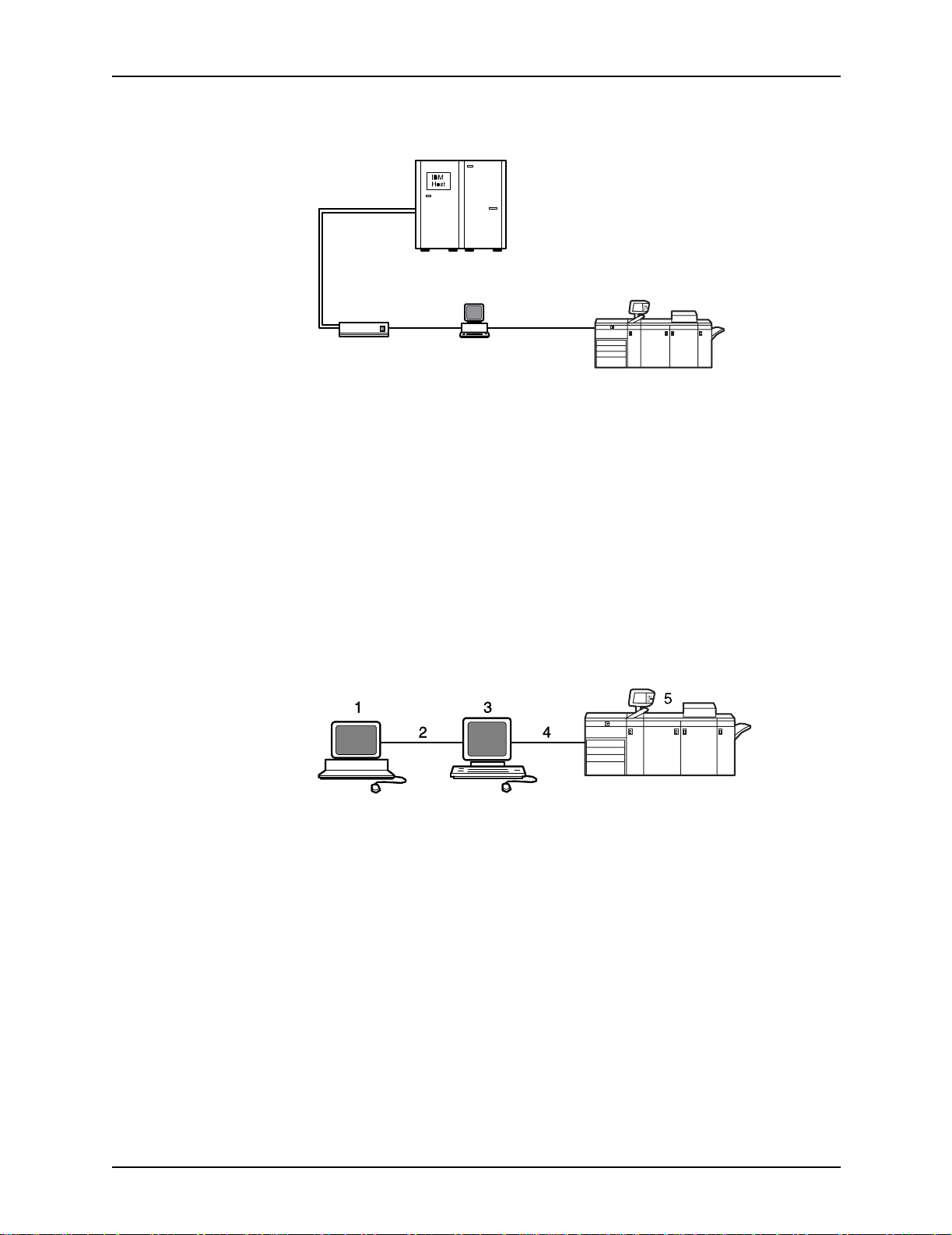
Figure 1-2. Printing system: TCP/IP configuration
1. Host system (PC or mainframe)
2. Interface network (Ethernet or Token Ring)
3. Printer controller
4. Printer interface cables
5. Printer
For in formation on the various printer configuration options, refer
to the “Printer components and options” chapter of this guide.
1-6 Installation Planning Guide
Page 27
System overview
Channel interface board and channel cable connector box—channelattached systems only
The channel interface board, connected to the channel cable
connector box, handles all IPDS communications and
handshaking with PSF on the host when the NPS/IPS is
receiving data over a channel. (It is not used when the NPS/IPS
is printing data using TCP/IP.)
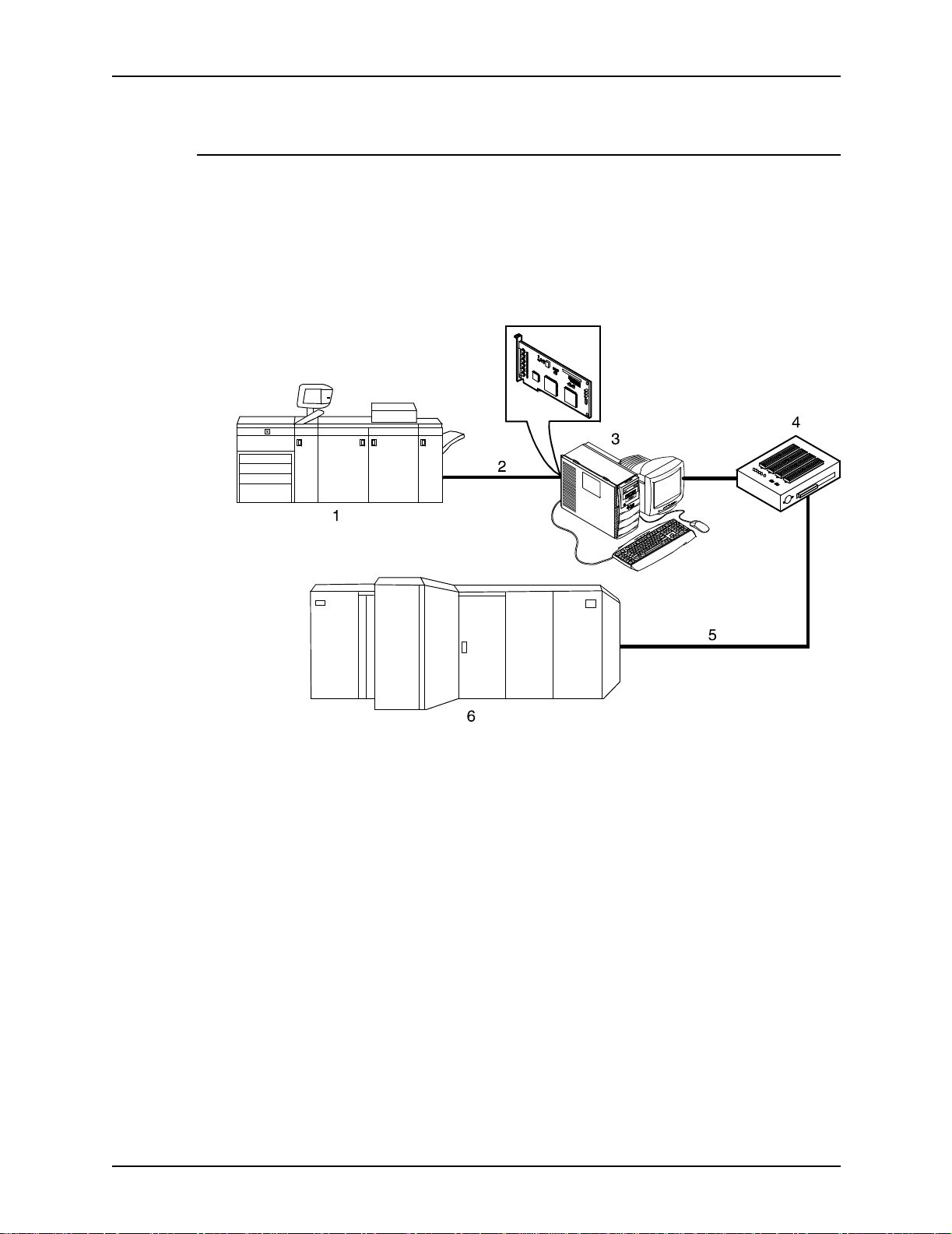
Figure 1-3. Channel interface board and channel cable
connector box
1. Printer
2. Printer control and video cable
3. Printer controller with channel interface board
4. Channel cable connector box
5. Channel cables
6. Host system
NOTE: The customer is r esponsible for obtaining, stringing, and
maintenance of the bus and tag cables. The bus and tag cables
must be fully populated cable sets.
Installation Planning Guide 1-7
Page 28

System overview
IPDS data stream
All IPDS resources (print data sets, page definitions, form
definitions, page segments, fonts, and overlays) that are
supported by the IBM 3825 and 3827 printers are supported by
the Xerox software. Additionally, the data towers that are
supported within the AFP en vironmen t by the IBM 3825 an d IBM
3827 printers are fully supported by the software. Data towers
supported are:
• IM Image IMD1
• FOCA: Font Object Content Architecture
• MO:DCA-P: Mixed Obj ect Document Cont ent Architecture f or
Presentation
• PTOCA PT1, PT2, and PT3: Presentation Text Object
Content Architecture
• IOCA: Image Object Content Architecture
• GOCA: Graphics Object Content Architecture
• BCOCA: Bar code Object Content Architecture
• OL1: Overlay One
• PS1: Page Segment One
• Line mode data streams
Each of the data objects f ollo w the same object rule of conta ining
delimiting fields with structure d fields describing each object.
1-8 Installation Planning Guide
Page 29

Network PDL printing envi ronment
Figure 1-4. DocuColor NPS/IPS system components
1. Customer-supplied client PC or workstation
2. Customer-supplied network
3. Xerox-supplied printer controller
4. Xerox-supplied printer interface
5. DocuColor printer
System overview
Customer-
supplied client PC
or workstation
Customer-
supplied network
Networks
Users create their documents at the networked client PCs or
workstations using software applications that generate PDL
output. When ready to print, users submit the documents to the
printer controller.
The customer needs to supply one or more of the following
networks:
• Ethernet local area netwo rk (LAN) running TCP/IP, AppleTalk,
or Nove ll NetWare network protocol.
• Token Ring running TCP/IP, Novell, or AppleTalk network
protocol.
Both network client workstations and the IBM host can
communicate with the controller over a network.
Ethernet LAN
Users of networke d client workstatio ns may send print jobs to the
DocuColor NPS/IPS prin ter o v er the Et hernet LAN using TC P/IP,
AppleTalk using EtherTalk Link Access Protocol (ELAP), or
Novell NetWare 3.1x as the network protocol.
Installation Planning Guide 1-9
Page 30

System overview
Regardless of printing or transmission protocol, the Ethernet
connection to the printer controller must be
compatible with the Institute of Electrical and Electronics
Engineers (IEEE) 802.3 standard.
Token Ring
Users of network client workstations may send pr int jobs to the
printer over Token Ring networ k using TCP/IP, Novell 3.x, or
AppleTalk network protocol.
Regardless of printing transmission protocol, the Token Ring
connection to the printer controller must be compatible with the
Institute of Electrical and Electronics Engineers (IEEE) 802.5
standard.
Multiple network devices
Multiple network devices ma y be insta lled on the same controller .
The default network device that ships with your controller is a
100 Mbit Ethernet connection. You may install other network
devices by installing additional network cards, provided each
card has a unique network to which it connects. For example, if
you use a Tok en Ring netwo rk connection, y ou hav e the option of
using the default Ethernet device as a secondary network.
If you choose to install multiple network devices on your
controller, the following parameters apply:
• You must sel ect a prim a ry network device and designate any
others as secondary. The primary network device does not
have to be the default Ethernet device that ships with your
controller; it can be any of the network devices installed.
• You must run the TCP/IP protocol on the primary network
device. You may also r un TCP/IP on other network devices.
For each network device running TCP/IP, you must specify a
unique IP address and IP netmask. For the primary network
device, you must specify the HostName and router IP
address. The HostName for any secondary devices is
created from the name chosen for the primary device.
NOTE: You may not use the controller as an IP router.
Consequently, the router IP address must be on the primary
network devices network only.
1-10 Installation Planning Guide
Page 31

• You may run the AppleTalk protocol on only one network
device. The network device on which AppleTalk is run does
not have to be the pr imary network device.
• You may run Novell protocols on only the primary network
device.
Network client components
To send print jobs to the NPS/IP S p rinter, the customer needs to
provide the proper client hardware as well as operating system
and network software.
Supported client hardware and operating systems
Xerox NPS/IPS supports the following types of networked client
workstations and operating systems:
• Sun Workstation running Solaris 8.0
System overview
• PC running MS-DOS 6.2 and Microsoft Windows 95, 98, NT,
4.0, 2000, and ME using Ethernet with TCP/IP or Novell
NetWare 3.11 and 3.12
NOTE: Customers using Novell 4.1 must set the “Bindery
Emulation Mode” to be backwards compatible with Novell
3.12.
• PC 386 or 486 , running M S-DOS , v er sion 6.2 , with one of the
following TCP/IP packages:
– PathWay Access 3.1, Wollongong Integrated Networking/
Transmission Control Protocol (WIN/TCP) for DOS,
release 6.0
– File Transfer Program (FTP) software, PC-TCP/IP, release
3.0 or higher
– Sun Personal Computer–Network File Services (PC-
NFS), version 5.1
• IBM RS/6000 running IBM AIX, version 4.1
• HP/Apollo running HP-UX, version 10.01
• DECStation 5000/200 running DEC Ultrix, version 4.3
• Apple Macintosh, S ystem 7. x or 8.x, using App leTalk through
EtherTalk, phase 1 or 2
• Any system that supports RFC-1179 lpr/lpd
Installation Planning Guide 1-11
Page 32

System overview
NPS/IPS software may be compatible with workstation models
and software versions other than those listed above.
Client networking software
TCP/IP networki ng software, Novell, or Apple Macintosh Printer
Access Protocol (PAP) networking software must be installed on
your client workstations. This software provides network
communication with the prin ter controller, which allows you to
submit print jobs and check job status.
To submit jobs, you need a d river, a job submission client like
XDS or the Xerox client software , or lpr capability.
NOTE: The printing options available to a client user vary
according to the networking software loaded on the client
workstation.
For additional information on submitting jobs from a client
workstation, refer to the
Client
.
Guide to Submitting Jobs from the
Responsibilities
It is your responsibility to supply, install, and maintain hardware
and software on a ny PC , UNIX workstation, or Macintosh system
used to generate documents for printing. You are also
responsible for obtaining, installing, and maintaining the required
Ethernet LAN or Token Ring network, transceivers, cables, and
connectors.
Xerox is responsible for the physical installation and service of
the printer and printer controller hardware and software
components. You have the general responsibility for the sit e of
ensuring that the right personnel, supplies, and that network
hardware and software is available. Refer to the “Preparing for
installation” chap ter of thi s gu id e for a detailed description of the
shared responsibilities of the customer and of Xerox.
1-12 Installation Planning Guide
Page 33

Sixth Sense
System overview
Sixth Sense is a unique suite of diagnostic tools that allows
Xerox customer service engineers, analysts, and consultants to
serve customers more effectively.
Sixth Sense is intended to automate and expedite the range of
service-related support functions. Sixth Sense is a tool that
enables Xerox to provide benchmark service support. Xerox
customers benefit from the ability to bring broader support to
focus more quickly.
For e xamp le, Si xth Sense can a llow t he service represe ntative to
repeatedly "preview" the condition of the system prior to an
actual site visit. This may provide the ability to determine the
correct part or piece of information to have on hand when the site
visit is made.
Sixth Sense is a no-charge feature available to customers
through Xerox service. The customer need only provide an
analog phone line for use by the Sixth Sense modem
connection. F or thos e customers una ble to d edicate a phon e line
to the Sixth Sense connection, three and five port phone share
devices are available for purchase.
To take advantage of Sixth Sense, the customer needs to:
• Request Sixth Sense enablement through Xerox Service
• Provide an analog phone line
• If necessary, purchase an optional phone share device.
More information abou t the Sixth Sen s e can be found in the
Troubleshooting Guide
for your system.
Installation Planning Guide 1-13
Page 34

System overview
1-14 Installation Planning Guide
Page 35

2. Controller components and options
The printer controller provides the printer with print data and
commands, and receiv es status inf ormation from th e printer . This
chapter describes the components and options available for the
controller.
Printer controller components
The printer controller consists of a specially-configured Sun
workstation and uses prop rietary Xerox h ardware, firmware, and
software.
Sun Blade 1000 works tat ion
The printer controller is based on the Sun Blade 1000, a
workstation with a high-performance architecture for complex
processing tasks. It contains the following hardware
components:
• Processor (system unit) containing the following:
– Two UltraSPAR C III 750 Mhz central processing unit
(CPU) modules
– 4 GB memory (four 1 GB Dual In-line Memory Modules, or
DIMMs)
– 36 GB hard disk drive
– DVD-ROM drive
– 3.5 inch diskette drive
• Keyboard and mouse
• Monitor
• Optional Token Ri ng board
• Two printer controller Inter face (PCI) boards installed in the
processor to interface with the print engine.
Installation Planning Guide 2-1
Page 36

Controller components and options
Optional
components
For channel connection to a host for IPDS printing, the system
may use a channel in ter face board that is connected to a
channel cable connector box.
An external 4 mm ta pe drive is available and recommended for
backing up site files. A typical color calibration file is 1.5 MB.
A second internal 36 GB hard disk drive is optional, as are two
additional external disks.
6
s
m
e
t
s
y
s
ro
c
i
m
1
2
5
4
3
Figure 2-1. Components of the printer controller
1. Monitor
2. Mouse
3. Keyboard
4. Diskette drive
5. DVD-ROM drive
6. Processor
2-2 Installation Planning Guide
Page 37

Controller components and options
Processor The central processing unit contains the memory, internal disk
drive, a graphics board, a DVD-ROM drive, a diskette drive,
power receptacle and outlet, connectors and ports.
• Memory: Four 1 GB Dual In-line Memory Modules, or DIMMs
are provided as a standard feature of the processor.
• Hard disk drive: A 36 GB primary disk drive is provided as a
standard feature of the processor. The operating system, the
NPS/IPS applicat ion, and an y queued print jobs are stored on
the internal disk. This disk cannot be used to store other
applications or data except as directed by your service
representative.
• Graphics board: The Creator-3D series 3 graphics board is
provided as a standard feature of the processor.
• Diskette drive: Diskettes inserted into a diskette drive are
used to install fonts and to load files to, and back up files
from, the internal disk drive. The diskette drive uses industry
standard 3.5 inch, 1.44 MB, double-sided, high-density
diskettes.
• DVD-ROM drive: The DVD-ROM drive is a high density,
read-only, optical laser storage device used for loading the
NPS/IPS operating system and other files. The CD-ROM
drive is located in the processor above the diskette drive.
• Back panel: The back panel of the processor has a power
receptacle an d outlet, conn ectors, connect or openings, and
ports. The following figure shows the back panel of the
controller.
Installation Planning Guide 2-3
Page 38

Controller components and options
1
2
3
4
5
6
7
8
9
10
11
12
13
14
15
Figure 2-2. Back panel of the printer controller
1. Access panel lock block
2. Serial connectors A and B, DB-25
3. Parallel connector
4. SCSI connector
5. Universal serial bus (USB) connectors
6. Twisted-pair Ethernet (TPE) connector
7. IEEE 1394 connectors
8. Fibre Channel-Arbitrated Loop (FC-AL) connector
9. Audio module headphones, line-in, line-out, and
microphone connectors
10.Graphics card / video connector (frame buffer 0)
11.PCI card slot 4
12.Graphics card / video connector (frame buffer not used)
13.PCI card slots 3 and 2
14.Power connector
15.PCI card slot 1
2-4 Installation Planning Guide
Page 39

Controller components and options
Keyboard The keyboard consists of alphanumeric keys similar to a
typewriter, symbols and special character keys, an extended
character set, and function keys. The keyboard is one of your
main methods of communicating with the printer. You can use
the keyboard to make selections, and to enter commands that
control functions such as requesting sample prints, or shutting
down the system.
Mouse The mouse is another ma in method of communicating with the
printer.
Display monitor The 18.1-i nch LC D mo nitor allo w s y o u to in ter act w ith th e printer
and to monitor its interaction with the various components.
During a print job, printer error messages may display to notify
you of any unexpected conditions.
NOTE: For information on channel-attached systems, refer to
the chapter, “IPDS printing environment”.
NOTE: Printer controller hardware configurations are subject to
upgrade.
Printer controller software and fonts
The installation of printer controller software is performed by your
service representative once all the hardware components are in
place and properly connected. The following is a summary of
major software components installed on the printer controller:
• Xerox printer controller software
– UNIX Sun operating system
NOTE: The Sun operating system used on the controller
is based on the standard Sun operating system; however ,
it has been customized for use with the Xerox printer
controller. Therefore, not all standard Sun operating
system features are availabl e.
– DocuPrint Print Service Software including software
components for the user interface, driver, decomposers,
Job Pool Manager, and other operating system utilities.
Installation Planning Guide 2-5
Page 40

Controller components and options
• Xerox Client Software
– Xerox client protocol software (print command) can be
downloaded to client workstations or PCs as a means to
communicate with the printer controller
• Adobe Type 1 PostScript fonts
– Courier (Courier, Bold, Oblique, Bold Oblique)
– Helvetica (Helvetica, Bold, Oblique, Bold Oblique, Light,
Light Oblique, Black, Black Oblique Condensed,
Condensed Oblique, Condensed Bold, Condensed Bold
Oblique Narrow, Narrow Bold, Narrow Oblique, Narrow
Bold Oblique)
– ITC Av antGard e Gothic (Book, Book Ob lique , Demi, Demi
Oblique)
– ITC Bookman (Demi, Demi Italic, Light, Light Italic)
– ITC Garamond (Light, Light Italic, Bold, Bol d Italic)
– ITC Korinna (Korinna, Kursiv Regular, Bold, Kursive Bold)
– ITC Zapf Chancery (Medium Italic)
– ITC Zapf Dingbats (Medium)
– New Century Schoolbook (Roman, Bold, Italic, Bold Italic)
– Palatino (Roman, Bold, Italic, Bold Italic)
– Symbol (Medium)
– Times (Roman, Bold, Italic, Bold Italic)
Using font installation commands, you can load oth er Type 1
PostScript fonts in *.PFB file format from a MS-DOSformatted, 3.5-inch diskette or CD-ROM or DVD-ROM. Refer
to the
more information on the font installation commands. Type 1
and Type 3 PostScript fonts can also be downloaded with a
print job.
• PCL fonts: Intellifont (scalable)
– CG Times (Medium, Italic, Bold, Bold Italic)
– Universe (Medium, Italic, Bold, Bold Italic)
Guide to Configuring and Managing the System
for
– Universe Condensed (Medium, Italic, Bold, Bold Italic)
– Courier (Medium, Italic, Bold, Bold Italic)
– Letter Gothic (Medium, Italic, Bold)
– Albertus [Medium (semi-bold), Extra Bold
2-6 Installation Planning Guide
Page 41

Controller components and options
– Antique Olive (Medium, Italic, Bold)
– Clarendon Condensed (Bold)
– Coronet (Medium Italic)
– Garamond [Antique (medium), Kursiv (Italic), Halbfett
(Bold), Kursiv Halbfett (Bold Italic)]
– Marigold (Medi um )
– CG Omega (Medium, Italic, Bold, Bold Italic
• PCL fonts: Truetype (scalable)
– Arial (Medium, Italic, Bold, Bold Italic)
– Times new Roman (Medium, Italic, Bold, Bold Italic)
– Symbol (Medium)
– Wingdings (Medium)
• PCL fonts: Bitmap
– Line Printer (16.67 pitch / 8.5 point medium)
• MICR fonts
E13B fonts in PCL and PostScript are also provided for 96/
4635/180 MICR system s .
NOTE: The resident fonts are used for PostScript and PCL
printing.
Installation Planning Guide 2-7
Page 42

Controller components and options
2-8 Installation Planning Guide
Page 43

Printer components
3. Printer components and options
The printer processes the electronic data and images received
from the control ler and p roduces th e printed out put. This ch apter
describes the components and options available for the printer.
The standard printer components are the printer control panel,
the touch screen, the offset catch tray, and the feeder trays.
Labels are located throughout the printer to assist you with a
variety of tasks such as clearing a paper jam.
Figure 3-1. DocuColor 2060 NPS/IPS
1. Touch screen
2. Printer control pane l
3. Dry ink / toner compartment
4. Offset catch tray
5. Right front door
6. Left front door
Installation Planning Guide 3-1
Page 44

Printer components and options
7. Transport module
8. Tray 3
9. Tray 2
10.Tray 1
11.Upper door
Input tray capacity Tray capacity for the input trays is:
• Trays 1 and 2 hold 550 sheets of 24-pound or 90 gsm bond
paper.
• Tray 3 holds 2200 sheets of 24-pound or 90 gsm bond paper.
NOTE: For special stock, use tray 3.
All three input trays have buttons to specify weight. In addition,
tray 3 has selections for paper size (Non Standard or Standard),
and the paper type (Coated or Uncoated). You must use these
specifications for the printer to print properly. For the procedure
on loading paper and specifying the weight, paper size and
paper type, refer to the
Maintenance
, “Paper trays” chapter.
Guide to Performing Routing
Output tray
capacity
NOTE: Although the tray input buttons for the DocuColor 2060
require you to specify weight, you also specify media weight
when using the Set Tray command at the printer co ntroller. The
buttons on the tray require you to specify weight in gsm, whereas
the Set Tray command allows you to use any unit of
measurement for weight. Therefore, the number you specify on
the tray, and the number you specify using Set Tray may be
different numbers, while still referring to the same actual weight.
Additionally, Set Tray allows you to specify 0 to indicate no
preference.
The offset catch tray holds 500 sheets of 24-pound or 90 gsm
bond paper.
If you have the optional high-capacity stacker (HCS) or highcapacity stacker stapler (HCSS), the built-in top tray in these
devices replaces the standard offset catch tray. Refer to the
“Printer options” section for information on these optional
stackers.
3-2 Installation Planning Guide
Page 45

Touch screen
Printer components and options
The touch screen displays messages that indicate the status of
the printer during idle, run, or fault conditions.
The touch screen displays the default screen selected in the
Tools Mode by your system administrator . The de fault screen can
be either the Basic Features, Job Status, or Machine Status
screen. For information on the Tools Mode, refer to the
Performing Routing Maintenance
, “Default settings” chapter.
Guide to
NOTE: For most functions, you will use the printer controller
rather than the Touch Screen.
Message area
The message area at the top of the touch screen displays
messages concerning the printer status, programming conflicts,
or errors. The messages may also provide instructions for the
operator.
Alert screens
Tabs, buttons, and icons
Some screen s on the touch sc reen display tabs that contain
various selectable options.
Features and options are initially set to the factory default
settings. These settings can be changed by your system
administrator in Tools mode.
An alert screen has a red bar across the screen when a
consumable product such as dry ink needs to be replaced. An
alert screen also indic ates that the printer is unable to print
because of a fault condition. Follow the instructions on the
screen to resolve the pr oblem and resume printing.
Installation Planning Guide 3-3
Page 46

Printer components and options
Figure 3-2. Alert screen
Printer control panel
Your DocuColor 20 60 NPS/IPS has a contr ol panel with wor ds or
with international symbols.
Figure 3-3. Printer control panel with words
3-4 Installation Planning Guide
Page 47

Printer components and options
Figure 3-4. Printer control panel with international symbols
The function of each button is described in the following table.
NOTE: All functions may not be activated for your system.
Table 3-1. Control panel buttons
Name and symbol Function
Features Not used for DocuColor 2060 NPS/IPS.
Power Saver Puts the system in a standby status mode, where the fuser temperature is lowered.
The factory default is 60 minutes. The power saver time out can be changed in
Tools to reflect a value from 1 to 240 minutes.
Job Status Displays a list and the current status of all jobs submitted on the touch screen.
CAUTION
The option to hold, release, promote, delete and see the options selected for each
job in the queue should not be used for DocuColor 2060 NPS/IPS. These
functions must be performed at the printer controller.
Installation Planning Guide 3-5
Page 48

Printer components and options
Table 3-1. Control panel buttons (Continued)
Name and symbol Function
Language Allows you to select one of two languages to be displayed on the touch screen.
Access Allows access to the password-protected Tools Pathway and the Auditron
Administration Pathway. For information on the Tools mode, refer to the
Performing Routing Maintenance
Machine Status Gives the status of the paper trays, machine details, error log and maintenance
information. Machine Status is where you will find the serial number for the printing
system, the customer support telephone numbers and the meters that show the
count for color, black and white, color large size and total output.
, “Default settings” chapter.
Guide to
Review Not used for DocuColor 2060 NPS/IPS.
Help Additional information useful in completing a task is displayed on the touch screen.
Clear All Not used for DocuColor 2060 NPS/IPS.
Interrupt Not used for DocuCol or 2060 NPS /IP S.
3-6 Installation Planning Guide
Page 49

Printer components and options
Table 3-1. Control panel buttons (Continued)
Name and symbol Function
Pause Not used for DocuColor 2060 NPS/IPS.
Start Press the Start button in the Tools mode for certain settings. For information on the
Tools mode, refer to the
settings” chapter.
Keypad Use the keypad to enter:
• Your password for access to Tools mode, or
• The number of copies desired for a job.
C Not used for DocuColor 2060 NPS/IPS.
Guide to Performing Routing Mainte nan ce
, “Default
Audio tones
The printer sounds an audibl e ton e to dire ct your attention to a
printer prob le m .
There are three tones:
• Attention
The Attention tone indicates that the button pressed is not
able to be selected.
• Button selection
The Button Selection to ne indicates that t he button pressed is
able to be selected.
•Fault
The Fault tone indicates that the printer is in a fault condition
and will not operate until the fault is cleared.
The tones can be activated or deactivated through the Tools
mode. Fo r the procedure, refer to the
Routine Maintenance
, the “Default settings“ chapter.
Guide to Performing
Installation Planning Guide 3-7
Page 50

Printer components and options
Identifying the internal components
Figure 3-5. Internal vi ew of the DocuColor 2060
1. Dry ink / toner cartridges
2. Exit module paper path
3. Paper path
4. Serial number label
5. Transport paper path
6. Upper door
7. Tray 1
8. Tray 2
9. Tray 3
Dry Ink cartridges
The colors, from left to right, are black, cyan, magenta and
yello w . Refe r to the
instructions on changing the cartridge.
Guide to P erf orming Routi ne Maintenan ce
for
3-8 Installation Planning Guide
Page 51

Printer components and options
Serial number label
If the DocuColor 2060 has a loss of power making it imp os sible
to access the Machine Details tab to get the serial number, open
the two main fr ont do ors . The serial n umb er lab el is in the cen ter
of the bottom frame of the printer.
Upper door
The upper door paper path transports paper from trays 1, 2 and
optional tray 4 to the transport module.
Figure 3-6. Upper door
Installation Planning Guide 3-9
Page 52

Printer components and options
Figure 3-7. Paper Path
1. Fro m tr ay 4
2. Transport module
3. To the printer
4. F rom ho riz o nta l (d up lex) transport
5. Tray 1
6. Tray 2
7. Tray 3
Transport module
Figure 3-8. Transport Module Paper Path
1. Paper from trays 1, 2, and 4
3-10 Installation Planning Guide
Page 53

Printer components and options
2. Upper transport
3. To the printer
4. Single sided prints from the horizontal trans port
5. Lower transport
6. Paper from tray 3
7. Takeaway transport
Figure 3-9. Transport Module
The upper paper path in the Transport Module carries the paper
from the Paper Trays to the upper paper path of the printer.
The lower paper path in the Transpor t Module carries the paper
from the lower paper path in the printer to the upper paper path
in the printer when duplexing.
Installation Planning Guide 3-11
Page 54

Printer components and options
Paper path in the printer
Figure 3-10. Printer paper path
1. F ro m transport module
2. Alignment transport
3. Inverter gate
4. Vacuum transport
5. Fuser transport
6. To exit module
7. Inverter transport
8. From duplex Inverter transport
9. Horizontal tra nsp ort 1
10.Horizontal transport 2
11.To transport module
The paper path in the printer transfers an image to the paper and
fuses it for both the simplex and duplex selections. It has two
areas, the uppe r paper path an d the lower paper path. The uppe r
paper path is used f o r bo th sim plexing and duplexing. The lo wer
paper path is used for duplexing only. Horizontal transport 1
decurls the paper when printing duplex.
3-12 Installation Planning Guide
Page 55

Printer components and options
Exit module
Figure 3-11. Exit module paper path
1. Decurler
2. Duplex inverter transport
3. To printer
4. To inverter transport
5. F rom printer
6. To the output device
Figure 3-12. Exit Module
A completed print passes through the exit module to the offset
catch tray.
Installation Planning Guide 3-13
Page 56

Printer components and options
The exit module contains a decurler that removes the curl from
the paper which occurs during the fusing process.
The exit module also contains an inverter, which turns the paper
over so that side 2 can print when duplexing or when face down
output is selected.
Printer options
DocuColor 2060 NPS/IPS prin ters are availabl e wi t h the
following options:
• High-capacity feeder (HCF)
• High-capacity stacker (HCS)
• High-capacity stacker stapler (HCSS).
These options allow you to customize your printing system for
increased effici ency and for specialized applications.
High-capacity feeder
Three feeder trays are provided as part of the printer base
configuration (feeder trays 1, 2, and 3). For the DocuColor 2060
NPS/IPS, the high-capacity feeder option increases the
versatil ity a nd produ ctivi ty of the printer w ith a n addit iona l feeder
tray (tray 4), increasing the feeder capacity by approximately
2,500 sheets.
Figure 3-13. Xerox DocuColor 2060 NPS/IPS high-capacity
feeder
3-14 Installation Planning Guide
Page 57

Printer components and options
1. Control panel
2. Left door
3. Right door
Tray capacity The high-capacity feeder tray holds 2500 sheets of 24-pound or
90 gsm bond paper.
NOTE: Do NOT fill above the MAX line.
Pap er stock
specifications
Tray 4 is designed to feed the commonly used paper sizes and
weights.
There are two positi ons in which pape r is fed into the printer . On e
of the positions is call ed l ong ed ge feed (LEF). Long edge refers
to the long edge of your paper. Whe n you see LEF, position yo ur
paper so that the long edge is fed first. The other position is
called short edge feed (SEF). Short edge refers to the short
edge of your paper. When you see SEF, position your paper so
that the short edge is fed first.
Installation Planning Guide 3-15
Page 58

Printer components and options
Special paper stock for tray 4 includes:
• Labels can be run, but are not recommended for tray 4
• Letterhead
• Drilled (hole punched) is not recommended to be run from
tray 4, but can be fed SEF
• Colored paper
• Coated and non-coated paper
• Tabbed inserts c an be run, but are not recommended for
tray 4.
High-capacity stacker
The high-capacity stacker is an optional finishing device that
provides stacking and offsetting capabilities for output into a
stacker cart.
NOTE: The Xerox DocuColor 2060 NPS/IPS can have a highcapacity stacker (HCS) or a high-capacity stacker stapler
(HCSS), but not both.
Figure 3-14. High-capaci ty stacker
1. Control panel
2. Back
3. Top cover
4. Right side
5. Front door access to stacker cart
3-16 Installation Planning Guide
Page 59

Printer components and options
6. Front
7. Decking plate to DocuColor 2060 NPS/IPS
8. Left side
Tray capacity The stacker cart has a capacity of 3500 sheets of 24 pound (90
gsm paper.
High-capacity stacker modes
The high-capacity stacker offers the following options for output.
Top Tray mode The high-capac ity stac k er di ve rts sheets that are to o smal l or too
large to be stac ked and proo f sets to th e top tra y. The ca pacity of
the top tray is 250 sheets of 24 pound (90 gsm) paper.
NOTE: When printing labels the back sometimes comes off
when using the Stack mode. Use the Top Tray mode when
printing labels to avoid this problem.
Stack mode Stacks collated sets as received from the printer. The stacker
tray has a capacity of 3500 sheets of 24 pound (90 gsm) paper.
NOTE: When printing labels the back sometimes comes off
when using the Stack mode. Use the Top Tray mode when
printing labels to avoid this problem.
Installation Planning Guide 3-17
Page 60

Printer components and options
High-capacity stacker stapler
The high-capacity stacker stapler is an optional finishing device
that provides stacking, stapling, and offsetting capabilities for
output into a stacker cart.
NOTE: The Xerox DocuColor 2060 NPS/IPS can have a highcapacity stacker (HCS) or a high-capacity stacker stapler
(HCSS), but not both.
Figure 3-15. High-capaci ty stacker stapler (HCSS)
1. Control panel
2. Top tray
3. Offset catch tray
Tray capacity The HCSS offset catch tray has a capacity of 2000 sheets of 24
pound (90 gsm) paper. It has an offset mode that provides
separation between the stacked sets. The HCSS can also send
output to the Top Tra y.
3-18 Installation Planning Guide
Page 61

Printer components and options
High-capacity stacker stapler modes
The high-capacity stacker stapler offers the following options for
output.
Top Tray mode Sends each print to the top tray of the HCSS. The top tray also
accepts sheets that are div erted to it during a prob lem, and w hen
the system is in the job recovery mode. The top tray holds a
maximum of 250 sheet s of 24 lb. (90 gsm) paper.
Stack mode Stacks collated sets as received from the printer in the offset
catch tra y. The of fset catch tray has a capacit y of 20 00 sh eet s of
24 pound (90 gsm) paper.
Staple mode Staples each set and delivers it to the offset stacker stapler tray.
Installation Planning Guide 3-19
Page 62

Printer components and options
3-20 Installation Planning Guide
Page 63

4. Preparing for installation
This chapter assists you in preparing for the installation of your
Xerox DocuColor 2060 NPS/IPS.
Preparing for installation is a respo nsibility shared by personnel
at your site and Xero x. Your service representatives are av ail able
to discuss installation issues and to assist you in completing the
site installation tasks.
Before installation, you must select and prepare an appropriate
location for the printing system and order supplies. This chapter
helps you accomplish these tasks by provid ing the following
information:
• A summary of your responsibilities and those of your Xerox
service representative
• Connectivity requirements for setting up the NPS/IPS to
receive data from the IBM host
• A checklist of installation planning activities.
For information on contro ller power and space requirements,
refer to the “Controller specific ations and requir ements” chapter
of this guide. For facts about printer power and space
requirements, refer to the “ Printer specifications and
requirements” chapter of this guide.
Installation Planning Guide 4-1
Page 64

Preparing for in stallation
Responsibilities
Xerox responsibilities
This section describes your site responsibilities and the
responsibilities of your service representatives. Included are
some joint responsibilities.
This section lists the responsibilities of the service
representatives and system analysts before, during, and after
installation:
• Site selection
– Assist in site selection
– Inspect and approve the site.
• Installation
– Schedule the delivery of the hardware
– Monitor installation activities
– Assist you in ordering any supplies required
– Configure system parameters
– Assist with the configuration of input and output profiles
for use with third-party finishing devices
– Install the DocuColor 2060 NPS/IPS system
– Install optional Sixth Sen se har dware and software.
• Training
– Provide initi a l ope rator training
– Provide information and assistance in registering for
Xerox Customer Education classes or obtaining tutorials.
• Service
– Review preventive maintenance schedules and service
call procedures
– Provide ongoing maintenance
– Assist in resolving hardware and software problems.
4-2 Installation Planning Guide
Page 65

Customer responsibilities
Your responsibilities prior to, during, and after installation of the
DocuColor 2060 NPS/IPS system are to schedule and monitor
your installation activities. Refer to the “DocuColor 2060 NPS/
IPS installation planning checklist” and the “Network
preinstallation checklist” in this chapter for a complete list of
responsibilities.
Refer to t he “Xero x support services” appendix f or inf ormation on
services designed to support you prior to, during, and after your
installation.
• Site personnel
– Identify the person (or persons) at your sit e who will be
the primary interface with Xerox.
– After the installation of your DocuColor 2060 NPS/IPS,
there are a few ongoing tasks that must be performed.
These tasks may include all or some of the following:
Preparing for installatio n
• Meter reading and reporting
• Overseeing routine maintenance
• Placing service calls for hardware problems
• Ordering additional documentation, software, or fonts
• Arranging additi o nal operator trai ning
• Maintaining an adequate inventory of consumable
supplies.
It is your responsib ility to design ate a perso n (or person s)
to perform these tasks.
• Operator and Administrator training
– Select personnel for Operator and Administration training.
– Set up a training schedule.
• Site prepara t ion
– Select and prepare the site for DocuColor 2060 NPS/IPS
system installation including proper power, air
conditioning, and work space.
– Plan and schedule installa tion activities.
– For channe l-attached syste ms: Provide you r host channel
address to your Xerox representative.
Installation Planning Guide 4-3
Page 66

Preparing for in stallation
– Install the necessary network connections required to
connect client workstations to the printer controller. Refer
to the “Network preinstallation checklist” in this chapter.
– Install Ethernet or Token Ring to system location.
– Obtain the necessary interfaces, cables, transceivers, etc.
NOTE: You are responsible for obtaining, stringing, and
maintaining fully-populated bus and tag cables for
channel-attached systems.
– Sysgen your host to print to an AFP Type1, Group 3
printer. Refer to your IBM documentation for further
information.
– Provide a list of th e stocks you want in your default input
tray configuration.
– Review the
thoroughly.
– Hav e the required par ameters defi ned fo r configuring PSF
to print on the NPS/IPS. Refer to the “Defining the
channel attached printer to the host” or the “Defining the
printer to the host: TCP/IP attachment” appendix of this
guide for examples and explanations of these parameters.
• Client workstations: Make sure all client workstations that
will be submitting print jobs have the proper hardware,
operating system, and networking software supported by the
DocuColor 2060DocuColor NPS/IPS system as client
platforms.
• Training
– Select the personnel to undergo operator training.
– Set up the operator training schedules.
• Applications
– Work with your Xerox system analyst to determine
requirements for the initial applications.
NPS/IPS Installation Planning Guide
– In a mixed environment, where there is a variety of
printing systems, discuss print quality differences with
your service representative.
4-4 Installation Planning Guide
Page 67

Make sure that your system specialists are familiar with the
software specific to y our orinter; system software is not th e same
for all laser printing systems. If your system specialists are
familiar with one of these operating systems and you are
converting to or adding another, they should be aware of the
differences.
Installation planning checklist
To aid you in installation planning of the DocuColor 2060 NPS/
IPS, this section provides a checklist, listing tasks you and your
service representative need to complete in the weeks before
installation. If you have questions about any of these activities,
contact your sales or service representative.
Use the timeframes in this checklist as guidelines. It is best to
consult your suppliers to determine the exact lead times they
require.
Preparing for installatio n
Table 4-1. DocuColor 2060 NPS/IPS installation planning checklist
Week Activity Reference Responsibility
-4 • Select location for DocuColor
2060 NPS/IPS system.
• Identify networked client
workstations to be used. Make
sure the hardware, operating
systems, and networking software
are supported by the DocuColor
2060 NPS/IPS.
• In the United States, sign up with
Xerox Documentation and
Software Services. Order
additional documentation, if
needed.
• In the United States, register for
Xerox Customer Education
classes, if needed.
Chapters 5 and 6
Chapter 4 and
Appendix D
Appendix B
Appendix B
Customer
Customer
Customer
Customer and
Xerox
Date
completed
_________
_________
_________
_________
Installation Planning Guide 4-5
Page 68

Preparing for in stallation
Table 4-1. DocuColor 2060 NPS/IPS installation planning checklist (Continued)
Date
Week Activity Reference Responsibility
completed
-3 • Schedule hardware delivery.
• Prepare the site:
– Provide a table with adequate
space for hardware and
cables.
– Ensure and install proper
electrical receptacles.
– Obtain and string bus and tag
cables (must be fully
populated), if needed.
– Install network to system
location.
– Install Token Ring to system
location (if appropriate).
– Install Ethernet to system
location (if appropriate).
– Establish network addresses
and logical unit names for print
server and user workstations.
– Complete preinstallation
checklist.
– Provide table with adequate
space for hardware and
cables.
– Ensure and install proper
electrical receptacles.
– Ensure proper operating
environment.
– Generate the host for an AFP1
device and IPL, as required.
– Provide analog phone line
access for optional Sixth
Sense installation.
Sales rep
Chapters 4 to 6
Customer and
Xerox
Customer
_________
_________
_________
_________
_________
_________
_________
_________
_________
_________
_________
_________
_________
_________
-2 • Inspect and approve site.
• Order consumable supplies.
• Minimum supplies needed for
installation:
– Paper (2 cartons)
– Developer (1 carton)
– Fuser agent (2 cartons)
– Dry ink for DocuColor 2060
NPS/IPS (1 carton black)
After installation, you will need to
establish a procedure for ordering
supplies according to your ongoing
production requirements.
Chapter 4,
Appendix A and
sales rep
Xerox
Customer and
Xerox
_________
_________
4-6 Installation Planning Guide
Page 69

Preparing for installatio n
Table 4-1. DocuColor 2060 NPS/IPS installation planning checklist (Continued)
Date
Week Activity Reference Responsibility
completed
-1 • Schedule operator training.
• Define parameters needed to
configure PSF for connectivity to
the NPS/IPS printer.
Install • Ensure supplies are available.
• Ensure system administrators are
available during software
installation.
• Provide preinstallation checklist
and network address of print
server (or host file containing this
information) to Xerox personnel.
Also, designate two client
workstations if applicable, for
Xerox client software installation.
• Provide host channel address and
channel unit address (if printing
via channel).
• Provide host IP address.
• Sysgen your host to print to an
AFP Type 1, Group 3 printer.
• Set up Data Transfer Mode.
• Install DocuColor 2060 NPS/IPS
system hardware and software.
• Load Xerox client software on
client workstations.
• Have operators available for
training.
• Check documentation and
software kits for completeness.
• Have test jobs ready to run.
• Provide stocks needed for default
input configuration.
• Provide parameters needed to
configure PSF for connectivity to
the NPS/IPS printer.
Systems analyst Customer and
Xerox
Chapter 4 and
Appendix A
Chapter 4
Customer
Customer
Customer
Xerox
Customer
Customer
Customer
Customer
Customer
Customer
_________
_________
_________
_________
_________
_________
_________
_________
_________
_________
_________
_________
_________
_________
_________
Postinstall
• Become famili ar with support
services available.
• Establish supplies ordering
procedure.
• Provide ongoing printer controller
and DocuColor 2060 NPS/IPS
printer maintenance.
• Adjust the printer alignment and
magnification.
• Order additional documentation,
as necessary.
Appendix B
Appendix A
Guide to
Performing
Routine
Maintenance
Appendix B
Customer
Customer
Customer and
Xerox
Xerox
Customer
_________
_________
_________
_________
_________
Installation Planning Guide 4-7
Page 70

Preparing for in stallation
NPS/IPS network installation checklist
The DocuColor 2060 NPS/IPS system is installed and configu red
by you r service representativ e. The se rvice representativ e needs
certain information about your network environment to complete
the DocuColor 2060 NP S/IP S printer controller software
installation. Use the “Network preinstallation ch ecklist” table in
this chapter to gather the necessary information for the
installation.
Some of the items in the checklist may not apply to your
environment. Fill in those items that you know may apply, and
refer to your network administrator for information, if neces sary.
NOTE: If you are installing the DocuColor 2060 NPS/IPS in a
Novell NetWare environment, refer to this chapter and your
Novell network NPS/IPS administrator to assist you in
completing the checklist in the “Network preinstallation checklist”
table.
The information you may need to provide is defined as follows:
Hostname A unique name that designates a node on the network. You may
use up to 32 characters: upper and lower case alpha (a-z and AZ), integers (0-9), and hyphens (-). The n ame you choose may
be the same as the printer name.
IP address Series of four integ ers between 0 and 255 separated b y a period,
such as 192.9.200.1, to create an IP address for the DocuColor
2060 NPS/IPS system. (Do not use all z eros or designat e 255 f or
all integers when assigning an IP address.)
• You must assign a unique, valid IP address for each TCP/IP
network to which the NPS/IPS is attached.
NOTE: To avoid routing problems that will slow down the
controller, the IP addresses you assign must belong on
different TCP/IP subnets, as determined by the IP subnet
netmask.
• If you are not on a TCP/IP network, use th e Xerox- supplied IP
address value (192.9.200.1), or the IP address value
assigned by your network administrator.
4-8 Installation Planning Guide
Page 71

Preparing for installatio n
IP netmask Series of four integers betw een 0 and 255 separ ated by a period,
such as 255.255.255.0 to create an IP netmask. (Do not use all
zeros or designate 255 for all integers when assigning an IP
netmask, and do not use the IP address value.)
• If you are on a TCP/IP network, assign a valid IP netmask.
• If you are not on a TCP/IP network and you used the Xeroxsupplied IP address value (192.9.200.1), use 255.255.255.0
for the IP netmask.
IP broadcast
address
Default router Series of four integers between 0 and 255 sep arated b y a period,
Series of four in tegers betwe en 0 and 255 separate d by a period,
such as 255.255.255.0, to create an IP broadcast address. (Do
not use the IP address value.)
• If you are on a TCP/IP network, assign a valid IP broadcast
address.
• If you are not on a TCP/IP network, use th e Xerox- supplied IP
broadcast address value (255.255.252.0), which is a pl us (+ )
sign.
such as 188.9.234.1, to specify a default router. Most TCP/IP
networks broa dcast routing information.
CAUTION
Specify a default router only if your network does not specify
broadcast routin g information.
• If the TCP/IP n etwork does not broadcast routing inf ormation,
specify an IP address of an e xisting route r that is on the same
subnet as the DocuColor 2060 NPS/IPS.
• If you are not on a TCP/IP network, specify the default of
NONE.
Superuser
password
(UNIX root
password)
Installation Planning Guide 4-9
Select a password to prevent unauthorized access to your
superuser account. You can select a series of any ASCII
characters, except those that your UNIX system interprets in a
special way. Passwords have no limits on the number of
characters, but the system uses only the first eight characters to
administer passw ord security. The passwo rd selection you make
is case sensitive to the system.
Page 72

Preparing for in stallation
CAUTION
Select a password that cannot be easily obtained by others to
avoid unauthorized access to your account. This is not the same
password used for Operator or Adm inistrator funct ions.
AppleTalk network
information
Accounting
information
Xerox client
software
If the DocuColor 2060 NPS/IPS is installed in an Ap pleTalk
network enviro nment, indicate whether your AppleTalk network is
phase
1 or 2. Also, indicate the AppleTalk zone name you want the
DocuColor 2060 NPS/IPS to locate. The zone name must be the
same name as the existing zone used on the network to which
the DocuColor 2060 NPS/IPS is attached. In addition, you must
specify the network device on which AppleTalk runs.
NOTE: Do not use the ampersand (“&”) in the zone name to
avo id conflict with UNIX e xpre ssions. If the ampe rsand char acter
must be used, enter “\\&” instead.
Indicate whether to set an int erval on the system to au tomatically
purge accounting information. If accounting information is not
purged manually or automatically, the system disk can reach
storage limits. To keep your system running at optimum speed,
you need to periodically purge accounting data.
Indicate whether you have Xerox client software installed, and
are supporting Xerox clients on the network.
lpr and lpd Indicate whether to enable client use of lpr and lpd job
submission and status commands.
UNIX command
tool
Retry count Determine whether the DocuColor 2060 NPS/IPS system
4-10 Installation Planning Guide
Indicate whether to ha ve a UNIX command tool ava ilable for use
in the background menu.
supports a print production environment, or whether the system
remains unattended. Once you determine the environment the
DocuColor 2060 NPS/IPS supports, you must decide the number
of attempts the system makes to print a job before a sequencer
restart causes the job to be held for intervention.
• If the DocuColor 2060 NPS/IPS supports a print production
environment, you may want to specify a large number or zero
as the number of attempts the system makes to retry a print
job. (Zero indicates an infinite number of retries.)
Page 73

• If the DocuColor 2060 NPS/IP S is unatte nded, you may want
to specify only 1 or 2 retries to print a job.
Novell network information
The Novell network information you provide to your service
representative is based on whether you configure the DocuColor
2060 NPS/IPS as a print server or a remote printer. Refer to this
chapter and your Nove ll network administrator for assistance, if
necessary .
NPS/IPS as a print server (PSERVER)
Provide the following information to the service rep resentative if
you configure DocuColor 2060 NPS/IPS as a print server on the
Novell network (for further information, refer to the “Installation
process” section in the “Installation” chapter of this guide):
Preparing for installatio n
• Nove ll fi le serv er na me—i ndica tes the na me of the fi le server
that the DocuColor 2060 NPS/IPS services. The file server
must have the appropriate print server definition and the
queue to be serviced.
• Print server name—indicates the name used by the
DocuColor 2060 NPS/IPS print server. A print server
definition with this name must exist on the file server that the
DocuColor 2060 NPS/IPS services. A single printer (type
Remote Other/Unkno wn) m ust be defi ned f or th is print server
and the queue (refer to the queue name below).
• Password for the print server—refers to a password you may
hav e a dded in t he prin t serv er defin iti on ( using P CO NSOLE ).
It is not necessary to add a password to a print server, and
there is no defau lt password.
• Queue name to service—refers to the name of the queue
from which the DocuColor 2060 NPS/IPS print server
accepts jobs. The queue must be defined on the file server
that the DocuColor 2060 NPS/IPS services. The single
printer that must be defined for the print server (as stated
above) must also be defined to ser vice the specified queue.
• Form names—distinct form names for DocuColor 2060 NPS/
IPS that map to the DocuColor 2060 NPS/IPS virtual printer
names.
Installation Planning Guide 4-11
Page 74

Preparing for in stallation
NPS/IPS as a remote printer (RPRINTER)
Provide the following information to the service rep resentative if
you configure DocuColor 2060 NPS/IPS as a remote printer on
the Novell network (for further information, refer to the
“Installation process” section in the “Installatio n” chapter of this
guide):
• Novell print server name—indicates the name of the print
server to which the DocuColor 2060 NPS/IPS will connect.
An advertising print server with this name must be running on
the Novell internet.
• Printer name(s) to service—refers to the name(s) of the
printers defined for the Novell print server. Virtual printers
should be defined with these names after DocuColor 2060
NPS/IPS installation is complete. These printers should be
defined as type Remote Other/Unknown.
IPX internal
network number
LAN network
number
Network framing
type
Specify the network number for the internal IPX network in the
DocuColor 2060 NPS/IPS server. This number must be globally
unique within the NetWare internet to which the DocuColor 2060
NPS/IPS is connected. (Do not assign a number that is used by
other machines to which the DocuColor 2060 NPS/IPS will be
connected.)
Specify the network number for the cabli ng system to which the
DocuColor 2060 NPS/IPS is connected, for example the
Ethernet or Token Ring segment.
Specify the network framing type used for IPX/SPX
communication by DocuColor 2060 NPS/IPS. There are eight
options:
• ETHERNET__II
• ETHERNET__802.3
• ETHERNET__802.2
• ETHERNET__SNAP
• TOKENRING
• TOKENRING__SNAP
• FDDI
• FDDI__SNAP.
4-12 Installation Planning Guide
Page 75

Preparing for installatio n
Choose a framing type used by the f ile server that communi cates
with DocuColor 2060 NPS/IPS. If you are using print server or
remote printer, and have the DocuColor 2060 NPS/IPS
communicate with a different machine for each, then choose a
framing type that is used by both of the machines.
If you are installing a new Novell network using Ethernet, it is
recommended that yo u choose the ETHERNET__II fr aming type
for the file server and the DocuColor 2060 NPS/IPS. If you are
using Token Ring and the Novell server has both TOKENRING
and TOKEN RING_SNAP enabled, use TOKENRING on the
DocuColor 2060 NPS/IPS. For FDDI networks running Novell, it
is recommended that you choose the FDDI framing type.
Ta ble 4-2. Network preinstallation checklist
Network Information Information you supply
Hostname
IP address for primary net device
IP netmask for primary net device
IP address for secondary net device #1 (if applicable)
IP netmask for secondary net device #1 (if applicable)
IP address for secondary net device #2 (if applicable)
IP netmask for secondary net device #2 (if applicable)
IP address for secondary net device #3 (if applicable)
IP netmask for secondary net device #3 (if applicable)
Primar y network device
Default router
Secondary network devices (if applicable)
Superuser passwo rd
Accounting information
Xerox client software
lpr and lpd
UNIX command tool
Retry count
Installation Planning Guide 4-13
Page 76

Preparing for in stallation
Table 4-3. Novell preinstallation checklist
Novell Network Information Information you supply
Novell network information (DocuColor 2060 NPS/IPS
as a print server)
Novell file server name
Print server name
Password for the print server
Queue name to service
Form names
Novell network information (DocuColor 2060 NPS/IPS
as a remote printer)
Novell print server name
Printer name(s) to service
IPX internal network number
LAN network number
Ethernet framing type (ETHERNET__II, 802.3, 802.2,
or SNAP; TOKENRING or TOKENRING_SNAP)
Table 4-4. AppleTalk preinstallation checklist
AppleTalk Network Information Information you supply
AppleTalk Phase 1 or 2
AppleTalk zone name
Network device used for the AppleTalk protocol
Connectivity requirements
A Token Ring network or an Ethernet local area network (LAN)
running Transmission Co ntrol Protocol/Internet Protocol (TCP/
IP), AppleTalk, or Novell NetWare software is a network
communications system, which can be used as an alternative to
the channel-attached configuration in which data is transmitted
via bus and tag cables and the PCI board. This network
communication system is used to transport documents from the
client workstation to the printer.
4-14 Installation Planning Guide
Page 77

Ethernet specifications
The Ethernet connection to the printer controller processor must
be compatible with the I nstitute of Elect rical and Electronics
Engineers (IEEE) 802.3 standard.
The Ethernet interface on the printer controller processor is a
10Mb/sec twisted pair standard (10BaseT and 100BaseT).
Attachment Unit Interface (AUI) Coax Ethernet is enabled with
an adapter ca ble.
Work with your system administrator to assess what type of
network you ha ve and what modifications need to be made to
supply an Ethernet connector to the printer controller processor.
Token Ring specifications
The Token Ring connection must be compatible with the IEEE
802.3 standard. The printer controller processor has a 4 MB/16
MB Token Ring in terface (1 6 MB is pr eferred).
Preparing for installatio n
Channel-attached specifications
For an online configuration with an IBM host system, the
following cables must be available:
• Bus and tag cables (bus in, bus out, tag in, tag out)
• Terminators (if necessary, due to location on channel).
For your convenience, it is possible to order the bus and tag
cables for the printer through Xerox on a purchase-only basis.
Contact your Xerox sales representative for current pricing and
order information.
Installation Planning Guide 4-15
Page 78

Preparing for in stallation
4-16 Installation Planning Guide
Page 79

Power requirements
5. Controller specifications and
requirements
This chapter provides power and space requirements for your
DocuColor NPS/IPS printer contr oller . It also pr ovides controller
environmental specifications.
For facts about printer power and space requirements, refer to
the “Printer specifications and requirements” chapter of this
guide.
Your DocuColor NPS/IPS controller has important power
requirements that must be accommodated. These requirements
are summarized in the table below.
For details on printer power requirements, refer to the “Printer
specifications and requirements” chapter of this guide.
Table 5-1. NPS/IPS controller
Amp
Sun Blade 1000 printer controller Voltage
60 HZ electrical requirements 100 to 240 VAC 15 amp 0.4 KVA 5-15R
50 HZ electrical requirements 100 to 240 VAC 15 amp 0.4 KVA N/A
Agency certification: UL 478 and 1950, IEC 950, CSA 22.2 #2201986, FCC (Class A), and VDE 0871 (Class A).
service KVA rating NEMA
Installation Planning Guide 5-1
Page 80

Controller specifications and requirements
Outlet configurations
This section discusses specifications for system outlets and the
required wall outlet configurations for the USA/Canada and
internationally.
NOTE: All power outlets must be dedicated to this equipment.
When determining the el ectrical connections for your printing
system, make sure that:
• Each power cord has a separate circuit
• The printer power cord conf igurations match your receptacle
• Your electrical outlets are within the required specifications.
50 Hz systems: Ensure that power connections are per local
codes/regulations.
The follo wi ng figu re shows a 60 Hz American and C anadi an w all
outlet in which to plug the printer controller.
Figure 5-1. 60 Hz wall outlet
1. AC Neutral
2. AC Hot (ACH)
3. Earth Ground (GND)
The required American and Canadian wall outlet voltage is 100
to 120 VAC between AC hot and neutral, and between AC hot
and GND. The voltage is less than three VAC betw ee n GND and
neutral.
Refer to the 60 Hz and 50 Hz controller electrical requirements
tables earlier in this chapter for a description of the power
specifications for the controller.
5-2 Installation Planning Guide
Page 81

To r educe the risk of electrical shock, do not plug
components into any other type of power system. Contract
your facilities manager or a qualified electrician if you are
not sure what type of power is supplied to your work area.
Environmental specifications
The environmental requirements for the DocuColor NPS/IPS
controller are all satisfied by the printer module. Refer to the
“Printer specifications and requirements” chapter of this guide.
The heat dissipation for the printer controller (processor and
monitor) is 1,100 BTU per hour.
Controller specifications and re quirements
WARNING
Space requirements
Printer controller placement
This section provides recommendations for placement of printer
controller hardware components.
For printer component space requirements, refer to the “Printer
specifications and requirements” chapter of this guide. Contact
your service represent ative if you have question s not speci fica lly
addressed in this guide.
You should co nsider the f ollo wing f actors when de ciding where to
place the DocuColor printer con troller:
• Adequate work space and service clearance around the
equipment
• Proximity to electrical and network connectors
• Security of the work area. You may need to place the system
in an area where yo u can restrict access to it.
You must sup ply a table or desk as a work surface for the printer
controller, and the PCI board if this is part of the system
configuration. The top of the table must provide at least 36 by 36
inches / 91 by 91 cm of space for each component, to allow
enough space for the components and cables, as well as for
service access.
Installation Planning Guide 5-3
Page 82

Controller specifications and requirements
Refer to the “Printer controller specifications and requirements”
summary table at the en d of th is chap ter to mak e sure t he tables
you supply can support the weight of the prin ter controller
hardware elements, and that they are suitable for the intended
use.
The printer controller must be positioned within the line-ofsight of the printer for safety purposes while servicing the
equipment.
P osition th e table at least 6 inches / 15.2 cm from the wall. Make
sure the prin ter controller processor is at least 12 inches / 30.4
cm from the wall. Do not put the processor on the NPS/IPS
printer.
WARNING
CAUTION
Sun Blade 1000
workstation
placement
Following are guidelines for placement of the Sun Blade 1000
workstation components of the printer controller.
Do:
• Place the monitor and processor on a desk or table top,
separate from the printer.
• Keep the processor in an upright, vertical position.
• Allow at le ast 6 inches / 152 mm of unob structed space at th e
front and rear of the processor, so the fan and vents are not
blocked.
The following illustration shows the fans and vent locations on
the front and back of the controller.
5-4 Installation Planning Guide
Page 83

Controller specifications and re quirements
2
2
1
2
Figure 5-2. Sun Blade 1000 fan and vent locations to keep
clear
1. Vents inside the processor
2. Vents in front and back of processor
Do not:
• Do not place the controller monitor on top of the processor.
• Do not allow an y piece of equip ment to b low w arm air into the
air intake vents of the processor.
• Do not place the processor on its side, or in any other
position but the upright, vertical position.
• Do not place the processor or monitor on top of the printer.
Installation Planning Guide 5-5
Page 84

Controller specifications and requirements
Controller hardware specifications and requirements summary
The following table summarizes the specifications and electrical
requirements of your DocuColor NPS/IPS printer controller
hardware components.
For a summary of printer hardware specifications and
requirements, refer to the “ Printer specifications and
requirements” chapter of this guide. Contact your service
representativ e if you hav e questions not speci fically addressed in
this guide.
Table 5-2. DocuColor NPS/IPS printer controller specifications and power
requirements
Dimensions (depth,
Device
Processor d=25 in. / 63.5 cm
Monitor d=10 in. / 25.4 cm
4 mm
cartridge
tape drive
Keyboard d=7.5 in. / 19.1 cm
width, height) Weight
w=10 in. / 25.4 cm
h=17.75 in. / 45.1 cm
w=17.5 in. / 44.5 cm
h=18.5 in. / 47 cm
d=12.25 in. / 31 cm
w=7.5 in. / 19 cm
h=2.75 in. / 7 cm
w=20 in. / 50.8 cm
70 lbs. /
31.8 kgs
18 lbs. /
8.2 kg
8 lbs. /
6.6 kg
2 lbs. /
1kg
Heat
dissipation Power requirements Cable lengths
1,100 BTU
per hour
408 BTU
per hour
--- 100-120/200-240 VAC,
--- --- 72 in. / 1.8 m
60 Hz:
100 to 240 VAC,
15 amp, 0.4 KVA,
5-15 NEMA
50 Hz:
100 to 240 VAC,
15 amp, 0.4 KVA
100-120 ~ VAC,
1 phase, 50-60 Hz,
3.0 amp, 0.4 KVA
200-240 ~ VAC,
1 phase, 50-60 Hz,
2.0 amp, 0.4 KVA
0.8/0.4 amp, 47-63 Hz
Power: 8 ft. /
2.4 m
Interface to
printer:
20 ft. / 6.1 m
usable length
Video cable to
processor:
46 in. / 1.17 m
SCSI cable to
processor or
additional SCSI
device:
28 in. / 71 cm
Mouse d=3 in. / 8 cm
w=4 in. / 10 cm
h=2 in. / 5 cm
0.3 lbs. /
0.14 kg
--- --- 25 in. / 63 cm
5-6 Installation Planning Guide
Page 85

Controller specifications and re quirements
T able 5-2. DocuColor NPS/IPS printer controller specifications and power requirements
(Continued)
Device
Channel
interface
board and
channel
cable
connector
box (channel
attached
systems
only)
Dimensions (depth,
width, height) Weight
d=9.7 in. / 24.6 cm
w=27.1 in. / 68.8 cm
--- --- 100 to 240 VAC,
Heat
dissipation Power requirements Cable lengths
Bus and tag
15 amp, 0.4 KVA
cables must
conform to host
system
requirements
(200 gray cable
to 400 ft. blue
cable / 66.7 to
133.3 m) and
accommodate
system setup.
Cable from board
to box: 3 ft / 91.5
cm
Installation Planning Guide 5-7
Page 86

Controller specifications and requirements
5-8 Installation Planning Guide
Page 87

Power requirements
6. Printer specifications and
requirements
This chapter provides power and space requirements for your
Xerox DocuColor 2060 NPS/IPS printer. It also provides printer
environmental specifications.
For f act s about contro ller po wer and space req uirements , ref er to
the “Controller specifications and requirements” chapter of this
guide.
Your printing system has important power requirements that
must be accommodate d. These requiremen ts are summarized i n
the table below.
For details on controller power r equirements, refer to the
“Controller specifications and r eq uirements” chapter of this
guide.
Table 6-1. System electrical requirements
KVA rating
Component V oltage Amp. service
Printer 60 Hz 200-240
VAC
Printer 50 Hz 220-240
VAC
High capacity feeder (tray 4)
60 Hz
High capacity feeder (tray 4)
50 Hz
High capacity stacker 60 Hz 115 VAC 15 amp 1.5 KVA Separate power
High capacity stacker 50 Hz 220 VAC 10 amp 1.5 KVA Separate power
High capacity stacker
stapler 60 Hz
115 VAC 15 amp 1.5 KVA Separate power
220 VAC 15 amp 1.5 KVA Separate power
115 VAC 15 amp 1.5 KVA Separate power
30 amp 4.8 KVA
20 amp 4.8 KVA
(operating mode)
Additional
Requirements
source from printer
source from printer
source from printer
source from printer
source from printer
Installation Planning Guide 6-1
Page 88

Printer specifications and requirements
Table 6-1. System electrical requirements (Continued)
Component V oltage Amp. service
High capacity stacker
stapler 50 Hz
220 VAC 10 amp 1.5 KVA Separate power
Outlet configurations
This section discusses specifications for the DocuColor system
outlets and the required wall outlet configurations for the USA /
Western Hemisphere.
NOTE: All power outlets must be dedicated to this equipment.
When determining the electrical connections for your system,
make sure that:
• Each power cord has a separate circuit
• The printer power cord conf igurations match your receptacle
• Your electrical outlets are within the required specifications.
50 Hz systems: Ensure that power connections are per local
codes/regulations.
KVA rating
(operating mode)
Additional
Requirements
source from printer
6-2 Installation Planning Guide
Page 89

Printer specifications and requirements
Power outlet requirements—Printer
The printer requires a 30 ampere, dedicated source as depicted
in the following figure. The outlet should be installed Ground up.
Xerox will provide the proper power cord to fit the configuration.
The box and receptacle configuration must be us ed for surface
mounting only.
Figure 6-1. DocuColor 2060 NPS/IPS outlet
Power outlet requirements—Accessories
The accessories require 15 ampere, dedicated sources as
depicted in Figure 6.2. Xerox will provide the proper power cord
to fit the configuration. The box and receptacle configuration
must be used for surface mounting only. They must not be used
as a tie point, but only as a deadhead type of installation.
Figure 6-2. Accessories outlet
Installation Planning Guide 6-3
Page 90

Printer specifications and requirements
Electrical outlet placement
Ensure that the power outlets are in the required location. The
DocuColor 2060 re quires a sole use 20 Amp, 220-240V, or 30
Amp, 200 - 240V outlet.The distance between the intended
power outlet and the device to be installed must be as shown or
less.
Left
Side
Wall
HCS
Electrical
Outlet
HCS
Power Cord
180 inches
(4500mm)
Tray 4
Electrical Outlet
Tray 4
Tray 4
Power Cord
180 inches
(4500mm)
Paper
Tray
Module
Printer
Electrical
Outlet
Rear Wall Window
Printer
Power Cord
72 inches
(1829mm)
Printer
Figure 6-3. Outlet placement for 2060 NPS/IPS
NOTE: The Xerox DocuColor 2060 NPS/IPS can have a highcapacity stacker (HCS) or a high-capacity stacker stapler
(HCSS), but not both.
HCSS
Electrical
Outlet
HCSS
Power Cord
180 inches
(4500mm)
HCSSHCS
6-4 Installation Planning Guide
Page 91

Environmental specifications
When you select a site location f or y our DocuColor printer, avoid
environments with extreme variations in temperature and other
hazards, such as excessive dust or humidity. Recommended
environmental ranges for the work area are as follows:
Table 6-2. Environmental specifications for
Condition Range
Printer specifications and requirements
DocuColor Model 2060 NPS/IPS
Temperature: Minimum:
Maximum:
Relative humidity: Minimum:
Maximum:
Altitude: Normal:
Maximum:
Heat output: Operating:
Standby:
Noise output: At standby
IOT operation
Ozone emissions Maximum 0.02 PPM
50° F / 10 °C
90° F / 32° C
15%
85%
Up to 6,557feet / 2,000 m
above sea level
6,557 to 9,643 feet (2,0003,000 m) above sea level.
Retrofits are acceptable.
12,300 BTU/hour
7,936 BTU/hour
49.5 dBa
64.0 dBa
Installation Planning Guide 6-5
Page 92

Printer specifications and requirements
Space requirements
You should co nsider the f ollo wing f actors when de ciding where to
place the printer hardware components:
• Adequate work space and service clearance around the
equipment
• Proximity to electrical and network connectors
• Security of the work area. You may need to place the system
in an area where you can restrict access to it. This may be
important if your personnel need to print confidential
documents or if you are concerned with unauthorized usage.
Dimensions and weight s of the print er c omponents are listed in
this section, along with diagrams, to help you visualize the sizes
and total space requir e me nts.
Printer placement
The following configurations are available for your Xerox
DocuColor 2060 NPS/IPS printer:
• Standard printer with (three-tray) feeder
• Standard printer with Tray 4 (high capacity feeder, or HCF)
• Standard printer with High Capacity Stacker (HCS)
• Standard printer with Tray 4 and High Capacity Stacker
(HCS)
• Standard printer with High Capacity Stacker Stapler (HCSS)
• Standard printer with Tray 4 and High Capacity Stacker
Stapler (HCSS)
Refer to th e f ollo wing tabl e f or the dimensio ns and w eights of the
DocuColor 2060 NPS/IPS prin ter and accessories.
Table 6-3. Dimensions and weights
Component Width Depth Height Weight
Printer 92.3”/ 2380 mm 37.x”/ 950 mm 55.6”/ 1412 mm 1874.25 lbs./ 850
kg.
Tray 4 (HCF) 48.07”/ 1221 mm 29.53”/ 750 mm 55.6”/ 1412 mm 425 lbs./ 192.95 kg.
HCS 45.28”/ 1150 mm 26.77”/ 680 mm 43.70”/ 1100 mm 342 lbs./ 155 kg.
HCSS 35.2”/ 895 mm 24”/ 600 mm
6-6 Installation Planning Guide
Page 93

Printer specifications and requirements
The following diagrams illustrate a top view of the space
requirements for the DocuColor 2060 NPS/IPS configurations.
(750mm)
30 inches
(3187mm)
165.4 inches
Figure 6-4. Printer
(838mm)
33 inches
(3157mm)
165.4 inches
Electrical
Box
24 inches
(600mm)
40 inches
(1000mm)
24.2 inches
(615mm)
Paper
Tray
Module
48 inches
Electrical
Box
Printer
58.1 inches
(1475mm)
(1217mm)
154.5 inches
(3905mm)
24.2 inches
(615mm)
Paper
Tray
Module
40 inches
(1000mm)
37.4 inches
PrinterTray 4
Ecology
Box
(850mm)
10 inches
(255mm)
40 inches
(1000mm)
(950mm)
37.4 inches
Exit
Module
OCT
14.2 inches
(360mm)
Ecology
Box
40 inches
(1000mm)
15 inches
24 inches
(600mm)
Exit
Module
OCT
(380mm)
40 inches
(1000mm)
15 inches
(38mm)
24 inches
(600mm)
44.6 inches
(1135mm)
48 inches
199.1 inches
(5040mm)
58.1 inches
(217mm)
(1475mm)
10 inches
(255mm)
24 inches
(600mm)
14.2 inches
(360mm)
Figure 6-5. Printer with Tray 4
Installation Planning Guide 6-7
Page 94

Printer specifications and requirements
Electrical
Box
24.2 inches
(615mm)
Ecology
Box
40 inches
(1000mm)
Exit
Module
40 inches
(1000mm)
(638mm)
33 inches
(3167mm)
125 inches
(750mm)
30 inches
(3167mm)
165.4 inches
Paper
Tray
Module
24 inches
(600mm)
Printer
48 inches
(1217mm)
(950mm)
37.4 inches
58.1 inches
(1475mm)
183.3 inches
(4643mm)
10 inches
(255mm)
Figure 6-6. Printer with High Capacity Stacker (HCS)
Ecology
Electrical
40 inches
(1000mm)
Box
24.2 inches
(615mm)
Paper
Tray
Module
PrinterTray 4
Box
40 inches
(1000mm)
(950mm)
37.4 inches
Module
43 inches
(1098mm)
Exit
HCS
HCS
24 inches
(600mm)
40 inches
(1000mm)
(680mm)
27 inches
(580mm)
27 inches
24 inches
(600mm)
44 inches
(1135mm)
48 inches
(1217mm)
221.3 inches
(5621mm)
58.1 inches
(1475mm)
10 inches
(255mm)
43 inches
(1098mm)
24 inches
(600mm)
Figure 6-7. Printer with Tray 4 and High Capacity Stacker
(HCS)
6-8 Installation Planning Guide
Page 95

Printer specifications and requirements
(750mm)
30 inches
(3157mm)
165.4 inches
Ecology
Box
40 inches
(1000mm)
(950mm)
37.4 inches
10 inches
(255mm)
Exit
Module
HCSS
40 inches
24 inches
(600mm)
(1000mm)
24 inches
(600mm)
0300001AMCC
Electrical
Box
24.2 inches
(615mm)
Paper
Tray
Module
(217mm)
48 inches
Digital
Press
58.1 inches
(1475mm)
175.5 inches
(4440mm)
Figure 6-8. Printer with High Capacity Stacker Stapler
(HCSS)
(600mm)
24 inches
(3157mm)
125 inches
Ecology
Box
40 inches
(1000mm)
(950mm)
37.4 inches
10 inches
(255mm)
Exit
Module
HCSS
35.2 inches
(895mm)
40 inches
(1000mm)
(838mm)
33 inches
Electrical
Box
40 inches
(1000mm)
Tray 4
44.6 inches
(1135mm)
24.2 inches
(615mm)
Paper
Tray
Module
(217mm)
48 inches
220.1 inches
(5575mm)
Digital
Press
58.1 inches
(1475mm)
Figure 6-9. Printer with Tray 4 and High Capacity Stacker
Stapler
(600mm)
24 inches
24 inches
(600mm)
0300002AMCC
Installation Planning Guide 6-9
Page 96

Printer specifications and requirements
The printer controller must be positioned within the line-ofsight of the printer for safety purposes while servicing the
equipment.
For information on clearance space and other space planning
considerations, r efer to the “Space planning guidelines” section
of this chapt er. Contact your s ervice representative if you have
questions not specifically addressed in this guide.
Space planning guidelines
When determining your space requirements and planning for
shared space betw een y our D ocuColor printers , it is i mportant to
consider all of the components you plan to install.
To ensure all of the space requirements are met, it is important to
work with your Xerox representative.
WARNING
Clearance space requirements
The following table lists the spac e requirement s for the
DocuColor 2060 NPS/IPS and accessories.
Minimum Work Space
Configuration
Printer 3905
Printer/Tray 4 4870
Printer/HCS 4643
Printer /Tray 4/HCS 5606
Printer /HCSS 4643
mm (inch)
Width Depth Left Front Rear Right
(154.5”)
(192.5”)
(183.3”)
(221.3”)
(183.3”)
Table 6-4. Spac e requirement s
Space from Printer, plus accessories to nearest
object mm (inch)
3167
(125”)
3167
(125”)
3167
(125”)
3167
(125”)
3167
(125”)
600
(24”)
600
(24”)
600
(24”)
600
(24”)
600
(24”)
1217
(48”)
1217
(48”)
1217
(48”)
1217
(48”)
1217
(48”)
1000
(40”)
1000
(40”)
1000
(40”)
1000
(40”)
1000
(40”)
600
(24”)
600
(24”)
600
(24”)
600
(24”)
600
(24”)
Printer /Tray 4/HCSS 5606
(221.3”)
3167
(125”)
600
(24”)
1217
(48”)
1000
(40”)
600
(24”)
6-10 Installation Planning Guide
Page 97

Printer specifications and requirements
Shared space
It is best to provide the full amount of clearance space around
the hardware components. Your environment may require you to
use shared space between components such as between the
printer and another Xero x printing system. You can share the 36inch / 91.4 cm clearance space around each component, as long
as you follow these rules:
• Space may be shared only with other Xerox equipment.
• Components may share the 36-inch / 91.4 cm general
service clearance areas, but they may not share the 24-inch /
61 cm operator area in front of each component.
• There must be 78 inches / 198 cm of vertical clearance
throughout the entire area.
NOTE: Finishers attached to your bypass transport may occupy
shared space with Xerox equipment. However, they must be
removable to allow servicing of the Docu Color printer stackers.
Consult with your Xerox representatives to ensure all the
requirements ar e met.
The following figures illustrate three possible configurations of
shared space.
Installation Planning Guide 6-11
Page 98

Printer specifications and requirements
Back-to-back
shared space
The figure below illustrates the two printers placed in a back-toback position. This allows them to share the entire 36 inches /
91.4 cm of general service space.
24 in /
81 cm
37.4 in /
95 cm
36 in / 91.4 cm
36 in /
91.4 cm
36 in /
91.4 cm
177 in /
449.6 cm
36 in /
91.4 cm
Operator Area
2
1
3
1
2
226 in / 574 cm
Figure 6-10. Back-to-back shared service area space
1. Printer
2. Operator area
3. General service area
6-12 Installation Planning Guide
Page 99

Printer specifications and requirements
Face-to-face
shared space
The following figure shows the two printers facing each other.
The printers share 12 inches / 30.5 cm of the general service
space, bu t not the excl usive operator area in front of each printer .
Therefore, the printers should be separated by 24 inches / 61
cm, plus 24 inches/ 61 cm, plus 12 inches / 30.5 cm. This allows
for the entire operator space for each printer, plus the shared
general service area of
12 inches / 30.5 cm.
3
1
2
12 in / 30.5 cm
2
36 in /
91.4 cm
1
34.8 in /
88.4 cm
36 in /
91.4 cm
24 in /
61 cm
201 in /
510.5 cm
24 in /
61 cm
35.7 in /
91 cm
3
34.8 in /
88.4 cm
226 in / 574 cm
Figure 6-11. Face-to-face shared service area space
1. Printer
2. Operator area
3. General service area
Installation Planning Guide 6-13
Page 100

Printer specifications and requirements
Face-to-back
shared space
The following figure shows the two printers arranged with one
facing the back of the other. Between them is 60 inches / 152.4
cm of space. This allows for 24 inches / 61 cm of operator space
in front of the printer facing toward the other, plus 36 inches /
91.4 cm of service space behind the printe r f acing aw a y from the
other.
226 in / 574 cm
36 in /
91.4 cm
24 in /
61 cm
34.8 in /
88.4 cm
35.7 in /
91 cm
3
1
2
177 in /
449.6 cm
36 in /
91.4 cm
36 in / 91 cm
154 in / 391 cm
Figure 6-12. Face-to-back shared service area space
1. Printer
2. Operator area
3. General service area
60 in /
152.4 cm
3
36 in /
91.4 cm
1
2
6-14 Installation Planning Guide
 Loading...