

Page 1

Xerox DocuPrint 96/4635/180 IPS
Installation Planning Guide
Version 7.1
$XJXVW
721P88230
2000
Page 2

Xerox Corporation
701 South Aviation Boulevard
El Segundo, CA 90245
¸
2000 by Xerox Corporation. All rights reserved.
Copyright protection claimed includes all forms and matters of
copyrightable material and information now allowed by statutory or
judicial law or hereinafter granted, including without limitation,
material generated from the software programs which are displayed
on the screen, such as icons, screen displays, looks, etc.
Printed in the United States of America.
Publication number: 721P88230
·,
Xerox
The Document Company, the stylized X, and all Xerox
product names mentioned in this publication are trademarks of Xerox
Corporation. Products and trademarks of other companies are also
acknowledged.
Changes are periodically made to this document. Changes, technical
inaccuracies, and typographic errors will be corrected in subsequent
editions.
Page 3
Laser safety
Warning: Adjustments, use of controls, or performance of
!
procedures other than those specified herein may result in
hazardous light exposure.
The Xerox DocuPrint printers are certified to comply with the
performance standards of the U.S. Department of Health, Education,
and Welfare for Class 1 laser products. Class 1 laser products do not
emit hazardous radiation. The DocuPrint printers do not emit
hazardous radiation because the laser beam is completely enclosed
during all modes of customer operation.
The laser danger labels on the system are for Xerox service
representatives and are on or near panels or shields that must be
removed with a tool. DO NOT REMOVE LABELED PANELS OR
PANELS NEAR LABELS. ONLY XEROX SERVICE
REPRESENTATIVES HAVE ACCESS TO THESE PANELS.
Ozone information
Operation safety
This product produces ozone during normal operation. The amount
of ozone produced depends on copy volume. Ozone is heavier than
air. The environmental parameters specified in the Xerox installation
instructions ensure that concentration levels are within safe limits. If
you need additional information concerning ozone, call 1-800-8286571 to request the Xerox publication 600P83222, OZONE.
Your Xerox equipment and supplies have been designed and tested
to meet strict safety requirements. They have been approved by
safety agencies, and they comply with environmental standards.
Please observe the following precautions to ensure your continued
safety.
• Always connect equipment to a properly grounded electrical
outlet. If in doubt, have the outlet checked by a qualified
electrician.
Warning: Improper connection of the equipment grounding
!
conductor may result in risk of electrical shock.
• Never use a ground adapter plug to connect equipment to an
electrical outlet that lacks a ground connection terminal.
• Always place equipment on a solid support surface with
adequate strength for its weight.
XEROX DOCUPRINT 96/4635/180 IPS INSTALLATION PLANNING GUIDE iii
Page 4

• Always use materials and supplies specifically designed for
your Xerox equipment. Use of unsuitable materials may result in
poor performance and may create a hazardous situation.
• Never move either the printer or the printer controller without
first contacting Xerox for approval.
• Never attempt any maintenance that is not specifically
described in this documentation.
• Never remove any covers or guards that are fastened with
screws. There are no operator-serviceable areas within these
covers.
• Never override electrical or mechanical interlocks.
• Never use supplies or cleaning materials for other than their
intended purposes. Keep all materials out of the reach of
children.
• Never operate the equipment if you notice unusual noises or
odors. Disconnect the power cord from the electrical outlet and
call service to correct the problem.
If you need any additional safety information concerning the
equipment or materials Xerox supplies, call Xerox Product Safety at
the following toll-free number in the United States:
1-800-828-6571
For customers outside the United States, contact your local Xerox
representative or operating company.
iv XEROX DOCUPRINT 96/4635/180 IPS INSTALLATION PLANNING GUIDE
Page 5

Table of Contents
Laser safety iii
Ozone information iii
Operation safety iii
Introduction xi
About this guide xi
Contents xi
Conventions xii
Notice xii
1. Product overview 1-1
System overview 1-1
System components 1-3
System features 1-4
NPS/IPS Dual Mode 1-6
MICR printing features 1-7
Sixth Sense 1-8
2. Controller components and options 2-1
Controller hardware 2-1
Sun Ultra 2 workstation 2-1
Sun Ultra 60 workstation 2-4
IPS user interface screen 2-8
Host Channel Unit—channel-attached systems only 2-10
3. Printer components and options 3-1
Printer components 3-1
Printer control console 3-2
Printer configurations 3-4
Printer options 3-6
Bypass transport 3-6
Bypass transport printer configurations 3-7
Input enablement 3-8
Configurations supported 3-9
4. Preparing for installation 4-1
Responsibilities 4-1
Xerox responsibilities 4-1
Customer responsibilities 4-2
XEROX DOCUPRINT 96/4635/180 IPS INSTALLATION PLANNING GUIDE v
Page 6

TABLE OF CONTENTS
Installation planning checklist 4-4
Connectivity requirements 4-7
Ethernet specifications 4-7
Token Ring specifications 4-7
Channel-attached specifications 4-7
5. Controller specifications and requirements 5-1
Power requirements 5-1
Outlet configurations 5-2
Space requirements 5-3
Printer controller placement 5-3
Sun Ultra 2 workstation placement 5-4
Sun Ultra 60 workstation placement 5-6
HCU placement (channel-attached systems only) 5-8
Printer controller hardware specifications and requirements summary 5-9
6. Printer specifications and requirements 6-1
Power requirements 6-1
Outlet configurations 6-2
Printer outlet voltages—60 Hz 6-2
Printer outlet voltages—50 Hz 6-4
Environmental specifications 6-6
Space requirements 6-7
Printer placement 6-7
Bypass transport specifications 6-12
Configuration diagrams with bypass transport 6-17
Space planning guidelines 6-20
Clearance space requirements 6-20
Shared space 6-20
Floor leveling 6-24
Delivery access requirements 6-24
Turning radius 6-25
Printer hardware specifications and requirements summary 6-29
Space planning templates 6-32
7. System connections 7-1
Cable lengths 7-1
Cable locations 7-2
Channel attachments 7-2
vi XEROX DOCUPRINT 96/4635/180 IPS INSTALLATION PLANNING GUIDE
Page 7

TABLE OF CONTENTS
8. Installation 8-1
Installation process 8-1
Your responsibilities 8-2
Defining the IPS printer to the host 8-3
Software licensing 8-3
Ongoing maintenance 8-4
Routine maintenance 8-4
Meter reading and reporting 8-4
A. Supplies A-1
Paper and other throughput stocks A-1
Selecting paper A-1
Paper width and printer performance A-3
Paper care A-9
Other supplies A-12
Dry ink A-12
Fuser agent A-12
Developer A-12
Diskettes A-13
Cartridge tapes A-13
MICR tools A-14
MICR Positioning and Dimension Gauge A-14
MICR comparator A-14
Consumable supplies tables A-15
Paper and special stocks tables A-15
Complete supplies list—96/4635/180 printers A-21
Ordering supplies A-22
B. Xerox support services B-1
Xerox Customer Service Support Center B-1
Xerox Printing Systems Customer Support Center B-2
Xerox Customer Documentation Catalog B-3
Xerox Documentation and Software Services (XDSS) B-3
Operator training B-3
Xerox Customer Education B-4
Xerox Font Center B-4
C. Related publications C-1
D. Defining the channel-attached printer to the host D-1
MVS parameters D-1
OS/2 procedures D-4
AIX procedures D-5
XEROX DOCUPRINT 96/4635/180 IPS INSTALLATION PLANNING GUIDE vii
Page 8

TABLE OF CONTENTS
VM sample definitions D-6
VSE sample definitions D-6
E. Defining the printer to the host: TCP/IP attachment E-1
MVS or OS/390 parameters E-1
Software prerequisites – MVS E-1
Network configurations – MVS E-2
Configuration steps – MVS E-2
1. Configure the IPS printer for TCP/IP at the GUI E-2
2. Configure the MVS CCU for the MVS host to MVS E-2
3. Configure the PSF printer in JES2 or JES3 E-2
4. Configure the printer in PSF/MVS E-7
5. Configure TCP/IP for MVS for the printer E-11
6. Test the printer to ensure it prints from the MVS host E-14
Correcting for printer performance issues – MVS E-16
References E-17
AS/400 parameters E-18
Software prerequisites – AS/400 E-18
Network configurations – AS/400 E-18
Configuration steps – AS/400 E-19
1. Configure the IPS printer for TCP/IP at the GUI E-19
2. Create the PSF/400 configuration E-19
3. Create the printer device description – AS/400 E-20
4. Test the printer connection – AS/400 E-22
Correcting for printer performance issues – AS/400 E-24
References – AS/400 E-24
AIX parameters E-25
Software prerequisites – AIX E-25
Network configurations – AIX E-26
Configuration steps—AIX E-26
References E-27
OS/2 parameters E-28
Software prerequisites – OS/2 E-28
Network configurations – OS/2 E-28
Configuration steps – OS/2 E-29
1. Configure the printer for TCP/IP in OS/2 E-29
2. Provide TCP/IP routing information, if necessary E-29
3. Define the printer to PSF/2 E-30
4. Define a PSF/2 print queue for the printer (optional) E-31
5. Test the printer connection in OS/2 E-32
Correcting for printer performance issues – OS/2 E-34
viii XEROX DOCUPRINT 96/4635/180 IPS INSTALLATION PLANNING GUIDE
Page 9

TABLE OF CONTENTS
References – OS/2 E-35
Glossary GLOSSARY-1
Index INDEX-1
XEROX DOCUPRINT 96/4635/180 IPS INSTALLATION PLANNING GUIDE ix
Page 10

TABLE OF CONTENTS
x XEROX DOCUPRINT 96/4635/180 IPS INSTALLATION PLANNING GUIDE
Page 11

About this guide
Introduction
This Xerox Printing Systems Installation Planning Guide helps you
prepare for delivery and installation of your new Xerox DocuPrint
printing system.
This guide is intended for the person responsible for coordinating the
installation of the DocuPrint printer at your site. It lists the tasks you
must complete before installation can begin, as well as your
responsibilities during the installation.
Before using this guide, become familiar with its contents and
conventions.
Contents
This guide contains the following:
• Chapter 1, “Product overview,” provides an overview of the
DocuPrint 96/4635/180 IPS and 96/4635/180 MICR IPS
printing systems.
• Chapter 2, “Controller components and options,” describes
system controller hardware, software, and options.
• Chapter 3, "Printer components and options," describes printer
components, configurations, and options.
• Chapter 4, "Preparing for installation," provides a checklist of
tasks that must be accomplished before the installation. It also
explains connectivity requirements for transporting documents
from the host or client to the DocuPrint printing system.
• Chapter 5, "Controller specifications and requirements,"
describes power, environmental, and space requirements for
the system controller.
• Chapter 6, "Printer specifications and requirements," describes
power, environmental, and space requirements for the printer.
Space planning guidelines and diagrams are provided to help
you set up the work area.
• Chapter 7, “System connections,” provides cable requirements
for your DocuPrint 96/4635/180 and 96/4635/180 MICR
systems.
• Chapter 8, “Installation,” describes the activities that occur
during installation. It also describes ongoing maintenance
activities.
XEROX DOCUPRINT 96/4635/180 IPS INSTALLATION PLANNING GUIDE xi
Page 12
INTRODUCTION
Conventions
• Appendix A, "Supplies," describes how to select, store, and use
supplies for the DocuPrint printing system. It also provides a list
of consumable supplies you can order.
• Appendix B, "Xerox support services," explains how to utilize
available Xerox support services.
• Appendix C, “Related publications,” lists other Xerox documents
that are part of this publication set.
• Appendix D, “Defining the channel-attached printer to the host,”
provides explanations and sample printer parameters for
defining your channel-attached printer to your host.
• Appendix E, “Defining the printer to the host: TCP/IP
attachment,” provides instructions, prerequisites, and sample
printer parameters for defining your TCP/IP-attached printer to
your host.
A glossary and index are provided at the back of the guide.
This document uses the following conventions:
Notice
• Italics—Document and library names are shown in italics (for
example, the Xerox DocuPrint IPS Series Messages Guide).
• Capitalization of graphical user interface (GUI) window titles
matches the titles as they appear on the screen. In cases where
a window does not have a title, it is referenced using all lower
case. For example:
— At the graphical user interface, use the Output
Configuration window to group the trays.
— The main window displays the current system status.
Note: Notes are hints that help you perform a task or understand
the text.
Caution: Cautions alert you to an action that could damage
hardware or software.
Warning: Warnings alert you to conditions that may affect the
!
safety of people.
This publication may contain descriptions of concepts and features
not currently available for your Xerox printing system. Consult your
Xerox sales representative or your operating system software
program description for additional information.
xii XEROX DOCUPRINT 96/4635/180 IPS INSTALLATION PLANNING GUIDE
Page 13

System overview
1. 1Product overview
This chapter provides an overview of the features and functions of
the following Xerox DocuPrint IPDS Printing Systems (IPS):
• 96 IPS
• 96 MICR IPS
• 4635 IPS
• 4635 MICR IPS
• 180 IPS
• 180 MICR IPS
The Xerox DocuPrint IPS printer series are cut-sheet, duplex, highspeed printers that are fully compatible with the IBM Advanced
Function Presentation (AFP) architecture. They accept an IPDS data
stream from any Print Services Facility (PSF) eligible platform,
emulating an IBM IPDS Group 3 page printer with the Advanced
Function Image and Graphics (AFIG) option.
The IPS printer series is a combination of proven Xerox print engines
matched with a high-performance RISC-based controller. Each
system consists of a Sun workstation controller and the printer,
sometimes referred to as the Image Output Terminal (IOT).
A full-color graphical user interface on the Sun workstation enables
interaction with the IPS.
Host environments The IPS can print in the following PSF environments:
• MVS
• VM (channel-attached only)
• VSE (channel-attached only)
• OS/2
• OS/400 (with TCP/IP only)
• AIX
Note: Although PSF/VSE does not support TCP/IP directly, a
printing system with PSF/2, PSF/6000, or InfoPrint Manager can
attach to a PSF/VSE system and the PSF/2, PSF/6000, or InfoPrint
Manager can furnish the TCP/IP support for the IPS printer.
There is no minimum host operating system software level required
to support IPS. The minimum PSF levels needed to support the IPS
are:
• PSF/MVS: V2.2
• PSF/VM: V2.1
• PSF/VSE: V2.2
• PSF/400: V3.2
• PSF/6000: V2.1
• PSF/2: V2.0
XEROX DOCUPRINT 96/4635/180 IPS INSTALLATION PLANNING GUIDE 1-1
Page 14
PRODUCT OVERVIEW
Host connectivity options The DocuPrint IPS can be set up to receive data from the IBM host
in one of two ways:
• Through a bus and tag channel connection.
Note: If your system will be channel-attached, the printer
controller requires an additional component called a Host
Channel Unit (HCU), which interfaces between the IBM host and
the IPS controller.
• Through a Token Ring or Ethernet interface using TCP/IP (the
HCU is not used).
Note: A transmission rate of at least 16 megabits per second
should be used with a Token Ring interface on the IPS. (Overall
performance depends on network traffic and job density.)
• The software supports Token Ring over TCP/IP, and
Ethernet over TCP/IP, with the exception of VM and VSE
platforms.
• Of the other platforms that support TCP/IP, only the RS/
6000 supports 100 Mb Ethernet connectivity.
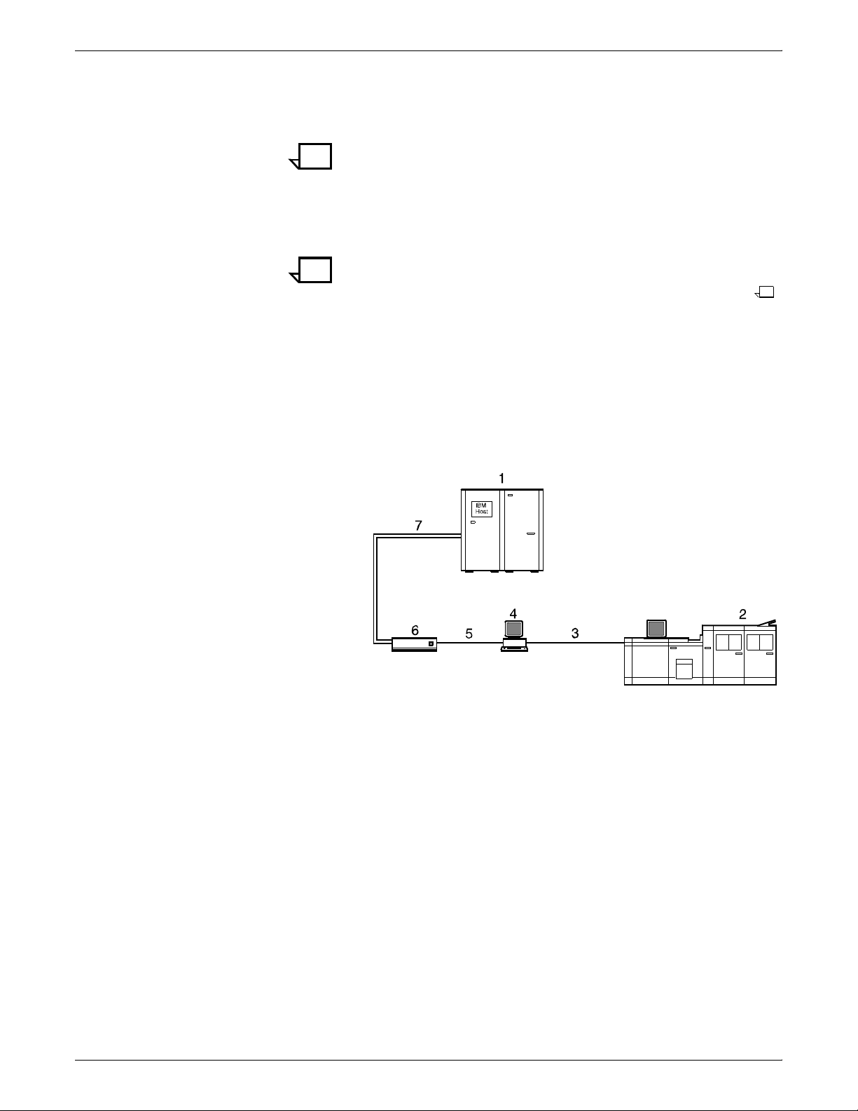
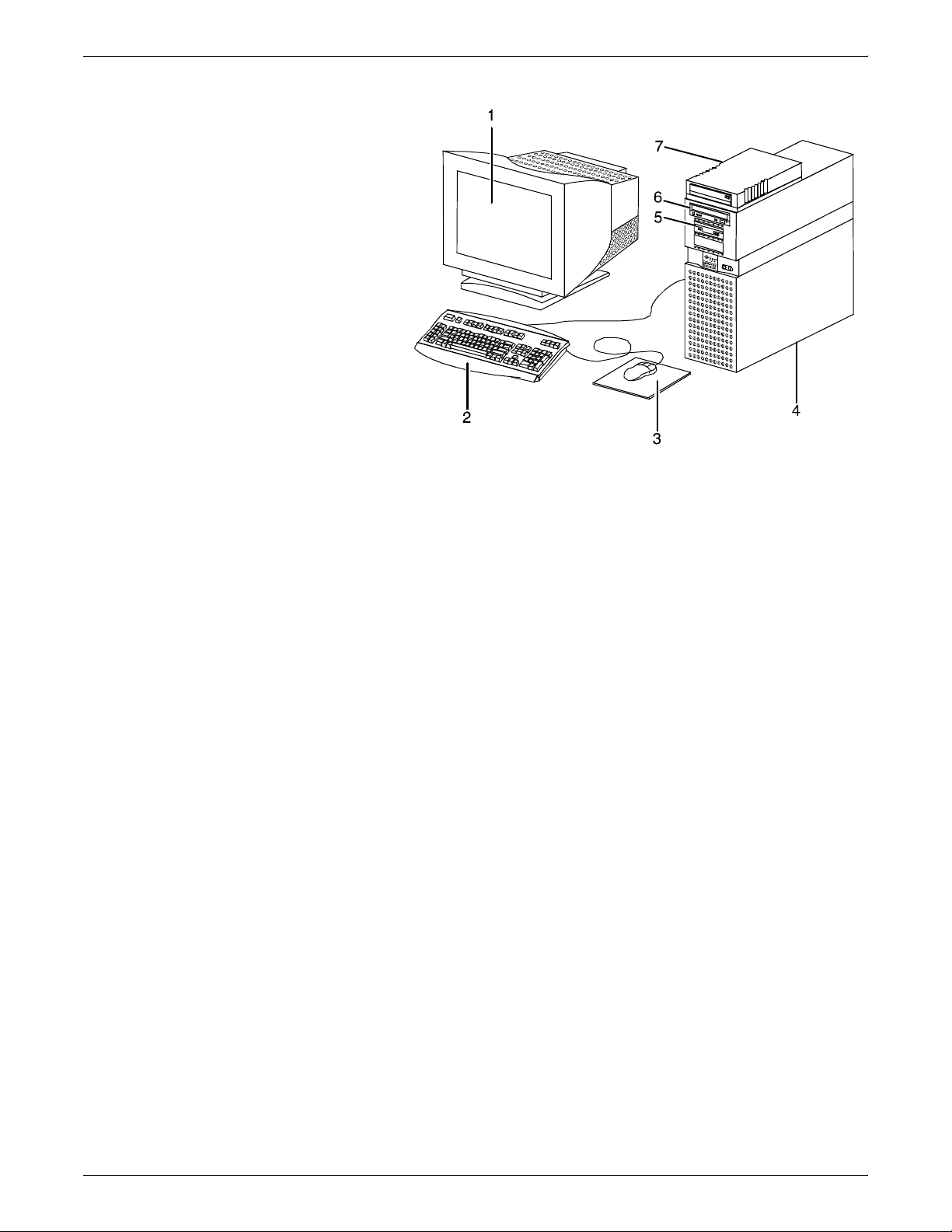
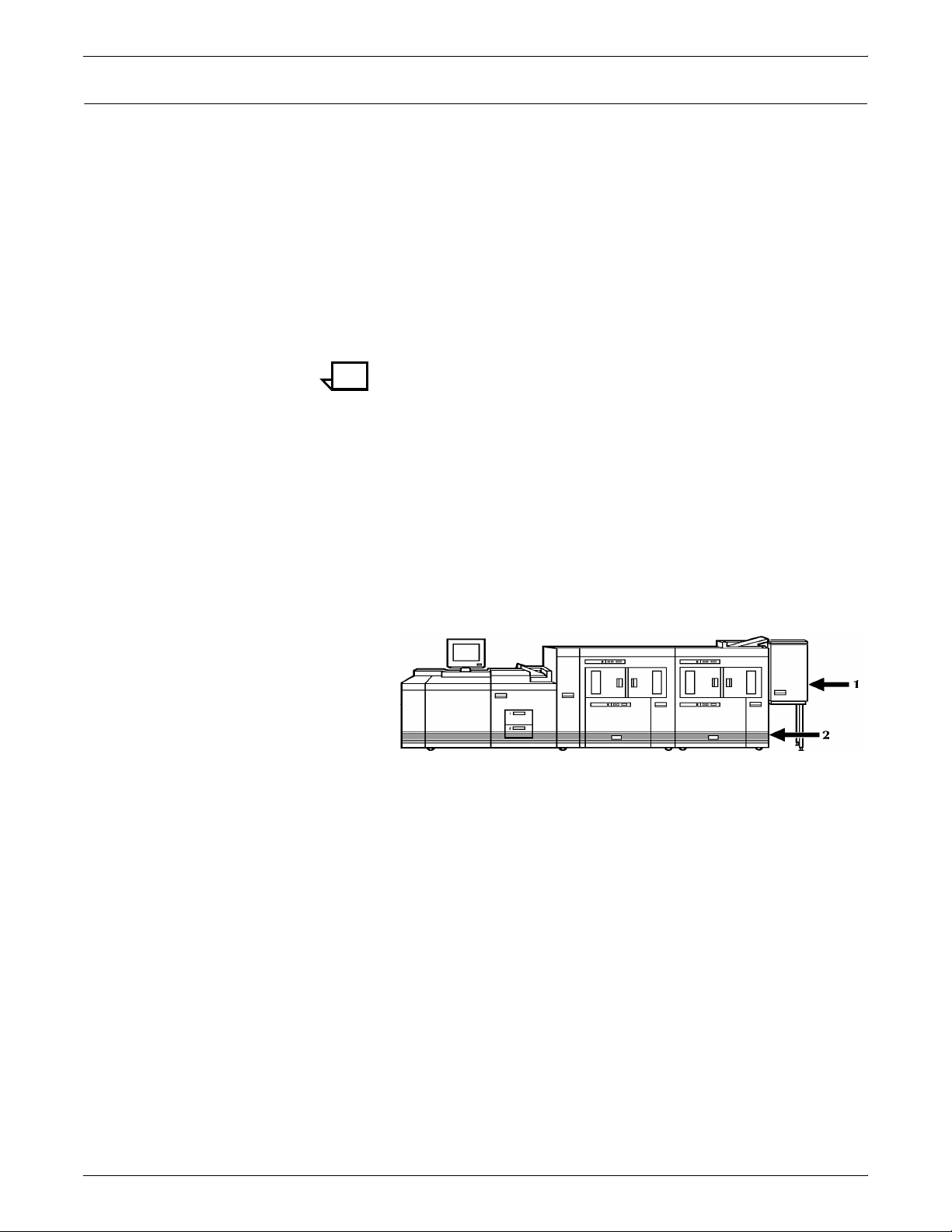
Figure 1-1. Xerox 96/4635/180 IPS: Channel-attached
configuration
1 Host system (PC or mainframe)
2 96, 4635, or 180 IPS printer
3 Printer interface cable (DCIM2)
4 Sun workstation controller
5 SCSI interface
6 Host Channel Unit (HCU)
7 Bus and tag cables
1-2 XEROX DOCUPRINT 96/4635/180 IPS INSTALLATION PLANNING GUIDE
Page 15
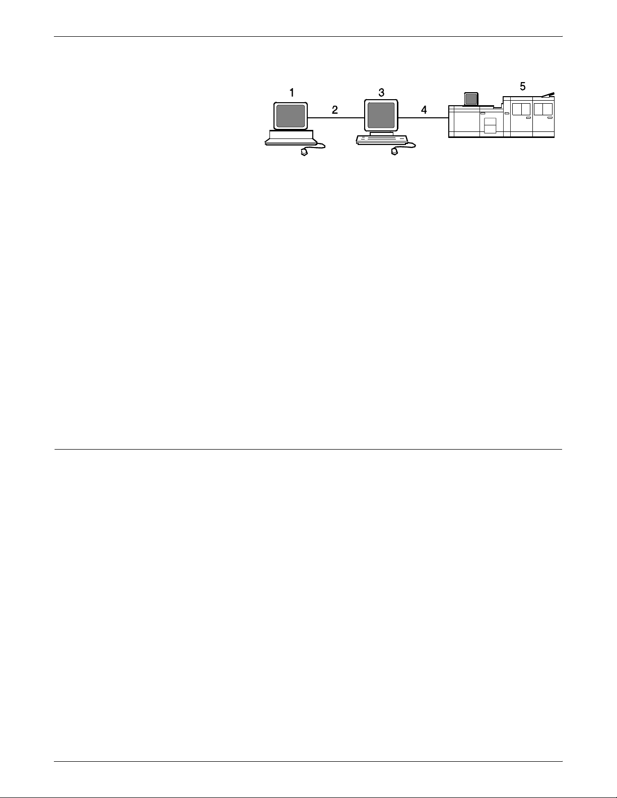
Figure 1-2. 96/4635/180 IPS: TCP/IP configuration
1 Host system (PC or mainframe)
2 Token Ring or Ethernet network connection
3 Sun workstation controller
4 Printer interface cable (DCIM2)
5 96, 4635, or 180 IPS printer
For information on the various IPS printer configuration options, refer
to the “Printer components and options” chapter of this guide.
Throughput speed Data is printed at high speeds:
• 96 and 96 MICR IPS: Up to 96 pages per minute
• 4635 and 4635 MICR IPS: Up to 135 pages per minute.
• 180 and 180 MICR IPS: Up to 180 pages per minute
PRODUCT OVERVIEW
Monthly print volume The monthly print volumes for these systems are:
System components
• 96 and 96 MICR IPS: Up to 3 million pages
• 4635 and 4635 MICR IPS: Up to 4 million pages
• 180 and 180 MICR IPS: Up to 6 million pages
The IPS systems consist of the following major components:
• Printer controller — The printer controller (also called the
system controller) accepts IPDS data (plus PostScript and PCL
data with the Dual Mode option) from the host, processes the
data, and sends the data to the printer engine using the IPS
operating system. The controller provides the printer with print
data and commands, and receives status information from the
printer.
• Printer — The printer, also called the Image Output Terminal
(IOT), accepts formatted pages of data from the printer
controller and performs the imaging and printing of documents.
The printer also provides paper stacking, collating, and optional
finishing capabilities you enable using the IPS application
software accessed through the graphical user interface.
XEROX DOCUPRINT 96/4635/180 IPS INSTALLATION PLANNING GUIDE 1-3
Page 16

PRODUCT OVERVIEW
System features
The 96/4635/180 IPS provides numerous features that can be
enabled or configured using the graphical user interface on the
printer controller.
• Multiple input trays — Multiple feeder trays can be configured
to feed paper for jobs in the most effective manner. For
example, the trays can provide nonstop printing of a complex
job that requires many paper stocks, or only a few stocks, by
using the trays’ continuous loading capability. A different input
tray can also be selected for each copy of a specific page in a
print job, for example, to provide different paper colors for
specific pages.
— 96 IPS: Three addressable input trays are standard with
the system, and one additional tray is available as an
option.
— 4635 and 180 IPS: Four addressable input trays are
standard with the system, and two additional trays are
available as options.
Feeder tray capacities, based on 20-pound or 80 gsm (grams
per square meter) bond, are:
— Tray 1: 1,100 sheets
— Tray 2: 600 sheets
— Trays 3 and 4: 2,600 sheets
— Optional trays (5 and 6): 2,600 sheets each.
• Roll feeder support — The 96, 4635, and 180 IPS can each
accommodate a third-party roll feeder as an input tray. (Refer to
your local Xerox sales representative for information on thirdparty roll feeders.)
— The 96 and 4635 IPS have an optional configuration in
which the roll feeder interfaces with the last feeder/stacker
module. With this configuration, the 4635 IPS may have up
to six feeder trays, with the sixth being the roll feeder. The
96 IPS may have up to five input trays, with the roll feeder
as the fifth.
Note: To be able to use this roll feeder option on the
96/4635 IPS, you must have the Input Enablement kit
installed. (Refer to the “Printer components and options”
chapter of this guide.)
— The roll feeder option for the 180 IPS is installed in the
inverter feeder/stacker module, replacing the feeder tray. It
does not require the Input Enablement kit or DFA software.
The maximum number of feeder/stacker modules
supported for this configuration is four, including the
inverter module with the roll feeder. With the two processor
feeder trays, this makes a total of six input trays possible.
• Advanced paper handling — The 96/4635/180 IPS can
handle paper stock ranging in size from 8 by 10 inches / 203 by
254 mm to 14 by 17 inches / 356 by 432 mm, including sizes A3
and A4.
1-4 XEROX DOCUPRINT 96/4635/180 IPS INSTALLATION PLANNING GUIDE
Page 17
PRODUCT OVERVIEW
The DP96, DP4635 and DP180 IPS can also print on papers as
small as 7 by 10 inches / 178 by 254 mm, with the optional 7 by
10-inch kit. They process paper weights from 16-pound / 60
gsm to 110-pound / 200 gsm.
Jobs also can be printed on label stock, transparencies,
precollated stock, tab stock, carbonless paper, and other
specialized stocks. The printer engine monitors the print job so
that, should a paper jam occur, the job resumes on the correct
page, at the correct tab, using the same color paper, etc.,
providing complete document integrity.
• Mixes plex feature — The 96/4635/180 IPS can switch from
duplex to simplex printing, and vice versa, without cycling down
the printer. The IPS system starts the first job in the plex mode
of the first sheet received. If the mode is duplex and a
subsequent sheet received is simplex, blank backs are used.
This continues until the consecutive simplex threshold is
reached. Once reached, the system starts printing in simplex,
after clearing the paper path of all duplex sheets. When the next
duplex page is received, the system starts printing in duplex,
without shutting down. The process starts over, printing simplex
pages in duplex mode using blank backs, until the consecutive
simplex threshold is reached.
• 600 dpi resolution — The 96, 4635, and 180 IPS all print at
high resolution. The printers can receive data at 240 or 300 dpi
(dots per inch) and full-page IOCA images at 600 dpi. All 240 or
300 dpi data is then interpolated to 600 dpi for higher print
quality.
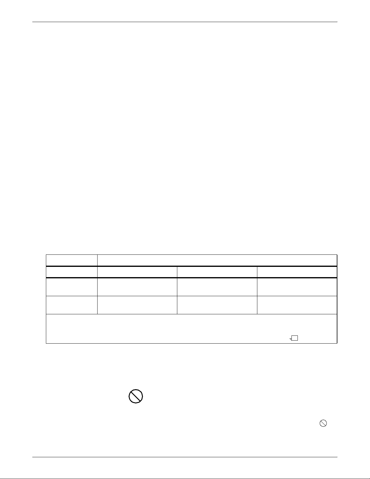
The following table shows how data streams of different
resolutions are interpolated.
Table 1-1.Data stream conversion to 600 dpi
Incoming input resolution of document
Printer 240 dpi data 300 dpi data 600 dpi data*
180 IPS Interpolated by printer to
600 x 2400 dpi.**
96 and 4635 IPS Converted by controller to
600 dpi.
* Full-page IOCA images only
**Note: This is an option on the 180 IPS, requiring a special board to be installed by your service
representative. Without this board, 240 dpi data is converted to 600 dpi by the controller.
Interpolated by printer to
600 x 2400 dpi
Interpolated by printer to
600 x 600 dpi
For the 96/4635/180 IPS and the 96/4635/180 MICR IPS
systems it is recommended that all fonts and other resources
that are at 240 dpi be converted to 300 dpi before printing,
rather than leaving the conversion for the controller to do. This
ensures better print quality.
Caution: The 96/4635/180 IPS must have the same font
resolution specified as the host input data stream (refer to the
Guide to Configuring and Managing the System for instructions
on specifying the input resolution). Conflicts between the input
font resolution and the IPS specification could result in inability
to print the job, or in missing variable data in the output.
Print at 600 x 2400 dpi
Print at 600 x 600 dpi
XEROX DOCUPRINT 96/4635/180 IPS INSTALLATION PLANNING GUIDE 1-5
Page 18

PRODUCT OVERVIEW
• Multiple high-capacity output bins — Each output bin has
offsetting capability and a capacity of 2500 sheets of 20-pound
or 80 gsm bond.
Note: This capacity does not apply to 11 by 17-inch and A3
papers. Because of the additional weight these large sheets add
to the bins, each bin can hold only up to 1500 sheets of A3 or 11
by 17-inch papers.
— 96 IPS: One output bin is standard for the system, with one
additional bin available as an option (providing up to two
bins total).
— 4635 and 180 IPS: Two output bins are standard, with up
to two additional bins available as options (providing up to
four bins total).
• Bypass transport option — The bypass transport enables
sheets to pass through the printer output module to a thirdparty finishing device. With such devices, you can add to your
96/4635/180 IPS such finishing capabilities as saddle-stitching,
binding, trimming, etc. The bypass transport is installed at the
right (as you face the printer) of the last feeder/stacker module
on your system. The bypass transport cannot be installed on
systems with more than three feeder/stacker modules. (For
more information on the bypass transport, refer to the “Printer
components and options” chapter of this guide.)
NPS/IPS Dual Mode
The Xerox DocuPrint Dual Mode option enables both DocuPrint IPS
and NPS systems to coexist on the same printer controller (Sun
workstation). This allows the DocuPrint system to receive data
streams supported by NPS and IPS, including IPDS, PostScript
Levels 1 and 2, HP PCL5c, HP PCL5e, and ASCII.
Either of the following two types of configurations may be used:
• The same Token Ring or Ethernet connection can be used for
both IPDS (IPS) and Postscript/PCL (NPS).
• Both a Token Ring card and an Ethernet card can reside in the
Sun workstation controller, with one being used for IPDS and
the other for PostScript/PCL.
The customer may switch from one mode to the other. When your
system is operating in IPS mode, it can accept PostScript and PCL
data streams in the background; however, you can print these jobs
only when the system is in NPS mode. When in NPS mode, the
system cannot accept IPDS data streams in the background; you can
print them only when the system is in IPS mode.
Refer to the Xerox DocuPrint IPS/NPS Dual Mode Switching
Instructions and other Xerox DocuPrint IPS documentation for more
information.
1-6 XEROX DOCUPRINT 96/4635/180 IPS INSTALLATION PLANNING GUIDE
Page 19
MICR printing features
PRODUCT OVERVIEW
The DocuPrint 96 MICR, 4635 MICR, and 180 MICR IPS produce a
Magnetic Ink Character Recognition (MICR) line on negotiable and
turnaround documents such as checks and bills. The MICR printing
systems print documents using magnetic ink and special fonts to
create machine readable information that allows for quick document
processing.
In general, MICR is used to print accounting and routing information
on blank checks and other negotiable documents. The magnetic
encoding capabilities can be used for any printed output.
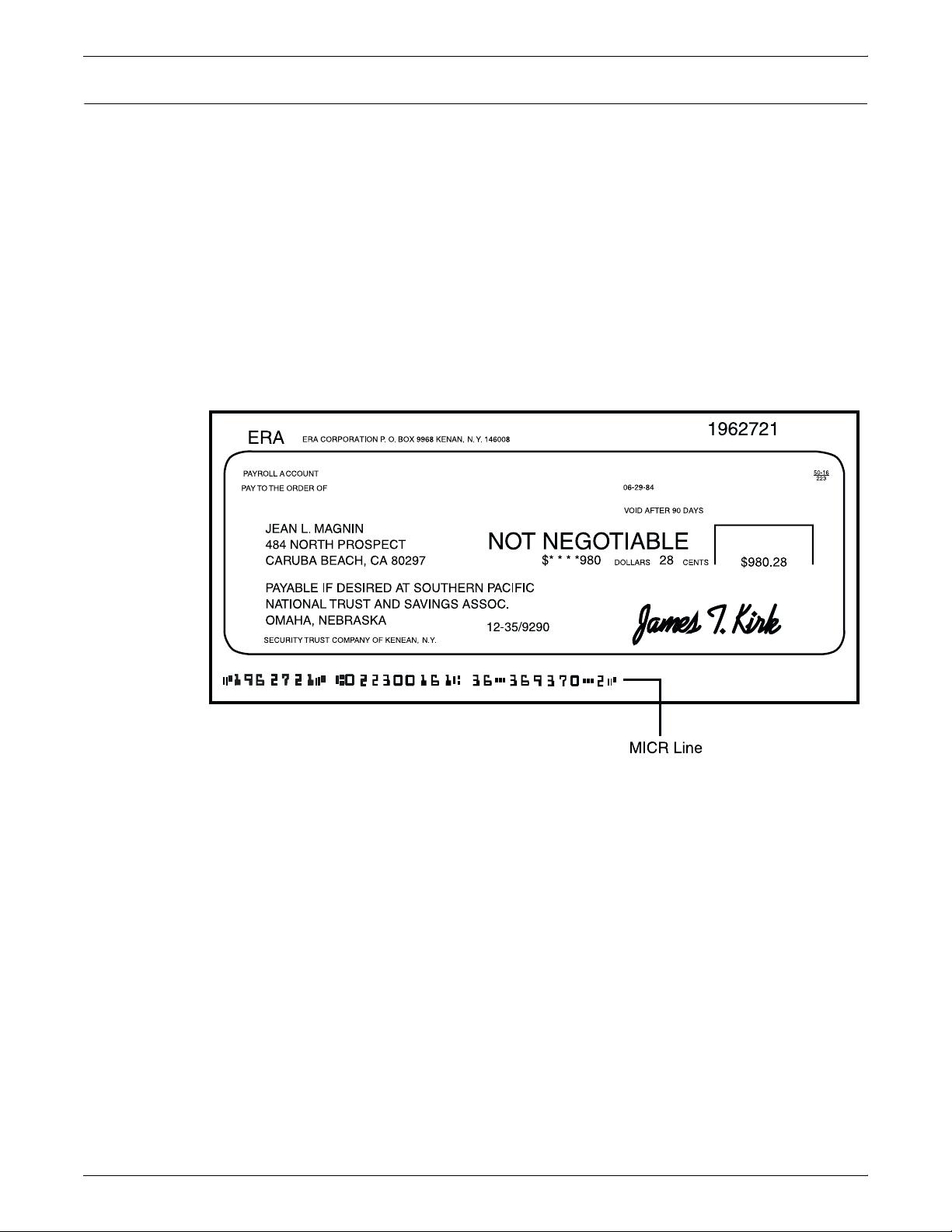
The following illustrates a check printed with a MICR line in U.S.
format. The entire MICR line, which consists of numbers and
characters (called symbols), is printed using magnetic ink.
Figure 1-3. Example of a check printed with MICR line (U. S.)
The 96 MICR, 4635 MICR, and 180 MICR IPS meet ABA standards
and ANSI and ISO specifications for automatic check handling. They
print the variable data and the MICR line at the same time. This
single-pass printing capability reduces processing time and costs.
Unsupported features The DocuPrint 96 MICR, 4635 MICR, and 180 MICR IPS do not
support the security and audit feature or bar code reading. In
addition, although the Line Thickening selection and the Virtual
Printer Imaging parameters are available when you use MICR, it is
not recommended that you use these features when printing MICR
documents as they corrupt the MICR line.
In general, all print quality adjustments and enhancement settings
should be set at the nominal settings when printing MICR output.
XEROX DOCUPRINT 96/4635/180 IPS INSTALLATION PLANNING GUIDE 1-7
Page 20

PRODUCT OVERVIEW
MICR fonts Xerox provides a set of 300 dpi E13B and CMC7 MICR fonts for use
with your 96/4635/180 MICR IPS. To receive the high print quality
guaranteed by Xerox, you must use these MICR fonts.
E13B fonts: The E13B font series includes the following:
• E13B
• E13B Landscape
• E13B Test
• E13B Test Landscape.
CMC7 fonts: CMC7 fonts have been adopted in various countries
outside of the U.S., and are the official standard in France. Like the
E13B font, they are magnetically readable, but with a different
character design and recognition criteria. (Currently, CMC7 is
available only through Xerox Ltd. of Europe.)
The CMC7 series includes:
• CMC7
• CMC7 Landscape
• CMC7 Test
• CMC7 Test Landscape
The “Test” fonts are non-readable MICR hollow bitmap (or outline)
fonts, provided for testing MICR applications and printing nonnegotiable documents.
Sixth Sense
Sixth Sense is a unique suite of diagnostic tools that allows Xerox
customer service engineers, analysts, and consultants to serve
customers more effectively.
Sixth Sense is intended to automate and expedite the range of
service-related support functions. Sixth Sense is a tool that enables
Xerox to provide benchmark service support. Xerox customers
benefit from the ability to bring broader support to focus more quickly.
For example, Sixth Sense can allow the Service Representative to
repeatedly “preview” the condition of the system prior to an actual
site visit. This may provide the ability to determine the correct part or
piece of information to have on hand when the site visit is made.
Sixth Sense is a no charge feature available to customers through
Xerox Service. The customer need only provide an analog phone line
for use by the Sixth Sense modem connection. For those customers
unable to dedicate a phone line to the Sixth Sense connection, three
and five port phone share devices are available for purchase. (Refer
to your local Xerox sales representative for further information.)
To take advantage of Sixth Sense, the customer needs to:
• Request Sixth Sense enablement through Xerox Service
• Provide an analog phone line
• Provide a 120V outlet in which to plug a modem
• If necessary, purchase an optional phone share device.
More information about Sixth Sense can be found in the Xerox
DocuPrint IPS 96/4635/180 Troubleshooting Guide.
1-8 XEROX DOCUPRINT 96/4635/180 IPS INSTALLATION PLANNING GUIDE
Page 21

Controller hardware
2. 2Controller components and
options
The printer controller provides the printer with print data and
commands, and receives status information from the printer. This
chapter describes the components and options available for the
controller.
The printer controller consists of a Sun workstation and, if you are
printing data received over a channel, a Host Channel Unit (HCU).
The controller uses proprietary Xerox hardware, firmware, and
software to run the IPS.
Your controller may be either a Sun Ultra 2 or Ultra 60 workstation.
The following sections contain information about both the Ultra 2 and
the Ultra 60.
Sun Ultra 2 workstation
The Sun workstation provides a user interface to the print engine. It
is used to operate the IPS software that controls the printer. The
workstation contains the following hardware components:
• Sun Ultra 2 workstation processor (system unit)
• Display monitor
• Keyboard and mouse
• Connectivity boards for Ethernet and, optionally, Token Ring
• A Data Control Interface Module (DCIM2) card installed in the
processor to interface with the print engine.
XEROX DOCUPRINT 96/4635/180 IPS INSTALLATION PLANNING GUIDE 2-1
Page 22
CONTROLLER COMPONENTS AND OPTIONS
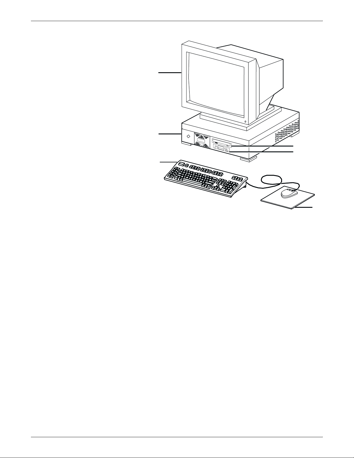
Figure 2-1. Components of the Sun Ultra 2 workstation
2
1
6
5
4
3
1 Processor
2 Monitor
3 Mouse and mouse pad
4 Keyboard
5 Diskette drive
6 CD-ROM drive
Processor The 256 MB RAM processor is the central processing unit of the Sun
workstation. It contains a power switch, an internal disk drive, a
diskette drive, a CD-ROM drive, a power receptacle and outlet,
connectors and ports.
The processor has the following components:
• Internal disk drive: One 4.2 GB internal disk drive is provided
as a standard feature of the processor. The operating system,
the IPS application, and any queued print jobs are stored on the
internal disk. This disk cannot be used to store other
applications or data except as directed by your service
representative. Up to three optional disk drives are available in
increments of 4 or 9 GB.
• Diskette drive: Diskettes inserted into a diskette drive are used
to load files to, and back up files from, the internal disk drive.
The diskette drive uses industry standard 3.5 inch, 1.44 MB,
double-sided, high-density diskettes. This diskette drive is not
an input source for print jobs nor any other data or application; it
is reserved exclusively for use by a service representative to
update software and to store files. The diskette drive is located
in the processor, on the right front section for the Ultra 2.
2-2 XEROX DOCUPRINT 96/4635/180 IPS INSTALLATION PLANNING GUIDE
Page 23
CONTROLLER COMPONENTS AND OPTIONS
• CD-ROM drive: The CD-ROM drive is a high density, read-only,
optical laser storage device used for loading the IPS operating
system and other files. The CD-ROM drive is located in the
processor above the diskette drive.
• Cartridge tape drive (not shown): An optional 8 GB, 4 mm
SCSI cartridge tape drive also is available for the IPS. Like the
diskette and CD drives, this tape drive is not an input source for
print jobs or for any other data or application. It provides the
service representative with another means of loading system
maintenance files or saving diagnostic information.
Caution: When installing a cartridge drive on an IPS with a
host channel unit (HCU), the tape drive must be “daisy-chained”
to the HCU. In this situation, do not attempt to run both the tape
drive and the HCU at the same time.
• Back panel: The back panel of the processor has a power
switch, a power receptacle and outlet, connectors, connector
openings, and ports. The following figure shows the back panel
of the Sun workstation that is a part of your IPS controller.
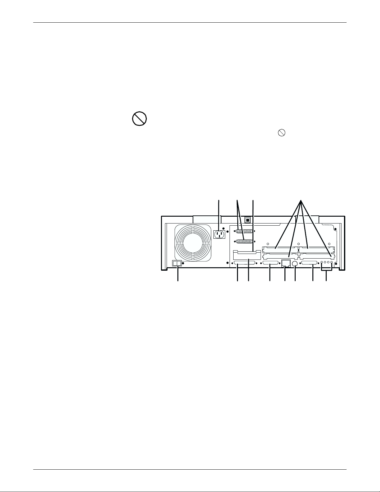
Figure 2-2. Back panel of the Sun Ultra 2 processor
11
3
2
3
2
10
9
4
1
0
8
7
5
6
1
12
1 Power inlet
2 Serial connectors (2): RS-432/RS-232
3 Graphics/video output: UPA slot
4 Sbus slots (Number of slots varies depending on the model)
5 Audio connectors (4)
6 Parallel connector
7 Keyboard/mouse connector
8 TPE connector
9 MII connector
10 UPA slot
11 SCSI connector
12 Power on/Standby switch
Display monitor The display monitor has a 1192 x 700 pixel screen which displays the
IPS graphical user interface windows.
XEROX DOCUPRINT 96/4635/180 IPS INSTALLATION PLANNING GUIDE 2-3
Page 24

CONTROLLER COMPONENTS AND OPTIONS
Keyboard The keyboard consists of alphanumeric keys similar to a typewriter,
Mouse The mouse is another main method of communicating with the
Sun Ultra 60 workstation
symbols and special character keys, an extended character set, and
function keys. The keyboard is one of your main methods of
communicating with the printer. You can use the keyboard to make
selections, and to enter commands that control functions such as
requesting sample prints, obtaining billing meter totals, shutting down
the system, and so forth.
printer. The mouse has three buttons. The left and right buttons are
used to select IPS functions. The center button provides additional
functions that you will not be required to use. If your workstation has
an optical mouse, it must remain on its designated metallic pad to be
active. If the mouse has a roller ball instead of an optical sensor
underneath, it requires a non-metallic pad.
Note: Printer controller hardware configurations are subject to
upgrade.
The Sun Ultra 60 workstation provides a user interface to the print
engine. It has a high performance RISC processor chipset, based on
the industry standard Scalable Processor Architecture (SPARC). It is
used to operate the software that controls the printer. The
workstation contains the following hardware components:
• Sun Ultra 60 workstation processor (system unit)
• Display monitor
• Keyboard and mouse
• Diskette, CD-ROM, and cartridge tape drives
• Connectivity board for Ethernet and, optionally, Token Ring
• A Data Control Interface Module (PDCIMu) card installed in the
processor to interface with the print engine.
2-4 XEROX DOCUPRINT 96/4635/180 IPS INSTALLATION PLANNING GUIDE
Page 25
CONTROLLER COMPONENTS AND OPTIONS
Figure 2-3. Components of the Sun Ultra 60 workstation
1 Monitor
2 Keyboard
3 Mouse
4 Processor
5 Diskette drive
6 CD-ROM drive
7 Cartridge tape drive
Processor The 256 MB RAM processor is the central processing unit of the Sun
Ultra 60 workstation. It contains a power switch, a disk drive, a
diskette drive, a CD-ROM drive, a power receptacle and outlet,
connectors and ports.
The processor has the following components:
• Internal disk drive: Two 18.2 GB primary disk drives are
provided as a standard feature of the processor. The operating
system, the IPS application, and any queued print jobs are
stored on the internal disk. This disk cannot be used to store
other applications or data except as directed by your service
representative.
• Diskette drive: Diskettes inserted into a diskette drive are used
to load files to, and back up files from, the internal disk drive.
The diskette drive uses industry standard 3.5 inch, 1.44 MB,
double-sided, high-density diskettes. This diskette drive is not
an input source for print jobs nor any other data or application; it
is reserved exclusively for use by a service representative to
update software and to store files.
• CD-ROM drive: The CD-ROM drive is a high density, read-only,
optical laser storage device used for loading the IPS operating
system and other files. The CD-ROM drive is located in the
processor above the diskette drive.
XEROX DOCUPRINT 96/4635/180 IPS INSTALLATION PLANNING GUIDE 2-5
Page 26
CONTROLLER COMPONENTS AND OPTIONS
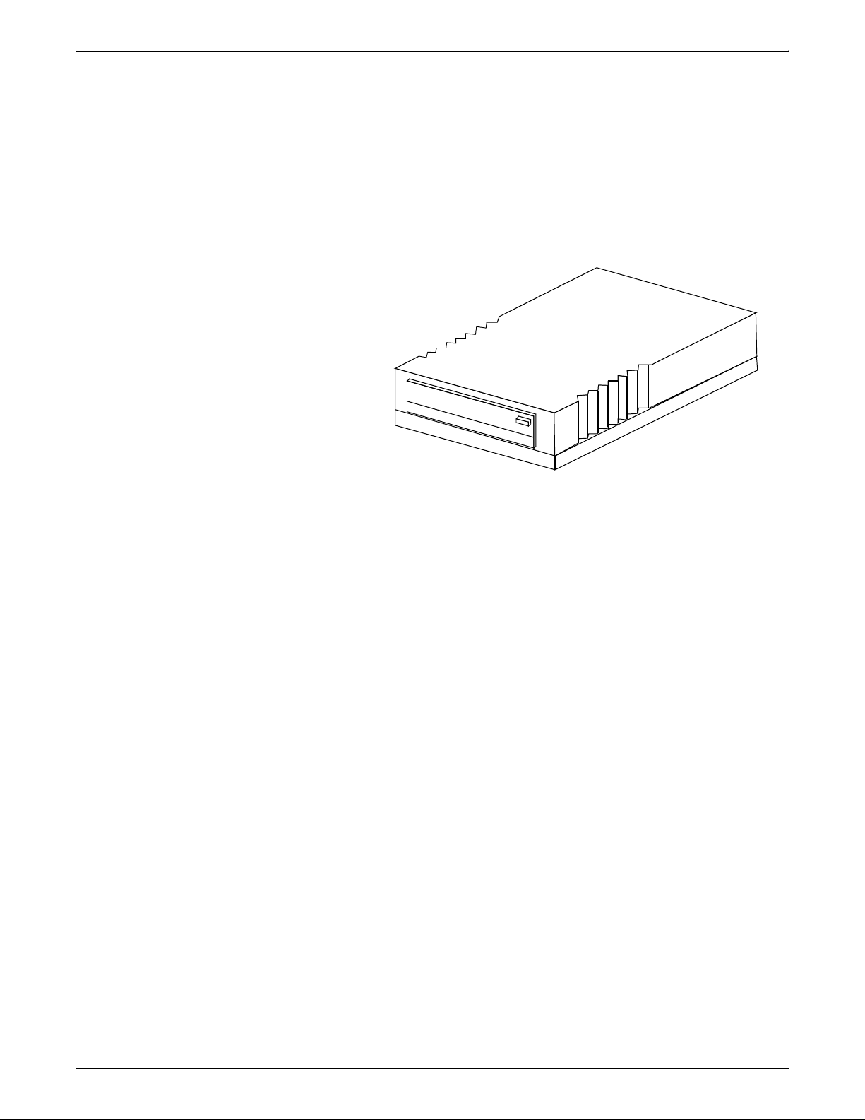
• Cartridge tape drive: A 4 GB external SCSI quarter inch
cartridge (QIC) tape drive is an external device provided with
the printing system. The cartridge tape drive connects to the
controller through the SCSI port on the processor back panel.
Like the diskette and CD drives, this tape drive is not an input
source for print jobs or for any other data or application. You
use it to load resource files, and the service representative uses
it to load system maintenance files or to save diagnostic
information.
Figure 2-4. External cartridge tape drive
• Back panel: The back panel of the processor has a power
receptacle and outlet, connectors, connector openings, and
ports. The following figure shows the back panel of the Sun
Ultra 60 workstation that is a part of your IPS controller.
2-6 XEROX DOCUPRINT 96/4635/180 IPS INSTALLATION PLANNING GUIDE
Page 27
CONTROLLER COMPONENTS AND OPTIONS
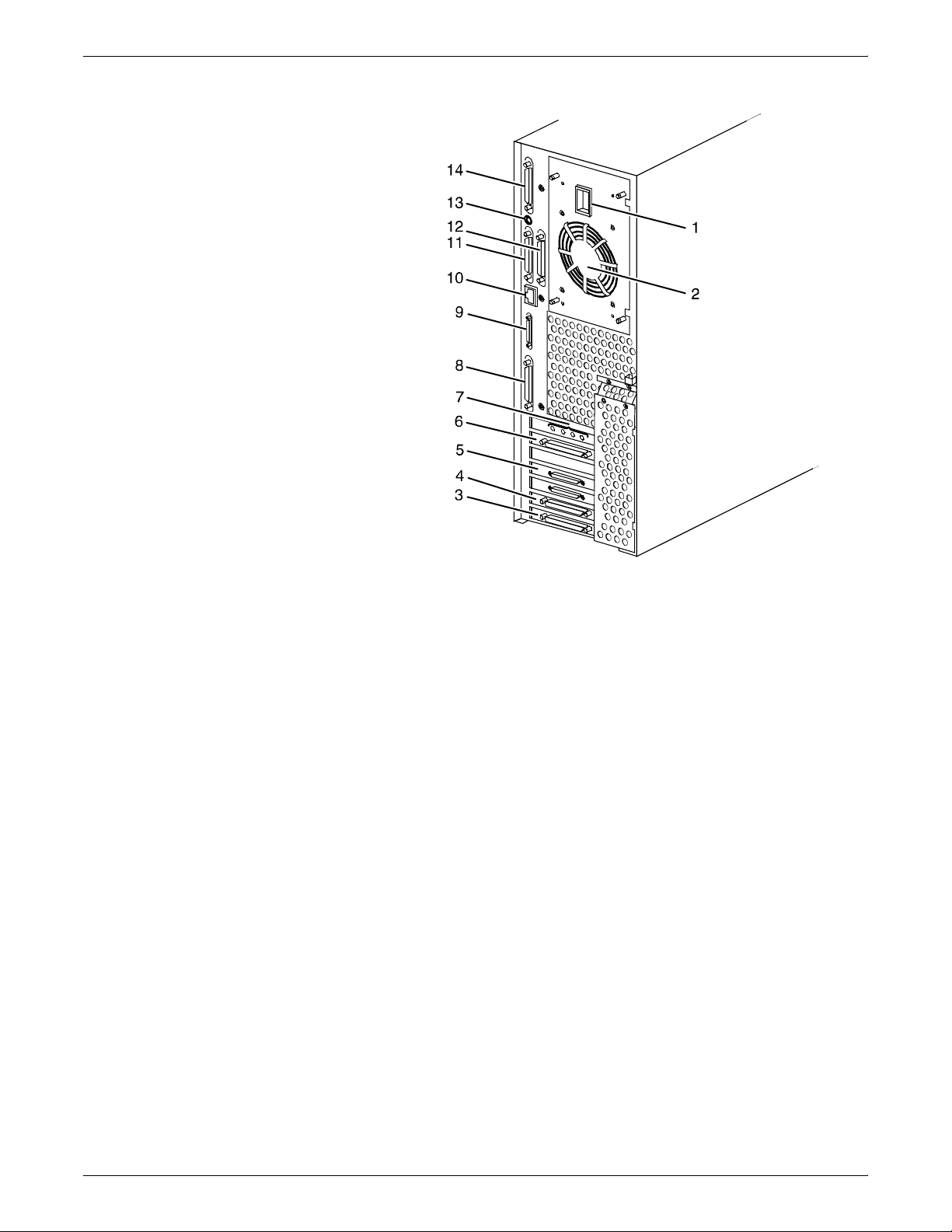
Figure 2-5. Back panel of the Sun Ultra 60 processor
1 Power inlet
2 Fan vent
3 Online interface (if configured)
4 Differential SCSI PWB (optional)
5 Printer connector (PCI66 1)
6 Monitor connector
7 Audio connectors (4)
8 Single-ended SCSI connector
9 MII connector
10 TPE (Ethernet) connector
11 Serial connector A: RS-432/RS-232
12 Serial connector B: RS-432/RS-232
13 Keyboard connector
14 Parallel connector
Display monitor The graphical user interface allows you to interact with the printer
and to monitor its interaction with the various components. During a
print job, printer error messages may display to notify you of any
unexpected conditions.
Keyboard The keyboard consists of alphanumeric keys similar to a typewriter,
symbols and special character keys, an extended character set, and
function keys. The keyboard is one of your main methods of
communicating with the printer. You can use the keyboard to make
selections, and to enter commands that control functions such as
requesting sample prints, obtaining billing meter totals, shutting down
the system, and so forth.
XEROX DOCUPRINT 96/4635/180 IPS INSTALLATION PLANNING GUIDE 2-7
Page 28

CONTROLLER COMPONENTS AND OPTIONS
Mouse The mouse is another main method of communicating with the
IPS user interface screen
printer. The mouse has three buttons. The left and right buttons are
used to select IPS functions. The center button provides additional
functions that you will not be required to use. If your workstation has
an optical mouse, it must remain on its designated metallic pad to be
active. If the mouse has a roller ball instead of an optical sensor
underneath, it requires a non-metallic pad.
Note: Printer controller hardware configurations are subject to
upgrade.
The graphical user interface allows you to interact with the printer
and to monitor its interaction with the various components. During a
print job, printer error messages may display to notify you of any
unexpected conditions.
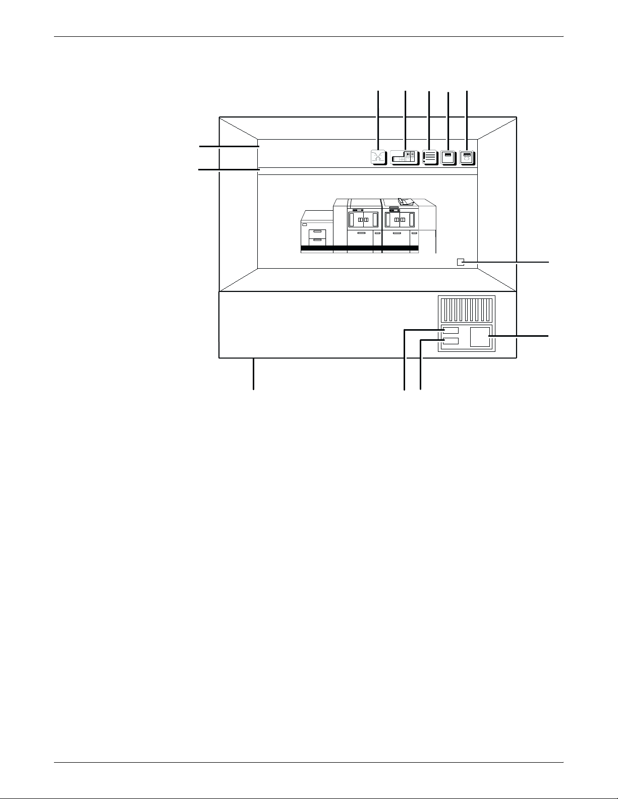
Note: The following figure shows the user interface screen with the
main window for a 96 MICR IPS. The main windows for the 180 IPS
and the 4635 IPS are identical to this one, except that they do not
display the MICR On/Off field in the Control Unit Configuration
section (upper-right corner). The 4635 MICR IPS and 180 MICR IPS
main windows differ only in the number of output bin icons they can
display in the Output section.
2-8 XEROX DOCUPRINT 96/4635/180 IPS INSTALLATION PLANNING GUIDE
Page 29
CONTROLLER COMPONENTS AND OPTIONS
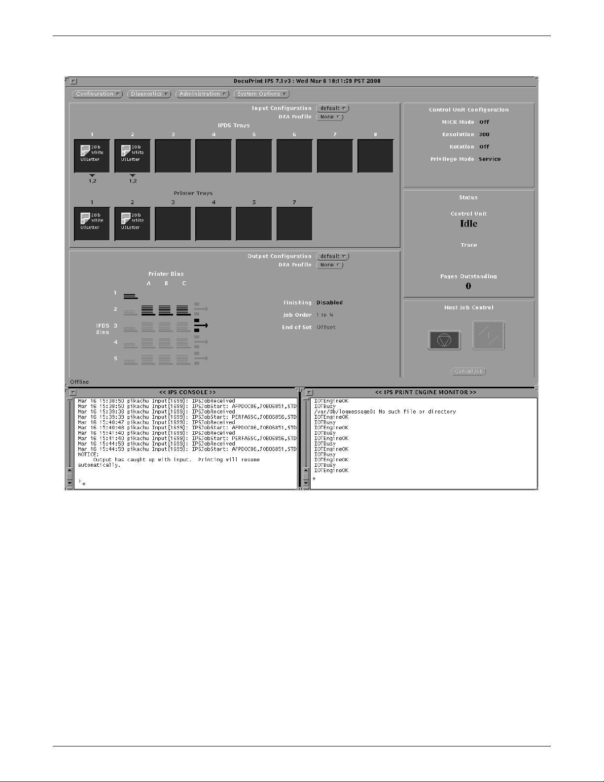
Figure 2-6. IPS user interface screen
The IPS console window displays the system messages. The IPS
print engine monitor window monitors the current printer state and
displays messages such as a broken or jammed printer, printer
ready, paper trays, engine faults, and other messages about the
condition of the printer.
The IPS main window provides access to the IPS menus and tray
grouping windows. These menus and windows in turn provide
access to the task subwindows from which system operation and
administration tasks are performed.
XEROX DOCUPRINT 96/4635/180 IPS INSTALLATION PLANNING GUIDE 2-9
Page 30
CONTROLLER COMPONENTS AND OPTIONS
Host Channel Unit—channel-attached systems only
The Host Channel Unit (HCU) handles all of the IPDS
communications and handshaking with PSF on the host when the
IPS is receiving data over a channel. (It is not used when the IPS is
printing data using TCP/IP.) The following figure illustrates the HCU
component.
Figure 2-7. Host Channel Unit (HCU)
• The front panel of the HCU provides a single-digit LED display
which enables you to monitor power-up and offline status, and
alerts you to error conditions. (Refer to the IPS Messages
Guide for an explanation of the HCU codes displayed here.)
• The back panel of the HCU has a power switch and outlet,
S/370 bus and tag cable input and bypass connectors, and a
dual serial port. In addition, there are two switches on the back
panel to set channel priority to high or low. The power supply is
a standard switching power supply capable of 10 amps on the 5
volt output.
Note: The customer is responsible for obtaining, stringing, and
maintenance of the bus and tag cables. The bus and tag cables must
be fully populated cable sets.
2-10 XEROX DOCUPRINT 96/4635/180 IPS INSTALLATION PLANNING GUIDE
Page 31

Printer components
3. 3Printer components and
options
The printer processes the electronic data and images received from
the controller and produces the printed report. This chapter
describes the components and options available for the printer.
The standard 96, 4635, and 180 printer components are the printer
control console, the sample tray, the purge tray, the two processor
feeder trays, and the feeder/stacker module(s).
• 4635 and 180: The base configuration for the 4635 and 180
includes an inverter feeder/stacker and one additional feeder/
stacker module.
• 96: The 96 base printer configuration contains only the inverter
feeder/stacker module. An additional feeder/stacker (as
illustrated below) is an option.
Figure 3-1. Printer base components
1
765
1 Printer control console
2 Sample tray
3 Attention light
4 Purge tray
5 Feeder/stacker module (optional on 96)
6 Inverter feeder/stacker module
7 Processor feeder trays
32
4
The printer provides control buttons and displays for basic printer
functions and status information. The printer control console contains
message and graphic displays that assist you with jam clearance and
printer maintenance. Labels are located throughout the printer to
assist you with a variety of tasks such as clearing a paper jam.
XEROX DOCUPRINT 96/4635/180 IPS INSTALLATION PLANNING GUIDE 3-1
Page 32

PRINTER COMPONENTS AND OPTIONS
Printer control console
Refer to the System Overview manual for a detailed description of
the features and operation of the printer components.
The printer control console is the color monitor located on top of the
printer. It contains message areas and graphic displays that alert you
to paper jams and other fault and status conditions (such as low dry
ink). It also contains buttons which allow you to control certain
functions of the printer (for example, continuing an interrupted job)
without returning to the workstation controller.
The printer control console has the following features:
• Local controls and displays for jam clearance, paper loading/
unloading, and diagnostics/service (used by the service
representative). Two types of messages are displayed on the
printer control console: fault messages, which relate to printer
malfunctions, and information messages, which relate to printer
conditions such as low dry ink.
• Touch-sensitive areas that allow you to select options by
touching the printer control console screen. A tone sounds
when you touch one of these areas.
• Attention alarm tone consisting of three beeps, repeated for
ten seconds. The alarm is generated by any event that stops
the printer and requires operator attention. The alarm may be
disabled by the operator.
The tone stops after three cycles, or when the fault condition is
cleared or clearing has started (for example, doors or covers
specified in the clearance instructions are opened). You can
stop the tone by pressing one of the printer control console
buttons or by selecting a function through the touch screen.
3-2 XEROX DOCUPRINT 96/4635/180 IPS INSTALLATION PLANNING GUIDE
Page 33
PRINTER COMPONENTS AND OPTIONS
Figure 3-2. Printer control console
1
2345
12
11
Ready
Printer Options
10
1 Language icon
2 Printer icon
3 Fault List icon
4 Tools icon
5 Guarded Tools icon
6 Clear button
7 Continue button
8 Stop button
9 Sample button
10 Brightness control thumbwheel
11 Icon area
12 Message area
Clear
6
7
8
9
Refer to the System Overview manual for a detailed description of
the features and operation of the printer control console components.
XEROX DOCUPRINT 96/4635/180 IPS INSTALLATION PLANNING GUIDE 3-3
Page 34
PRINTER COMPONENTS AND OPTIONS
Printer configurations
The 96, 4635, and 180 systems are available in different basic
configurations, illustrated below.
These configuration options allow you to customize your Xerox
DocuPrint 96/4635/180 printers for increased efficiency and for
specialized applications.
• Each of the 4635 and 180 configurations can have the optional
7 by 10-inch enablement kit, producing 154 pages per minute
on the 4635 printer and 206 pages per minute on the 180
printer. (The 7 by 10-inch kit is not available for the 96 printer.)
• The following configurations may have the optional bypass
transport and/or the input enablement kit added. (Refer to
“Bypass transport printer configurations,” later in this chapter.)
— Inverter feeder/stacker only (96 only)
— Inverter feeder/stacker + feeder/stacker
— Inverter feeder/stacker + feeder/stacker + feeder/stacker
(4635 and 180 only)
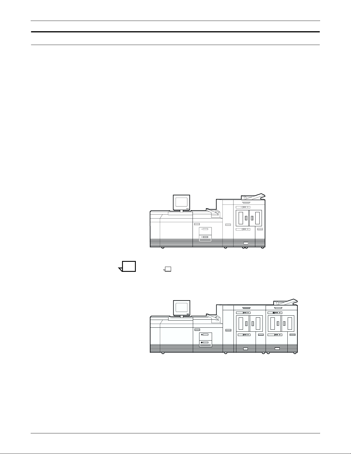
Figure 3-3. 96 printer—Inverter feeder/stacker only
Note: This configuration is available on the 96 and 96 MICR
only.
Figure 3-4. 96/4635/180 printer—Inverter feeder/stacker +
feeder/stacker
3-4 XEROX DOCUPRINT 96/4635/180 IPS INSTALLATION PLANNING GUIDE
Page 35

PRINTER COMPONENTS AND OPTIONS
Figure 3-5. 4635/180 printer—Inverter feeder/stacker + feeder/
stacker + feeder/stacker
Figure 3-6. 4635/180 printer—Inverter feeder/stacker + feeder/
stacker + feeder/stacker + feeder/stacker
Note: The bypass transport is not available on this configuration
(printer and inverter feeder/stacker plus three feeder/stackers). The
input enablement kit is available with this configuration only on the
180 printer.
XEROX DOCUPRINT 96/4635/180 IPS INSTALLATION PLANNING GUIDE 3-5
Page 36

PRINTER COMPONENTS AND OPTIONS
Printer options
Bypass transport
The bypass transport and input enablement options provide an
interface between your DocuPrint system and your finishing and
feeding accessories. However, these feeding and finishing options
require separate AC and DC power sources that are independent of
your printer.
Consult your Xerox sales representative, as well as the sales
representative of the company from which you purchased your
finishing and feeding equipment, for specific electrical and space
requirements.
The ability to add a third-party finisher to your DocuPrint system is
made possible by the bypass transport option. Finishers increase
your production capabilities by providing a wide variety of finishing
choices (for example, slitting, booklet making, binding, and so forth).
Connected to the feeder/stacker, the bypass transport allows
finishers to interface directly with your DocuPrint system. It accepts
all paper stocks within the DocuPrint 96/4635/180 range and
accommodates simplex and duplex printing.
3-6 XEROX DOCUPRINT 96/4635/180 IPS INSTALLATION PLANNING GUIDE
Page 37
Bypass transport printer configurations
The following 96/4635/180 printer configurations may have the
bypass transport:
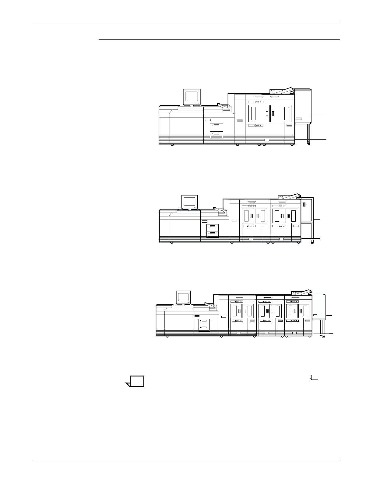
Figure 3-7. 96 printer with inverter feeder/stacker + bypass
transport
1 Bypass transport paper output location
2 Input enablement device paper input location
Figure 3-8. 96/4635/180 with inverter feeder/stacker + feeder/
stacker + bypass transport
PRINTER COMPONENTS AND OPTIONS
1
2
1
1 Bypass transport paper output location
2 Input enablement device paper input location
Figure 3-9. 4635/180 with inverter feeder/stacker + feeder/
stacker + feeder/stacker + bypass transport
1 Bypass transport paper output location
2 Input enablement device paper input location
Note: This configuration is not available for the DP96.
2
1
2
XEROX DOCUPRINT 96/4635/180 IPS INSTALLATION PLANNING GUIDE 3-7
Page 38
PRINTER COMPONENTS AND OPTIONS
Input enablement
Adding a third-party feeder to your DocuPrint system is made
possible by the input enablement option. The DocuPrint 96/4635
printers accept cut sheets from the feeding device through an entry
slot at the lower right side of the last feeder/stacker module.
The input enablement option provides extended paper feed
capability from third-party feeder devices. Sheets are received from
third party feeder devices through an entry slot located in the last
feeder/stacker module of the system.
The DP180 printer accepts cut sheets from the rear of the stacker
into a feeding device that replaces an existing high-capacity feeder
assembly.
Note: The DocuPrint 4635 can support a maximum of three feeder/
stackers with both the input enablement and the bypass transport.
The DocuPrint 96 can support a maximum of two feeder/stackers
with both the input enablement and the bypass transport. The
DocuPrint 180 can support a maximum of three feeder/stackers with
both the input enablement and the bypass transport. For the
DocuPrint 180, a maximum of four feeder/stackers can be supported
with the input enablement device only.
The following figure illustrates the system with the bypass transport
and the input enablement device.
Figure 3-10. Bypass transport module and input enablement
device
1 Bypass transport paper output location
2 Input enablement device paper input location
3-8 XEROX DOCUPRINT 96/4635/180 IPS INSTALLATION PLANNING GUIDE
Page 39

Configurations supported
PRINTER COMPONENTS AND OPTIONS
The input enablement kit and/or bypass transport are supported on
the 96/4635/180 configurations as follows:
96 configurations Input enablement kit and/or
• Inverter feeder/stacker only
• Inverter feeder/stacker + feeder/stacker
4635 configurations Input enablement kit and/or
• Inverter feeder/stacker + feeder/stacker
• Inverter feeder/stacker + feeder/stacker + feeder/stacker
180 configurations Input enablement kit and/or
• Inverter feeder/stacker + feeder/stacker
• Inverter feeder/stacker + feeder/stacker + feeder/stacker
Input enablement kit only (no bypass transport):
Inverter feeder/stacker + feeder/stacker + feeder/stacker + feeder/
stacker.
bypass transport:
bypass transport:
bypass transport:
XEROX DOCUPRINT 96/4635/180 IPS INSTALLATION PLANNING GUIDE 3-9
Page 40

PRINTER COMPONENTS AND OPTIONS
3-10 XEROX DOCUPRINT 96/4635/180 IPS INSTALLATION PLANNING GUIDE
Page 41

4. 4Preparing for installation
This chapter assists you in preparing for the installation of your Xerox
DocuPrint 96/4635/180 IPS and 96/4635/180 MICR IPS.
Preparing for installation is a responsibility shared by personnel at
your site and Xerox. Your service representatives are available to
discuss installation issues and to assist you in completing the site
installation tasks.
Prior to installation, you must select and prepare an appropriate
location for the printer and order supplies. This chapter helps you
accomplish these tasks by providing the following information:
• A summary of your responsibilities and those of your Xerox
service representative
• A checklist of installation planning activities.
• Connectivity requirements for setting up the IPS to receive data
from the IBM host.
For information on controller power and space requirements, refer to
the “Controller specifications and requirements” chapter of this guide.
For facts about printer power and space requirements, refer to the
“Printer specifications and requirements” chapter of this guide.
Responsibilities
Xerox responsibilities
This section describes your site responsibilities and the
responsibilities of your service representatives. Included are some
joint responsibilities.
This section lists the responsibilities of the service representatives
and system analysts prior to, during, and after installation:
• Site selection
— Assist in site selection
— Inspect and approve the site.
• Installation
— Schedule the delivery of the hardware
— Monitor installation activities
— Assist you in ordering any supplies required
— Configure system parameters.
— Assist with the entry of DFA personality profiles for use with
third-party feeding or finishing devices.
XEROX DOCUPRINT 96/4635/180 IPS INSTALLATION PLANNING GUIDE 4-1
Page 42

PREPARING FOR INSTALLATION
— Create default input and output configurations for your
system
— Obtain and enable customer’s operating system software
license text string
— Install the DocuPrint system
— Install optional Sixth Sense hardware and software.
• Training
— Provide initial operator training
— Provide information and assistance in registering for Xerox
Customer Education classes or obtaining tutorials.
• Service
— Review preventive maintenance schedules and service call
procedures
— Provide ongoing maintenance
— Assist in resolving hardware and software problems.
Customer responsibilities
Your responsibilities prior to, during, and after installation of the IPS
are to schedule and monitor your installation activities:
• Site personnel
— Identify the person at your site who will be the primary
interface with Xerox
— Make sure the on-site primary interface is available to the
service representative before and during the installation.
• Site preparation
— Select and prepare the site for the IPS installation
(including proper power, air conditioning, and work space)
— Install Ethernet or Token Ring to system location
— Obtain the necessary interfaces, cables, transceivers,
and so forth
Note: You are responsible for obtaining, stringing, and
maintaining fully-populated bus and tag cables for channelattached systems.
— Plan and schedule installation activities
— Convert any host-resident fonts to 300 dpi (required for 96
MICR and 4635 MICR IPS)
— For channel-attached systems: Provide your host channel
address to your Xerox representative
— Sysgen your host to print to an AFP Type1, Group 3 printer.
Refer to your IBM documentation for further information
— Set the missing interrupt counter (MIH) at the host to 15
minutes
— Provide a list of the stocks you want in your default input
tray configuration
4-2 XEROX DOCUPRINT 96/4635/180 IPS INSTALLATION PLANNING GUIDE
Page 43

PREPARING FOR INSTALLATION
— Review this Installation Planning Guide thoroughly
— Have the required parameters defined for configuring PSF
to print on the IPS. Refer to the “Defining the channel
attached printer to the host” or the “Defining the printer to
the host: TCP/IP attachment” appendix of this guide for
examples and explanations of these parameters.
• Training
— Select the personnel to undergo operator training
— Set up the operator training schedules.
• Applications
— Work with your Xerox or Xerox Ltd. system analyst to
determine requirements for the initial applications
— In a mixed environment, where there is a variety of printing
systems, discuss print quality differences with your service
representative.
XEROX DOCUPRINT 96/4635/180 IPS INSTALLATION PLANNING GUIDE 4-3
Page 44

PREPARING FOR INSTALLATION
Installation planning checklist
To aid you in printer installation planning, the following is a checklist
that lists the tasks that you and your service representative must
complete before installation. If you have questions about any of these
activities, contact your sales or service representative.
Use the time frames in this checklist as guidelines. It is best to consult
your suppliers to determine the required lead times.
Table 4-1.96/4635/180 IPS installation planning checklist
Date
Week Activity Reference Responsibility
-4 Select location for the 96/4635/180 IPS. Chapters 5 and 6 Customer ________
completed
Order additional documentation, if necessary. Call XDSS at 800-
327-9753; see
Appendix B (U.S.)
Register for Xerox Customer Education classes
and order tutorials, if necessary.
Schedule printer delivery. Xerox ________
Convert your IBM host-resident fonts to 300 dpi.
Note: 180 IPS only: If you want to keep your
resources at 240 dpi, you may purchase a
special ROS board which enables the 180 IPS
printer to interpolate 240 dpi resources directly
to 600 dpi without impacting print quality.
Consult your sales representative about this
option.
-3 Schedule hardware delivery. Sales rep. Customer and Xerox ________
Prepare site:
Appendix B Customer and Xerox ________
Chapter 1 and
sales rep.
Chapters 4 to 6 Customer ________
• Provide a table with adequate space for
hardware and cables.
• Ensure proper electrical outlets are
installed.
Customer ________
Customer ________
________
________
________
• Install Token Ring to system location (if
appropriate).
• Install Ethernet to system location (if
appropriate).
________
________
• Ensure proper operating environment.
• Obtain and string bus and tag cables (must
be fully populated), if needed.
BBBBBBB
• Generate the host for an AFP1 device and
IPL, as required
• Provide analog phone line access for
optional Sixth Sense installations.
4-4 XEROX DOCUPRINT 96/4635/180 IPS INSTALLATION PLANNING GUIDE
Page 45

PREPARING FOR INSTALLATION
Table 4-1.96/4635/180 IPS installation planning checklist
(continued)
Date
Week Activity Reference Responsibility
-2 Inspect and approve site. Xerox ________
completed
Order consumable supplies. Minimum supplies
needed for installation are:
Chapter 4,
Appendix A, and
sales rep.
• Paper (2 cartons)
• Developer (1 carton) or
Developer, MICR (1 carton)
• Fuser agent (2 boxes).
• Dry ink (1carton). or
Dry ink, MICR (1 carton).
Note: After installation, you will need to
establish a procedure for ordering supplies
according to your ongoing production
requirements.
-1 Schedule operator training. Systems analyst
Define parameters needed to configure PSF for
connectivity to the IPS printer.
Install Make sure supplies are available. Chapter 4 and
5R161
5R573
8R2955
6R206
6R819
(U.S.) or site
representative
(non-U.S.)
Appendix D and E Customer ________
Appendix A
Customer and Xerox ________
Customer and Xerox ________
Customer ________
Make sure system administrators are available
during software installation.
Provide host channel address and channel unit
address (if printing via channel).
Provide host IP address. Appendix D and E Customer ________
Sysgen your host to print to an AFP Type 1,
Group 3 printer.
Set up Data Transfer Mode. Customer and Xerox ________
Install 96/4635/180 IPS printer hardware and
software.
Have operators available for training. Appendix B Customer ________
Check documentation and software kits for
completeness.
Have test jobs ready to run. Customer ________
Provide stocks needed for default input
configuration
Provide parameters needed to configure PSF
for connectivity to the IPS printer.
Appendix D or E Customer ________
Customer ________
Customer ________
Customer and Xerox ________
Xerox ________
Customer ________
Customer ________
XEROX DOCUPRINT 96/4635/180 IPS INSTALLATION PLANNING GUIDE 4-5
Page 46

PREPARING FOR INSTALLATION
Table 4-1.96/4635/180 IPS installation planning checklist
(continued)
Week Activity Reference Responsibility
Obtain and enable customer software license. Chapter 7 Xerox ________
Date
completed
Postinstall
Become familiar with support services. Appendix B Customer ________
Establish supplies maintenance procedure. Appendix A Customer ________
Provide ongoing 96/4635/180 IPS maintenance. Guide to
Customer and Xerox ________
Performing
Routine
Maintenance
Order additional documentation, as necessary. Appendix B Customer ________
Adjust the IOT alignment and magnification. Xerox ________
4-6 XEROX DOCUPRINT 96/4635/180 IPS INSTALLATION PLANNING GUIDE
Page 47

Connectivity requirements
Ethernet specifications
PREPARING FOR INSTALLATION
A Token Ring network or an Ethernet local area network running
TCP/IP is the network communication system that may be used to
transport documents from the host to the IPS. This is an alternative
to the channel-attached configuration, in which data is transmitted via
bus and tag cables and the HCU.
Note: The TCP/IP connectivity option is not available in a VM or
VSE environment. However, a printing system with PSF/2 or
PSF/6000 can attach to a PSF/VSE system and the PSF/2 or PSF/
6000 can furnish the TCP/IP support for the IPS printer.
The Ethernet connection to the printer controller processor must be
compatible with the Institute of Electrical and Electronics Engineers
(IEEE) 802.3 standard.
The Ethernet interface on the processor is a 10 Mb/sec twisted pair
standard (10BaseT and 100BaseT). The MII (for UltraSPARC) Coax
Ethernet is enabled with an adapter cable.
Token Ring specifications
Channel-attached specifications
Note: Only the RS/6000 currently supports 100 Mb Ethernet
connectivity.
Work with your system administrator to assess what type of network
you have and what modifications need to be made to supply an
Ethernet connector to the printer controller processor.
The Token Ring connection must be compatible with the IEEE 802.3
standard. The printer controller processor has a 4MB or 16 MB
Token Ring Auto interface (16 MB is preferred).
For an online configuration with an IBM host system, the following
cables must be available:
• Bus and tag cables (bus in, bus out, tag in, tag out)
• Terminators (if necessary, due to location on channel).
For your convenience, it is possible to order the Bus and Tag cables
for the printer through Xerox Corporation on a purchase-only basis.
Contact your Xerox or Xerox Ltd. sales representative for current
pricing and order information.
XEROX DOCUPRINT 96/4635/180 IPS INSTALLATION PLANNING GUIDE 4-7
Page 48

PREPARING FOR INSTALLATION
4-8 XEROX DOCUPRINT 96/4635/180 IPS INSTALLATION PLANNING GUIDE
Page 49
Power requirements
5. 5Controller specifications and
requirements
This chapter provides power and space requirements for your
96/4635/180 IPS printer controller. It also provides controller
environmental specifications.
For facts about printer power and space requirements, refer to the
“Printer specifications and requirements” chapter of this guide.
Your 96/4635/180 IPS controller has important power requirements
that must be accommodated. These requirements are summarized in
the table below.
For details on printer power requirements, refer to the “Printer
specifications and requirements” chapter of this guide.
Table 5-1. 96/4635/180 IPS controller
60 Hz electrical requirements
Amp
Voltage
Sun Ultra 2 printer controller 100 to 240 VAC 15 amp 0.4 KVA 5-15R
HCU 100 to 240 VAC 15 amp 0.4 KVA 5-15R
Sun Ultra 60 printer controller 100 to 240 VAC 15 amp. 0.4 KVA 5-15R
Table 5-2. 96/4635/180 IPS controller
50 Hz electrical requirements
Voltage
Sun Ultra 2 printer controller 100 to 240 VAC 15 amp 0.4 KVA
HCU 100 to 240 VAC 15 amp 0.4 KVA
Sun Ultra 60 printer controller 100 to 240 VAC 15 amp 0.4 KVA
service KVA rating NEMA
Amp.
service KVA rating
Agency certification: UL 478 and 1950, IEC 950, CE Mark,
CSA 22.2 #220-1986, FCC (Class A), and VDE 0871 (Class A).
If the optional Sixth Sense feature is configured, you must provide a
100 to 240 VAC outlet for modem power connection.
XEROX DOCUPRINT 96/4635/180 IPS INSTALLATION PLANNING GUIDE 5-1
Page 50

CONTROLLER SPECIFICATIONS AND REQUIREMENTS
Outlet configurations
This section discusses specifications for system outlets and the
required wall outlet configurations for the USA / Canada and
internationally.
Note: All power outlets must be dedicated to this equipment. When
determining the electrical connections for your printing system, make
sure that:
• Each power cord has a separate circuit.
• The printer power cord configurations match your receptacle.
• Your electrical outlets are within the required specifications.
50 Hz systems: Ensure that power connections are per local codes/
regulations.
The following figure shows a 60 Hz American and Canadian wall
outlet in which to plug the printer controller and HCU.
Figure 5-1. 60 Hz wall outlet
12
3
1 AC Hot (ACH)
2 AC Hot (ACH)
3 Earth Ground (GND)
The required American and Canadian wall outlet voltage is 100 to
120 VAC between AC hot and neutral, and between AC hot and GND.
The voltage is less than three VAC between GND and neutral.
Refer to the 60 Hz and 50 Hz controller electrical requirements tables
earlier in this chapter for a description of the power specifications for
the controller.
Warning: To reduce the risk of electrical shock, do not plug
!
components into any other type of power system. Contract your
facilities manager or a qualified electrician if you are not sure what
type of power is supplied to your work area.
5-2 XEROX DOCUPRINT 96/4635/180 IPS INSTALLATION PLANNING GUIDE
Page 51
Space requirements
Printer controller placement
CONTROLLER SPECIFICATIONS AND REQUIREMENTS
The printer controller consists of the Sun workstation and, for
channel-attached systems, the HCU. This section provides
recommendations for placement of controller hardware components.
For printer component space requirements, refer to the “Printer
specifications and requirements” chapter of this guide. Contact your
service representative if you have questions not specifically
addressed in this guide.
You should consider the following factors when deciding where to
place the DocuPrint printer controller:
• Adequate work space and service clearance around the
equipment
• Proximity to electrical and network connectors
• Security of the work area. You may need to place the system in
an area where you can restrict access to it.
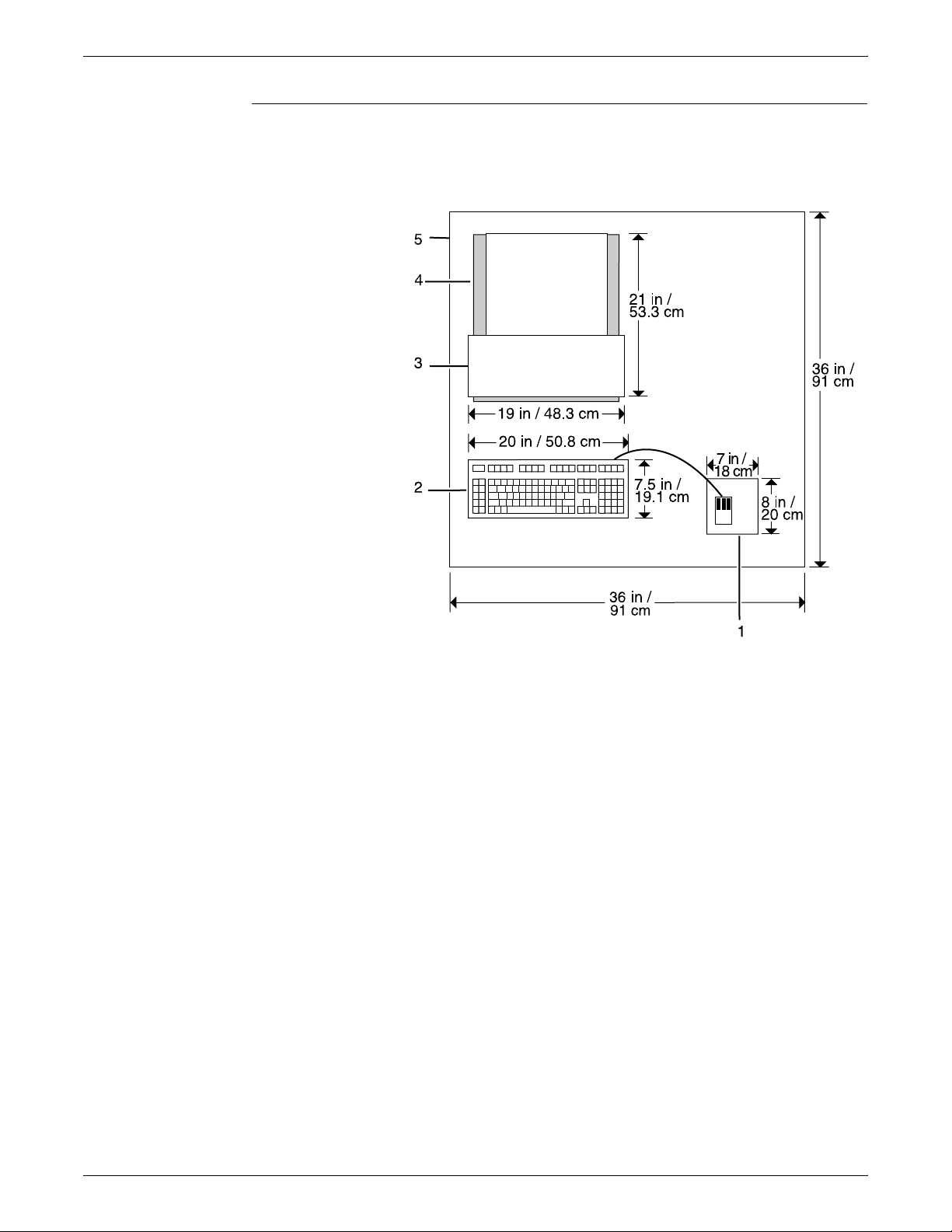
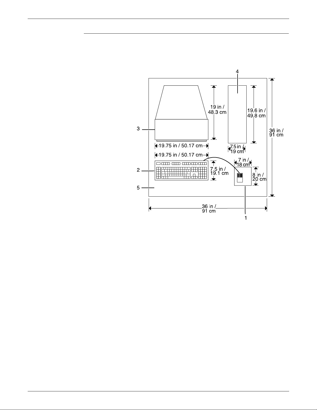
You must supply a table or desk as a work surface for both the printer
controller and the HCU. The top of the table must provide at least 36
by 36 inches / 91.4 by 91.4 cm of space for each component, to allow
enough space for the components and cables, as well as for service
access.
Refer to the “Printer controller specifications and requirements”
summary table at the end of this chapter to make sure the tables you
supply can support the weight of the printer controller hardware
elements and of the HCU, and that they are suitable for the intended
use.
Warning: The printer controller must be positioned within the line-
!
of-sight of the printer for safety purposes while servicing the
equipment.
Caution: Position the table at least 6 inches / 15.2 cm from the wall.
Make sure the workstation processor and the HCU are at least
12 inches / 30.4 cm from the wall. Do not put the processor or the
HCU on the IPSLPS printer.
!
XEROX DOCUPRINT 96/4635/180 IPS INSTALLATION PLANNING GUIDE 5-3
Page 52
CONTROLLER SPECIFICATIONS AND REQUIREMENTS
Sun Ultra 2 workstation placement
Following are guidelines for placement of the Sun Ultra 2 workstation
components of the printer controller.
Figure 5-2. Sun Ultra 2 printer controller hardware
1 Mouse and mouse pad
2 Keyboard
3 Monitor
4 Processor
5 Table
5-4 XEROX DOCUPRINT 96/4635/180 IPS INSTALLATION PLANNING GUIDE
Page 53

CONTROLLER SPECIFICATIONS AND REQUIREMENTS
Processor clearance When you place your workstation processor on a table top, make
sure to allow at least 6 inches / 15.2 cm of unobstructed space at the
rear and both sides of the processor. Do not allow any piece of
equipment to blow warm air into the air-intake vents of the processor.
The following illustration shows fan and vent locations on the Ultra 2
processor.
Figure 5-3. Sun Ultra 2 fan and vent locations to keep clear
1
2
3
1 Vent
2 Fan
3 Vent
Caution: Do not place a monitor with a base larger than the
processor on top of the unit. Do not block any fan or vents on the
sides or rear of the processor.
XEROX DOCUPRINT 96/4635/180 IPS INSTALLATION PLANNING GUIDE 5-5
Page 54
CONTROLLER SPECIFICATIONS AND REQUIREMENTS
Sun Ultra 60 workstation placement
Following are guidelines for placement of the Sun Ultra 60
workstation components of the printer controller.
Figure 5-4. Sun Ultra 60 printer controller hardware
1 Mouse and mouse pad
2 Keyboard
3 Monitor
4 Processor
5 Table
To ensure consistent performance and avoid any damage to
equipment, follow these rules for placing the components of the Sun
Ultra 60 controller.
Do:
• Place the monitor and processor on a desk or table top,
separate from the printer. The monitor should be placed beside
the processor, on the same surface. (The cartridge tape drive
may be placed on top of the processor.)
• Keep the processor in an upright, vertical position as illustrated
below.
• Allow at least 6 inches / 152 mm of unobstructed space at the
front and rear of the processor, so the fan and vents are not
blocked.
5-6 XEROX DOCUPRINT 96/4635/180 IPS INSTALLATION PLANNING GUIDE
Page 55

CONTROLLER SPECIFICATIONS AND REQUIREMENTS
The following illustration shows fan and vent locations on the
front and back of the controller.
Figure 5-5. Sun Ultra 60 fan and vent locations to keep clear
1 Vent in front of processor
2 Fan in back of processor
3 Vent in back of processor
Do not:
• Do not place the controller monitor on top of the processor.
• Do not allow any piece of equipment to blow warm air into the
air intake vents of the processor.
• Do not place the processor on its side, or in any other position
but the upright, vertical position shown in the previous figure.
• Do not place the processor or monitor on top of the printer.
XEROX DOCUPRINT 96/4635/180 IPS INSTALLATION PLANNING GUIDE 5-7
Page 56
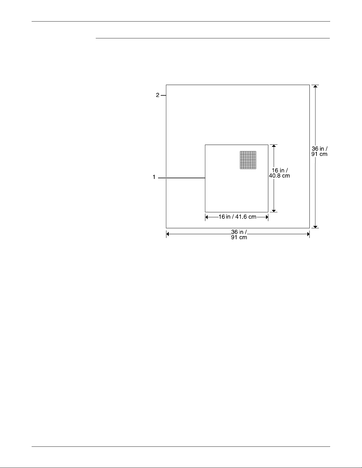
CONTROLLER SPECIFICATIONS AND REQUIREMENTS
HCU placement (channel-attached systems only)
The following shows the recommended HCU hardware placement,
for channel-attached systems.
Figure 5-6. HCU hardware (for channel-attached systems)
1 HCU
2 Table
Do not:
• Do not place the controller monitor on top of the processor.
• Do not allow any piece of equipment to blow warm air into the
air intake vents of the processor.
• Do not place the processor on its side, or in any other position
but the upright, vertical position shown in the previous figure.
• Do not place the processor or monitor on top of the printer.
5-8 XEROX DOCUPRINT 96/4635/180 IPS INSTALLATION PLANNING GUIDE
Page 57
CONTROLLER SPECIFICATIONS AND REQUIREMENTS
Printer controller hardware specifications and requirements summary
The following table summarizes the specifications and electrical
requirements of your DocuPrint IPS printer controller hardware
components.
For a summary of printer hardware specifications and requirements,
refer to the “Printer specifications and requirements” chapter of this
guide. Contact your service representative if you have questions not
specifically addressed in this guide.
Table 5-3.96/4635/180 IPS printer controller specifications and
power requirements
Dimensions (depth,
Device
Host Channel
Unit (HCU)
(channelattached
systems only)
Processor d=16.1 in. / 40.9 cm
width, height) Weight
d=15 in. / 40.8 cm
h=5 in. / 12.6 cm
w= 16 in. / 41.6 cm
w=16.4 in. / 41.7 cm
h= 3 in. / 7.6 cm
26 lbs. 10
oz. / 12.4
kgs
27 lbs. /
12.7 kgs
Heat
dissipation Power requirements Cable lengths
N/A 120 VAC within 6 feet;
120 volt at 2 amps or
240 volt at 1 amp
1,100 Btu
per hours
Sun Ultra 2 (60 Hz):
100 to 240 VAC,
15 amp, 0.4 KVA,
5-15R NEMA
Sun Ultra 2 (50 Hz):
100 to 240 VAC,
15 amp, 0.4 KVA
Sun Ultra 60 (60 Hz):
100 to 240 VAC,
15 amp, 0.4 KVA,
5-15R NEMA
Bus and tag
cables must
conform to host
system
requirements
(200 to 400 ft. /
66.7 to 133.3 m)
and
accommodate
system setup.
Power: 8 ft. /
2.1 m
Interface to
printer:
20 ft. / 6.1 m
usable length
Sun Ultra 60 (50 Hz):
100 to 240 VAC,
15 amp, 0.4 KVA
Monitor d=6.1 in. / 41cm
w=18.1 in. / 46 cm
h=17.7 in. / 45 cm
4 mm cartridge
tape drive
XEROX DOCUPRINT 96/4635/180 IPS INSTALLATION PLANNING GUIDE 5-9
d=12.2 in. / 31 cm
w=7.5 in. / 19 cm
h=2.8 in. / 7 cm
61 lbs. /
27.7 kg
8 lbs. /
6.6 kg
408 Btu
per hour
--- 100-120/200-240 VAC,
100-120 ~ VAC,
1 phase, 50-60 Hz,
3.0 amp, 0.4 KVA
200-240 ~ VAC,
1 phase, 50-60 Hz,
2.0 amp, 0.4 KVA
0.8/0.4 amp, 47-63 Hz
Video cable to
processor:
46 in. / 1.17 m
Power: 8 ft. /
2.4 m
SCSI cable to
processor or
additional SCSI
device:
28 in. / 71 cm
Page 58

CONTROLLER SPECIFICATIONS AND REQUIREMENTS
Table 5-3.96/4635/180 IPS printer controller specifications and
power requirements (continued)
Dimensions (depth,
Device
width, height) Weight
Keyboard d=7.5 in. / 17.8 cm
w=18 in. / 45.7 cm
Mouse d=3 in. / 8 cm
w=4 in. / 10 cm
h=2 in. / 5 cm
Heat
dissipation Power requirements Cable lengths
2 lbs. / 1kg --- --- 72 in. / 1.8 m
0.3 lbs. /
--- --- 25 in. / 63 cm
0.14 kg
5-10 XEROX DOCUPRINT 96/4635/180 IPS INSTALLATION PLANNING GUIDE
Page 59

Power requirements
6. 6Printer specifications and
requirements
This chapter provides power and space requirements for your
96/4635/180 printer. It also provides printer environmental
specifications.
For facts about controller power and space requirements, refer to the
“Controller specifications and requirements” chapter of this guide.
Your 96/4635/180 printer has important power requirements that
must be accommodated. These requirements are summarized in the
table below. For further details on power requirements, refer to the
voltage charts and wiring diagrams that follow.
Printer — 60 Hz
(U. S. and Canada)
Printer— 50 Hz
DELTA
WYE
(Star)
For details on controller power requirements, refer to the “Controller
specifications and requirements” chapter of this guide.
Table 6-1.Printer electrical requirements
Amp.
Printer Voltage
180
(Dual
cords)
96/4635 120/240 VAC or 120/208 VAC 50 amp Operating: 7.3
180
4635
96
180
4635
96
120/240 VAC or 120/208 VAC
(Cord 1)
120/240 VAC or 120/208 VAC
(Cord 2)
220, 230, 240 VAC
(3 phase, 4 wire)
380, 400, 415 VAC
(3 phase, 5 wire)
Agency certification: UL 478 and 1950, IEC 950, CE Mark,
CSA 22.2 #220-1986, FCC (Class A), and VDE 0871 (Class A).
service KVA rating NEMA
50 amp
(Cord 1)
30 amp
(Cord 2)
30 amp Consult local
20 amp Consult local
Operating: 7.3
+ .75 per middle
module stacker
+ .75 per middle
module stacker
service rep.
service rep.
14-50R
(Cord 1)
14-30R
(Cord 2)
14-50R
XEROX DOCUPRINT 96/4635/180 IPS INSTALLATION PLANNING GUIDE 6-1
Page 60

PRINTER SPECIFICATIONS AND REQUIREMENTS
Outlet configurations
Printer outlet voltages—60 Hz
This section discusses specifications for system outlets and the
required wall outlet configurations for the USA / Canada and
internationally.
Note: All power outlets must be dedicated to this equipment. When
determining the electrical connections for your printer, make sure
that:
• Each power cord has a separate circuit
• The printer power cord configurations match your receptacle
• Your electrical outlets are within the required specifications.
50 Hz systems: Ensure that power connections are per local codes/
regulations.
The following table shows the voltages for the outlets on your printing
system. All power outlets must have a dedicated circuit for each
system equipment piece. Make sure each power cord has a separate
circuit.
Table 6-2.Printer (60 Hz) voltage requirements at power outlet
Service outlet
configuration Measurement of wiring Nominal Range
4 Wire Line 1 to neutral 120 V RMS 107-127 V RMS
4 Wire Line 2 to neutral 120 V RMS 107-127 V RMS
4 Wire Neutral to ground 0 0-10 V RMS
4 Wire Line 1 to line 2 208 V RMS 182-220 V RMS
4 Wire Line 1 to line 2 240 V RMS 210-254 V RMS
6-2 XEROX DOCUPRINT 96/4635/180 IPS INSTALLATION PLANNING GUIDE
Page 61

PRINTER SPECIFICATIONS AND REQUIREMENTS
Printer power outlet/cord voltage
configurations—60 Hz
The following figures shows the 60 Hz power outlet configuration for
50 amp NEMA 14-50R (96, 4635, and 180) and 30 amp NEMA 1430R (180 only). Voltage to ground is shown for troubleshooting
purposes.
Figure 6-1. 60 Hz power configuration—50 amp (96/4635/180)
NEMA
14-5 0R
Figure 6-2. 60 Hz power configuration - 30 amp (180 only)
NEMA
14-30R
XEROX DOCUPRINT 96/4635/180 IPS INSTALLATION PLANNING GUIDE 6-3
Page 62

PRINTER SPECIFICATIONS AND REQUIREMENTS
Printer outlet voltages—50 Hz
DELTA configurations—50 Hz For 50 Hz DELTA configurations, measure the DELTA connection
Service outlet
configuration Measurement Nominal Range
4 Wire 220 V Line 1 to line 2 220 V RMS 198-242 V RMS
4 Wire 220 V Line 2 to line 3 220 V RMS 198-242 V RMS
4 Wire 220 V Line 1 to line 3 220 V RMS 198-242 V RMS
4 Wire 230 V Line 1 to line 2 230 V RMS 207-253 V RMS
4 Wire 230 V Line 2 to line 3 230 V RMS 207-253 V RMS
All power outlets must have a dedicated circuit for each system
equipment piece. Make sure each power cord has a separate circuit.
Note: Consult with your service representative to determine the
type of plug and receptacle to be used for your 50 Hz system.
voltages at the power source.
Table 6-3.Printer (50 Hz) DELTA voltage
4 Wire 230 V Line 1 to line 3 230 V RMS 207-253 V RMS
5 Wire 240 V Line 1 to line 2 240 V RMS 216-264 V RMS
5 Wire 240 V Line 2 to line 3 240 V RMS 216-264 V RMS
5 Wire 240 V Line 1 to line 3 240 V RMS 216-264 V RMS
WYE (or Star) configurations—50 Hz For the 50 Hz WYE configuration, measure the WYE or Star
connection voltages at the power source.
Table 6-4.Printer (50 Hz) WYE (Star) 415 voltage
Service outlet
configuration Measurement Nominal Range
5 Wire 415 V Line 1 to line 2 415 V RMS 374-457 V RMS
5 Wire 415 V Line 2 to line 3 415 V RMS 374-457 V RMS
5 Wire 415 V Line 1 to line 3 415 V RMS 374-457 V RMS
5 Wire 415 V Line 1 to neutral 240 V RMS 216-264 V RMS
5 Wire 415 V Line 2 to neutral 240 V RMS 216-264 V RMS
5 Wire 415 V Line 3 to neutral 240 V RMS 216-264 V RMS
6-4 XEROX DOCUPRINT 96/4635/180 IPS INSTALLATION PLANNING GUIDE
Page 63

PRINTER SPECIFICATIONS AND REQUIREMENTS
The following lists the 50 Hz WYE/Star printer outlet information for
380 and 400 volts.
Table 6-5.Printer (50 Hz) WYE (Star) 380 and 400 voltage
Service outlet
configuration Measurement Nominal Range
5 Wire 380 V Line 1 to line 2 380 V RMS 342-419 V RMS
5 Wire 380 V Line 2 to line 3 380 V RMS 342-419 V RMS
5 Wire 380 V Line 1 to line 3 380 V RMS 342-419 V RMS
5 Wire 380 V Line 1 to neutral 220 V RMS 198-242 V RMS
5 Wire 380 V Line 2 to neutral 220 V RMS 198-242 V RMS
5 Wire 380 V Line 3 to neutral 220 V RMS 198-242 V RMS
5 Wire 400 V Line 1 to line 2 400 V RMS 358-438 V RMS
5 Wire 400 V Line 2 to line 3 400 V RMS 358-438 V RMS
5 Wire 400 V Line 1 to line 3 400 V RMS 358-438 V RMS
5 Wire 400 V Line 1 to neutral 230 V RMS 207-253 V RMS
5 Wire 400 V Line 2 to neutral 230 V RMS 207-253 V RMS
5 Wire 400 V Line 3 to neutral 230 V RMS 207-253 V RMS
Printer power outlet/cord voltage
configurations—50 Hz
For 50 Hz systems outlet/power cord configurations, consult your
local service representative to determine the type of plug and
receptacle to use.
XEROX DOCUPRINT 96/4635/180 IPS INSTALLATION PLANNING GUIDE 6-5
Page 64
PRINTER SPECIFICATIONS AND REQUIREMENTS
Environmental specifications
When you select a site location for your DocuPrint printer, avoid
environments with extreme variations in temperature and other
hazards, such as excessive dust or humidity. Recommended
environmental ranges for the work area are as follows:
Table 6-6. Environmental specifications for 96/4635/180
printers
Condition Range
Operating
temperature:
Humidity: Recommended:
Altitude: Normal:
Heat dissipation:
96 and 4635
(2-stacker system)
(2-stacker system)
Audible noise: Operating:
Recommended:
Energy Saver:
180
Energy Saver:
Maximum:
Maximum:
Maximum:
Operating:
Operating:
Continuous:
Minimum:
Minimum:
Standby:
Standby:
Impulse:
68° F to 76° F /
20° C to 24° C
50° F / 10° C
85° F / 29° C
45% ±10%
30%
65%
Up to 6,000 feet / 1,830 m
above sea level
9,000 feet / 2,743 m above
sea level.
28,140 BTU/hour
4,454 BTU/hour
2,700 BTU/hour
32,770 BTU/hour
4,454 BTU/hour
2,700 BTU/hour
82 dB(A)
82 dB(A)
Standby:
Continuous:
Impulse:
6-6 XEROX DOCUPRINT 96/4635/180 IPS INSTALLATION PLANNING GUIDE
52 dB(A)
N/A
Page 65

Space requirements
PRINTER SPECIFICATIONS AND REQUIREMENTS
You should consider the following factors when deciding where to
place the printing system hardware components:
• Adequate work space and service clearance around the
equipment
• Proximity to electrical and network connectors
• Security of the work area. You may need to place the system in
an area where you can restrict access to it. This may be
important if your personnel need to print confidential documents
or if you are concerned with unauthorized usage.
Dimensions and weights of the printer components are listed in this
section, along with diagrams, to help you visualize the sizes and total
space requirements.
Note: There must be a 78-inch / 198-cm vertical clearance
throughout the entire area. Your printer must be installed in a fixed
location with a minimum clearance space of 36 inches / 91.4 cm
around all sides of each piece of equipment for access by service
personnel. In addition, there must be 50 inches / 126.9 cm clearance
space in front of the printer.
Printer placement
For information on clearance space and other space planning
considerations, refer to the “Space planning guidelines” section of
this chapter. Contact your service representative if you have
questions not specifically addressed in this guide.
The following configurations are available for the Xerox 96/4635/180
printers:
• Printer + inverter feeder/stacker (96 only)
• Printer + inverter feeder/stacker + feeder/stacker
• Printer + inverter feeder/stacker + feeder/stacker + feeder/
stacker (4635 and 180 only)
• Printer + inverter feeder/stacker + feeder/stacker + feeder/
stacker + feeder/stacker (4635 and 180 only).
Measurements and a top-view diagram for each of these
configurations is provided on the following pages.
XEROX DOCUPRINT 96/4635/180 IPS INSTALLATION PLANNING GUIDE 6-7
Page 66
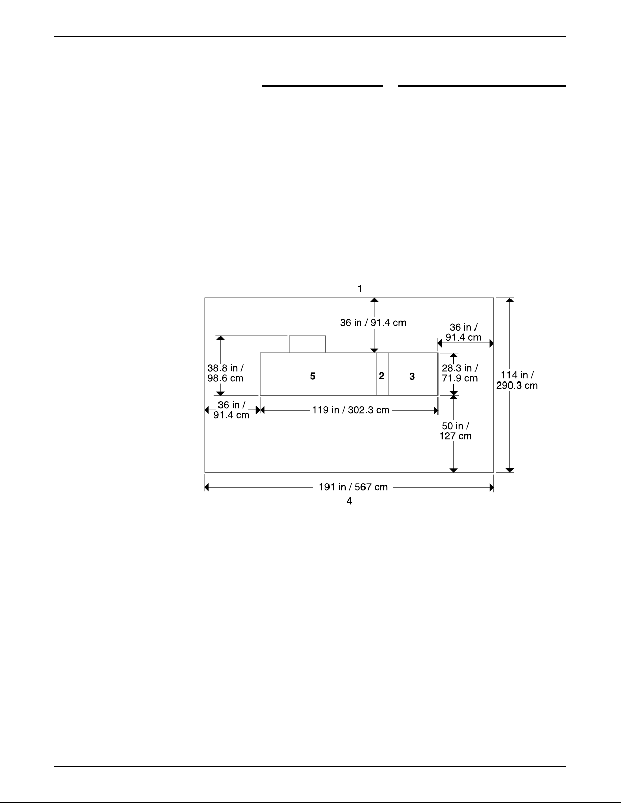
PRINTER SPECIFICATIONS AND REQUIREMENTS
96 printer with inverter feeder/stacker
only
The dimensions of the printer with the inverter feeder/stacker-only
configuration are as follows:
Dimension Specifications
Width: 119 inches / 302.3 cm
Depth: 38.8 inches / 98.6 cm
Height: 59.6 inches / 151.3 cm
Total weight: 1404 pounds / 6370 kg
Total space requirement: 191 by 114 inches /
567 by 290.3 cm
The following illustrates a top view of the space requirements for the
printer with an inverter feeder/stacker-only configuration.
Figure 6-3. 96 with inverter feeder/stacker configuration
1 Back of system
2 Inverter
3 Feeder/stacker
4 Front of system
5 Printer
6-8 XEROX DOCUPRINT 96/4635/180 IPS INSTALLATION PLANNING GUIDE
Page 67

PRINTER SPECIFICATIONS AND REQUIREMENTS
96/4635/180 printer with inverter feeder/
stacker and one feeder/stacker
The dimensions of the printer with the inverter feeder/stacker and
feeder/stacker are as follows:
Dimension Specifications
Width: 151.25 inches / 384.2 cm
Depth: 38.8 inches / 98.6 cm
Height: 59.6 inches / 151.3 cm
Total weight: 2,588 pounds / 1174.9 kg
Total space requirement: 223.25 by 114 inches /
567 by 290.3 cm
The following illustrates a top view of the space requirements for the
printer with an inverter feeder/stacker and one feeder/stacker.
Figure 6-4. 96/4635/180 with inverter feeder/stacker + feeder/
stacker configuration
1 Back of system
2 Inverter
3 Feeder/stacker
4 Feeder/stacker
5 Front of system
6 Printer
XEROX DOCUPRINT 96/4635/180 IPS INSTALLATION PLANNING GUIDE 6-9
Page 68
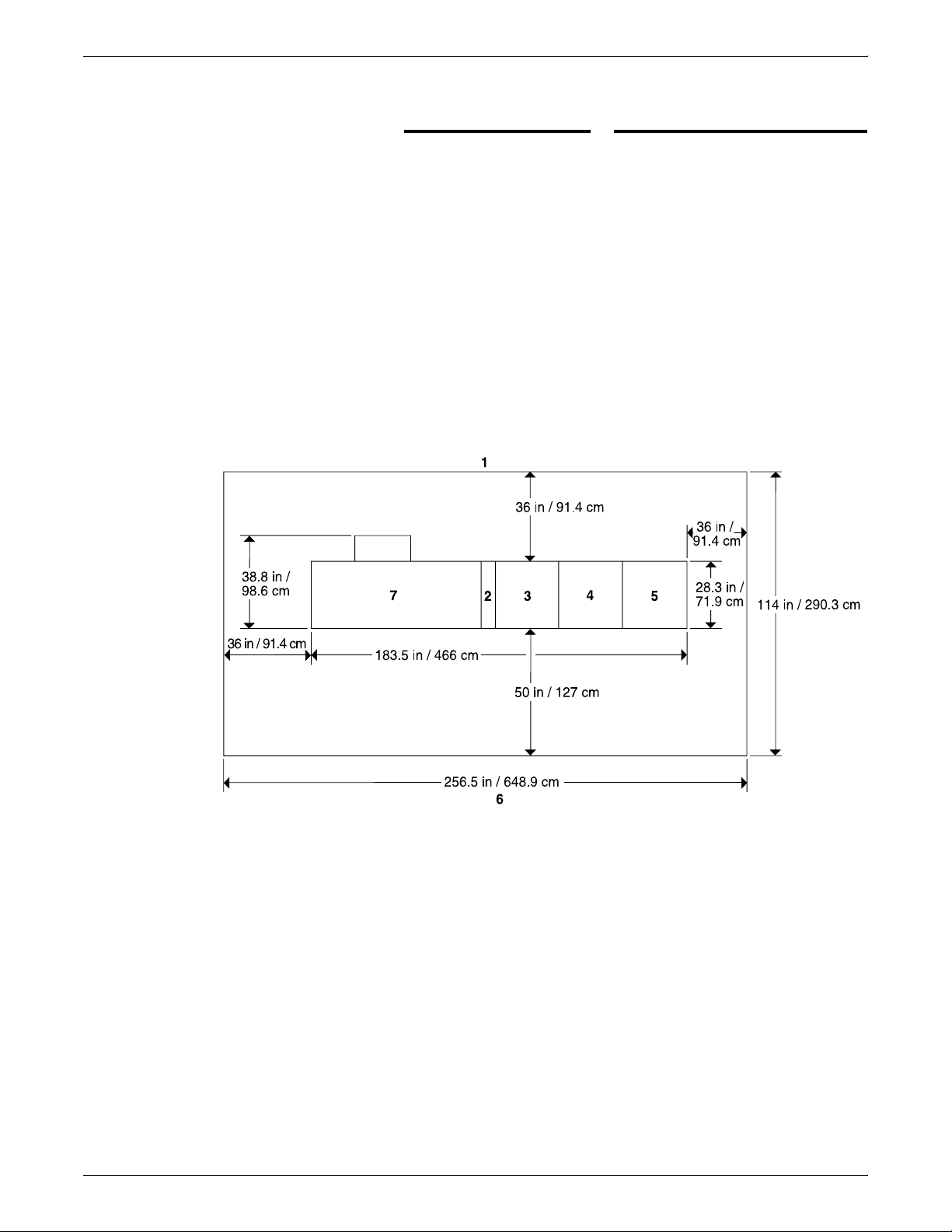
PRINTER SPECIFICATIONS AND REQUIREMENTS
4635/180 printer with inverter feeder/
stacker and two feeder/stackers
The dimensions of the printer with the inverter feeder/stacker, and
two feeder/stackers are as follows:
Dimension Specifications
Width: 183.50 inches / 466.1 cm
Depth: 38.8 inches / 98.6 cm
Height: 59.6 inches / 151.3 cm
Total weight: 3,109 pounds / 1,411.9 kg
Total space requirement: 256.5 by 114 inches /
648.9 by 290.3 cm
The following illustrates a top view of the space requirements for the
printer with an inverter feeder/stacker and two feeder/stackers.
Figure 6-5. 4635/180 printer with inverter feeder/stacker +
feeder/stacker + feeder/stacker
1 Back of system
2 Inverter
3 Feeder/stacker
4 Feeder/stacker
5 Feeder/stacker
6 Front of system
7 Printer
6-10 XEROX DOCUPRINT 96/4635/180 IPS INSTALLATION PLANNING GUIDE
Page 69
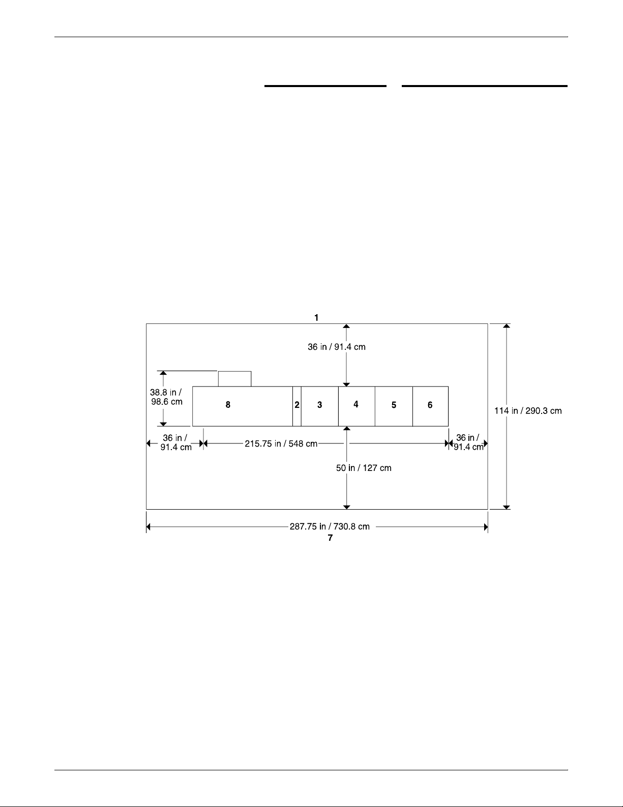
PRINTER SPECIFICATIONS AND REQUIREMENTS
4635/180 printer with inverter feeder/
stacker and three feeder/stackers
The dimensions of the printer with the inverter feeder/stacker and
three feeder/stackers are as follows:
Dimension Specifications
Width: 215.75 inches / 548 cm
Depth: 38.8 inches / 98.6 cm
Height: 59.6 inches / 151.3 cm
Total weight: 3,630 pounds / 1,648.9 kg
Total space requirement: 287.75 by 114 inches /
730.8 by 290.3 mm
The following illustrates a top view of the space requirements for the
printer with a dual feeder and stitcher/stacker configuration.
Figure 6-6. 4635/180 printer with inverter feeder/stacker +
feeder/stacker + feeder/stacker + feeder/stacker
configuration
1 Back of system
2 Inverter
3 Feeder/stacker
4 Feeder/stacker
5 Feeder/stacker
6 Feeder/stacker
7 Front of system
8 Printer
XEROX DOCUPRINT 96/4635/180 IPS INSTALLATION PLANNING GUIDE 6-11
Page 70

PRINTER SPECIFICATIONS AND REQUIREMENTS
Bypass transport specifications
The bypass transport option enables you to add a third-party finishing
device to your 96, 4635, or 180 printer. The bypass transport is
installed by your service representative and remains permanently in
place. You should not attempt to remove or reinstall it. The following
is supported by the bypass transport:
• Paper size and weight — You can use all of the paper sizes
• Sheet exit orientation — 1 to N (the same order in which
• Maximum throughput speed — The bypass transport for the
• Sheet exit height — 34 inches / 86 cm above the floor.
and weights supported on the 96/4635/180 in the bypass
transport.
sheets are fed from the printer), delivered face down.
96 and 135 printer supports throughput speeds of up to 139
ppm (pages per minute). The 180 bypass transport supports
speeds up to 180 ppm. (These rates are based on stocks up to
9 by 14.33 / 229 by 364 mm in length.)
6-12 XEROX DOCUPRINT 96/4635/180 IPS INSTALLATION PLANNING GUIDE
Page 71
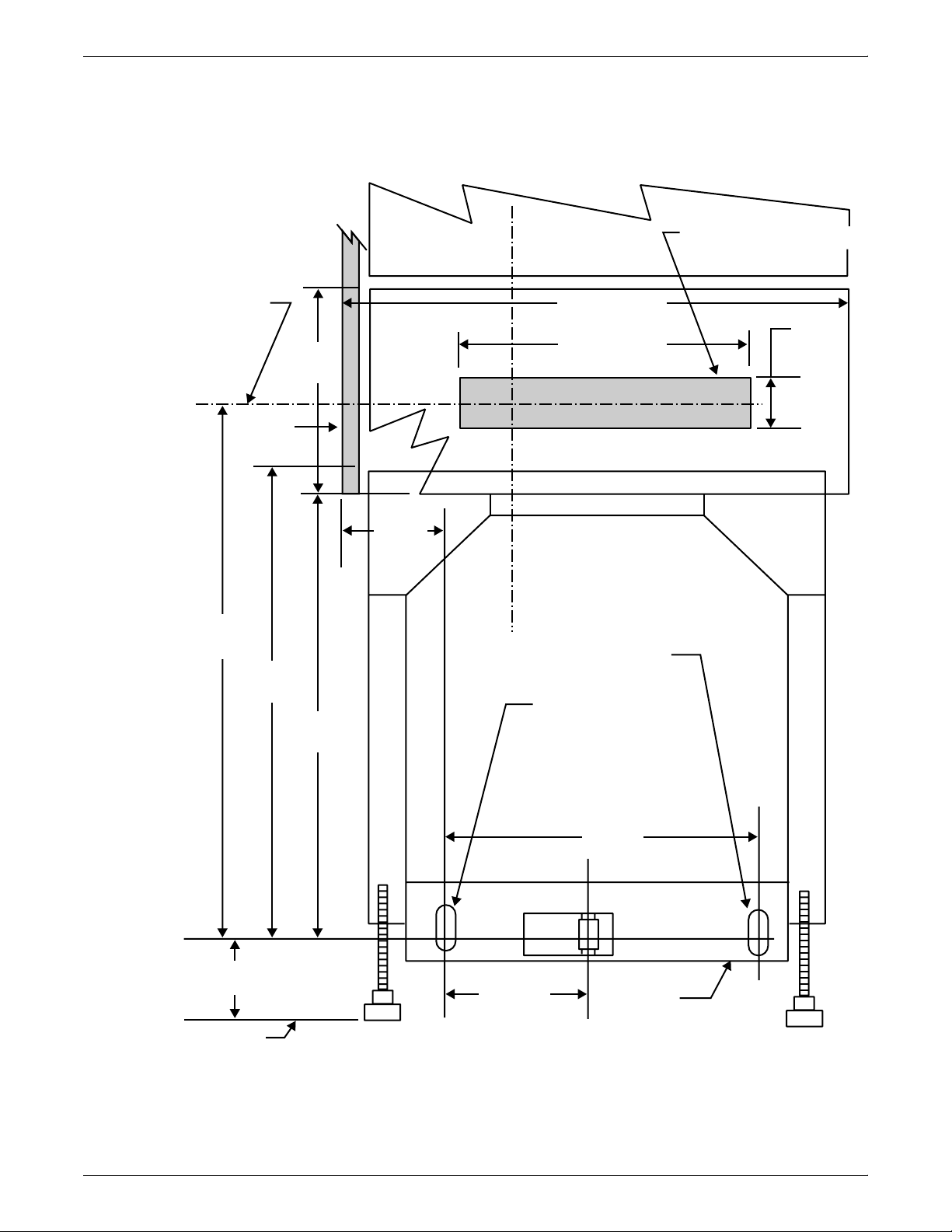
PRINTER SPECIFICATIONS AND REQUIREMENTS
Dimensions The following figure shows the dimensions of the bypass transport in
millimeters and inches from the right end view.
Figure 6-7. Bypass transport dimensions
Sheet
path
31.6 in /
804 mm
13 in /
334.6 mm
Front
cover
27 in /
686 mm
645.5 mm
26 in /
4 in /
102 mm
17 in /
440 mm
Registration edge
28 in / 719 mm
16 in / 406 mm
0.6 x 1.3 in /
15 x 33 mm
0.5 x 1.3 in /
13.3 x 33 mm
Exit
guide
0.8 in /
20 mm
17 in /
440 mm
2.2 in /
56 mm
6.2 in /
157.7 mm
Docking
bracket
Floor
XEROX DOCUPRINT 96/4635/180 IPS INSTALLATION PLANNING GUIDE 6-13
Page 72
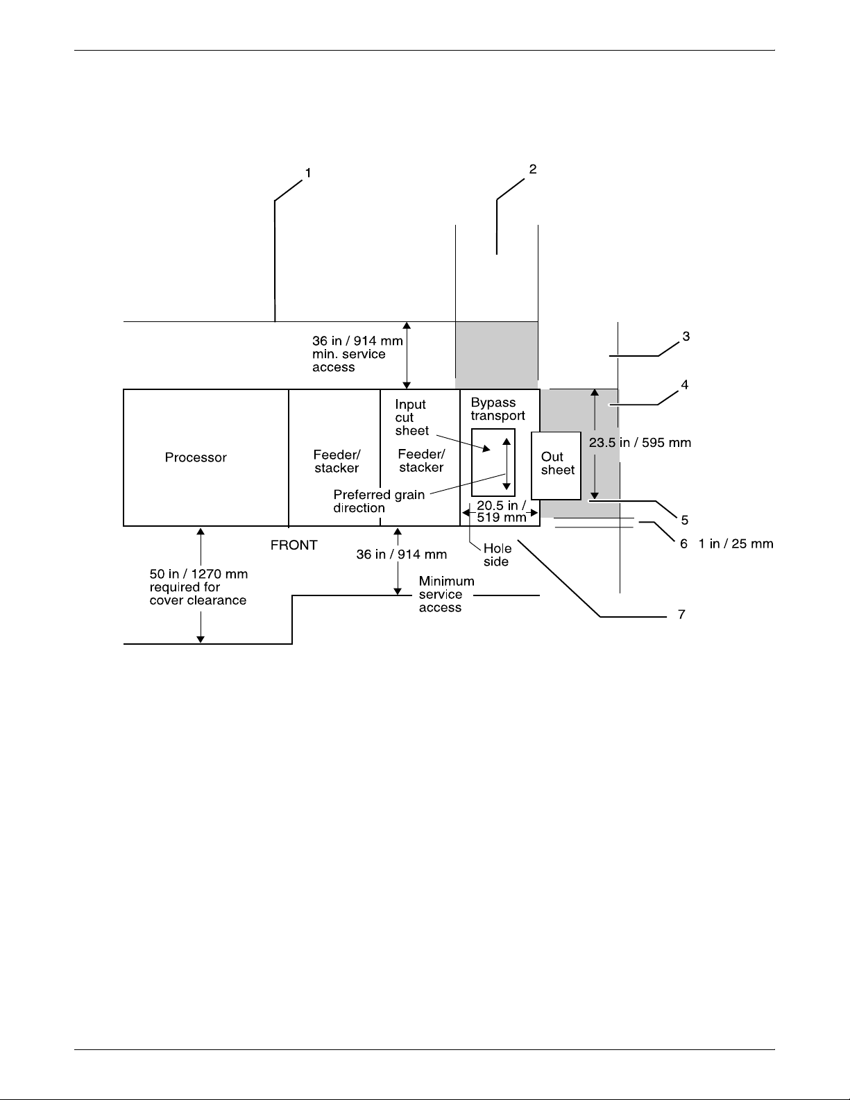
PRINTER SPECIFICATIONS AND REQUIREMENTS
Service access The following figure provides space planning information and service
access requirements for the bypass transport from a top view.
Figure 6-8. Bypass transport space planning diagram
1 Recommended third-party feeder hardware attaches at
rear of 96/4635/180 printer.
2 Expected third-party input paper feed path
3 Neutral area, to remain unoccupied
4 Shaded areas at rear and right side of the bypass transport
require third-party input/output devices to be undockable
from the feeder/stacker or the bypass transport.
5 Register edge of the output sheet
6 Third-party hardware must not extend more than 1 inch / 25
mm beyond bypass transport front cover line for correct
front door access.
7 Bypass transport / input enablement jam clearance space
is required.
6-14 XEROX DOCUPRINT 96/4635/180 IPS INSTALLATION PLANNING GUIDE
Page 73
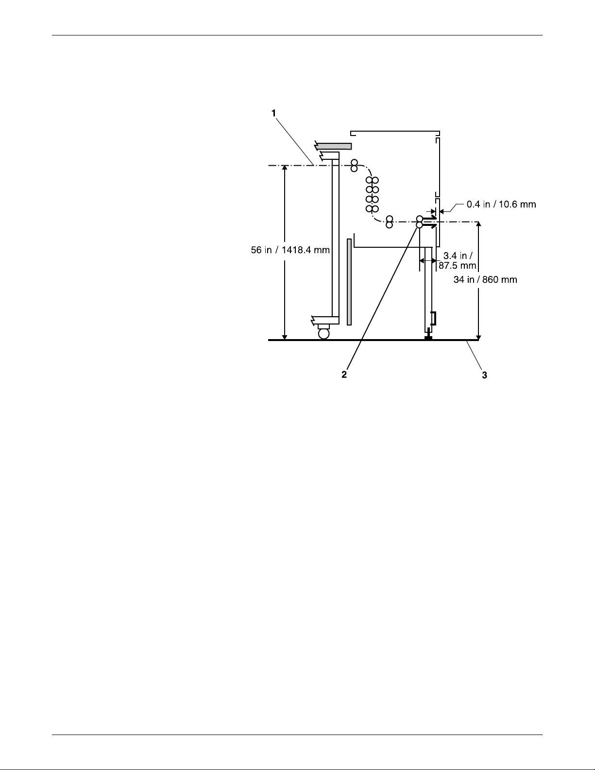
PRINTER SPECIFICATIONS AND REQUIREMENTS
Bypass transport paper path The following figure shows the paper path through the bypass
transport from a front view.
Figure 6-9. Bypass transport paper path
1 Sheet path
2 Exit rolls
3 Floor
XEROX DOCUPRINT 96/4635/180 IPS INSTALLATION PLANNING GUIDE 6-15
Page 74

PRINTER SPECIFICATIONS AND REQUIREMENTS
Input enablement dimensions The following figure shows the paper path and the dimensions of the
input enablement area from a printer front view. The input
enablement kit supports third-party feeding devices.
Figure 6-10. Input enablement paper path and dimensions
Bypass
transport
4 in / 101.5 mm
Frame datum
-A-
Floor
Area reserved for
input module
Sheet
entrance
guide
Cover
opening
2.4 in / 60.5 mm
7 in / 174.5 mm
17 in / 434 mm
17.1 in / 436.3 mm
695.5 mm
19.7 in /
500 mm
27.4 in /
Leg
assembly
6-16 XEROX DOCUPRINT 96/4635/180 IPS INSTALLATION PLANNING GUIDE
Page 75

Configuration diagrams with bypass transport
The following diagrams show the dimensions and space
requirements of the 96, 4635, and 180 with a bypass transport.
These diagrams represent top views of the components, surrounded
by the minimum access space requirements on all sides.
Figure 6-11. 96 printer—inverter feeder/stacker-only
PRINTER SPECIFICATIONS AND REQUIREMENTS
configuration with bypass transport
1
38.8 in /
98.6 cm
36 in /
91.4 cm
36 in / 91.4 cm
6
138 in /
350 cm
210 in / 533.4 cm
5
1 Back of system
2 Inverter
3 Feeder/stacker
4 Bypass transport
5 Front of system
6 Printer
32
19 in /
48.3 cm
4
91.4 cm
28.3 in /
71.9 cm
50 in /
127 cm
36 in /
114 in /
290.3 cm
XEROX DOCUPRINT 96/4635/180 IPS INSTALLATION PLANNING GUIDE 6-17
Page 76

PRINTER SPECIFICATIONS AND REQUIREMENTS
Figure 6-12. 96/4635/180 printer—inverter feeder/stacker +
feeder/stacker configuration with bypass transport
1
38.8 in /
98.6 cm
36 in /
91.4 cm
36 in / 91.4 cm
7
170 in /
431.8 cm
242 in / 614.7 cm
1 Back of system
2 Inverter
3 Feeder/stacker
4 Feeder/stacker
5 Bypass transport
6 Front of system
7 Printer
19 in /
48.3 cm
36 in /
91.4 cm
114 in /
28.3 in /
32
4
5
71.9 cm
290.3 cm
50 in /
127 cm
6
6-18 XEROX DOCUPRINT 96/4635/180 IPS INSTALLATION PLANNING GUIDE
Page 77

PRINTER SPECIFICATIONS AND REQUIREMENTS
Figure 6-13. 4635/180 printer—inverter feeder/stacker + feeder/
stacker + feeder/stacker configuration with bypass
transport
Back
38.8 in /
98.6 cm
36 in /
91.4 cm
36 in / 91.4 cm
8
32
202.25 in /
513.7 cm
275.5 in / 696.5 cm
7
1 Back of system
2 Inverter
3 Feeder/stacker
4 Feeder/stacker
5 Feeder/stacker
6 Bypass transport
7 Front of system
8 Printer
36 in /
91.4 cm
114 in /
54
28.3 in /
6
71.9 cm
290.3 cm
50 in /
127 cm
XEROX DOCUPRINT 96/4635/180 IPS INSTALLATION PLANNING GUIDE 6-19
Page 78

PRINTER SPECIFICATIONS AND REQUIREMENTS
Space planning guidelines
Clearance space requirements
When determining your space requirements and planning for shared
space between your printers, it is important to consider all of the
components you plan to install.
To ensure all of the space requirements are met, it is important to
work with your Xerox representative.
Before installation, you must consider the following:
• Clearance space requirements where you intend to install the
printer
• Recommended cable lengths and locations (refer to the
“System connections” chapter of this guide for more
information)
• Delivery access requirements
• Floor leveling.
Shared space
The printer must be installed in a fixed location that provides the
following clearance space:
• 36 inches / 91.4 cm on all sides of each component
• 24 inches / 61 cm of exclusive operator area in front of each
component
• 78 inches / 198 cm of vertical clearance throughout the entire
area.
Note: There must be a total of 50 inches / 126.9 cm of clearance
space in front of the printer.
It is best to provide the full amount of clearance space around the
hardware components. Your environment may require you to use
shared space between components, such as between the printer and
the printer controller or between the printer and another Xerox
printing system. You can share the 36-inch / 91.4 cm clearance
space around each component, as long as you follow these rules:
• Space may be shared only with other Xerox equipment.
• Components may share the 36-inch / 91.4 cm general service
clearance areas, but they may not share the 24-inch / 61 cm
operator area in front of each component.
• There must be 78 inches / 198 cm of vertical clearance
throughout the entire area.
Note: Finishers attached to your bypass transport and feeders
attached to your DocuPrint 4635, 96, or 180 printer through the input
enablement device may occupy shared space with Xerox equipment.
However, they must be removable to allow servicing of the DocuPrint
6-20 XEROX DOCUPRINT 96/4635/180 IPS INSTALLATION PLANNING GUIDE
Page 79

PRINTER SPECIFICATIONS AND REQUIREMENTS
4635, 96, or 180 printer feeders and stackers. Consult with your
Xerox representative to ensure all the requirements are met.
The following figures illustrate three possible configurations of
shared space.
Back-to-back shared space The figure below illustrates the two printers placed in a back-to-back
position. This allows them to share the entire 36 inches / 91.4 cm of
general service space.
Figure 6-14. Back-to-back shared service area space
192.6 in /
489.2 cm
2
1 Operator area
2 Printer
1
36 in / 91.4 cm
1
151.2 in / 384 cm
223.2 in / 567 cm
50 in /
127 cm
2
38.4 in /
97.5 cm
38.4 in /
97.5 cm
50 in /
127 cm
XEROX DOCUPRINT 96/4635/180 IPS INSTALLATION PLANNING GUIDE 6-21
Page 80
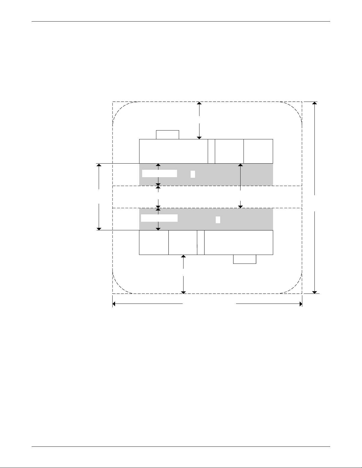
PRINTER SPECIFICATIONS AND REQUIREMENTS
Face-to-face shared space The following figure shows the two printers facing each other. The
printers share 12 inches / 30.5 cm of the general service space, but
not the exclusive operator area in front of each printer. Therefore, the
printers should be separated by 24 inches / 61 cm, plus 24 inches /
61 cm, plus 12 inches / 30.5 cm. This allows for the entire operator
space for each printer, plus the shared general service area of 12
inches / 30.5 cm.
Figure 6-15. Face-to-face shared service area space
36 in / 91.4 cm
2
74 in /
188 cm
24 in / 61 cm
26 in / 66 cm
24 in / 61 cm
36 in / 91.4 cm
1 Operator area
2 Printer
1
50 in / 127 cm
1
223.2 in / 567 cm
202.6 in /
514.6 cm
2
6-22 XEROX DOCUPRINT 96/4635/180 IPS INSTALLATION PLANNING GUIDE
Page 81
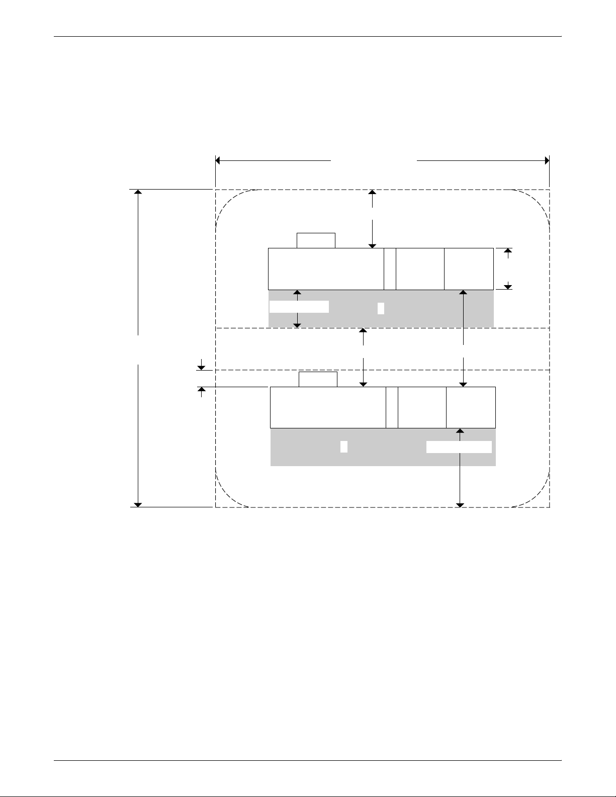
PRINTER SPECIFICATIONS AND REQUIREMENTS
Face-to-back shared space The following figure shows the two printers arranged with one facing
the back of the other. Between them is 60 inches / 152.4 cm of space.
This allows for 24 inches / 61 cm of operator space in front of the
printer facing toward the other, plus 36 inches / 91.4 cm of service
space behind the printer facing away from the other.
Figure 6-16. Face-to-back shared space
223.2 in / 567 cm
36 in / 91.4 cm
202.6 in /
514.6 cm
10.5 in /
26.7 cm
2
24 in / 61 cm
36 in / 91.4 cm
2
1
1 Operator area
2 Printer
28.3 in /
71.9 cm
1
66 in / 152.4 cm
50 in / 127 cm
XEROX DOCUPRINT 96/4635/180 IPS INSTALLATION PLANNING GUIDE 6-23
Page 82

PRINTER SPECIFICATIONS AND REQUIREMENTS
Floor leveling
For proper operation, the printer must be perfectly level. On floors
less than two degrees out of level, installation personnel use a
leveling kit to level the machine.
Note: The printer will not function properly on floors more than two
degrees out of level.
If the floor is more than two degrees out of level, this condition cannot
be corrected by the leveling kit. Another suitable location must be
found for the printer to be installed properly.
For your reference, two degrees represents a height discrepancy of
approximately 3.8 inches / 9.6 cm measured at the casters with the
printer tilting from left to right, or approximately 0.7 inches / 1.8 cm
with the printer tilting from back to front.
If you move the printer unit after its initial installation, it is your
responsibility to make sure that the printer can be leveled properly. If
you do not have the leveling kit (the printer in its initial location did not
require it), and you need one to level the printer in a new location,
contact your Xerox site representative to obtain one.
Delivery access requirements
It is easy to overlook the path required to move the equipment from
the truck to the operation site. To determine access, ask the following
questions:
• Does the equipment need to go up stairs?
• Do you have an elevator, if the equipment is to be located above
the first floor?
• Is the elevator large enough for the equipment?
• How wide are the hallways and doorways?
• Do you have a loading dock or a specific door to which the
equipment should be delivered?
You need to review these issues prior to, or at the time of, the site
inspection conducted by your service representative.
The equipment dimensions are specified earlier in this chapter, so it
is easy to determine whether your hallways and doorways are wide
enough to permit access.
6-24 XEROX DOCUPRINT 96/4635/180 IPS INSTALLATION PLANNING GUIDE
Page 83
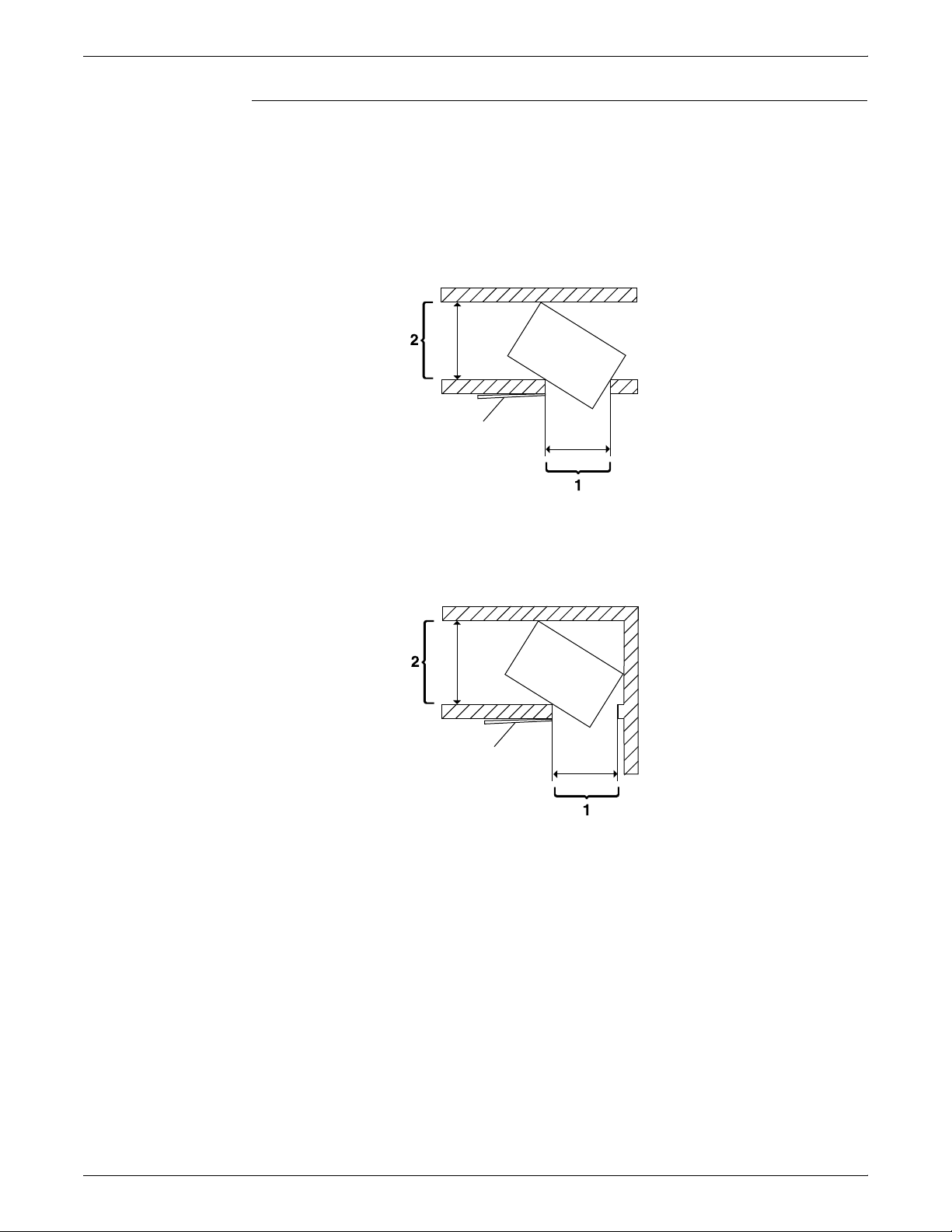
Turning radius
PRINTER SPECIFICATIONS AND REQUIREMENTS
You must also consider the width of the passageway when the
equipment must negotiate a corner, whether into a room, an elevator,
or another passageway.
There are L-shaped turns and T-shaped turns. The diagrams and the
tables that follow show the minimum space required to maneuver
through the turns.
Figure 6-17. T-shaped turn
1 Passage A
2 Passage B
Figure 6-18. L-shaped turn
1 Passage A
2 Passage B
Using the turning radius tables To use the tables:
1. Measure the minimum width of the passage or doorway you
need to use. This is Passage A.
2. Find that number (or the next higher number) in the turning
radius table and read across to the corresponding minimum
value for Passage B, depending on the type of turn the
equipment must negotiate.
XEROX DOCUPRINT 96/4635/180 IPS INSTALLATION PLANNING GUIDE 6-25
Page 84

PRINTER SPECIFICATIONS AND REQUIREMENTS
Turning radius for printer with
separated components
The 96, 4635 or 180 is delivered with the printer, inverter feeder/
stacker, and each feeder/stacker as separate modules. If necessary,
the printer can be separated into two pieces for ease in moving. The
larger of the two parts contains the xerographic system; the smaller
of the parts (the paper handling module, or PHM) contains paper
trays 1 and 2. Do not confuse these two parts of the printer with the
inverter and feeder/stacker modules, which have their own turning
requirements.
The following table lists the turning requirements for the printer
without the PHM (separated).
Table 6-7. Turning radius for printer (separated)
Passage or doorway A width Minimum passage B width
29 inches / 73.7 cm 74.5 inches / 189.2 cm
30 inches / 76.2 cm 64.5 inches / 163.8 cm
31 inches / 78.7 cm 62 inches / 157.5 cm
32 inches / 81.3 cm 59.5 inches / 151.1 cm
34 inches / 86.4 cm 56 inches / 142.2 cm
36 inches / 91.4 cm 53 inches / 134.6 cm
38 inches / 96.5 cm 50 inches / 127 cm
40 inches / 101.6 cm 48 inches / 121.9 cm
42 inches / 106.7 cm 45.5 inches / 115.6 cm
The following table lists the turning requirements for the printer if it is
upended for easier moving or stair-climbing. This table reflects
requirements for the printer separated from the PHM.
Table 6-8. Turning radius for printer (separated and upended
on dolly)
Passage or doorway A width Minimum passage B width
30 inches / 76.2 cm 49 inches / 124.5 cm
31 inches / 78.7 cm 43 inches / 109.2 cm
32 inches / 81.3 cm 41 inches / 104.1 cm
34 inches / 86.4 cm 37.5 inches / 95.3 cm
36 inches / 91.4 cm 35 inches / 88.9 cm
38 inches / 96.5 cm 33.5 inches / 85.1 cm
40 inches / 101.6 cm 32 inches / 81.3 cm
42 inches / 106.7 cm 31 inches / 78.7 cm
6-26 XEROX DOCUPRINT 96/4635/180 IPS INSTALLATION PLANNING GUIDE
Page 85
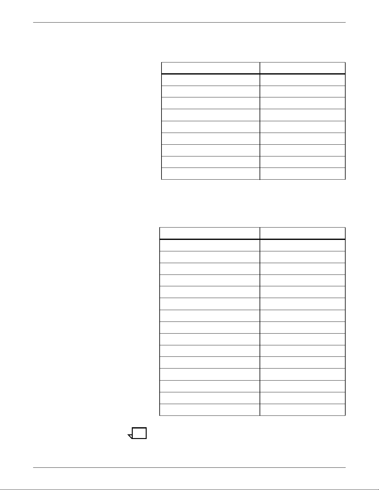
PRINTER SPECIFICATIONS AND REQUIREMENTS
Turning radius for unseparated
printer components
Turning radii for feeder/stacker
modules
The following table lists the turning requirements for the printer when
attached to the paper handling module (not separated).
Table 6-9. Turning radius for printer (not separated)
Passage or doorway A width Minimum passage B width
29 inches / 73.6 cm 83 inches / 210.8 cm
30 inches / 76.2 cm 76 inches / 193 cm
31 inches / 78.7 cm 73 inches / 185.4 cm
32 inches / 81.3 cm 70.5 inches / 179.1 cm
34 inches / 86.4 cm 66.5 inches / 169 cm
36 inches / 91.4 cm 63.5 inches / 161.3 cm
38 inches / 96.5 cm 61.5 inches / 156.2 cm
40 inches / 1,01.6 cm 58 inches / 147.3 cm
42 inches / 1,06.7 cm 55 inches / 139.7 cm
The following table lists the turning requirements for the inverter
feeder/stacker module.
Table 6-10. Turning radius for inverter feeder/stacker
module
Passage or doorway A width Minimum passage B width
29 inches / 73.7 cm 43 inches / 109.2 cm
30 inches / 76.2 cm 41 inches / 104.1 cm
31 inches / 78.7 cm 40 inches / 101.6 cm
32 inches / 81.3 cm 38 inches / 96.5 cm
33 inches / 83.8 cm 37 inches / 94 cm
34 inches / 86.4 cm 36 inches / 91.4 cm
35 inches / 88.9 cm 35 inches / 88.9 cm
36 inches / 91.4 cm 34 inches / 86.4 cm
37 inches / 94 cm 33 inches / 83.8 cm
38 inches / 96.5 cm 32 inches / 81.3 cm
39 inches / 99.1 cm 31 inches / 78.7 cm
40 inches / 101.6 cm 31 inches / 78.7 cm
41 inches / 104.1 cm 30 inches / 76.2 cm
42 inches / 106.7 cm 29 inches / 73.7 cm
43 inches / 109.2 cm 29 inches / 73.7 cm
Note: These turning figures are based on inverter/feeder/stacker
dimensions of 28 inches / 711 mm by 42 inches / 1,067 mm.
XEROX DOCUPRINT 96/4635/180 IPS INSTALLATION PLANNING GUIDE 6-27
Page 86
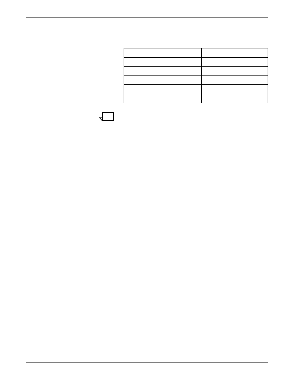
PRINTER SPECIFICATIONS AND REQUIREMENTS
The following table lists the turning requirements for the feeder/
stacker module.
Table 6-11. Turning radius for feeder/stacker module
Passage or doorway A width Minimum passage B width
29 inches / 73.7 cm 33 inches / 83.8 cm
30 inches / 76.2 cm 32 inches / 81.3 cm
31 inches / 78.7 cm 31 inches / 78.7 cm
32 inches / 81.3 cm 30 inches / 76.2 cm
33 inches / 83.8 cm 29 inches / 73.7 cm
Note: These turning figures are based on inverter/feeder/stacker
dimensions of 28 inches / 71.1 cm by 32.25 inches / 81.9 cm.
6-28 XEROX DOCUPRINT 96/4635/180 IPS INSTALLATION PLANNING GUIDE
Page 87

PRINTER SPECIFICATIONS AND REQUIREMENTS
Printer hardware specifications and requirements summary
The following table summarizes the specifications and electrical
requirements of your printer hardware components.
For a summary of controller hardware specifications and
requirements, refer to the “Controller specifications and
requirements” chapter of this guide. Contact your service
representative if you have questions not specifically addressed in this
guide.
Table 6-12.Printer specifications and power requirements—96/
4635/180
Device
96 printer:
Inverter feeder /
stacker only
96/4635/180
printer:
Inverter feeder /
stacker + feeder /
stacker
Dimensions (depth,
width, height) Weight
d=38.8 in. / 98.6 cm
w=119 in./ 302.3 cm
h= 59.6 in. / 151.3 cm
Total space
required (+ access):
191 in. w by
114 in. d /
567 cm w by
290.3 cm d
d=38.8 in. / 98.6 cm
w=151.2 in./ 384 cm
h= 59.6 in. / 151.3 cm
Total space
required (+ access):
223.25 in. w by
114 in. d /
567 cm w by
290.3 cm d
1925 lbs. /
874 kg
2,588 lbs. /
1,174.9 kg
Heat
dissipation Power requirements
Operating:
28,140
BTU per
hour
Standby:
4,454
BTU per
hour
96/4635:
Operating:
28,140
BTU per
hour
Standby:
4,454
BTU per
hour
Energy
Saver: 2,700
BTU per
hour
180:
Operating:
32,770
BTU per
hour
Standby:
4,454
BTU per
hour
60 Hz:
120/208 VAC
(182 V to 220 V),
KVA 7.3 (operating)
Power cord: 50 amp,
NEMA 14-50R
50 Hz:
Consult your
local service
representative.
60 Hz:
96/4635:
120/240 VAC or
120/208 VAC;
50 amp service;
NEMA L14-50R;
KVA 7.3 (operating)
180:
120/208 VAC
(182 V to 220 V),
KVA 7.3 (operating)
Cord 1: 50 amp,
NEMA 14-50R
Cord 2: 30 amp,
NEMA 14-30R
Consult your
50 Hz:
local service
representative.
Energy
Saver: 2,700
BTU per
hour
XEROX DOCUPRINT 96/4635/180 IPS INSTALLATION PLANNING GUIDE 6-29
Page 88
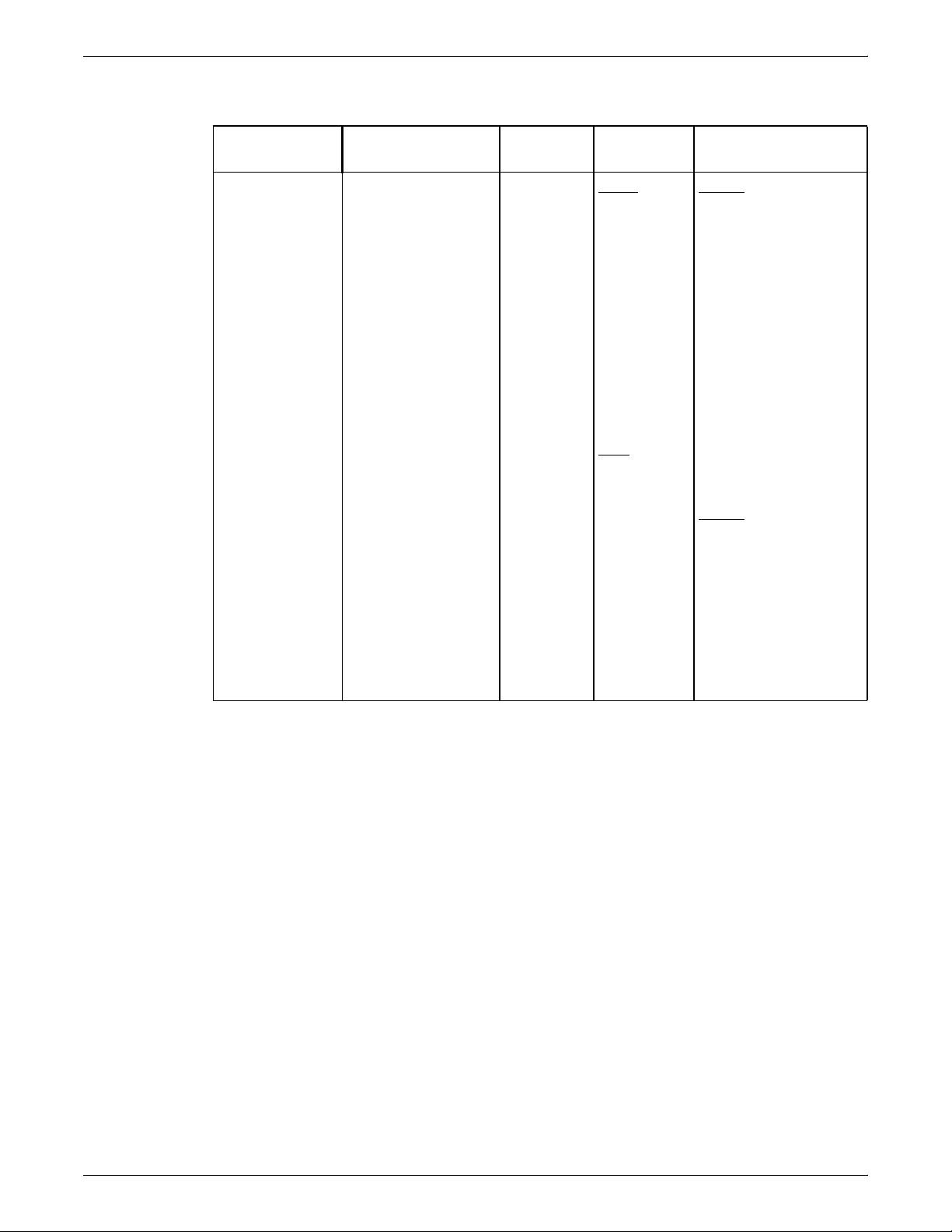
PRINTER SPECIFICATIONS AND REQUIREMENTS
Table 6-12.Printer specifications and power requirements—96/
4635/180 (continued)
Device
4635/180
printer:
Inverter feeder /
stacker + two
feeder / stackers
Dimensions (depth,
width, height) Weight
d=38.8 in. / 98.6 cm
w=183.5 in./ 466.1cm
3,109 lbs. /
1,411.9 kg
h=59.6. in. / 151.3 cm
Total space
required (+ access):
256.5 in. w by
114 in. d /
648.9 cm w by
290.3 cm d
Heat
dissipation Power requirements
4635:
Operating:
28,140
BTU per
hour
Standby:
4,454
BTU per
hour
Energy
Saver: 2,700
BTU per
hour
180:
Operating:
32,770
BTU per
hour
60 Hz:
4635:
120/240 VAC or
120/208 VAC;
50 amp service;
NEMA 14-50R,
KVA 8.1(operating)
180:
120/208 VAC
(182 V to 220 V),
KVA 8.1(operating)
Cord 1: 50 amp,
NEMA 14-50R
Cord 2: 30 amp,
NEMA 14-30R
50 Hz:
Consult your
local service rep.
Standby:
4,454
BTU per
hour
Energy
Saver: 2,700
BTU per
hour
6-30 XEROX DOCUPRINT 96/4635/180 IPS INSTALLATION PLANNING GUIDE
Page 89

PRINTER SPECIFICATIONS AND REQUIREMENTS
Table 6-12.Printer specifications and power requirements—96/
4635/180 (continued)
Device
4635/180
printer:
Inverter feeder /
stacker + three
feeder / stackers
Dimensions (depth,
width, height) Weight
d=38.8 in. / 98.6 cm
w=216 in. / 730.8 cm
3,630 lbs. /
1,648.9 kg
h=59.6 in. / 151.3 cm
Total space
required (+ access):
287.75 in. w by
114 in. d/
730.8 cm w by
290.3 cm d
Heat
dissipation Power requirements
4635:
Operating:
28,140
BTU per
hour
Standby:
4,454
BTU per
hour
Energy
Saver: 2,700
BTU per
hour
180:
Operating:
32,770
BTU per
hour
60 Hz:
4635:
120/240 VAC or
120/208 VAC;
50 amp service;
NEMA 14-50R,
KVA 8.8 (operating)
180:
120/208 VAC
(182 V to 220 V),
KVA 8.8 (operating)
Cord 1: 50 amp,
NEMA 14-50R
Cord 2: 30 amp,
NEMA 14-30R
50 Hz:
Consult your
local service rep.
Standby:
4,454
BTU per
hour
Bypass
transport
d=28.3 in. / 71.9 cm
w=20.4 in. / 51.9 cm
h=56.1 in. / 142.5 cm
176 lbs. /
80 kg
Energy
Saver: 2,700
BTU per
hour
--- ---
XEROX DOCUPRINT 96/4635/180 IPS INSTALLATION PLANNING GUIDE 6-31
Page 90

PRINTER SPECIFICATIONS AND REQUIREMENTS
Space planning templates
The dimensions and space requirements for your printer components
are provided earlier in this chapter. The space planning templates
are designed to simplify the space planning process by helping you
to create a floor plan for your base components, particularly if you
have shared clearance space.
The easiest way to use the space planning templates is to move the
templates around on the grid located at the end of this section and
determine the optimum placement for your printer components.
Make sure to consider other pieces of equipment, such as cabinets,
tables, and optional equipment when planning your space. Your
customer support representative can help you plan space for
additional components.
The templates are to scale with the grid; each square is equal to 12
by 12 inches/30.5 by 30.5 cm. The curved dotted lines in the corners
of the space perimeters indicate the corners that may be rounded off
while still maintaining the required clearance space.
There are a number of factors to keep in mind when planning your
site, including the following:
• Clearance space requirements
• Cable length.
Refer to these sections in this manual when considering the various
factors involved in planning the appropriate location for your printing
system.
When determining your space requirements, remember to consider
all of the components you plan to have installed. If you have a bypass
transport or input enablement device option on your printing system,
you should contact the sales representatives for the company from
which you purchased your finishers and feeders, as well as your
Xerox representative, to ensure that all of your space requirements
are met.
6-32 XEROX DOCUPRINT 96/4635/180 IPS INSTALLATION PLANNING GUIDE
Page 91
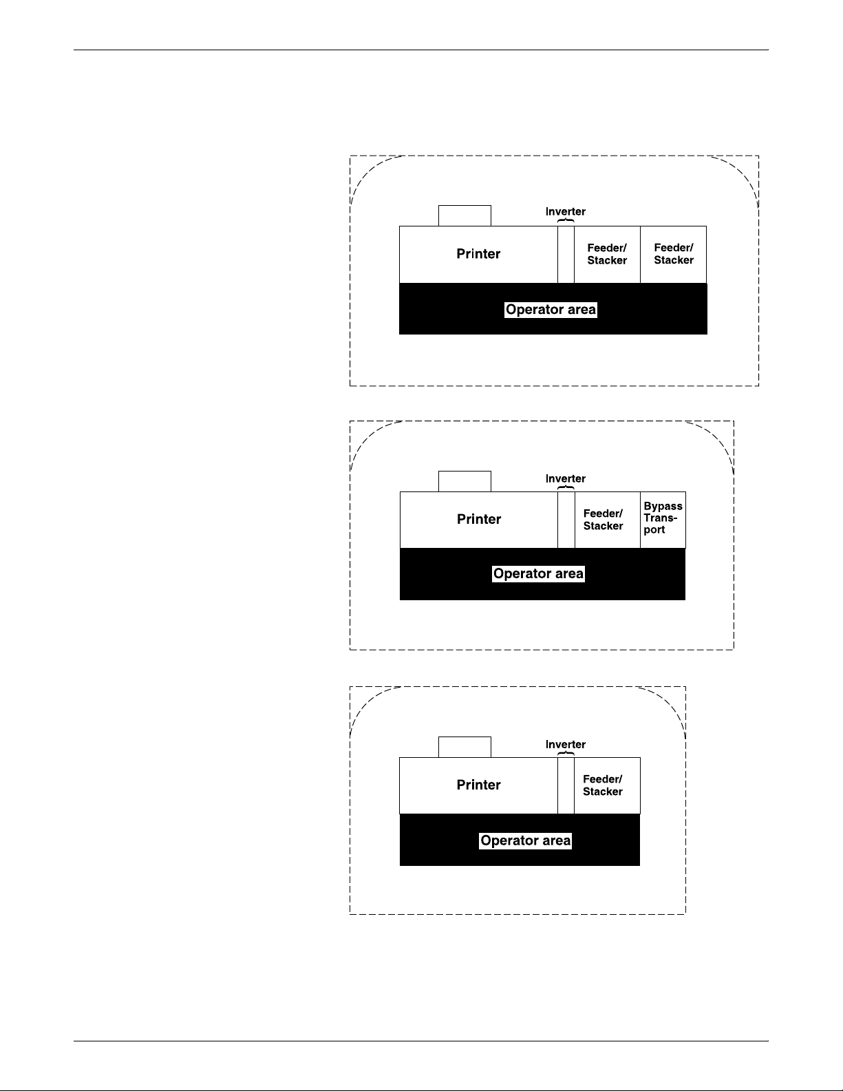
PRINTER SPECIFICATIONS AND REQUIREMENTS
XEROX DOCUPRINT 96/4635/180 IPS INSTALLATION PLANNING GUIDE 6-33
Page 92

PRINTER SPECIFICATIONS AND REQUIREMENTS
6-34 XEROX DOCUPRINT 96/4635/180 IPS INSTALLATION PLANNING GUIDE
Page 93

PRINTER SPECIFICATIONS AND REQUIREMENTS
XEROX DOCUPRINT 96/4635/180 IPS INSTALLATION PLANNING GUIDE 6-35
Page 94

PRINTER SPECIFICATIONS AND REQUIREMENTS
6-36 XEROX DOCUPRINT 96/4635/180 IPS INSTALLATION PLANNING GUIDE
Page 95

PRINTER SPECIFICATIONS AND REQUIREMENTS
XEROX DOCUPRINT 96/4635/180 IPS INSTALLATION PLANNING GUIDE 6-37
Page 96

PRINTER SPECIFICATIONS AND REQUIREMENTS
6-38 XEROX DOCUPRINT 96/4635/180 IPS INSTALLATION PLANNING GUIDE
Page 97
GRID PATTERN
2 3 4 5 6 7 8 9 10 11 12 13 14
1
C
u
t
1/4 inch represents one foot
15 16 17 18 19 20 21 22 23 24 25 26 27 28
1
2
3
4
5
6
7
8
9
10
11
12
O
D
o
e
d
L
n
e
13
n
t
t
i
14
15
16
17
18
19
20
21
22
23
24
25
26
27
28
29
30
31
32
33
34
35
36
37
38
39
40
Page 98

Page 99
Cable lengths
7. 7System connections
This chapter provides cable requirements for your 96/4635/180 IPS
system. It also provides information about channel-attaching your
IPS printer. To ensure all of your cable requirements are met, it is
important to work with your Xerox representative.
Cable lengths are important considerations in planning your layout,
as components can be separated only up to the length of the data
interface cables that connect them.
Cables supplied with the printer are of sufficient length to meet the
needs of most installations. Some of these cables are specific
lengths to conform to engineering and safety standards.
Data cables The printer components can be separated up to the length of the data
interface cables that connect them. The printer and controller are
connected by a 25-foot / 7.6 meter data cable.
Power cables The 96/4635/180 power cable lengths are as follows:
Table 7-1. Power cable lengths
Power cable Length
Printer controller 8 feet / 2.1 m
Printer 15 feet / 4.4 m
Warning: Using an inappropriate alternate cable may degrade the
!
performance of your equipment and may also be hazardous.
Note: Cable length loss must be factored in if equipment is installed
in a raised-floor environment. You should also consider that part of
the length of a cable is routed inside the equipment to connect with
interior power or data receptacles.
XEROX DOCUPRINT 96/4635/180 IPS INSTALLATION PLANNING GUIDE 7-1
Page 100
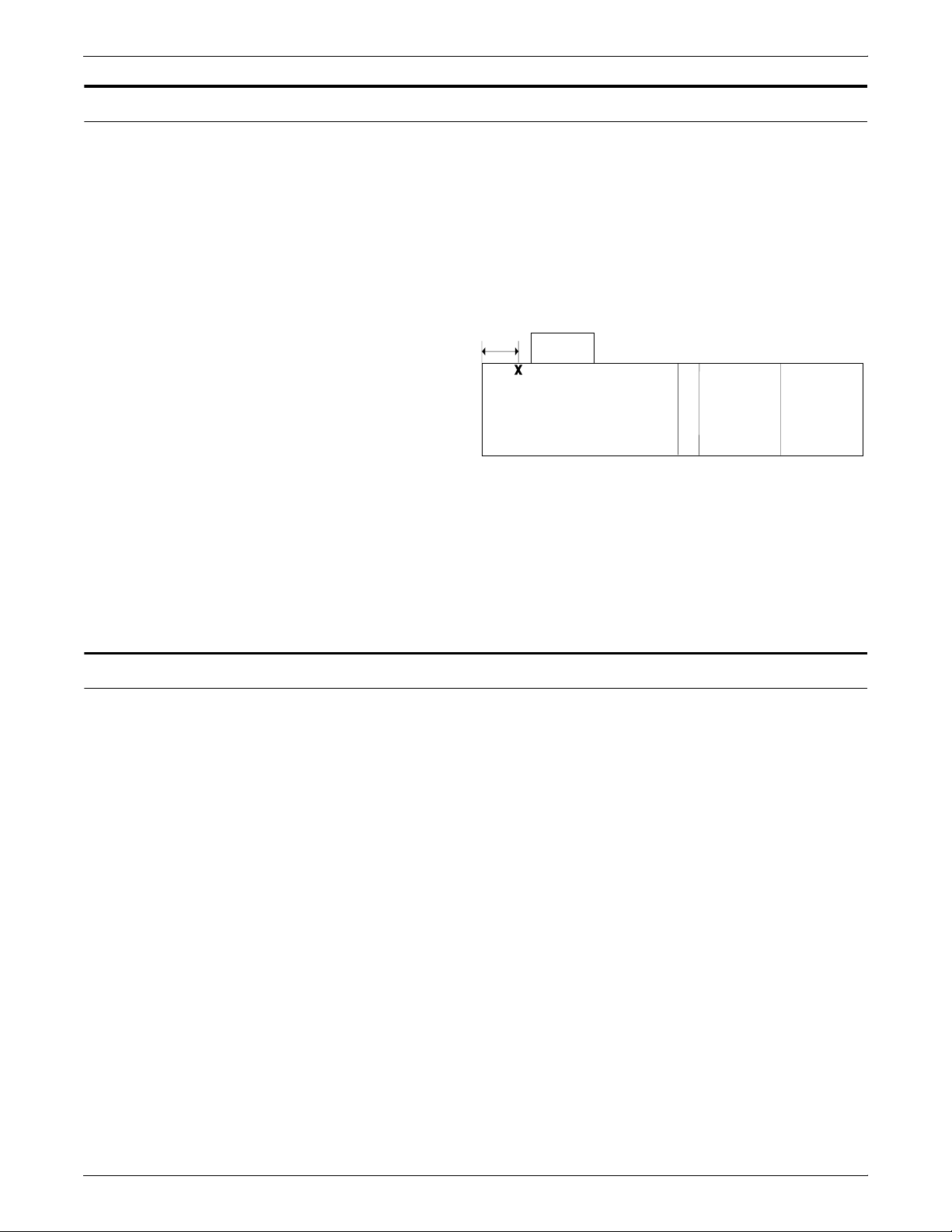
SYSTEM CONNECTIONS
Cable locations
To run the cables beneath the flooring effectively, it is necessary to
know where the cables enter and exit the printer. The following
diagrams show those locations (marked with an X).
All power cords attach to the back of the printer. Listed below are the
distances of the printer power cord attachments from the left end of
the printer as you face it.
Figure 7-1. 96/4635/180 cable enter/exit location (top view)
Back
14"/356 mm
Printer with
feeder/stacker
modules
Channel attachments
Front
Operator area
• 180 power cord attachments—distance from end of printer:
— Cord 1: 36 inches / 914 mm (with ELCI)
— Cord 2: 23 inches / 584 mm (with ELCI)
• 96 and 4635—distance from end of printer: 14 inches / 356 mm
The IPS printing system conforms to IBM standards and
requirements for any channel-attached printer. When you channelattach your printer, keep the following in mind:
• Channel length is usually determined by the length of the
cables, the number of devices on the channel, and the number
of connections in the cable itself (for example, connecting two
cables to each other).
• Subtract 15 feet from the total allowable cable length for any
device attached to the channel or for any connection of two
cables.
• IBM channel cable lengths are as follows:
— Gray: 200 feet / 61 m (with one device, 185 feet / 56 m)
— Blue: 400 feet / 122 m (with one device, 385 feet / 117 m)
For further information regarding IBM channel connections, refer to
the following IBM manuals:
• IBM System 360 and System 370 Input-output Interface
Channel to Control Unit OEM Information (#GA22-6974-3825)
• Page Printer Product Description (#G544-3482)
• 3825 Introduction and Planning Guide (#G544-3480).
7-2 XEROX DOCUPRINT 96/4635/180 IPS INSTALLATION PLANNING GUIDE
 Loading...