

Page 1
GBC
FusionPunch II
User Guide
Manuale dell’utente
Bedienungsanleitung
Gebruikershandleiding
Guide d’opération
Guía del usuario
Page 2

©2001 General Binding Corporation. All rights reserved.
©2001 General Binding Corporation. Tutti i diritti riservati.
©2001 General Binding Corporation. Alle Rechte vorbehalten.
©2001 General Binding Corporation. Alle rechten voorbehouden.
©2001 General Binding Corporation. Tous droits réservés.
©2001 General Binding Corporation. Todos los derechos reservados.
Page 3

Table of Contents
Book 1 - GBC FusionPunch II User Guide - English
Libro 2 - GBC FusionPunch II Manuale dell’utente - Italiano
Buch 3 - GBC FusionPunch II Bedienungsanleitung - Deutsch
Boek 4 - GBC FusionPunch II Gebruikershandleiding - Nederlands
Livre 5 - GBC FusionPunch II Guide d’opération - Français
Libro 6 - GBC FusionPunch II Guía del usuario - Español
FusionPunch II User Guide Table of Contents
Page 4

Table of Contents FusionPunch II User Guide
Page 5
GBC
FusionPunch II
User Guide
Page 6

Page 7

Table of Contents
Preface
Safety Messages v
Important Safeguards vii
Service vii
Cleaning viii
Chapter 1: Getting Started
About the FusionPunch II 1-3
Punch any hole pattern 1-3
Online 1-3
At the speed of your printer 1-3
Key Features 1-4
Specifications 1-5
Control Functions and Locations 1-6
The Control Panel 1-6
Creating 61XX Profiles and Print Queues 1-11
What is a Profile? 1-11
What is a Print Queue? 1-11
System Access for Setup 1-11
61XX Log On 1-12
61XX Profile Setup 1-14
61XX Print Queue Setup 1-24
GBC Punch Queue Output 1-27
GBC Short Edge Punch Queue Output 1-28
SBM1/SBM2 Queue Output 1-29
Chapter 2: General Procedures
Changing Die Sets 2-3
Removing and Replacing Die Pins 2-6
Centering the Punch 2-7
Setting the Side Guide 2-9
Setting the Backgauge 2-12
Starting a Job 2-14
Punching and Stacking 2-14
Bypassing to a Downstream device 2-20
Using the GBC Stacker 2-26
FusionPunch II User Guide Table of Contents
Page 8

Chapter 3: Troubleshooting
Clearing Jams 3-3
Error Messages from the Printer 3-5
Error Messages from the FusionPunch II 3-7
Error Messages from downstream devices 3-13
Chapter 4: Maintenance
Cleaning the FusionPunch II 4-3
When to Clean 4-3
What to Use 4-4
What to Clean 4-4
Cleaning the Punch 4-5
Cleaning the Stacker 4-8
Cleaning the Bypass 4-9
Appendix A: Personality Profiles
Contents A-3
Personality Profiles A-5
Standard Punch Profiles A-5
Other Known Configurations A-8
Glossary
Glossary of Common FusionPunch II Terms G-3
Table of Contents FusionPunch II User Guide
Page 9
Preface
SAFETY MESSAGES
The safety of you and others is very important to GBC. Important safety
messages and information are contained within this Operating Instructions
manual as well as on the machine itself. Please be certain to carefully read
and understand all of these before operating the machine.
The safety alert symbol precedes each safety message in this Operating
Instructions manual. This symbol indicates a potential personal safety
hazard that could result in injury to you or others as well as cause product
or property damage.
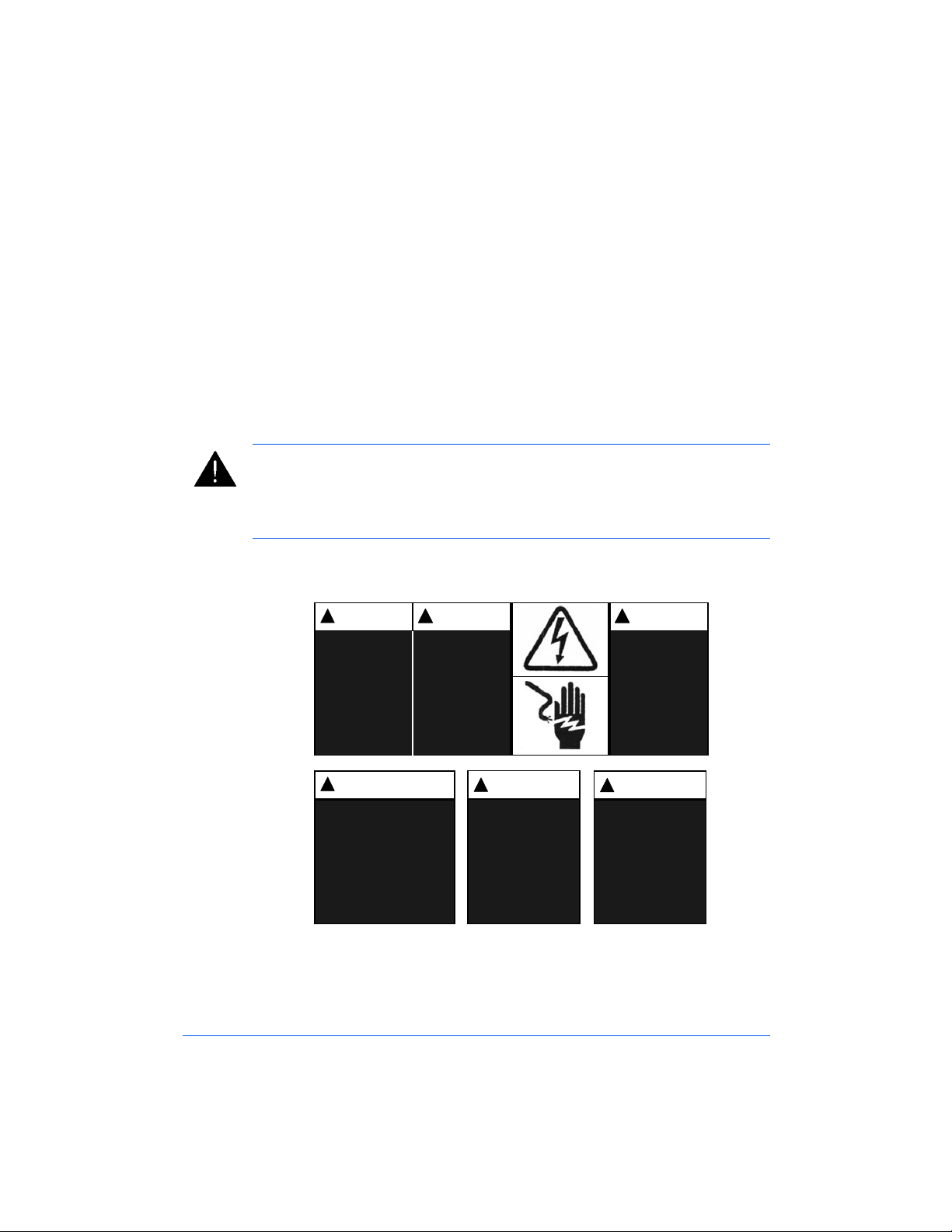
The following pictorial is found on the FusionPunch II:
MUCHO
!
CUIDADO
Riesgo de choque
eléctrico.
No abra.
Adentro, no hay
piezas reparables
para el usuario.
Mantenimiento
solamente para
personal calificado.
!
ATTENTION
Risque de secousse
électrique.
Ne pas ouvrir.
Pas de pièces
réparables par
l'utilisateur.
Entretien par
personnel qualifié.
!
WARNING
Electrical shock
hazard.
Do not open.
No user serviceable
parts inside.
Refer servicing to
qualified service
personnel.
!
WAARSCHUWING
Kans op elektrische schok.
Niet openen.
Bevat geen door gebruik te
repareren onderdelen.
Door bevoegd
servicepersoneel laten
repareren
ATTENZIONE
!
Pericolo di scarica
elettrica.
Non aprire.
Nessuna parte
riparabile dall'utente.
Chiamare un servizio di
riparazioni qualificato.
WARNUNG
!
..
Spannungsfuhrende
Teile.
Nicht offnen.
Enthali keine vom
Endverbrucher zu
wartende Teile.
Fur Service bitte an
qualifiziertes
Service-Personal
wenden.
..
..
..
This safety message indicates that you could be seriously hurt or killed if
you open the product and expose yourself to hazardous voltage. NEVER
FusionPunch II User Guide Preface v
Page 10

remove the machine’s outer covers. ALWAYS refer service requirements to
qualified GBC personnel.
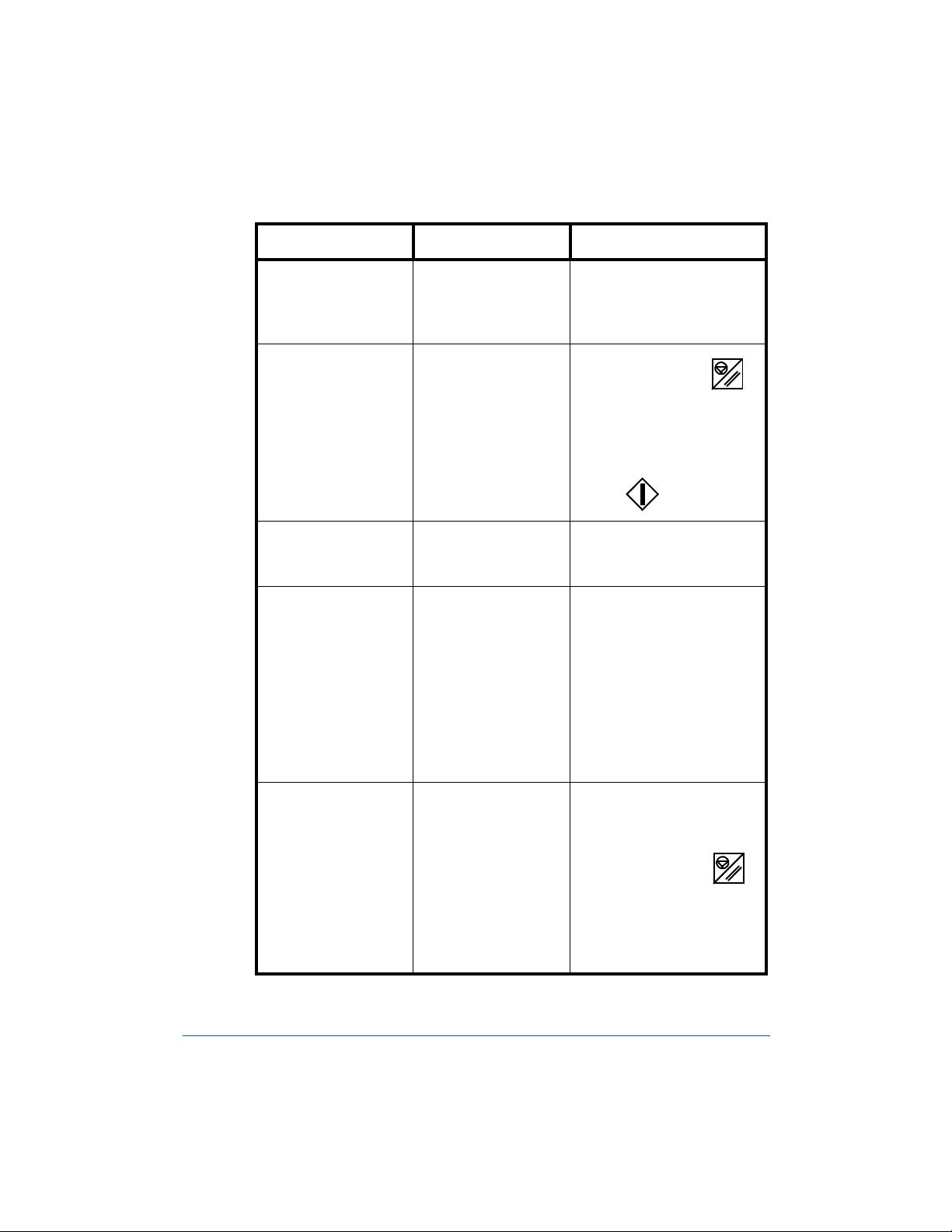
The following ISO and IEC symbols appear on this product. Their meaning
is:
I Means Power ON.
O Means Power OFF.
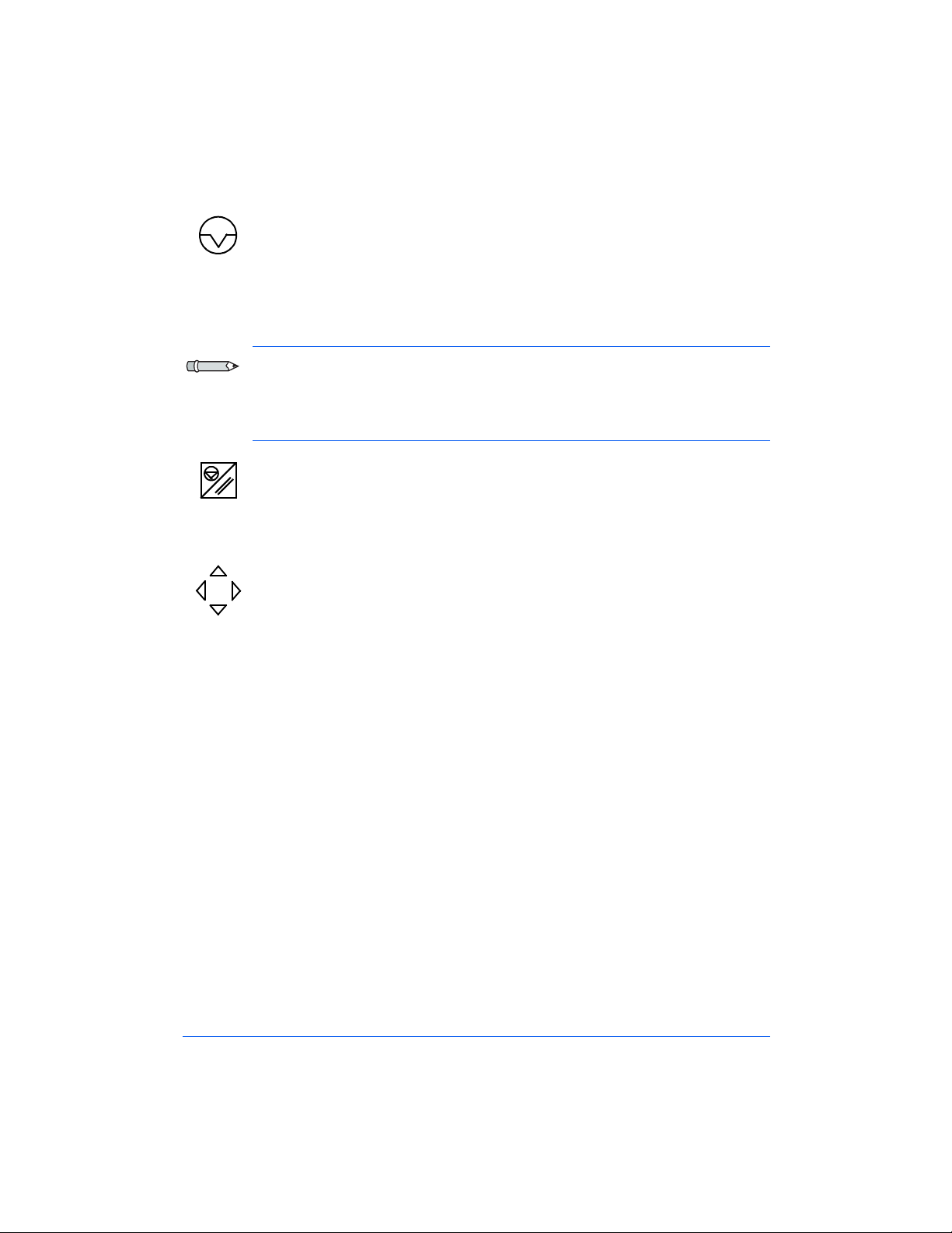
Means START.
"DIAGNOSTICS"
"ONLINE/OFFLINE"
Means you can select a preferred language (also used by Service
Personnel).
Means the machine can run in conjuction with the printer or run
without the printer. Also used to set up the machine in different
configurations.
Means Raise or Lower Stacker.
Means INTERRUPT the job that you are running.
Means STOP.
Means RESET.
IMPORTANT SAFEGUARDS
Use the FusionPunch II only for its intended purpose of punching
n
paper and covers according to the indicated product specifications.
Retain this Operating Instructions manual for later use.
n
Preface vi FusionPunch II User Guide
Page 11

CAUTION: In case of emergency, use the power cord as a main disconnect
device!
The FusionPunch II must be connected to a supply voltage
n
corresponding to the electrical rating in the machine operating
instructions (also listed on the serial number label).
The socket-outlet shall be located near the equipment and shall be
n
easily accessible.
The grounding plug is a safety feature and will only fit into the proper
n
grounding-type power outlet. If you are unable to insert the plug into an
outlet, contact a qualified electrician to have a suitable outlet installed.
Do not alter the plug on the end of the cordset (if provided) of the
FusionPunch II. It was provided for your safety.
Unplug the FusionPunch II before moving the machine or whenever
n
the machine is not in use for an extended period of time.
Do not operate the FusionPunch II if the machine has a damaged
n
power supply cord or plug. Do not operate the machine after any
malfunction, if liquid has been spilled into the machine, or if the
machine has been damaged in any way.
Do not overload electrical outlets beyond their capacity. To do so can
n
result in fire or electrical shock.
SERVICE
Do not attempt to service your FusionPunch II yourself. Contact an
n
authorized GBC service representative for any required repairs or major
maintenance for your FusionPunch II.
DO NOT REMOVE THE MACHINE’S COVERS
There are NO user-serviceable parts inside the machine. Removal of the
n
covers by the user could result in potential personal injury and/or
property or machine damage.
FusionPunch II User Guide Preface vii
Page 12

CLEANING
You may clean the exterior of the FusionPunch II using a soft, damp
n
cloth. Do not use detergents or solvents as damage to the machine may
occur.
Preface viii FusionPunch II User Guide
Page 13

Getting Started
About the FusionPunch II
Control Functions and Locations
Using the Control Panel
Chapter 1
1
Creating 61XX Profiles and Print Queues
What is a Profile?
What is a Print Queue?
System Access for Setup
DocuTech 135 Host Enablement
(refer to Appendix A)
Xerox 4XXX Host Enablement
(refer to Appendix A)
Page 14

1-2 Getting Started
Page 15

About the FusionPunch II
The GBC FusionPunch II is a new and improved online printer punch that
has been redesigned to meet Xerox certification. It is the only online printer
punch on the market today. The FusionPunch II features easy, automated
operation.
Punch any hole pattern
The FusionPunch II features multiple punching dies that can be changed in
minutes without the use of tools. Die sets are available in a variety of
standard configurations such as Three Hole, GBC Plastic and TwinLoop
Custom dies can be built to order.
Online
The FusionPunch II attaches directly to your high-speed printer.
Documents flow directly from the printer to the binding system without the
bottleneck associated with traditional offline punching processes. The
FusionPunch II online punching system not only affords superior
turnaround times, but also significantly reduces labor costs. Only one
operator is required to print, punch and offset stack documents.
TM
.
1
At the speed of your printer
The FusionPunch II matches the speed of your printer, punching over 200
sheets per minute. This is faster than the production rate of the fastest cut
sheet printer on the market today.
About the FusionPunch II 1-3
Page 16
Key Features
1
Die sets can be easily changed without tools.
2 Paper size adjustments can be made quickly and easily.
3 The Single Sheet Feeder design of the FusionPunch II maintains
document integrity and allows the operator to set up the machine in
offline mode.
4 The Output Stacker allows documents to emerge punched and offset
stacked for more efficient offline binding operations. One or more
stackers can be connected for continuous operation.
5 An optional Bypass Stacker can be used inline to allow the use of other
downline finishers, such as a Signature Booklet Maker, or BDFX.
2
3
1
4
5
1-4 Getting Started
Page 17

Specifications
Printer DocuTech 135, 6100, 6115, 6135, 6155 and 6180.
DocuPrint 4050, 4090, 4135, 4180, 4635, 4850 and 4890.
Supported Sheet Size Productivity
Punching Long Edge
8.5 x 11/A4 All printers run at the rated speed of the printer.
(Including Index Tabs and 9" Covers)
Punching Short Edge
(*) 8.5 x 11/A4 All printers run at the rated speed of the printer
except for the DT 6180. (DT 6180 is slightly slower due to
a skip pitch introduced in the printer.)
(*) 8.5 x 14 All printers run at the rated speed of the printer
except for the DT 6180. (DT 6180 is slightly slower due to
a skip pitch introduced in the printer.)
(#) 11 x 14 All printers run at the rated speed of the printer
except for the DT 6180. (DT 6180 is slightly slower due to
a skip pitch introduced in the printer.)
(#) 11 x 17/A3 All printers run at the rated speed of the printer.
Denotations:
(*) Requires a GBC Bypass Stacker and a Xerox High
Capacity Stacker.
(#) Requires a GBC Stacker without the Bypass or a GBC
Bypass Stacker and a Xerox High Capacity Stacker.
Paper Stock 60 gsm Bond to 200 gsm Index.
Output Stacker Each stacker holds 2500 sheets.
Dimensions 81 inches (2058 mm) L x 32 inches (813 mm) W x 56
inches (1422 mm) H.
Wei g ht Punch: 620 lbs. (281 kg.)
Stacker: 270 lbs. (123 kg.)
Bypass Stacker: 320 lbs. (145 kg.)
Power Supply USA/Canada - Punch: 115 VAC, 60 Hz, 4.7 amps.
Stacker: 115 VAC, 60 Hz, 1.0 amps.
International - Punch: 230 VAC, 50 Hz, 6.8 amps.
Stacker: 230 VAC, 50 Hz, 0.25 amps.
Temperature Range 41 - 104 Degrees F. (5 - 40 Degrees C.)
Humidity Range 30% - 95%, non-condensing.
Altitude 3280 feet (1000 meters).
1
About the FusionPunch II 1-5
Page 18
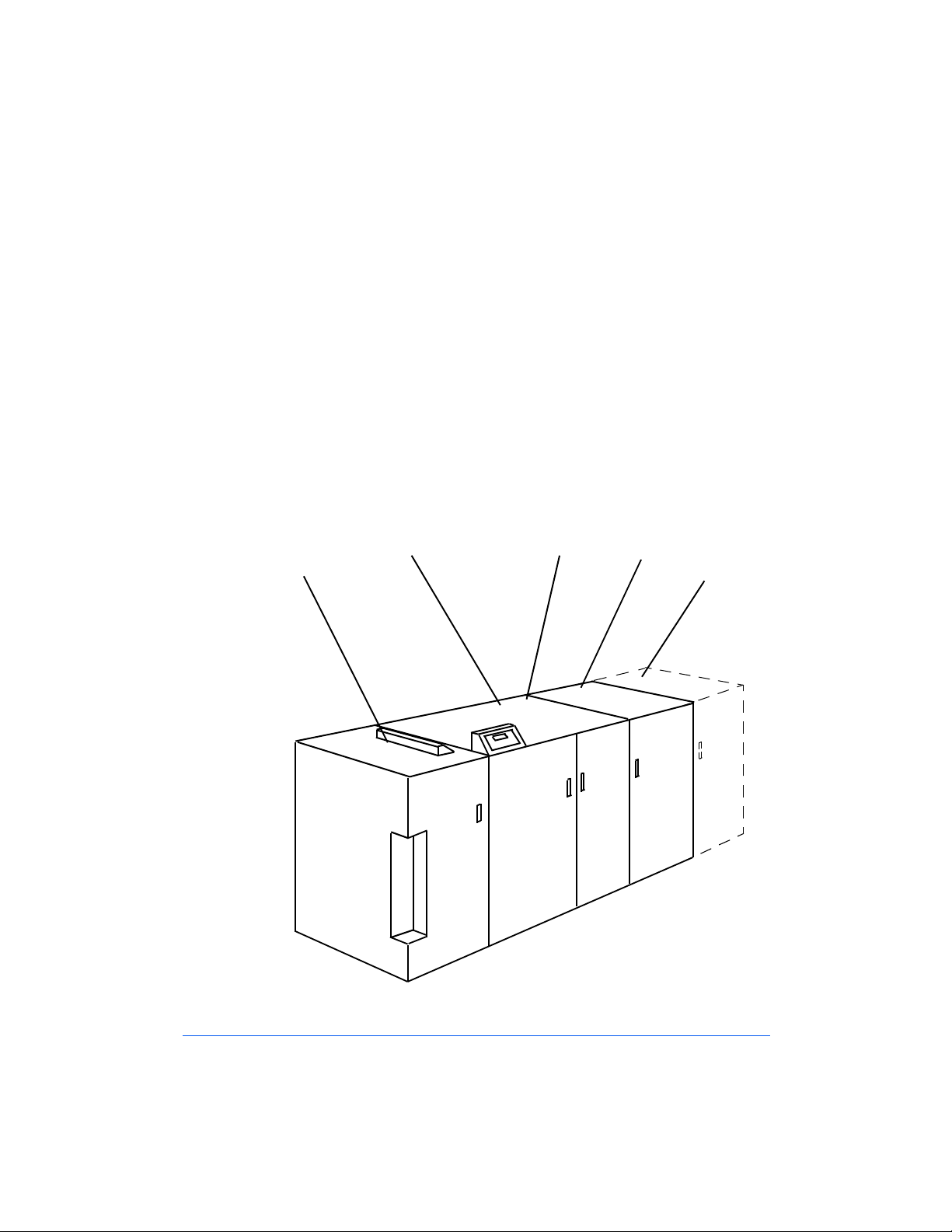
Control Functions and Locations
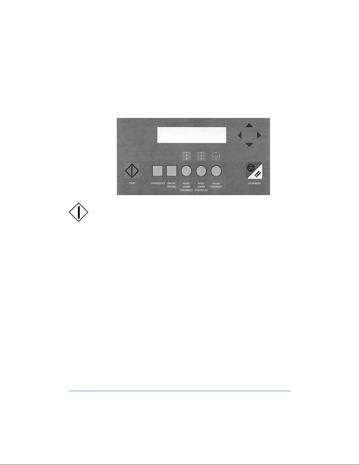
The Control Panel
The FusionPunch II Control Panel
1
Start
The Start button is used to start a job and to begin punching
in offline mode.
"DIAGNOSTICS"
1-6 Getting Started
2
Diagnostics
The Diagnostics button is used by service personnel to run
diagnostics when the machine requires service.
The Diagnostics button also has another feature known as
User Functions. To use this feature, perform the following
steps:
a. Press the Diagnostics button once. Version Control
information displays, to include the current version level
of the machine’s software.
b. Press the Diagnostics button again. The Punch Count is
displayed.
c. Press the Diagnostics button again.The current language is
displayed. To change languages, do the following:
Page 19

Use the Up and Down Arrows to scroll through the
n
listing of available languages. They are: English,
Spanish, German, French, Italian and Dutch.
Select a language and then press the Stop/Reset button.
n
d. Press the Diagnostics button again and the message, For
service menu enter keycode displays. This is the
Diagnostics function and is for use only by trained
service personnel.
CAUTION: The Diagnostics function is for use only by trained service
personnel. Attempting to use diagnostics without proper training may result
in damage to the machine.
1
"ONLINE/OFFLINE"
3
Online/Offline
The Online/Offline button is used to change the operating
mode of the FusionPunch II. By pressing the Online/Offline
button once, the following flashing messages will appear on
the Upper row of the LCD Display Screen:
1. < Change Run Mode
2. ^ Change Punch Mode
3. > Change Destination
The LCD Display Screen will also display the current
configuration set up previously, or the default machine setup
in the Lower row as follows:
" Online / Punch / Stack 1"
Control Functions and Locations 1-7
Page 20

The different modes and the destination can be changed by
pressing the designated Arrow key. As you press each arrow,
the following options will appear on the LCD Display
Screen:
1. < Change Run Mode
Online - used when sending a job from the host printer.
In this mode, the FusionPunch II must be started
manually in order to receive paper from the host printer.
(Required when connected to the DT 135.)
Cycle Up - used when sending a job from the host
printer. In this mode, the FusionPunch II will start and
stop automatically when the host printer starts and stops.
(Not supported in the DT 135.)
Offline - used to start the FusionPunch II without the
host printer. In this mode, the FusionPunch II must be
started manually before the operator inserts pages in the
Single Sheet Feeder.
Online50 - used to deliver offsets in stacks of 50 sets
(Complete Books), to the Stackers. In this mode, the
operator must start and stop the FusionPunch II manually.
(Required when connected to the DT 135 if offsets of 50
sets are needed.)
Cycle50 - In this mode, the FusionPunch II will start and
stop automatically when the host printer starts and stops,
as well as deliver offsets in stacks of 50 sets (Complete
Books). (Not supported in the DT 135.)
2. ^ Change Punch Mode
Punch - the FusionPunch II will punch the long edge of
8.5 x 11 and A4 sized paper.
NoPunch - the FusionPunch II will not punch.
PunchSE - the FusionPunch II will punch the short edge
of 8.5 x 11 and A4 sized paper.
1-8 Getting Started
Page 21

Punch17 - the FusionPunch II will punch the short edge
of 11 x 17 and A3 sized paper.
Punch14 - the FusionPunch II will punch the short edge
of 8.5 x 14 and 11 x 14 sized paper.
3. > Change Destination
Stack 1 - the FusionPunch II will start stacking in
Stacker #1 and then go over to Stacker #2 when Stacker
#1 is full. (The paper tray in Stacker #2 must be in the up
position for this to work.)
Stack 2 - the FusionPunch II will start stacking in
Stacker #2 and then go over to Stacker #1 when Stacker
#2 is full. (The paper tray in Stacker #1 must be in the up
position for this to work.)
S1 Only - the FusionPunch II will only stack in Stacker
#1, and will stop when it is full.
S2 Only - the FusionPunch II will only stack in Stacker
#2, and will stop when it is full.
Bypass - the FusionPunch II will Bypass all sheets to a
downstream device.
To exit this menu, press the Stop/Reset button. The
FusionPunch II will be ready for operation when the Upper
row of the LCD Display Screen displays the message:
1
"GBC Fusion Full Stop"
4
Raise/Lower Stacker #1 and #2
These buttons are used to raise and lower the paper trays in
the first (#1) and second (#2) stacker, if a second stacker is
present.
Control Functions and Locations 1-9
Page 22
5
Pause/Interrupt
The Pause button is used to stop, or interrupt, a job that is
currently running. This may become necessary if a problem
occurs or if an adjustment is required.
Note: If running in Cycle Up mode, when you press the Pause/Interrupt
button, the LCD will display: "Delayed Stop."
Press the Start or the Stop/Reset buttons to resume the printer and
FusionPunch II.
6
Stop/Reset
The Stop/Reset button is used to halt all operation of the
FusionPunch II, if it should become necessary. It is also used
to reset the machine after an error has been corrected.
7
Arrows
The arrow controls at the upper right-hand corner of the
Control panel are used to scroll the information on the LCD
display screen up or down, or, left or right. They are also used
to change the different run modes and destinations.
"LCD DISPLAY
SCREEN"
1-10 Getting Started
8
LCD Display Screen
The LCD Display Screen displays the current status of the
FusionPunch II, to include operating mode and any error
messages that may occur. Also, service personnel use the
display to run and interpret diagnostic codes.
Page 23

Creating 61XX Profiles and Print Queues
What is a Profile?
A profile is a set of values, or system configuration parameters, that are
entered into the printer’s operating system from the keyboard. A profile
allows the printer to communicate effectively with the FusionPunch II and
its stacker (or multiple stackers). Each model of printer has its own unique
profile. For example, the profile for a DocuTech 135 is different than the
profile for a DocuTech 6100.
What is a Print Queue?
A Print Queue is also a set of values, or system configuration parameters,
that communicates input and output information from the printer to a
finishing device. The FusionPunch II is a finishing device.
System Access for Setup
Profile and Print Queue configuration is performed at the same time and is
normally the responsibility of the System Administrator. The following
information is provided for use by the System Administrator for the purpose
of creating profiles and print queues for the system.
1
Creating 61XX Profiles and Print Queues 1-11
Page 24
61XX Log On
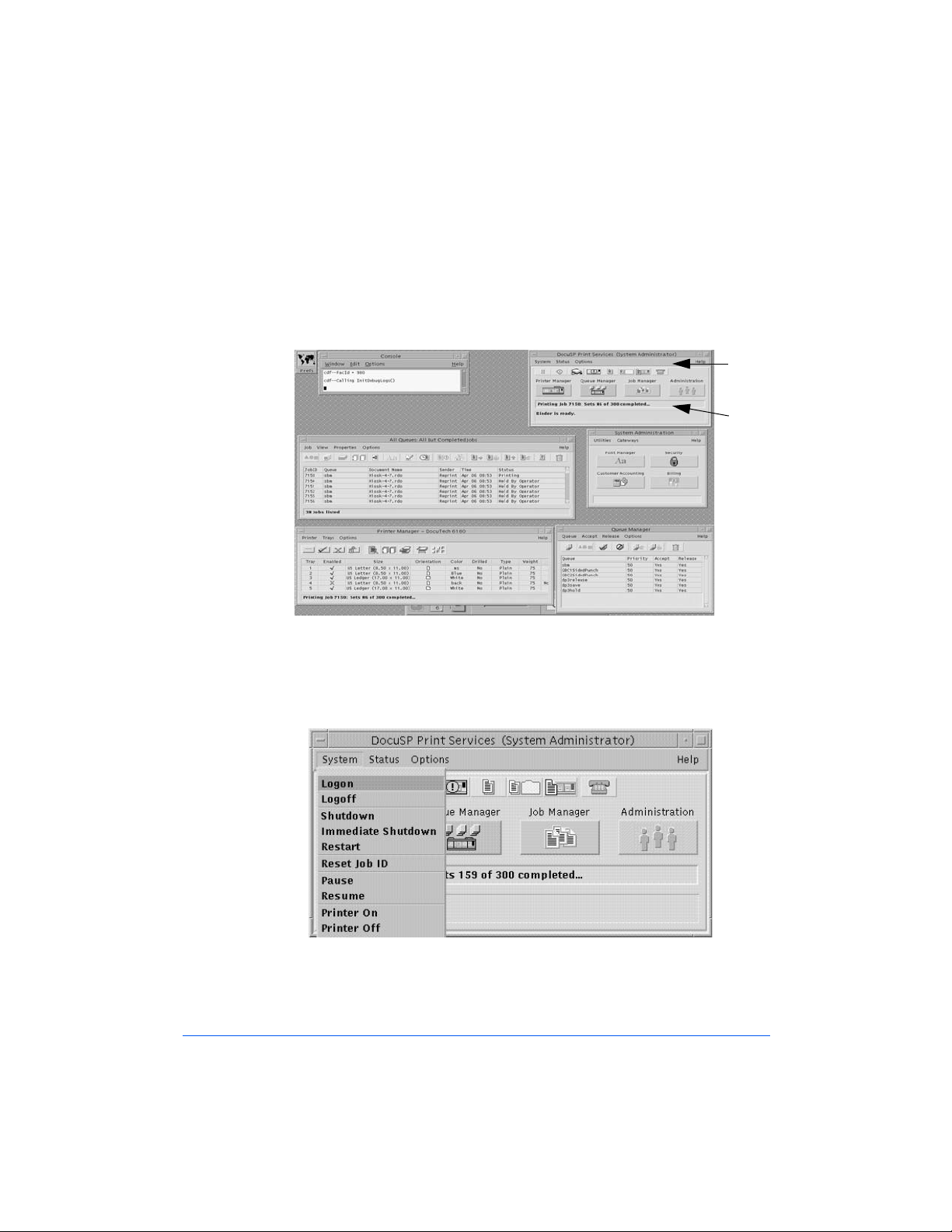
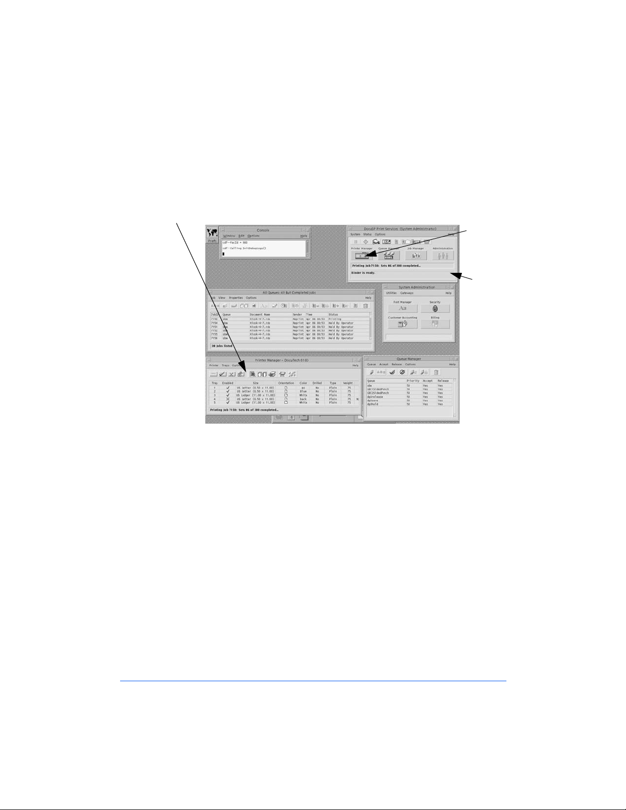
1 Check the logon level in the DocuSP Print Services Screen, as shown
below. If you are already logged in as System Administrator, go to
Step 2. If not, log on as System Administrator, as described below.
Logon
level
DocuSP
Print
Services
Screen
Figure 1-1: 61XX Monitor Screen
a)
Go to the DocuSP Print Services screen, as shown in Figure 1-1.
b) Pull down the System menu and select Logon, as shown in
Figure 1-2.
Figure 1-2: The System Option Menu
1-12 Getting Started
Page 25
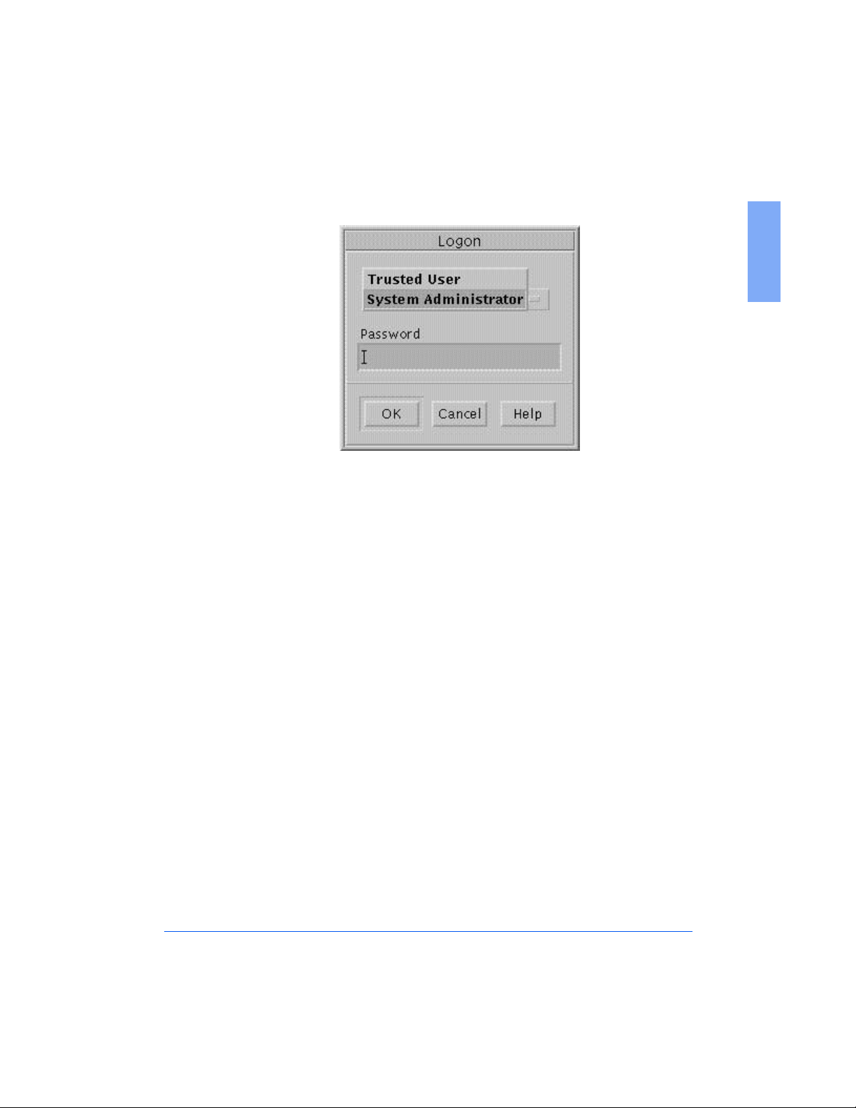
The Logon window will display, as shown in Figure 1-3.
Figure 1-3: The Logon Window
c) Click on Trusted User and then select System Administrator.
d) Type Administ in the password field and then click on OK.
1
Creating 61XX Profiles and Print Queues 1-13
Page 26
61XX Profile Setup
1 From the 61XX Monitor screen, go to the Printer Manager window, as
shown already open in Figure 1-4. If it is not open, go to the DocuSP
Print Services window and click the Printer Manager button.
Printer Manager window
Printer
Manager
button
DocuSP
Print
Services
window
Figure 1-4: 61XX Monitor screen and Printer Manager window
1-14 Getting Started
Page 27
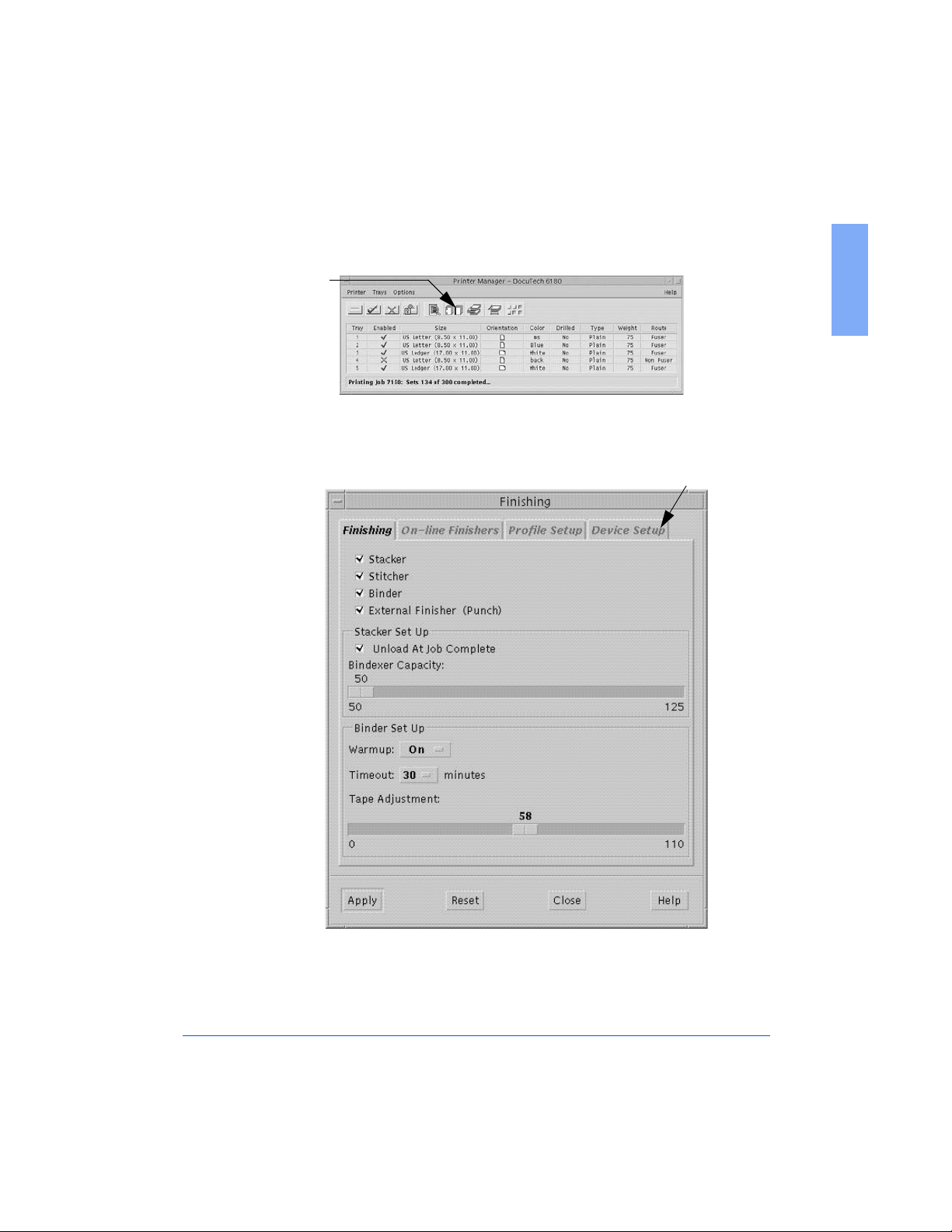
2 Click the Finishing Icon in the Printer Manager Window, as shown in
Figure 1-5.
Finishing Icon
Figure 1-5: The Finishing Icon in Printer Manager
The Finishing Window will display, as shown in Figure 1-6.
1
Device Setup Tab
Figure 1-6: The Device Setup Tab in the Finishing Window
3 Click on the Device Setup Tab, as shown in Figure 1-6.
Creating 61XX Profiles and Print Queues 1-15
Page 28
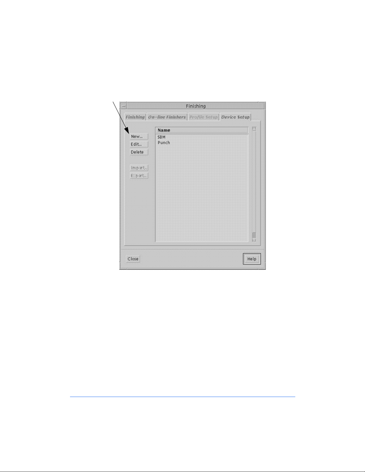
The Device Setup Tab screen will display, as shown in Figure 1-7.
New
Figure 1-7: The Device Setup Tab screen
4 Click on the NEW button, as shown in Figure 1-7.
1-16 Getting Started
Page 29
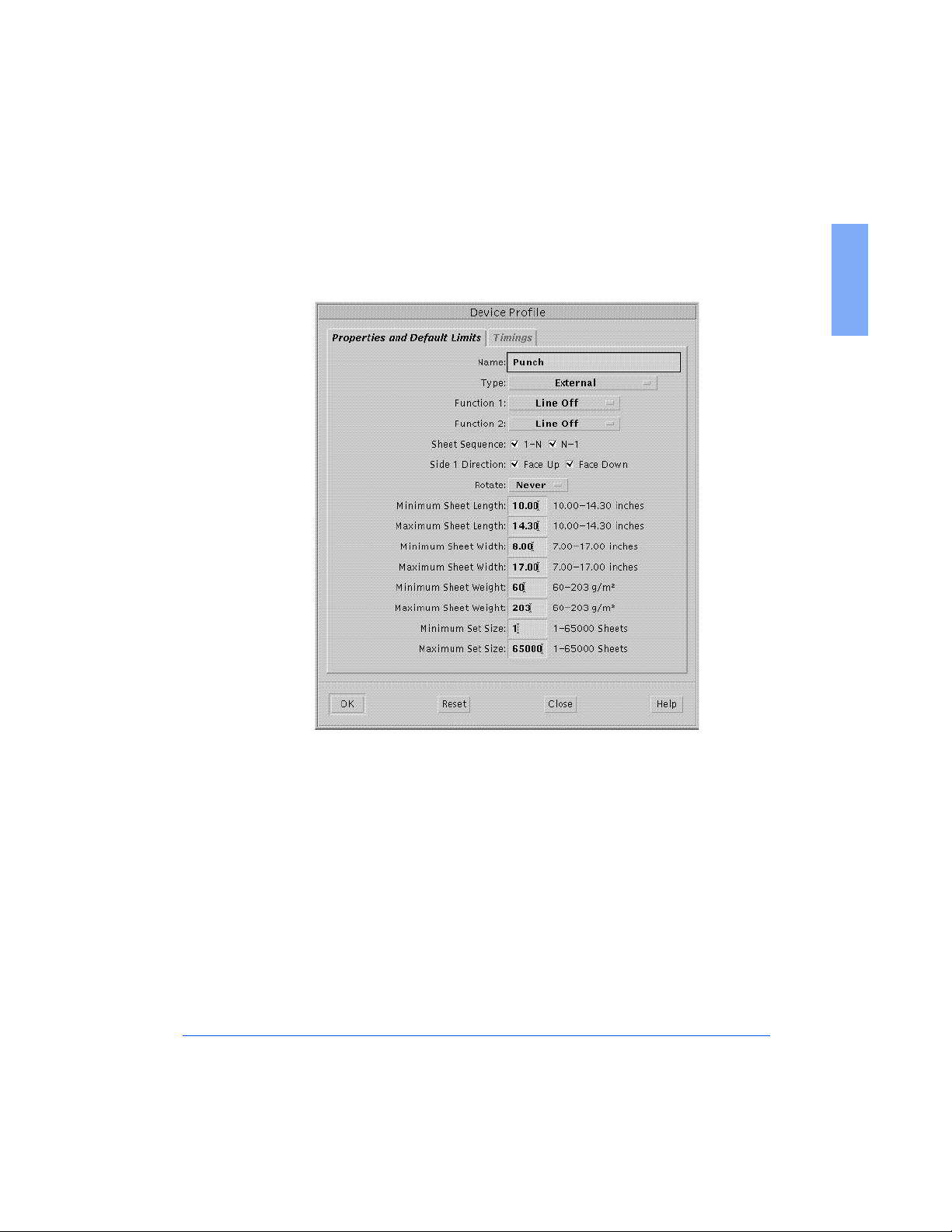
The Device Profile Window will display, with the Properties and
Default Limits tab screen showing, as shown in Figure 1-8.
1
Figure 1-8: The Properties and Default Limits screen
5 With the Device Profile Window and the Properties and Default Limits
screen open, you are ready to begin entering Personality Profile values
for the FusionPunch II and the printer you are using.
Perform the following steps:
a) Go to Appendix A of this User Guide and locate the profile sheets
for the devices you will be setting up.
b) Begin with the sheet for the Properties and Default Limits values.
Creating 61XX Profiles and Print Queues 1-17
Page 30
c) Enter the name and type of the finishing device, for example,
Punch for name and External for type.
d)
Verify that all of the entered values conform to those in the profile
sheet. If they do not, enter the values from the profile sheet.
Note: Do not click OK at this point. Go on to Step 6.
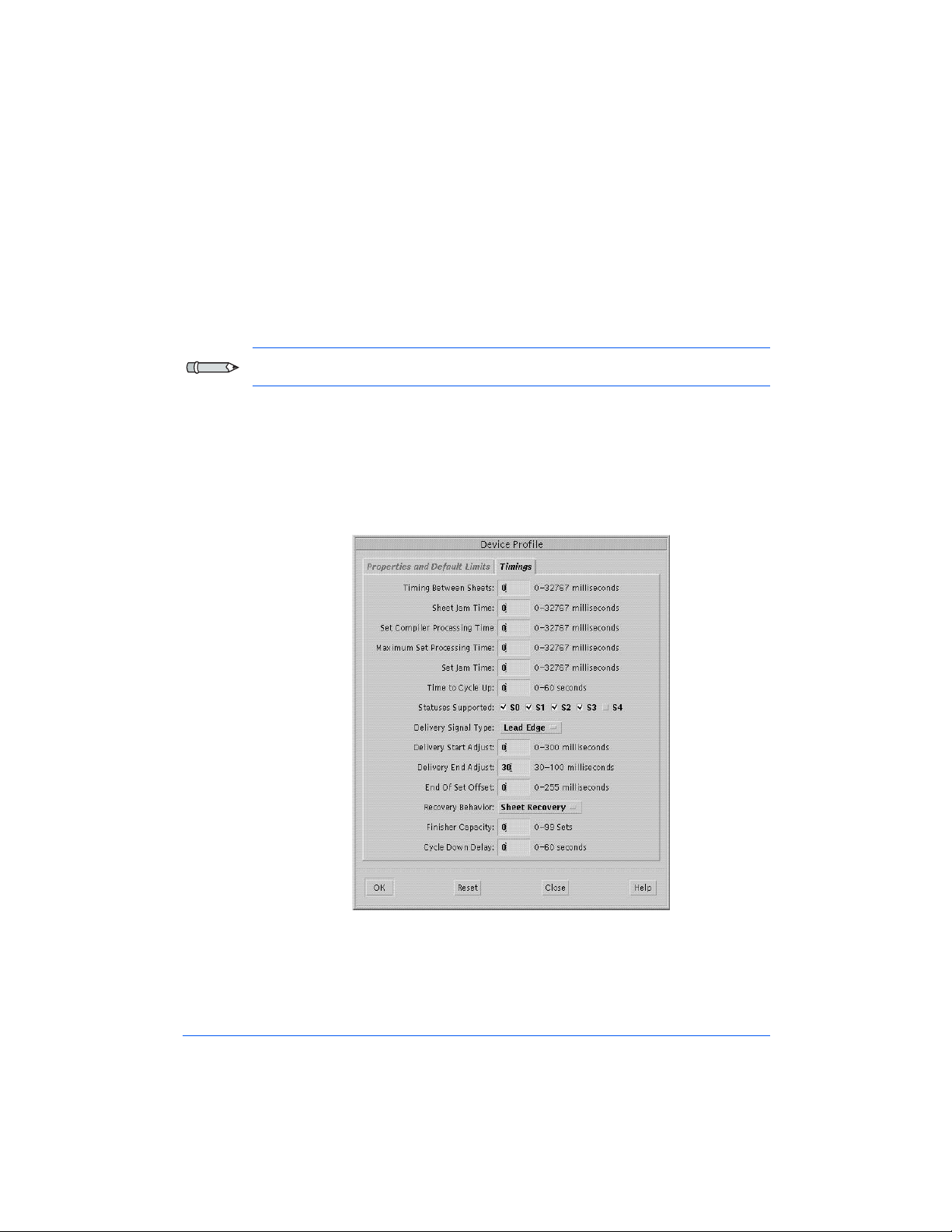
6 Click on the Timings tab in the Device Profile Window.
The Device Profile Window will display the Timings screen, as shown
in Figure 1-9.
Figure 1-9: The Timings screen
1-18 Getting Started
Page 31

7 Perform the following steps:
a) Go back to Appendix A of this User Guide and locate the profile
sheets for the same device as in Step 5, this time using the sheet for
the Timings values.
b) Verify that all of the entered values conform to those in the profile
sheet and click OK.
This will bring you back to the Finishing Window, with the Device
Setup Tab screen displayed.
8 Click on the Profile Setup tab, as shown in Figure 1-10, then click on
the NEW button.
Profile
Setup Tab
New
1
Figure 1-10: The Profile Setup Tab Screen
Creating 61XX Profiles and Print Queues 1-19
Page 32

The Finisher Profile Window, Properties and Limits screen will
display, as shown in Figure 1-11.
Figure 1-11: The Finisher Profile Window, Properties and Limits Screen
9 Perform the following steps:
a) Go to Appendix A in this User Guide and locate the profile sheets
for the same finishing device as in Step 5, but this time, with the
sheet for the Finisher Profile - Properties and Limits values.
b) Ensure that all of the entered values conform to those in the profile
sheet, then click on OK.
1-20 Getting Started
Page 33

The Finishing Window with the Profile Setup screen displays again,
as shown in Figure 1-12.
Note: After entering and/or checking the default values for the
FusionPunch II, you will need to repeat Steps 5 through 9 for each
additional finishing device installed in the system.
On-line button
1
Figure 1-12: The Finishing Window and Profile Setup screen
10 Highlight GBC and click On-Line.
11 Select the On-Line Finishers tab in the Finishing Window.
Creating 61XX Profiles and Print Queues 1-21
Page 34

The On-Line Finishers screen displays, as shown in Figure 1-13.
Enable
Button
Figure 1-13: Finishing Window and On-Line Finishers screen
12 Highlight GBC again and then click the Enable button.
13 Select the Finishing tab in the Finishing Window.
1-22 Getting Started
Page 35

The Finishing screen displays, as shown in Figure 1-14.
External Finisher
Check Box
1
Figure 1-14: Finishing screen in the Finishing Window
14 Ensure that the External Finisher Checkbox is checked and that the
name of the correct device appears in parentheses to the right of
External Finisher, as shown in Figure 1-14.
This completes the Profile setup. Go now to the Print Queue setup
procedure that follows.
Note: If you have more than one finishing device inline with the printer, you
must set up a profile for each. To do so, repeat this profile setup procedure
for each finishing device.
Creating 61XX Profiles and Print Queues 1-23
Page 36

61XX Print Queue Setup
The following procedure is to help the System Administrator set up print
queues for the FusionPunch II and other finishing devices that are inline to
the printer.
Note: One print queue is required for the FusionPunch II and one for each
additional finishing device down the line, such as a Signature Booklet
Maker (SBM).
1 From the 61XX Monitor screen, go to the Queue Manager window, as
shown already open in Figure 1-15. If it is not open, go to the DocuSP
Print Services window and click the Queue Manager button.
Queue
Manager
button
DocuSP
Print
Services
window
Queue
Manager
Window
Figure 1-15: 61XX Monitor screen and Queue Manager window
1-24 Getting Started
Page 37

If the Queue Manager screen is not open, click on the Queue Manager
icon, as shown in Figure 1-16.
Queue
Manager
Icon
Figure 1-16: Queue Manager Icon
2 Pull down the Queue menu from the toolbar and select New, as shown
in Figure 1-17.
New
1
Figure 1-17: The Queue Menu in Queue Manager
Creating 61XX Profiles and Print Queues 1-25
Page 38

The New Queue Setup Window will display, as shown in Figure 1-18.
Queue
Name
Figure 1-18: The New Queue Setup Window
Extended
Options
Fields
Output
3 Go to the Queue Name field and enter the name of the queue to be set
up, as follows:
GBCPunch
n
GBCSE
n
For any other finishing device, enter the name as it appears in its
n
Finisher Profile sheet.
4 Go to the Extended Options field and select Output, as shown in
Figure 1-18.
The Output Window will display, as shown in the information that
follows. This information consists of Print Queue Setup procedures for
the following finishing devices:
GBC Punch Queue Output (for the FusionPunch II)
n
GBC Short Edge Punch Queue Output (for the FusionPunch II and
n
Xerox High Capacity Stacker)
SBM1/SBM2 Queue Output (for the Signature Booklet Maker)
n
1-26 Getting Started
Page 39

GBC Punch Queue Output
a
d
b
c
e
f
g
h
Figure 1-19: The Print Queue Output Window
Refer to Figure 1-19 above and fill in or choose the fields, as specified
in the table below, for a GBC Punch Queue output.
Item Entry
a 2-Sided (Do not check the override option)
1
b System Specified
c Check the Override option
d System Specified
e Check the Override option
f GBC
g Check the Override option
h Click OK, then OK again in new Queue Setup window
Creating 61XX Profiles and Print Queues 1-27
Page 40

GBC Short Edge Punch Queue Output
a
d
b
c
e
f
g
h
Figure 1-20: The Print Queue Output Window
Refer to Figure 1-20 above and fill in or choose the fields, as specified
in the table below, for a GBC Short Edge Punch Queue Output.
Item Entry
a System Specified
b System Specified
c Check the Override option
d System Specified
e Check the Override option
f GBCSE (Note if the GBCSE Personality Profile is not
Online and Enabled, this option will not show up in the
drop down list)
g Check the Override option
h Click OK, then OK again in new Queue Setup window
1-28 Getting Started
Page 41

SBM1/SBM2 Queue Output
a
d
b
c
e
f
g
h
Figure 1-21: The Print Queue Output Window (SBM Setup)
Refer to Figure 1-21 above and fill in or choose the fields, as specified
in the table below, for a SBM Punch Queue output.
Item Entry
a 2-Sided (Do not check the override option)
b System Specified
1
c Check the Override option
d System Specified
e Check the Override option
f Same as the name of the Finisher Profile for the
SBM1/SBM2
g Check the Override option
h Click OK, then OK again in new Queue Setup window
Creating 61XX Profiles and Print Queues 1-29
Page 42

This completes the Print Queue setup and Chapter 1 of this User Guide.
Go now to Chapter 2 - General Procedures, to become familiar with
basic operator-level mechanical adjustments and operation of the
FusionPunch II.
1-30 Getting Started
Page 43

General Procedures
Changing Die Sets
Removing and Replacing Die Pins
Centering the Punch
Chapter 2
2
Setting the Side Guide
Setting Backgauge for Punch Depth from End of
Page
Starting a Job
Punching and Stacking
Bypassing to a Downstream device
Using the Stacker / Stackers
Page 44

2-2 General Procedures
Page 45

Changing Die Sets
WARNING: Switch OFF (O) the main power switch before beginning this
procedure.
1 Open the Right Punch Door, as shown in Figure 2-1.
2 Open the Punch Cover, as shown in Figure 2-1.
Punch Cover
Right Punch
Door
2
Figure 2-1: Opening the Punch Door and Cover
Changing Die Sets 2-3
Page 46

3 Open the Sheet Eject Strap assembly, as shown in Figure 2-2.
4 Release the Punch Arm retaining levers down and to the side, as shown
in Figure 2-2.
Sheet Eject Strap
Assembly
Punch Arm
Retaining
Levers
Die Lock
Knob
Figure 2-2: Unlocking the Die Assembly
5 Unlock the Die: turn the Die Lock knob clockwise until a "click" is felt,
as shown in Figure 2-2. Do not turn past that point or you will lock the
Die again.
2-4 General Procedures
Page 47

6 Grasp the base of the Die and lift straight up, as shown in Figure 2-3.
Figure 2-3: Removing and replacing the Die Assembly
7 To replace the Die, repeat Steps 1 through 6 in reverse order.
Note: The Die assembly is keyed and will reinstall only one way.
2
Changing Die Sets 2-5
Page 48

Removing and Replacing Die Pins
1 To remove and replace individual die pins, slide the Pressure Bar
release levers to the side and lift the Pressure Bar off of the Die, as
shown in Figure 2-4.
You may now remove and replace individual die pins.
Pressure Bar
Pressure Bar
Release
Die Pins
Die Base
Figure 2-4: Accessing the Die Pins
2 Reverse this procedure to reinstall the Punch Arm.
Lift Pressure
Bar in this
direction
2-6 General Procedures
Page 49

Centering the Punch
The purpose of this procedure is to center the punched hole set on the paper.
1 Set up the FusionPunch II in the following modes and destination;
"Offline / Punch / Stack 1" (or Stack 2).
2
Ensure that the Stacker Tray is in the TOP position. If it is not, press the
RAISE/LOWER STACKER 1 or 2 button either once or twice
until the Stacker moves up to its TOP position. The Punch will not start
with the Stacker Tray down.
3 Press START .
4 Into the Single Sheet Feeder, feed a sheet of paper of the size required
for the job.
5 Press the STOP/RESET button.
6 Press the RAISE/LOWER STACKER 1 or 2 button to lower the
Stacker.
7 Open the Stacker Door and remove the punched sheet of paper.
8 Check the centering of the punched holes, as shown in Figure 2-5.
Punch is
centered
2
Figure 2-5: Checking the Centering of the Punched Holes
Centering the Punch 2-7
Page 50

9 If the holes are centered, go on to Setting the Side Guide. If the holes
are not centered, go on to Step 10 to adjust the Punch.
10
Open the Right Punch Door.
11 Loosen the Locking Wing Nut, as shown in Figure 2-6.
12 Use the Edge Guide Adjustment Knob to make small (1/8 to 1/4-turn)
adjustments, as shown in Figure 2-6. Test after each adjustment until
the punched hole sets are centered.
Locking Wing Nut
Edge Guide
Adjustment Knob
Figure 2-6: Edge Guide Adjustment
13 Tighten the Locking Wing Nut after you have completed the
adjustments.
2-8 General Procedures
Page 51

Setting the Side Guide
The purpose of this procedure is to ensure that each sheet of paper maintains
registration as it passes through the FusionPunch II.
Note: Use tab stock or cover stock when performing these procedures.
1 Press the STOP/RESET button.
2 Open the Punch Cover.
3 Open the Document Transport Ball Track assembly, as shown in
Figure 2-7.
4 Open the Sheet Eject assembly, as shown in Figure 2-7.
Document
Transport Ball
Track Assembly
Sheet Eject
Strap Assembly
Figure 2-7: Preparing to Adjust the Side Guide
2
Setting the Side Guide 2-9
Page 52

5 Slide a sheet of tab stock or cover stock partially through the Die.
6 Ensure that the stock is against the Document Transport Guide Rail, as
shown in Figure 2-8. If the stock is straight against the Document
Transport Guide Rail and as close as possible to the Side Guide without
actually touching it, go on to Setting the Backgauge. If the Side Guide
is not as close as possible to the stock without touching it, go on to
Step 7 to adjust the Side Guide.
Side Guide
Retaining Screw
Infeed Guide
(Teflon® Plastic
Piece)
Cover Stock
Figure 2-8: Adjusting the Side Guide
Side Guide
Document
Transport
Guide Rail
7 If punching the 11" edge of the sheet, loosen the Side Guide Retaining
Screw. If punching the 8.5" edge of the sheet, add the additional Short
Edge Side Guide to the Sheet Eject Strap assembly with the adjustment
screws finger tight. Remove the stock and close the Sheet Eject Strap
assembly. Now, slide the stock under the Sheet Eject Straps and
partially through the Die again.
Note: When using the existing 11" Side Guide, ensure that the Side Guide
is under the Infeed Guide (Figure 2-8) before continuing.
Teflon® is a registered trademark of E.I. du Pont de Nemours and Company.
2-10 General Procedures
Page 53

8 Adjust the Side Guide so that it is as close to the stock as possible
without actually touching the stock.
9
Tighten the Side Guide Retaining Screw/s.
10 When you have completed this procedure, close the Sheet Eject Strap
assembly, Document Transport Ball Track assembly, and the Punch
Cover if they are not already closed.
2
Setting the Side Guide 2-11
Page 54

Setting the Backgauge
The purpose of this procedure is to ensure that the margin between the
leading edge of the copy and the punched holes is correct.
1 If your die set is anything other than a GBC Cerlox die set, turn the
Backgauge Adjustment Knob clockwise continuously until it stops. If
your die set is a GBC Cerlox die set, go to Step 2.
2 Check the margin between the leading edge and the punched holes of
copies that have been run through the Punch, or, from paper you have
run through the Manual Feed Tray. If the margin is correct, go to
Starting a Job in this chapter to familiarize yourself with the operation
of the FusionPunch II. If the margin is not correct, go to Step 3 to
adjust the Backgauge.
Margin
Backgauge
Adjustment Knob
Figure 2-9: Setting the Backgauge Adjustment
2-12 General Procedures
Page 55

3 Open the Right Punch Door.
4 Use the Backgauge Adjustment Knob to correct the margin, as shown in
Figure 2-9. Adjust as follows:
To increase the margin between the leading edge of the copy and
n
the punched holes, turn the Backgauge Adjustment Knob
counterclockwise.
To decrease the margin, turn the adjustment knob clockwise.
n
5 Turn the Backgauge Adjustment Knob one click at a time and check the
margin at each position. Use the Single Sheet Feeder to run test paper
through the Punch. To do this:
a) Set up the FusionPunch II in the following modes and destination;
"Offline / Punch / Stack 1" (or Stack 2).
b) Ensure that the Stacker Tray is in the TOP position. If it is not,
press the RAISE/LOWER STACKER 1 or 2 button either
once or twice until the Stacker moves up to its TOP position. The
Punch will not start with the Stacker Tray down.
c) Press START .
d) Into the Single Sheet Feeder, feed a sheet of paper of the size
required for the job.
e) Press the STOP/RESET button.
f) Press the RAISE/LOWER STACKER 1 or 2 button to
lower the Stacker.
g) Open the Stacker Door and remove the punched sheet of paper.
h) Close the Stacker Door and press the RAISE/LOWER STACKER
1 or 2 button to raise the tray.
2
6 Repeat Steps 4 and 5 until the margin is correct.
Setting the Backgauge 2-13
Page 56

Starting a Job
Punching and Stacking
For punching and stacking the 11" edge in the GBC Stacker without a
n
Bypass installed, follow the procedure below.
For punching and stacking the 11" edge in the Xerox High Capacity
n
Stacker, go to Starting a Job for Bypassing to a Downstream device
(Page 2-20.)
For punching and stacking the 8.5" edge, go to Starting a Job for
n
Bypassing to a Dowstream device (Page 2-20.)
To prepare for starting a printing job and sending it to the FusionPunch II,
perform the following procedures.
1 Set up the FusionPunch II according to the job requirements (For
FusionPunch II setup, refer to the Getting Started section, On-line /
Off-line).
2 From the DocuSP Print Services screen, open the Printer Manager
window and click on the Finishing Icon.
Figure 2-10: The Finishing Window
2-14 General Procedures
Page 57

The Finishing Window will display, defaulted to the Finishing tab.
3 Click on the On-line Finishers tab. The window will display as shown
below.
On-line
Finishers
Ta b
2
Figure 2-11: On-line Finishers tab
4 Verify that the GBC FusionPunch II profile is Enabled. If this profile
is not visible in this window, go to step 8. If this profile is visible but not
Enabled (green check-mark in the Enabled column), highlight the
profile and click Enable and then click Close.
Starting a Job 2-15
Page 58

5 Go to the Job Manager window and highlight the job to run. Click the
Move Icon.
Figure 2-12: Job Manager window
Move Icon
6 Highlight the GBC Punch Queue and then click Apply.
Figure 2-13: GBC Punch Queue window
2-16 General Procedures
Page 59
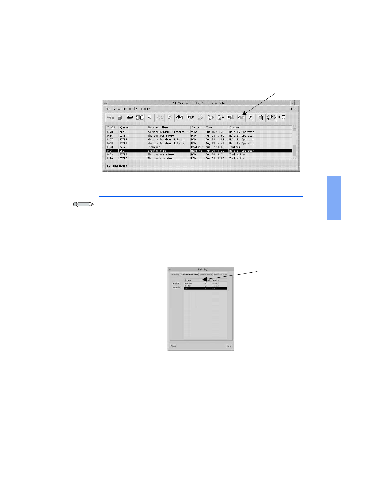
7 Click the Release Icon to start running the job.
Figure 2-14: Release Icon in the Job Manager window
Release Icon
Note: When you release a new job, sets from the job before may be left in
the Stacker / Stackers.
8 Highlight any External Profile shown in the On-line Finishers tab
window and click Disable. The green check-mark in the Enabled
column of the highlighted profile should now have switched to a red X
as shown in the figure below.
Enabled column
Figure 2-15: On-line Finishers tab
2
Starting a Job 2-17
Page 60

9 Click the Profile Setup tab as shown in the figure below. Highlight any
enabled profile (not the GBC FusionPunch II profile) and then click
Off-line. Now highlight the GBC FusionPunch II profile and click
On-line. The GBC FusionPunch II profile should now have a green
check-mark in the On-line column as shown in the figure below.
Profile
Setup Tab
Figure 2-16: Profile Setup tab
2-18 General Procedures
Page 61

10 Go back to the On-line Finishers tab and highlite the GBC
FusionPunch II profile, then click Enable. The GBC FusionPunch II
profile should now have a green check-mark in the Enabled column.
Enable
Close
2
Figure 2-17: On-line Finishers tab
11 Click Close to close this window. Now go back and follow steps 4 - 7.
Starting a Job 2-19
Page 62

Starting a Job
Bypassing to a Downstream device
To prepare for starting a printing job and sending it to the Bypass
Destination, as well as the Downstream device, perform the following
procedures.
1 Set up the FusionPunch II in the Bypass Destination, as well as the
correct Punch mode (For FusionPunch II setup, refer to the Getting
Started section, On-line / Off-line). Once the FusionPunch II is setup
for the application, go to the Downstream device and enable it for
On-line operation.
2 From the DocuSP Print Services screen, open the Printer Manager
window and click on the Finishing Icon.
The Finishing Window will display, defaulted to the Finishing tab, as
shown below.
Figure 2-18: The Finishing Window
2-20 General Procedures
Page 63
3 Click on the On-line Finishers tab. The window will display as shown
below.
On-line
Finishers
Ta b
2
Figure 2-19: On-line Finishers tab
4 Verify that the profile for the Downstream device to be used is
Enabled.
l
For punching and stacking the 11" edge in the Xerox High Capacity
Stacker, ensure the HCS profile is Enabled.
l
For punching and stacking the 8.5" edge, ensure the GBCSE
profile is Enabled.
l
For all other applications, ensure the profile that associates with the
Downstream device to be run is Enabled.
(In the figure above is an example of a job being sent to a Signature
Booklet Maker.) If this profile is not visible in this window,
go to step 8. If this profile is visible but not Enabled (green check-mark
in the Enabled column), highlight the profile and click Enable and then
click Close.
Starting a Job 2-21
Page 64

5 Go to the Job Manager window and highlight the job to run. Click the
Move Icon.
Figure 2-20: Job Manager window
Move Icon
6 Highlight the appropriate Queue for your job (in the figure below is an
example of a SBM Queue) and then click Apply.
Figure 2-21: SBM Queue window
2-22 General Procedures
Page 65

7 Click the Release Icon to start running the job.
Figure 2-22: Release Icon in the Job Manager window
Release Icon
8 Highlight any External Profile shown in the On-line Finishers tab
window and click Disable. The green check-mark in the Enabled
column of the highlighted profile should now have switched to a red X
as shown in the figure below.
Enabled
column
2
Figure 2-23: On-line Finishers tab
Starting a Job 2-23
Page 66

9 Click the Profile Setup tab as shown in the figure below. Highlight any
enabled profile (not the SBM profile) and then click Off-line. Now
highlight the SBM profile and click On-line. The SBM profile should
now have a green check-mark in the On-line column as shown in the
figure below.
Profile Setup
Ta b
Figure 2-24: Profile Setup tab
2-24 General Procedures
Page 67

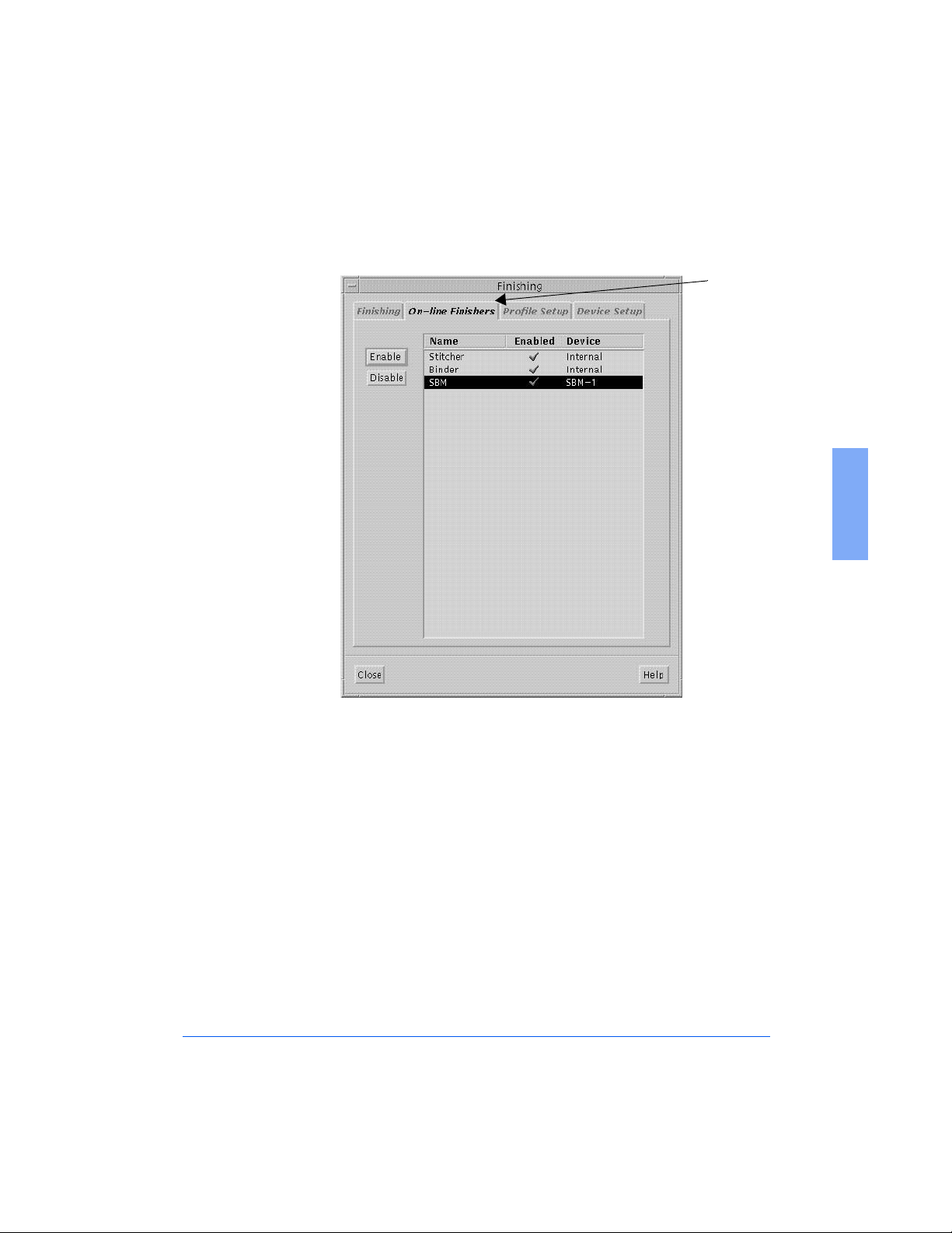
10 Go back to the On-line Finishers tab and highlight the SBM profile,
then click Enable. The SBM profile should now have a green checkmark in the Enabled column.
Enable
Close
2
Figure 2-25: On-line Finishers tab
11 Click Close to close this window. Now go back and follow steps 4 - 7.
Starting a Job 2-25
Page 68

Using the GBC Stacker
The GBC Stacker is inline with the FusionPunch II and interfaces
electronically and mechanically with the FusionPunch II. The Stacker will
start up and shut down automatically with the Punch, under control of the
Printer.
The Stacker requires minimal operator intervention, with the exception of
unloading the Stacker Tray. Although the internal Stacker Tray has an
extension that is adjustable, you will seldom have to change this adjustment,
except in the case of job runs with unique paper sizes. See Figure 2- 26
below for locations of Stacker components.
Stacker Door
Stacker Tray
Figure 2-26: The GBC Stacker with Front Door open
2-26 General Procedures
Page 69

To lower the Stacker Tray for unloading, go to the FusionPunch II Control
Panel and do the following:
1
If in Cycle Up mode:
and only one stacker is installed, wait for the FusionPunch II and
n
the host printer to cycle down. GBC Fusion Full Stop will be
displayed in the LCD Display Screen when the machines have
cycled down.
and the system is equipped with a Second Offset Stacker, you will
n
not have to wait for the the punch and the printer to cycle down. By
setting the destination to Stack 1 or Stack 2 the FusionPunch II
will automatically switch between the stackers as long as the next
stacker’s tray is in the up position.
2 Press the Raise/Lower Stacker #1 button to lower the tray of the
first (#1) Stacker in the system.
Press the Raise/Lower Stacker #2 button to lower the tray of the
second stacker in the system (if a second Stacker is installed).
3 Open the Stacker Door and remove the punched copy.
2
4 Close the Stacker Door.
5 Press the Raise/Lower Stacker button(s) to raise the Stacker tray
(or trays) back up to the top position. The Punch will not start with the
Stacker tray(s) down. The following applies to Stackers:
If a single Stacker is used and its tray is down, the Punch Control
n
Panel will display a message telling you to empty the Stacker. The
Punch will not start until the tray is up.
If more than one Stacker is employed in the system, at least one of
n
the Stackers’ trays must be up to start the Punch. However, when
that Stacker fills up, the Punch will not switch to the other Stacker
if its tray is down. Instead, it will stop the Printer and display a
message telling you to empty the Stacker.
Using the GBC Stacker 2-27
Page 70

2-28 General Procedures
Page 71

Clearing Jams
Error Messages
from the Printer
Chapter 3
Troubleshooting
from the FusionPunch II
from downstream devices
3
Page 72

3-2 Troubleshooting
Page 73

Clearing Jams
A good rule for clearing jams is to follow the paper path through the Punch
and Bypass Stacker, from left to right. The jam clearing procedures are as
follows:
1 Press the Stop/Reset button on the Punch Control Panel.
2 Open both Top Covers on the Punch, as shown in Figure 3-1.
3 Open (lift) the Input Ball Tracks, as shown in Figure 3-1, and clear any
paper that may be jammed in that area. Also, check the printer Finisher
and output tray for any paper jams.
To p Co ve r s
Input Ball
Tracks
Assembly
Figure 3-1: The Top Covers and Input Ball Tracks
Clearing Jams 3-3
3
Page 74

4 Open (lift) the Input Guide Roller assembly, the Document Transport
Ball Track assembly and the Sheet Eject Strap assembly, as shown in
Figure 3-2 and clear any paper that may be jammed in that area.
Input Guide
Roller
Sheet Eject
Strap
Document
Transport Ball
Track
Figure 3-2: The Internal Paper Path Components
Output Guide
Roller
5 Remove the Output Guide Roller assembly, as shown in Figure 3-2 and
clear any paper that may be jammed in that area.
6 Reinstall the Output Guide Roller assembly and ensure that all
assemblies are locked down. Then, close the Top Covers.
7 Open the Bypass Stacker Top Cover and clear any paper that might be
jammed in that area.
8 If the FusionPunch II is set up in Cycle Up mode, press the S t o p / R e se t
button and the job will restart automatically.
9 If the FusionPunch II is set up in Online mode, press the S to p/ Re se t
button to clear the error message and then press Start .
3-4 Troubleshooting
Page 75

Error Messages
From the Printer
The following is a listing of Punch-related error messages that could appear
on the Host Printer display screen. Also included are a description of the
possible causes and the resolution for each problem.
Error Message Possible Cause Resolution
DocuTech 135:
Clear External Finisher
to run jobs to the
Bypass Transport/
External Finisher not
ready.
DocuTech 135:
External Finisher Full.
DocuTech 61XX:
Clear External Finisher
to run jobs to the
Bypass Transport or
External Finisher not
ready.
1. The current job has
a fault and must be
reset.
2. The FusionPunch II
is not Online.
The Punch has filled
the Stacker and is
waiting to be
emptied.
The FusionPunch II
is not Online.
1. Click on the Printer icon.
If there is a reset option,
select Reset .
2. Press Stop/Reset
at the Punch and then press
"ONLINE/OFFLINE".
Ensure that the Punch is in
the Online mode and then
press Start .
Unload the Stacker and
then restart the Punch
Online.
Press Stop/Reset
at the Punch and then press
"ONLINE/OFFLINE".
Ensure that the Punch is in
the Online mode and then
3
press Start .
Figure 3-3: Printer-Generated Error Messages
Error Messages 3-5
Page 76
Error Message Possible Cause Resolution
DocuTech 61XX:
External Finisher Full
Xerox 4xxx Printer:
External Finisher not
ready.
Xerox 4xxx Printer:
External Finisher Full.
Xerox 4xxx Printer
does not recognize the
External Finisher.
The Punch has filled
the Stacker and is
waiting to be
emptied.
The FusionPunch II
is not Online.
The Stacker has
filled and is waiting
to be emptied.
1. The Profile has not
been set up
correctly.
2. The Profile has not
been loaded into the
Printer correctly or
has not been loaded
at all.
Unload the Stacker and
then restart the Punch
Online.
Press Stop/Reset
at the Punch and then press
"ONLINE/OFFLINE".
Ensure that the Punch is in
Online Mode, then press
Start .
Unload the Stacker and
then restart the Punch
Online.
1. Check the Profile at the
Printer to ensure proper
Host Enablement. Call
your System Administrator
and refer to the setup
procedures in Appendix A
of this User Guide.
2. Call the Xerox Service
Representative to verify
proper Host Enablement.
Xerox 4xxx / DT 135 /
61XX Printer
Jam in area 20 and
A jam has occurred
in the
FusionPunch II.
1. Discard any sheets that
have not been completely
delivered to the Stacker.
External Finisher or
External Finisher jam.
2. Press Stop/Reset
to clear error message.
Follow printer jam
clearance procedure and
resume the job.
Figure 3-3: Printer-Generated Error Messages
3-6 Troubleshooting
Page 77

Error Messages
From the FusionPunch II
The following is a listing of Punch-related error messages that could appear
on the FusionPunch II Control Panel Display screen. Also included are a
description of the possible causes and the resolution for each problem.
Error Message Possible Cause Resolution
Punch Covers Open The Interlock Switch
under one or both of
the Punch covers is not
actuated.
Punch Left Door open/
Punch Mid Door open/
Punch Right Door
open
Stacker Cover open The Interlock Switch
Stacker Door open The Interlock Switch
The Interlock Switch
behind the Punch Door
that corresponds to the
error message is not
actuated.
under the Stacker’s
Top Cover is not
actuated.
behind the Stacker
Door is not actuated.
Open and close both Punch
covers and ensure that they
are securely closed. If the
problem persists, call your
GBC or Xerox Service
Representative.
Open and close the
appropriate door,
corresponding to the error
message, and ensure that it is
securely closed. If the
problem persists, call your
GBC or Xerox Service
Representative.
Open and close the Stacker’s
Top Cover and ensure that it
is securely closed. If the
problem persists, call your
GBC or Xerox Service
Representative.
Open and close the Stacker
Door and ensure that it is
securely closed. If the
problem persists, call your
GBC or Xerox Service
Representative.
3
Figure 3-4: Punch-Generated Error Messages
Error Messages 3-7
Page 78
Error Message Possible Cause Resolution
Jam Entrance Sensor 1. There is a sheet of
paper blocking the
Entrance Sensor
(first sensor from
the left side of the
machine).
2. The Entrance Sensor
and/or its Reflector
may be dirty.
3. The Side Guide may
be adjusted too tight
for the paper, cover
stock, or tab stock.
1. Lift up the Input Track
Ball assembly and remove
the paper.
2. Clean the Entrance Sensor
and reflector, using
Isopropyl alcohol and a
clean, lint-free cloth. If the
problem persists, call your
GBC or Xerox Service
Representative.
3. Ensure that the Side Guide
is not too tight. Perform
the adjustment in Chapter
2 (Setting the Side Guide).
If the problem persists, call
your GBC or Xerox
Service Representative.
4. Press Stop/Reset
button to clear error
message. Follow printer
jam clearance procedure
and resume the job.
Figure 3-4: Punch-Generated Error Messages
3-8 Troubleshooting
Page 79

Error Message Possible Cause Resolution
Jam Document
Transport Sensor 1
1. There is a sheet of
paper blocking the
first Document
Transport Sensor
(second sensor from
the left).
2. The Document
Transport Sensor 1
and/or its Reflector
may be dirty.
3. The Side Guide may
be adjusted too tight
for the paper, cover
stock, or tab stock.
1. Lift up the Document
Transport Track Ball
assembly and remove the
paper.
2. Clean the Document
Transport Sensor 1 and
reflector, using Isopropyl
alcohol and a clean, lintfree cloth. If the problem
persists, call your GBC or
Xerox Service
Representative.
3. Ensure that the Side Guide
is not too tight. Perform
the adjustment in Chapter
2 (Setting the Side Guide).
If the problem persists, call
your GBC or Xerox
Service Representative.
4. Press Stop/Reset
button to clear error
message. Follow printer
jam clearance procedure
and resume the job.
3
Figure 3-4: Punch-Generated Error Messages
Error Messages 3-9
Page 80

Error Message Possible Cause Resolution
Jam Document
Transport Sensor 2
1. There is a sheet of
paper blocking the
second Document
Transport Sensor
(third sensor from
the left).
2. The Document
Transport Sensor 2
and/or its Reflector
may be dirty.
3. The Side Guide may
be adjusted too tight
for the paper, cover
stock, or tab stock.
1. Lift up the Document
Transport Track Ball
assembly and remove the
paper.
2. Clean the Document
Transport Sensor 2 and
reflector, using Isopropyl
alcohol and a clean, lintfree cloth. If the problem
persists, call your GBC or
Xerox Service
Representative.
3. Ensure that the Side Guide
is not too tight. Perform
the adjustment in Chapter
2 (Setting the Side Guide).
If the problem persists, call
your GBC or Xerox
Service Representative.
4. Press Stop/Reset
button to clear error
message. Follow printer
jam clearance procedure
and resume the job.
Figure 3-4: Punch-Generated Error Messages
3-10 Troubleshooting
Page 81

Error Message Possible Cause Resolution
Jam Punch Sensor 1. There is a sheet of
paper blocking the
Punch Sensor
(fourth sensor from
the left).
2. The Punch Sensor
and/or its Reflector
may be dirty.
3. The Side Guide may
be adjusted too tight
for the paper, cover
stock, or tab stock.
Jam Punch Exit Sensor 1. There is a sheet of
paper blocking the
Punch Exit Sensor at
the Stacker’s input.
2. The Punch Exit
Sensor and/or its
Reflector may be
dirty.
1. Lift up the Sheet Eject
Strap assembly and
remove the paper.
2. Clean the Punch Sensor
and reflector, using
Isopropyl alcohol and a
clean, lint-free cloth.
3. Ensure that the Side Guide
is not too tight. Perform
the adjustment in Chapter
2 (Setting the Side Guide).
If the problem persists, call
your GBC or Xerox
Service Representative.
4. Press Stop/Reset
button to clear error
message. Follow printer
jam clearance procedure
and resume the job.
1. Lift up the Stacker Top
Cover and remove the
paper.
2. Clean the Punch Exit
Sensor and reflector, using
Isopropyl alcohol and a
clean, lint-free cloth. If the
problem persists, call your
GBC or Xerox Service
Representative.
3
3. Press S t o p / R e s e t
button to clear error
message. Follow printer
jam clearance procedure
and resume the job.
Figure 3-4: Punch-Generated Error Messages
Error Messages 3-11
Page 82

Error Message Possible Cause Resolution
Please Empty Stacker 1. The Stacker is full.
2. The Stacker Tray
was left in the
DOWN position.
Please Check
Chip Box
Each time the
FusionPunch II is
turned ON this
message will appear. It
will also appear after
100,000 completed
punches.
1. Press the appropriate
Raise/Lower Stacker
button (No. 1 or No.
2) to lower the Stacker
Tray. Then, unload the
Stacker.
2. Press the appropriate
Raise/Lower Stacker
button (No. 1 or No.
2) to raise the Tray to its
Home position. If the
problem persists, call your
GBC or Xerox Service
Representative.
Open the Punch Right Door,
and leave it open for at least
5 seconds before closing it.
The total count will not be
affected by opening the
Punch Right Door.
Stacker Upper
Switch ??
The Stacker’s Upper
Switch did not release
during an emptying
Lower and raise the Stacker
Tray several times, using the
appropriate Raise/Lower
operation.
Stacker button (No. 1
or No. 2). Then, press the
Stop/Reset button.
If the problem persists, call
your GBC or Xerox Service
Representative.
Figure 3-4: Punch-Generated Error Messages
3-12 Troubleshooting
Page 83

Error Messages
From downstream devices
The following is a listing of error messages that could appear on the
FusionPunch II Control Panel Display screen genereted by a downstream
device. Also included are a description of the possible causes and the
resolution for each problem.
Note:
These messages will only be displayed when the FusionPunch II is
set up in Bypass mode. If all messages are displayed one after the other,
make sure that the downstream device is turned on and that the
communications cable (DFA Cable) is properly connected.
Error Message Possible Cause Resolution
Next Device
Not Ready
Next Device Faulted The downstream
Next Device Full The downstream
The downstream
device from the
FusionPunch II is not
ready to receive paper.
device from the
FusionPunch II is in a
Fault condition and is
is not ready to receive
paper.
device from the
FusionPunch II is in a
Full condition and is
not ready to receive
paper.
Check the downstream
device for further
information.
Check the downstream
device for further
information and faultresolutions.
Check the downstream
device for further
information.
3
Figure 3-5: Downstream device - Generated Error Messages
Error Messages 3-13
Page 84

3-14 Troubleshooting
Page 85

Maintenance
Cleaning the FusionPunch II
Chapter 4
4
Page 86

4-2 Maintenance
Page 87

Cleaning the FusionPunch II
Your FusionPunch II is designed as a high-speed, inline production Punch
that requires only a minimal amount of attention from the operator. But,
because it is a production machine and because it handles and punches
paper, we recommend a light cleaning of the paper path components
periodically, to remove accumulations of paper dust, paper chips and toner.
GBC recommends the following operator maintenance practices.
When to Clean
The following is based on a printing house that operates one to three shifts a
day.
Usage Cleaning Intervals
Heavy usage (continuous - 8 hours per shift) after each shift
Medium Usage (intermittent - 4 hours per shift) after every 2 shifts
Light usage (intermittent - 2 to 3 hours per shift) after every 3 shifts
In effect, the FusionPunch II should be cleaned after every 8 continuous
hours of operation.
Note: In a very busy shop with significant paper dust in the air, the
FusionPunch II may have to be cleaned more frequently - for example, after
every 6 continuous hours of operation.
Cleaning the FusionPunch II 4-3
4
Page 88

What to Use
GBC recommends using only 90% Isopropyl alcohol and a clean, lint-free
cloth. 90% Isopropyl alcohol is available from any local pharmacy.
CAUTION: To prevent possible damage to the machine, use only 90%
Isopropyl alcohol. Do not use film remover or any other type of cleaning
solvent.
What to Clean
A good rule for cleaning that is easy to remember is to follow the paper path
through the Punch and Bypass Stacker, from left to right. The cleaning
procedures are as follows:
WARNING: Switch OFF (O) the Main Power Switch before performing this
procedure.
4-4 Maintenance
Page 89

Cleaning the Punch
1 Open the Top Covers on the FusionPunch II, as shown in Figure 4-1.
2 Open (lift) the Input Ball Tracks, as shown in Figure 4-1. Clean the
green belt under the three ball tracks, the Sensor Reflector and the
Sensor (under the hole in the base plate) with Isopropyl alcohol and a
clean, lint-free cloth. Check also for accumulations of paper dust or
toner under the base plate.
Top Covers
Input Ball
Tracks
Assembly
Figure 4-1: The Top Covers and Input Ball Tracks
Cleaning the Punch 4-5
4
Page 90

3 Open (lift) the Input Guide Roller assembly, as shown in Figure 4-2.
Clean the rollers with Isopropyl alcohol and a clean lint-free cloth.
Check also for accumulations of paper dust or toner on the base plate.
4 Open (lift) the Document Transport Ball Track assembly, as shown in
Figure 4-2. Clean the green belt under the ball track, both Sensor
Reflectors and both Sensors (under the holes in the base plate) with
Isopropyl alcohol and a clean lint-free cloth. Check also for
accumulations of paper dust or toner on the base plate.
Input Guide
Roller
Sheet Eject
Strap
Document
Transport Ball
Track
Figure 4-2: The Internal Paper Path Components
5
Open (lift) the Sheet Eject Strap assembly. Clean the green belts under
Output Guide
Roller
the straps, the Sensor Reflector and the Sensor (under the hole in the
base plate) with Isopropyl alcohol and a clean lint-free cloth. Clean the
Side Guide and the Infeed Guide, as shown in Figure 4-3. Check also
for accumulations of paper dust or toner on the base plate.
4-6 Maintenance
Page 91

Side Guide
Infeed Guide
(Teflon® Plastic
Piece)
Figure 4-3: The Side Guide and Infeed Guide
6 Remove and clean the Output Guide Roller assembly and the red rollers
under the Output Guide Roller assembly. Clean the rollers with
Isopropyl alcohol and a clean lint-free cloth. Check also for
accumulations of paper dust or toner on the base plate.
7 Close (lower) all assemblies and reinstall the Output Guide Roller
assembly when finished. Close the Top Covers and resume normal
operation.
Teflon® is a registered trademark of E.I. du Pont de Nemours and Company.
Cleaning the Punch 4-7
4
Page 92

Cleaning the Stacker
1
Open the Stacker Top Cover, as shown in Figure 4-4.
2 Clean the two orange O-rings on the Roller Assembly, as shown in
Figure 4-4, using only 90% Isopropyl alcohol and a clean lint-free
cloth.
3 Clean the large O-rings that transfer the drive to the rollers, using only
90% Isopropyl alcohol and a clean, lint-free cloth.
Figure 4-4: Cleaning the Stacker
4-8 Maintenance
Page 93

Cleaning the
Bypass
1 Open the Stacker Top Cover.
2 Clean the three red feed rollers and the green Flat Belt, as shown in
Figure 4-5, using only 90% Isopropyl alcohol and a clean lint-free
cloth.
3 Clean the Sensor, as shown in Figure 4-5, using only 90% Isopropyl
alcohol and a clean lint-free cloth.
FLAT BELT
ROLLERS
SENSOR
Figure 4-5: Cleaning the Bypass
Cleaning the Bypass 4-9
4
Page 94

4-10 Maintenance
Page 95

Personality Profiles
Standard Punch Profiles
Other Known Configurations
Appendix A
A
Page 96

A-2 Appendix A
Page 97

61XX Personality Profiles
Contents Page
GBC FusionPunch II Personality Profiles:
61XX to FusionPunch II Device Profile - - - - - - - - - - - - - - - - - - A-5
61XX to FusionPunch II Device Profile - Timings - - - - - - - - - - - A-6
61XX to FusionPunch II Finisher Profile - - - - - - - - - - - - - - - - - A-7
With C.P. Bourg products downstream:
61XX to FusionPunch II to C.P. Bourg products Device Profile- - - - - - - - - - - - - - - - - - - - - - - - - - - - - - - - - - - -A-8
61XX to FusionPunch II to C.P. Bourg products Device Profile - Timings- - - - - - - - - - - - - - - - - - - - - - - - - - - - A-11
61XX to FusionPunch II to C.P. Bourg products Finisher Profile - - - - - - - - - - - - - - - - - - - - - - - - - - - - - - - - - - A-14
With the Xerox SBM2 downstream:
61XX to FusionPunch II to SBM2 Device Profile without CIM - - - - - - - - - - - - - - - - - - - - - - - - - - - - - - - - - - - - A-17
6155/6180 to FusionPunch II to SBM2 Device Profile without CIM - Timings - - - - - - - - - - - - - - - - - - - - - - - - - - - - - A-19
61XX to FusionPunch II to SBM2 Finisher Profile without CIM - - - - - - - - - - - - - - - - - - - - - - - - - - - - - - - - - - - - A-21
61XX to FusionPunch II to SBM2 Device Profile with CIM - - - - - - - - - - - - - - - - - - - - - - - - - - - - - - - - - - - - - - A-23
61XX to FusionPunch II to SBM2 Device Profile with CIM - Timings - - - - - - - - - - - - - - - - - - - - - - - - - - - - - - - A-24
61XX to FusionPunch II to SBM2 Finisher Profile with CIM - - - - - - - - - - - - - - - - - - - - - - - - - - - - - - - - - - - - - - A-25
Other Known Configurations:
DocuTech 135 Host Machine Enablement - - - - - - - - - - - - - - - A-26
Xerox 4xxx LPS Host Machine Enablement- - - - - - - - - - - - - - A-27
Xerox 4xxx NPS Host Machine Enablement - - - - - - - - - - - - - A-28
Xerox 4xxx Output Profile - - - - - - - - - - - - - - - - - - - - - - - - - - A-29
Personality Profiles A-3
A
Page 98

Note: All downstream devices must be set to 6180 speed and use 6180
profiles regardless of the speed of the Host Printer.
Add 2200 to the Sheet Jam time and 2600 to the Set Jam time of
the downstream device’s profile, even if you have more than one
GBC Bypass Stacker installed. Be sure to add any extra times
specified by their profiles.
Note: N.B.:(C.P. Bourg)
If one or more High Capacity Stackers is used, do not forget to
n
add 656ms to the Sheet and Set Jam times for each stacker,
when connected on a 6180 upstream or downstream. Add
861ms, when connected on a 6135 upstream only.
High Capacity Stacker software must be 3.5.2
n
(DFA+Input+Driver) to support Cycle up and T.E. Signals from
printer.
BPRF+BBF2005: control of milling motor by BPRF requires:
n
-Cycle up from printer + BPRF ready in perf. mode, if
connected on a 61xx printer (PLC input X17 <ON>).
-BPRF ready in perf. mode, if connected (BBF2005 PLC inputs
X17/18/19 <OFF>).
Delivery End Adjust: to allow the BPRF to determine if C0/C1
n
are trigged <Lead < or <Trail> edge, the maximum C0 pulse
duration in <Trail> edge must be limited at 60 ms. In <Lead>
edge mode, the C0 pulse duration is a function of the sheet size
(process direction at pronter output) and is always longer than
100ms.
BCFX: Maximum cover width (cross process direction):
n
310mm; minimum cover lenght (process direction): 250mm;
maximum document width (bypass through BCFX): 310mm.
A-4 Appendix A
Page 99

GBC FusionPunch II Personality Profiles
DocuTech 61XX to FusionPunch II
Device Profile - Properties and Default Limits Tab
DocuTech Models
Finishers
Configuration
Device Name FusionPunch II FusionPunch II PunchSE
Type External External External
Function 1 Line Off Line Off Line Off
Function 2 Line Off Line Off Line Off
Sheet Sequence 1-N and N-1 1-N and N-1 1-N and N-1
Side 1 Direction Face Up
Rotate Never Never Always
Minimum Sheet
Length
Maximum Sheet
Length
Minimum Sheet Width 203 203 203
Maximum Sheet Width 432 432 432
Minimum Sheet
Weight
Maximum Sheet
Weight
Minimum Set Size 1 1 1
Maximum Set Size 65000 65000 65000
61XX
FusionPunch II
Single Stacker
and
Face Down
254 254
364 364
60 60
200 200
61XX
FusionPunch II
Dual Stacker
Face Up
and
Face Down
61XX
FusionPunch II and Xerox
High Capacity Stacker
Single/Dual/High Capacity
Stacker
Face Up
and
Face Down
254
364
60
203
Personality Profiles A-5
A
Page 100

n
o
DocuTech 61XX to FusionPunch II
DocuTech 61XX to FusionPunch II
Device Profile-Properties and Default Limits-
DocuTech 61XX to FusionPunch II
DocuTech 61XX to FusionPunch II
Device Profile-Properties and Default Limits-
Device Profile-Properties and Default Limits-
Device Profile-Properties and Default Limits-
= For Each High Capacity Stacker in front the FP II on a 6155 / 6180, Add 656ms To Sheet a
= For Each High Capacity Stacker in front the FP II on a 6155 / 6180, Add 656ms To Sheet an
(*) = For Each High Capacity Stacker in front the FP II on a 6100 / 6115 / 6135, Add 861ms T
*) = For Each High Capacity Stacker in front the FP II on a 6100 / 6115 / 6135, Add 861ms To
(*) = For Each High Capacity Stacker in front the FP II on a 6100 / 6115 / 6135, Add 861ms
(*) = For Each High Capacity Stacker in front the FP II on a 6100 / 6115 / 6135, Add 861ms
(*) = For Each High Capacity Stacker in front the FP II on a 6100 / 6115 / 6135, Add 861ms
DocuTech Models
DocuTech Models
Set Compiler Processing
Sheet Jam Time (*) 2200 (*) 2200 (*) 3250 (*) 3029 (*)
Sheet Jam Time (*) 2200 (*) 2200 (*) 3250 (*) 3029 (*)
Set Compiler Processing
Time Between Sets 0 0 0 180
Time Between Sets 0 0 0 180
Delivery Signal Type Lead Edge Lead Edge Lead Edge Lead Edge
Delivery Signal Type Lead Edge Lead Edge Lead Edge Lead Edge
Delivery Start Adjust 0 0 120 120
Delivery Start Adjust 0 0 120 120
Delivery End Adjust 100 100 50 50
Delivery End Adjust 100 100 50 50
End of Set Offset
End of Set Offset
Recovery Behavior Sheet Sheet Sheet Sheet
Recovery Behavior Sheet Sheet Sheet Sheet
Cycle Down Delay 0 0 0 0
Cycle Down Delay 0 0 0 0
Device Profile-Properties and Default Limits-
(*) = For Each High Capacity Stacker in front the FP II on a 6155 / 6180, Add 656ms
(*) = For Each High Capacity Stacker in front the FP II on a 6155 / 6180, Add 656ms
(*) = For Each High Capacity Stacker in front the FP II on a 6155 / 6180, Add 656ms
(#) = For Each High Capacity Stacker in front the FP II Add 50ms To End of Set Offset.
DocuTech Models
(#) = For Each High Capacity Stacker in front the FP II Add 50ms To End of Set Offset.
(#) = For Each High Capacity Stacker in front the FP II Add 50ms To End of Set Offset.
(#) = For Each High Capacity Stacker in front the FP II Add 50ms To End of Set Offset.
(#) = For Each High Capacity Stacker in front the FP II Add 50ms To End of Set Offset.
DocuTech Models
Finishers
DocuTech Models
Finishers
Finishers
Configuration
Finishers
Finishers
Configuration
Configuration
Device Name
Configuration
Configuration
Time Between Sheets 0 0 0
Device Name
Device Name
Device Name
Device Name
Sheet Jam Time (*) 2200 (*) 2200 (*) 3250 (*)
Time Between Sheets 0 0 0
Time Between Sheets 0 0 0
Time Between
Time Between
Sheets
Sheets
Sheet Jam Time (*) 2200 (*) 2200 (*) 3250 (*)
Sheet Jam Time (*) 2200 (*) 2200 (*) 3250 (*)
Time
Set Compiler Processing
Time Between Sets 0 0 0
Time
Time
Set Compiler
Set Compiler
Processing Time
Processing Time
Set Jam Time (*) 2600 (*) 2600 (*) 3750 (*)
Time Between Sets 0 0 0
Time Between Sets 0 0 0
Time to Cycle Up 0 0 0
Set Jam Time (*) 2600 (*) 2600 (*) 3750 (*)
Set Jam Time (*) 2600 (*) 2600 (*) 3750 (*)
Set Jam Time
Set Jam Time
Time to Cycle Up 0 0 0
Time to Cycle Up 0 0 0
Time to Cycle Up 0 0 0 0
Time to Cycle Up 0 0 0 0
Delivery Signal Type Lead Edge Lead Edge Lead Edge
Delivery Start Adjust 0 0 120
Delivery Signal Type Lead Edge Lead Edge Lead Edge
Delivery Signal Type Lead Edge Lead Edge Lead Edge
Delivery End Adjust 100 100 50
Delivery Start Adjust 0 0 120
Delivery Start Adjust 0 0 120
End of Set Offset (#) 0 (#) 0 (#) 30 (#)
Delivery End Adjust 100 100 50
Delivery End Adjust 100 100 50
Recovery Behavior Sheet Sheet Sheet
End of Set Offset (#) 0 (#) 0 (#) 30 (#)
End of Set Offset (#) 0 (#) 0 (#) 30 (#)
Finisher Capacity 0 0 0
Recovery Behavior Sheet Sheet Sheet
Recovery Behavior Sheet Sheet Sheet
Cycle Down Delay 0 0 0
Finisher Capacity 0 0 0
Finisher Capacity 0 0 0
Finisher Capacity 0 0 0 0
Finisher Capacity 0 0 0 0
Cycle Down Delay 0 0 0
Cycle Down Delay 0 0 0
(*)
(*)
S0 Enabled Enabled Enabled
S1 Enabled Enabled Enabled
S0 Enabled Enabled Enabled
S0 Enabled Enabled Enabled
S0 Enabled Enabled Enabled Enabled
S0 Enabled Enabled Enabled Enabled
S2 Enabled Enabled Enabled
S1 Enabled Enabled Enabled
S1 Enabled Enabled Enabled
S1 Enabled Enabled Enabled Enabled
S1 Enabled Enabled Enabled Enabled
S3 Enabled Enabled Enabled
S2 Enabled Enabled Enabled
S2 Enabled Enabled Enabled
S2 Enabled Enabled Enabled Enabled
S2 Enabled Enabled Enabled Enabled
S4 Disabled Disabled Disabled
S3 Enabled Enabled Enabled
S3 Enabled Enabled Enabled
S3 Enabled Enabled Enabled Enabled
S3 Enabled Enabled Enabled Enabled
S4 Disabled Disabled Disabled
S4 Disabled Disabled Disabled
S4 Disabled Disabled Disabled Disabled
S4 Disabled Disabled Disabled Disabled
61XX
61XX
FusionPunch II
FusionPunch II
Single Stacker
Single Stacker
FusionPunch II
FusionPunch II
2600
2600
(#)
(#)
00
00
00
00
0
(#)
0
(#)
Timings Tab
Timings Tab
Timings Tab
Set Jam Times.
Timings Tab
Timings Tab
Set Jam Times.
To Sheet and Set Jam Times.
Sheet and Set Jam Times.
To Sheet and Set Jam Times.
To Sheet and Set Jam Times.
Sheet and Set Jam Times.
To Sheet and Set Jam Times.
To Sheet and Set Jam Times.
To Sheet and Set Jam Times.
61XX
61XX
FusionPunch II
61XX
FusionPunch II
FusionPunch II
Single Stacker
FusionPunch II
FusionPunch II
Single Stacker
Single Stacker
FusionPunch II
Dual Stacker
Dual Stacker
FusionPunch II
FusionPunch II
FusionPunch II
FusionPunch II
00
00
00
(*)
(*)
2600
2600
61XX
61XX
0
(#)
0
(#)
(*)
(*)
FusionPunch II
6100, 6115, 6135
6100, 6115, 6135
FusionPunch II
FP II and Xerox High
FusionPunch II
FP II and Xerox High
Capacity Stacker
Capacity Stacker
Dual Stacker
Dual Stacker
FusionPunch II
Single/Dual/High
Single/Dual/High
Capacity Stacker
Capacity Stacker
FusionPunch II
FusionPunch II
61XX
61XX
61XX
Dual Stacker
PunchSE
PunchSE
0180
0180
0180
0180
3750
(*)
3750
(*)
30
(#)
30
(#)
6100, 6115, 6135
FP II and Xerox High
6100, 6115, 6135
6100, 6115, 6135
Capacity Stacker
6155, 6180
6155, 6180
FP II and Xerox High
FP II and Xerox High
Single/Dual/High
FP II and Xerox High
FP II and Xerox High
Capacity Stacker
Capacity Stacker
Capacity Stacker
Capacity Stacker
Capacity Stacker
Single/Dual/High
Single/Dual/High
PunchSE
Single/Dual/High
Single/Dual/High
Capacity Stacker
Capacity Stacker
Capacity Stacker
Capacity Stacker
PunchSE
PunchSE
PunchSE
PunchSE
0
0
0
3529
(*)
3529
(*)
30
(#)
30
(#)
A-6 Appendix A
 Loading...