

Page 1

Xerox DocuPrint
100/115/135/155/180
EPS
Installation Planning Guide
701P21121
Version 3.7
July 2003
Page 2

Xerox Corporation
Global Knowledge and Language Services
701 South Aviation Boulevard ESM1-058
El Segundo, CA 90245
©2003 by Xerox Corporation. All rights reserved.
Copyright protection claimed includes all forms and matters of copyrightable
material and information now allowed by statutory or judicial law or hereinafter
granted, including without limitation, material generated from the software
programs which are displayed on the screen, such as icons, screen displays,
looks, etc.
Printed in the United States of America.
Publication number: 701P21121
Xerox® and all Xerox products mentioned in this publication are trademarks
of Xerox Corporation. Products and trademarks of other companies are also
acknowledged.
Sun® and Sun Blade
TM
are regist ered tr ademark s of Sun M icrosys tems in t he
US and other countries.
All other terms and product names may be trademarks or registered
trademarks of their respective owners, and are hereby acknowledged.
Changes are periodically made to this document. Changes, technical
inaccuracies, and typographic errors will be corrected in subsequent editions.
Page 3

Table of contents
Safety . . . . . . . . . . . . . . . . . . . . . . . . . . . . . . . . . . . . . . . . . . . . . . . . vii
Laser safety . . . . . . . . . . . . . . . . . . . . . . . . . . . . . . . . . . . . . . . . . . . . . . . vii
Ozone information: U. S. only . . . . . . . . . . . . . . . . . . . . . . . . . . . . . . . . .viii
Operation safety: U. S. . . . . . . . . . . . . . . . . . . . . . . . . . . . . . . . . . . . . . .viii
Operation safety: Europe . . . . . . . . . . . . . . . . . . . . . . . . . . . . . . . . . . . . .ix
Warning markings . . . . . . . . . . . . . . . . . . . . . . . . . . . . . . . . . . . . . .ix
Electrical supply . . . . . . . . . . . . . . . . . . . . . . . . . . . . . . . . . . . . . . . x
Ventilation . . . . . . . . . . . . . . . . . . . . . . . . . . . . . . . . . . . . . . . . . . . . x
Operator accessible areas . . . . . . . . . . . . . . . . . . . . . . . . . . . . . . . x
Maintenance . . . . . . . . . . . . . . . . . . . . . . . . . . . . . . . . . . . . . . . . . .xi
Before cleaning your product . . . . . . . . . . . . . . . . . . . . . . . . . . . . .xi
CE mark: Europe only . . . . . . . . . . . . . . . . . . . . . . . . . . . . . . . . . . . . . . . .xi
Radio and telecommunications equipment directive (Europe only) . . . . xii
For further information . . . . . . . . . . . . . . . . . . . . . . . . . . . . . . . . . . . . . . . xiii
Introduction . . . . . . . . . . . . . . . . . . . . . . . . . . . . . . . . . . . . . . . . . . . xv
About this guide . . . . . . . . . . . . . . . . . . . . . . . . . . . . . . . . . . . . . . . . . . . . xv
Contents . . . . . . . . . . . . . . . . . . . . . . . . . . . . . . . . . . . . . . . . . . . . xv
Conventions . . . . . . . . . . . . . . . . . . . . . . . . . . . . . . . . . . . . . . . . .xvi
Notice . . . . . . . . . . . . . . . . . . . . . . . . . . . . . . . . . . . . . . . . . . . . . . . . . . xvii
1. Product overview. . . . . . . . . . . . . . . . . . . . . . . . . . . . . . . . . . . . . . .1-1
System overview . . . . . . . . . . . . . . . . . . . . . . . . . . . . . . . . . . . . . . . . . . 1-1
System components . . . . . . . . . . . . . . . . . . . . . . . . . . . . . . . . . . . . . . . 1-2
Client workstations and system software . . . . . . . . . . . . . . . . . . . . . . . 1-6
Supported hardware and operating systems . . . . . . . . . . . . . . . 1-6
Client networking software . . . . . . . . . . . . . . . . . . . . . . . . . . . . . 1-7
MICR printing features . . . . . . . . . . . . . . . . . . . . . . . . . . . . . . . . 1-7
MICR fonts . . . . . . . . . . . . . . . . . . . . . . . . . . . . . . . . . . . . 1-8
Unsupported features . . . . . . . . . . . . . . . . . . . . . . . . . . . 1-9
Host connectivity options . . . . . . . . . . . . . . . . . . . . . . . . . . . . . . . . . . . 1-10
Remote diagnostics . . . . . . . . . . . . . . . . . . . . . . . . . . . . . . . . . . . . . . . 1-10
2. Controller components and options . . . . . . . . . . . . . . . . . . . . . . . 2-1
Controller overview . . . . . . . . . . . . . . . . . . . . . . . . . . . . . . . . . . . . . . . . 2-1
Controller components . . . . . . . . . . . . . . . . . . . . . . . . . . . . . . . . . . . . . 2-2
Sun Blade workstation . . . . . . . . . . . . . . . . . . . . . . . . . . . . . . . . 2-2
Controller interface options . . . . . . . . . . . . . . . . . . . . . . . . . . . . . . . . . 2-11
Installation Planning Guide iii
Page 4

Table of contents
Online interface . . . . . . . . . . . . . . . . . . . . . . . . . . . . . . . . . . . . 2-11
Tape drive option . . . . . . . . . . . . . . . . . . . . . . . . . . . . . . . . . . . 2-11
3. Printer components and options . . . . . . . . . . . . . . . . . . . . . . . . . .3-1
Printer components . . . . . . . . . . . . . . . . . . . . . . . . . . . . . . . . . . . . . . . . 3-1
Printer control console . . . . . . . . . . . . . . . . . . . . . . . . . . . . . . . . . . . . . . 3-2
Printer configurations . . . . . . . . . . . . . . . . . . . . . . . . . . . . . . . . . . . . . . 3-4
Bypass transport option . . . . . . . . . . . . . . . . . . . . . . . . . . . . . . . . . . . . . 3-5
Roll feeder support (DP155 and DP180 EPS only) . . . . . . . . . . . . . . . . 3-6
4. Preparing for installation . . . . . . . . . . . . . . . . . . . . . . . . . . . . . . . .4-1
Responsibilities . . . . . . . . . . . . . . . . . . . . . . . . . . . . . . . . . . . . . . . . . . . 4-1
Xerox responsibilities . . . . . . . . . . . . . . . . . . . . . . . . . . . . . . . . . 4-2
Customer responsibilities . . . . . . . . . . . . . . . . . . . . . . . . . . . . . . 4-2
Installation planning checklist . . . . . . . . . . . . . . . . . . . . . . . . . . . . . . . . 4-4
Connectivity requirements . . . . . . . . . . . . . . . . . . . . . . . . . . . . . . . . . . . 4-5
Ethernet specifications . . . . . . . . . . . . . . . . . . . . . . . . . . . . . . . . 4-5
Token Ring specifications . . . . . . . . . . . . . . . . . . . . . . . . . . . . . . 4-6
Channel-attached specifications . . . . . . . . . . . . . . . . . . . . . . . . . 4-6
5. Controller requirements and specifications . . . . . . . . . . . . . . . . .5-1
Power requirements . . . . . . . . . . . . . . . . . . . . . . . . . . . . . . . . . . . . . . . 5-1
Outlet configurations . . . . . . . . . . . . . . . . . . . . . . . . . . . . . . . . . . 5-2
Environmental specifications . . . . . . . . . . . . . . . . . . . . . . . . . . . . . . . . . 5-3
Sun Blade 1000/2000 environmental requirements . . . . . . . . . . 5-4
Sun Blade 2500 environmental requirements . . . . . . . . . . . . . . 5-4
Space requirements . . . . . . . . . . . . . . . . . . . . . . . . . . . . . . . . . . . . . . . 5-4
Controller placement . . . . . . . . . . . . . . . . . . . . . . . . . . . . . . . . . 5-5
Guidelines for controller placement . . . . . . . . . . . . . . . . . . . . . . 5-5
Controller hardware specifications and requirements summary . . . . . . 5-8
6. Printer requirements and specifications . . . . . . . . . . . . . . . . . . . .6-1
Power requirements . . . . . . . . . . . . . . . . . . . . . . . . . . . . . . . . . . . . . . . 6-1
Outlet configurations . . . . . . . . . . . . . . . . . . . . . . . . . . . . . . . . . . . . . . . 6-2
60 Hz printer outlet voltages . . . . . . . . . . . . . . . . . . . . . . . . . . . . 6-2
50 Hz printer outlet voltages . . . . . . . . . . . . . . . . . . . . . . . . . . . . 6-3
Environmental specifications . . . . . . . . . . . . . . . . . . . . . . . . . . . . . . . . . 6-5
Space requirements . . . . . . . . . . . . . . . . . . . . . . . . . . . . . . . . . . . . . . . 6-6
Printer configurations available . . . . . . . . . . . . . . . . . . . . . . . . . 6-6
Printer configuration diagrams . . . . . . . . . . . . . . . . . . . . . . . . . . 6-7
Bypass transport specifications . . . . . . . . . . . . . . . . . . . . . . . . . . . . . . 6-10
Bypass transport dimensions . . . . . . . . . . . . . . . . . . . . . . . . . . 6-10
Configuration diagrams with bypass transport . . . . . . . . . . . . . 6-14
Space planning guidelines . . . . . . . . . . . . . . . . . . . . . . . . . . . . . . . . . 6-15
Clearance space requirements . . . . . . . . . . . . . . . . . . . . . . . . . 6-16
Shared space between components . . . . . . . . . . . . . . . 6-16
iv Installation Planning Guide
Page 5

Table of conte nts
Shared space configurat ion di ag r ams . . . . . . . . . . . . . . 6-17
Floor leveling . . . . . . . . . . . . . . . . . . . . . . . . . . . . . . . . . . . . . . 6-20
Delivery access requirements . . . . . . . . . . . . . . . . . . . . . . . . . 6-20
Turning radius . . . . . . . . . . . . . . . . . . . . . . . . . . . . . . . . 6-21
Printer hardware specifications and requirements summary . . . . . . . 6-25
Space planning templates . . . . . . . . . . . . . . . . . . . . . . . . . . . . . . . . . . 6-27
7. System connections . . . . . . . . . . . . . . . . . . . . . . . . . . . . . . . . . . . .7-1
Cable lengths . . . . . . . . . . . . . . . . . . . . . . . . . . . . . . . . . . . . . . . . . . . . 7-1
Cable locations . . . . . . . . . . . . . . . . . . . . . . . . . . . . . . . . . . . . . . . . . . . 7-2
Channel attachments . . . . . . . . . . . . . . . . . . . . . . . . . . . . . . . . . . . . . . 7-3
8. Installation . . . . . . . . . . . . . . . . . . . . . . . . . . . . . . . . . . . . . . . . . . . .8-1
Installation process . . . . . . . . . . . . . . . . . . . . . . . . . . . . . . . . . . . . . . . . 8-1
Your responsibilities . . . . . . . . . . . . . . . . . . . . . . . . . . . . . . . . . . . . . . . 8-2
Defining the printer to the host . . . . . . . . . . . . . . . . . . . . . . . . . . . . . . . 8-3
Software licensing . . . . . . . . . . . . . . . . . . . . . . . . . . . . . . . . . . . . . . . . . 8-3
Ongoing maintenance . . . . . . . . . . . . . . . . . . . . . . . . . . . . . . . . . . . . . . 8-3
Routine maintenance . . . . . . . . . . . . . . . . . . . . . . . . . . . . . . . . . 8-4
Meter reading and reporting . . . . . . . . . . . . . . . . . . . . . . . . . . . . 8-4
A. Supplies . . . . . . . . . . . . . . . . . . . . . . . . . . . . . . . . . . . . . . . . . . . . . .A-1
Paper and other throughput stocks . . . . . . . . . . . . . . . . . . . . . . . . . . . . A-1
Selecting paper . . . . . . . . . . . . . . . . . . . . . . . . . . . . . . . . . . . . . . A-1
Paper sizing and print speed . . . . . . . . . . . . . . . . . . . . . . . . . . . A-3
Paper width and throughput speed (LCDS printing only) A-4
Paper size and pitch mode minimum and maximum . . . . A-6
Feed direction for standard paper sizes . . . . . . . . . . . . . A-7
Paper care . . . . . . . . . . . . . . . . . . . . . . . . . . . . . . . . . . . . . . . . A-10
Other supplies . . . . . . . . . . . . . . . . . . . . . . . . . . . . . . . . . . . . . . . . . . . A-13
Dry ink . . . . . . . . . . . . . . . . . . . . . . . . . . . . . . . . . . . . . . . . . . . A-13
Fuser agent . . . . . . . . . . . . . . . . . . . . . . . . . . . . . . . . . . . . . . . A-14
Developer . . . . . . . . . . . . . . . . . . . . . . . . . . . . . . . . . . . . . . . . . A-14
Diskettes . . . . . . . . . . . . . . . . . . . . . . . . . . . . . . . . . . . . . . . . . . A-14
Cartridge tapes . . . . . . . . . . . . . . . . . . . . . . . . . . . . . . . . . . . . . A-14
Stacker containers and pallets (optional) . . . . . . . . . . . . . . . . . A-15
Fonts . . . . . . . . . . . . . . . . . . . . . . . . . . . . . . . . . . . . . . . . . . . . . A-15
MICR tools . . . . . . . . . . . . . . . . . . . . . . . . . . . . . . . . . . . . . . . . . . . . . . A-16
MICR Positioning and Dimension Gauge . . . . . . . . . . . . . . . . . A-16
MICR comparator . . . . . . . . . . . . . . . . . . . . . . . . . . . . . . . . . . . A-16
Consumable supplies tables . . . . . . . . . . . . . . . . . . . . . . . . . . . . . . . . A-17
Paper and special stocks tables . . . . . . . . . . . . . . . . . . . . . . . . A-17
Complete supplies list for the printer . . . . . . . . . . . . . . . . . . . . A-23
Ordering supplies . . . . . . . . . . . . . . . . . . . . . . . . . . . . . . . . . . . . . . . . A-24
Installation Planning Guide v
Page 6

Table of contents
B. Xerox support services. . . . . . . . . . . . . . . . . . . . . . . . . . . . . . . . . .B-1
Xerox Customer Service Support Center . . . . . . . . . . . . . . . . . . . . . . . B-1
Xerox Printing Systems Customer Support Center (U. S.) . . . . . . . . . . B-2
Xerox Documentation and Software Services (U. S.) . . . . . . . . . . . . . . B-3
Xerox Customer Documentation Catalog . . . . . . . . . . . . . . . . . . B-4
Operator training . . . . . . . . . . . . . . . . . . . . . . . . . . . . . . . . . . . . . . . . . . B-4
Xerox Customer Education . . . . . . . . . . . . . . . . . . . . . . . . . . . . . . . . . . B-4
Xerox Font Services . . . . . . . . . . . . . . . . . . . . . . . . . . . . . . . . . . . . . . . B-5
C. Related publications . . . . . . . . . . . . . . . . . . . . . . . . . . . . . . . . . . . .C-1
DocuPrint 100/115/135/155/180 EPS documentation . . . . . . . . . . . . . . C-1
NPS/IPS publications . . . . . . . . . . . . . . . . . . . . . . . . . . . . . . . . . . . . . . C-2
Printing the customer documentation . . . . . . . . . . . . . . . . . . . . . . . . . . C-3
Glossary . . . . . . . . . . . . . . . . . . . . . . . . . . . . . . . . . . . . . . . Glossary-1
Index . . . . . . . . . . . . . . . . . . . . . . . . . . . . . . . . . . . . . . . . . . . . . Index-1
vi Installation Planning Guide
Page 7
Laser safety
Safety
WARNING
Adjustments, use of controls, or performance of procedures
other than those specified herein may result in hazardous
light exposure.
The Xerox DocuPrint printers are certified to comply with the
performance stan dards of the U.S. Department of Health,
Education, and Welfare for Class 1 laser products. Class 1 laser
products do not emit hazardous radiation. The DocuPrint printers
do not emit hazardous radiation because the laser beam is
completely enclosed during all modes of customer operation.
The laser danger labels on the system are for Xerox service
representatives and are on or near panels or shields that must
be removed with a tool.
DO NOT REMOVE LABELED PANELS OR PANELS NEAR
LABELS. ONLY XERO X SERVICE REPRESENT ATIVES HAVE
ACCESS TO THESE PANELS.
Installation Planning Guide vii
Page 8

Safety
Ozone information: U. S. only
This product produces ozone during normal operation. The
amount of ozone produced depends on copy volume. Ozone is
heavier than air. The environmental parameters specified in the
Xerox installation instructions ensure that concentration levels
are within safe limits. If you need additional information
concerning ozone, call 1-800-828-6571 to request the Xerox
publicat ion 600P83222, OZONE.
Operation safety: U. S.
Your Xerox equipment and supplies have been designed and
tested to meet strict safety requirements. They have been
approved by safety agencies, and they comply with
environmental standards. Please observe the following
precautions to ensure your continued safety.
WARNING
Improper connection of the equipment grounding conductor
may result in risk of electrical shock.
• Always connect equipment to a properly grounded electrical
outlet. If in doubt, have the outlet checked by a qualified
electrician.
• Never use a gr oun d adapter plug to con nect e qu ip m ent to an
electrical outlet that lacks a ground connection terminal.
• Always place equipment on a solid support surface with
adequate strength for its weight.
• Always use materials and supplies specifically designed for
your Xerox equipment. Use of unsuitable materials may result
in poor performance and may create a hazardous situation.
• Never move either the printer or the controller without first
contacting Xerox for approval.
• Never attempt any maintenance that is not specifically
described in this documentation.
• Never remove any covers or guards that are fastened with
screws. Th ere are no oper ator-serviceable areas within these
covers.
• Never override electrical or mechanical interlocks.
viii Installation Planning Guide
Page 9
• Never use supplies or cleaning materials for other than their
intended purposes. Keep all materials out of the reach of
children.
• Never operate the equipment if you notice unusual noises or
odors. Disconnect the power cord from the electrical outlet
and call service to correct the problem.
If you need any additional safety information concerning the
equipment or materials Xerox supplies, call Xerox Product Safety
at the following toll-free number in the United States:
1-800-828-6571
For customers outside the United Sta tes, contact your local
Xerox representative or operating company.
Operation safety: Eur o pe
Safety
This Xerox product and supplies are manufactured, tested and
certified to strict safety regulations, electromagnetic regulations
and established environmental standards.
Any unauthorised al teration, which may include the addition of
new functions or conn ection of external devices, may impact the
product certification.
Please contact your Xerox representative for more information.
Warning markings
All warning ins tructions marked on or supplied with the product
should be followed.
This WARNING alerts users to areas of the product where there
is the possibility of personal damage.
This WARNING alerts users to areas of the product where there
are heated surf ace s, which should not be touched.
Installation Planning Guide ix
Page 10
Safety
Electrical supply
This product shall be operated from the type of electrical supply
indicated on the product’s data plate label. If you are not sure
that your electrical supply meets the requirements, please
consult your local power co mpany for advice.
WARNING
This product must b e connected t o a protectiv e earth circuit. This
product is supplied with a plug that has a protective earth pin.
This plug will fit only into an earthed electrical outlet. This is a
safety f eature . Always co nnect equipment to a properly gr ounded
electrical outlet. If in doubt, ha ve the ou tlet check ed b y a qualified
electrician.
To disconnect all electrical power to the product, the disconnect
device is the power cord. Remove the plug from the electrical
outlet.
Ventilation
Slots and ope ning in the enclosure of the product are provided
for ventilation. Do not block or cover the ventilation vents, as this
could result in the product overheating.
This product should not be placed in a built-in installation unless
proper ventilation is provided, please co ntact your Xerox
representative for advice.
Never push objects of any kind into the ventilation vents of the
product.
Operator accessible areas
This product has been designed to restrict operator access to
safe areas only. Operator access to hazardous areas is
restricted with covers or guards, which would require a tool to
remove. Never remove these covers or guards.
x Installation Planning Guide
Page 11

Maintenance
Any operator product maintenance procedures will be described
in the user docume ntation supplied with the product. Do n ot
carry out any maintenance on the product, which is not
described in the customer documentation.
Before cleaning your product
Before cleaning this product, unplug the product from the
electrical outlet. Always use materials specifically designated for
this product, the use of other materials may result in poor
performance and may create a hazardous situation. Do not use
aerosol cleaners , they may be flammable under certain
circumstances.
Safety
CE mark: Europe only
January 1, 1995: Council Directive 73/23/EEC, amended by
Council Directive 93/68/EEC, approximation of the laws of the
member states related to low voltage equipment.
January 1, 1996: Council Directive 89/336/ EEC, approximation
of the laws of the member states rela ted to electrom agnetic
compatibility.
March 9, 1999: Council Directive 99/5/EC, on radio equipment
and telecommunications terminal equipment and the mutual
recognition of their conformity.
A full declaration of conformity, defining the relevant directives
and referenced standards, can be obtained from your Xerox
representative.
In order to allow this equipment to operate in proximity to
Industrial, Scientific and Medical (ISM) equipment, the external
radiation for the ISM equipment may have to be limited or special
mitigation measures taken.
This is a Class A product. In a domestic environment this product
may cause radio frequency interference, in which case the user
may be required to take adequate measures.
Shielded interface cables must be used with this product to
maintain compliance with Council Directive 89/36/EEC.
Installation Planning Guide xi
Page 12

Safety
Radio and telecommunications equipment directive (Europe only)
Certification to 1999/5/EC Radio Equipment and
Telecommunications Terminal Equipment Directive:
This Xerox product has been self-certified by Xerox for panEuropean single terminal connection to the analog public
switched telephone network (PSTN) in accordance with Directive
1999/5/EC.
The product has been design ed to w ork with the nation al PSTNs
and compatible PBXs of th e following countries:
Austria Germany Luxembourg Sweden
Belgium Greece Netherlands Switzerland
Denmark Iceland Norway United Kingdom
Finland Ireland Portugal
France Italy Spain
In the event of probl ems , con tact y our local Xe rox representativ e
in the first instance.
This product has bee n tested to, and is compliant with, TBR21, a
specification for terminal equipment for use on analog switched
telephone networks in the European Economic area.
The product may be configured to be compatible with other
country networks. Please contact your Xerox representative if
your product needs to be reconnected to a network in another
country. This product has no user-adjustable settings.
NOTE: Although this product can use either loop disconnect
(pulse) or DTMF (tone) signaling, it should be set to use DTMF
signaling. DTMF signaling provides reliable and faster call setup.
Modification or connection to external control software, or to
external control apparatus not authorized by Xerox, invalidates
its certification.
xii Installation Planning Guide
Page 13

For further information
For more information on Enviro nment, Health an d Safety in
relation to this Xerox product and supplies, pl ease contact the
following customer help lines:
Europe:+44 1707 353434
USA:1 800 8286571
Canada:1 800 8286571
Safety
Installation Planni ng Guid e xiii
Page 14

Safety
xiv Installation Planning Guide
Page 15

About this guide
Introduction
This document helps you prepare for delivery and installation of
your new Xerox DocuPrint printing system.
This guide is in tended for the person responsi ble for coordin ating
the installation of the Xerox DocuPrint 100/115/135/155/180
Enterprise Printing System at your site. It list s the tasks you must
complete before installation can begin, as we ll as your
responsibilities during the installation. This guide is a companion
to the Getting Ready for Installation manual.
NOTE: All information in this guide, unless otherwise stated,
pertains to the Xerox DocuPrint 100/115/135/155/180 EPS
printers.
Contents
The Installation Planning Guide is one of several manuals that
are available for your new printing system. You receive it in
advance of hardware delivery to help you prepare your site for
the delivery and inst alla tion of the system. A se t of user ma nuals
will be delivered with the system.
Before using this guide, become familiar with its contents and
conventions.
This guide contains the following:
• Chapter 1, “Product overview,” provides an overview of the
Xerox DocuPrint 100/115/135/155/180 Enterprise Printing
System.
• Chapter 2, “Controller components and options,” describes
controller hardware, software, and options.
• Chapter 3, “Printer components and options,” describes
printer components, configurations, and options.
Installation Planning Guide xv
Page 16

Introduction
• Chapter 4, “Preparing for installation,” provides a checklist of
tasks that must be accomplished before the installation. It
also explains connectivi ty requirements for submitting
documents from the host or client to the printing system.
• Chapter 5, “Controller requirements and specifications,”
describes power, environmental, and space requ i reme nts for
the controller.
• Chapter 6, “Printer requirements and specifications,”
describes power, environmental, and space requ i reme nts for
the printer. Space planning guidelines and diagrams are
provided to help you set up the work area.
• Chapter 7, “System connections,” provides cable
requirements for the printing system.
• Chapter 8, “Installation,” describes the activities that occur
during installation. It also describes ongoing maintenance
activities.
• Appendix A, “Supplies,” describes how to select, store, and
use supplies for the printing system. It also provides a list of
consumable supplies you can order.
Conventions
• Appendix B, “Xerox support services,” explains how to utilize
available Xerox support services.
• Appendix C, “Related publications ,” lists other Xerox
documents that are part of this publication set.
A glossary and index are provided at the end of this document.
This guide uses the following conventions:
• Initial capital and angle brackets: Within procedures, the
names of keys are shown with an initial capital and within
angle brackets (for example, press <Enter>).
• Angle brackets: Variable information, or the position of a
specified argument in the com mand synt ax, appear s in angle
brackets (for example, List Fonts <pattern>).
• Fixed pitch font: Within procedures, text and numbers that
you enter are shown in a bold, fixed pitch (“computer”) font
(for example, enter privilege operator).
Messages that appear on the controller screen are shown in
the medium weight fixed pitch font (for example, Online
Gateway disabled).
xvi Installation Planning Guide
Page 17

Introduction
• The word “enter” within procedures: The two-step
process of keying in data and pressing <Enter> (for example,
enter y).
• Italics: Document and library names ar e shown in italics (for
example, the Xerox DocuPrint NPS/IPS Guide to Managing
Print Jobs).
Variable elements in a command or directory path are also
shown in italics (for example, var/spool/XRXnps/ filename).
• Vertical bars: Alternatives to specifie d ar gum e nts are
separated by vertical bars (for example, Set Time <Time |
Remote Host Name | IP Address>).
NOTE: Notes are hints that help you per form a task or
understand the text.
CAUTION
Notice
Cautions alert you to an action that could damage hardware or
software.
WARNING
Warnings alert you to conditions that may affect the safe ty
of people.
This publication may contain descriptions of concepts and
features not currently available for your Xerox printing system.
Consult your Xerox sales representative or your operating
system software program description for additional information.
Installation Planning Guid e xvii
Page 18

Introduction
xviii Installation Planning Guide
Page 19

System overview
1. Product overview
This chapter provides an overview of the features and functions
of the Xerox D ocuPrint 100/ 115/1 35/155 /180 En terprise Printing
System (EPS).
The Xerox DocuPrint 100/115/135/155/180 EPS prints high
quality, high resolution monochrome documents in simplex (onesided) or duplex (two-sided) at high product ion speeds from
LCDS, PostScript, PCL, IPDS , an d other data streams.
The printer supports:
• Duplex printing
• Offline printing of da ta from 9-track and 18/36-track tape
drives
• Media handling of multiple weights, sizes, and types
• Optional modules fo r enhanced finishing and output to third
party devices
• Optional high capacity feeder stacker modules, which provide
additional feeder trays and output bins
• High resolution printing of supported data streams (shown in
the following table)
Installation Planning Guide 1-1
Page 20
Product overview
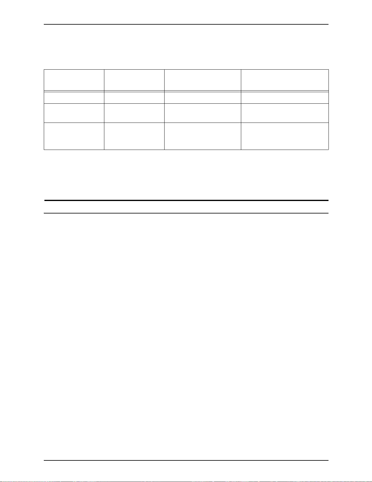
Table 1-1. Data stream resolution
Data stream Input resolution Print resolution:
DP155 and DP180
LCDS 300 by 300 dpi 600 x 2400 dpi 600 by 600 dpi
PostScript and PCL 300 by 300 dpi or
600 by 600 dpi
IPDS* 240 by 240 dpi* or
300 by 300 dpi or
600 by 600 dpi**
600 x 2400 dpi 600 by 600 dpi
600 x 2400 dpi 600 by 600 dpi
Print resolution:
DP100, DP115, and DP135
*Requires additional equipment to enable.
**600 by 600 dpi input resolution supported for full page IOCA
only
System components
The following figure shows the configurations supported for the
Xerox DocuPrint 100/115/135/155/180 EPS.
1-2 Installation Planning Guide
Page 21
Product overview
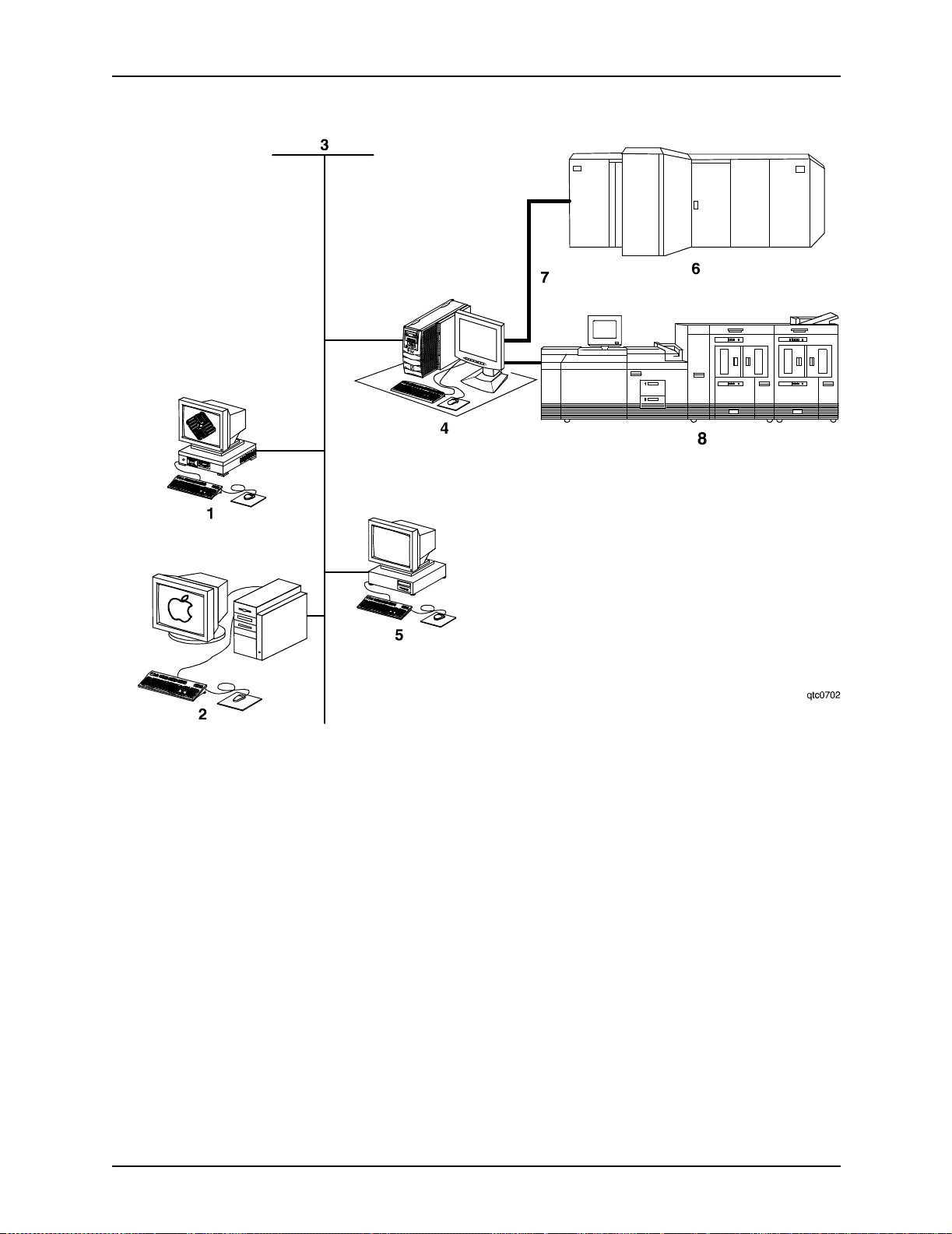
Figure 1-1. Configurations supported for the
Xerox DocuPrint 100/115/135/155/180 EPS
1. Sun UNIX client workstation
2. Apple Macintosh client workstation
3. Network connection
4. Controller
5. PC client workstation
6. Mainframe host computer
7. Bus and tag cables (channel connection)
8. Print engine
Installation Planning Guide 1-3
Page 22

Product overview
The following sections briefly describe the functionality of each
system component.
DocuPrint 100/
115/135/155/180
EPS
Customer-
supplied client
workstation
The DocuPrint 100/115/135/155/180 EPS includes the controller,
printer , printer in terf ac e, an d all appr opriate softw are . “Do cuPrint
printer” or “printer” refers to the base printer engine (IOT) only,
without the controller and interface.
A host mainframe computer or network-connected PC, Apple
Macintosh, or Sun UNIX client workstation submits print jobs to
the printing system. The print job may be in any of the following
data formats :
• PostScript levels 2 and 3
• HP PCL5c, PCL 5e , and P CL6: He wl ett-Packard Print Control
Language
• LCDS: Line Conditioned Data Stream
• IPDS: Intelligent Printer Data Stream
• ASCII: American Standard Code for Inf ormation I nte rch an ge
• PDF: Portable Document Format
• TIFF: Tagged Image File Format
• VIPP: Variable Data Intelligent PostScript Print Ware
Customer-
supplied network
and channel
connection
NOTE: Enablement of IPDS data format may require additional
equipment. Contact your local Xerox repre sentative for more
information.
The customer needs to supply one or more of the following
communication connections:
• Ethernet local area netwo rk (LAN) running TCP/IP, AppleTalk,
or Novell NetWare network protocol software.
• Online (channel -attached): Bus and t ag cables sup porting the
IBM 3211/4245 inter face.
• Token ring LAN running TCP/IP, Novell 3.x, or AppleTalk
network protocol software.
NOTE: Enablement of channel-attached and Token Ring
communication connection requires additional equipment.
Contact your local Xerox representative for more information.
1-4 Installation Planning Guide
Page 23
Product overview
Xerox-supplied
controller
Xerox-supplied
printer
The controller (monitor, processor, DVD drive, keyboard, mouse,
diskette drive, and cartri dge tape drive) accepts the print job
from the host mainframe computer or network-connected client
workstation, converts the files into page images, and sends the
page images to the print engine. External 9-track and 18/36track tape drive s can b e used for resource load ing an d f o r of fline
printing.
The printer (also known as the image output terminal [IOT] or
print engine) accepts page image data from the controller and
prints the document according to the print options specified by
the user. The printer also handles paper stacking, collating, and
optional finishing.
NOTE: It is the responsibility of the customer to supply, install,
and maintain hardware and software on any PC, Sun
workstation, or Macintosh workstation that is used to generate
documents for printing on the DocuPrint 100/115/135/155/180
EPS. You are also res ponsible for obtaining, installing, and
maintaining the required Ethernet local area network,
transceivers, bus and tag cables, and any other connecting
cables.
The Xerox DocuPrint 100/115/135/155/180 EPS prints LCDS
data from a mainfra me host compute r , emul ating an IBM 4245 or
3211 line printer. The printing system can receive data over a
channel through bus and tag cables and through the Socket
Gateway or lpr using TCP/IP protocol.
Table 1-2. Throughput speed
Maximum throughput
Maximum
Printing system
DP100 EPS 100 ppm 100 ppm
DP115 EPS 115 ppm 115 ppm
DP135 EPS 135 ppm 154 ppm
DP155 EPS 155 ppm 155 ppm
DP180 EPS 180 ppm 206 ppm
throughput speed
speed with 7 by 10 inch/
178 by 254 mm paper
NOTE: Maximum throughput speed with 7 by 10 inch / 178 by
254 mm paper requires the 7 by 10 inch enablement kit.
Installation Planning Guide 1-5
Page 24

Product overview
Xerox is responsible for the physical installation and service of
the printer and controller hardware and software components.
You have the general responsibility for the site of ensuring that
the correct personnel, supplies, and network hardware and
software are available. Refer to the “Preparing for installation”
chapter f or a de tailed d escription of the shared respons ibilitie s of
the customer and of Xerox.
Client workstations and system software
To submit print jobs to the printing system, the customer needs
to provide the proper client hardware as well as operating
system and network software.
Supported hardware and operating systems
The Xerox DocuPrint 100/115/135/155/180 EPS supports the
following types of networked client workstations and operating
systems:
• Sun Workstation running Sol aris 2.3 or higher
• PC running MS-DOS 5.0 or higher, using Ethernet with TCP/
IP or Novell NetWare 3.11 or higher, Windows 95/98,
Windows NT 4.0, Windows Millennium, Windows 2000, or
Windows XP
• PC running MS-DOS 5.0 or higher, with one or more of the
following TCP/IP packages:
– PC/TCP Network Software by FTP Software, Inc.
– Pathway Access by Wollongong G r oup, Inc.
– PC-NFS by Sun Select
• Apple Macintos h running 8. 6 thro ugh 9.x, or 10.1 or hig her in
Classic mode, using AppleTalk through Ethernet
• Any system that supports RFC-1179 lpr/lpd
The printing system software may be compatible with
workstation model s and softwar e versi ons other than those listed
above.
1-6 Installation Planning Guide
Page 25

Client networking software
Xerox client software, a third-party TCP/IP lpr networking
software, Novell, or Apple/Macintosh Printer Access Protocol
(PAP) networking software must be installed on your client
workstations or downloaded from the controller. This software
provides an interface with the controller, which allows you to
submit print jobs and check job status.
NOTE: The printing optio ns that are available to a client user
vary according to the networking software loaded on the client
workstation.
Additional information on submitting jobs from a clie nt
workstation is specified in other documents that are part of this
publication set.
MICR printing features
Product overview
The DocuPrint 100/115/135/155/180 MX systems produce a
Magnetic Ink Character Recognition (MICR) line on negotiable
and turnaround documents such as checks and bills. The MICR
printing system prints documents using magnetic ink and special
fonts to create machine readable information that allows for quick
document processing.
In general, MICR is used to print accounting and routing
information on blank checks and other negotiable documents.
The magnetic encoding capabilities can be used for any printed
output.
Installation Planning Guide 1-7
Page 26
Product overview
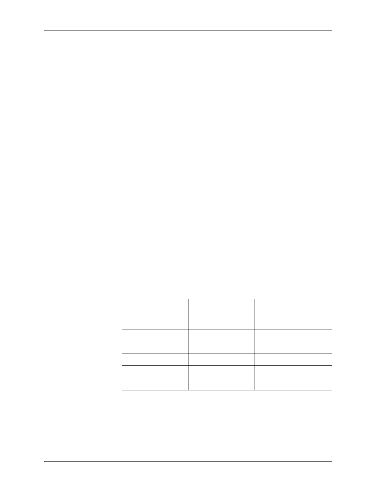
The following illustrates a check printed with a MICR line in U.S.
format. The entire MICR line, which consists of numbers and
characters (called symbols), is printed using magnetic ink.
ERA
PAY ROLL ACCOUNT
PAYTOTHE ORDER OF
ERA CORPORATION P.O.BOX 9968 KENAN,N.Y.146008
JEAN L.MAGNIN
484 NORTH PROSPECT
CARUBA BEACH, CA 80297
PAYABLE IF DESIRED AT SOUTHERN PACIFIC
NATIONALTRUST AND SAVINGS ASSOC.
OMAHA, NEBRASKA
SECURITYTRUST COMPANY OF KENEAN,N.Y.
Figure 1-2. Example of a check printed with MICR line (U. S.)
The DocuPrint 100/115/135/155/180 MX systems meet ABA
standards and ANSI and ISO specifications for automatic check
handling. They print the variable data and the MICR line at the
same time. This single-pass printing capability reduces
processing time and costs.
06-29-84
VO I D A F T E R 9 0 DAY S
NOT NEGOTIABLE
$* * * *980 28
12-35/9290
DOLLARS CENTS
MICR Line
1962721
$980.28
50-16
223
MICR fonts
Xerox provides a set of 300 and 600 dpi E13B and CMC7 MICR
fonts for use with your DocuPrint 100/115/135/155/180 MX
system. To receive the high print quality guaranteed by Xerox,
you must use these MICR fonts.
CMC7 fonts have been adopted in various countries outside of
the U.S., and are the official standard in France. Like the E13B
font, they are magnetically readable, but with a different
character design and recognition criteria. (Currently, CMC7 is
available only through Xerox Europe.)
1-8 Installation Planning Guide
Page 27

Product overview
IPS/NPS MICR
fonts
LCDS MICR fonts The MICR fonts that are used for printing an LCDS data stream
The MICR fonts for DocuPrint IPS and NPS include the following.
E13B fonts:
• E13B
• E13B Landscape
• E13B Test
• E13B Test Landscape.
CMC7 fonts:
•CMC7
• CMC7 Landscape
•CMC7 Test
• CMC7 Test Landscape
The “Test” fonts are non-readable MICR hollow bitmap (or
outline) fonts, provided for testing MICR ap plications a nd printing
non-negotiable documents.
include the following.
E13B4 fonts:
• E13B4 Portrait
• E13B4 Landscape
• E13B4 Inverse Portrait
• E13B4J
CMC7 fonts:
• CMC74 Portrait
• CMC74 Landscape
• CMC74 Inverse P ortrait
• CMC74J
Unsupported features
The DocuPrint 100/115/135/155/180 EPS does not support the
security and audit feature or bar code reading. In addition,
although the Line Thickening selection and the Virtual Printer
Imaging parameters are available when you use MICR, using
these features when printing MICR docu ments is not
recommended, as they corrupt the MI CR line.
Installation Planning Guide 1-9
Page 28

Product overview
In general, all print quality adjustments and enhancement
settings should be set at the nominal settings when printing
MICR output.
Host connectivity options
The Xerox DocuPrint 100/115/135/155/180 EPS can re ceive
data in the following ways:
• Over a channel through a bus and tag cable connection
• Through a network interface, using Novell, TCP/IP, or
AppleTalk protocols
Your system may have one or both of these configurations.
Remote diagnostics
Remote diagnostics is a unique suite of tools that allows Xerox
personnel to serve customers more effectively , and is intended to
automate and expedite the range of service-related support
functions.
The remote diagnostics capability is a no charge feature. To take
advantage of this feature, the customer needs to:
• Request remote diagnostic enablement through Xerox
Service
• Provide an analog phone line
• Provide a standard power outlet for a modem
For those customers unable to dedicate a phone line to the
modem, phone sharing devices are available for purchase.
Contact your local Xerox representative for more information.
1-10 Installation Planning Guide
Page 29

Controller overview
2. Controller components and options
This chapter describes the comp onents and options a v ail able f or
the Xerox DocuPrint 100/115/135/155/180 EPS controller.
The controller receives data from a mainframe host or a
workstation client, processes the data, and sends it to the printer.
The controller also provides the printer with print data and
commands, and receives status information from the printer.
The controller consists of a high performance Sun workstat ion
processor r unning Solaris software. Also resident on the
controller is the DocuSP software, which manages all printing,
diagnostic, and administrative functions on the printing system.
Accessing
DocuSP remotely
(Remote
Workflow)
The DocuSP software includes a full color graphical user
interface (GUI). Using the GUI, you set up and configure the
system, set up and implement system o ptions, a nd manage print
jobs.
Remote Workflow, a remote graphical user interface, is av ailable
for instal lation from a CD. The remote GUI allows y ou to ma nage
your DocuSP-based printers fr om a single PC or Sun
workstation. You may set your pr efere nces from the remote clie nt
to disable or enable some or all connections.
Remote Workflow allows you to configure the printers that you
want to manage, and provides real time status of the printers.
You may switch betw een the printers th at you are managing, but
you can display only one printer GUI at a time.
The Remote Workflow GUI looks and functions the same as the
local DocuSP GUI on the controller.
Installation Planning Guide 2-1
Page 30
Controller components and options
Controller components
The controller consi sts of a spec ially-c onfigured Sun w orkstation
and uses proprietary Xerox hardware, firmware, and software.
Your controller has one of two possible configurations, described
in the following sections.
NOTE: Controller hardware configurations are subject to
change, to keep up with technology advances.
Sun Blade workstat ion
The controller is base d on either the Su n Blade 1000/2 000 or the
Sun Blade 2500, workstations with high-performance
architecture for complex processing tasks.
Sun Blade 1000/
2000 configuration
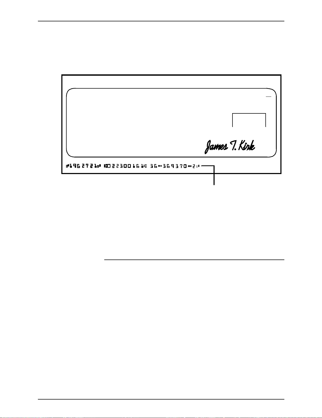
Figure 2-1. Sun Blade 1000/2000 controller
1. Controller stand
2. Mouse
3. 18/36-track cartridge tape drive (optional)
4. Processor
2-2 Installation Planning Guide
Page 31

Controller components and options
5. Diskette drive
6. DVD-ROM drive
7. Quarter-inch cartridge (QIC) tape drive
8. External fixed disk drive (optional)
9. Keyboard
10.Display monitor
The Sun Blade 1000/2000 contains the following hardware
components:
• Processor (system unit) containing the following:
– One or two UltraSPARC III high-speed central processing
unit (CPU) modules
• DP 100, 115, and 135: 1 CPU
• DP 155 and 180: 2 CPUs
NOTE: In XE, all printers use a dual CPU configuration.
– 1 or 2 GB of memory (one or two 1-GB Dual In-line
Memory Modules, or DIMMs)
• DP 100, 115, and 135: 1 GB
• DP 155 and 180: 1 or 2 GB
NOTE: In XE, all printers use a 2 GB memory
configuration.
– Hard disk drive
• Sun Blade 1000: 36 GB
• Sun Blade 2000: 73 GB
– High-density, read-only DV D-ROM drive
– Diskette drive: uses 3.5 inch, 1.44 MB, double-sided,
high-density diskettes
–Ethernet
– Two Printer Controller Interface (PCI) boards to interface
with the printer
– PGx64 video graphics board
• Universal Serial Bus (USB) keyboard and three-button
mouse
• 17-inch flat panel monitor
Installation Planning Guide 2-3
Page 32

Controller components and options
Sun Blade 2500
configuration
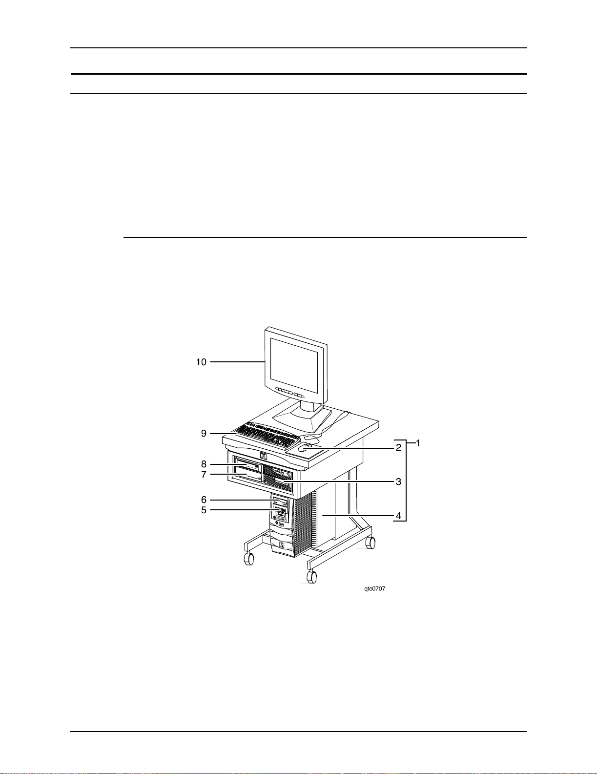
Figure 2-2. Sun Blade 2500 controller
1. Display monitor
2. External diskette drive
3. Keyboard
4. Mouse
5. External fixed disk drive (optional)
6. Quarter-inch cartridge (QIC) tape drive
7. Processor
8. DVD-ROM drive
9. 18/36-track cartridge tape drive (optional)
10.Controller stand
2-4 Installation Planning Guide
Page 33

Controller components and options
The Sun Blade 2500 contains the following hardware
components:
• Processor (system unit) containing the following:
– One UltraSPARC IIIi high-speed processing unit (CPU)
module
– 1 or 2 GB of memory (one or two 1-GB Dual In-line
Memory Modules, or DIMMs)
• DP 100, 115, and 135: 1GB
• DP 155 and 180: 2 GB
NOTE: In Xerox Europe, all printers use a 2 GB memory
configuration.
– 36 GB hard disk drive
– High-density, read-only DV D-ROM drive
– Ethernet
– One or two Printer Controller Interface (PCI) boards to
interface with the printer
• DP 100, 115, and 135: 1 board
• DP 155 and 180: 2 boards
– XVR-100 video graphics board
• Universal Serial Bus (USB) keyboard and three-button
mouse
• 17-inch flat panel monitor
• Diskette drive (external)
Processor The central processing unit contains the memory, internal disk
drive, a graphics board, a DVD-ROM drive, a diskette drive,
power receptacle and outlet, connectors and ports.
• Memory: Two 1 GB Dual In-line Memory Modules, or
DIMMs, are provided as a standard feature of the processor.
• Hard disk drive: A 36 or 73 GB primary disk drive is
provided as a standard feature of the processor. The
operating system, the NPS/IPS application, and any queued
print jobs are stored on the internal disk. This disk cannot be
used to store oth er app licati ons or d ata except as directe d b y
your service representative.
Installation Planning Guide 2-5
Page 34

Controller components and options
• DVD-ROM drive : The DVD-ROM drive is a high density,
read-only, optical laser storage device used for loading the
NPS/IPS operating system and other files. The CD-ROM
drive is located in the processor above the diskette drive.
Figure 2-3. Drive locations on the Sun Blade 1000/2000
processor
1. DVD-ROM drive
2. Diskette drive
2-6 Installation Planning Guide
Page 35

Controller components and options
Figure 2-4. DVD-ROM drive location on Sun Blade 2500
processor
• Back panel: The back panel of the processor has a power
receptacle an d outlet, connec tors, connector openings, and
ports. The following figure shows the back pan el of the
controller.
Installation Planning Guide 2-7
Page 36

Controller components and options
Figure 2-5. Back panel of the Sun Blade 1000/2000
controller
1. Access panel lock block
2. Serial connectors A and B, DB-25
3. Parallel connector
4. SCSI connector
5. Universal serial bus (USB) connectors (for keyboard and
for mouse)
6. Twisted-pair Ethernet (TPE) connector
7. IEEE 1394 connectors
8. Fibre Channel-Arbitrated Loop (FC-AL) connector
9. Audio module headphones, line-in, line-out, and
microphone connectors
2-8 Installation Planning Guide
Page 37

Controller components and options
10.Graphics card / video connector (frame buffer 0)
11.PCI card slot 4
12.Graphics card / video connector (frame buffer not used)
13.PCI card slots 3 and 2
14.Pow er connector
15.PCI card slot 1
Figure 2-6. Back panel of Sun Blade 2500
1. Parallel connector
2. Audio module headphones, line-in, line-out, and
microphone connectors
3. PCI card slots 4 and 5
4. Graphics accelerator
5. PCI card slots 0, 1, and 2
Installation Planning Guide 2-9
Page 38

Controller components and options
6. External UltraSCSI connector
7. Twisted-pair Ethernet
8. Serial connector
9. USB connectors (The diskette drive may be plugged into
any one of these.)
10.Pow er connector
Keyboard The keyboard consists of alphanumeric keys similar to a
typewriter, symbols and special character keys, an extended
character set, and function keys. The keyboard is one of your
main methods of communicating with the printer. You can use
the keyboard to make selections, and to enter commands that
control functions such as requesting sample prints, or shutting
down the system.
Mouse The mouse is another main method of communicat ing with the
printer.
Display monitor The 17-inch LCD monitor allows you to interact with the printer
and to monitor its interaction with the various components.
During a print job, printer error messages may display to notify
you of any unexpected conditions.
Diskette drive The external diskette drive plugs into the back panel of the
processor. Diskettes inser ted into a diskette drive are used to
install fonts and to load files to, and back up files from, the
internal disk drive. The diskette drive uses industry standard 3.5
inch, 1.44 MB, double-sided, high-density diskettes.
Optional
processor
components
The controller may be configured with any of the following
optional components:
• Connectivity board to enable Token Ring
• Channel interface board for channel connection to a host for
online LCDS printing
• One SCSI board to connect to an external tape drive
2-10 Installation Planning Guide
Page 39

• Graphics bo ard:
– PGx64 (Sun Blade 1000/2000)
– XVR-100 (Sun Blade 2500)
– Creator-3D series 3 graphics board
NOTE: The PGX64 graphics board is provided as a
standard feature of the processor. If more than one
connectivity option is installed, the PGx64 board is
replaced by the Creator3D graphics board.
Controller interface options
Your printing system may be configured for either the online
interface, the offline interface, or both.
Controller components and options
Online interface
The online (chann el-attached) interface receives input directly
from any en vironme nt that su pports the IBM 3211 and 4245 ho st
systems.
Tape drive option
The 36-track cartridge tape drive is an option. Your printing
system supports the following tape drives for offline printing and
importing and exporting of resources:
• 9-track open reel tapes
• 36-track cartridge tapes
Installation Planning Guide 2-11
Page 40

Controller components and options
Figure 2-7. Peripheral cabinet with tape drives
1. 9-track open reel tape drive
2. 18/36-track cartridge tape drive
If you have other Xerox printing systems, you may already have
a peripheral cabinet that houses a 9-track open reel and an 18/
36-track cartridge tape drive. The DocuPrint 100/115/135/155/
180 EPS supports existing peripheral cabinets, but the
peripheral cabinet option is not available with new systems.
The following 18-track tape drives are not supported:
• STK 4220 MOD 1 tape drive (3480)
• STK 4220 MOD 2 tape drive (3490)
2-12 Installation Planning Guide
Page 41

Printer components
3. Printer components and options
The printer processes the page images re cei ved from the
controller and produces the printed output. This chapter
describes the components and options available for the Xerox
DocuPrint 100/115/135/155/180 EPS printer.
The standard printer compone nts are the printer control console,
the sample tray, the purge tray, the two processor feeder trays,
and the feeder/stacker module or modules.
The base configur ation for the printer includes an inv erter fe eder /
stacker and one additional feeder/stacker module.
Figure 3-1. Printer base components
1. Printer control console
2. Sample tra y
3. Attention light
4. Purge tray
5. Feeder/stacker module
6. Inverter feeder/stacker module
7. Processor f ee der tr ays
Installation Planning Guide 3-1
Page 42

Printer components and options
The printer provid es control b uttons and displa ys f or ba sic printer
functions and status information. The printer control console
displays messages and graphics that assist you with jam
clearance and printer maintenance. Labels are located
throughout the printer to assist you with a variety of tasks such
as clearing a paper jam.
Refer to the Xerox DocuPrint 100/115/135/155/180 Ente rprise
Printing System Operator Guide for detailed description of the
features and operation of the printer components.
Printer control cons ole
The printer control console is the color monitor located on top of
the printer. It displays messages and graphics that alert you to
paper jams and other f ault an d status conditions (su ch as low dry
ink). It also contains buttons that allow you to control certain
functions of the printer (for example, continuing an interrupted
job) without returning to the controller.
The printer co ntrol console has the following features:
• Local controls and displays for jam clearance, loading
paper, unloading output, and diagnostics and service (used
by the service representative). Two types of messages are
displayed on the printer control console: fault messages,
which relate to printer malfunctions; and information
messages, which relate to printer conditions such as low dry
ink.
• Touch-sensitive areas that allow you to select options by
touching the console screen. A tone sounds when you touch
one of these areas.
• Attention alarm tone consisting of three beeps , repea ted for
ten seconds. The alarm sounds for any event that stops the
printer and requires operator attention. The alarm may be
disabled by the operator.
The tone stops after three cycles, or when the fault condition
is cleared or clearing has started (for example, doors or
covers specified in the clearance instructions are opened).
You can stop the tone by pressing one of the printer control
console buttons or by selecting a function through the touch
screen.
3-2 Installation Planning Guide
Page 43

Printer components and options
Figure 3-2. Printer control console
1. Language icon
2. Printer icon
3. Fault List icon
4. Tools icon
5. Guarded Tools icon
6. Clear button
7. Continue button
8. Stop button
9. Sample but ton
10.Brightness control thumbwheel
11.Icon area
12.Message area
Installation Planning Guide 3-3
Page 44

Printer components and options
Refer to th e customer document ation for a detailed description of
the features and operation of the printer control console
components.
Printer configurations
The Xerox DocuPrint 100/115/135/155/180 EPS is available in
sev eral di ffere nt configur ations, which allo w you to customiz e the
printing system for increased efficiency and for specialized
applications.
• Inverter feeder/stacker + 1 feeder/stacker
• Inverter feeder/stacker + 2 feeder/stackers
• Inverter feeder/stacker + 3 feeder/stackers
These configurations are illustrated below.
Figure 3-3. Printer with inverter feeder/stacker and
one feeder/stacker
Figure 3-4. Printer with inverter feeder/stacker and
two feeder/stackers
3-4 Installation Planning Guide
Page 45
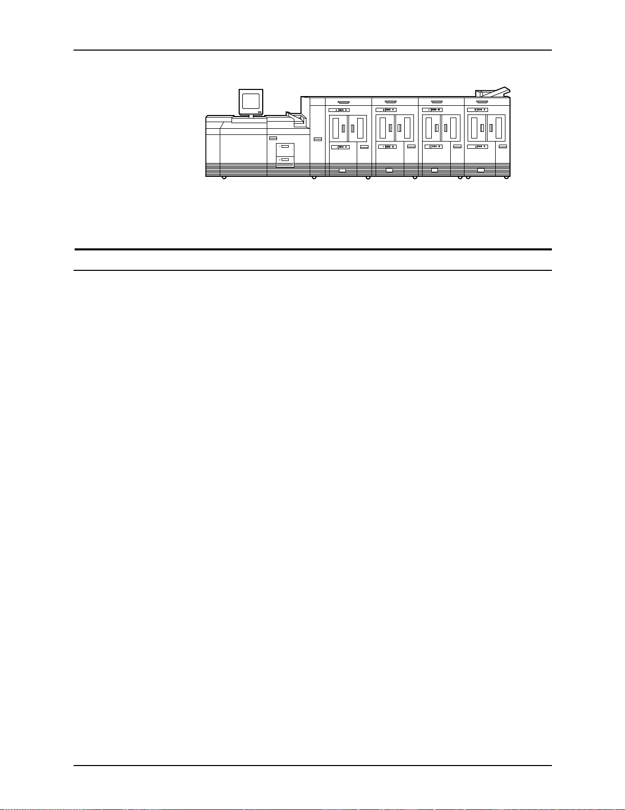
Figure 3-5. Printer with inverter feeder/stacker and
Bypass transport option
The bypass tran sport option provides an interf a c e bet w e en the
DocuPrint 100/115/135/155/180 EPS and your finishing
accessories. However, finishing devices require separate power
sources that are independent of the printing system.
Printer components and options
three feeder/stackers
Function of the
bypass transport
Paper stocks
supported on
bypass transport
The bypass tr ansport option enab le s third pa rty finishing de vices
to interface directly with the printing system. The bypass
transport allows you to customize your printer for increased
efficiency and specialized applications involving finishing.
NOTE: A bypass transport must be installed for the printing
system to support a third party finishing device.
Connected to the last feeder/stacker module, the bypass
transport moves paper from the stacker to a third party finisher
such as a stitcher, booklet maker, tape binder, and so on. By
making selections on the user interface windows, you can
program the printer to send output to th e bypa ss transport, which
directs the output to the finishing equipment.
The bypass transport accepts all paper stocks on which the
printer can print, and it accommodates simpl ex and duplex
printing.
Installation Planning Guide 3-5
Page 46

Printer components and options
Bypass transport
printer
configurations
The following printer configurations may have the bypass
transport, illustrated below:
• Printer with inverter feeder/stacker and 1 feeder/sta cker
• Printer with inverter feeder/stacker and 2 feeder/sta ckers
Figure 3-6. Printer with inverter feeder/st acker,
one feeder/stacker, and bypass transport
Figure 3-7. Printer with inverter feeder/st acker,
two feeder/stackers, and bypass transport
Roll feeder support (DP155 and DP180 EPS only)
The roll feeder option may be installed in the inverter feeder/
stacker module, replacing the feeder tray. This option does not
require DFA or input enablement software, or any additional
hardware.
The maximum number of feeder/stacker modules supported for
this configuration is four, including the inverter module with the
roll feeder. With the two processor feeder trays, this makes a
total of six input trays possible.
3-6 Installation Planning Guide
Page 47

4. Preparing for installat ion
This chapter assists you in preparing for the installation of your
Xerox DocuPrint 100/115/135/155/ 180 EPS. Use this chapter in
conjunction with the Getting Ready f o r Installation manual.
Preparing for installation is a respo nsibility shared by personnel
at your site and Xerox. Your Xerox representatives are available
to discuss installation issues and to assist you in completing the
site installation tasks.
Before installation, you must select and prepare an appropriate
location for the printing system and order supplies. This chapter
helps you accomplish these tasks by provid ing the following
information:
• A summary of your responsibilities and those of your Xerox
service representative
Responsibilities
• A checklist of installation planning activities.
For information on contro ller power and space requirements,
refer to the “Controller specific ations and requirements” chapter
of this guide. For facts about printer power and space
requirements, refer to the “ Printer specific ations and
requirements” chapter of this guide.
This section describes your site responsibilities and the
responsibilities of your service representatives. Some joint
responsibilities are included.
Installation Planning Guide 4-1
Page 48

Preparing for in stallation
Xerox responsibilities
This section lists the responsibilities of the service
representatives and systems analysts before, during, and after
installation:
• Site selection
– Assist in site selection
– Inspect and approve the site
• Installation
– Schedule the delivery of the hardware
– Monitor installation activities
– Assist you in ordering any supplies required
– Install the printing system
– Install LCDS system resource files, if applicable
• Training
– Provide initi a l operator training
– Provide information and assistance in registering for
Xerox Customer Educat ion classes or obtaining tutorials
• Service
– Review preventive maintenance schedules and service
call procedures
– Provide ongoing maintenance
– Assist in resolving hardware and software problems
– Obtain software licenses as appropriate
Customer responsibilities
Your responsibilities before, during, and after installation of the
DocuPrint printing system are to schedule and monitor your
installation activities. Refer to the installation planning checklist
in this chapter for a complete list of responsibilities.
Refer to t he “Xero x support services” appendix f or inf ormation on
services designed to support you before, during, and after your
installation.
4-2 Installation Planning Guide
Page 49

Preparing for installatio n
NOTE: Operating system software is not the same f or all printing
systems. Therefore, make sure that your system specialists are
familiar with the operating syste m software that is specific to your
DocuPrint system. If your system specialists are f amiliar with one
operating systems and you are converting to, or adding another,
they should be famil iar with the differences.
Site personnel Identify the person (or persons) at your site who will be the
primary interface with Xerox.
After the installation of the printing system, there are a few
ongoing tasks that must be performed. These tasks may include
all or some of the following:
• Meter reading and reporting
• Overseeing routine maintenance
• Placing service calls for hardware problems
• Ordering additional documentation, software, or fonts
• Arranging addi ti o na l ope rator training
• Maintaining an adequate inventory of consumable supplies.
It is your responsibility to designate a person (or persons) to
perform these tasks.
Operator and
systems training
Site preparation Select and prepare the site for system installation (including
Network
installation
Channel-attached
printing
Select personnel for operator and systems training and set up a
training schedule.
proper power, air conditioning, and work space). If connecting to
other equipment, obtain the necessary interfaces, cables,
transceivers, phone lines, and so forth.
Install the necessary network components required to connect
client workstations to the printing system. Refer to the Getting
Ready for Installation manual for details.
Obtain and install fully populated bus and tag cables required to
connect the host to the printing system. Refer to the Getting
Ready for Installation manual for details.
Client
workstations
Installation Planning Guide 4-3
Make sure all client workstations that will be submitting print jobs
have the proper hardware, operating system, and networking
software required by the printing system as client platforms.
Page 50

Preparing for in stallation
Applications Work with your Xerox systems analyst to determine
requirements for initial applications.
Installation planning checklist
To aid you in planning for printer installation, the following
checklist contains the tasks that you and your service
representative must complete before installation. (A copy of this
checklist also is provided in Getting Ready for Installati on.) If y ou
have questions about any of these activities, contact your sales
or service representative.
Use the time frames in this checklist as guidelines. It is best to
consult your suppliers to determine the required lead times.
Table 4-1. Installation planning checklist
Week Activity Responsibility
Date
completed
-4 • Select location for the printing system.
• Order additional sets of documentation, as
necessary.
• Register for Xerox Customer Education classes
and order tutorials, as necessary.
• Schedule printer delivery.
-3 • Schedule hardware delivery.
• Prepare site:
– Ensure proper electrical outlets are installed.
– Install network to system location, if
applicable.
– Install channel to system location, if
applicable. Cables must be fully populated.
– Ensure proper operating environment.
-2 • Inspect and approve site.
• Order consumable suppli es. Minimum suppl ie s
needed for installation:
– Paper (2 carton s)
– Developer (1 carton)
– Fuser agent (2 boxes)
– Dry ink (1 carton)
After installation, you will need to establish a
procedure for ordering supplies according to your
ongoing production requirements.
Customer
Customer
Customer and Xerox
Xerox
Customer and Xerox
Customer
Xerox
Customer and Xerox
_________
_________
_________
_________
_________
_________
_________
_________
_________
_________
_________
-1 • Schedule operator training. Customer and Xerox _________
4-4 Installation Planning Guide
Page 51

Preparing for installatio n
Table 4-1. Installation planning checklist (Continued)
Week Activity Responsibility
Date
completed
Install • Ensure supplies are available.
• Ensure system administrators are available
during software installation.
• Provide applicable completed worksheets from
the Getting Ready for Installation document.
If the NPS/IPS Extension option is being
installed, provide applicable information as
directed in the 96/4635/180 NPS/IPS Installation
Planning Guide.
• Install printing system hardware and software.
• Have operators available for training.
• Check documentation and software kits for
completeness.
• Have test jobs ready to run.
• Provide stocks needed for default input
configuration.
• Obtain and enable software license.
Postinstall
• Become familiar with support services available.
• Establish supplies maintenance procedure.
• Provide ongoing system maintenance.
• Adjust the printer alignment and magnification.
• Order additional documentation, as necessary.
Customer
Customer
Customer
Xerox
Customer
Customer
Customer
Customer
Customer
Customer
Customer
Customer and Xerox
Xerox
Customer
_________
_________
_________
_________
_________
_________
_________
_________
_________
_________
_________
_________
_________
_________
Connectivity requirements
An Ethernet local area network (LAN) running Transmission
Control Protocol/In ternet Protocol (TCP /IP), App leTalk, or Novell
NetWare soft w are is the n etwo rk communication syste m used to
transport documents from the client workstation to the printing
system.
Ethernet specifications
The Ethernet connection to the controller processor must be
compatible with the Institute of Electrical and Electronics
Engineers (IEEE) 802.3 standard.
The Ethernet interface on the controller process or is a 10 Mb/sec
twisted pair standa rd (10BaseT and 100BaseT). A ttachment Unit
Interface (AUI) Coax Ethernet is enabled with an adapter cable.
Installation Planning Guide 4-5
Page 52

Preparing for in stallation
Token Ring specifications
Channel-attached specifications
Work with your system administrator to assess what type of
network you ha ve and what modifica ti ons need to be ma de to
supply an Ethernet connector to the controller processor.
Users of network client workstations may send print jobs to the
printer usin g TCP/IP, Novell 3.x, or Appl e Talk network protocol.
The Token Ring connection to the controller processor must be
compatible with the Institute of Electrical and Electronics
Engineers (IEEE) 802.3 standard.
The controller processor has a 4 MB or 16 MB Token Ring Auto
interface (16 MB is preferred).
For an online configuration with an IBM host system, the
following cables must be available:
• Bus and tag cables (bus in, bus out, tag in, tag out)
• Terminators (as necessary, due to location on channel).
For your convenience, you may be able to order the bus and tag
cables through Xerox on a purchase-only basis. Contact your
Xerox sales representative for availability, current pricing, and
order information.
4-6 Installation Planning Guide
Page 53

Power requirements
5. Controller requirements and specifications
This chapter provides power and space requirements for the
controller. It also provides controller environmental
specifications.
For fa cts about printer power and space requirements, refer to
the “Printer specifications and requirements” chapter of this
guide.
Your controller has important power requirements that must be
accommodated. These requirements are summarized in the
table below.
For details on printer power requirements, refer to the “Printer
specifications and requirements” chapter of this guide.
Table 5-1. Controller electrical requirements
Sun Blade 1000
controller Voltage Amp service KVA rating NEMA
60 HZ 100 to 240 VAC 15 amp 0.4 KVA 5-15R
50 HZ 100 to 240 VAC 15 amp 0.4 KVA N/A
Agency certification: UL 1950, IEC 950, CSA 22.2 #950-1950,
FCC (Class A), and EN 550 22: 19 98 (C lass A) , and EN 6100 0-32: 1995 + A1-1998 + AZ 1998, EN6100-3-3: 1995 and EN
55024: 1998.
Installation Planning Guide 5-1
Page 54

Controller requirements and specifications
SA/C
y
Outlet configurations
This section discusses specifications for system outlets and the
required wall outlet configurations for the USA / Canada and
internationally.
NOTE: All power outlets must be dedicated to this equipment.
When determining the electrical connections f or printing system,
make sure that:
• Each power cord has a separate circuit.
• The print er power cord configurations ma tch your receptacle.
• Your electrical outlets are within the required specifications.
50 Hz systems: Ensure that power connections are per local
codes/regulations.
The following figure shows American, Canadian, and European
wall outlets in which to plug the controller.
NOTE: The optional 9 track and 18/36 track tape drives each
require an outlet identical to the o ne that is shown for the
controller.
U
AC Neutral
anada
AC Hot (ACH)
(ACN)
Earth Ground (GND)
United Kingdom
Europe
Earth
Earth
LiveNeutral
Suppl
Figure 5-1. Multinational wall outlet configurations
5-2 Installation Planning Guide
Page 55

Controller requirements and specifications
The required wall outlet voltages for USA / Canada, United
Kingdom, and the rest of Europe are as follows:
• USA / Canada: The voltage at the wall outlet is 100 to 120
VAC between AC hot and neutral, and between AC hot and
GND. The voltage is less than three VAC between GND and
neutral.
• United Kingdom: The voltage at the wall receptacle is 200 to
240 VAC between live and neutral, and between live and
earth. The voltage is less than three VAC between earth and
neutral.
• Europe: The voltage at the w all receptacl e is 20 0 to 240 VAC
between supply pins. The voltage between one supply pin
and earth is 200 to 240 VAC. The voltage between the other
supply pin and earth is less than 3 VAC.
Refer to the controller electrical requirements table earlier in this
chapter for a description of the power specifications for the
controller.
To reduce the risk of ele c trical shock, do not plug
components into any other type of power system. Contact
your facilities manager or a qualified electrician if you are
not sure what type of power is supplied to your work area.
Environmental specifications
The controller is a s turdy piece of eq uipment; however, like any
piece of electronic equipm e nt, it m ust be tr eat ed pr op erly. Avoid
extremes in temperature and other environmental hazards.
Place the controller in a relatively dust-free area that is wellventilated to avoid overheating.
In general, if your working environment is comfortable for you, it
is suitable for your controller. The following sections define the
acceptable environmental ranges for the two controller models
with which your system may be configured.
WARNING
Installation Planning Guide 5-3
Page 56

Controller requirements and specifications
Sun Blade 1000/2000 environmental require ments
• Temperature: 32 to 104 degrees F / 0 to 40 degrees C
• Humidity: 5 to 80% (relative non-condensing)
• Altitude: 0 to 10,000 feet (0 to 3,050 m) above sea level
• Heat dissipation: 1,100 BTU per hour (processor and
monitor)
For recommended environmental ranges for the printer work
area, refer to the “Printer specifications and requirements”
chapter of this guide.
Sun Blade 2500 environmental requirements
• Temperature:
– Without tape drive: 32 to 104 de gree s F/0 t o 40 de gree s C
Space requirements
– With tape drive: 41 to 95 degrees F/5 to 35 degrees C
• Humidity: 10 to 93% (relative non-condensing)
• Altitude: 0 to 9842.5 feet / 0 to 3,000 m above sea level
• Heat dissipation: 1,570 BTU per hour (processor and
monitor)
For recommended environmental ranges for the printer work
area, refer to the “Printer specifications and requirements”
chapter of this guide.
This section provides recommendations for placement of
controller hardware components.
For printer component space requirements, refer to the “Printer
specifications and requirements” chapter of this guide. Contact
your service represent ative if you ha ve questions not specifica lly
addressed in this guide.
5-4 Installation Planning Guide
Page 57

Controller placement
The controller must be positioned within the line-of-sight of
the printer for safety purposes while servicing the
equipment.
The controller components are placed in the accompanying
controller stand. You should consider the following factors when
deciding where to place the controller and stand:
• There should be at least 36 inches / 15.2 cm of clearance on
all sides of the controller stand.
• Adequate work space and service clearance around the
equipment
• Proximity to electrical and network connectors
• Security of the work area. You may need to place the system
in an area where you can restrict access to it.
Controller requirements and specifications
WARNING
Guidelines for controller placement
To ensure consistent performance and avoid any damage to
equipment, follow these rules for placing the components of the
controller.
Do:
• Use the controller stand that comes with y our printing system
equipment.
• Allow at le ast 6 inches / 152 mm of unob structed space at th e
front and rear of the processor, so the fan and vents are not
blocked.
The following illustration shows fan and vent locations on the
front and back of t he processor.
Installation Planning Guide 5-5
Page 58

Controller requirements and specifications
Figure 5-2. Sun Blade 1000 /2000 fan and vent locations to
keep clear
1. Vents in front of processor
2. Vents in back of processor
5-6 Installation Planning Guide
Page 59

Controller requirements and specifications
Figure 5-3. Sun Blade 2500 fan and vent locations to keep
clear
1. Vents in front of processor
2. Vents in back of processor
Do not:
• Place the monitor and processor on a desk or table top.
• Do not place the monitor on top of the processor.
• Do not allow an y piece of equip ment to b low w arm air into the
air intake vents of the processor.
• Do not place the processor on its side, or in any other
position but the upright, vertical position achieved by using
the controller stand.
• Do not place the processor or monitor on top of the printer.
Installation Planning Guide 5-7
Page 60

Controller requirements and specifications
Controller hardware specifications and requirements summary
The following tables summarize the specifications and electrical
requirements of your controller hardware components.
For a summary of printer hardware specifications and
requirements, refer to the “ Printer specific ations and
requirements” chapter of this guide. Contact your local Xerox
representative if you have questions not specifically addressed
in this guide.
Table 5-2. Sun Blade 1000/2000 specifications
Dimensions (depth,
Device
Stand d=35.5 in / 90.2 cm
Processor d=25 in / 63.5 cm
Monitor d=10 in / 25.4 cm
width, height) Weight
w=30 in / 76.2 cm
h=38.25 in / 97.2 cm
NOTE: Add 3 in /
7.62 cm to stand’s
depth with channel
interface board and
channel cable
connector box.
w=10 in / 25.4 cm
h=17.75 in / 45.1 cm
w=17.5 in / 44.5 cm
h=18.5 in / 47 cm
195 lbs /
88.6 kg
70 lbs /
31.8 kg
18 lbs /
8.2 kg
Heat
dissipation Power requirements Cable lengths
--- --- ---
1,100 BTU
per hour
408 BTU
per hour
60 Hz:
100 to 240 VAC,
15 amp, 0.4 KVA,
5-15 NEMA
50 Hz:
100 to 240 VAC,
15 amp, 0.4 KVA
100-120 ~ VAC,
1 phase, 50-60 Hz,
3.0 amp, 0.4 KVA
200-240 ~ VAC,
1 phase, 50-60 Hz,
2.0 amp, 0.4 KVA
Power: 8 ft. /
2.4 m
Interface to
printer:
20 ft. / 6.1 m
usable length
Video cable to
processor:
46 in / 1.17 m
Quarter-inch
cartridge
tape drive
18/36 track
cartridge
tape drive
(optional)
W=7.5 in / 19 cm
H=2.7 in / 7 cm
D=13 in / 33 cm
W= 8.54 in / 21.7 cm
H= 5.39 in / 13.7 cm
D= 21.9 in / 55.6 cm
8.4 lbs /
3.8 kg
31 lbs /
13.4 kg
--- 100-240 VAC,
47-63 Hz,
max. 850 ma - 1.45
amp
--- 88-264 VAC,
48-62 Hz,
max. 35 amp
SCSI cable to
processor or
additional SCSI
device:
2.62 ft / 0.8 m
SCSI cable to
processor or
additional SCSI
device:
16.4 ft / 5 m,
32.8 ft / 10 m, and
65.6 ft / 20 m
5-8 Installation Planning Guide
Page 61

Controller requirements and specifications
Table 5-2. Sun Blade 1000/2000 specifications (Continued)
Dimensions (depth,
Device
External hard
disk drive
Keyboard d=7.5 in / 19.1 cm
Mouse d=3 in / 8 cm
Peripheral
cabinet
(existing
systems only;
not an opti o n
on new
systems)
width, height) Weight
W=7.5 in / 19 cm
H=2.7 in / 7 cm
D=13 in / 33 cm
w=20 in / 50.8 cm
w=4 in / 10 cm
h=2 in / 5 cm
--- --- --- 108/240 VAC
8.4 lbs /
3.8 kg
2 lbs /
1 kg
0.3 lbs /
0.14 kg
Heat
dissipation Power requirements Cable lengths
--- 100-240 VAC,
47-63 Hz,
max. 850 ma - 1.45
amp
--- --- 72 in / 1.8 m
--- --- 25 in / 63 cm
(1-phase), or
208/220 VAC
(line 1 to line 2)
15 amp
SCSI cable to
processor or
additional SCSI
device:
28 in / 71 cm
---
Installation Planning Guide 5-9
Page 62

Controller requirements and specifications
Table 5-3. Sun Blade 2500 specifications
Dimensions (depth,
Device
Stand d=35.5 in / 90.2 cm
Processor d=19.3 in / 49 cm
Monitor d=10 in / 25.4 cm
width, height) Weight
w=30 in / 76.2 cm
h=38.25 in / 97.2 cm
NOTE: Add 3 in /
7.62 cm to stand’s
depth with channel
interface board and
channel cable
connector box.
w=8.3 in / 21 cm
h=19 in / 48.3 cm
w=17.5 in / 44.5 cm
h=18.5 in / 47 cm
195 lbs /
88.6 kg
49.6 lbs /
22.5 kg
18 lbs /
8.2 kg
Heat
dissipation Power requirements Cable lengths
--- --- ---
1,570 BTU
per hour
408 BTU
per hour
60 Hz:
100 to 240 VAC,
15 amp, 0.4 KVA,
5-15 NEMA
50 Hz:
100 to 240 VAC,
15 amp, 0.4 KVA
100-120 ~ VAC,
1 phase, 50-60 Hz,
3.0 amp, 0.4 KVA
200-240 ~ VAC,
1 phase, 50-60 Hz,
2.0 amp, 0.4 KVA
Power: 8 ft. /
2.4 m
Interface to
printer: 20 ft. /
6.1 m usable
length
Video cable to
processor:
70 in / 1.8 m
Quarter-inch
cartridge
tape drive
18/36 track
cartridge
tape drive
(optional)
External hard
disk drive
W=7.5 in / 19 cm
H=2.7 in / 7 cm
D=13 in / 33 cm
W= 8.54 in / 21.7 cm
H= 5.39 in / 13.7 cm
D= 21.9 in / 55.6 cm
W=7.5 in / 19 cm
H=2.7 in / 7 cm
D=13 in / 33 cm
8.4 lbs /
3.8 kg
31 lbs /
13.4 kg
8.4 lbs /
3.8 kg
--- 100-240 VAC,
47-63 Hz,
max. 850 ma - 1.45
amp
--- 88-264 VAC,
48-62 Hz,
max. 35 amp
--- 100-240 VAC,
47-63 Hz,
max. 850 ma - 1.45
amp
SCSI cable to
processor or
additional SCSI
device:
2.62 ft / 0.8 m
SCSI cable to
processor or
additional SCSI
device:
16.4 ft / 5 m,
32.8 ft / 10 m, and
65.6 ft / 20 m
SCSI cable to
processor or
additional SCSI
device:
28 in / 71 cm
5-10 Installation Planning Guide
Page 63

Controller requirements and specifications
Table 5-3. Sun Blade 2500 specifications (Continued)
Dimensions (depth,
Device
External
diskette drive
Keyboard d=7 in / 17.8 cm
Mouse d=3 in / 8 cm
Peripheral
cabinet
(existing
systems only;
not an opti o n
on new
systems)
width, height) Weight
w=408 in. / 10.4 cm
h=.93 in. / 2.4 cm
d=5.93 in. / 15.1 cm
w=20 in / 50.8 cm
w=4 in / 10 cm
h=2 in / 5 cm
--- --- --- 108/240 VAC
.68 lbs /
.31 kg
2 lbs /
1 kg
0.3 lbs /
0.14 kg
Heat
dissipation Power requirements Cable lengths
--- --- USB cable to
processor:
11.8 in / 30 cm
Additional
extension cable
provided:
6 ft / 1.5 m
--- --- 89 in / 2.26 m
--- --- 25 in / 63 cm
--(1-phase), or
208/220 VAC
(line 1 to line 2)
15 amp
Installation Planning Guide 5-11
Page 64

Controller requirements and specifications
5-12 Installation Planning Guide
Page 65

Power requirements
6. Printer requirements and specifications
This chapter provides power and space requirements for the
DocuPrint 100/115/135/155/180 EPS printer. It also provides
printer environ m en tal specif ic at io ns.
For information about controller power and space requirements,
refer to the “Controller specific ations and requirements” chapter
of this guide.
Your printer has important power requirements t hat must be
accommodated. These requirements are summarized in the
table below.
For further details on power requirements, refer to the voltage
charts and wiring diagrams that follow.
For details on controller power r equirements, refer to the
“Controller specifications and r eq uirements” chapter of this
guide.
Table 6-1. Printer el ectrical requirements
Component Voltage Amp. service
Printer 60 Hz
(U.S. and
Canada)
Printer 50 Hz WYE (Star)
120/240 VAC or 120/208
VAC (Cord 1)
120/240 VAC or 120/208
VAC (Cord 2 for DP 155
and DP180 only)
380, 400, 415 VAC
(3 phase, 5 wire)
50 amp (Cord 1)
30 amp (Cord 2
for DP 155 and
DP180 only)
30 amp Consult local
Agency certification: UL 478 and 1950, IEC 950, CE Mark,
CSA 22.2 #220-1986, FCC (Class A), and VDE 0871 (Class A).
KVA rating
(operating mode)
Operating: 7.3
+ .75 per middle
module stacker
service
representative
Additional
Requirements
14-50R (Cord 1)
14-30R (Cord 2
for DP 155 and
DP180 only)
Installation Planning Guide 6-1
Page 66

Printer requirements and specifications
Outlet configurations
This section discusses specifications for printer outlets and the
required wall outlet configurations for the USA / Canada and
internationally.
NOTE: All power outlets must be dedicated to this equipment.
When determining the electrical connections for your printer,
make sure that:
• Each power cord has a separate circuit
• The print er power cord configurations ma tch your receptacle
• Your electrical outlets are within the required specifications
50 Hz systems: Ensure that power connections are per local
codes/regulations.
60 Hz printer outlet voltages
The following table shows the voltages for the outlets on your
printer. All power outlets must have a dedicated circuit for each
system equipment piece. Make sure each power cord has a
separate circuit.
Table 6-2. Printer (60 Hz) voltage requirements at power
outlet
Service outlet
configuration
4 Wire Line 1 to neutral 120 V RMS 107-127 V RMS
4 Wire Line 2 to neutral 120 V RMS 107-127 V RMS
4 Wire Neutral to
4 Wire Line 1 to line 2 208 V RMS 182-220 V RMS
4 Wire Line 1 to line 2 240 V RMS 210-254 V RMS
Measurement
of wiring Nominal Range
00-10 V RMS
ground
6-2 Installation Planning Guide
Page 67

Printer requirements and specifications
Printer power
outlet and cord
voltage
configurations–
60 Hz
The follo wing figu res sho ws the 60 Hz po wer out let configur ation
for 50 amp NEMA 14-50R and 30 amp NEMA 14-30R. Voltage
to ground is shown for troubleshooting purposes.
NEMA
14-50R
Figure 6-1. 60 Hz power configuration–50 amp
NEMA
14-30R
Figure 6-2. 60 Hz power configuration–30 amp
50 Hz printer outlet voltages
All power outlets must have a dedicated circuit for each system
equipment piece. Make sure each power cord has a separate
circuit.
NOTE: Consult with your service representative to ensure that
the installation conforms to your local electrical requirements.
Installation Planning Guide 6-3
Page 68

Printer requirements and specifications
WYE (or Star)
configurations–
50 Hz
For the 50 Hz WYE configuration, measure the WYE or Star
connection voltages at the power source.
Table 6-3. Printer (50 Hz) WYE (Star) 415 voltage
Service outlet
configuration
5 Wire 415 V Line 1 to line 2 415 V RMS 374-457 V RMS
5 Wire 415 V Line 2 to line 3 415 V RMS 374-457 V RMS
5 Wire 415 V Line 1 to Line 3 415 V RMS 374-457 V RMS
5 Wire 415 V Line 1 to neutral 240 V RMS 216-264 V RMS
5 Wire 415 V Line 2 to neutral 240 V RMS 216-264 V RMS
5 Wire 415 V Line 3 to neutral 240 V RMS 216-264 V RMS
Measurement
of wiring Nominal Range
The following lists the 50 Hz WYE/Star printer outlet information
for 380 and 400 volts.
Table 6-4. Printer (50 Hz) WYE (Star) 380 and 400 voltage
Printer power
outlet/cord voltage
configurations–50
Hz
Service outlet
configuration
5 Wire 380 V Line 1 to line 2 380 V RMS 342-419 V RMS
5 Wire 380 V Line 2 to line 3 380 V RMS 342-419 V RMS
5 Wire 380 V Line 1 to Line 3 380 V RMS 342-419 V RMS
5 Wire 380 V Line 1 to neutral 220 V RMS 198-242 V RMS
5 Wire 380 V Line 2 to neutral 220 V RMS 198-242 V RMS
5 Wire 380 V Line 3 to neutral 220 V RMS 198-242 V RMS
5 Wire 400 V Line 1 to line 2 400 V RMS 358-438 V RMS
5 Wire 400 V Line 2 to line 3 400 V RMS 358-438 V RMS
5 Wire 400 V Line 1 to Line 3 400 V RMS 358-438 V RMS
5 Wire 400 V Line 1 to neutral 230 V RMS 207-253 V RMS
5 Wire 400 V Line 2 to neutral 230 V RMS 207-253 V RMS
5 Wire 400 V Line 3 to neutral 230 V RMS 207-253 V RMS
Measurement
of wiring Nominal Range
For 50 Hz systems outlet/po wer cord configura tions, consult y our
local service representative to determine the type of plug and
receptacle to us e.
6-4 Installation Planning Guide
Page 69

Environmental specifications
When you select a location for your printer, avoid environments
with extreme variations in temperature and other hazards, such
as excessive dust or humidity. Recommended environmental
ranges for the work area are as follows:
Table 6-5. Printer environmental specifications
Condition Range
Printer requirements and specifications
Operating
temperature
Humidity Recommended:
Altitude: Normal:
Heat dissipation:
DP 155 and 180
(2-stacker
system)
DP 100, 115,
and 135
(2-stacker
system)
Audible noise Operating:
Recommended:
Minimum:
Maximum:
Minimum:
Maximum:
Maximum:
Operating:
Standby:
Energy Saver:
Operating:
Standby:
Energy Saver:
Continuous:
Impulse:
68° F to 76° F / 20° C to 24° C
50° F / 10° C
85° F / 29° C
45% ±10%
30%
65%
Up to 6,000 feet / 1,830 m
above sea level
9,000 feet / 2,743 m above
sea level
32,770 BTU/hour
4,454 BTU/hour
2,700 BTU/hour
28,140 BTU/hour
4,454 BTU/hour
2,700 BTU/hour
82 dB(A)
82 dB(A)
Standby:
Continuous:
Impulse:
52 dB(A)
N/A
Installation Planning Guide 6-5
Page 70

Printer requirements and specifications
Space requirements
You should consider the foll owing f actors wh en deciding whe re to
place the printer hardware components:
• Adequate work space and service clearance around the
equipment
• Proximity to electrical and network connectors
• Security of the work area. You may need to place the system
in an area where you can restrict access to it. This may be
important if your personnel need to print confidential
documents or if you are concerned with unauthorized usage.
Dimensions and weight s of the printer components are listed in
this section, along with diagrams, to help you visualize the sizes
and total space requir e me nts.
NOTE: There must be a 78 inch / 198 cm vertical clearance
throughout the entire area. In addition, your printer must be
installed in a fixed location with a minimum clearance space of
36 inches / 91.4 cm around all sides of each piece of equipment
for access by service personnel. In addition, there must be 50
inches / 126.9 cm clearance space in front of the printer.
For information on clearance space and other space planning
considerations, r efer to the “Space planning guidelines” section
of this chapt er. Contact your s ervice representative if you have
questions not specifically addressed in this guide.
Printer configurations available
The following configurations are available for the printer:
• Printer + inverter feeder/stacker + 1 feeder/stacker
• Printer + inverter feeder/stacker + 2 feeder/stackers
• Printer + inverter feeder/stacker + 3 feeder/stackers.
Measurements and a top-view diagram for each of t hese
configurations is provided on the following pages.
6-6 Installation Planning Guide
Page 71

Printer configuration diagrams
The following diagrams show space requirements for three
printer configurations.
Printer requirements and specifications
Printer with
inverter feeder/
stacker and
one feeder/stacker
The dimensions o f the printer wi th the inverter feeder/sta cker
and feede r/ stacker are as follows:
• Width: 151.25 inches / 384.2 cm
• Depth: 38.8 inches / 98.6 cm
• Height: 59.6 inches / 151.3 cm
• Weight: 2,5 88 po und s / 1174.9 kg
• Total space requirement: 223.25 by 114 inches / 567 by
290.3 cm
Figure 6-3. Printer with inverter feeder/stacker and
one feeder/stacker (top view)
1. Printer
2. Back of printer area
3. Inverter feeder/stacker
4. Feeder/stacker
5. Front of printer area
Installation Planning Guide 6-7
Page 72

Printer requirements and specifications
Printer with
inverter feeder/
stacker and
two feeder/
stackers
The dimensions of the printer w ith the inverter feeder/stacker,
and two feeder/stackers are as follows:
• Width: 183.50 inches / 466.1 cm
• Depth: 38.8 inches / 98.6 cm
• Height: 59.6 inches / 151.3 cm
• Weight: 3,1 09 po und s / 1,411.9 kg
• Total space requirement: 114 by 256.50 inches / 290.3 by
648.9 cm
Figure 6-4. Printer with inverter feeder/st acker and
two feeder/stackers (top view)
1. Printer
2. Back of printer area
3. Inverter feeder/stacker
4. Feeder/stacker
5. Feeder/stacker
6. Front of printer area
6-8 Installation Planning Guide
Page 73
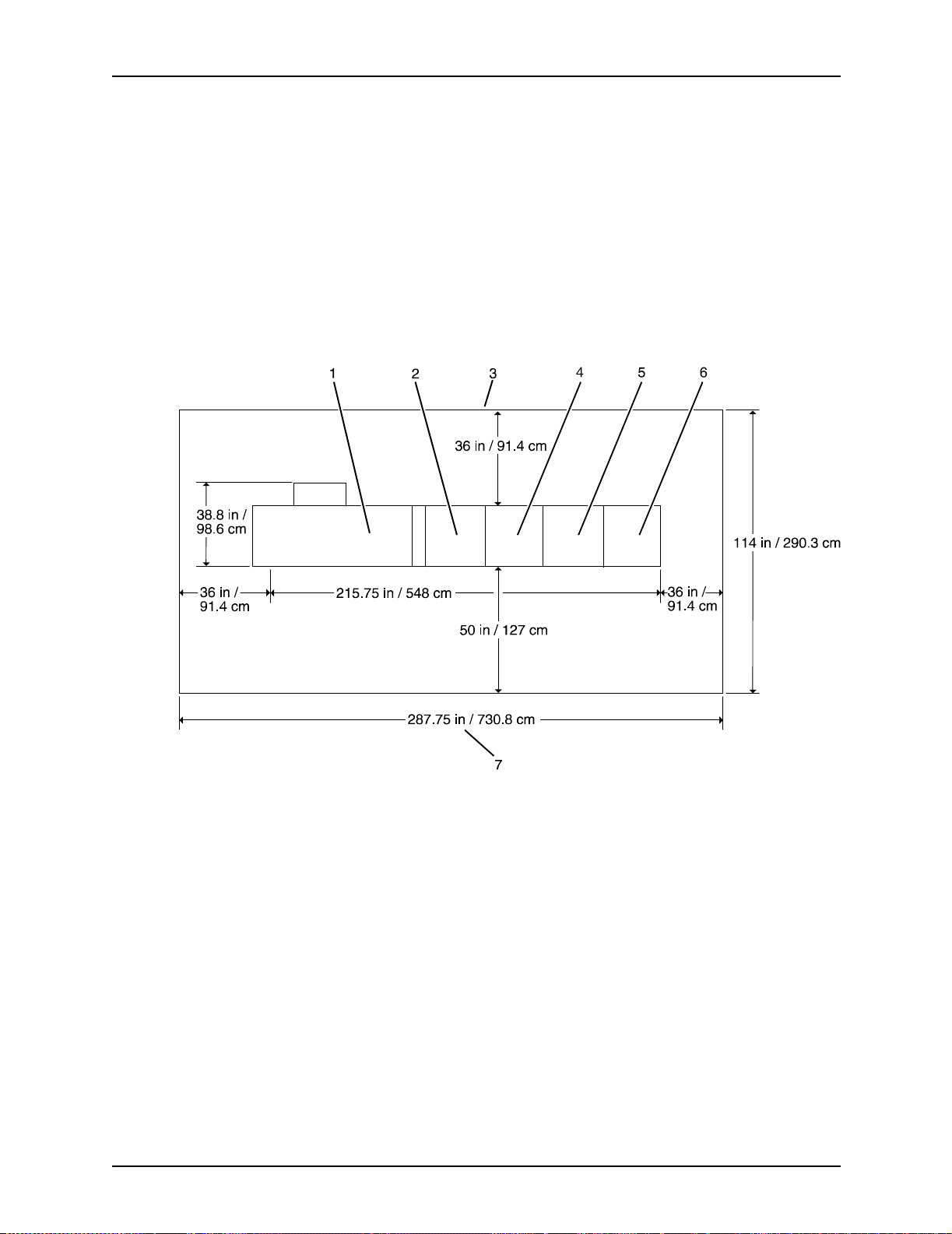
Printer requirements and specifications
Printer with
inverter feeder/
stacker and
three feeder/
stackers
The dimensions o f the printer wi th the inverter feeder/sta cker
and three feeder/stackers are as follows:
• Width: 215.75 inches / 548 cm
• Depth: 38.8 inches / 98.6 cm
• Height: 59.6 inches / 151.3 cm
• Weight: 3,630 pounds / 1,648.9 kg
• Total space requirement: 114 by 287.75 inches / 290.3 by
730.8 mm
Figure 6-5. Printer with inverter feeder/stacker and
three feeder/stackers (top view)
1. Back of printer area
2. Printer
3. Inverter feeder/stacker
4. Feeder/stacker
5. Feeder/stacker
6. Feeder/stacker
7. Front of printer area
Installation Planning Guide 6-9
Page 74

Printer requirements and specifications
Bypass transport specifications
The bypass transport option enables you to add a third-party
finishing device . The b ypass tra nsport is installed by y our service
representative and remains permanently in place. You should
not attempt to remove or reinstall it. The following is
supported by the bypass transport:
• Paper size and weight: You can use all of the paper sizes
and weights supported by the printer in the bypass transport.
• Sheet exit orientation: 1 to N (the same order in which
sheets are fed from the printer), delivered face down.
• Maximum throughput speed: The bypass transport for the
printer supports throughput speeds of up to 180 ppm (pages
per minute). This rate is based on stocks up to 9 by 14.33 /
229 by 364 mm in length.
• Sheet exit height: 34 inches / 86 cm above the floor.
Bypass transport dimensions
The following pages contain diagrams showing dimensions,
service access, and the paper path for the bypass transport.
Dimensions The following figure shows the dimensions of the bypass
transport in millimete rs and inches from the right end view.
6-10 Installation Planning Guide
Page 75

Printer requirements and specifications
Figure 6-6. Bypass transport dimensions
Installation Planning Guide 6-11
Page 76

Printer requirements and specifications
Service access The following figure provides space planning information and
service access requirements for the bypass transport.
Figure 6-7. Bypass transport space planning diagram (top
view)
1. Recommended third-party feeder hardware attaches at rear
of printer
2. Expected third-party input paper feed path
3. Neutral area, to remain unoccupied
4. Shaded areas at rear and right side of the bypass transport
require third-party input/output devices to be undockable
from the feeder/stacker or the bypass transport
5. Register edge of the output sheet
6. Third-party hardware must not extend more than 1 inch /
25 mm beyond bypass transport front cover line for correct
front door access
6-12 Installation Planning Guide
Page 77

Printer requirements and specifications
7. Bypass transport / input enablement jam clearance space is
required
Bypass transport
paper path
The following figure shows the paper path through the bypass
transport from a front view.
Figure 6-8. Bypass transport paper path
Installation Planning Guide 6-13
Page 78

Printer requirements and specifications
Configuration diagrams with bypass transport
The following diagrams show the dimensions and space
requirements of the printer with a bypass transport. These
diagrams re prese nt to p views of the compo nents , su rro unded b y
the minimum access space requirements on all sides.
Figure 6-9. Printer—inverter feeder/stacker and
one feeder/stacker with bypass transport
1. Printer
2. Inverter feeder/stacker
3. Back of printer area
4. Feeder/stacker
5. Bypass transport
6. Front of printer area
6-14 Installation Planning Guide
Page 79

Printer requirements and specifications
Figure 6-10. Printer—inverter feeder/stacker and
1. Printer
2. Inverter feeder/stacker
3. Back of printer area
4. Feeder/stacker
5. Feeder/stacker
6. Bypass transport
7. Front of printer area
Space planning guidelines
When determining your space requirements and planni ng for
shared space between your printers, it is important to consider
all of the components you plan to install.
To ensure all of the space requirements are met, it is important
to work with your Xerox representative.
two feeder/stackers with bypass transport
Installation Planning Guide 6-15
Page 80

Printer requirements and specifications
Before installation, you must consider the following:
• Clearance space re quirements wh ere yo u intend t o install the
printer
• Recommended cable lengths and locations (refer to the
“System connections” chapter of this guide for more
information)
• Delivery access requirements
• Floor leveling
Clearance space requirements
The printer must be installed in a fixed location that provides the
following clearance space:
• 36 inches / 91.4 cm on all sides of each component
• 78 inches / 198 cm of v ertical cleara nce throug hout t he entire
area
• 24 inches / 61 cm of exclusive operator area in front of each
component
NOTE: There must be a total of 50 inches / 126.9 cm of
clearance space in front of the printer.
Shared space between components
It is best to provide the full amount of clearance space around
the hardware components. Your environment may require you to
use shared space between components such as between the
printer and the controller or between the printer and another
Xerox printing system. You can share the 36-inch / 91.4 cm
clearance space around each component, as long as you follow
these rules:
• Space may be shared only with other Xerox equipmen t.
• Components may share the 36-inch / 91.4 cm general
service clearance areas, but they may not share the 24-inch /
61 cm operator area in front of each component.
• There must be 78 inches / 198 cm of vertical clearance
throughout the entire area.
6-16 Installation Planning Guide
Page 81

Printer requirements and specifications
NOTE: Finishers that are attached to your bypass tran sport may
occupy sha red space w ith Xerox equipment. Howe ve r, they must
be removable to allow servicing of the printer feeders and
stackers. Consult with your Xerox representative to ensure all
the requirements are met.
Shared space configuration diagrams
The following figures illustrate three possible configurations of
shared space.
Back-to-back
shared space
The figure below illustrates the two printers placed in a back-toback position. This allows the printers to share the entire 36
inches /
91.4 cm of general service space.
Figure 6-11. Back-to-back shared service area space
1. Operator area
2. Printer
Installation Planning Guide 6-17
Page 82

Printer requirements and specifications
Face-to-face
shared space
The following figure shows the two printers facing each other.
The printers share 26 inches / 30.5 cm of the general service
space, but not the exclusive operator area in front of each
printer. There f or e , the p rinters shou ld be sep arat ed b y 24 inch es
/ 61 cm, plus 24 inches / 61 cm, plus 26 inches / 30.5 cm. This
allows for the entire operator space for each printer, plus the
shared general service area of
26 inches / 30.5 cm.
Figure 6-12. Face-to-face shared service area space
1. Operator area
2. Printer
6-18 Installation Planning Guide
Page 83
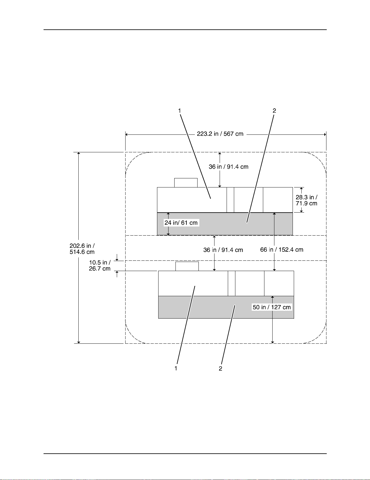
Printer requirements and specifications
Face-to-back
shared space
The following figure shows the two printers arranged with one
facing the back of the other. Between them is 60 inches / 152.4
cm of space. This allows for 24 inches / 61 cm of operator space
in front of the printer facing toward the other, plus 36 inches /
91.4 cm of service space behind the printe r f acing aw a y from the
other.
Figure 6-13. Face-to-back shared space
1. Operator area
2. Printer
Installation Planning Guide 6-19
Page 84

Printer requirements and specifications
Floor leveling
For proper operation, the printer must be perfectly level. On
floors less than two degrees out of level, installation personnel
use a leveling kit to level the machine.
NOTE: The printer will not function properly on floors more than
two degrees out of level.
If the floor is more than two degrees out of leve l, find another
location for the printer.
For your reference, two degrees represents a height discrepancy
of approximately 3.8 inches / 9.6 cm measured at the casters
with the printer tilting fr om left to right, or approximately 0.7
inches / 1.8 cm with the printer tilting from back to front.
If you move the printer after its initial installati on, it is your
responsibility to make sure that the printer can be leveled
properly . If y ou do not ha v e the le veling kit (the printer in its initial
location did not require it), and you need one to level the printer
in a new location, contact your Xerox site representative to
obtain one.
Delivery access requirements
It is easy to overlook the path required to move the equipment
from the truck to the operation site. T o determine access, ask the
following questions:
• Does the equipment need to go up or down a stairwell? How
wide is the stairwell?
• Do you have an elevator, if the equipment is to be located
above or below the first floor?
• Is the elevator large enough for the equipment?
• How wide are the hallways and doorways?
• Do you have a loading dock or a specific door to which the
equipment sh ould be delivered?
You need to review these issues before or during the site
inspection conducted by your service representative.
The equipment dimensions are specified earlier in this chapter,
so it is easy to determine whether your hallways and doorways
are wide enough to permit access.
6-20 Installation Planning Guide
Page 85

Printer requirements and specifications
Turning radius
You must also consider the width of the passageway when the
equipment must negotiate a corner, whether into a room, an
elevator, or another passageway.
There are L-shaped turns and T-shaped turns. The diagrams
and the tables that follow show the minimum space required to
maneuver through the turns.
Figure 6-14. L-shaped turn
• Passage A
• Passage B
Figure 6-15. T-shaped turn
• Passage A
• Passage B
Installation Planning Guide 6-21
Page 86
Printer requirements and specifications
Using the turning
radius tables
Turning radius for
printer with
separated
components
To use the tables:
1. Measure th e minimum width of the passage or doorway you
need to use. This is Passage A.
2. Find that number (or the next higher number) in the turning
radius table and read across to the corresponding minimum
value for Passage B, depending on the type of turn the
equipment must negotiate.
The printing system is delivered with the printer, inverter feeder/
stacker, and each feeder/stacker as separate modules. If
necessary, the printer can be separated into tw o pie c es for ease
in moving. The large r of the two parts contains the xerographic
system; the smaller of the parts (the paper handling module, or
PHM) contains paper trays 1 and 2. Do not confuse these two
parts of the printer with the inverter and feeder/stacker modules,
which have their own turning requirements.
The following table lists the turning requirements for the printer
without the PHM (separated).
Table 6-6. Turning radius for printer (separated)
Passage or doorway A width Minimum passage B width
29 inches / 73.7 cm 74.5 inches / 189.2 cm
30 inches / 76.2 cm 64.5 inches / 163.8 cm
31 inches / 78.7 cm 62 inches / 157.5 cm
32 inches / 81.3 cm 59.5 inches / 151.1 cm
34 inches / 86.4 cm 56 inches / 142.2 cm
36 inches / 91.4 cm 53 inches / 134.6 cm
38 inches / 96.5 cm 50 inches / 127 cm
40 inches / 101.6 cm 48 inches / 121.9 cm
42 inches / 106.7 cm 45.5 inches / 115.6 cm
6-22 Installation Planning Guide
Page 87

Printer requirements and specifications
The following table lists the turning requirements for the printer if
it is upended for easier moving or stair-climbing. This table
reflects requirements for the printer separated from the PHM.
Table 6-7.Turning radius for printer (separated and upended
on dolly)
Passage or doorway A width Minimum passage B width
30 inches / 76.2 cm 49 inches / 124.5 cm
31 inches / 78.7 cm 43 inches / 109.2 cm
32 inches / 81.3 cm 41 inches / 104.1 cm
34 inches / 86.4 cm 37.5 inches / 95.3 cm
36 inches / 91.4 cm 35 inches / 88.9 cm
38 inches / 96.5 cm 33.5 inches / 85.1 cm
40 inches / 101.6 cm 32 inches / 81.3 cm
42 inches / 106.7 cm 31 inches / 78.7 cm
Turning radius for
unseparated
printer
components
The following table lists the turning requirements for the printer
when attached to the paper han dling module (not separated).
Table 6-8. Turning radius for printer (not separated)
Passage or doorway A width Minimum passage B width
29 inches / 73.7 cm 83 inches / 210.8 cm
30 inches / 76.2 cm 76 inches / 193 cm
31 inches / 78.7 cm 73 inches / 185.4 cm
32 inches / 81.3 cm 70.5 inches / 179.1 cm
34 inches / 86.4 cm 66.5 inches / 169 cm
36 inches / 91.4 cm 63.5 inches / 161.3 cm
38 inches / 96.5 cm 61.5 inches / 156.2 cm
40 inches / 101.6 cm 58 inches / 147.3 cm
42 inches / 106.7 cm 55 inches / 139.7 cm
Installation Planning Guide 6-23
Page 88

Printer requirements and specifications
Turning radii for
feeder/stacker
modules
The following table lists the turning requirements for the inverter
feeder/stacker module.
Table 6-9. Turning radius for inverter feeder/stacker module
Passage or doorway A width Minimum passage B width
29 inches / 73.7 cm 43 inches / 109.2 cm
30 inches / 76.2 cm 41 inches / 104.1 cm
31 inches / 78.7 cm 40 inches / 101.6 cm
32 inches / 81.3 cm 38 inches / 96.5 cm
33 inches / 83.8 cm 37 inches / 94 cm
34 inches / 86.4 cm 36 inches / 91.4 cm
35 inches / 88.9 cm 35 inches / 88.9 cm
36 inches / 91.4 cm 34 inches / 86.4 cm
37 inches / 94 cm 33 inches / 83.8 cm
38 inches / 96.5 cm 32 inches / 81.3 cm
39 inches / 99.1 cm 31 inches / 78.7 cm
40 inches / 101.6 cm 31 inches / 78.7 cm
41 inches / 104.1 cm 30 inches / 76.2 cm
42 inches / 106.7 cm 29 inches / 73.7 cm
43 inches / 109.2 cm 29 inches / 73.7 cm
NOTE: These figu re s are based on i nverter/feeder/ sta cker
dimensions of 28 inches / 711 mm by 42 inches / 1,067 mm.
The following table lists the turning requirements for the feeder/
stacker module.
Table 6-10. Turning radius for feeder/stacker module
Passage or doorway A width Minimum passage B width
29 inches / 73.7 cm 33 inches / 83.8 cm
30 inches / 76.2 cm 32 inches / 81.3 cm
31 inches / 78.7 cm 31 inches / 78.7 cm
32 inches / 81.3 cm 30 inches / 76.2 cm
33 inches / 83.8 cm 29 inches / 73.7 cm
6-24 Installation Planning Guide
Page 89

Printer requirements and specifications
NOTE: These turning figures are based on inverter/feeder/
stacker dimensions of 28 inches / 71.1 cm by 32.25 inches / 81.9
cm.
Printer hardware specifications and requirements summary
The following table summarizes the specifications and electrical
requirements of your printer hardware components.
Table 6-11. Printer specifications and power requirements
Device
Printer with
inverter
feeder/stacker
and one
feeder/stacker
Dimensions (width,
depth, height)
W=151.2 in / 384 cm
H=59.6 in / 151.3 cm
D=38.8 in / 98.6 cm
Tot al spa ce requ ir ed
(+ access):
223.25 in W by 114 in
D / 567 cm W by
290.3 cm D
Total
Weight Heat dissipation Power requirements
2,588 lbs/
1,174.9
kg.
DP 100, 115, and
135:
Operating:
28,140 BTU per hr
Standby:
4,454 BTU per hr
Energy Saver:
2,700 BTU per hr
DP 155 and 180:
Operating:
32,770 BTU per hr
Standby:
4,454 BTU per hr
Energy Saver:
2,700 BTU per hr
60 Hz:
DP 100, 115, and
135:
120/240 VAC or
120/208 VAC;
50 amp service;
NEMA L14-50R;
KVA 7.3 (operating)
DP 155 and 180:
120/208 VAC
(182 V to 220 V),
KVA 7.3 (operating)
Cord 1: 50 amp,
NEMA 14-50R
Cord 2: 30 amp,
NEMA 14-30R
50 Hz:
Consult your local
service repr es enta tive.
Installation Planning Guide 6-25
Page 90

Printer requirements and specifications
Table 6-11. Printer specifications and power requirements (Continued)
Device
Printer with
inverter
feeder/stacker
and two
feeder/
stackers
Dimensions (width,
depth, height)
W=183.5 in / 466.1
cm
H=59.6. in / 151.3 cm
D=38.8 in / 98.6 cm
Tot al spa ce requ ir ed
(+ access):
256.5 in W by 114 in
D /
648.9 cm W by 290.3
cm D
Total
Weight Heat dissipation Power requirements
3,109 lbs /
1,411.9 kg
DP 135:
Operating:
28,140 BTU per hr
Standby:
4,454 BTU per hr
Energy Saver:
2,700 BTU per hr
DP 155 and 180:
Operating:
32,770 BTU per hr
Standby:
4,454 BTU per hr
Energy Saver:
2,700 BTU per hr
60 Hz:
DP 135:
120/240 VAC or
120/208 VAC;
50 amp service;
NEMA 14-50R,
KVA 8.1(operating)
DP 155 and 180:
120/208 VAC
(182 V to 220 V),
KVA 8.1(operating)
Cord 1: 50 amp,
NEMA 14-50R
Cord 2: 30 amp,
NEMA 14-30R
50 Hz:
Consult your local
service repr es enta tive
Printer with
inverter
feeder/stacker
and three
feeder/
stackers
Bypass
transport
W=216 in / 730.8 cm
H=59.6 in / 151.3 cm
D=38.8 in / 98.6 cm
Tot al spa ce requ ir ed
(+ access):
288 in W by 114 in D /
730.8 cm W by 290.3
cm D
W=20.4 in / 51.9 cm
H=56.1 in / 142.5 cm
D=28.3 in / 71.9 cm
3,630 lbs /
1,648.9 kg
176 lbs /
80 kg
DP 135:
Operating:
28,140 BTU per hr
Standby:
4,454 BTU per hr
Energy Saver:
2,700 BTU per hr
DP 155 and 180:
Operating:
32,770 BTU per hr
Standby:
4,454 BTU per hr
Energy Saver:
2,700 BTU per hr
--- ---
60 Hz:
DP 135:
120/240 VAC or
120/208 VAC;
50 amp service;
NEMA 14-50R,
KVA 8.1(operating)
DP 155 and 180:
120/208 VAC
(182 V to 220 V),
KVA 8.1(operating)
Cord 1: 50 amp,
NEMA 14-50R
Cord 2: 30 amp,
NEMA 14-30R
50 Hz:
Consult your local
service repr es enta tive
6-26 Installation Planning Guide
Page 91

Space planning templates
The dimensions and space requirements for your printer
components are provided earlier in this chapter. The space
planning templates are designed to simplify the space planning
process by helping you to create a floor plan for your base
components, particularly if you have shared clearance space.
The easiest way to use the space planning templates is to move
the templates around on the grid located at the end of this
section and determine the optimum placement for your printer
components. Make sure to consider other pieces of equipment,
such as cabinets, tables, and op ti on al equipment when planning
your space. Your customer support representative can help you
plan space for additional components.
The templates are to scale with the grid; each squa re is equal to
12 by 12 inches / 30.5 b y 30 .5 cm. The curved dotte d lines in the
corners of the space perimeters indicate the corners that ma y be
rounded off while still maintaining the required clearance space.
Printer requirements and specifications
There are a number of factors to keep in mind when planning
your site, including the following:
• Clearance space requirements
• Cable length
Refer to these sections in this manual when considerin g the
various factors involved in planning the appropriate location for
your printing system.
When determining your space requirements, remember to
consider all of th e components you plan to have installed. If you
have a bypass transport or input ena blement device option on
your printing system, you should contact the sales
representatives for the company from which you purchased your
finishers and feeders, as well as your Xerox representative, to
ensure that all of your space requirements are met.
Installation Planning Guide 6-27
Page 92

Printer requirements and specifications
6-28 Installation Planning Guide
Page 93
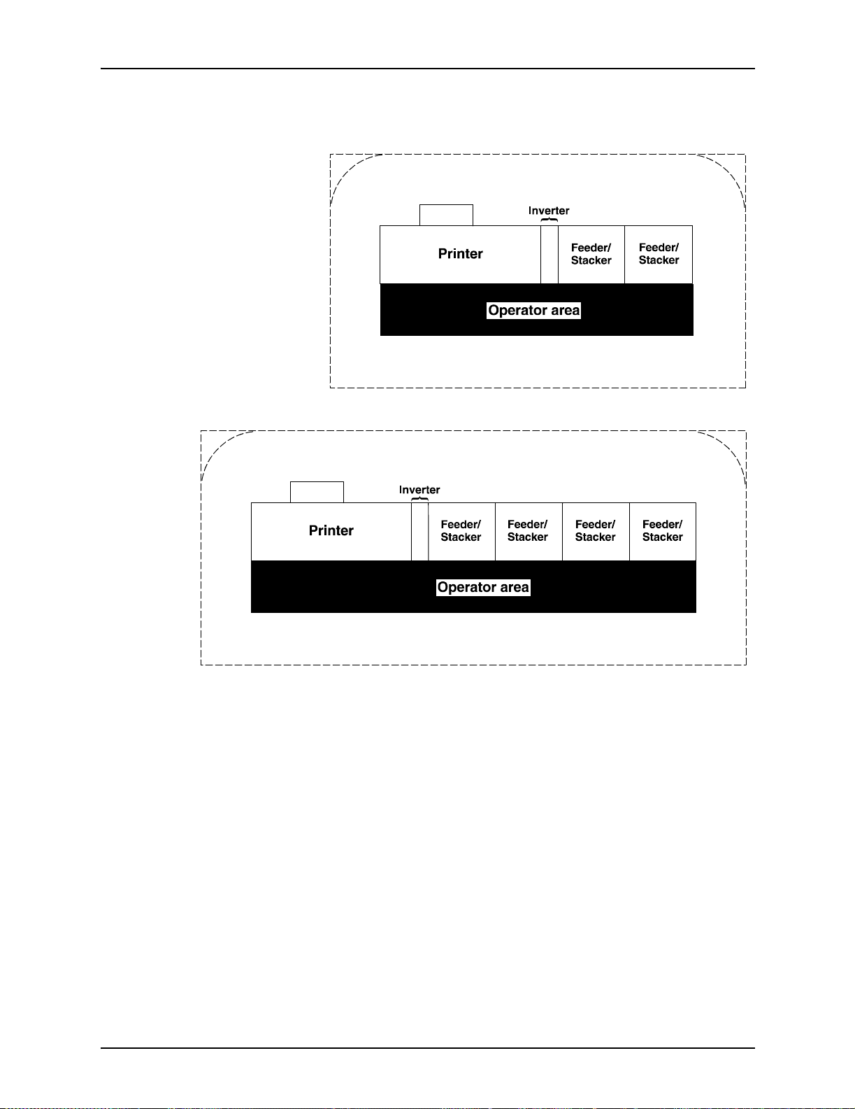
Printer requirements and specifications
Installation Planning Guide 6-29
Page 94

Printer requirements and specifications
6-30 Installation Planning Guide
Page 95

Printer requirements and specifications
Installation Planning Guide 6-31
Page 96

Printer requirements and specifications
6-32 Installation Planning Guide
Page 97

GRID PATTERN
234567891011121314
1
C
u
t
1/4 inch represen ts one foot
15 16 17 18 19 20 21 22 23 24 25 26 27 28
1
2
3
4
5
6
7
8
9
10
11
12
O
D
o
e
d
L
n
e
13
n
t
t
i
14
15
16
17
18
19
20
21
22
23
24
25
26
27
28
29
30
31
32
33
34
35
36
37
38
39
40
Page 98

Page 99
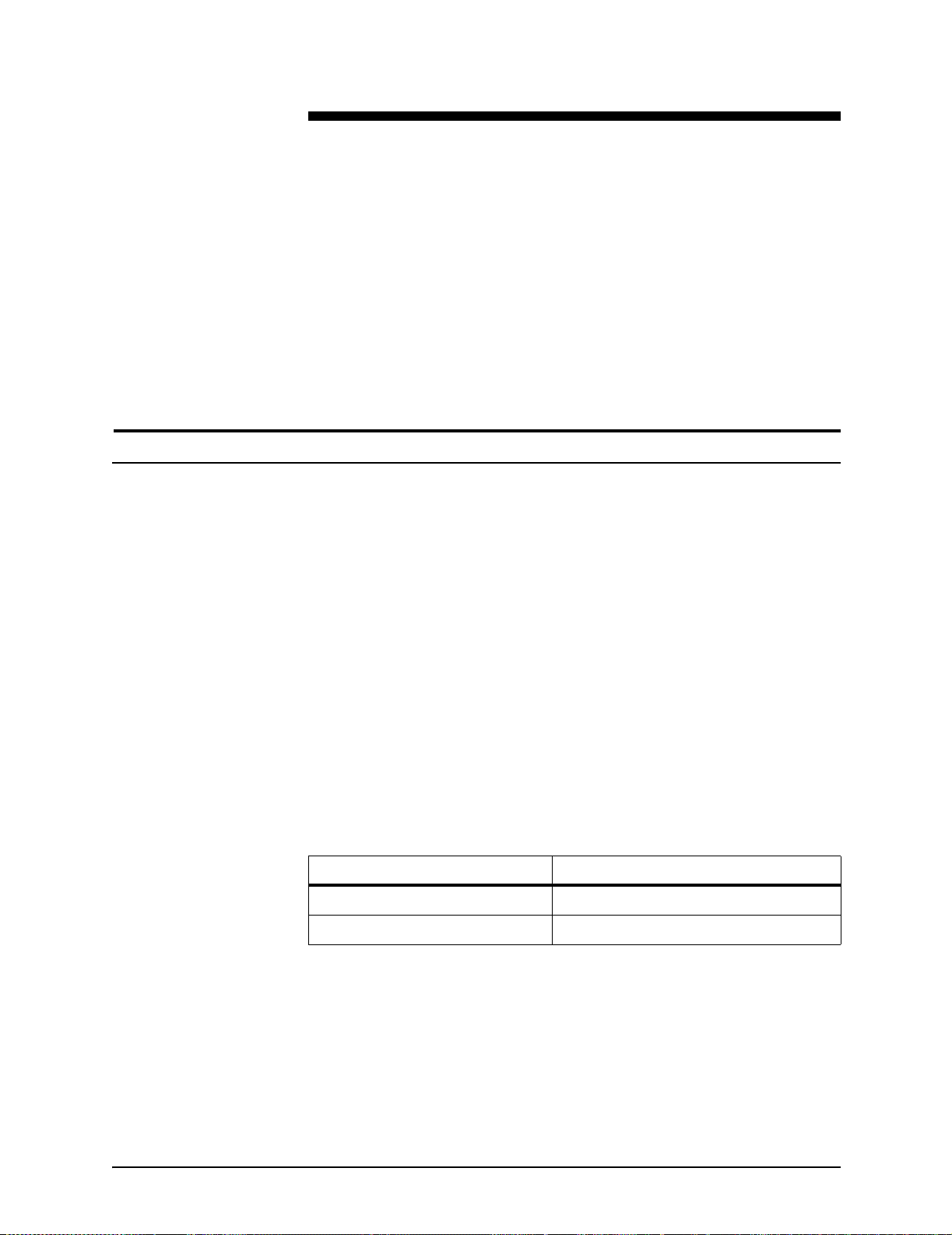
Cable lengths
7. System connections
This chapter provides cable requirements for your Xerox
DocuPrint 100/115/135/155 /1 80 EPS. It also provides
information about channel-attaching your printer. To ensure all of
your cable requirements are met, work with your Xerox
representative.
Cable lengths are important considerations in planning your
lay o ut , as co m pon en ts ca n b e se parated only up to th e le ngth of
the data inte rface cables that connect them.
Cables supplied with the printer are long enough to meet the
needs of most installations. Some of these cables are specific
lengths to confor m to engineering and safety standards.
Interface cable The printer and controller can be separated up to the length of
the interf ace cab le s that co nnect th em. The printer and controlle r
are connected by a 20 foot / 6.1 meter cable, or an optional 50
foot / 15.2 meter cable.
Power cables The printing system power cable lengths are as follows:
Table 7-1. Power cable lengths
Power cable Length
Controller 8 feet / 2.4 m
Printer 15 feet / 4.5 m
Installation Planning Guide 7-1
Page 100

System connections
Cable locations
WARNING
Using an inappropriate alternate cable may degrade the
performance of your equipment and ma y also be hazardous.
NOTE: Cable length loss must be factored in if equipment is
installed in a raised-floor environment. You should also consider
that part of the length of a cabl e is rout ed inside th e equipmen t to
connect with interior power or data receptacles.
To run the cables beneat h the flooring, y ou m ust kno w whe re the
cables enter and exit the printer. The following diagrams shows
that location marked with an X.
Figure 7-1. Cable enter/exit location (top view)
1. Back of printer area
2. Printer with feeder/stacker modules
3. Front of printer area
All power cords attach to the back of the printer. Power cord
distances from the left end of the printer (as you face it) are:
• DP 100, 115, and 135–distance from end of printer:
14 inches / 356 mm
• DP 155 and 180–distance from end of printer:
– Cord 1: 36 inches / 914 mm (with ELCI)
– Cord 2: 23 inches / 584 mm (with ELCI)
7-2 Installation Planning Guide
 Loading...