

Page 1

DocuTech 128/155/180 HighLight Color
Operator
Guide
Version 51.xx, October 2006
701P25101
Page 2

Prepared by:
Xerox Corporation
Global Knowledge and Language Services
800 Phillips Road Bldg. 845-17S
Webster, New York 14580
USA
©2006 by Xerox Corporation. All rights reserved.
Copyright protection claimed includes all forms and matters of copyrightable material and
information
now allowed by statutory judicial law or hereinafter granted, including without limitation,
material generated
from the software programs displayed on the screen such as icons, screen displays, or looks.
Printed in the United States of America.
XEROX® and all Xerox product names mentioned in this publication are trademarks of
XEROX CORPORATION.
Other company trademarks are also acknowledged.
Changes are periodically made to this document. Changes, technical inaccuracies, and typographic errors will be corrected in subsequent editions.
Page 3

Product Recycling and Disposal
If you are managing the disposal of your Xerox product, please
note that the product contains lead, mercury and other materials
whose disposal may be regulated due to environmental
considerations in cert ain countries or states. The presen ce of lead
and mercury is fully consistent with global regulations applicable
at the time that the product was placed on the market.
European Union
Some equipment may be used in both a domestic/household and
a professional/business application.
Domestic/Household Environment
Application of this symbol on your equipment is confirmation that
you should not dispose of the equipment in the normal household
waste stream.
In accordance with European legislation end of life electrical and
electronic equipment subject to disposal must be segregated from
household waste.
Private households within EU Member States may return used
electrical and electronic equipment to designated collection
facilities free of charge. Please contact your local disposal
authority for information.
In some Member States when you purchase new equipment your
local retailer may be required to take back your old equi pment free
of charge. Please ask your retailer for information.
Professional/Business Environment
Application of this symbol on your equipment is confirmation that
you must dispose of this equipment in compliance with agreed
national Procedures.
In accordance with European legislation end of life electrical and
electronic equipment subject to di sposal must be managed within
agreed procedures.
Prior to disposal please conta ct your local dealer or Xerox
representative for end of life take back information.T
DocuTech 128/155/180 HighLight Color Operator Guide i
Page 4

ii DocuTech 128/155/180 HighLight Color Operator Guide
Page 5

1 Safety notices
System safety . . . . . . . . . . . . . . . . . . . . . . . . . . . . . . . . . . . . . . . . . . . . . . . . . . . . . . . . . . . . . . . 1-1
Laser safety . . . . . . . . . . . . . . . . . . . . . . . . . . . . . . . . . . . . . . . . . . . . . . . . . . . . . . . . . . 1-1
Ozone safety . . . . . . . . . . . . . . . . . . . . . . . . . . . . . . . . . . . . . . . . . . . . . . . . . . . . . . . . . 1-2
Operation safety . . . . . . . . . . . . . . . . . . . . . . . . . . . . . . . . . . . . . . . . . . . . . . . . . . . . . . 1-2
European Union declaration of conformity . . . . . . . . . . . . . . . . . . . . . . . . . . . . . . . . . . . . . . . . . 1-3
Certification to 1999/5/EC Radio Equipment and Telecommunications Terminal Equipment Directive
1-4
Electricity at Work Regulation - UK . . . . . . . . . . . . . . . . . . . . . . . . . . . . . . . . . . . . . . . . . . . . . . 1-5
Check your understanding . . . . . . . . . . . . . . . . . . . . . . . . . . . . . . . . . . . . . . . . . . . . . . 1-6
Additional queries . . . . . . . . . . . . . . . . . . . . . . . . . . . . . . . . . . . . . . . . . . . . . . . . . . . . . . . . . . . . 1-7
2 System components
Electronic reprographics process . . . . . . . . . . . . . . . . . . . . . . . . . . . . . . . . . . . . . . . . . . . . . . . . 2-1
DocuSP controller . . . . . . . . . . . . . . . . . . . . . . . . . . . . . . . . . . . . . . . . . . . . . . . . . . . . . 2-1
DocuTech Printer . . . . . . . . . . . . . . . . . . . . . . . . . . . . . . . . . . . . . . . . . . . . . . . . . . . . . 2-1
Optional Components . . . . . . . . . . . . . . . . . . . . . . . . . . . . . . . . . . . . . . . . . . . . . . . . . . 2-2
Functional overview . . . . . . . . . . . . . . . . . . . . . . . . . . . . . . . . . . . . . . . . . . . . . . . . . . . . . . . . . . 2-2
Paper weights . . . . . . . . . . . . . . . . . . . . . . . . . . . . . . . . . . . . . . . . . . . . . . . . . . . . . . . . . . . . . . . 2-4
Special stocks . . . . . . . . . . . . . . . . . . . . . . . . . . . . . . . . . . . . . . . . . . . . . . . . . . . . . . . . 2-4
General paper characteristics . . . . . . . . . . . . . . . . . . . . . . . . . . . . . . . . . . . . . . . . . . . . 2-5
Graphical user interface overview . . . . . . . . . . . . . . . . . . . . . . . . . . . . . . . . . . . . . . . . . 2-5
System software and job flow . . . . . . . . . . . . . . . . . . . . . . . . . . . . . . . . . . . . . . . . . . . . . . . . . . . 2-6
Printer overview . . . . . . . . . . . . . . . . . . . . . . . . . . . . . . . . . . . . . . . . . . . . . . . . . . . . . . . . . . . . . 2-7
High volume printer . . . . . . . . . . . . . . . . . . . . . . . . . . . . . . . . . . . . . . . . . . . . . . . . . . . . 2-8
Production publisher . . . . . . . . . . . . . . . . . . . . . . . . . . . . . . . . . . . . . . . . . . . . . . . . . . 2-14
The System . . . . . . . . . . . . . . . . . . . . . . . . . . . . . . . . . . . . . . . . . . . . . . . . . . . . . . . . . . . . . . . 2-23
System Hardware . . . . . . . . . . . . . . . . . . . . . . . . . . . . . . . . . . . . . . . . . . . . . . . . . . . . 2-23
Paper sizing and print speed . . . . . . . . . . . . . . . . . . . . . . . . . . . . . . . . . . . . . . . . . . . . 2-26
Table of Contents
3 Routine maintenance
Cleaning and maintenance overview . . . . . . . . . . . . . . . . . . . . . . . . . . . . . . . . . . . . . . . . . . . . . 3-1
Necessary Precautions . . . . . . . . . . . . . . . . . . . . . . . . . . . . . . . . . . . . . . . . . . . . . . . . . . . . . . . 3-1
Finisher precaution . . . . . . . . . . . . . . . . . . . . . . . . . . . . . . . . . . . . . . . . . . . . . . . . . . . . 3-2
Paper . . . . . . . . . . . . . . . . . . . . . . . . . . . . . . . . . . . . . . . . . . . . . . . . . . . . . . . . . . . . . . . . . . . . . 3-3
Storing paper . . . . . . . . . . . . . . . . . . . . . . . . . . . . . . . . . . . . . . . . . . . . . . . . . . . . . . . . . 3-3
Conditioning paper . . . . . . . . . . . . . . . . . . . . . . . . . . . . . . . . . . . . . . . . . . . . . . . . . . . . 3-4
Paper curl . . . . . . . . . . . . . . . . . . . . . . . . . . . . . . . . . . . . . . . . . . . . . . . . . . . . . . . . . . . 3-5
Adding paper to tray 1 or 2 . . . . . . . . . . . . . . . . . . . . . . . . . . . . . . . . . . . . . . . . . . . . . . 3-6
Using the custom transfer assist blade . . . . . . . . . . . . . . . . . . . . . . . . . . . . . . . . . . . . . 3-7
Adjusting for paper curl . . . . . . . . . . . . . . . . . . . . . . . . . . . . . . . . . . . . . . . . . . . . . . . . . 3-9
Adjusting the decurler lever . . . . . . . . . . . . . . . . . . . . . . . . . . . . . . . . . . . . . . . . . . . . . 3-11
Maintaining the printer . . . . . . . . . . . . . . . . . . . . . . . . . . . . . . . . . . . . . . . . . . . . . . . . . . . . . . . 3-12
Replacing the black dry ink bottle . . . . . . . . . . . . . . . . . . . . . . . . . . . . . . . . . . . . . . . . 3-12
Replacing the highlight color container . . . . . . . . . . . . . . . . . . . . . . . . . . . . . . . . . . . . 3-14
Changing the highlight color Customer Changeable Units . . . . . . . . . . . . . . . . . . . . . 3-16
Adding fuser shield . . . . . . . . . . . . . . . . . . . . . . . . . . . . . . . . . . . . . . . . . . . . . . . . . . . 3-23
DocuTech 128/155/180 HighLight Color Operator Guide
iii
Page 6

Waste containers . . . . . . . . . . . . . . . . . . . . . . . . . . . . . . . . . . . . . . . . . . . . . . . . . . . . 3-27
Wire Module Removal and Replacement . . . . . . . . . . . . . . . . . . . . . . . . . . . . . . . . . . 3-30
Cleaning the system and its components . . . . . . . . . . . . . . . . . . . . . . . . . . . . . . . . . . . . . . . . . 3-32
Cleaning the 18/36-track cartridge tape drive . . . . . . . . . . . . . . . . . . . . . . . . . . . . . . . 3-32
Cleaning the 26-track cartridge tape drive . . . . . . . . . . . . . . . . . . . . . . . . . . . . . . . . . 3-33
Cleaning the DVD drive . . . . . . . . . . . . . . . . . . . . . . . . . . . . . . . . . . . . . . . . . . . . . . . . 3-33
Cleaning the diskette drive . . . . . . . . . . . . . . . . . . . . . . . . . . . . . . . . . . . . . . . . . . . . . 3-33
Cleaning the sensors and the reflecting surfaces . . . . . . . . . . . . . . . . . . . . . . . . . . . . 3-34
Cleaning the Q850 and Q861 sensor . . . . . . . . . . . . . . . . . . . . . . . . . . . . . . . . . . . . . 3-34
Cleaning the Q1011/1009 sensor and mirror . . . . . . . . . . . . . . . . . . . . . . . . . . . . . . . 3-36
Cleaning the Q1106 and Q1166 sensors . . . . . . . . . . . . . . . . . . . . . . . . . . . . . . . . . . 3-36
Cleaning the Q1107 sensor . . . . . . . . . . . . . . . . . . . . . . . . . . . . . . . . . . . . . . . . . . . . 3-37
Cleaning the Q1164 sensor . . . . . . . . . . . . . . . . . . . . . . . . . . . . . . . . . . . . . . . . . . . . 3-38
Cleaning the display . . . . . . . . . . . . . . . . . . . . . . . . . . . . . . . . . . . . . . . . . . . . . . . . . . 3-39
Cleaning the exterior surfaces of the system . . . . . . . . . . . . . . . . . . . . . . . . . . . . . . . 3-39
Clearing or cleaning the finisher sensors . . . . . . . . . . . . . . . . . . . . . . . . . . . . . . . . . . 3-40
Clearing the Q1201 sensor . . . . . . . . . . . . . . . . . . . . . . . . . . . . . . . . . . . . . . . . . . . . . 3-40
Clearing the Q1202 and Q1203 sensors . . . . . . . . . . . . . . . . . . . . . . . . . . . . . . . . . . . 3-41
Cleaning the Q1222 and Q1210 sensors . . . . . . . . . . . . . . . . . . . . . . . . . . . . . . . . . . 3-43
Clearing the Q1205, Q1206, and Q1207 sensors . . . . . . . . . . . . . . . . . . . . . . . . . . . . 3-44
Clearing the Q1213 sensor . . . . . . . . . . . . . . . . . . . . . . . . . . . . . . . . . . . . . . . . . . . . . 3-45
Clearing the Q1221, Q1218, and Q1227 sensors . . . . . . . . . . . . . . . . . . . . . . . . . . . . 3-46
Cleaning the binder . . . . . . . . . . . . . . . . . . . . . . . . . . . . . . . . . . . . . . . . . . . . . . . . . . . 3-47
Cleaning the binder tape guides . . . . . . . . . . . . . . . . . . . . . . . . . . . . . . . . . . . . . . . . . 3-49
Cleaning the binder platen . . . . . . . . . . . . . . . . . . . . . . . . . . . . . . . . . . . . . . . . . . . . . 3-49
Cleaning the flappers . . . . . . . . . . . . . . . . . . . . . . . . . . . . . . . . . . . . . . . . . . . . . . . . . 3-50
Cleaning the calipers . . . . . . . . . . . . . . . . . . . . . . . . . . . . . . . . . . . . . . . . . . . . . . . . . . 3-51
Closing the binder . . . . . . . . . . . . . . . . . . . . . . . . . . . . . . . . . . . . . . . . . . . . . . . . . . . . 3-52
Replacing the stitcher spool A . . . . . . . . . . . . . . . . . . . . . . . . . . . . . . . . . . . . . . . . . . . 3-52
Storing the binder tape reels . . . . . . . . . . . . . . . . . . . . . . . . . . . . . . . . . . . . . . . . . . . . 3-59
Replacing the binder tape reel . . . . . . . . . . . . . . . . . . . . . . . . . . . . . . . . . . . . . . . . . . 3-61
Adjusting the binder tape registration . . . . . . . . . . . . . . . . . . . . . . . . . . . . . . . . . . . . . 3-65
4 Problem Solving
How problems are displayed . . . . . . . . . . . . . . . . . . . . . . . . . . . . . . . . . . . . . . . . . . . . . . . . . . . 4-1
Printer faults and fault windows . . . . . . . . . . . . . . . . . . . . . . . . . . . . . . . . . . . . . . . . . . . . . . . . . 4-1
When a fault occurs . . . . . . . . . . . . . . . . . . . . . . . . . . . . . . . . . . . . . . . . . . . . . . . . . . . 4-2
Resolving a processor problem . . . . . . . . . . . . . . . . . . . . . . . . . . . . . . . . . . . . . . . . . . . . . . . . . 4-2
Solving print quality problems . . . . . . . . . . . . . . . . . . . . . . . . . . . . . . . . . . . . . . . . . . . . . . . . . . 4-6
Clearing paper jams . . . . . . . . . . . . . . . . . . . . . . . . . . . . . . . . . . . . . . . . . . . . . . . . . . . 4-6
Incorrect paper size message . . . . . . . . . . . . . . . . . . . . . . . . . . . . . . . . . . . . . . . . . . . 4-22
Interposer problems . . . . . . . . . . . . . . . . . . . . . . . . . . . . . . . . . . . . . . . . . . . . . . . . . . 4-23
Finisher problems . . . . . . . . . . . . . . . . . . . . . . . . . . . . . . . . . . . . . . . . . . . . . . . . . . . . 4-23
Binder tape fault . . . . . . . . . . . . . . . . . . . . . . . . . . . . . . . . . . . . . . . . . . . . . . . . . . . . . 4-25
Stitcher spool A fault . . . . . . . . . . . . . . . . . . . . . . . . . . . . . . . . . . . . . . . . . . . . . . . . . . 4-26
Checking paper curl . . . . . . . . . . . . . . . . . . . . . . . . . . . . . . . . . . . . . . . . . . . . . . . . . . 4-30
Customer Support Center . . . . . . . . . . . . . . . . . . . . . . . . . . . . . . . . . . . . . . . . . . . . . . . . . . . . 4-30
5 Technical information
DocuTech printer specifications . . . . . . . . . . . . . . . . . . . . . . . . . . . . . . . . . . . . . . . . . . . . . . . . . 5-1
Printer rates . . . . . . . . . . . . . . . . . . . . . . . . . . . . . . . . . . . . . . . . . . . . . . . . . . . . . . . . . . 5-1
Paper tray capacities . . . . . . . . . . . . . . . . . . . . . . . . . . . . . . . . . . . . . . . . . . . . . . . . . . . 5-1
Additional paper capacities . . . . . . . . . . . . . . . . . . . . . . . . . . . . . . . . . . . . . . . . . . . . . . 5-3
Printer satisfaction guides . . . . . . . . . . . . . . . . . . . . . . . . . . . . . . . . . . . . . . . . . . . . . . . . . . . . . 5-4
iv DocuTech 128/155/180 HighLight Color Operator Guide
Page 7

Stock satisfaction guides . . . . . . . . . . . . . . . . . . . . . . . . . . . . . . . . . . . . . . . . . . . . . . . . 5-5
Using non-standard stock . . . . . . . . . . . . . . . . . . . . . . . . . . . . . . . . . . . . . . . . . . . . . . 5-10
Paper stock rotation . . . . . . . . . . . . . . . . . . . . . . . . . . . . . . . . . . . . . . . . . . . . . . . . . . 5-11
Finisher satisfaction guides . . . . . . . . . . . . . . . . . . . . . . . . . . . . . . . . . . . . . . . . . . . . . 5-14
6 Service and supplies
Xerox support services . . . . . . . . . . . . . . . . . . . . . . . . . . . . . . . . . . . . . . . . . . . . . . . . . . . . . . . . 6-1
Customer support . . . . . . . . . . . . . . . . . . . . . . . . . . . . . . . . . . . . . . . . . . . . . . . . . . . . . 6-1
Operator training . . . . . . . . . . . . . . . . . . . . . . . . . . . . . . . . . . . . . . . . . . . . . . . . . . . . . . 6-2
Supplies service . . . . . . . . . . . . . . . . . . . . . . . . . . . . . . . . . . . . . . . . . . . . . . . . . . . . . . 6-2
Routine maintenance . . . . . . . . . . . . . . . . . . . . . . . . . . . . . . . . . . . . . . . . . . . . . . . . . . 6-4
Meter reading and reporting . . . . . . . . . . . . . . . . . . . . . . . . . . . . . . . . . . . . . . . . . . . . . 6-4
Consumable supplies table . . . . . . . . . . . . . . . . . . . . . . . . . . . . . . . . . . . . . . . . . . . . . . 6-4
DocuTech 128/155/180 HighLight Color Operator Guide v
Page 8

vi DocuTech 128/155/180 HighLight Color Operator Guide
Page 9

About this guide
Introduction
The DocuTech 128/155/180 HLC Operator Guide is one of a
number of publications that make up the Xerox Document
Services Platform Series.
The guide is intended for Xerox DocuTech 128/155/180 HLC
operators whose job consists of the routine operation of this
printing system: operating each of the system components,
running print jobs, solving simple system probl ems, and
performing basic maintenance tasks, such as replenishing printer
supplies .
If you are a lead operato r, or your job i nvolves some progr amming
or systems administration tasks, as well as operating the
DocuTech 128/155/180 HLC system, use the on-line help system
and the other documents in the Xerox Document Services
Platform Series to supplement the i nformation in this guide.
Contents
Before using this guide, become familiar with its contents and
conventions.
WARNING: Both power cords wi th the printer must be
disconnected from the printer in order to completely power down
the machine.
This section lists the contents of this guide.
• “System components” contains an explanation of each of the
system components.
• “Routine maintenance” describes the routine activities you
perform to maintain the reliability and productivity of your
printer.
• “Problem solving” describes how the system informs you of
problems. When you know there is a system problem, you can
take measures suggested by the system to correct the
problem. You can also use the problem and solution tables in
this section to resolve recurri ng problems.
DocuTech 128/155/180 HighLight Color Operator Guide vii
Page 10

Introduction
Conventions
• “Technical information” contains the hardware and software
capacity guidelines for the DocuTech 128/155/180 HLC
systems.
• “Supplies” lists the supplies that you might want to keep in
stock, and the information you need to order them.
This guide uses the following conventions :
• All caps and angle brackets–Within procedures, the names of
keys are shown in all caps within angle bra cket s (f or example,
press <RETURN>).
• Angle brackets–Variable information, or the position of a
specified argument in the command syntax, appears in angle
brackets (for example, List Fonts <Pattern>).
• Bold–Within procedures, text and numbers that you enter are
shown in bold (for example, enter boot).
• Enter–Within procedures, the two-step process of keying in
data and pressing <RETURN> (for example, enter y).
• Italics–Document and library names are shown in italics (for
example, the Xerox Document Services Platf orm Series
System Guide).
• Square brackets–Names of options you select are shown in
square brackets (for exampl e, Select [Exit]).
• Quotes–Keywords you can enter as arguments appear in
quotes (for example, “US Letter”).
• Vertical bars–Alternatives to spec ified arguments are
separated by vertic al bar s (for example , -pdl < p s | hpp cl | asci i
| tiff>).
NOTE: Notes contain important supplemental information
pertaining to the task that you should read.
CAUTION: Cautions alert you to an action that could damage
hardware, software, or your data.
WARNING: Warnings alert you to conditions that may affect the
safety of people.
viii DocuTech 128/155/180 HighLight Color Operator Guide
Page 11

System safety
Laser safety
1 Safety notices
It is your responsibility to ensure your Xerox equipment is safe at
all times. This section includes equi pment safety notices rel ated to
laser safety, ozone safety, and operation safety.
WARNING: Use of controls or adjustments, or performances
other than specified herein, may result in hazardous r adiation
exposure.
The Xerox DocuTech 128/155/180 HLC models are certified to
comply with laser performance standards set by the U.S.
Department of Health, Education, and Welfare as Class 1 laser
products. This is a class of laser products that does not emit
hazardous radiation. This i s possible onl y because the l aser beam
is totally enclosed duri ng all modes of customer operation.
When performing operator functions, laser warning l abels may be
visible. These labels are to alert and remind the se rvice
representative and are placed on or near p anels or shields which
require a tool for removal.
THE PANELS TO WHICH THESE LABELS ARE FIXED OR
NEAR ARE NOT TO BE REMOVED BY ANYONE OTHER THAN
AUTHORIZED TRAINED PERSONNEL.
Figure 1-1. Laser warning label
DocuTech 128/155/180 HighLight Color Operator Guide 1-1
Page 12

Safety notices
Ozone safety
Operation safety
This product produces ozone during normal oper ation. The ozone
produced is dependent on copy volume and is heavier than air.
Providing the proper e nvironment al p arameters as specif ied in t he
Xerox installation instructions ensures that concentration levels
meet safe limits.
Your Xerox equipment and supplies have been designed and
tested to meet strict safety requirements. These include safety
agency examination and approval, and compliance to est ablished
environmental standards.
Attention to the following notes ensures the cont inued safe
operation of your equipment.
• The system is heavy. Ensure that the floor is level and strong
enough to support the weight of the system.
• Do not place the system near a heat source.
• To move the system, call a Service Representative.
• Do not use an extension cord. Always connect the system
power cable to a properly grounded power source recept acle.
If in doubt, have the receptacle checked by a qualified
electrician.
• Do not use an adaptor plug to connect the system to an
electrical outlet that lacks a ground connection terminal.
WARNING: Improper connection of the equipment grounding
conductor can result in risk of electrical shock.
• Do not locate the system where people may walk on the
system power cable. Do not place objects on the system
power cable.
• Never override or disable electrical or mec hanical interlocks.
WARNING: Do not push objects into slots and openings on the
system. Making contact with a volt age p oint or shorting out a part
could result in fire or electrical shock.
• If you hear unusual noises or smell strange odors, switch off
the system power immediately. Disconnect the system power
cables from the electrical outlet and call a service
representative.
• Do not place containers of coffee or other liquids on the
system.
• Switch off the sy stem power , disco nnect the power cables, a nd
call a service representative when any of the following
conditions occur:
1-2 DocuTech 128/1 55/180 High Light Col or Operat or Guide
Page 13

Safety notices
– The power cable is damaged or frayed.
– Liquid is spilled into the system.
– The system is exposed to water.
– Any part of the system is damaged.
• Always use materials and supplies specifically designed for
your Xerox equipment. Use of unsuit able materials may result
in poor performance and can possibly create a hazardous
situation.
• Never attempt any maintenance functi on that is not specifica lly
described in this Operator Guide.
• Never remove any covers or guards that are fastened with
screws. There are no operator-serviceable areas within these
covers.
• Never use supplies or cleaning materials for other than their
intended purposes. Keep all materials out of the reach of
children.
European Union declaration of conformity
Approvals and
certification
The CE marking applied to this product symbolizes Xerox Europe
Declaration of Conformity with the following applicable Directives
of the European Union as of the dates indicated below.
• January 1, 1995: Council Directive 73/23/EEC amended by
Council Directive 93/68/EC, approximation of the laws of the
member states related to low voltage equipment.
• January 1, 1996: Council Directive 89/336/ EC, a pprox imation
of the laws of the member Stated related to electromagnetic
compatibility.
• March 9, 1999: Council Directive 1995/5/EC on radio
equipment and telecommunications terminal equi pmen t and
the mutual recognition of their conformity.
A full declaration, defining the relevant directives and referenced
standards can be obtained from your Xerox Europe
representative.
WARNING: Changes or modif ication to this equipment not
specifically approved by Xerox Europe may void user’s authority
to operate the equipment. Shielded cables mus t be used wit h this
equipment to maintain compliance with the EMC Directi ve (89/
336/EEC).
WARNING: Thi s is a Clas s A produ ct. In a do mesti c envir onment
this product may cause radio interference in which case the user
may be required to take adequate measures.
DocuTech 128/155/180 HighLight Color Operator Guide 1- 3
Page 14

Safety notices
WARNING: This sys tem is cer ti fied manufactured and tested in
compliance with strict safety and radio fr equency interference
regulations. Any unauthorized alteration which includes the
addition of new functions or the connections of external devices
may impact this certification. Please contact your local Xerox
Europe representative for a list of approved accessories.
Shielded cables must be used with this equipment to maintain
compliance with the EMC Directive (89/336/ EEC).
This equipment is not primarily intended for use in a domestic
environment.
WARNING: In order to allow this equipment to operate in
proximity to industrial , scientific, and medical (ISM) equipment, the
external radiation from the ISM equipment may have to be limited
or special mitigation measures taken.
Certification to 1999/5/EC Radio Equipment and
Telecommunications Terminal Equipment Directive
This Xerox product has been self-certified by Xerox for panEuropean single terminal connection to the analogue public
switched telephone network (PSTN) in accordance with Directive
1999/5/EC.
The product has been designed to work with the national PSTNs
and compatibles PBXs of the following countries:
•Austria
• Belgium
• Denmark
• France
• Finland
• Germany
•Greece
• Iceland
• Ireland
•Italy
• Luxembourg
• Netherlands
•Norway
• Portugal
•Spain
• Sweden
• Switzerland
• United Kingdom
1-4 DocuTech 128/1 55/180 High Light Col or Operat or Guide
Page 15

Safety notices
In the event of problems, you should contact your local Xerox
representative in the first instance.
The product has been tested to and is complaint with TBR21, a
specification for termi nal equi pment fo r use on analogue swit ched
telephone networks in the European Economic Area.
The product may be configured to be compatible with other
country networks. Please contact your Xerox representative if it
needs to be reconnected to another country’s network.
There are no user-adjustable settings in the product.
NOTE: Although this product can use either loop disconnect
(pulse) or DTMF (tone) signalling, it is recommended that it is set
to use DTMF signalling. DTMF signalling provides reliable and
faster call set-up.
Modification, connection to ext ernal control soft ware or to ext ernal
control apparatus not authorized by Xerox, will invalidate it s
certification.
Electricity at Work Regulation - UK
The Electricity at Work Regula ti on applies only to England and
Wales.
The Regulation
The Electricity at Work Regula tion 1989 came into force in
England and Wales on 1 April 1990. This 1989 Regulation places
a duty on all employers and self employed persons to ensure the
electrical systems in their premises are constructed, maintained
and operated in such a manner as to prevent, so far as reasonably
practical, danger. This includes ensuring all electrical equipment
connected to such electrical systems are safely constructed,
maintained and operated.
All Xerox equipment have been designed to exacting safety
standards. They have all undergone a variety of stringent safety
tests including earth bond, insul a tion resistance and electrical
strength tests. Xero x Europe ma nufacturing plants have been
awarded ISO 9000 quality certification and are subj ect to regular
audits by the British Standards I nstitution or equivalent national
standards body.
Xerox equipment which has been properly and regularly serviced
and maintained should not have to undergo additional specific
safety tests pursuant to the 1989 Regulation. Customers wishing
to complete safety testing should contact Xerox Europe Technical
Centre for advice prior to any test implementation.
Xerox equipment should, however, be properly and regularly
serviced and maintained at all ti mes.
DocuTech 128/155/180 HighLight Color Operator Guide 1- 5
Page 16

Safety notices
Check your understanding
Please review the questions and answers that follow to ensure
that you understand the Electricity at Work Regulation in England
and Wales.
Question What is the Electricity at Work Regulation?
Answer The Electricity at Work Regulation 1989 came into force in
England and Wales on 1 April 1990. This 1989 Regulation places
a duty on all employers and self-employed persons to ensure
the electrical systems in their premises are constructed,
maintained and operated in such a manner as to pr event, so far as
reasonably practicable, danger. This includes ensuring all
electrical products conn ected to such ele ctrical syst ems are safely
constructed, maintained and oper ated.
Question Does Xerox Europe comply with the Electricity at Work
Regulation?
Answer The regulation places a duty on all employers and self
employed persons to ensure the electri cal systems in their
premises are, effectively safe.
This regulation does not impose on, amongst others,
manufacturers or suppliers of such electrical systems.
However , rest assured that all Xerox equipment which Xerox
Europe and its authorized distributors supply to customers
conforms with all the relevant safety legislation and standards.
Question Is Xerox equipment safe?
Answer All Xerox equipment supplied by Xerox Europe and their
authorized distributors conforms to all relevant safety legislation
and standards.
Question Is the Xerox equipment in my premises safe?
Answer All Xerox equipment supplied by Xerox Europe and their
authorized distributors conforms to all relevant safety legislation
and standards. However, like all electrical equipment, they have to
be regularly serviced and maintai ned by competent persons.
Xerox Europe Customer Service Engineers ensure Xerox
equipment is serviced and maintained to exacting Xerox safety
standards. If you would like your Xerox equipment to be serviced
and maintained to such high standards, please contact your local
Xerox Europe Customer Service Organization. They will be
pleased to assist you.
Question Does the Xerox equipment in my premises comply with the
Electricity at Work Regulations?
Answer All employers and self-employed persons must ensure that the
electrical systems in their premises are safe. This will include
ensuring Xerox equipment in such premises is safe.
Xerox Europe’s Product Safety function has prepared a guide
which contains a list of test s wh ich may be completed by your
Xerox Europe Customer Service Organization. THESE TESTS
1-6 DocuTech 128/1 55/180 High Light Col or Operat or Guide
Page 17

Safety notices
MUST BE CARRIED OUT ONL Y BY PERSONS WHO POSSESS
THE RELEVANT SKILL, KNOWLEDGE AND EXPERIENCE TO
CARRY OUT SUCH TESTS.
Please contact the Xerox Europe Customer Service Organizat ion
for further information.
THE USE OF INAPPROPRIATE TEST PROCEDURES AND
TEST EQUIPMENT MAY PROVIDE MISLEADING RESULTS
AND MAY CAUSE DEATH, PERSONAL INJURY AND/OR
DAMAGE TO PROPERTY.
Question I would like to carry out my own safety tests on the Xerox
equipment in my premises.
Answer You may, of course, re quest such te st s as you deem neces sary to
satisfy yourself that your Xerox equipment is safe. Your Xerox
Europe Customer Support will be pleased to advise you on such
testing.
Question I require records of all tests.
Answer After safety testing, your Xerox Europe Customer Service
Engineer will provide you with a certificate whic h details the r esults
of all tests completed.
Additional queries
In the event of any defect being noted, the Xerox equipment will
be switched off and disconnected fr om the suppl y unti l the defect
has been corrected. You will be advised of such action to enable
such defects to be corrected.
Please contact the Xerox Europe Technical Centre or your
authorized Xerox represent ative if you hav e any queries regardi ng
the information provided in this document.
DocuTech 128/155/180 HighLight Color Operator Guide 1- 7
Page 18

Safety notices
1-8 DocuTech 128/1 55/180 High Light Col or Operat or Guide
Page 19

2 System component s
The Xerox DocuTech HLC printers are electronic reprographics
systems. They are high volume printers available in multiple
configurations. These versatile, high performance printing
systems enable personal computers and o ther network-connected
devices (such as workstations and graphic scanners) to produce
documents incorporating graphi cs, forms, logos, signatures, and
fonts.
Electronic reprographics process
The Xerox DocuTech HLC system consists of a DocuSP control ler
and a DocuTech printer.
DocuSP controller
DocuTech Printer
The DocuSP controller accepts electronic print input created by
client software in ASCII, TIFF, HP PCL, PostScript, PPML, LCDS,
IPDS, VIPP or PDF format. This print input is passed on to the
system through a network connection. The DocuSP software
performs the necessary data conve rsi on, creating an electronic
file which is stored temporarily in a print queue on the DocuSP
controller. This electronic image is then passed directly on to the
printer for production.
The DocuTech 180 prints up to 180 prints per minute using 8.5 x
11 inch/A4 (216 x 279 mm) stock.
The DocuTech 155 prints up to 155 prints per minute using 8.5 x
11 inch/A4 (216 x 279 mm) stock.
The DocuTech 128 prints up to 128 prints per minute using 8.5 x
11 inch/A4 (216 x 279 mm) stock.
NOTE: The DocuTech HLC prints in black and white plus one
highlight color.
NOTE: Prints per minute vary, depending on paper size, for all
printers.
DocuTech 128/155/180 HighLight Color Operator Guide 2-1
Page 20

System components
Optional Components
Functional overview
• Inverter Feeder/Stacker and up to 3 Feeder/Stackers
• 2-Tray Inte rposer and Finisher (Production publisher
configuration)
NOTE: The initial release of the Production publisher (Interposer
and Finisher) configuration is 180 PPM only and does not suppor t
LCDS & IPDS.
The Xerox DocuTech HLC prints high quality, high resolution
documents in simplex or duplex mode at high product ion speeds,
from LCDS, PostScript, PCL, and other data strea ms. The system
can switch between printing different types of data streams
without a need for rebooting or reconfiguring software.
The printer supports:
• Duplex printing
• Media handling of multiple weights, sizes, and types
• Optional modules for enhanced finishing and output to thirdparty finishing devices
• Optional enabling of a third-party roll feeder
• Depending on your configuration: optional hi gh-capacity
feeder/stacker modules, whi ch provide additional feeder trays
and output bins
• Depending on your configuration: Interposer/Finisher/Binder
• High resolution of LCDS*, PostScript, and PCL data streams
(shown in the following table)
NOTE: *The initial release of the Pr oduction publ isher (Interposer
and Finisher) configuration is 180 PPM only and does not suppor t
LCDS & IPDS.
2-2 DocuTech 128/1 55/180 High Light Col or Operat or Guide
Page 21

System components
Table 1. Data stream resolution
Data stream Input resolution
Print resolution: DP128/155/180 HLC
LCDS 300 by 300 dpi 600 x 2400 dpi (High volume printer only)
PostScript and PCL 300 by 300 dpi or 600
by 600 dpi
Data formats supported
The Xerox DocuTech 128/155/180 HLC can print the following
data formats:
• ASCII
• LCDS*
• IPDS*
• PCL
• PDF
•PostScript
•TIFF
• PPML
NOTE: * Not supported on the Production pub li sher conf igurat i on
at this time.
The system prints LCDS data from a mainframe host compu ter,
emulating an IBM 4245 or 3211 page printer. The printing system
can receive data over a channel through bus and tag cables, and
through the Socket Gateway or lpr using TCP/IP protocol.
600 x 2400 dpi (High volume printer)
600 x 600 dpi (Production publisher)
The system also prints PostScript and PCL data submitted over a
network (Ethernet or AppleTalk) from a variety of clients:
• PCs (Windows and Windows NT)
• Sun workstations (UNIX)
• UNIX command line clients: lpr (incl uding lp) and Xerox
Command Line Client (CLC)
• NetWare Q-Server through a Novell print server (bindery
mode only)
• Apple Macintosh workstations
DocuTech 128/155/180 HighLight Color Operator Guide 2- 3
Page 22

System components
Paper weights
Stock specifications
The success of any print run depends on proper selection, care,
and handling of the paper or other stock that is used. It is very
important to select, sto re, condit ion, and l oad print medi a properly
in order to keep your printer running at optimum efficiency.
The printer functions best and produces the best prin t quality
when using stocks that have the correct:
•Size
• Weight
•Type
• Color
For more comprehensive information on paper stocks for Xerox
printers, refer to Helpful facts about paper, 721P82493.
Special stocks
The DT 128/155/180 HLC supports the following range of paper
weights:16–110 pound / 60–200 gsm
Other paper weights should not be used.
The equivalent grams per square meter of 20 pound paper is
actually 75 gsm. However , there is no s tandard 75 gsm paper. The
available stock that is closest in weight to 20 pound paper is 80
gsm.
The following special stocks can be used with the DocuTech 128/
155/180 HLC:
• Labels: Must be the type designed fo r high-speed pr inter s and
must meet the specifications described in the secti on above.
Loading instructions are print ed o n all paper trays.
• Transparencies: Must be the type designed for high-speed
printers and must meet the specifications described in the
section above. Loading instructions are pr inted on all paper
trays.
• Colored paper: Available in a variety of colors, colored paper
has many uses, including calling attentio n to certain printed
material, separating special sections, or dividing chapters of a
report.
• Preprinted paper: May be letter head, forms, or logos. ( Refer to
the “Helpful Facts about Paper” guide to verify that the
preprinting inks used on your stock are t he ki nd formula ted f or
use in laser prin te r s .)
2-4 DocuTech 128/1 55/180 High Light Col or Operat or Guide
Page 23

• Predrilled paper: Has holes for use in binders or binder rings.
Before loading predrilled paper, fan it to remove any loose
plugs that could cause paper jams.
• Perforated paper: Have been pi erced with one or more rows of
holes to permit easy tearing or separating into sections. Read
and follow the instructions on the ream packaging.
• Precut or full tabs
• Carbonless paper: Is paper that is treated or coated to
produce an image under pressure (without the use of carbon
paper). After opening, close and seal the original ream
wrapper to store. Do not leave in paper trays overnight. Read
and follow the instructions on the ream packaging.
General paper characteristics
When selecting paper, look for the following :
• Low moisture content (a paper to moisture ratio below 5.7
percent). Paper with higher moisture content may curl and
jam.
System components
• Smooth surface
• Moisture resistant wrapping
• No defects such as bent edges or uneven surfaces
• Grain runs parallel with the long side of paper
Graphical user interface overview
The graphical user i nterface (GUI) on the control ler enables yo u to
interact with the printing sys tem. It contains windows, icons, and
menus through which you can issue commands and perform
operation and system administration tasks.
When the workstation controller is powered on and booted, the
DocuSP Print Services main menu displays on the controller
screen.
DocuTech 128/155/180 HighLight Color Operator Guide 2- 5
Page 24
System components
System software and job flow
This section describes how the system softwar e processes are
used as a typical job flows through the system.
NOTE: There are no job flow differences between the High
volume printer and the Production publisher configurations.
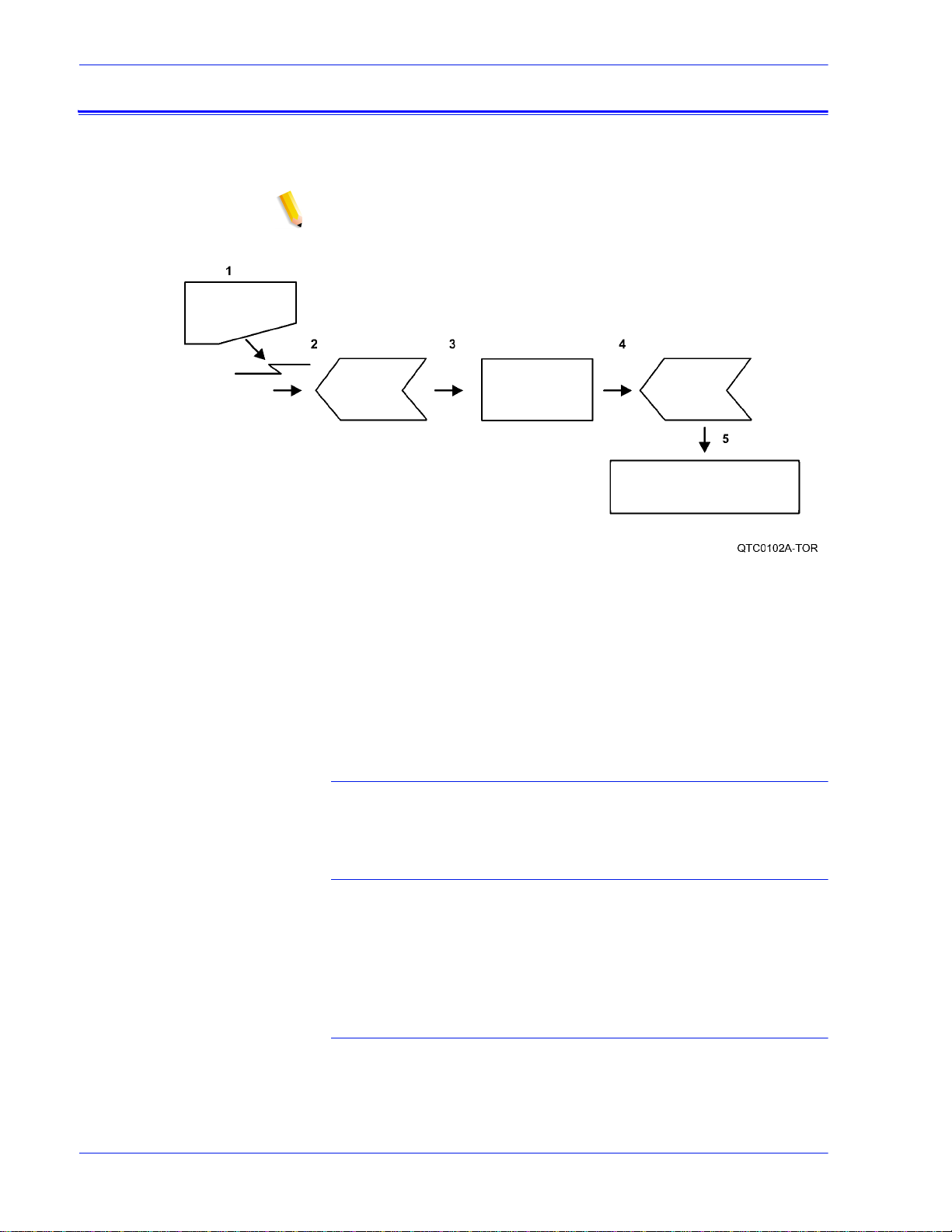
Figure 2-1. Job flow
1. Job
2. Input Queue
3. Decomposer
4. Output queue
5. Printer
Job
The job and the job ticket (if applicable) are recei ved from the
network by one of the protocol gateways.
Input queue
The Job Pool Manager (JPM) process transfers the job into the
input queue. The virtual printer name and job attr ibutes are
attached to the job. The job remains i n the Input Queue until i t can
be printed; for example, “held” and “fau lted” jobs reside in the
input queue.
Decomposer
The Job Chooser reconciles the job attributes with the virtual
printer attributes. Once the job is ready for print, the Job Chooser
gives the job to the appropriate decomposer, PostScript or PCL.
2-6 DocuTech 128/1 55/180 High Light Col or Operat or Guide
Page 25

System components
Output queue
After decomposition, the job is stored in the output queue.
Printer
The marker transfers the job from the Output Queue to the pr inter.
After the job has successfully printed, it is removed from the
Output Queue and also from the Input Queue.
The printing process and job flow is different for PostScript, PCL,
TIFF, ASCII, PDF jobs (that is, non-LCDS jobs) and for LCDS
jobs.
PostScript, PCL,
TIFF, ASCII, IPDS,
and PDF jobs
Printer overview
When the job is sent from the application for printing, a print data
file is created. This file becomes the job that is submitted to the
printer for printing. The prin t data file and the job request are
submitted to the selected queue. Jobs are processed by priority
within the designated queue once the job reaches t he queue from
a given application.
NOTE: IPDS and LCDS are not supported on the Production
publisher configuration at this time.
The printer receives data from the controller and prints the
document according to the print options s pecified by the us er. The
printer also stacks and collates the printed output.
The printer system is available in two configurations:
1. High volume printer with invert er feeder/stacker and up to
three feeder/stackers
2. Production publisher with a 2-tray interposer and finisher
DocuTech 128/155/180 HighLight Color Operator Guide 2- 7
Page 26
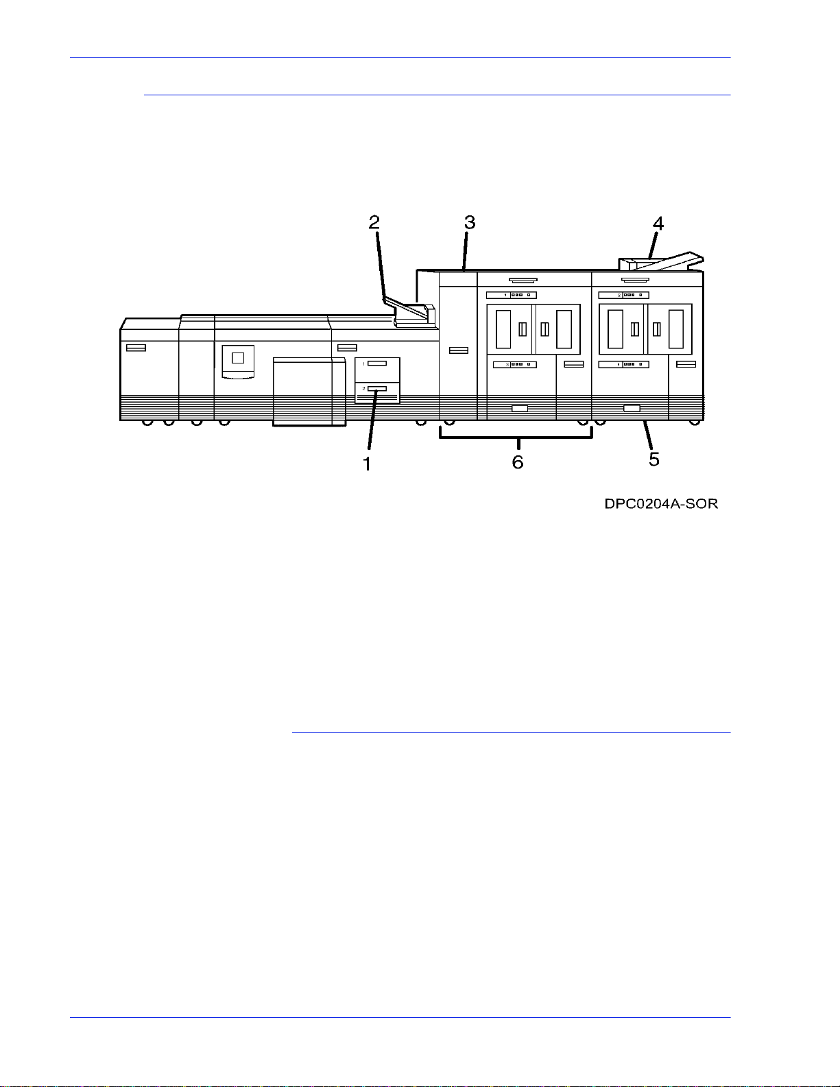
System components
High volume printer
The components, special features, and configurations of the
Xerox DocuTech 128/155/180 HLC printer are shown in the
following figures.
Figure 2-2. Printer with inverter feeder/stacker + feeder/
stacker (standard base configuration)
1. Feeder tray
2. Sample tray
3. Attention light
4. Purge tray
5. Feeder/stacker modules
6. Inverter feeder/stacker
Feeder/paper tray (High volume printer)
Multiple feeder/paper trays can be configured to feed paper for
jobs in the most effective manner. For example, the trays can
provide nonstop printing of a complex job that requires many
paper stocks, or only a few stocks, by using the trays continuous
loading capability. A different input tray can also be selected for
each copy of a specific page in a print job, for exa mple, to prov ide
different paper colors for specific pages.
The printing system may have up to six feeder/paper trays: two
processor feeder trays and two to four high-capacity trays. Four
addressable input trays are standard with the system, and two
additional high-capacity trays are optional.
2-8 DocuTech 128/1 55/180 High Light Col or Operat or Guide
Page 27
System components
Processor feeder/
paper trays
Feeder/paper tray
capacity
Two processor feeder/paper trays (trays 1 and 2) are located in
the main part of the printer.
Trays 1 and 2 can handle paper sized from 8 by 1 0 inches / 203 by
254 mm to 9.02 by 14.02 inches / 230 by 356 mm.
Depending on your configuration, the feeder/paper trays have the
following capacities, based on 20 pound or 80 gsm (grams per
square meter) paper:
Tray 1: 1100 sheets
Tray 2: 600 sheets
Trays 3, 4, 5, and 6 (high-capacity trays) : 2600 sheets each
An elevator moves each tray up or down when it is i n use. In each
tray, a control panel consisting of a button, indicators, and paper
level displays controls the elevator tray and indicates its status.
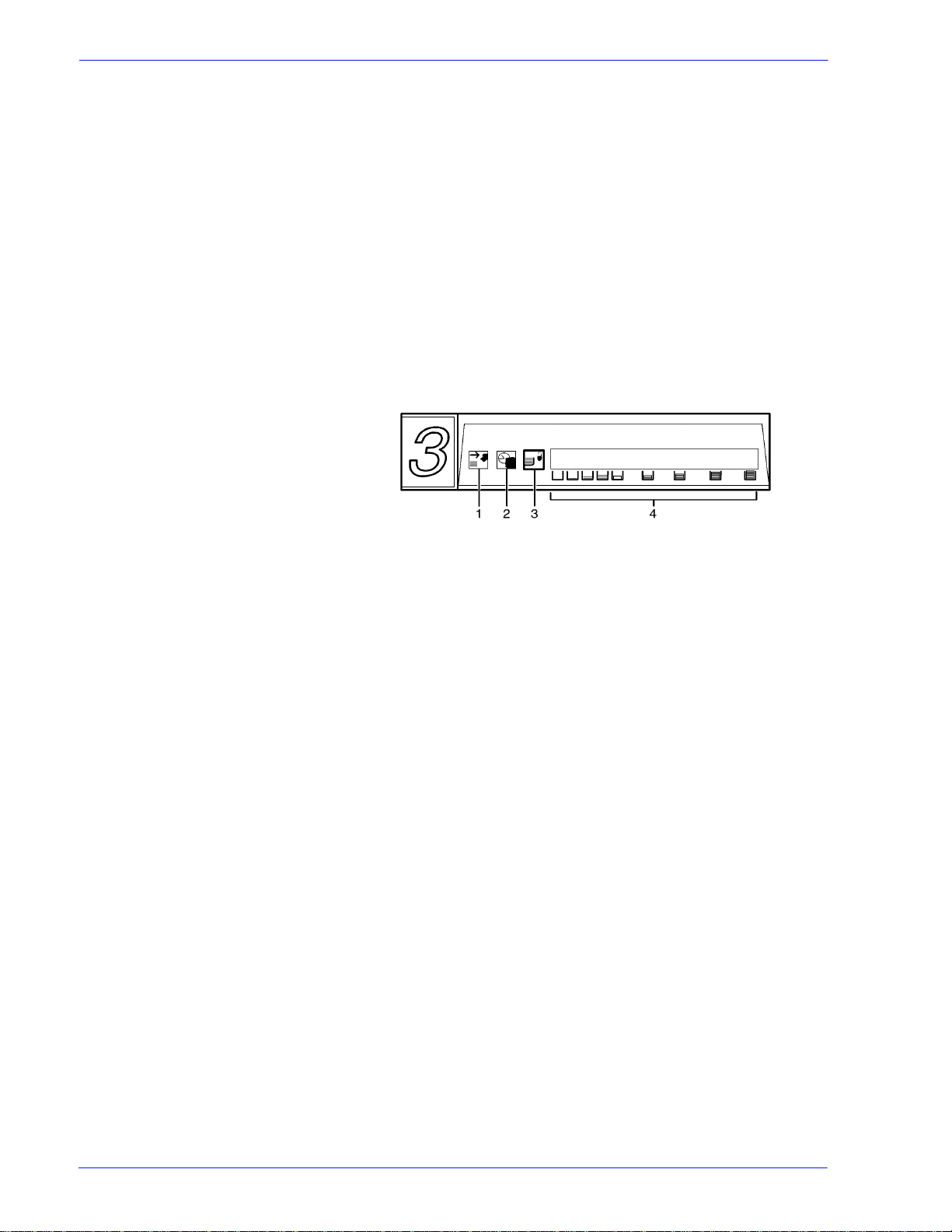
Figure 2-3. Feeder/paper tray control panel
1. Ready to Open indicator
2. Please Wait indicator
3. Tray Unlock button
4. Paper Level indicators
Ready to Open
indicator
Please Wait
indicator
Tray Unlock button Enables the tray to be opened.
Glows green when the tray can be pulled out and paper can be
added to it.
Shows that the tray is in motion. This indicator is lit red when the
Tray Unlock button i s pressed, while the tray is lowering, and while
the tray is rising. The indicator goes off when the tray elevator
reaches its destination.
• If the tray is in use when this button is pressed, the feed
selection switches to the backup tray if one has been
identified. Otherwise, pri n ting stops.
• If the tray is in use and selected as a bac kup tray, pressing the
Tray Unlock button causes the tray elevator to lower and the
tray to be unavailable for auto switching.
• If the tray elevator is in the raised posit ion and the tray is not in
use or selected as a backup tray, pressing this button causes
the elevator to lower with no effect on printing operations.
This button functions when the Please Wait indicator is off.
DocuTech 128/155/180 HighLight Color Operator Guide 2- 9
Page 28

System components
Paper Level
indicators
Display the approximate quantity of p aper in the tray. Each display
shows paper by quarter reams up to one ream, and then by full
reams. The green indicator appears above it s Paper Level
indicator.
Sample tray
NOTE: High volume printer configuration only
The sample tray, located on top of the printer, receives output
such as transparencies, sample sheets from printing jobs, prints
from system files such as forms, and wast e sheets that cannot be
sent to the purge tray.
Monitor the sample tray and empty it when it contains 100 sheets.
The system does not notify you when the tray is full.
Attention light
NOTE: High volume printer configuration only
An Attention light is mounted on top of the inverter module. Thi s
light either blinks or modulates (alter nately brightens and dims)
when the printer requires operator attention. The light has three
states:
Off: No printer problems exist that require attention.
Steady light: A situation exi sts that needs attention soon.
Flashing: The printer has stopped and requires your attention
immediately.
NOTE: When the Attention light starts flashing, an explanatory
message appears on the controller screen.
Purge tray
NOTE: High volume printer configuration only
The purge tray is loc ated on top of the l ast f eeder/ st ack er module.
Aborted sheets (for example, damaged sheets or sheets cleared
after a paper jam) are sent to thi s tray. The purge tray should be
emptied when it has received 100 sheets of p aper.
The system does not notify you when the tray is full.
2-10 DocuTech 128/155/180 HighLight Color Operator Guide
Page 29
System components
Inverter feeder/stacker
NOTE: High volume printer configuration only
Each output feeder/st acker has offset ting cap ability and a cap acity
of 2500 sheets of 20 pound or 80 gsm paper.
This capacity does not apply to 11 by 17 inch and A3 papers.
Because of the additional weight these large sheets add to the
bins, each bin is restricted to hol d only up to 1500 sheets of A3 or
11 by 17 inch papers , fo r s a fe ty re a s o n s.
Figure 2-4. High capacity stackers (HCS)
The stackers can stack the pri nted output in the bin three ways:
1. Directly onto the bin platform.
2. Into a container that is set on top of the bin platform.
NOTE: The stacking capacity is approximately 100 to 150 sheets
less when stacking into a cont ainer.
3. Onto a pallet without a container (for paper sizes 11 by 17
inches or A3 only).
Using the stacking windows on the user interface, you can select
the level to which paper will be stacked in the HCS.
A stacking elevator maintains the paper at the proper level for
stacking and lower s the stack for unloading. An offset mechanism
offsets print ed sets toward the front or back of the HCS bin.
The elevator platform lowers under the following conditions:
• The bin capacity has been reached.
• A selection to lower the platform is entered at the printer
control console or a user interface window.
• The job being printed reaches a designated unload boundary.
Each HCS bin has unlinked double doors to give you easy and
safe access for unloading output from the printer.
The elevator bin platform automatically rises when the doors are
closed after the stacker has been unloaded.
Bin control panels
on stackers
DocuTech 128/155/180 HighLight Color Operator Guide 2- 11
Each stacker bin has a control panel consisting of buttons and
indicators.
Page 30

System components
Figure 2-5. High capacity stacker bin control panel
1. Ready to Unload indicator on stacker bins
2. Please Wait ind icator on stacker bins
3. Bin Unload button on stacker
4. In Use indicator on stacker bin
Ready to Unload
indicator on stacker
bins
Please Wait
indicator on stacker
bins
Bin Unload button
on stacker
In Use indicator on
stacker bin
When this indicator glows, you can remove printed sheets from
the stacker bin.
When this indicator glows, the elevator is in motion. This indicator
turns off when the platform reaches its destination.
Lowers the bin elevator.
• If the bin is in use when this button is pressed, the printed
pages begin stacking i n the oth er stacker bin, if auto swit ching
has been enabled.
• If the bin is not in use, pressing this button does not affect
printing operations.
When this indicator glows, the bin has been made ready to receive
output.
Feeder/stacker modules
The feeder/stacker modules cont ain the high-cap acity feeder trays
and the stacker bins. The printer may have up to four feeder/
stacker modules (including t he inverter f eeder/stac ker), cont aining
feeder trays 3, 4, 5, and 6, and stacker bins A, B, C, and D. Each
module contains one high-capacit y feeder tray and one high
capacity stacker bin.
High-capacity
feeders
2-12 DocuTech 128/155/180 HighLight Color Operator Guide
The high-capacity feeder (HCF) trays are located in the bottom
half of the feeder/stacker modules. Each HCF tray can hold up to
2500 sheets of 20 pound or 80 gsm paper.
The high-capacity feeder trays can handl e paper sized from 8 by
10 inches / 203 by 254 mm to 17 by 14.02 inches / 432 by 356
mm.
Unlike the processor feeder trays, the HCF trays have Paper
Level switches, which detect the posit ion of the elevator to
determine the fullness of the tray.
Page 31

System components
High-capacity
stackers
The high-capacity st acker (HCS) bins are loc ated in the top half of
the feeder/stacker modules, accessed through double doors.
Two high-capacity stacker bi ns are standard, with up to two
additional bins available as options (providing up to four bins
total). Each bin holds up to 2500 sheet s of 20 pound or 80 gsm
paper.
More High volume printer configurations
In addition, the high volume printer is available with three or four
feeder/stacker modules.
Figure 2-6. Printer with inverter feeder/stacker + feeder/
stacker + feeder/ stacker
Figure 2-7. Printer with inverter feeder/stacker + feeder/
stacker + feeder/ stacker + feeder/stacker
The illustrations above show a High volume printer configuration
with two feeder/stacker modules and a bypass transport, and a
printer with three feeder/stacker modules and a bypass transport.
With the bypass transport installed, the printer can support up to
three feeder/stacker modules, including the inverter feeder/
stacker.
DocuTech 128/155/180 HighLight Color Operator Guide 2- 13
Page 32

System components
Production publisher
The standard base components, speci al features, and
configurations of the Xerox DocuTech 180 HLC production
publisher printer are shown in the following figures.
Figure 2-8. Production publisher: Printer + 2-tray interposer +
stitcher/binder
1. Convenience tray
2. Interposer
3. Finisher
4. Top tray
Convenience tray
The convenience tray provides an area to place documents or
other items while you are at the printer.
2-14 DocuTech 128/155/180 HighLight Color Operator Guide
Page 33

Interposer
NOTE: Production publisher configuration only
The two-tray Interposer module is located b etween the print
engine and the Finisher. The Interposer inserts blank or preprinted
sheets as required.
System components
Figure 2-9. Interposer (production publisher only)
The following lists the interposer components
1. Paper transport (lower)
2. Paper transport (upper)
3. Inserter tray
4. Feeder/inserter tray
DocuTech 128/155/180 HighLight Color Operator Guide 2- 15
Page 34

System components
Finisher
NOTE: Production publisher configuration only
Figure 2-10. Finisher
In the finisher, prints can be collated, and stitched or bound, as
required for a job. The following lists the finisher components:
1. Bindexer
2. Stitcher
3. Stacker
4. Binder
5. Binder tape reel
6. Sti tcher wire spools
7. Top tray
The bindexer
NOTE: Production publisher configuration only
The bindexer is a three-bin sorter that collates the pages of each
print set. As the pages of the print set are fed to the bindexer, the
bindexer moves up and down to collate them.
The stitcher
NOTE: Production publisher configuration only
When the job requires stitched output, the st itcher cut s and inserts
the wire stitches into each print set. The stitch length is related to
such factors as the number of pages in the print set and the print
stock weight. A single stitch can be placed in the portrait or
landscape print position. Dual stitching is available for landscape
and portrait prints. Stitch placement can be changed through the
DocuSP software.
NOTE: For more information about setti ng sti tch pla cement, refer
to the on-line help system.
2-16 DocuTech 128/155/180 HighLight Color Operator Guide
Page 35

System components
The stacker
NOTE: Production publisher configuration only
The stacker collects unfinished or finished stitched or bound jobs.
When the stacker is full, or the job is completed, the stacker door
opens and the stacker drawer that holds the prints comes out.
After the stack er drawer is unloaded, the system retracts the
drawer and closes the door. The stacker also can be unloaded
during the printing cycle to check the quality of the print sets by
changing the printer options.
NOTE: For more information, refer to the on-li ne h elp system.
The binder
NOTE: Production publisher configuration only
When a job requires bound output, a length of pre-glued paper
tape is placed on a heated surface called the binder platen. The
system aligns the pages of each print set before placing t he set on
the tape. Binder flappers then press the tape to the sides of the
set. The combination of the heat i n the binder and the pressure of
the flappers glues the tape to the set.
Function of the
bypass transport
NOTE: For information about adjusting the binder tape
registration and the binder tape length, refer to the on-line help
system.
The top tray
NOTE: Production publisher configuration only
Prints are delivered to the top tray beca use the pri n ts are
oversized or because the top tray was selected on the screen.
The bypass transport device is no t available for this configuration
(four feeder/stacker modules).
The printer is available in a Production configuration which
includes a two-tray Interposer and the in -line Binder/Stitcher
Bypass tr ansport
The printing system is avail able in several confi gurations, and may
be configured with a bypass transport.
The bypass transport moves paper from the stacker to a thirdparty finisher such as a stitcher , booklet maker, tape binder, and
so on. By making selections on the user interface windows, you
can program the printer to send output to the bypass transport,
which feeds the output to the finishing equipment.
Paper stocks
supported on
bypass transport
DocuTech 128/155/180 HighLight Color Operator Guide 2- 17
The bypass transport a ccepts all paper stocks on which the prin ter
can print, and it accommodates simplex and duplex printing.
Page 36

System components
DFA suppor t The bypass transport meets the Xerox Document Feeding and
Finishing Architecture (DFA) specifications. The system software
supports DFA. However, in order for the bypass tr ansport to
function correctly, you need to set up finishing personality profiles
to identify your finishing device to the printing system. (The
customer support represent ative for your finishing devi ce can give
you the information you need to create a personality profile for
your third-party finishing devi c e.)
For information on marketing partners that provide solutions for
support and interface with finishers, contact your local Xerox sal es
representative.
Bypass transport on the production publisher
Depending on the finisher configuration, the bypass transport is
located inside the finisher module on the Pro duction publisher
configuration. Bypass tr ansport function is the same as the
external bypass transport module.
NOTE: The Production publisher finisher is available with or
without the bypass transpor t.
Bypass transport on the High volume printer
Connected to the last feeder/stacker module. The bypass
transport option enables third-party finishing devices to interface
directly with the printing system. The bypass transport allows you
to customize your printer for increased efficiency and specialized
applications involving finishing.
NOTE: Systems configured with the external bypass transport
can have a maximum of two (2) feeder/stacker modules. See
figure 2-13.
7 by 10 inch enablement kit
The 7 by 10 inch enablement kit all ows the print ing system to pr int
on 7 by 10 inch/178 by 254 mm paper siz e, with thro ughput speed
of up to 206 PPM.
Paper paths
The paper path is the route that materials (paper, transp arencies,
labels, and so on) follow through the printer f rom the feeder trays
to the output bins or finisher.
2-18 DocuTech 128/155/180 HighLight Color Operator Guide
Page 37

System components
High volume printer paper path
The following figure shows the path the paper takes through the
high volume printer.
Figure 2-11. Route of paper through the high volume printer
1. Processor feeder tray 1
2. Processor feeder tray 2
3. High-capacity feeder tray 3
a. Side 1 of sheet leaving feeder tray
b. Drilled holes (on right edge)
c. Origin 0,0: portrait orientation
DocuTech 128/155/180 HighLight Color Operator Guide 2- 19
Page 38

System components
4. High-capacity feeder tray 4
a. Side 1 of sheet leaving feeder tray
b. Drilled holes (on right edge)
c. Origin 0,0: portrait orientation
5. Paper inverter
6. Duplex inverter
7. Sample tray
8. High-capacity stacker bin A
a. Side 2 of sheet stacked in bin
b. Drilled holes (on left edge)
c. Origin 0,0: portrait orientation
9. High-capacity stacker bin B
a. Side 2 of sheet stacked in bin
b. Drilled holes (on left edge)
c. Origin 0,0: portrait orientation
10. Purge tray
11. Bypass transport
a. Side 2 of sheet passing through bypass transport
b. Drilled holes (on left edge)
c. Origin 0,0: portrait orientation
2-20 DocuTech 128/155/180 HighLight Color Operator Guide
Page 39

System components
Production publisher paper path
The following figure shows the path the paper takes through the
production publisher.
Figure 2-12. Route of p aper t hrough the pr oducti on publis her
1. Processor feeder tray 1
2. Processor feeder tray 2
3. High capacity paper tray
4. Paper inserter tray
5. High capacity paper tray
6. Duplex inverter
7. Purge tray
8. Bypass transport
9. Bindexer area
10. Bind area
11. Stitch area
12. Stac ker area
Bypass transport paper path
The following figures show the paper p ath through the bypass
transport, viewed from the front of the printer.
DocuTech 128/155/180 HighLight Color Operator Guide 2- 21
Page 40

System components
High volume printer bypass transport paper path
Figure 2-13. Bypass transport paper path (high volume
printer configuration shown)
1. Sheet path
2. Exit rollers
3. Floor
2-22 DocuTech 128/155/180 HighLight Color Operator Guide
Page 41

The System
System Hardware
System components
The basic hardware components of the DocuTech 128/155/180
HLC systems are the DocuSP controller and the printer.
The DocuSP controller
The DocuSP controller is the connection between you and the
system. You communicate through the DocuSP software by
selecting and managing the jobs displayed on the screen and
sending them to the printer for production. The system also
communicates messages and instructions to you on the Print
Services interface screen.
The controller consists of a specially-configured workstation and
uses proprietary Xerox hardware, firmware, and software.
Speci fications can be obtained from your Xerox customer
representative or by accessing the Setup, System Configuration
feature on the DocuSP user interface.
NOTE: Controller hardware configurations are subject to change
to keep up with advances in technology.
Controller overview
The controller receives LCDS*, IPDS, PostScri pt, and PCL data
streams from a mainframe host or a workstation cli ent, processes
the data, and sends it to the printer. The controller also provides
the printer with print data and commands and receives status
information from the printer.
The controller consists of a workstation, which is run by the Sun
Solaris Operating environment. Also resident on the controller is
the Document Services Platform application software, known as
DocuSP software, which manages all printing, diagnostic, and
administrative functions on the printing system.
The DocuSP software includes a full-c olor graphical user
interface, which enables you to interact wi th the printi ng system to
set up and configure the system, to set up and implement system
options, to run print jobs, etc.
Online Help (menus and buttons) provides access to online help
that contains information wh en request ed.
NOTE: LCDS is not available on the Production publisher
configuration at this time.
DocuTech 128/155/180 HighLight Color Operator Guide 2- 23
Page 42

System components
Accessing DocuSP remotely (Remote Workflow)
Remote Workflow, a remote graphical user interface (GUI), is
available for installation from a CD. Remote Workflow allows you
to manage your DocuSP-based printers from a single PC or Sun
workstation. You may set your preferences from the remote client
to disable or enable some or all connections.
Remote Workflow allows you to configure the printers that you
want to manage, and provides real time status of the printers. You
may switch between the printers that you are managing, but you
can display only one printer GUI at a time.
The remote client GUI looks and functions the same as the local
DocuSP GUI on the controller.
Moving the controller
To ensure consistent performance and avoid any damage to
equipment, follow these rules for placi ng the components of the
workstation controller .
Do:
Use the controller stand that comes with your printing system
equipment.
Keep the processor in an upright, vertical positi on.
Allow at least 6 i nches / 152 mm of unobstructed space at t he front
and rear of the processor, so the fan and vents are not blocked.
CAUTION: Do not place the monitor on top of the processor. Do
not block any fan or vent on the front, sides, or rear of the
processor.
Do not:
Do not place the monitor and processor on a desk or table top.
Do not place the monitor on top of the processor.
Do not allow any piece of equipment to blow warm air into the air
intake vents of the processor.
Do not place the processor on its side, or in any other positi on but
the upright, vertical position achieved by using the controller
stand.
Do not place the processor or monitor on top of the printe r.
Tape drives overview
The DocuTech 128/155/180 HLC supports several types of tape
drives that may be used to load resources (forms, font s, etc. ) or to
submit offline LCDS print jobs.
A 26-track cartridge tape dri ve can be used only to import
resources to the system disk. A 9-track or 36-track tape drive can
be used to submit print jobs to the printer or to load resources.
2-24 DocuTech 128/155/180 HighLight Color Operator Guide
Page 43

System components
The DocuSP Tape Client software enables transmission of data
from a cartridge or open reel tape to the DocuSP controll er via the
Socket gateway.
The 4 GB external SCSI quarter inch cartridge (QIC) tape drive is
an external device. The cartridge tape drive connects to the
controller through the SCSI port on the processor back panel.
Like the diskette and DVD drives, this tape drive is not an input
source for print jobs or for any other data or application. You can
use it to load resource files, and the servi ce representative uses it
to load system maintenance files or to save diagnostic
information.
36-track cartridge
tape drive
Figure 2-14. 26-track cartridge tape drive
An 18/36-track cartridge tape drive is an option. You can use this
drive to load resources and to submit offline LCDS print jobs.
Peripheral cabinet (9-track and 18/36-t rac k tape drives)
Some Xerox customers may already have a peripheral cabinet
that houses a 9-track magnetic and an 18/36-track cartr idge tape
drive. If a peripheral cabinet has either of the following 18-track
tape drives, they are not supported:
STK 4220 MOD 1 tape drive
STK 4220 MOD 2 tape drive
DocuTech 128/155/180 HighLight Color Operator Guide 2- 25
Page 44

System components
Figure 2-15. Peripheral cabinet
1. 9-track magnetic tape drive
2. 18/36-track cartridge tape dri ve
Paper sizing and print speed
The printer paper trays have edge gui de sensors that det ect paper
length and width. The system select s correct paper trays for the
print job based on the paper parameters, such as size, weight,
color, or coating, specified in the job as follows:
• If an exact match is found, the print job continues.
• If an exact match is not found, the operator can specify in t he
job for the printer to do one of the following:
– Stop pri nting the job and print an error sheet.
– Print the data on an oversized sheet.
If you encounter any problems related to pa per sizing, contact
your lead operator or Xerox service rep resentative.
2-26 DocuTech 128/155/180 HighLight Color Operator Guide
Page 45

System components
Long and short edge
feeding
To feed through the printer, the l eading edge of t he p aper must be
at least 10 inches long. Therefore, the following standard sizes of
paper must be loaded so that sheets feed long edge first:
• 7 by 10 inch
•B5
•A4
• US letter
•B4
• US legal
The following papers, which have long edges greater than 14.33
inches / 364 mm must feed short edge first:
•A3
• US ledger or US tabloid
NOTE: JIS B4 can be fed either long edge or short edge first.
DocuTech 128/155/180 HighLight Color Operator Guide 2- 27
Page 46

System components
2-28 DocuTech 128/155/180 HighLight Color Operator Guide
Page 47

3 Routine maintenance
This section describes the routine activities you perform to
maintain the reliability and productivity of your printer.
Cleaning and maintenance overview
Some printer components need to be cleaned periodical ly to help
keep the system operating reliably, and to ensure that the print
quality is consistent.
When supplies get low, an indicator will appear in the DocuSP
Print Services window on the DocuSP controller. You should
respond to the fault or message as soon as possible to avoid a
printer shut down.
The system provides dry ink to the printer from a bottle located in
the printer. When the screen displays an “empty” message, a full
dry ink bottle must be install ed.
Waste dry ink empti es into a container located at the side of the
printer, under the toner filter. When this container becomes full, it
must be replaced.
Fuser lubricant must be added to the fuser reservoir in the printer
when a “low” message on the screen directs you to do so. Fill the
fuser reservoir at this time or the printer shuts down.
For information on cleaning the processor sensors, the reflecting
surfaces, and the finisher sensors, refer to the Problem solving
chapter.
NOTE: The DocuTech HLC fuser oil is a specially blended fuser
shield specifically for the DocuTech HLC systems.
CAUTION: The DocuTech HLC fuser shield must not be used in
any other Xerox product.
CAUTION: Use only the DocuTech HLC fuser shield in the
DocuTech HLC systems.
Necessary Precautions
For your own safety and to protect the system, it is impo rtant to
take the following precautions wheneve r you perform cleaning
and replacement tasks.
• Use only the cleaning and replacement supplies that are
DocuTech 128/155/180 HighLight Color Operator Guide 3-1
Page 48

Routine maintenance
approved or recommended by Xerox. If you use other
supplies, you may damage the system.
• Keep supplies in stock as listed in the Service and supplies
chapter.
• Whenever you use or remove a part from the system, handle
the part carefully. Note any informative labels on the system.
• Keep atomized and aerosol sprays away from the system.
• Pour cleaning liquids onto a cl oth. Do not po ur or spr ay l iqui ds
directly onto system par ts.
• Before reinstalling a system part that has been cleaned with a
liquid, ensure that the part is dry.
• Always use a drop cloth when replacing the dry ink bottle,
highlight color contai ner, or when adding fuser shield.
• Some parts of the system, such as the fuser, get hot during
operation. To ensure that you do not burn yourself, be careful
when working around these part s.
WARNING: The fuser can reach a temperature of approximately
425°F (218°C). Exercise care to prevent burns when working near
this area.
Finisher precaution
NOTE: Production publisher configuration only
The system uses stitcher wire from two spools located below the
stacker. Stitcher spool A is used for portrait, top corner stitches.
When stitcher spool A is empty, it must be replaced with a new
stitcher spool. S tit cher spool B is used for port rait dual stitch es and
landscape stitches.
To replace stitcher spool B, contact the Customer Support Center;
refer to the section, “Calling for ass istance”, in this guide.
To replace stitcher spool A, refer to the section, “Replacing the
stitcher spool A”, in this guide.
The system applies binder tape from a reel mounted in the binder
drawer in the finisher. You will need to replace the binder tape
periodically.
WARNING: All areas of the binder drawer, including the binder
tape, are approximately 425°F (218°C) and may cause a serious
burn to the operator. If the binder has been in a "Ready" condition,
allow the binder to cool for at least one hour before attempting to
clean the binder.
3-2 DocuTech 128/1 55/180 High Light Col or Operat or Guide
Page 49

Paper
Routine maintenance
You can add the same kind of paper to a tray when the supply is
low without stopping the printer. You mu st have the s ame paper or
stock loaded in two trays for the system to continue p ri nting while
you are loading the other tray.
Storing paper
It is important to store paper correctly. Temperature and humidity
affect the way your printer processes paper.
Store paper in the cartons it came in. To reduce the possibility of
moisture absorption, always place cartons on a wooden pallet or
store them in a cabinet off the floor.
After removing the paper from its carton, always store it:
• In its wrapper
• On a flat surface
• In a closed cabinet
• In a cool, dry area
o
• In 68 to 76
• In 35% to 55% humidity
F. / 20 to 24.4o C.
Figure 3-1 Storing paper correctly
DocuTech 128/155/180 HighLight Color Operator Guide 3- 3
Page 50

Routine maintenance
Conditioning paper
Figure 3-2 Recommended temperature and humidity for
paper storage
Because temperature and humidity affect paper performance in
the printer, you need to condition paper before using it. To
condition paper, store it for a specified length of time in the same
type of environment as your printer.
The length of time you should condition your paper depends on
the amount of paper and the dif fer ence between the storage and
operating temperatures.
Use the following chart to determine the number of hours needed
to condition stacked cartons of paper.
NOTE: The numbers in the top two rows indic ate the te mperature
difference between the storage area and the operating
environment, not actual room temperatures .
3-4 DocuTech 128/1 55/180 High Light Col or Operat or Guide
Page 51

Table 3-1. Paper conditioning
T e mperature difference between storage and
operating areas
Routine maintenance
Paper curl
Fahrenheit
Centigrade
10
5.5
o
o
o
15
20o25
8.5o11
o
o
13
o
30
17
o
o
40
22
o
o
50
26
o
o
Cartons Hours needed to condition the paper
1481114172434
5591215182535
10 8 14 18 22 27 38 51
20 11 16 23 28 35 48 67
40 14 19 26 32 38 54 75
Example: If you want to move ten car tons of p aper from a s torage
area with a temperature of 90
temperature of 70
o
F. (a 20
o
F. to an operating area with a
o
difference), you should do so at least
18 hours before using the paper.
Before the manufacturer cuts paper into sheets, it is stored on
large rolls. After it is cut and packaged, it ret ains some of the curl
from the rollers.
Although it is unnecessary to load paper with the curl facing up or
down, best result s occur when you are consistent. For example, if
you open paper with the wrapper seam up, always load i t in the
tray that way.
DocuTech 128/155/180 HighLight Color Operator Guide 3- 5
Page 52

Routine maintenance
Adding paper to tray 1 or 2
The following steps must be performed to add paper to tray 1 or 2.
1. Press the Tray unlock button on the front of the tray. Wait for
the red "Please wait" light to go off.
2. When the green "Ready to open" light comes on, pull the tray
out until it stops.
Steps 3 through 5 of loading paper into tray 1 o r 2 are
illustrated in Figure 3-3.
3. Press the green release tab.
4. Lift the metal handle on the feed belt and remove any paper
under the belt.
5. Move the rear guide to the back of the tray.
Figure 3-3 Preparing the paper tray
NOTE: To load the paper correctly, refer to the label located
on the inside panel at the front of the paper tray. Remove any
damaged sheets from the top of the stack.
CAUTION: Do not load the paper above the red li ne. A jam could
occur if too much paper is loaded in the tray.
6. Load the required paper into the paper tray. Load paper with
the curl side facing down. Load Xerox pap er with the package
wrapper seam side facing up.
NOTE: When loading drilled paper, be sure to fan the edge
where the holes are located.
7. Position the stack against the front right corner of the tray, as
shown in Figure 3-4. This is indicated by the green arrow on
the bottom of the tray.
3-6 DocuTech 128/1 55/180 High Light Col or Operat or Guide
Page 53

Routine maintenance
For stock outside the recommended limits, refer to the
"Technical information" chapter in this guide.
Figure 3-4 Positioning the stack
8. Move the rear guide forward until it touches the edge of the
stack.
9. Lower the feed belt.
10. Close the tray slowly, but firmly, until it latches.
Using the custom transfer assist blade
The custom transfer assist blade in the printer assures good print
quality for your jobs. A kit is available allowing you to customize
the transfer assist blade for use with nonstandard paper sizes.
You cannot use the custom transfer assist blade for print jobs that
use more than one paper size. In addition, the following paper
lengths cannot use the blade:
DocuTech 128/155/180 HighLight Color Operator Guide 3- 7
Page 54

Routine maintenance
In U.S. markets
– 11.1 to 11.4 inches/282 to 290 mm
– 11.8 to 12.1 inches/300 to 307 mm
– 13 to 13.5 inches/330 to 343 mm
In non-U.S. markets
– 11.1 inches to 11.4 inches/282 to 290 mm
– 11.8 inches to 12.1 inches/300 to 307 mm
NOTE: With these paper sizes, tr ansfer efficiency may be
reduced.
CAUTION: To avoid damage to the photoreceptor, you must set
the tray size with the transfer assist blade.
Installing the
custom transfer
assist blade
Setting tray size with
the custom transfer
assist blade
The custom transfer assist blade comes in a package containing
detailed instructions. Be sure you follow the instructions carefully.
CAUTION: To prevent damage to the system, have your service
representative show you the procedur e before you attempt to
customize and install a transfer assist blade for the first time.
When you are using the custom transfer assist blade, you must
set the tray length. Use the following two tables to determine the
tray length setting to use.
Table 3-2. Tray length settings for custom transfer assist
blades (U.S. markets)
Paper Size Set Paper Size
11.5 to 11.7 inches/292 to 297 mm 11.7 inches/297 mm
12.1 to 12.9 inches/307 to 328 mm 13 inches/330 mm
13 to 13.9 inches/330 to 353 mm 14 inches/356 mm
Table 3-3. Try length settings fro custom transfer assist
blades (Non-U.S. markets)
Paper Size Set Paper Size
10 to 10.9 inches/254 to 277 mm 11 inches/279 mm
11.5 to 11.6 inches/292 to 294 mm 11.7 inches/3297 mm
12.1 to 12.9 inches/307 to 328 mm 13 inches/330 mm
3-8 DocuTech 128/1 55/180 High Light Col or Operat or Guide
Page 55

Adjusting for paper curl
Each sheet of paper has a natural curve call ed the curl. Storing or
using the paper under humid conditions may increase the curl.
When too much curl causes paper handling problems, adjust the
decurler in the processor. The decurler flattens the paper after
fusing.
Measuring the paper curl
1. Program and print five 1-sided, 8.5 x 11 inch (216 x 279 mm)
sheets to the top tray.
NOTE: Keep the image toward you, as shown in Figure 3-5.
2. Measure the amount of curl in the prints by holding the five
prints in the top center of the short edge.
Routine maintenance
Figure 3-5 Measuring the paper curl
3. Place the bottom edge of the prints over the p aper curl
measurement chart in this guide.
• If the print curl on the printed paper measures between +1
and - 2, do not change the decurler setting.
• If the curl is between +2 and +3, or - 3 and - 4, refer to the
procedure, "Adjusting the decurl er lever," in this section.
NOTE: Superior performance for greater than substance 32
(120 g/m2) can be achieved between +1 and -1 curl.
DocuTech 128/155/180 HighLight Color Operator Guide 3- 9
Page 56

Routine maintenance
Note: Corners of
the sheets of pape r
should not exceed
curl shown in this
chart.
Image
Move green
decurler lever
Move green
decurler lever
Figure 3-6 Measuring the paper curl
3-10 DocuTech 128/155/180 HighLight Color Operator Guide
Page 57

Adjusting the decurler lever
Perform the following steps to adjust the decurler lever.
CAUTION: Do not use any paper that is not suitable for system
use.
1. Open the right door of the processor.
2. Locate the decurler lever in area 7 of the paper p ath, as shown
in the figure below.
Routine maintenance
Figure 3-7 Locating the decurler lever
3. If the print cur l is +2 or more, move the green decurler lever to
the right.
4. If the print curl is -3 or more, move the green decurler lever to
the left.
5. If the decurler adjustment does not eliminate the paper curl
problem, or for other curl problems, turn the stack of paper
over in the paper tray.
6. If there is still a curl problem, perform steps 1 to 4 again.
NOTE: A final solution to the curl problem may be to load a
new ream of paper.
7. Close the processor door.
DocuTech 128/155/180 HighLight Color Operator Guide 3- 11
Page 58

Routine maintenance
Maintaining the printer
A screen message is displayed when it is necessary to replace
system supplies. To ensure that the system runs efficiently,
replace the supplies as soon as possible.
Replacing the black dry ink bottle
When directed by a screen message, replace the black dry ink
bottle. If the bottle is not replaced, the pri nter will eventually stop,
and it will not operate until a new bottle is instal led.
CAUTION: To prevent dry ink spills, remove the bottle only when
directed to do so by a message on the screen.
CAUTION: Do not use warm or hot water, or general cleaning
solvents to remove dry ink from your skin or clot hing. The heat or
solvent will set the dry ink and make it difficult to remove.
CAUTION: If any dry ink should get on your clothes, brushing
with a dry paper t owel or a stif f -bris tled b rush may remove the i nk.
If not, launder your clothes with detergent and cold water. Tell a
commercial dry cleaner that the spot is dry ink or "t oner" so that
they will not use a solvent that will set the dry ink stain.
Replace the black dry ink bottle
The following steps must be performed to replace the bl ack dry ink
bottle.
1. Open the front processor acces s door and loc ate the b lack dry
ink bottle at the left side of the processor.
2. Place a drop cloth on the floor under the dry ink bottle area.
3. Remove the empty bottle by grasping the bottle handle. With a
slow , firm motion, pull the bottle from the bottle guide.
a. Pull the empty dry ink bottle out until it stops.
b. Move the green handle to the unlatched position.
c. Remove the empty bottle and discard it.
3-12 DocuTech 128/155/180 HighLight Color Operator Guide
Page 59

Routine maintenance
Figure 3-8 Removing the empty bottle
4. To insert a new bottle, place the bottle on the edge of the bottle
guide.
a. With a slow, firm motion push the bottle into the dispense
position over the hopper.
b. Turn a new bottle of dry ink upside down and shake the
bottle thoroughly to loosen the contents. Insert the full
bottle until it stops.
Figure 3-9 Inserting and latching the bottle
c. Slide the full bottle all the way into the system.
d. Hold the bottle in place with one hand and remove the
DocuTech 128/155/180 HighLight Color Operator Guide 3- 13
Page 60

Routine maintenance
paper seal by pulling it toward you with the other hand.
Discard the seal along with the drop cloth.
Figure 3-10 Removing the paper seal
5. Close the processor access door.
NOTE: If any dry ink should get on your skin, wash with mild
soap and cold water.
Replacing the highlight color container
The highlight color container hol ds the color dry ink. When
directed by a screen message, replace the highlight color
container. If the highlight col o r container is not replaced, the
printer stops, and it will not operate until the highlight color
container is replaced.
CAUTION: Do not use warm or hot water, or general cleaning
solvents to remove dry ink from your skin or clot hing. The heat or
solvent will set the dry ink and make it diff icult to remove. If any
dry ink should get on your skin, wash with mild soap and cold
water.
If any dry ink should get on your clothes, brus hing with a dry pa per
towel or a stiff-bristled brush may remove the ink. If not, launder
your clothes with detergent and cold water. Tell a commercial dry
cleaner that the spot is dr y ink or "toner " so that they will not use a
solvent that will set the dry ink stain.
1. Open the front processor access door and locate the highlight
color container at the right side of the processor.
2. Place a drop cloth on the floor under the highlight col or
container area.
3-14 DocuTech 128/155/180 HighLight Color Operator Guide
Page 61

Routine maintenance
3. Remove the empty container by grasping its handle. With a
slow, firm motion, remove the container.
Figure 3-11 Highlight color container
4. Pull the container out until it stops.
5. Remove the container and discard it.
6. To insert a new bottle, place the bottle on the edge of the bottle
guide. With a slow, firm motion, push the bottle into the
dispense position over the hopper.
7. After the bottle is in the dis pense position, remove the seal.
You may encounter some resistance.
8. Close the processor door.
DocuTech 128/155/180 HighLight Color Operator Guide 3- 15
Page 62

Routine maintenance
Changing the highlight color Customer Changeable Units
The highlight color Customer Changeable Unit (CCU) consists of
the color dry ink bottle and supporting equipment. In order to
change the highlight color or to service the wire module, you need
to remove the highlight color CCU from the printer.
If you have more than one highlight color CCU, a CCU cart is
provided to allow you to change and store the CCU. If you have
only one highlight color CCU, a service cart is provided to allow
you to remove the CCU for service.
CAUTION: CCU carts should be used exclusive ly f or changing
and storing CCUs. You should always have at least one empty
cart at your site if your printer has more than one color CCU. Do
not attempt to remove or install a CCU without a cart.
CAUTION: Do not remove the CCU after a hard stop , such as
caused by a paper jam, system cras h or rest art, or openi ng a door
during printing, without firs t allowing the system to cycle up and
continue processing for a proper recover y.
Removing the CCU using the CCU cart
To remove the highlight color CCU from the printer:
1. If the printer is not cycled down, Pause the system before you
open the doors and attempt to remove the CCU.
2. Open the printer doors and locate the color housing area in the
center of the printer.
3. Open the top cover of an empty cart.
4. Push the cart up to the printer, lining up the yellow knob on the
cart with the yellow recess on the printer inner cover.
5. Push the cart firmly against the printer until you can feel the
two latch together.
6. Make sure the cart is level.
a. If the cart is not level, loosen the l ocknut holdi ng the height
adjustment knob in place.
b. Use the height adjustment knob to regulate the level.
3-16 DocuTech 128/155/180 HighLight Color Operator Guide
Page 63

Routine maintenance
c. When the HLC unit is level, tighten the lock nut.
Figure 3-12 Leveling the cart
7. Push down firmly on the cart pedal until you hear or feel the
pedal catch. The pedal should stay locked down. The pallet
within the cart is raised.
8. Unlatch the CCU by turning the photoreceptor backup roll er
handle clockwise for a quarter turn to an upright position.
DocuTech 128/155/180 HighLight Color Operator Guide 3- 17
Page 64

Routine maintenance
5. Then, turn the yellow CCU handle a quarter turn clockwise.
Figure 3-13 Unlatching the CCU
9. Using the metal flange of the color CCU, pull the CCU out of
the printer until it is completely in the cart. The flange is
located directly below the bottle.
Figure 3-14 Removing the CCU from the printer
10. Push down firmly on the cart pedal until you hear or feel a
click. The pallet, which now contains the CCU, is lowered into
3-18 DocuTech 128/155/180 HighLight Color Operator Guide
Page 65

Routine maintenance
the cart. If the pallet does not move, check that the CCU is all
the way out of the printer and push down on the pedal again.
Figure 3-15 Closing the top cover
11. Close the top cover and store it.
Inserting a CCU
To insert a CCU, follow these steps.
1. Open the top cover of the cart containing th e new color CCU.
2. Push the cart up to the printer, lining up the yellow knob on the
cart with the yellow recess on the printer inner cover. Make
sure the cart is level.
Figure 3-16 CCU on cart
3. Push the cart firmly against the printer until you can feel the
two latch together.
DocuTech 128/155/180 HighLight Color Operator Guide 3- 19
Page 66

Routine maintenance
4. Push down firmly on the cart pedal until you hear or feel the
pedal catch. The pedal should stay locked down. The pallet
containing the CCU is raised.
5. Using the CCU metal flange, firmly push the CCU into the
printer.
6. Turn the yellow CCU handle counter clockwise for a quarter
turn. If it does not turn, check that the CCU is fir mly seated in
the printer.
Figure 3-17 Turning the backup roller handle
counterclockwise
7. Turn the photoreceptor backup roller handle counterclockwise
for a quarter turn.
8. Make sure that the CCU is completely inserted into the
machine to prevent photoreceptor damage.
9. Push down firmly on the cart pedal until you hear or feel a
click. If the pallet does not drop, check that the CCU is all the
way in the printer and the pallet is released, then push down
on the pedal again.
10. Remove the cart from the printer and close the cart top cover.
11. Close the printer doors.
12. Store the cart.
3-20 DocuTech 128/155/180 HighLight Color Operator Guide
Page 67

Storing the cart and CCU
NOTE: If any dry ink gets on your hands, wash them with soap
and cold water. Heat sets the ink permanently. If any dry ink gets
on your clothes, brush them with a dry paper towel or a stiff
bristled brush. If thi s does not remove the ink immediately, launder
with detergent and cold water. Tell the dry cleaners that the spot is
dry ink for a printer, so they will not use a solvent that sets the
stain.
When you are not using a cart and CCU, store them in a dry, dustfree area that has little variation in temperature and humidity. The
storage area should have a similar temperature and humidity to
the printer room. Maintain the temperature in the range of 60 to
80° F/15 to 26 C° and a relative humidity of 30 to 65 percent.
Removing the CCU using the service stand
Use the service stand to withdr aw the highlight color CCU from the
printer. Use this stand if you do not have a cart.
To set up the service stand:
Routine maintenance
1. If the printer is not cycled down, Pause the system before you
open the doors and attempt to remove the CCU.
2. Open the printer doors and locate the color housing area in the
center of the printer.
3. Place the service stand next to the developer housi ng.
4. By turning the jack screws, adjust the height of the front feet so
that the alignment pins in the service stand are positioned just
below the hole and the docking bracket. Tighten the lock nuts
on the jack screws to lock the jack screws in position.
Figure 3-18 Service stand
DocuTech 128/155/180 HighLight Color Operator Guide 3- 21
Page 68

Routine maintenance
5. Slide the stand toward the machine to engage the pins with
the holes and the slot. The end of the service stand may need
to be lifted slightly to ensure pin engagement.
6. With the service stand i n posit ion against the mac hine and the
pins engaged in the docking bracket, engage the locking
mechanism by applying a force forward on the lever and
compressing the latch spring while turning it to the position
shown.
7. Locate the pin squarely to the machine by ensuring that the
two (2) locating pins in t he service st and are in cont act with t he
docking bracket.
8. With the service stand properly locat ed to the machine and
while observing the level, turn the r ear jack screws to adjust
the height of the service stand so that it is level.
9. Tighten the lock nuts on the jack screws to lock the jack
screws in position.
10. Unlatch the CCU by turning the photoreceptor backup roller
handle clockwise for a quarter turn to an upright position.
Figure 3-19 Unlatching the CCU
3-22 DocuTech 128/155/180 HighLight Color Operator Guide
Page 69

Routine maintenance
6. Then, turn the yellow CCU handle a quarter turn clockwise.
Figure 3-20 Removing the CCU from the printer
11. Using the metal flange of the color CCU, pull the CCU out of
12. To replace the CCU, reverse the above steps.
Adding fuser shield
When directed by a message, add fuser lubricant as soon as
possible. If it is not added, the printer stops after approximately
5,000 prints and not run until fuser shield is added. Please read
the important note below.
NOTE: In 2006, the formula for the DocuTech HLC fuser lubricant
was changed to provide better image quality and to prevent image
transfer. The new fuser formula is called Fuser Shield. The fuser
blend and the fuser shield CANNOT be intermixed in a DocuTech
HLC. To change from one fuser lubricant to another require s a
service call and cleaning or replacing components. The two fuser
formulas are identified with different color bottles and caps. Be
sure the color of the cap of the bottle you are filing from matches
the color of the cap already in the system. Fuser shield
description: blue bottle, white cap with black printing. Fuser blend
description: yellow bottle, black cap with white printing.
the printer until it is completely in the stand. The flange is
located directly below the bottle.
WARNING: The fuser area can reach temperatures of
approximately 425°F (218°C). Exercise ca re to prevent burns
when working in this area.
DocuTech 128/155/180 HighLight Color Operator Guide 3- 23
Page 70

Routine maintenance
CAUTION: Fuser lubricant for other printers is not compatible.
Do not use DocuTech and Do cuPrint fuser agent in a DocuTech
HLC system. Do not use DocuTech HLC fuser shield in a
DocuTech 61xx or DocuPrint 1xx system. The fuser lubricants are
not compatible and will contaminate the system.
1. Open the processor doors.
2. Place a drop cloth on the floor under the fuser area.
3. Open the fuser drawer.
a. Locate the fuser drawer.
b. Grasp the green handle on the fuser drawer and pull it out
until it stops.
Figure 3-21 Opening the fuser drawer
WARNING: Fuser lubricant contains silicone, which can cause
irritation upon cont act wit h the eye. Make sure t hat yo u wash your
hands with soap and water after you finish this procedure.
CAUTION: Fuser lubricant can cause damage to the CCU if any
of the it is spilled into the unit. Use extra care to ensure that no
fuser lubricant is dripped into the CCU.
4. Wipe the fuser lubricant filler area to remove any residual
lubricant.
5. Fill the fuser lubricant reservoir.
a. Pull the fuser lubricant reservoir out until it stops.
b. Remove the reservoir cap by turning it counterclockwise.
3-24 DocuTech 128/155/180 HighLight Color Operator Guide
Page 71

Routine maintenance
Figure 3-22 Preparing to add fuser blend
WARNING: Fuser lubricant spills cause the floor to be slippery. If
any fuser lubricant is spille d onto the floor , it must be removed
immediately.
c. Open a n ew box of fuser lubricant and remove a bottle.
Remove the cap from the bottle of fuser lubricant.
d. Carefully pour the fuser lubri cant into the reser voir until the
level reaches the MAX line. Avoid spilling the fuser
lubricant or overfilling the reservoir.
CAUTION: Do not push the fuser lubricant bottle into the
reservoir with excessive force. There is an anti-splash seal in the
reservoir that could be damaged.
DocuTech 128/155/180 HighLight Color Operator Guide 3- 25
Page 72

Routine maintenance
Figure 3-23 Adding the fuser blend
e. Replace the reservoir cap by turning it clockwise
approximately one full turn. Do not overtighten the cap.
f. Inspect the area around the fus er to ensur e no fuser bl end
was spilled. Clean as required.
g. Push the fuser blend reservoir in until it stops.
6. Push the fuser drawer in until it latches into place.
Figure 3-24 Closing the fuser drawer
3-26 DocuTech 128/155/180 HighLight Color Operator Guide
Page 73

Waste containers
Replacing the 128/155/180 HLC developer waste container
Routine maintenance
7. Close the processor doors.
The fuser blend message disappears after the system makes
approximately 20 prints.
The waste containers in the DT 128/155/180 HLC collect dry ink
and developer after it has been used by the printer. When a
container becomes full, it must be replaced or the printer
eventually stops printi ng. T his secti on cont ai ns the procedure s for
replacing the toner and developer waste containers.
To replace the developer waste container:
1. Open the processor doors and locate the dry ink cartri dge at
the lower center of the printer. The developer waste container
is located below and to the right of the color dry ink bottle.
Figure 3-25 HLC developer waste container
2. Using your right hand, grasp the container by the handle on
top. With your thumb, depress the latch locat ed above the
frame of the machine. Lift the edge of the container from the
tray and remove. Unscrew the cap from the front of the waste
container and use it to close the open end of the waste
container.
3. Discard the waste material and container appropriately.
DocuTech 128/155/180 HighLight Color Operator Guide 3- 27
Page 74

Routine maintenance
4. Insert the new waste HLC developer waste contain er into the
transport assembly. Push the retainer out of the way with your
thumb. Continue seating the new waste cont ainer onto the tray
and release the container latch .
5. Close the processor doors.
Replacing the 128/155/180 toner waste bottle
To replace the toner waste bottle:
1. Open the HLC module door.
Figure 3-26 Opening the HLC module door
2. Remove the toner waste bottle.
3. Remove the flat cap from the top front of the bottle.
3-28 DocuTech 128/155/180 HighLight Color Operator Guide
Page 75

Routine maintenance
Figure 3-27 Flat cap on waste bottle
4. Place the flat cap on the round bottle opening and snap it
down. This prevents spillage when discarding the bottle.
5. Discard the waste material and container by placing the
container in the trash.
6. Obtain a new bottle and open it, placing the cap at the front of
the bottle and snapping it down.
7. Insert the new bottle into the waste module.
Figure 3-28 Inserting a new waste bottle
8. Close the HLC module door .
DocuTech 128/155/180 HighLight Color Operator Guide 3- 29
Page 76

Routine maintenance
Wire Module Removal and Replacement
Replace the wire module only when directed to by the Customer
Support Center.
CAUTION: In the following i nstructions, do not pull on the locat ing
arm of the developer housing. A bent or damaged locating arm
can cause component damage or image quality artifacts.
Do no touch the Electrostati c Voltage (ESV) mount ed to the to p of
the developer housing when removing the wire module. The ESV
is fragile, and susceptible to damage from electrostatic discharg e .
To remove the wire module:
1. Open the processor doors.
2. Using the CCU cart or service stand, slide the HLC developer
module out of the printer Ref er to the procedures on using the
CCU cart or service stand.
Figure 3-29 Wire module retainer springs
3. Release the wire module retainer springs. There is one at
each end at the front and back of the developer housing.
CAUTION: Handle the wire module with care since the wires can
be damaged or broken easily. Do not touch the donor rolls.
Touching the roll surface with your fingers can contaminate the
surface, causing image quality problems.
To replace the wire module:
3-30 DocuTech 128/155/180 HighLight Color Operator Guide
Page 77

Routine maintenance
1. Position the wire module on the HLC developer module.
2. Snap the wire module retainer springs behind the tabs.
3. Slide the HLC developer module into the machine.
4. Latch the CCU into place.
5. Remove the cart or service stand.
6. Close the doors.
DocuTech 128/155/180 HighLight Color Operator Guide 3- 31
Page 78

Routine maintenance
Cleaning the system and its components
NOTE: Follow the procedures in this section only when directed
by Xerox Customer Support center personnel.
Cleaning tasks consist of the following:
• Cleaning the 18/36-track cartridge tape drive
• Cleaning the 26-track cartridge tape drive
• Cleaning the DVD drive
• Cleaning the diskette drive
• Cleaning the sensors and the reflecting surfaces
• Cleaning the display
• Cleaning the exterior surfaces of the system
Cleaning the 18/36-track cartridge tape drive
A cleaning cartridge is shipped with each 18/36-t rack cartridge
tape drive. This cartridge should be replaced after 500 uses.
When the tape drive needs to be cleaned, CLEAN appears in the
message display after a cart ridge is unl oaded and during a rewi nd
or locate operation.
NOTE: CLEAN is a status message, not an error message.
CAUTION: Never power off the tape drive without following the
cleaning procedure once the CLEAN message appears.
CAUTION: The cleaning cartridge must be undamaged and
clean.
To clean the 18/36-track cartridge tape drive read/write heads:
1. Remove any cartridge loaded in the tape drive.
2. Insert the cleaning cartridge.
The cleaning cycle takes approximately 15 seconds.
3. Remove the cleaning cartridge when it is unloaded.
4. Mark the usage on the tape label. Do not use a grease pencil.
You must clean the 18/36-track cartridge tape drive regularly to
keep it functioning properly.
3-32 DocuTech 128/155/180 HighLight Color Operator Guide
Page 79

Cleaning the 26-track cartridge tape drive
The 26-track, or quarter inch cartridge ( QIC ) tape drive heads
should be cleaned at least once a week. If you use the drive for
eight hours or more per day, then you should clean the drive dail y.
The process is simple and requires little time.
1. If there is a cartridge in the tape, r e mov e it.
2. Insert the cleaning cartridge in the tape drive and close the
door. Cleaning begins automatically once the tape is inserted.
3. Allow the tape to run for approximately 30 seconds, then
remove it.
NOTE: Replace the foam pad on the clea ning cart ridge af te r it
has been used three times. The cleaning cartridge itself can
be used 100 times.
Cleaning the DVD drive
Routine maintenance
Follow the DVD cleaning directions and recommended cleaning
frequency.
1. If there is a DVD disk in the drive, remove it.
2. Follow the directions to clean the DVD drive.
Cleaning the diskette drive
The floppy disk drive must be cleaned at recommended intervals
to prevent read and write disk errors.
To clean the diskette drive:
1. If there is a diskette in the floppy disk drive, remove it.
2. Insert the cleaning diskette into the disk drive.
3. Follow the directions on the cleaning diskette to clean the
diskette drive.
4. Remove the cleaning diskette.
DocuTech 128/155/180 HighLight Color Operator Guide 3- 33
Page 80

Routine maintenance
Cleaning the sensors and the reflecting surfaces
CAUTION: Never use abrasive materials or stro ng solv ents when
cleaning sensors.
The following is a list of sensors to clean:
• Q850 and Q861 sensor
• Q1011/1009 sensor and mirror
• High Capacity Feeder/Stacker configuration
• Q1106 sensor
• Q1166 sensor
• Q1107 sensor
• Q1164 sensor
• Production publisher configuration (finisher sensors)
• Q1201 sensor
• Q1202 and Q1203 sensors
• Q1205, Q1206, and Q1207 sensors
• Q1213 sensor
• Q1221, Q1218, and Q1227 sensors
• Q1222 and Q1210 sensors
Cleaning the Q850 and Q861 sensor
1. Open the right and left doors of the printer and locate Area 4.
2. Raise the Area 4 green handle until it locks int o place.
3-34 DocuTech 128/155/180 HighLight Color Operator Guide
Page 81

Routine maintenance
Figure 3-30 Area 4 and green handle
3. Locate the Q850 and Q861 sensor.
Figure 3-31 Q850 and Q861 sensor
DocuTech 128/155/180 HighLight Color Operator Guide 3- 35
Page 82

Routine maintenance
Cleaning the Q1011/1009 sensor and mirror
4. Place a dry cleaning pad on the sensor and move it from left to
right to clean the sensor.
5. Lower the Area 4 green handle.
6. Close the printer doors.
1. Open the right and left doors of the printer and locate the
Q1011/1009 sensor.
Figure 3-32 Q1011/1009 sensor and mirror
2. Apply a small amount of lens and mirror cleaner to a cleaning
pad.
3. Wipe the sensor gently with the cleaning pad.
Cleaning the Q1106 and Q1166 sensors
NOTE: High volume printer configuration only
To access sensors Q1106 and Q1166, open the top cover of the
high capacity stacker.
To clean the sensors:
1. Brush or wipe the sensor windows lightly.
2. Remove any dust present in the area.
3-36 DocuTech 128/155/180 HighLight Color Operator Guide
Page 83

Routine maintenance
Figure 3-33 Q1106 and Q1166 sensors
Cleaning the Q1107 sensor
NOTE: High volume printer configuration only
To access sensor Q1107, open the top cover of the high capacity
stacker.
To clean the sensor:
1. Brush or wipe the sensor windows lightly.
2. Remove any dust present in the area.
DocuTech 128/155/180 HighLight Color Operator Guide 3- 37
Page 84

Routine maintenance
Cleaning the Q1164 sensor
NOTE: High volume printer configuration only
To access sensor Q1164, open the top cover of the last feeder/
stacker module, the one contai ning the purge tray.
To clean the sensor:
1. Brush or wipe the sensor windows lightly.
2. Remove any paper dust present in the area.
Figure 3-34 Q1107 sensor
3-38 DocuTech 128/155/180 HighLight Color Operator Guide
Page 85

Routine maintenance
Figure 3-35 Q1164 sensor
Cleaning the display
The display should be cleaned as required.
Clean the display with a sof t, lint- free cloth dampened with a gla ss
or lens and mirror cleaner . Do not spray the liquid dir ectly onto the
display because it may cause damage.
Cleaning the exterior surfaces of the system
Clean the exterior surfaces of the prin ter daily, if possible.
Clean the exterior surfaces with a mild household detergent that
has been poured or sprayed onto a cloth lightly dampened with
water. Do NOT saturate the cloth; just dampen it.
CAUTION: Liquids must not be allowed to drip onto anythi ng
electrical or mechanical. Also, never spray or pour any cleaner
directly onto the keyboard or the exterior surfaces of the system.
DocuTech 128/155/180 HighLight Color Operator Guide 3- 39
Page 86

Routine maintenance
Clearing or cleaning the finisher sensors
NOTE: Production publisher configuration only
Clearing the finisher sensors should be performed only when
directed by a Customer Support Center Representative.
NOTE: The finisher sensors are located under the process or top
cover , under the finisher top cover, and behind the finisher and
bindexer doors.
Use the following procedure to clear any obstructions from the
finisher sensors.
1. Fold a sheet of 8.5 x 11 inch (216 x 279 mm) paper, a s shown
in figure 3-36.
Figure 3-36 Folding the paper
2. Use the folded sheet of paper to clear any obstructions in the
following sensor areas.
Clearing the Q1201 sensor
NOTE: Production publisher configuration only
Clearing the Q1201 sensor should be performed only when
directed by a Customer Support Center Representative.
1. Open the processor top cover.
NOTE: The Q1201 sensor is located under the processor top
cover on the right side.
2. Locate the Q1201 sensor, as shown in figure 3-37
3-40 DocuTech 128/155/180 HighLight Color Operator Guide
Page 87

Routine maintenance
Figure 3-37 Locating the Q1201 sensor
3. Brush a folded sheet of paper under the sensor to clear any
obstructions.
4. Close the processor cover.
Clearing the Q1202 and Q1203 sensors
NOTE: Production publisher configuration only
Clearing the Q1202 and Q1203 sensors should be performed only
when directed by a Customer Support Center Representati ve.
1. Open the finisher top cover.
2. Locate the Q1202 and Q1203 sensors, as shown in figure 3-
38.
DocuTech 128/155/180 HighLight Color Operator Guide 3- 41
Page 88

Routine maintenance
Figure 3-38 Locating the Q1202 and Q1203 sensors
3. Brush a folded sheet of paper under each sensor to clear any
obstructions, as shown in figure 3-39.
Figure 3-39 Clearing the Q1202 and Q1203 sensors
4. Close the finisher top cover.
3-42 DocuTech 128/155/180 HighLight Color Operator Guide
Page 89

Cleaning the Q1222 and Q1210 sensors
NOTE: Production publisher configuration only
Cleaning the Q1222 and the Q1210 sensors should be performed
only when directed by a Customer Support Center
Representative.
1. Open the finisher top cover.
2. Look down at the rear section of the tilt bed area, as shown in
figure 3-40, to view the sensors.
Routine maintenance
Figure 3-40 Locating the Q1222 and Q1210 sensors
3. Locate the Q1222 and Q1210 sensors, as shown in figure 3-
41
DocuTech 128/155/180 HighLight Color Operator Guide 3- 43
Page 90

Routine maintenance
Figure 3-41 Locating the Q1222 and Q1210 sensors
4. Wipe each sensor gently with a soft cloth to clean them.
5. Close the finisher top cover.
Clearing the Q1205, Q1206, and Q1207 sensors
NOTE: Production publisher configuration only
Clearing the Q1205, Q1206, and Q1207 sensors should be
performed only when directed by a Customer Support Center
Representative.
1. Open the finisher front doors.
2. Open the bindexer door.
3. Locate the Q1205, Q1206, and Q1207 sensors, as shown in
figure 3-42.
3-44 DocuTech 128/155/180 HighLight Color Operator Guide
Page 91

Routine maintenance
Figure 3-42 Locating the Q1205, Q1206, and Q1207 sensors
4. Brush a folded sheet of p aper a cross eac h se nsor t o cl ear any
obstruction.
5. Close the bindexer and finisher doors.
Clearing the Q1213 sensor
NOTE: Production publisher configuration only
Clearing the Q1213 sensor should be performed only when
directed by a Customer Support Center Representative.
1. Open the finisher doors.
WARNING: The t op of the binder is appr oximately 425°F (218°C) .
Do not touch the heated areas or you may get burned. If the
binder has been in a "Ready" condition, allow it to c ool for at least
1 hour before continuing the procedure.
2. Grasp the green handle on the binder drawer. Pull the drawer
out until it stops.
3. Locate the Q1213 sensors, as shown in figure 3-43
DocuTech 128/155/180 HighLight Color Operator Guide 3- 45
Page 92

Routine maintenance
Figure 3-43 Q1213 sensor
4. Brush a folded sheet of paper across the sensor to clear any
obstruction.
5. Close the binder drawer and the finisher doors.
Clearing the Q1221, Q1218, and Q1227 sensors
NOTE: Production publisher configuration only
Clearing the Q1221, Q1218, and Q1227 sensors should be
performed only when directed by a Customer Support Center
Representative.
1. Open the finisher front doors.
2. Locate the Q1221, Q1218, and Q1227 sensors, as shown in
figure 3-44.
3-46 DocuTech 128/155/180 HighLight Color Operator Guide
Page 93

Routine maintenance
Figure 3-44 Locating the Q1221, Q1218, and Q1227 sensors
Cleaning the binder
NOTE: Production publisher configuration only
Keep the binder clean to prevent binder tape jams. Clean the
binder once a week, or as needed, and also when changing the
binder tape.
It is highly recommended that the binder be cleaned before the
binder warm-up cycle begins or before switching the system on.
The following steps must be performed to clean the binder.
WARNING: All areas of the binder drawer, including the binder
tape, are hot, approximately 425°F (218°C), and may cause a
serious burn. If the binder has been in a "Ready" condition, allow
the binder to cool for at least one hour before continuing the
procedure.
1. Open the finisher doors.
WARNING: A sharp edge on the plastic binder platen cleaner or
on the tape spool sometimes occurs as a result of removing the
cleaner. This sharp edge could cause finger cuts.
CAUTION
CAUTION: To avoid damage to the system, do not use any
liquids or any abrasive material to clean the bi nder . Use the plast ic
binder platen cleaner on the tape reel or use a clean, lint-free
cloth.
2. Grasp the green handle on the binder drawer. Pull the drawer
out until it stops.
DocuTech 128/155/180 HighLight Color Operator Guide 3- 47
Page 94

Routine maintenance
Figure 3-45 Opening the binder drawer
3. Perform the following steps:
a. Locate and remove the plastic binder platen cleaner from
the binder tape reel, as shown in the foll owing figure.
Figure 3-46 Binder platen cleaner
b. If binder tape is in the area of the cleaner, pull the reel
slightly away from the tape to avoid tape damage.
c. Lift up on the cleaner and push down against the single
end tab. Move the cleaner back and forth until the end tab
breaks.
3-48 DocuTech 128/155/180 HighLight Color Operator Guide
Page 95

d. Continue to move the cleaner in the same manner un til th e
2-sided tabs break.
NOTE:
NOTE: Ensure that the following cleaning procedures are
performed in the order listed.
Cleaning the binder tape guides
NOTE: Production publisher configuration only
The following steps must be performed to clean the binder tape
guides.
1. Use the binder platen cleaner to clean the surfaces and
grooves of the tape guides.
2. Ensure that all the glue is removed from the grooves on the
tape guides.
Routine maintenance
Figure 3-47 Cleaning the tape guides
Cleaning the binder platen
NOTE: Production publisher configuration only
The following steps must be performed to clean the binder pl aten.
1. Use the binder platen cleaner to clean the top and side
surfaces of the binder platen until all the glue is removed.
DocuTech 128/155/180 HighLight Color Operator Guide 3- 49
Page 96

Routine maintenance
2. Ensure that the glue is removed from the grooves on the
binder platen surface, which align with the top and bottom
edges of the book.
Cleaning the flappers
NOTE: Production publisher configuration only
Using the binder platen cleaner , cl ean the top and side surfaces of
the binder flappers until all the glue is removed.
Figure 3-48 Cleaning the binder platen
3-50 DocuTech 128/155/180 HighLight Color Operator Guide
Page 97

Routine maintenance
Cleaning the calipers
NOTE: Production publisher configuration only
Using the binder platen cleaner, clean the binder caliper surfaces
until all the glue is removed.
Figure 3-49 Cleaning the flappers
DocuTech 128/155/180 HighLight Color Operator Guide 3- 51
Page 98

Routine maintenance
Figure 3-50 Cleaning the calipers
Closing the binder
NOTE: Production publisher configuration only
Perform the following steps to close the binder.
1. Push in the binder drawer until it stops.
2. Close the finisher doors.
3. Place the platen cleaner in a safe place.
Replacing the stitcher spool A
NOTE: Production publisher configuration only
Use this procedure to replace stitcher spool A in the system.
Check stitcher spools A and B visually during the warm-up cycle.
Sti tcher spool A is the spool on top, and stitcher spool B is the
spool on the bottom.
If spool B needs new wire, call the customer support center.
There is a label behind the stitc her panel that gives instruct ions for
replacing the stitcher spool A. Refer to thi s label if needed.
The following steps must be performed to replace the stitcher
spool A.
3-52 DocuTech 128/155/180 HighLight Color Operator Guide
Page 99

Routine maintenance
1. Open the finisher doors.
2. Lift the stitcher panel, which is located directly above the
stitcher spools.
3. Pull the green stitcher head release handle forward and up
until it latches into place, as shown in figure 3-51.
Figure 3-51 Releasing the stitcher head
4. Remove the stitcher wire plug.
a. The stitcher wire plug is located above the bi nder area, as
shown in figure 3-52.
b. Press and hold down the release clip.
c. Pull the plug out of the stitcher head.
DocuTech 128/155/180 HighLight Color Operator Guide 3- 53
Page 100

Routine maintenance
Figure 3-52 Removing the stitcher wire plug
5. Perform one of the following steps:
• If there is no wire on the spool, use the wire cutters to pull
the remaining wire carefully out of th e tubing, as shown in
figure 3-53.
NOTE: The wire cutter tool needed to perform this procedure
is located next to stitcher spool B.
3-54 DocuTech 128/155/180 HighLight Color Operator Guide
 Loading...