

Xero88 CHILLI 12 x 16, CHILLI Pro 4 x 10 HF, CHILLI 24 x 10, CHILLI Pro 24 x 16, CHILLI Pro 6 x 25 Operating Manual
...
Chilli Dimmer 73-853-00 Issue 8 Page 1 of 30
CHILLI DIMMER
OPERATING MANUAL

Contents
Chilli Dimmer 73-853-00 Issue 8 Page 2 of 30
Introduction........................................................................................................................... 3
This Manual ........................................................................................................................................................3
Conventions ........................................................................................................................................................3
Overview .............................................................................................................................................................4
Installation ............................................................................................................................ 5
Introduction .........................................................................................................................................................5
4 Channel Dimmers ............................................................................................................................................6
6 and 12 Channel Dimmers ................................................................................................................................8
12 Channel HF Dimmer ....................................................................................................................................10
24 Channel Dimmers ........................................................................................................................................12
DMX Connection...............................................................................................................................................14
Alarm Input Connection ....................................................................................................................................14
Chilli Network (Chilli Net) ..................................................................................................................................15
Network Terminals ............................................................................................................................................15
Termination Resistors .......................................................................................................................................15
Network Connection..........................................................................................................................................16
User Interface ..................................................................................................................... 17
Introduction .......................................................................................................................................................17
Main Screen......................................................................................................................................................17
Menu Structure .................................................................................................................................................18
Manual Control..................................................................................................................................................18
Memories ..........................................................................................................................................................19
Sequences ........................................................................................................................................................22
Preheat .............................................................................................................................................................24
Dimmer Laws ....................................................................................................................................................24
Topset ...............................................................................................................................................................25
Reset Dimmer ...................................................................................................................................................25
DMX Controls....................................................................................................................................................25
Security .............................................................................................................................................................27
Chilli Net............................................................................................................................................................28
Area Control......................................................................................................................................................28
Alarm Input........................................................................................................................................................29
Technical Specification...................................................................................................... 30
Electrical ...........................................................................................................................................................30
Mechanical........................................................................................................................................................30
Environmental ...................................................................................................................................................30
EMC ..................................................................................................................................................................30
This equipment is designed for
professional lighting control only,
and is unsuitable for any other
purpose.
It should only be used by, or under
the supervision of, an appropriately
qualified or trained person.
Issue 8 - June 2009
Manual Stock No. 73 - 853 - 00
© Cooper Controls Ltd. 2009
Cooper Controls Ltd. reserves the
right to make changes to the
equipment described in this manual
without prior notice.
E & OE.
Cooper Controls Ltd.
Usk House
Llantarnam Park
Cwmbran
Gwent NP44 3HD
United Kingdom
Tel: +44 (0)1633 838088 *
Fax: +44 (0)1633 867880
e-mail: sales@zero88.com
Web: www.zero88.com
* 24 hour answerphone

Introduction
Chilli Dimmer 73-853-00 Issue 8 Page 3 of 30
Introduction
Dimmer
Version
Breakers
Residual Current
Device (RCD)
Mains Supply
Temperature
Monitoring
Pro 4 x 10 Neutral Disconnect - Single Phase Only -
Pro 4 x 10 HF Neutral Disconnect - Single Phase Only -
12 x 10 Single Pole Option Three Phase (see note) Yes
Pro 12 x 10 Neutral Disconnect Option Three Phase (see note) Yes
Pro 12 x 10 HF Neutral Disconnect - Three Phase -
12 x 16 Single Pole Option Three Phase (see note) Yes
Pro 12 x 16 Neutral Disconnect Option Three Phase (see note) Yes
24 x 10 Single Pole Option Three Phase (see note) Yes
Pro 24 x 10 Neutral Disconnect Option Three Phase (see note) Yes
Pro 24 x 16 Neutral Disconnect - Three Phase (see note) Yes
Pro 6 x 25 Neutral Disconnect Option Three Phase Yes
Table 1: Chilli Dimmer Variants
Note - Single Phase Conversion
Additional information detailing how to convert these dimmers for single phase operation is given in a separate
document TU7806 available for download from the Zero 88 website.
This Manual
This manual describes the operation of the Chilli
Dimmer. It is written for dimmers with the new white
backlit user interface (see figure 1 - 1) running
version 7.00 firmware onwards. For older dimmers
with the green backlit user interface, please refer to
the Issue 7 manual supplied with the dimmer.
This chapter contains a general overview of the unit
followed by a brief description of the front panel
controls and displays.
The Installation chapter provides information on
installing the dimmer and connecting up the mains,
loads, DMX, Chilli network and alarm input.
The User Interface chapter describes all the various
functions of the dimmer which can be set up and
operated via the front panel controls.
The manual concludes with a chapter on the
technical specification of the dimmer.
Conventions
Throughout this manual the following conventions
are used.
References to front panel controls, appear in capital
letters, for example:
ENT key, ESC key.
References to the LCD screen on the control panel
are shown as follows:
DMX: 1
Temp: OK
References to fields which appear on the LCD
screen are shown in italics, for example:
Manual Control, Set Chan Level etc.
Introduction
Chilli Dimmer 73-853-00 Issue 8 Page 4 of 30
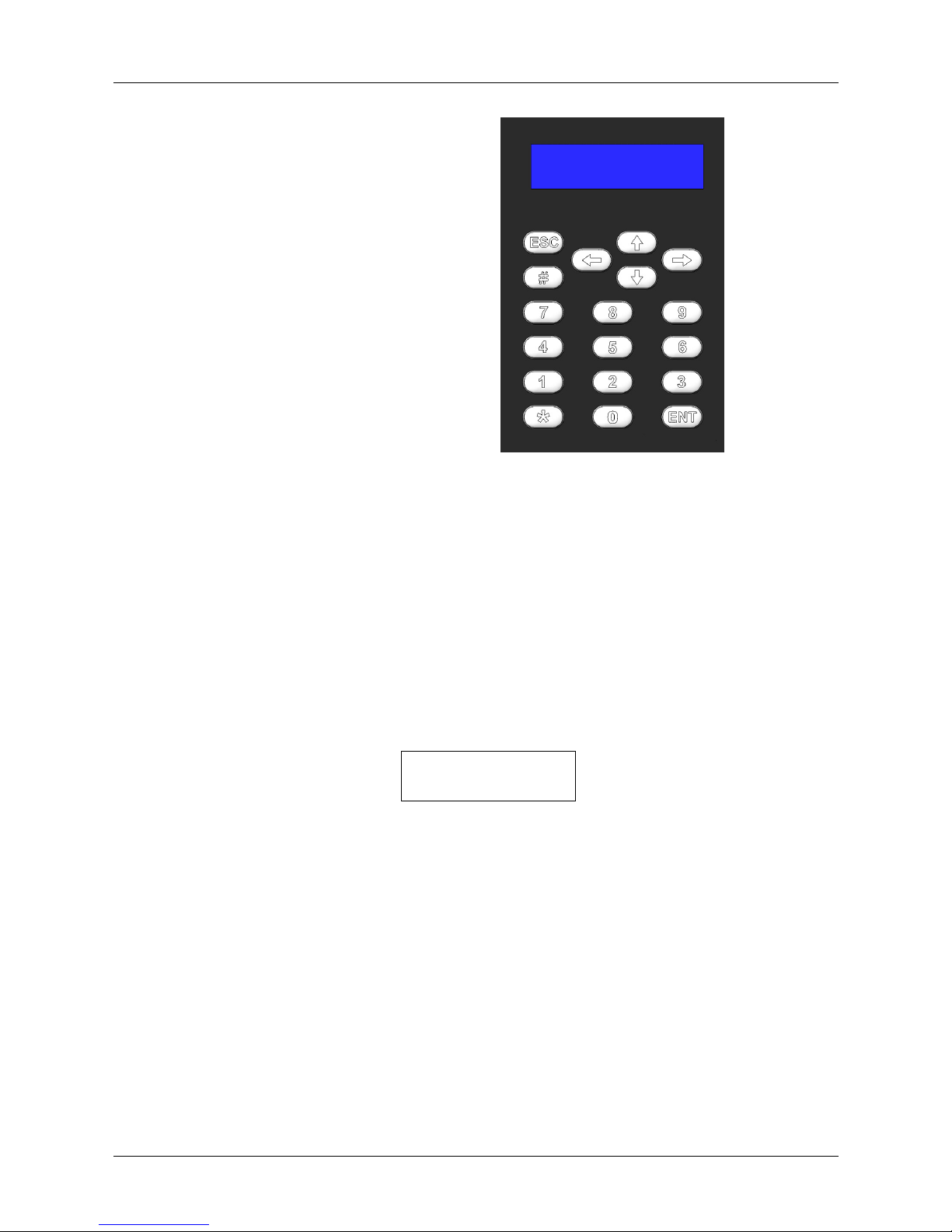
Figure 1 - 1: Control Panel
Overview
The Chilli Dimmers are available
in several versions as shown in
the table on the previous page.
The channels may be patched as
a block or individually to the DMX.
The DMX control port supports
RDM (Remote Device
Management) functionality
(version 7.00 firmware onwards).
Each channel has a manually
adjustable output level.
Each channel can be set to follow
one of four different dimming
laws.
Preheat for individual channels
can be set to between 0% and
20%.
Each channel can be topsetted to
limit its maximum output level.
Twelve programmable memories
using an output grab method.
Individual memories can be
played back, when required.
Editable memory fade times and
channel levels.
Three programmable sequences
using the memories. Sequences
can be played back, when
required.
DMX fail mode (DMX Hold, Fade
to Black or Fade to Memory).
Reset Dimmer function.
DMX status indication.
Alarm Input - alarm state and
alarm messages (if networked).
HF ballast controller options of 010V analogue or DSI (410 HF and
1210HF versions only).
Lock function to prevent menu
access.
Stand alone or network modes.
Areas assignable to channels in
network mode, allowing memory
and sequence playback on an
area basis.
Front Panel Controls
The control panel provides the
user interface to the Chilli
Dimmer.
LCD Screen
The LCD screen comprises two
lines of 16 characters. In this
manual, the screen is shown as
follows:
DMX: 1
Temp: OK
Numeric Keys
The numeric keys (0 - 9) are
used for entering numerical data
(eg channel number, manual
levels, DMX addresses etc.)
Star Key
The function of the star key (*) is
not yet defined.
Hash Key
The Hash key (#) is used to
toggle the channel level between
0% and 100% in Manual Control
or Edit memory.
Cursor Keys
The cursor keys are used to
scroll across menus, select
options from a defined range, or
increase or decrease the value
in a selected field.
The Up and Right keys are
functionally identical.
The Down and Left keys are
functionally identical.
Enter Key
The Enter key (ENT) is used to
confirm numeric data entry,
move down menu structures,
confirm operations etc.
Escape Key
The Escape key (ESC) is used
to escape from the current menu
to the menu level above.
Installation
Chilli Dimmer 73-853-00 Issue 8 Page 5 of 30
Installation
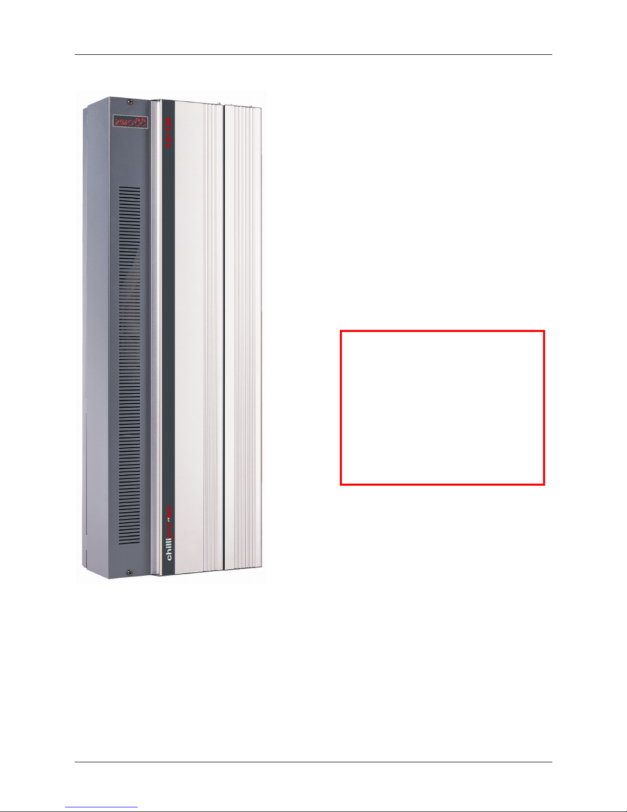
Figure 2 - 1: The Chilli Pro 12 Channel Dimmer
Introduction
This chapter deals with installing the Chilli Dimmer
and includes the following sections:
• Mounting the Dimmer
• Connecting to the Mains
• Load Connections
• DMX Connection
• Alarm Input Connection
• Chilli Network (Chilli Net)
• Network Terminals
• Termination Resistors
• Network Connection
WARNING
DISCONNECT THE
DIMMER FROM THE
MAINS SUPPLY
BEFORE REMOVING
THE FRONT COVER.
Installation
Chilli Dimmer 73-853-00 Issue 8 Page 6 of 30
4 Channel Dimmers
This section covers the installation
of the 4 X 10 and 4 X 10 HF
dimmers.
Mounting the Dimmer
The dimmer is provided with four
6mm diameter fixing holes for wall
mounting.
The mounting holes can be
accessed by undoing the screws
on the front cover and removing it.
The unit should be installed in a dry
ventilated location, where ambient
temperature and humidity are
within the operating range of the
unit (see chapter 4 for details).
The dimmers have ventilation slots
on all sides to allow convection
cooling and under no
circumstances should these be
blocked.
Recommended minimum
clearance around the dimmers is
100mm each side of the unit and
50mm above and below the unit if
trunking with a depth greater than
50mm is used.
Connecting to the Mains
A separate isolator and secure
mains earth are required. Phase to
neutral voltage must not exceed
255V.
The dimmers are supplied with a
selection of knockouts on the top
of the dimmer for mains cable
entry.
Appropriate cable glands should be
fitted to the knockout holes
provided to protect the mains
cables from damage.
The 4 channel dimmers in the
range are designed to run on a
nominal 230V 50Hz single phase
supply.
Ensure that all the mains
connections are fully tightened and
lockwashers are used where
supplied.
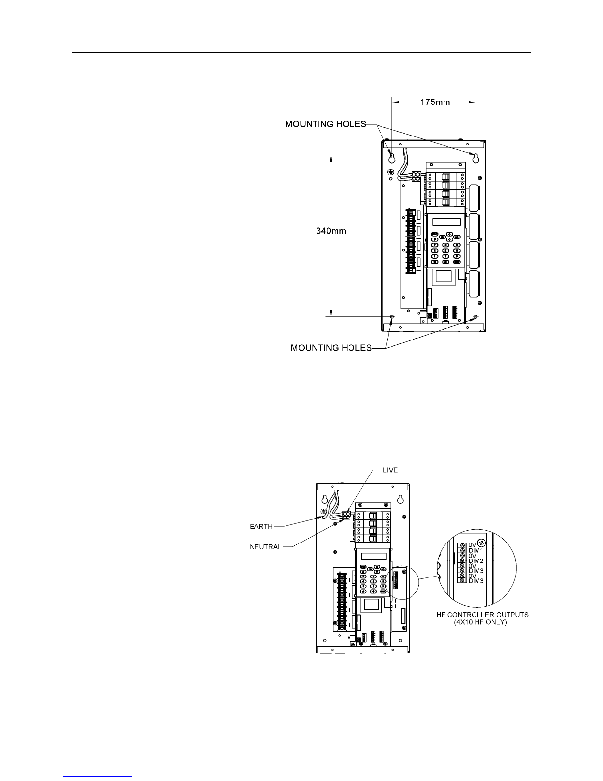
Figure 2 - 2: Chilli Pro 4 Channel Dimmer
Figure 2 - 3: Chilli Pro 4 Channel Dimmer

Installation
Chilli Dimmer 73-853-00 Issue 8 Page 7 of 30
Load Connections
4 Channel Unit
The load cables are connected to
the terminal strips located on the
left hand side of the unit. The
outputs will accept a maximum
6mm2 cable.
Do not use a common neutral for
multiple loads.
4 Channel HF Unit
The switched outputs are
connected to the terminal strips
located on the left hand side of the
unit. The outputs will accept a
maximum 6mm2 cable.
Do not use a common neutral for
multiple loads.
The HF controller outputs are
connected to the terminal strip
located on the right hand side of
the unit and will accept a maximum
2.5mm2 cable.
NOTE - The HF controller
outputs in this product are
electrically isolated from mains
earth and mains phase.
They are only intended for
connection to electronic ballasts
for fluorescent fittings.
They are not intended to control,
and should not be connected at
any time, to any earth referenced
electronics.
Installation
Chilli Dimmer 73-853-00 Issue 8 Page 8 of 30
6 and 12 Channel Dimmers
This section covers the installation
of the 6 X 25, 12 X 10 and 12 X 16
dimmers.
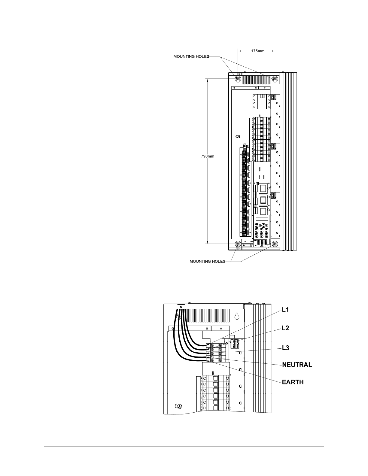
Mounting the Dimmer
The dimmer is provided with four
6mm diameter fixing holes for wall
mounting.
The mounting holes can be
accessed by undoing the screws
on the front cover and removing it.
The unit should be installed in a dry
ventilated location, where ambient
temperature and humidity are
within the operating range of the
unit (see chapter 4 for details).
The dimmers have ventilation slots
on all sides to allow convection
cooling and under no
circumstances should these be
blocked.
Recommended minimum
clearance around the dimmers is
100mm each side of the unit and
50mm above and below the unit if
trunking with a depth greater than
50mm is used.
Connecting to the Mains
A separate isolator and secure
mains earth are required. Phase to
neutral voltage must not exceed
255V.
The dimmers are supplied with a
selection of knockouts on the top
of the dimmer for mains cable
entry.
Appropriate cable glands should be
fitted to the knockout holes
provided to protect the mains
cables from damage.
The 6 and 12 channel dimmers in
the range are designed to run on a
nominal 230V 50Hz 3-phase
supply.
Ensure that all the mains
connections are fully tightened and
lockwashers are used where
supplied.
Other wiring options are available please consult the factory for
details.
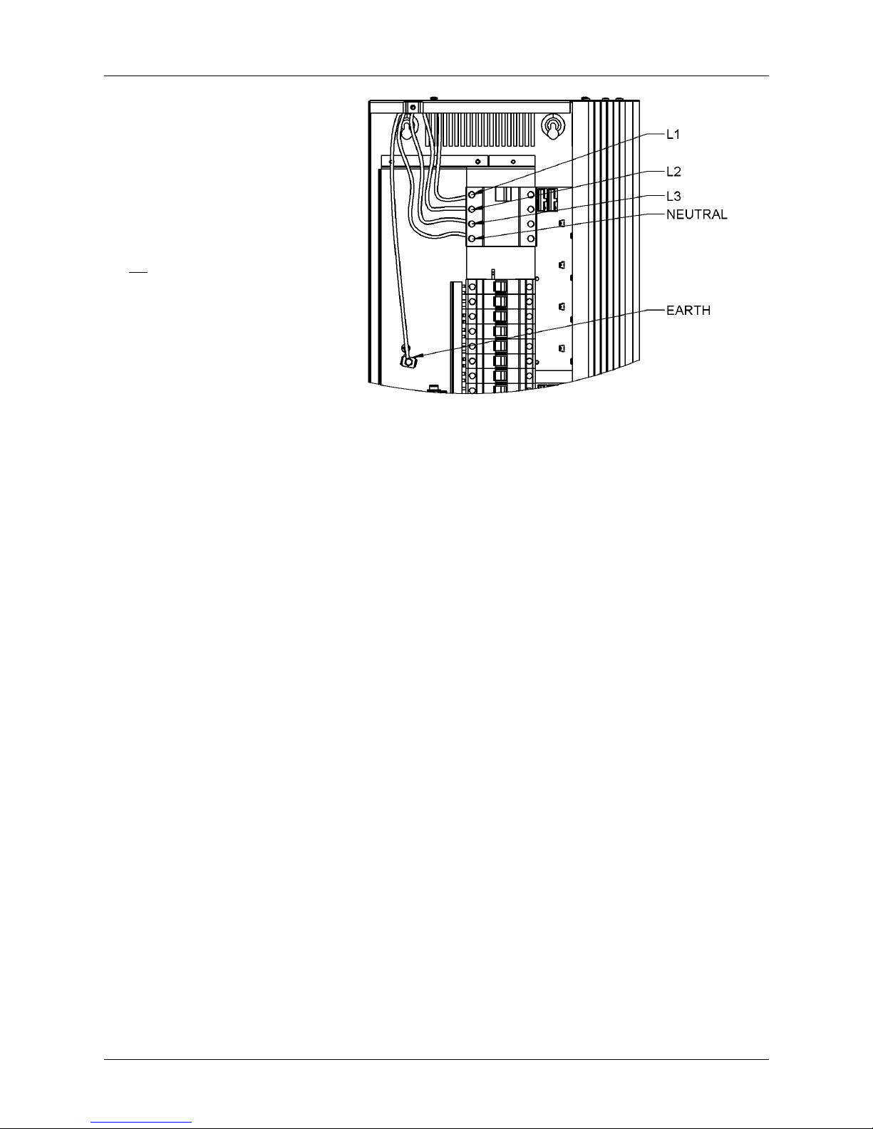
Figure 2 - 4: Chilli 6 or 12 Channel Dimmer
Figure 2 - 5: Chilli 6 or 12 Channel Dimmer (No RCD)
Installation
Chilli Dimmer 73-853-00 Issue 8 Page 9 of 30
Load Connections
6 and 12 Channel Units
The load cables are connected to
the terminal strips located on the
left hand side of the unit.
The outputs are phase interleaved
and the terminals are labelled L1,
E, N1, L2, E, N2, etc. and will
accept a maximum 6mm2 cable.
Do not use a common neutral for
multiple loads.
Figure 2 - 6: Chilli 6 or 12 Channel Dimmer (3 Phase RCD)
 Loading...