

Xeos Technologies Inc. Onyx User Manual

Onyx User Manual
Miniature Iridium Asset Tracker with Relay Function
Version 5.2
May 2018

Email
support@xeostech.com
Phone
(902) 444 7650
Fax
(902) 444 7651
Website
www.xeostech.com
Version No.
Date
Description
1.0
Jun 2013
Base document
2.0
Aug 2014
Updated format, included relay instructions
3.0
Nov 2014
Updated commands
3.1
Jan 2015
Updated with Onyx-R and I information
3.2
Feb 2015
Added info regarding in-motion mode
3.3
Mar 2015
Added adv. Config. Options in appendices
3.4
Mar 2015
Corrected error in Appendix B
3.5
Apr 2015
Added OEM info
3.6
Nov 2015
Added LV OEM info to Appendix D
3.8
Feb 2016
Added Onyx-M info
4.0
Sept 2017
Document overhaul
5.0
Apr 2018
Added Onyx-WB info, drawings, additional commands
5.1
Apr 2018
Added Understanding Position Information Section
5.2
May 2018
Rewrote Appendix F, Added I and P-type messages
Xeos Technologies Inc.
36 Topple Dr.
Dartmouth, Nova Scotia
Canada
B3B 1L6
Shipped From
Contact Us
Specifics
This manual version is written with respect to Onyx Firmware build 3595. To acquire the latest
firmware for your device, contact support@xeostech.com
Version History
Onyx User Manual Version 5.2 2

Table of Contents
Shipped From .................................................................................................................................. 2
Contact Us ....................................................................................................................................... 2
Specifics ........................................................................................................................................... 2
Version History ................................................................................................................................ 2
General Description ........................................................................................................................ 6
Theory of Operation........................................................................................................................ 6
Operating Instructions .................................................................................................................... 6
Setting up your Iridium Account ................................................................................................ 6
Onyx Variants .................................................................................................................................. 7
Onyx ............................................................................................................................................ 7
Onyx-I ......................................................................................................................................... 7
Onyx-R ........................................................................................................................................ 7
Onyx-LV OEM ............................................................................................................................. 7
Onyx-M ....................................................................................................................................... 8
Onyx-WB ..................................................................................................................................... 8
Deployment of the Onyx ................................................................................................................. 9
Antennas .................................................................................................................................... 9
Powering the Onyx .......................................................................................................................... 9
Standard Onyx ............................................................................................................................ 9
Onyx-I ....................................................................................................................................... 10
Onyx-R ...................................................................................................................................... 10
Onyx-M ..................................................................................................................................... 10
LED Indicators ............................................................................................................................... 10
Device Status LEDs ................................................................................................................... 10
Recharging the Onyx-R/M ........................................................................................................ 11
Serial Interface .............................................................................................................................. 11
Things to Remember ................................................................................................................ 11
Testing Your Installation ........................................................................................................... 12
Communicating with the Onyx ..................................................................................................... 12
Sending Commands via Email .................................................................................................. 12
Command Format ................................................................................................................ 12
Onyx User Manual Version 5.2 3

Command Structure ............................................................................................................ 12
The Unlock Code .................................................................................................................. 13
Sending the Command ........................................................................................................ 13
Sending Commands Using Xeos Online.................................................................................... 14
Setting up to Send ............................................................................................................... 14
Understanding Position Information ............................................................................................ 15
Iridium Doppler position .......................................................................................................... 15
Global Positioning System ........................................................................................................ 17
Configuration of the Onyx............................................................................................................. 18
Onyx Mode Diagram ................................................................................................................ 18
Summary .................................................................................................................................. 18
Onyx Timer Intervals ..................................................................................................................... 19
Setting timers ........................................................................................................................... 19
In-Motion Timer ....................................................................................................................... 20
In-Motion Threshold ................................................................................................................ 20
Additional Settings, Commands, and Messages ........................................................................... 21
Version (Type V) ....................................................................................................................... 21
Position (Type P) ....................................................................................................................... 21
Information Message (Type I) .................................................................................................. 22
Settings ..................................................................................................................................... 22
Timer ........................................................................................................................................ 23
Lifetime Stats ............................................................................................................................ 23
Stats .......................................................................................................................................... 24
Message Enable ............................................................................................................................ 24
Digital Output Pin .......................................................................................................................... 25
Encryption ..................................................................................................................................... 25
Generating your Key ................................................................................................................. 25
Enabling Encryption.................................................................................................................. 26
Setting Up Encryption on XeosOnline ...................................................................................... 26
Other Commands .......................................................................................................................... 27
Appendix A: Firmware Update Procedure .................................................................................... 28
Introduction.............................................................................................................................. 28
Process ..................................................................................................................................... 28
Onyx User Manual Version 5.2 4

Requirements ........................................................................................................................... 28
Loading Firmware into the Onyx .............................................................................................. 28
Testing the Onyx ....................................................................................................................... 29
Installing the Serial to USB Driver ............................................................................................ 29
Appendix B: Pinout Diagrams ....................................................................................................... 30
Onyx, Onyx-R ............................................................................................................................ 30
Onyx-M ..................................................................................................................................... 30
Onyx-WB ................................................................................................................................... 30
Onyx-OEM ................................................................................................................................ 30
Appendix C: Mechanical Drawings ................................................................................................. 1
Onyx ............................................................................................................................................ 1
Onyx-I ......................................................................................................................................... 2
Onyx-R ........................................................................................................................................ 3
Onyx-M RH ................................................................................................................................. 4
Onyx-WB ..................................................................................................................................... 5
Onyx OEM ................................................................................................................................... 6
Onyx Low Voltage OEM .............................................................................................................. 7
Appendix D: Cable Drawings ........................................................................................................... 8
Appendix E: Specifications .............................................................................................................. 1
Standard Onyx, Onyx-WB, Onyx-I .............................................................................................. 1
Onyx-R, Onyx-M (Low Voltage) .................................................................................................. 1
Shared Characteristics ................................................................................................................ 1
Appendix F: Relay Function............................................................................................................. 2
Basic Functionality ...................................................................................................................... 2
Serial Relay ................................................................................................................................. 2
Mobile Originated SBD (From Device) ................................................................................... 2
Mobile Terminated SBD (To Device) ..................................................................................... 4
Settings ....................................................................................................................................... 5
Appendix G: Warranty, Support and Limited Liability .................................................................... 6
Onyx User Manual Version 5.2 5

General Description
The Onyx is a miniaturized asset tracking beacon which continuously monitors for asset location
and reports location and sensor information via the Iridium satellite network. Onyx makes use of
the bi-directional, global, real time Iridium Satellite Short Burst Data (SBD) network in
combination with GPS position location. Onyx’s extremely small size and form factor make it
easy to install quickly for overt installations or hide in a wide variety of locations for covert
tracking or custom concealments.
Inside the Onyx is a 9603 Iridium satellite Short Burst Data core radio transceiver, a specialized
low-power Xeos digital controller with GPS, Iridium antenna, GPS antenna, and complex
accelerometer for motion detection.
While the Onyx is intended for both covert and overt mobile deployments. Xeos Technologies
Inc. (Xeos) manufactures other products for fixed location monitoring and remote tracking and
surveillance.
The Onyx also features a built-in relay function for the remote control and retrieval of serial
devices, such as sensors or cameras.
See www.xeostech.com for details or call (902)-444-7650.
Theory of Operation
The Onyx is intended for continuous and/or periodic monitoring of high value assets globally. The
Onyx can facilitate instant and accurate location of assets for recovery or monitoring purposes.
The internal GPS determines location which is stored on board the Onyx. An Iridium modem
provides two-way communications for retrieval of data, live tracking and sending commands to
the remote tracker. The deployment is facilitated by the miniature device which has both GPS
and Iridium antennas on board.
Operators can communicate with the Onyx via Iridium using Xeos Online or via email commands
when appropriately configured. Status information can be obtained, including the health of the
GPS system and battery voltage. Timings are settable remotely and can be modified as the nature
of the tracking or monitoring operation changes.
The internal relay function allows the Onyx to be piggy-backed to an external serial device and
used as a communications interface for that device. For instance, you may wish to send
commands to a remote camera or receive data from a temperature sensor.
Operating Instructions
Setting up your Iridium Account
Onyx makes use of the Iridium satellite system’s (www.iridium.com) Short Burst Data (SBD)
service for the 9603 transceiver. This service is a global, two-way, real-time, email-based data
delivery service that has a maximum outbound (from Onyx) message size of 340 bytes and a
maximum inbound (to Onyx) message size of 270 bytes.
Onyx User Manual Version 5.2 6
Onyx end users must set up an approved data delivery account with their preferred service
provider. Xeos is an Iridium VAR and can provide Iridium service if you wish.
Setting up service requires the International Mobile Equipment Identity (IMEI) number. Each
9603 has a unique IMEI number that must be registered with a preferred service provider. Xeos
will make these numbers available when the product is delivered.
Each IMEI number is capable of being associated with up to five (5) unique email addresses. This
may vary between service providers. When registering your IMEI number, please provide the
service provider with the temporary Xeos testing account email address.
This account is: xeosbeaconb@gmail.com.
Setting up this email address allows for better technical support during the initial learning period
for the product. Once service is activated, please notify the technical support team.
While any email application can be used to send and receive messages between the user and the
Onyx, Xeos Online is the easiest way to manage and monitor multiple Onyx devices. Xeos Online
presents the information in a readable format and displays it on street level maps.
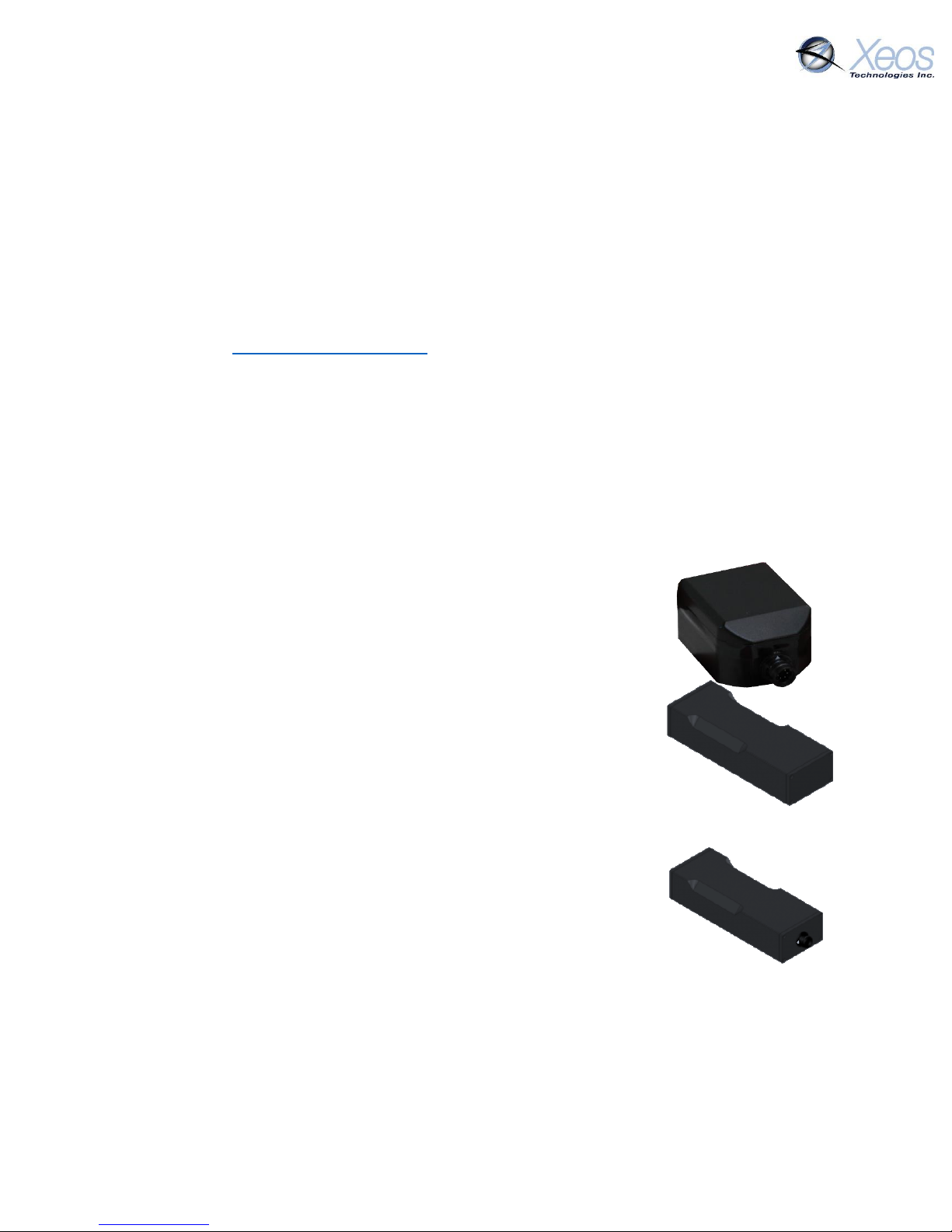
Onyx Variants
Onyx
The standard Onyx has no internal power source. It requires an
external power supply of 7 to 24 Volts.
Onyx-I
The Onyx-I has an internal power source, consisting of four 3 Volt
CR123A Lithium non-rechargeable batteries in series. This model has
a larger profile than the standard Onyx but functions identically, save
for the lack of an external connector. An additional magnet plate can
be added to the bottom of the enclosure for quick deployment.
Onyx-R
The Onyx-R also has an internal power source, consisting of a
rechargeable 3.6 Volt Lithium-Ion battery pack. This model also has a
larger profile than the standard Onyx as well as charging indicator
LED’s. A front connector is used for diagnostics and charging. Like with
the Onyx-I, an additional magnet plate can be added to the bottom of
the enclosure for quick deployment.
Onyx-LV OEM
The Onyx-LV OEM includes an Onyx LV board as is with the Onyx-R. However, customers must
supply their own power supply of between 3.3 and 5.5 Volts. Serial communication is possible
with the supplied programming cable. See Appendix D: OEM LV Programmer.
Onyx User Manual Version 5.2 7
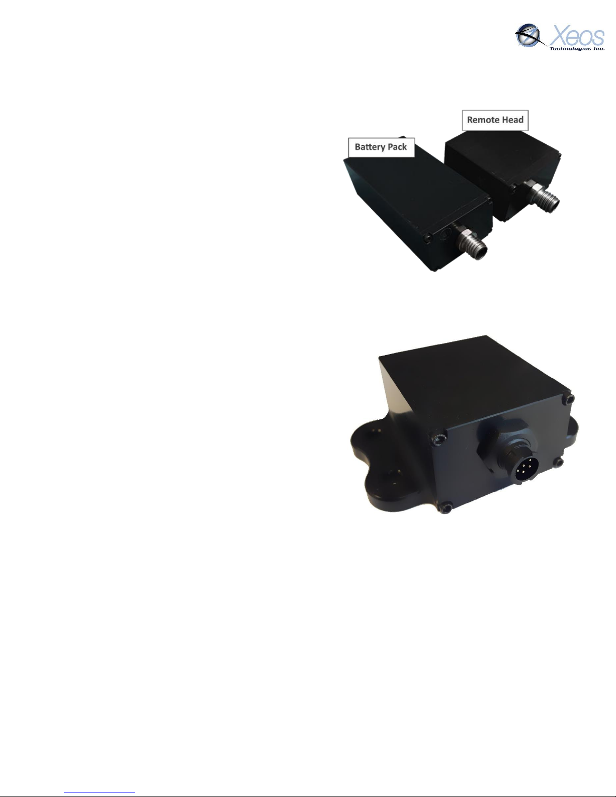
Onyx-M
The Onyx-M is the marine variant of the Onyx and is
submersible to 10m. The Remote-Head and Battery
pack are both waterproof, but cables should remain
attached while underwater to prevent pin corrosion.
The Onyx-M Remote-head can be treated identically
to an Onyx when considering installation. Like the
Onyx, the Onyx-M’s programming cable can power
the unit when connecting serially to a PC for
diagnostic purposes.
The magnet cups on the bottom of the Remote-head
and Battery pack are designed for 5/8” diameter
magnets, which are not included.
Onyx-WB
The Onyx-WB (Work Boat) is the marine variant of the
Onyx designed for static mounting. The enclosure of
the Onyx-WB is rated IP-67 enclosure to prevent
water ingress.
The Onyx-WB Remote-head can be treated identically
to an Onyx when considering installation. Like other
Onyx variants, the Onyx-WB’s programming cable can
power the unit when connecting serially to a PC for
diagnostic purposes.
Wings on the sides of the WB’s enclosure allow for
mounting to frames of objects, while the twist-on
cable prevents unintentional unlatching of the power
supply from the device.
Onyx User Manual Version 5.2 8

Deployment of the Onyx
The Onyx contains GPS and Iridium antennas. The only external requirement is a power source.
Deploying the Onyx requires the following:
An Onyx with Iridium service activated (using IMEI provided by Xeos)
An external power source from 7 – 32 VDC (Standard Onyx only)
(Optional) An external serial device to be managed via the Onyx
Antennas
To deploy the Onyx, ensure that the surface with the beveled edge, which is where the antennas
are located, has a clear view of the sky. For a covert deployment, the antenna surface must not
be obstructed by metal or wood. Thick amounts of other materials may also cause interference.
Testing of covert installation locations is strongly recommended.
Powering the Onyx
Standard Onyx
While the power source can be between 7 & 24 VDC, it is recommended that users not use a
power source very close to either extreme. Once the power supply dips below 7V,
communication may not be possible with the Onyx.
If the power supply is subject to power surges, it may not be advisable to use a power supply
with an average voltage of 24 VDC to avoid damaging the internal circuitry of the Onyx.
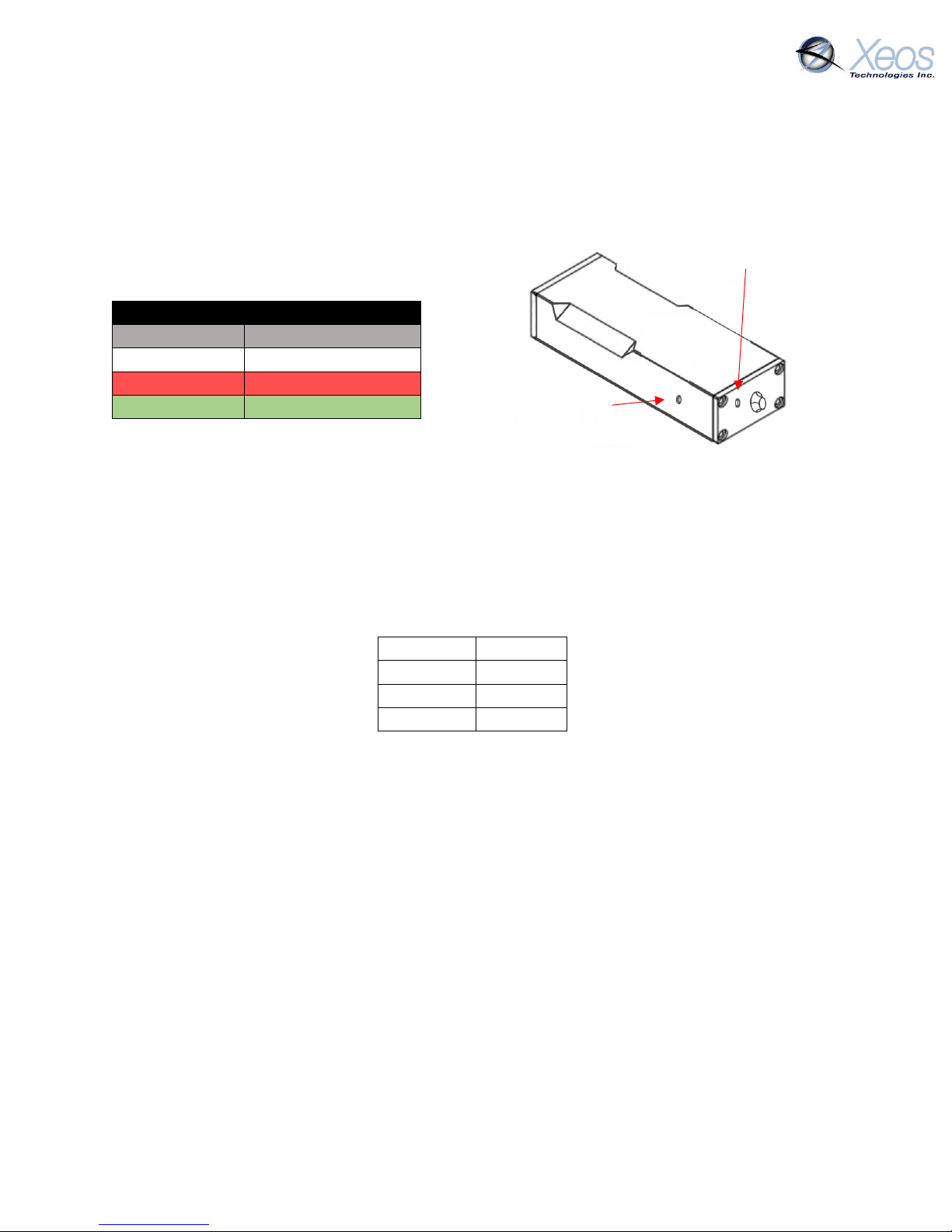
To create a custom battery pack or make your own flying lead assembly, please refer to the pinout diagram below.
Onyx Pin-out Diagram HR-30 (PN HR30-6R-6PD)
(View into Onyx connector)
Onyx User Manual Version 5.2 9

Pin
Purpose
1
Ground (-) battery input
2
Digital I/O
3
Data output from Onyx
4
Data input to Onyx
5
5V USB power input
6
Positive (+) battery input (12VDC Nominal)
Unit Status LED
Turn On
Swipe Magnet back and forth across topside until LED is solid green
Turn Off
Swipe magnet back and forth across topside until LED is solid red
Status
Swipe magnet once across topside (red is off, green is on)
The battery pack will use pins 6 (V+) and 1 (V-). Reversing the polarity on the pins could cause
damage to the unit. The remaining pins are for use with a serial device, therefore are not used
with the battery pack.
The LV OEM programming cable differs from the standard Onyx cable, see Appendix D: OEM LV
Programmer for more information.
Onyx-I
The Onyx-I uses a non-rechargeable battery pack, and therefore does not have a charging LED.
Equipped with 4 3-Volt CR123A Lithium batteries in series, nominal voltage is identical to the
standard Onyx at 12VDC. The Status LED functions identically to the Onyx-R and M, and is in the
same location.
Onyx-R
The Onyx-R features a hard-wired internal Lithium battery pack at a nominal voltage of 3.6V.
Using the front connector of the Onyx-R, the device can be recharged and redeployed.
Onyx-M
The Onyx Marine shares the same battery characteristics and charging capabilities as the OnyxR. Remote-head versions of this device only require the battery pack to be present for charging.
LED Indicators
Device Status LEDs
The Onyx-I, R and M all have a small window on the side of the device to show its on/off status
using an LED. This same LED also pulses red in the event of a self-test failure at start-up.
Onyx User Manual Version 5.2 10
Baud Rate
57.6k
Parity
None
Data Bits
8
Stop Bits
1
Charging LED
LED
Charging Status
Off
Not charging
Red
Battery fault
Green
Normal charging
Recharging the Onyx-R/M
The Onyx-R and Onyx-M both come with charging cables with power and ground leads. The
power supplied should be at 12VDC. A front-mounted window displays the charging status of the
device.
Current draw during charging will decrease until the device reaches max voltage, at which time
the charging LED will shut off. Charging LED
Status LED
Note: The Onyx-M’s Charging LED is located on the battery pack, while the Status LED is on the
side of the Onyx-M’s head, in the same manner as the Onyx-R’s LEDs.
Serial Interface
Pre-programming of the Onyx is not required since it is pre-configured for most tracking scenarios
and configurable settings can be changed over the Iridium link. However confirmation of settings
can be done via an Onyx diagnostic cable through a terminal emulator using these settings:
Note: USB connection is not sufficient to power the Iridium system on the Onyx and will therefore
always fail this check. Sending any character to the Onyx bypasses this check to move onto
configuration.
Things to Remember
The configuration of the Onyx is saved in flash memory. Any changes made will be saved,
even if the power is removed and reapplied later.
As soon as power is applied to the Onyx, it will attempt to get a GPS fix and transmit a
report. Once it successfully makes that report, it will go to “sleep” for 1 hour according to
the default settings. If users need to apply power prior to deployment position and with
a view of the sky during a covert installation, one of two things must be done:
1. Trigger the motion sensor once power is applied by continuously shaking the
device for 1 minute. The interval will change to taking location fixes every 20
seconds and reporting every 1 minute. It will stay in this mode for five minutes
which will allow time to finalize the install and test it.
Onyx User Manual Version 5.2 11
2. Before installing the device, send a message via Xeos Online to change the normal
operating parameters to a shorter time frame, for instance, GPS fix and SBD report
every 1 minute. Proper installation can then be quickly confirmed. Don’t forget to
set the parameters for your preferred no-motion mode once deployed.
Some types of installation will not trigger the motion sensor since it senses vibration.
Installation in a padded cushion, on a person or in a non-structural location on a vehicle
may not register motion and may require changes to the reporting parameters according
to operational needs.
Testing Your Installation
Test the installation by checking the email addresses to which the Iridium account is sending
notifications or Xeos Online. Xeos Online will display the last known position of the device as well
as the time stamp of the GPS position.
Communicating with the Onyx
Sending Commands via Email
To receive commands from the Iridium network, the device in use must have a clear view of the
sky. If the device is unable to communicate with the Iridium network, commands will remain
queued for five days.
Command Format
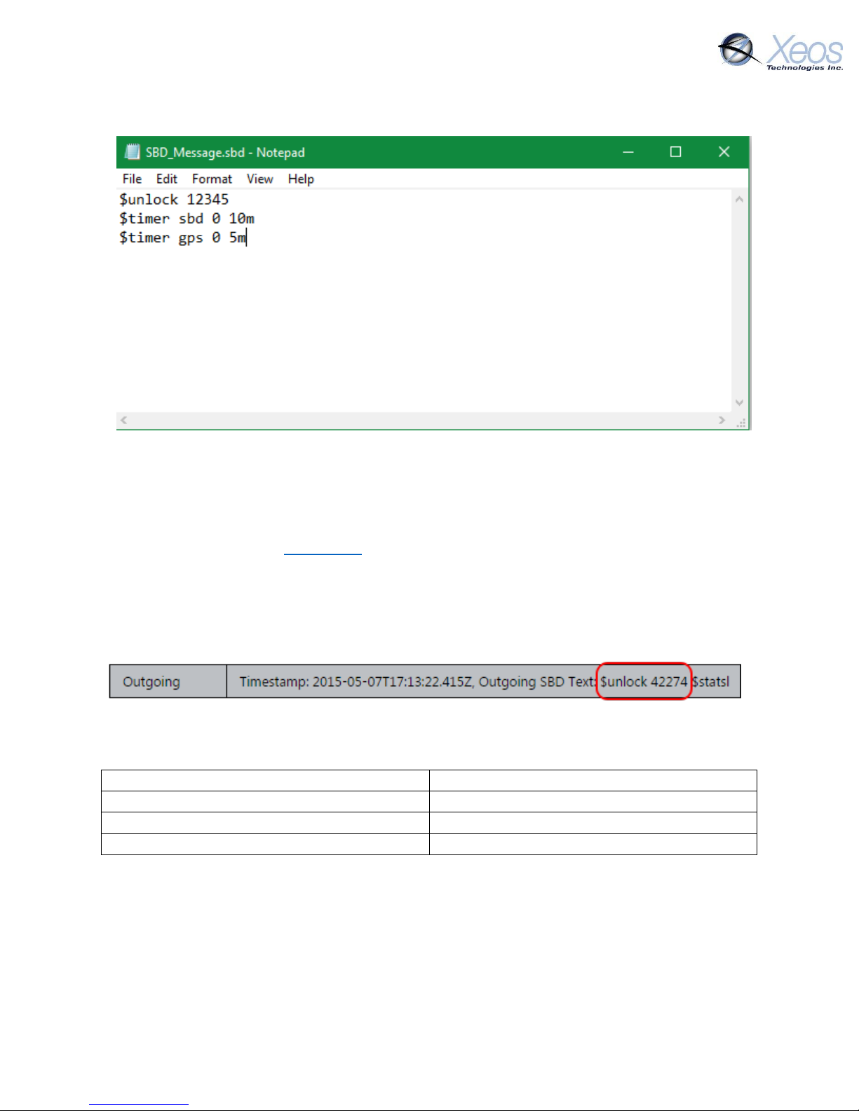
Creating the File
To create an SBD command, open a new file in a text editor (ex. Notepad) and save it using the
.sbd extension. Make sure the Save as type option is set to All Files to achieve this.
Command Structure
Commands must be structured in the following way:
1. Each command MUST have a dollar sign ($) before each command.
2. The unit’s unlock code in the following format: $unlock XXXXX
where XXXXX is the unit’s five digit unlock code.
Onyx User Manual Version 5.2 12
To
data@sbd.iridium.com
Subject
The target device’s IMEI
Body
Empty
Attachments
The .sbd file
3. A list of commands, one command per line.
The Unlock Code
SBD commands without an unlock code will be ignored by devices that require it. These devices
include the Apollo, XMI, Onyx, Rover, and Osker. The unlock code is generated by the device itself
and can be retrieved from XeosOnline, or the unit can be queried for its unlock code by sending
$unlock to the device as a command. The device will respond by sharing the 5-digit code with its
provisioned destinations.
Navigate to your unit and click on the Message Log Tab. The unlock code can be seen in the
most recent outgoing messages.
Sending the Command
To send an sbd command, create a new email message with the following fields:
Onyx User Manual Version 5.2 13
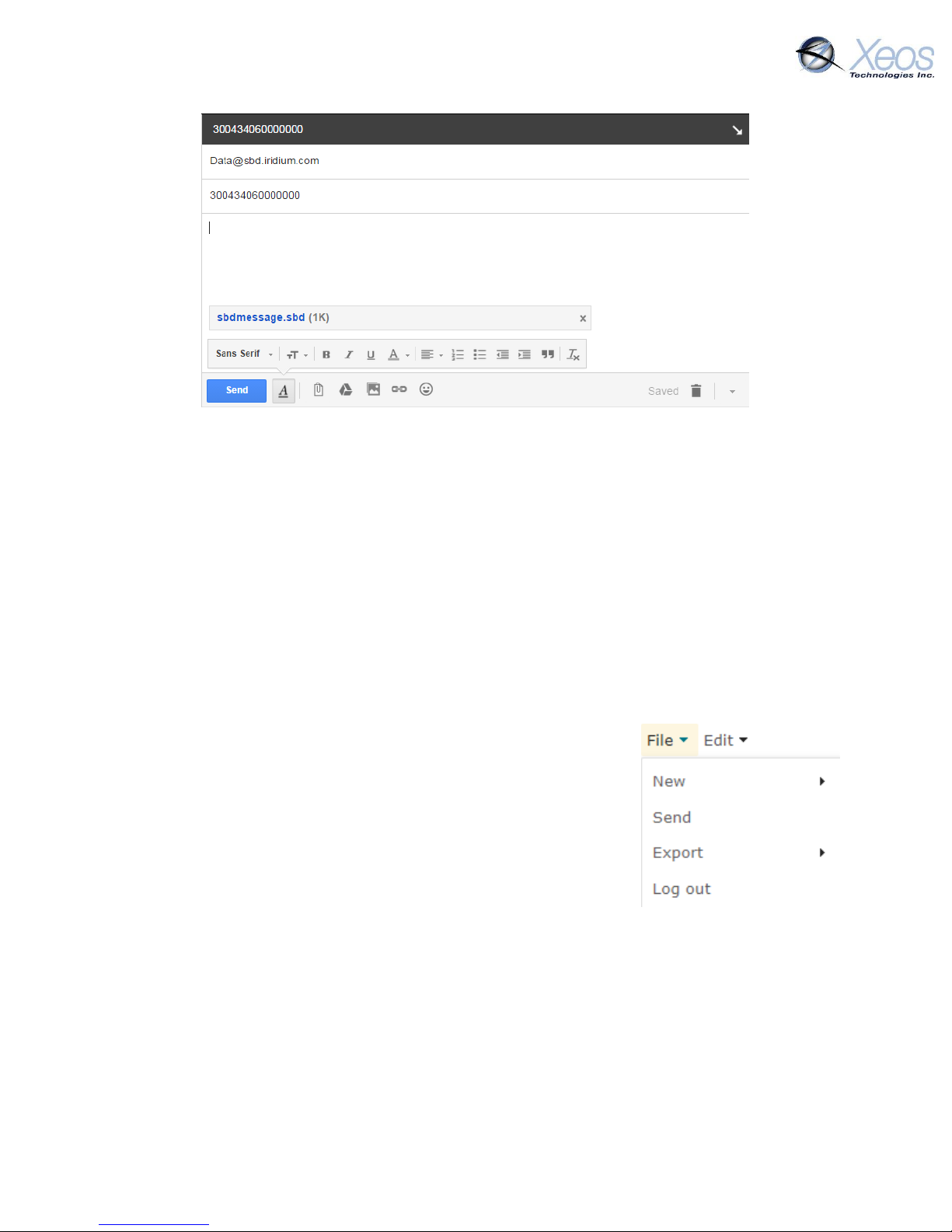
A confirmation will be immediately returned from the Iridium Gateway from the address
sbdservice@sbd.iridium.com indicating that your message is now in the message queue. It will
be delivered to the device during its next Iridium check.
Commands can be sent from any email address, but responses will be returned only to email
addresses on the unit’s forwarding list.
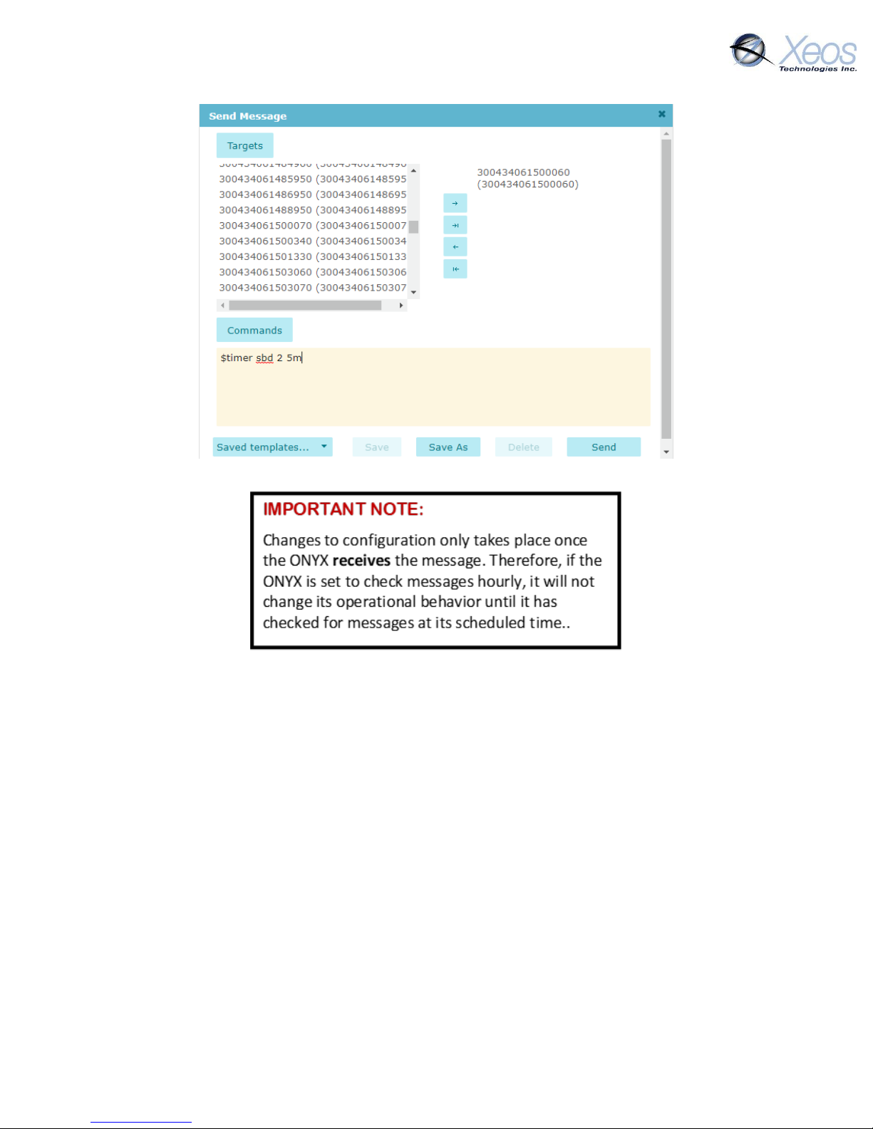
Sending Commands Using Xeos Online
Before using Xeos Online make sure that your account has been set up and your device added to
your organization. Contact activations@xeostech.com for more information.
Setting up to Send
Navigate to the Send Command window.
From the Home Tab, choose File > Send
Select the units you wish to target with commands and move them
over to the right-hand target list using the -> button.
Type your command(s) into the command box and press Send.
Remember to include the dollar sign ($) ahead of each command and
enter each command on a separate line.
Outgoing messages will appear in the Message Log for the commanded device.
Onyx User Manual Version 5.2 14
Understanding Position Information
There are two types of position information which will be sent via the Iridium Gateway.
Iridium Doppler position
The Iridium Gateway calculates the Iridium transceivers’ position on earth when it receives a
transmission, using Doppler technology. As a result, it is often very inaccurate. This location is
only visible to users getting emails directly from the device, as opposed to emails forwarded by
XeosOnline. An example of a “raw” Iridium message via email is below and will always have the
IMEI of the device in the subject line, regardless of its name on XeosOnline.
Onyx User Manual Version 5.2 15
 Loading...