

Page 1

Rover User Manual
Surface Iridium Satellite Beacon with GPS Location
Version 3.0
July 2019
Page 2
Email
Phone
(902) 444-7650
Fax
(902) 444-7651
Website
www.xeostech.com
Version No.
Date
Description
1.0
Oct 2013
Original Document
2.0
Jan 2015
Rewrite, added information on updating
2.5
Oct 2017
Document overhaul
2.6
Dec 2017
Standardized Commands and Bluetooth info
2.6.1
Jan 2018
Watch Circle information edits
2.6.2
Jan 2018
Fixed error in default timers of Timer 3
2.7
Feb 2018
Added further details to Bluetooth info (New BT update)
2.8
Apr 2018
Rewrote Understanding Position Information section
2.9
Aug 2018
Added changes for version 4170, encryption
3.0
July 2019
Overhaul; messages expanded, alarm mode tips, flash memory
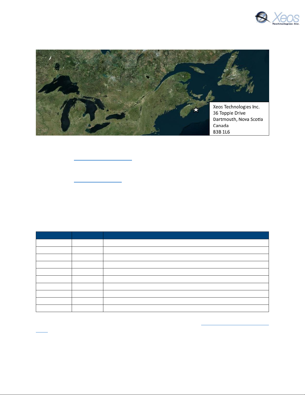
Shipped From
Contact Us
Specifics
This manual version is written with respect to Rover firmware build 4170. If you wish to acquire
the latest firmware for your device, contact [email protected]
Version History
Regular checks for the latest manual are suggested. Be sure to check Xeos Technologies’ manuals
page to compare versions and download the latest version.
Rover User Manual Version 3.0 2
Page 3

Table of Contents
Shipped From .................................................................................................................................. 2
Contact Us ....................................................................................................................................... 2
Specifics ........................................................................................................................................... 2
Version History ................................................................................................................................ 2
General Description ........................................................................................................................ 6
Theory of Operation........................................................................................................................ 6
Preliminary Setup ............................................................................................................................ 7
Outside Diagram ......................................................................................................................... 7
Setting up an Iridium Account .................................................................................................... 7
Quickstart ........................................................................................................................................ 9
Before using the Rover ............................................................................................................... 9
Power-Up.................................................................................................................................... 9
Battery Installation ................................................................................................................ 9
Magnet ................................................................................................................................... 9
Confirm Transmission ................................................................................................................. 9
Operation ................................................................................................................................... 9
Understanding Position Information ............................................................................................ 10
Iridium Doppler position .......................................................................................................... 10
Global Positioning System ........................................................................................................ 11
Additional Models ......................................................................................................................... 11
ROBY ......................................................................................................................................... 11
On/Off Modes ............................................................................................................................... 12
Using the Magnet ..................................................................................................................... 12
LED Indicators ........................................................................................................................... 12
Messages From the Rover ............................................................................................................ 13
Version ..................................................................................................................................... 13
Position Message ..................................................................................................................... 13
Compressed Binary Position ................................................................................................ 13
ASCII Position (Type P) ......................................................................................................... 14
Status Change Message (Type S) .............................................................................................. 15
Information Message (Type I) .................................................................................................. 16
Rover User Manual Version 3.0 3
Page 4

Orientation Change Message ................................................................................................... 16
Communicating with the Rover .................................................................................................... 17
Sending Commands via Email .................................................................................................. 17
Command Format ................................................................................................................ 17
Command Structure ............................................................................................................ 17
The Unlock Code .................................................................................................................. 18
Sending the Command ........................................................................................................ 18
Sending Commands Using XeosOnline .................................................................................... 19
Setting up to Send ............................................................................................................... 19
Xeos Beacon Bluetooth App ..................................................................................................... 19
Messages to the Rover .................................................................................................................. 20
Settings ..................................................................................................................................... 20
Lifetime Stats ............................................................................................................................ 21
Stats .......................................................................................................................................... 21
Timers............................................................................................................................................ 22
Rover/ROBY Timer Intervals ..................................................................................................... 23
Timer Command ....................................................................................................................... 23
Changing the Timers ............................................................................................................ 24
Watch Circle .................................................................................................................................. 25
Enabling the Watch Circle ........................................................................................................ 25
Setting the Watch Circle ........................................................................................................... 25
Message Enable ............................................................................................................................ 26
Encryption ..................................................................................................................................... 27
Generating your Key ................................................................................................................. 27
Enabling Encryption.................................................................................................................. 28
Setting Up Encryption on XeosOnline ...................................................................................... 28
Flash Memory ............................................................................................................................... 29
Dumping the Flash Memory ..................................................................................................... 29
Deleting the Flash Memory ...................................................................................................... 30
Other Commands .......................................................................................................................... 31
Testing the Rover .......................................................................................................................... 32
Before testing ........................................................................................................................... 32
Testing ...................................................................................................................................... 32
Rover User Manual Version 3.0 4
Page 5

Power-up and Batteries ....................................................................................................... 32
Transmission ........................................................................................................................ 32
Response to commands ...................................................................................................... 33
Inverted Messaging ............................................................................................................. 33
Example .................................................................................................................................... 34
Deployment of the Rover .............................................................................................................. 34
Maintenance ................................................................................................................................. 35
Batteries ................................................................................................................................... 35
Choosing Batteries ............................................................................................................... 35
Adding/Replacing Batteries ................................................................................................. 35
O-Rings ..................................................................................................................................... 36
Removing the ROBY float ......................................................................................................... 37
Recovery and Storage .............................................................................................................. 37
Appendix A: Part Sourcing Summary ............................................................................................ 38
Appendix B: Technical Specifications ............................................................................................ 40
Appendix C: Sample Power Consumption Patterns ...................................................................... 41
Appendix D: Engineering Diagram ................................................................................................ 42
Appendix E: GPS Text Long ........................................................................................................... 43
Warranty, Support and Limited Liability ....................................................................................... 44
Rover User Manual Version 3.0 5
Page 6

General Description
The Rover Surface Iridium satellite mooring location beacon continuously monitors location for
mobile surface assets and/or instrument moorings. Rover makes use of the bi-directional, global,
real time Iridium Satellite Short Burst Data (SBD) network in combination with GPS position
location. Rover’s sleek tubular design and internal dual Iridium/GPS antennas located at each end
cap allow it to be easily retrofitted into a variety of surface mounts. Even surface installations
which capsize may be able to transmit location information.
Inside the Rover is a 9603 Iridium satellite Short Burst Data core radio transceiver, a specialized
low power Xeos digital controller with GPS and Iridium hardware.
Rover is intended for surface deployments and should not be deployed in situations which exceed
100m in depth. Xeos Technologies Inc. (Xeos) manufactures other specific products for either
surface, or subsurface applications to depths of 11,000m.
Theory of Operation
The Rover is intended for providing regular location information on high value assets at the
surface, drifting or moored. After being activated, the Rover is deployed at the surface and begins
sending location messages as per the user settings. The internal battery pack provides over 1500
messages.
Operators can communicate with the surface deployed Rover via Iridium using email commands.
Status information can be obtained, including the health of the GPS system and battery voltage.
Timings are settable, and the default is one message every 3 hours. If you need to make a change
to settings, the Rover will receive the command to change the timing the next time it checks for
messages, as much as 3 hours after the command is sent.
The Rover will continue to send position messages based on the timings, until it is manually
turned off or the battery pack drops below the minimum voltage requirement of 7V.
Due to the location of dual Iridium/GPS antennas at both ends of the enclosure, the Rover will
continue to try and send position messages, even when inverted or capsized.
Rover User Manual Version 3.0 6
Page 7
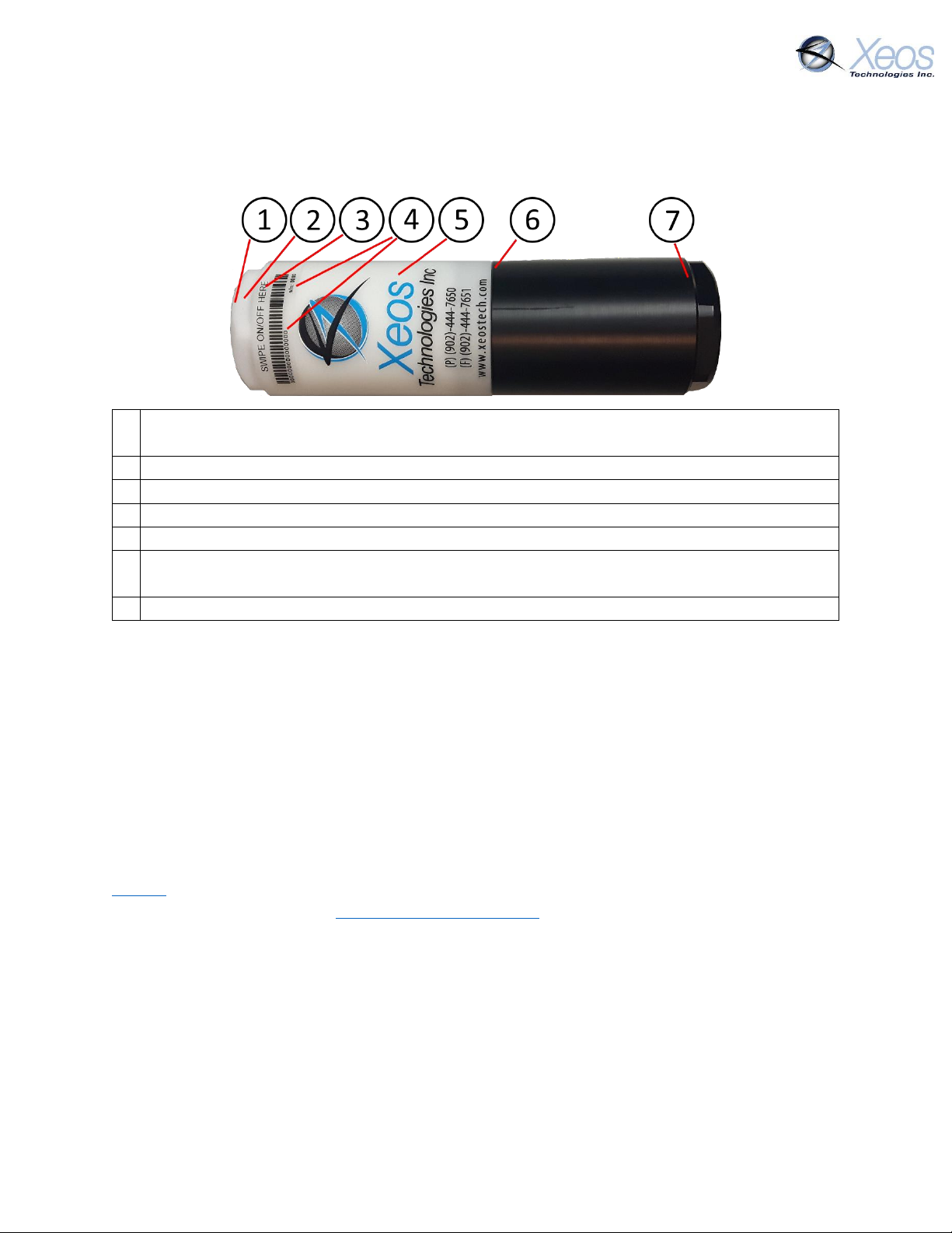
1
The LEDS of the Rover are located here. LEDs illuminate on magnet contact, power-up
and Bluetooth connection
2
The top Iridium and GPS antennae of the Rover are located here
3
The magnet switch for turning the Rover on and off is located behind the label
4
The 15-digit IMEI of the Rover’s Iridium modem and factory serial number is displayed
5
A QR code is available to scan to download the manual on new devices
6
Two sealing O-rings are located in the middle of the Rover. This is where the device is
opened to install batteries
7
The bottom Iridium and GPS antennae of the Rover are located here, used when inverted
Preliminary Setup
Outside Diagram
Setting up an Iridium Account
Rover makes use of the Iridium Satellite Systems’ Short Burst Data (SBD) service for the 9603
transceiver. This service is a global (including the Polar Regions), two-way, real-time and emailbased data delivery service with a maximum outbound (from beacon) message size of 340 bytes
and a maximum inbound (to beacon) message size of 270 bytes.
Rover end users must set up an approved data delivery account with their preferred service
provider. This can only be done once Xeos has provided the user with an International Mobile
Equipment Identity (IMEI) number. Each 9603 modem has a unique IMEI that must be registered
with the preferred service provider. For a list of service providers in your area please contact
Iridium for recommendations. Xeos Technologies is also able to provide Iridium SBD data service
and accounts. Please contact [email protected] for more information.
Each IMEI number is capable of being associated with up to five (5) unique email addresses (this
may vary between service providers). When registering an IMEI number, please provide the
service provider with a temporary Xeos testing account email address.
This account is: [email protected]
This temporary email testing account can be deleted or replaced at any time after delivery of the
Rover. Once the SBD account has been activated, please contact your Xeos representative and
confirm this.
Rover User Manual Version 3.0 7
Page 8

Rover makes use of a simple and robust binary email protocol as the default outgoing message
format. Any email application can be used to send and receive messages to or from the Rover,
however, the messages from the Rover in this format are not human-readable. XeosOnline is a
web-based monitoring system which allows users to view and manage information from the
Rover on a mapping system, as well as view the messages in a human-readable format.
XeosOnline also allows for the creation of multiple kinds of message forwarders which can
forward certain (or all) messages to a group of email addresses in a human-readable form.
Sending messages and changing configuration can be completed through XeosOnline. See
www.xeostech.com or your account manager for more information.
Rover User Manual Version 3.0 8
Page 9
Quickstart
Before using the Rover
Ensure the IMEI of your device is activated through your chosen Iridium
provider and intended message recipients are added to its account ahead
of deployment.
Power-Up
Battery Installation
The Rover automatically turns on once all batteries are installed. The device must
be turned off via magnet or battery removal.
Magnet
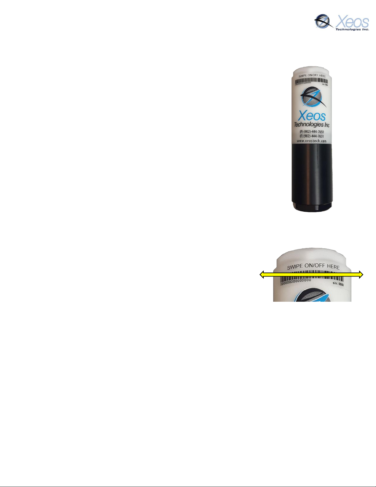
Swipe the magnet slowly along the “SWIPE ON/OFF HERE” label
horizontally until the flashing GREEN LED on the top of the device remains
solid. The green LED will flash again while the device completes powerup.
Confirm Transmission
Turn the device on and place it outside in view of as much of the
sky as possible.
The unit will transmit a power-up message, and transmit one GPS
fix every 10 minutes at default settings within 5 minutes of
power-up for one hour.
Confirm that these messages are being received by your email
and/or XeosOnline.
Operation
When deploying the unit, power it up by swiping the magnet.
Once the unit is confirmed to be on, it is ready to be deployed.
Turn the Rover OFF using the same magnet method as turning ON, with the RED LED in
place of the green.
Rover User Manual Version 3.0 9
Page 10
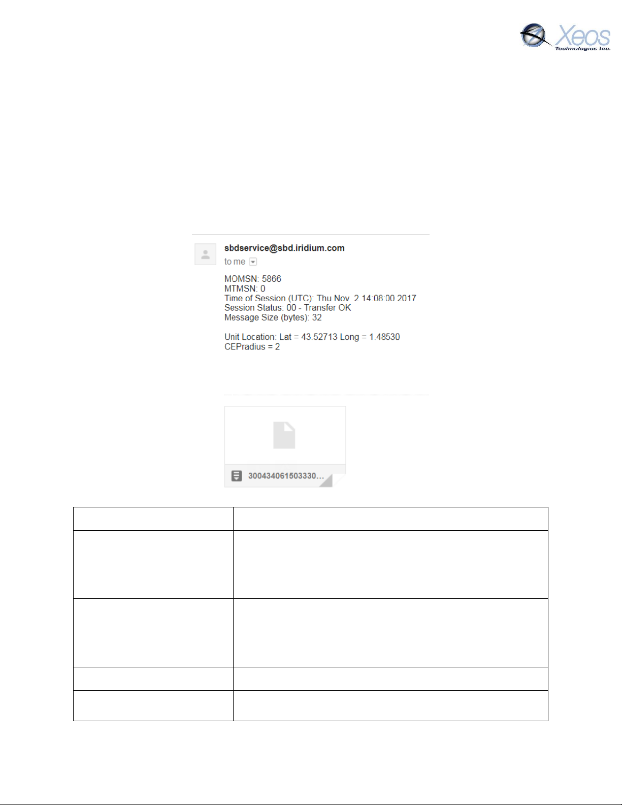
All messages from Iridium devices come from this address.
MOMSN: 5866
Mobile Originating Message Serial Number; each individual
message has its own incrementing serial number. A mobile
originating message is one that comes from the Iridium
device.
MTMSN: 0
Mobile Terminating Message Serial Number; like the MOMSN,
messages to Iridium devices (like commands) also have an
incrementing serial number. Since the message in the
example is from an Iridium device, the MT number is zero.
Time of Session (UTC)
The time the message arrived at the Iridium Gateway
Session Status
Each message will have a code determined by how well the
message was received; codes 00, 01 and 02 are acceptable
Understanding Position Information
There are two types of position information which will be sent via the Iridium Gateway.
Iridium Doppler position
The Iridium Gateway calculates the Iridium transceivers’ position on earth when it receives a
transmission, using Doppler technology. As a result, it is often very inaccurate. This location is
only visible to users getting emails directly from the Rover, as opposed to emails forwarded by
Xeos Online. An example of a “raw” Iridium message via email is below and will always have the
IMEI of the device in the subject line, regardless of its name on XeosOnline.
Rover User Manual Version 3.0 10
Page 11
and will always have their code name (ex. Transfer OK) next to
this number.
Message Size (bytes)
The size of the actual message sent by the Iridium device,
which is in the attachment in the email.
*Unit Location
The Doppler position of the device as estimated by Iridium’s
network. It is NOT the GPS position measured by the device.
*CEPradius = 2
The numerical value of how accurate the above position is;
with a value of 2, This means that using the Lat/Long that the
body has supplied, Iridium is 80% confident (always 80%) that
the device sending the message is within a circle, 2 kilometers
in radius, with the Lat/Long given as the centre of that circle.
The higher the CEPradius value, the larger the circle and
therefore the less accurate that position.
*These items can be enabled/disabled by your Iridium provider if desired.
Global Positioning System
Location information generated by the device itself is embedded in the SBD attachment sent via
the Iridium Gateway and can only be seen through the Xeos Online system or situations where
the position information is sent in a plain-text format (XeosOnline message forwarder or using
the $msgenable command). This position information is accurate to within several feet of the
true position.
Additional Models
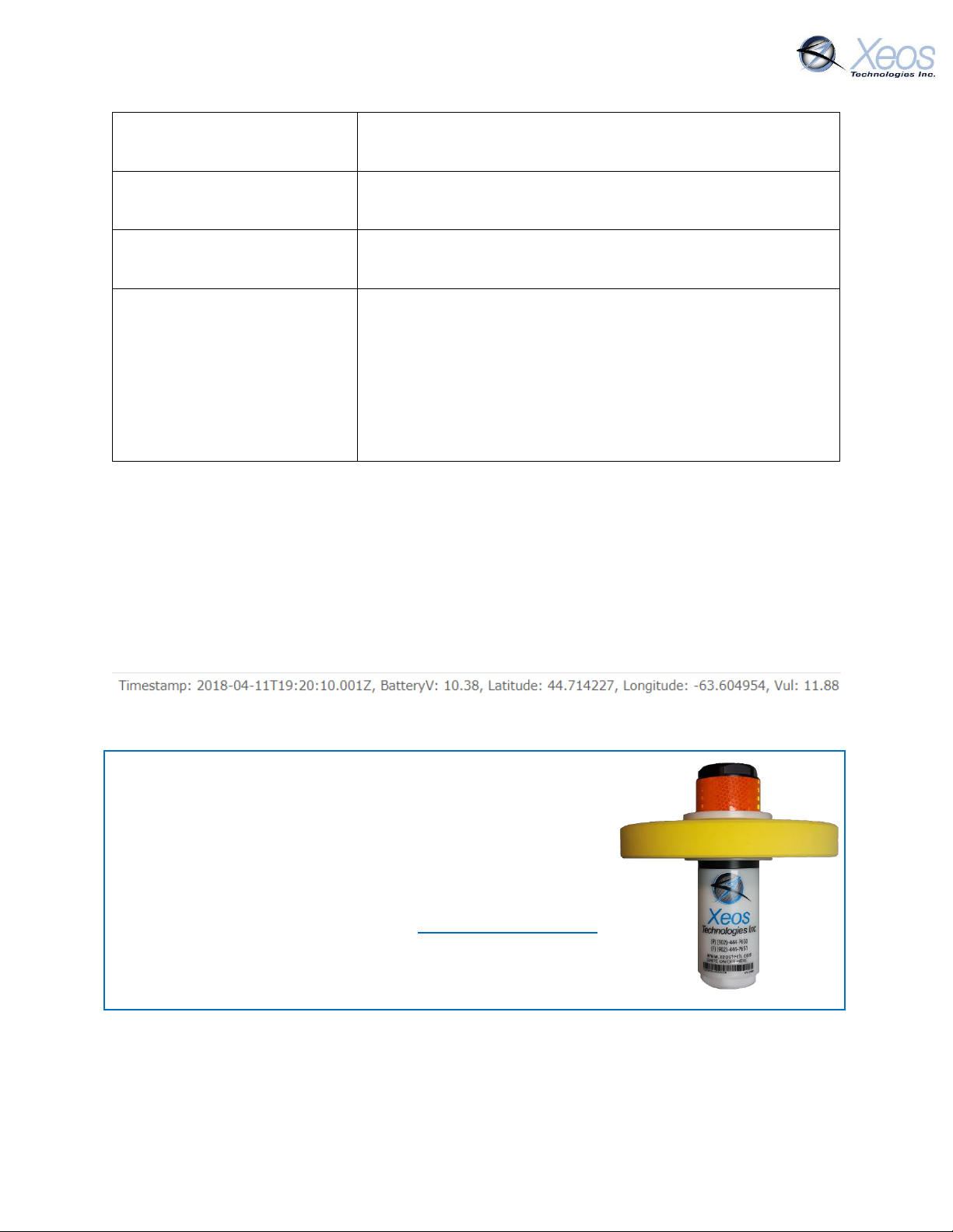
ROBY
The ROBY model is a modified Rover unit, designed for surface
tracking of oil spills. The ROBY incorporates a highly visible
urethane foam float and user-configured watch circle
functionality to keep track of spill movement.
The ROBY functions identically to the Rover except for the
removal of the inverted alarm mode and different timer intervals.
Therefore, the ROBY will transmit consistently from either end
until it has exited its designated Watch Circle area.
Rover User Manual Version 3.0 11
Page 12
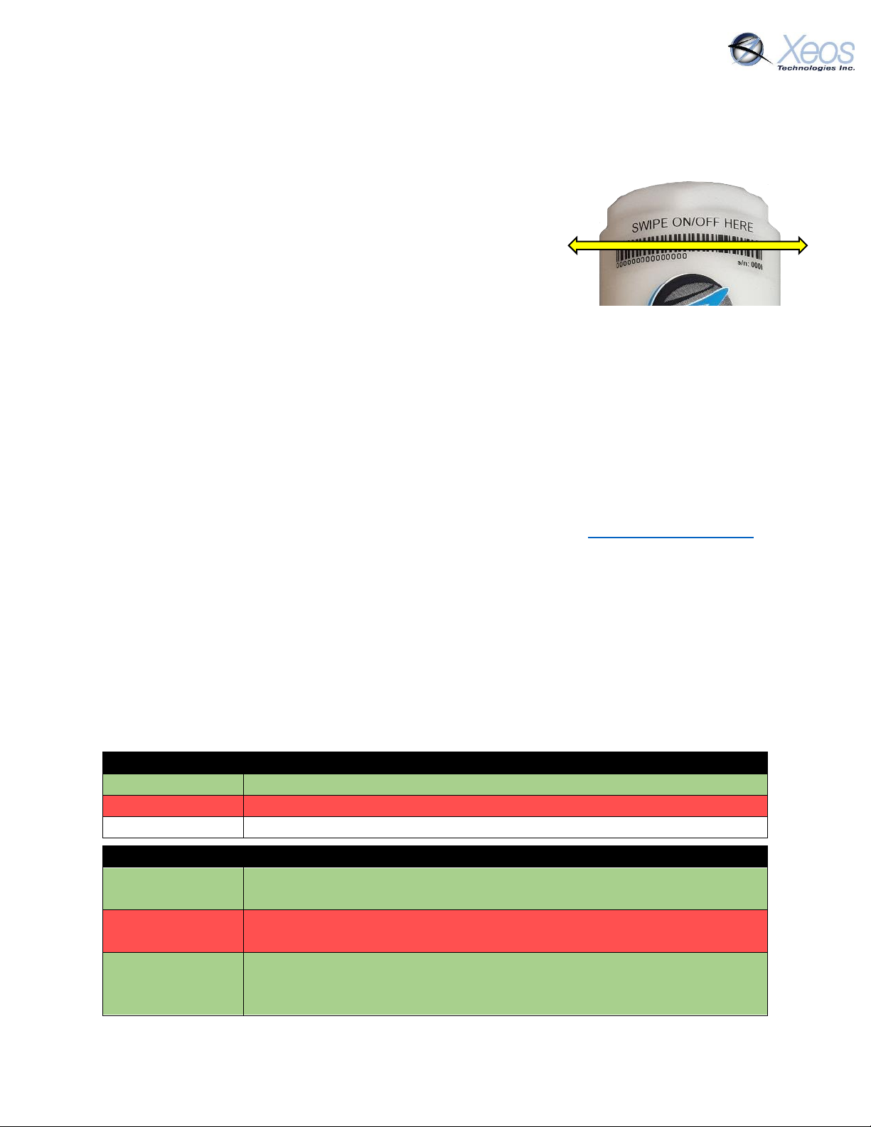
Unit Status Indicators
Action: Turn On
Swipe Magnet back and forth across topside until LED is solid green
Action: Turn Off
Swipe magnet back and forth across topside until LED is solid red
Check Status
Swipe magnet once across topside (red is off, green is on)
Other Indicators
Flashing 4 Hz on
power-up
Device powering up, performing self-test
Flashing 0.5 Hz
after power-up
Self-test failure
Flashing 4 Hz on
Bluetooth
Connection
Device acknowledging Bluetooth is connected
On/Off Modes
Using the Magnet
The Rover beacon is turned ON and OFF using an external magnet
near an internal magnetic reed switch, and operation can be
identified by viewing the LED through the top of the Rover.
To turn the Rover ON, begin swiping the magnet slowly up and
down at the location of the reed switch. The reed switch is located
directly behind the Swipe On/Off Here label.
To turn the Rover OFF, repeat the above procedure with the magnet and watch the LED change
from green to red. A red flashing LED indicates the device is powering down; continue to swipe
the magnet until you see a solid red LED. A solid red LED indicates that the device is turned OFF.
At any time, the magnet can be placed against the location of the reed switch once to see which
mode the beacon is currently in. A red LED indicates the device is turned OFF. A green LED
indicates the device is turned ON.
If the batteries are low, or if some of the batteries have been inserted incorrectly, the Rover will
sound a quick intermittent beep and flash the red LED at the top for 5 minutes, or until the
batteries have been corrected or replaced. If this behavior persists even if the batteries are full
and oriented correctly, this indicates a SELF-TEST FAILURE. Contact [email protected] if
this occurs.
It is important to let all LEDs stop illuminating before initiating another action.
Cycling power for any reason, for example by using the switch to turn OFF/ON or by
removing battery power, will initiate the Startup Mode.
LED Indicators
The top of the Rover (and bottom of ROBY) use red and green LEDs to show their on/off status.
It is also to be used as an indicator for when the magnetic switch is used to turn the device on/off.
This same LEDs are also used during self-test failure or Bluetooth connection.
Rover User Manual Version 3.0 12
Page 13
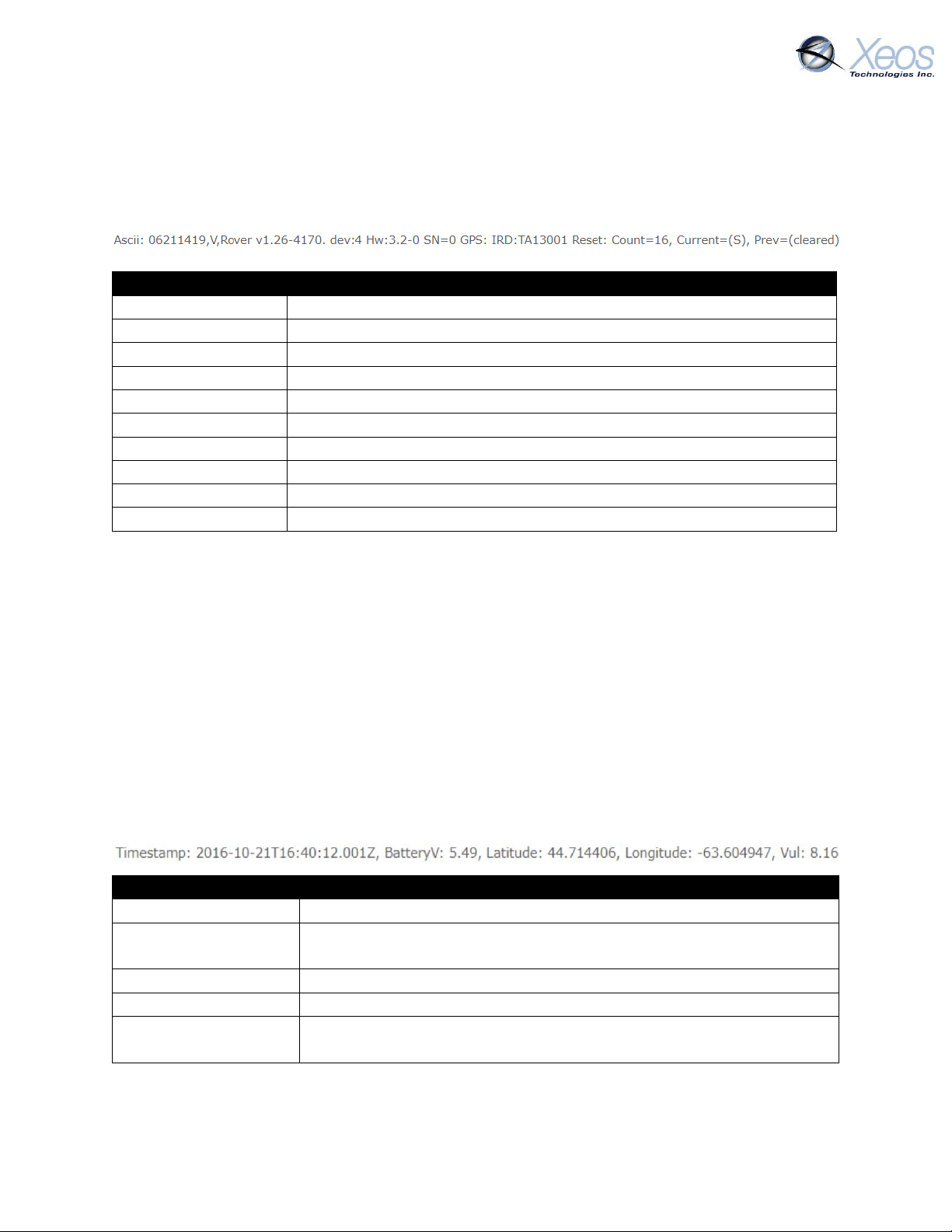
Version Readout
MMDDHHMM
Timestamp in UTC
V
Type of message (Version)
Firmware Version
Product; Major, minor, build of firmware
Hardware Revision
Hardware revision, set during assembly
Serial
The unit’s serial number
GPS Version
Firmware version of GPS chip
Iridium Version
Firmware version of Iridium chip
Reset Count
The number of resets since firmware was uploaded
Current
Cause of last power off
Previous
Cause of previous power off, not used in Rover
Message Log Readout
Timestamp
Date and time in UTC of the latest position reading
BatteryV: 5.49
Loaded voltage of the power supply; minimum battery voltage
observed during the previous Iridium transmission
44.714406
Latitude of fix, decimal degrees
-63.604947
Longitude of fix, decimal degrees
Vul: 8.16
Unloaded voltage of power supply; battery voltage data from
measurement taken just prior to the turning on of the Iridium modem
Messages From the Rover
Version
The $ver command will return a summary of both firmware and hardware versions:
Position Message
Typical position messages are sent in compressed binary format (Message Type 10) to save on
data usage and are parsed in XeosOnline. If XeosOnline is not used, GPS Text Short (Message
Type 0) can be used to read position messages as P-Type.
Compressed Binary Position
The default format for positions is compressed to save on Iridium data usage. This binary format
is parsed into a readable format by XeosOnline, placing its full contents in the Message and
Location Logs. The binary format is stackable and can transmit more than one position per Iridium
transmission. In this situation, all recorded positions will be displayed in the Location Log, while
the latest position will be displayed in the Message Log.
Rover User Manual Version 3.0 13
Page 14
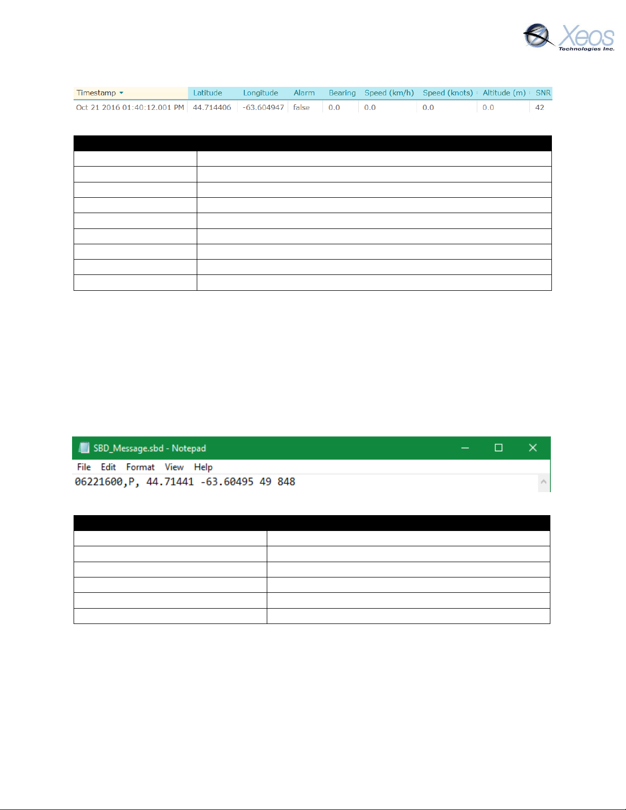
Location Log Readout
Timestamp
Date and time in UTC of this specific position reading
44.714406
Latitude of fix, decimal degrees
-63.604947
Longitude of fix, decimal degrees
Alarm: False
Indicates if the device has determined if it is in an alarm state
Bearing
Direction of movement determined by device
Speed (km/h)
Speed measurement in kilometers per hour
Speed (knots)
Speed measurement in knots
Altitude
Not used
SNR
SNR (Signal-to-noise ratio) of GPS Fix, higher is better (>37 is good)
Position Readout
06221600
Timestamp in UTC (Month/Day/Hour)
P
Type of message (Position)
44.71441
Latitude of fix, decimal degrees
-63.60495
Longitude of fix, decimal degrees
49
SNR (Signal-to-noise ratio) of GPS Fix, higher is better
848
Unloaded voltage of device at the time of GPS Fix
Each compressed message is 26 bytes in size, with an additional 11 bytes added for each
additional “stacked” position.
ASCII Position (Type P)
In ASCII position format, only the most recent fix is sent at each interval, therefore it is most
efficient to have GPS and Iridium intervals equal. This message also appears as it is shown below
in XeosOnline.
P-type messages are approximately 39 bytes:
The message type used can be changed using the $msgenable command.
Rover User Manual Version 3.0 14
Page 15
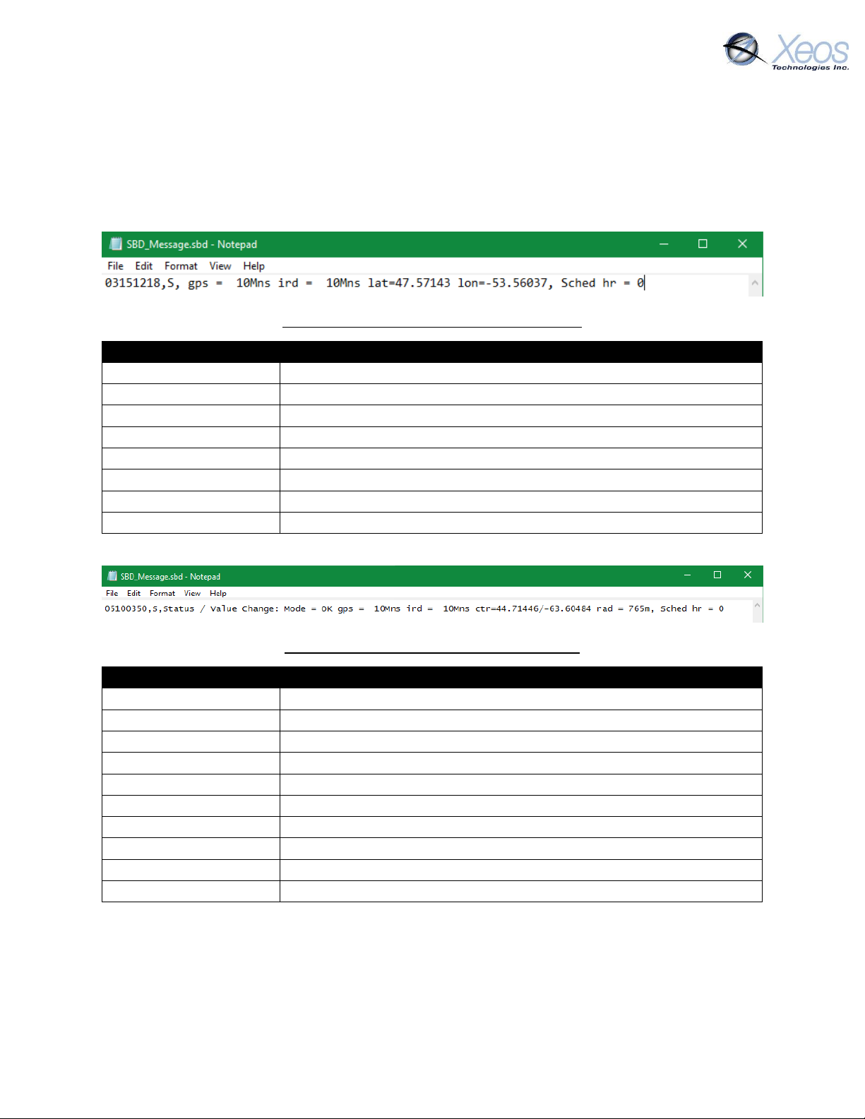
Status Readout – Watch Circle Disabled
03151218
Timestamp in UTC (Month/Day/Hour)
S
Type of message (Status Change)
Status / Value Change
Indicates that a setting has been changed
gps = 10Mns
Currently used GPS repetition rate
ird = 10Mns
Currently used Iridium repetition rate
lat=47.57143
Latitude of latest fix
lon=-53.56037
Longitude of latest fix
Sched hr = 0
Timing offset of Iridium/GPS sessions from UTC, set via $reporthour
Status Readout – Watch Circle Enabled
03151218
Timestamp in UTC (Month/Day/Hour)
S
Type of message (Status Change)
Status / Value Change
Indicates that a setting has been changed
gps = 10Mns
Currently used GPS repetition rate
ird = 10Mns
Currently used Iridium repetition rate
ctr
Indicating the lat/long/radius below are the centre of the circle
lat=47.57143
Latitude of installed watch circle
lon=-53.56037
Longitude of installed watch circle
rad=765m
Radius of the watch circle in meters
Sched hr = 0
Timing offset of Iridium/GPS sessions from UTC, set via $reporthour
Status Change Message (Type S)
Status messages are sent from the device when there has been a change to the operation of the
device, whether a timing change between modes (start-up mode to normal mode, alarm mode
to normal mode) or changes to the watch circle details. If watch circle is not enabled, its
information is omitted. This message is always sent in ASCII format.
S-Type Message with Watch Circle Disabled
S-Type Message with Watch Circle Enabled
Rover User Manual Version 3.0 15
Page 16
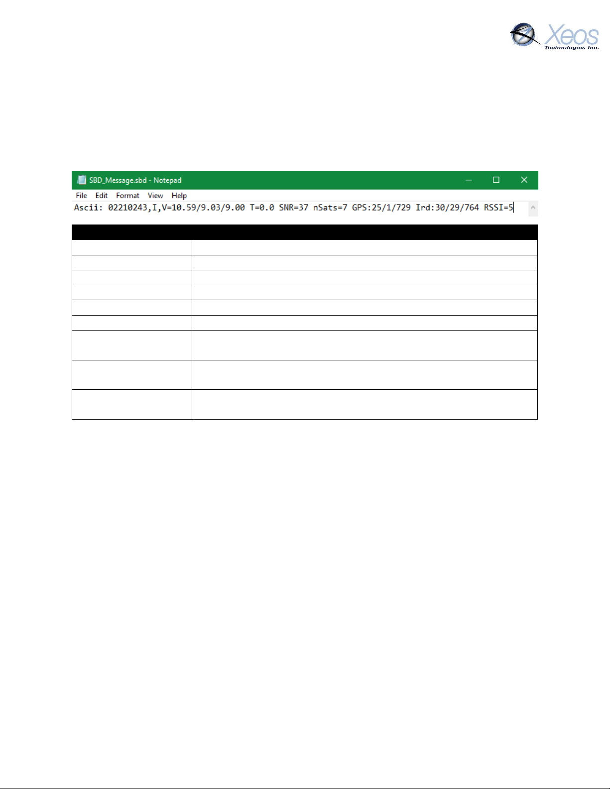
Information Readout
02210243
Timestamp in UTC (Month/Day/Hour)
I
Type of message (Information)
V=10.59/9.03/9.00
Battery voltages unloaded/after Iridium session/after GPS session
T=0.0
Most recent temperature measurement, not used in Rover
SNR=37
MaxSNR (Signal-to-Noise ratio) of the last GPS attempt
nSats=7
Number of connected satellites during last GPS attempt
GPS:25/1/729
Quantity of good fixes since powerup, fails/Quantity of failed fixes/
Seconds total GPS has been powered on since power-up
Ird:30/29/764
Quantity of Iridium messages/Quantity of Iridium sessions/ Seconds
total on time for Iridium
RSSI=5
Value reported back from the modem. Always a number
between zero and five; five being the strongest signal.
Information Message (Type I)
In situations where the device fails a GPS session through low SNR or other factor, the follow-up
Iridium session will send a synopsis of the latest statistics from the device. This message will
always be in ASCII format regardless of message format settings and approximately 80 bytes.
This message can be prompted using $sysinf
Orientation Change Message
The Rover will automatically switch back and forth between the two antenna arrays as the tilt
sensor detects shifts in position.
The tilt axis defaults to the horizontal axis; if the Rover is standing upright, it will operate using
the custom dual antenna at the top of the enclosure. If the Rover crosses the horizontal axis, i.e.
orientated upside down, it will switch to using the dual antenna located at the bottom of the
enclosure.
When the Rover is inverted, it enters Timer 2 and lets the user know it has inverted by sending a
Stats message. The Rover does not recognize it has inverted until the device attempts a GPS
session and requires the use of the antenna opposite of the one it used during the last session.
Each time an orientation change occurs, the device increments the Orientation Change Count at
the top of the Stats message. This occurs both when the device goes inverted, and when it is
restored to an upright position.
The ROBY does not use Timer 2, but will transmit this message on power-up since it is deployed
in the inverted orientation.
Rover User Manual Version 3.0 16
Page 17
Communicating with the Rover
There are 3 ways to communicate with the Rover:
1. Over-the-air with E-mail SBD messages
2. Over-the-air with XeosOnline
3. Locally with Bluetooth
Sending Commands via Email
To receive commands from the Iridium network, the device in use must have a clear view of the
sky. If the device is unable to communicate with the Iridium network, commands will remain
queued for five days.
Command Format
Creating the File
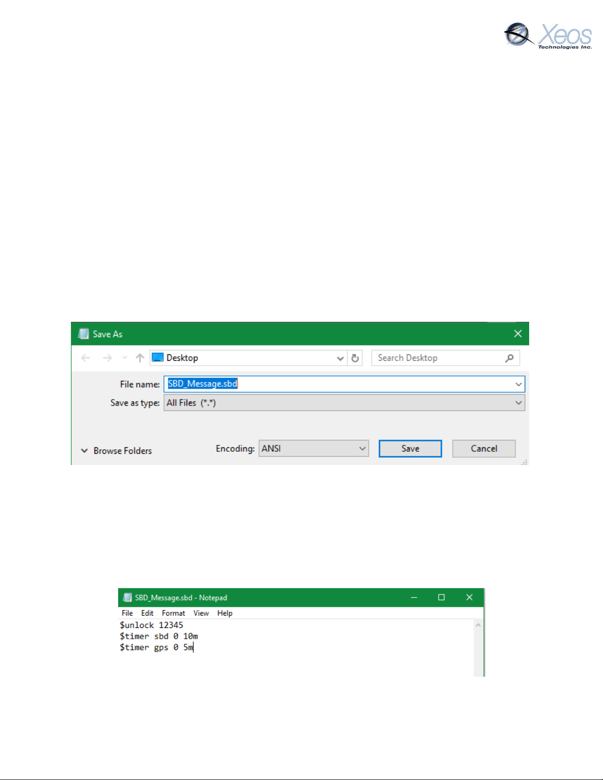
To create an SBD command, open a new file in a text editor (ex. Notepad) and save it using the
.sbd extension. Make sure the Save as type option is set to All Files to achieve this.
Command Structure
Commands must be structured in the following way:
1. Each command MUST have a dollar sign ($) before each command.
2. The unit’s unlock code in the following format: $unlock XXXXX where XXXXX is the
unit’s five digit unlock code.
3. A list of commands, one command per line.
Rover User Manual Version 3.0 17
Page 18
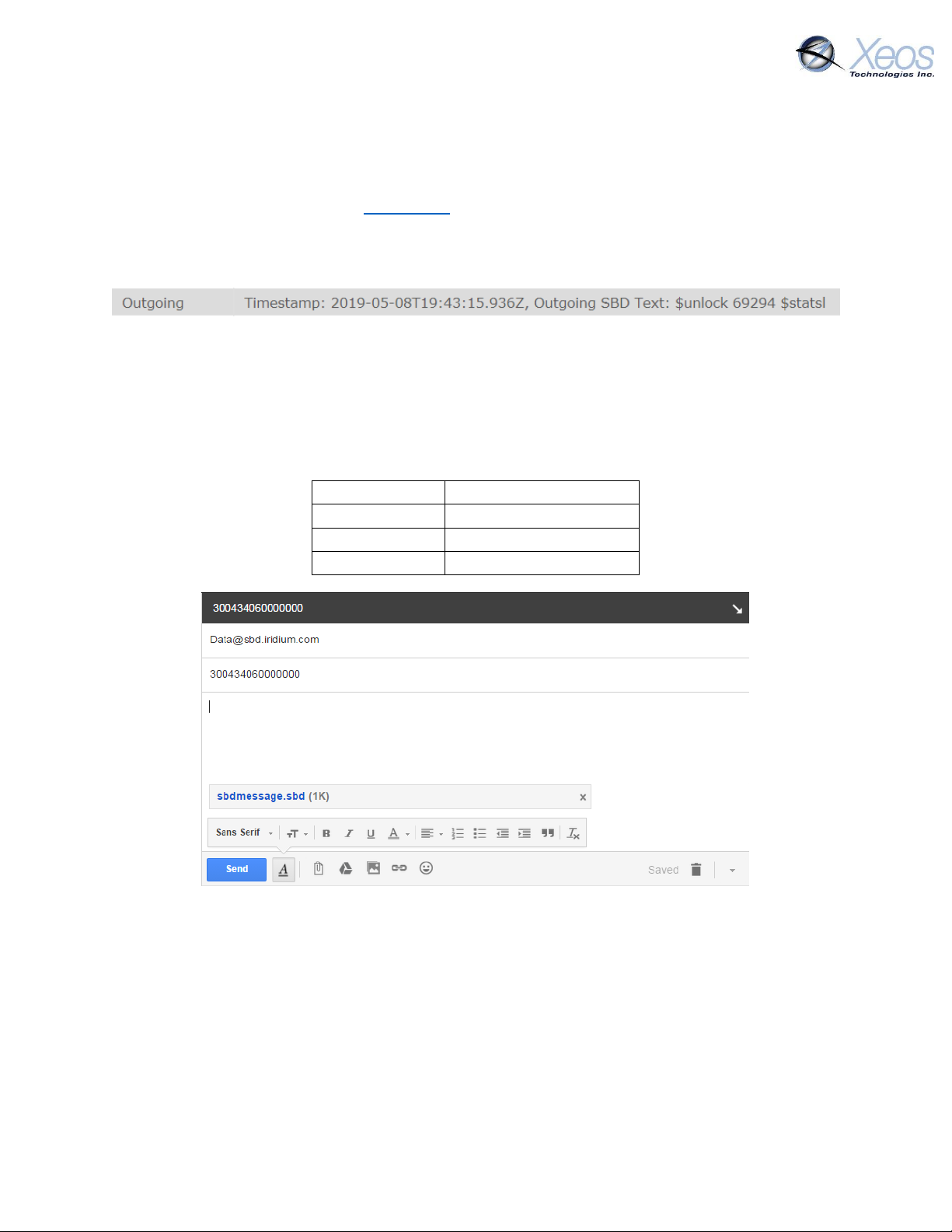
To
Subject
Your device’s IMEI
Body
Empty
Attachments
Your .sbd file
The Unlock Code
SBD commands without an unlock code will be ignored by devices that require it. These devices
include the Apollo, XMI, Onyx, Rover, and OSKER. The unlock code is generated by the device
itself and can be retrieved from XeosOnline, or you can query the unit for the unlock code by
sending $unlock to the device as a command. The device will respond by sharing the 5-digit code
with its provisioned destinations.
Navigate to your unit and click on the Message Log Tab. You will see the unlock code in the
most recent outgoing messages
Sending the Command
To send your sbd command, create a new email message with the following fields:
A confirmation will be immediately returned from the Iridium Gateway from the address
[email protected] indicating that your message is now in the message queue. It will
be delivered to the device during its next Iridium check.
Commands can be sent from any email address, but responses will be returned only to email
addresses on the unit’s forwarding list.
Rover User Manual Version 3.0 18
Page 19
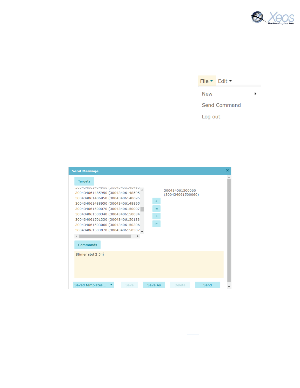
Sending Commands Using XeosOnline
Before using XeosOnline make sure that your account has been set up and your device added to
your organization. Contact [email protected] for more information.
Setting up to Send
Navigate to the Send Command window.
From the Home Tab, choose
File > Send Command
Select the units you wish to target with commands and move them
over to the right-hand target list using the -> button. Type your
command(s) into the command box and press send.
Remember to include the dollar sign ($) ahead of each command, and enter each command on a
separate line.
Outgoing messages will appear in the Message Log for the commanded device.
Xeos Beacon Bluetooth App
Select Xeos products can be configured locally using the Xeos Beacon Android App. This method
of communication requires no disassembly.
The Bluetooth app allows for communication, configuration, logging and firmware updates. A
detailed document on how to use the application can be found here.
Rover User Manual Version 3.0 19
Page 20
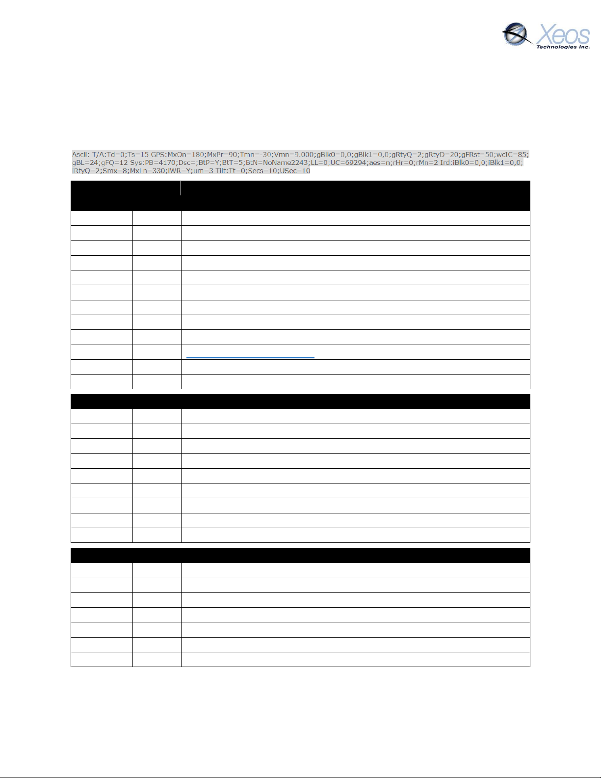
Name
Default
Description
GPS Settings (GPS)
MxOn
180
Maximum GPS session length in seconds
MxPr
90
Maximum GPS session length in poor conditions
Tmn
-30
Temperature minimum
Vmn
9.000
Voltage minimum
gBlk0
0,0
Unused
gBlk1
0,0
Unused
gRtQ
2
GPS retry quantity
gRtyD
20
GPS retry delay in seconds
gFRst
50
Number of GPS failures for GPS reset
wcIC
85
Watch Circle Inner Percent
gBL
24
Maximum saved GPS fixes
gFQ
12
Maximum GPS fixes per message
System Settings (Sys)
PB
Build
Firmware Build
BtP Y Bluetooth on or off
BtT 5 Bluetooth Timeout in minutes
BtN
Name
Bluetooth Name
LL 0 Diagnostic Log detail level
UC
Code
Unlock Code
aes
No
AES Encryption On/Off
rHr
0
Hour on which timings are based (24h UTC)
rMn
2
SBD hour offset in minutes
Iridium Settings (Ird)
iBlk0
0,0
Iridium Blackout, Unused
iBlk1
0,0
Iridium Blackout, Unused
iRtyQ
2
SBD Retry Quantity
Smx
8
Maximum SBD attempts per session
MxLn
330
Maximum message length (bytes)
iWR
Yes
Wait for registration
um 3 Unsolicited messages allowed
Tilt is not used.
Messages to the Rover
Settings
The $settings command will return a truncated list of important Rover settings aside from timers:
Rover User Manual Version 3.0 20
Page 21
Lifetime Statistics Readout
Orientation Change Count
Times Orientation has registered as changed
Timestamp
Time of message
BatteryV
Last measured battery voltage (Loaded, Unloaded)
Uptime
Total unit uptime in minutes
Power Cycle Count
Number of power cycles
Watchdog Reset Count
Number of errors
Lowest Battery Voltage
Lowest measured battery voltage
Highest Battery Voltage
Highest measured battery voltage
Iridium Message Count
The number of SBD messages queued for sending
Iridium Session Count
Total successful Iridium connections
Iridium On Time
Total successful Iridium connections on first try
Iridium Send Failures Non18
Iridium failures, excluding RF drop
Iridium Send Failures Type 18
Iridium failures due to RF drop
Bytes TX
Sum of all data sent in Bytes
Iridium Messages Received
Successfully received SBD messages
Bytes RX
Sum of all data received in Bytes
GPS Sessions
Total GPS attempts
GPS On Time
Total successful GPS fixes on first try
GPS Fix Count
Successful GPS fix count
GPS TTFF Average
Time to first fix, in seconds
High Temperature
Not used with the Rover
Low Temperature
Not used by the Rover
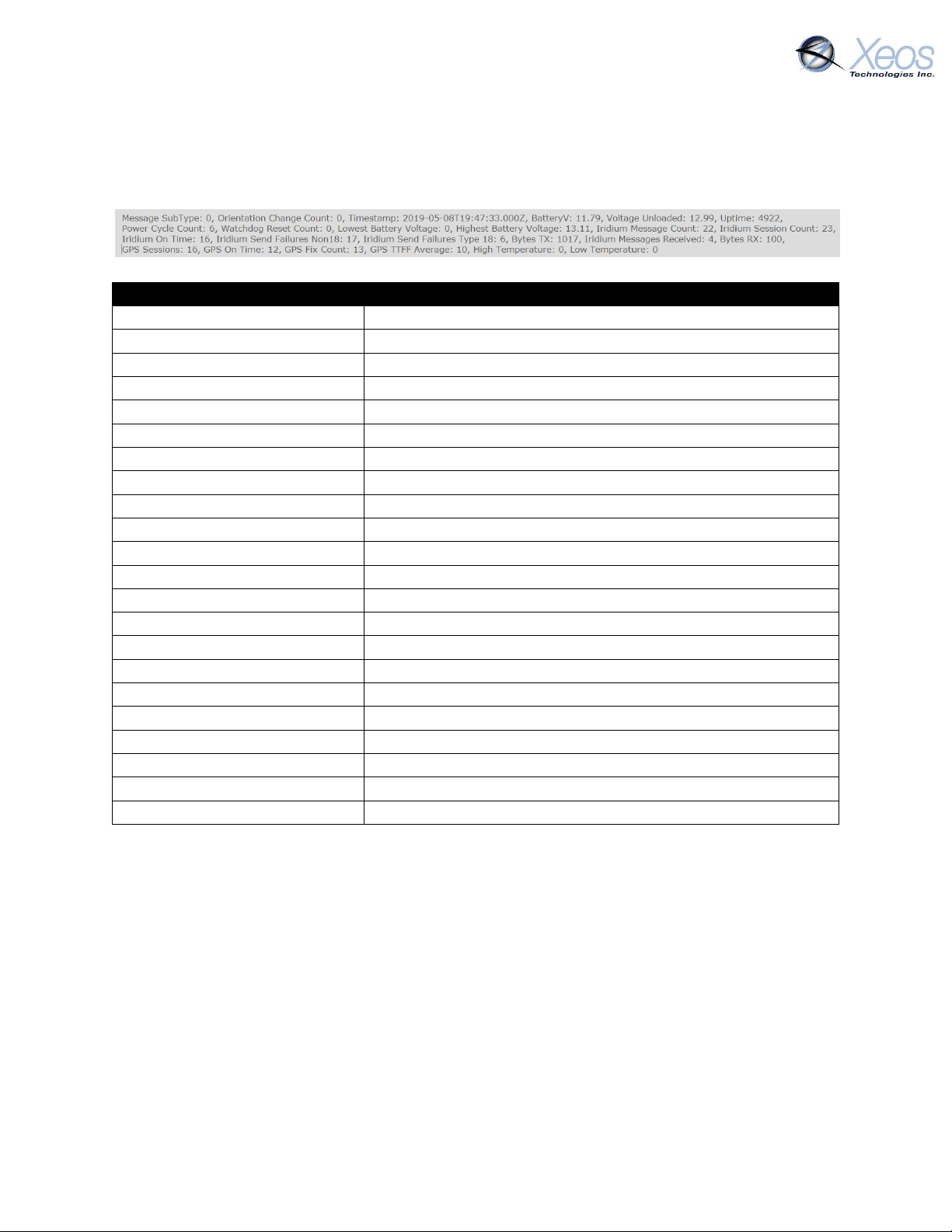
Lifetime Stats
The $statsl command will return various performance statistics recorded since the last firmware
install as well as current statistics:
Stats
The $stats command will return performance statistics recorded since the last power-up. The
stats are like $statsl but exclude Power Cycle Count and Watchdog Reset Count. High and low
battery voltages using $stats will show the values for the last UTC Day.
Rover User Manual Version 3.0 21
Page 22
Timers
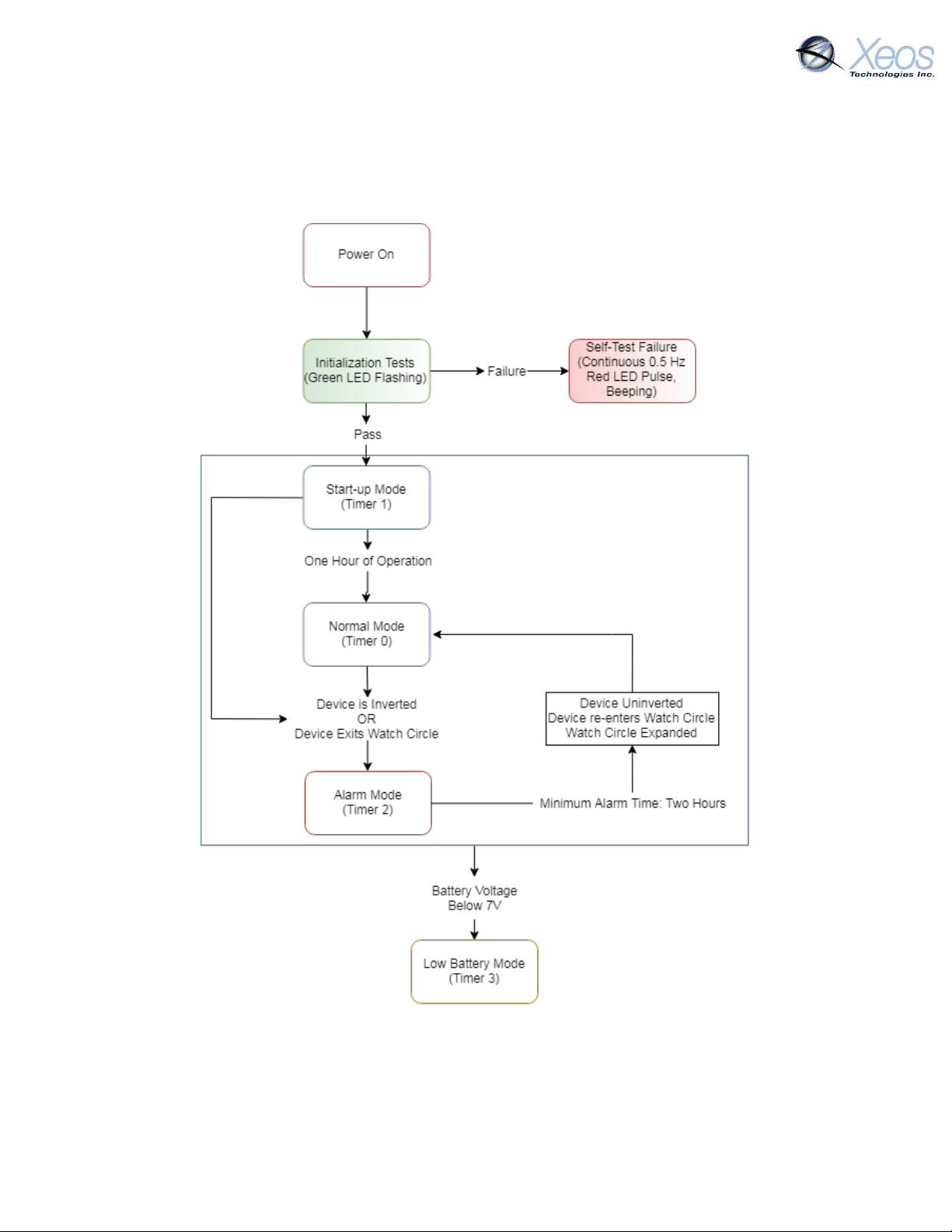
The Rover has a combination of preset behaviors and configurable parameters. Here is an outline
of its normal/default behavior:
Rover User Manual Version 3.0 22
Page 23
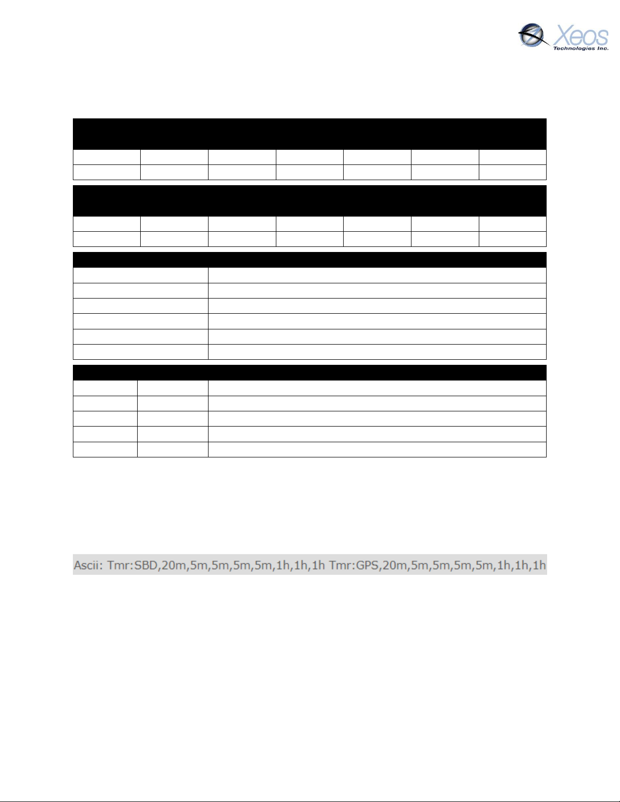
ROVER
Timer
T0
T1
T2
T3
T4
Min-Max
SBD
3h
10m
10m
1d
12h
5m – 1d
GPS
3h
10m
5m
1d
12h
5m – 1d
ROBY
Timer
T0
T1
T2
T3
T4
Min-Max
SBD
10m
10m
10m
1d
12h
5m – 1d
GPS
10m
10m
10m
1d
12h
5m – 1d
Legend
SBD
SBD (Iridium) transmission interval
GPS
GPS acquisition interval
T0 – T7
Timer mode number
#s/m/h/d
Interval in seconds/minutes/hours/days
Min
Minimum allowed interval for this timer
Max
Maximum allowed interval for this timer
Timers
Timer 0
Normal
Used if none of the following modes are triggered
Timer 1
Start-up
Used for the first hour after the unit is powered on
Timer 2
Alarm
Used once the unit is inverted or leaves its watch circle
Timer 3
Low Battery
Used when there is a low battery
Timer 4
No GPS Fix
Used when the GPS module fails to acquire a fix
Rover/ROBY Timer Intervals
The following are the parameters for each mode for the Rover and ROBY.
The default timer settings of the Rover are suitable for most use cases.
Timers 5 - 7 are not used in the Rover.
Timer Command
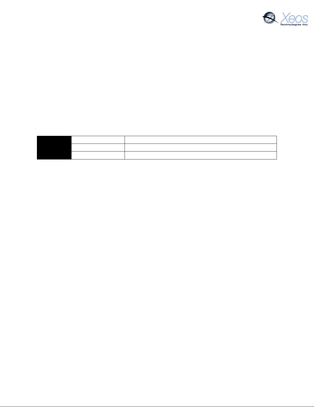
The $timer command will return the timer intervals all configurable settings. The response will
also be returned when timers are changed:
The timer string returned includes a summary of all timers. The first five timers (0 – 4) are used.
Rover User Manual Version 3.0 23
Page 24
Example 1
$timer SBD 2 10m
Changes the SBD interval of Alarm Mode to 10 minutes
Example 2
$timer SBD 0 1d
Changes the SBD interval of Normal Mode to 1 day
Example 3
$timer GPS 0 6h
Changes the GPS interval of Normal Mode to 6 hours
Changing the Timers
Iridium and GPS intervals can be changed to suit the user’s requirements through the use of the
$timer command:
$timer SYSTEM TIMER-MODE INTERVAL
The GPS and Iridium interval timers can be set independently of each other, but there are several
things to keep in mind. The Rover has by default a limit of 12 GPS fixes per Iridium message and
will retain a maximum of 24 unsent fixes (all fixes are saved in internal flash memory). This puts
a practical limit on the ratio of GPS fixes to Iridium checks.
Regardless the method being used to communicate with the Rover, timer commands are always
the same format:
After combining the setup of both Example 2 and Example 3, the user would receive 1 message
every day containing 4 GPS fixes. These messages would be sent at approx. 00:00 UTC.
As with all other settings aside from watch circle centres, all timers are retained through resets
and will be employed at the next power-up.
Rover User Manual Version 3.0 24
Page 25
Note:
If a watch circle is not set by command, but
functionality is enabled, the Rover will average its GPS
location fixes for 48 hours. The device will create a
Watch Circle using the 48-hour average as its centre
and a user-definable radius (default radius is 100m)
Watch Circle
The watch circle functionality allows users to monitor the position of their mooring by receiving
alarm messages when it exits a user-defined circle. This feature aids in the recovery of moorings
that could break free from their planned position.
Recognition of a watch circle exit is tied to the GPS interval of the device in Normal Mode (Timer
0); once a GPS position is logged that shows the device is outside the circle, the device
immediately transitions to Alarm Mode (Timer 2) and transmits according to Alarm Mode timer
intervals.
Enabling the Watch Circle
The watch circle is disabled by default, but can be enabled by the following command:
$WCenable 1
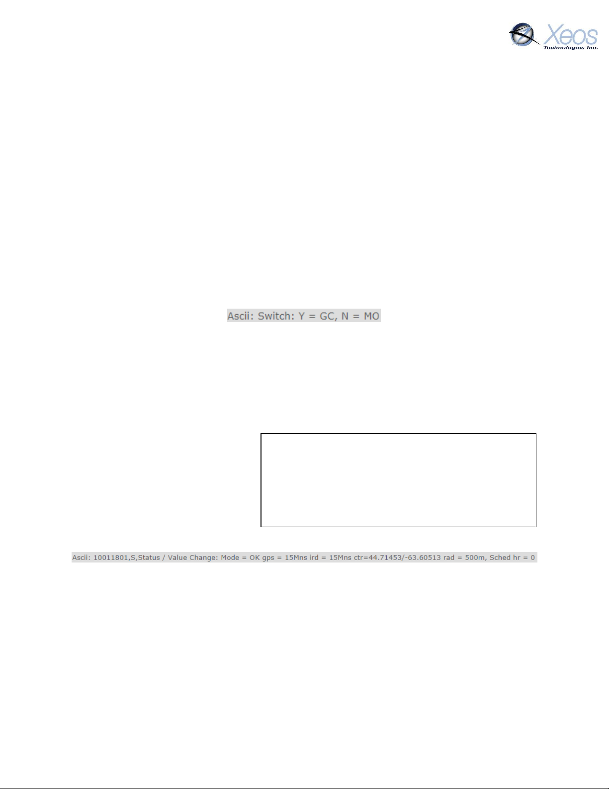
The device will respond with a Switch message in ASCII showing watch circle (component C) is
moved to the Y (yes) column.
Once functionality is enabled, the specifics of the user’s circle can be implemented.
Setting the Watch Circle
The watch circle parameters can be set by sending the $setcircle command using this format:
$setcircle Latitude Longitude Radius
The minimum Radius is 50 meters, while the maximum is 15000 meters.
Example:
$setcircle 47.56989 -53.55682 100
a) $setcircle is the command
b) Latitude is set to 47.56989
c) Longitude is set to -53.55682
d) Radius is set to 100 meters
Upon implementing the watch circle, the Rover will return an S-Type message (see below):
Once the watch circle is set, the unit will operate normally until it approaches the watch circle
radius, at which point the device will send a warning message. Once the device exits the watch
circle radius, it will begin sending alarm messages with GPS coordinates every 10 minutes (Timer
2) until the unit re-enters the watch circle, the radius is expanded via command, or is turned off.
Notes
A maximum of 24 GPS positions can be included in a single SBD transmission. Unlike other
settings, the watch circle’s details are erased at each power up.
Watch circle alert, watch circle warn and inverted mode use the same timer.
You can adjust the Watch Circle’s radius alone by setting the latitude and longitude
Rover User Manual Version 3.0 25
parameters to 0, followed by the new radius.
Page 26
Message Number
Message Type
0
GPS Plain Text Short
1
GPS Plain Text Long
10
GPS Bin Compressed
Timer Mode
Message Types
0
10
1
10
2
10
3
10 4 10
Message Enable
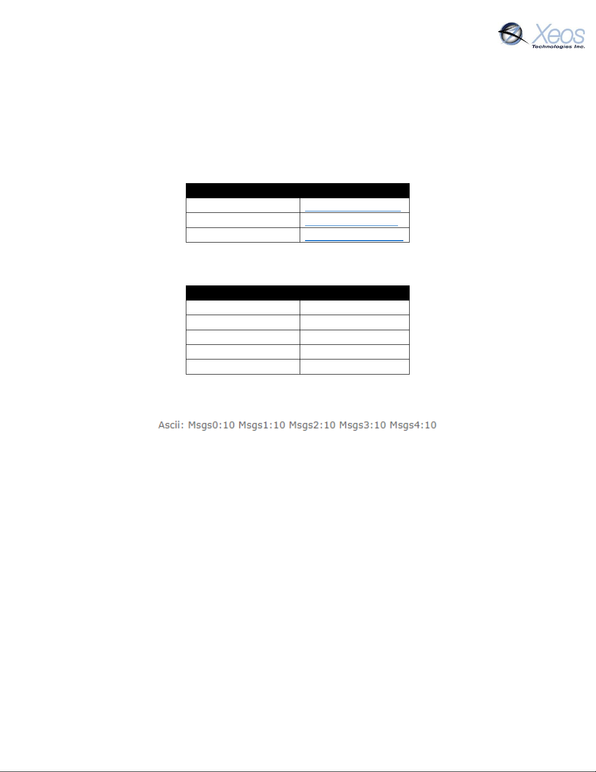
The Rover has several message types that can be enabled for GPS and event messages. At factory
defaults, the Rover will send compressed binary GPS (not human readable) and plain text event
(surface and battery) messages. These message formats can be changed using the $msgenable
command.
The Rover has the following message types available for use:
At factory defaults, the following message types are enabled for each mode:
Sending $msgenable with no follow-up values will return the currently used formats in ASCII:
The $msgenable must be applied to each timer. The message format must be as follows:
$msgenable (timer) (message types separated by commas)
To enable GPS plain text short (Type 0), GPS Text Long (Type 1) and GPS Binary Compressed (Type
10), on Timer 0 (Normal mode) you would send the following command:
$msgenable 0 0,1,10
Any number of message types can be enabled for each timer, but for each additional message
type the Rover will use additional Iridium data.
Rover User Manual Version 3.0 26
Page 27
Baud Rate
57.6k
Parity
None
Data Bits
8
Stop Bits
1
Encryption
The Rover has some security features enabled by default, such as an unlock codes for receiving
commands. As of build 4170, users can also enable end-to-end 256 bit AES encryption between
their device and XeosOnline for an additional layer of security. Messages are zero-padded to fill
out the 32 byte blocks.
Generating your Key
The first step is to provide the Rover with a passphrase over its serial connection.
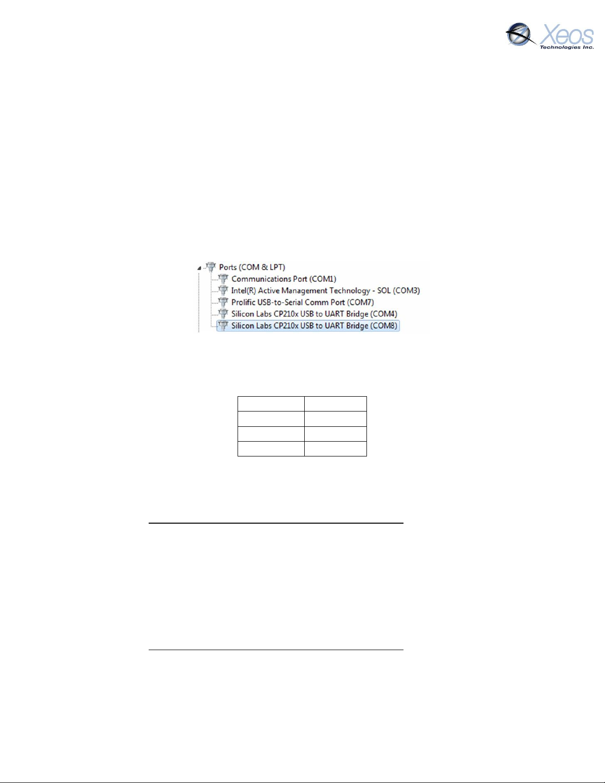
Getting Your COM Port
1. Connect the Rover to the Android app or the internal USB port (requires removal from
enclosure to reach USB port)
2. Take note of the COM port number in Control Panel → Device Manager
In this case: COM8
Connect Using Terminal Emulator
1. Download terminal emulator software
2. Connect to the Rover using the following settings:
3. Enter your encryption passphrase by entering
$aky PASS PHRASE
The pass phrase must be exactly 32 characters long.
Note: This step cannot be done through Iridium.
Connect Using Bluetooth App
4. Download the Xeos Beacon Bluetooth App (Android)
5. Connect to the Rover and navigate to the Terminal Tab
6. Enter your encryption passphrase by entering
$aky PASS PHRASE
The pass phrase must be exactly 32 characters long.
Note: This step cannot be done through Iridium.
Rover User Manual Version 3.0 27
Page 28
Enabling Encryption
1. Using XeosOnline or an SBD email message, send the command $aenbl 1
2. To disable encryption, send the command: $aenbl 0
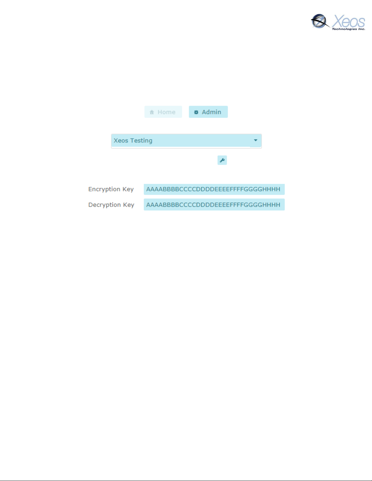
Setting Up Encryption on XeosOnline
1. Log in to XeosOnline and click on the Admin button at the top of the screen.
2. Ensure that your organization is selected in the Organization List
3. Find your device and click the edit device button
4. Enter the Rover’s passphrase into the appropriate text boxes and press Save
Rover User Manual Version 3.0 28
Page 29
Flash Memory
The Rover comes equipped with internal flash memory, used to store logged events and GPS
positions over the lifetime of the product. This information can be retrieved for data collection
or troubleshooting purposes. Since the Rover comes equipped with Bluetooth for configuration
with the Xeos Beacon Android App, this method of communication requires no disassembly.
Refer to the Bluetooth App Guide for more information on the app itself.
Dumping the Flash Memory
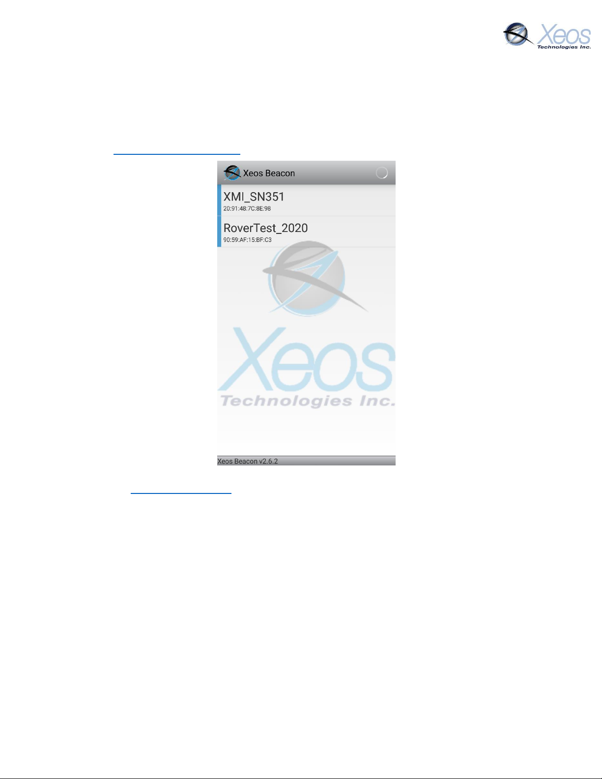
Connect to the Rover using the Bluetooth App for Android. If The device does not
appear as advertising on the main page do one of the following:
Power cycle the device with a magnet or temporary battery removal
Rover User Manual Version 3.0 29
Send the device the following command over Iridium: $btpwr 1
Navigate to the terminal page
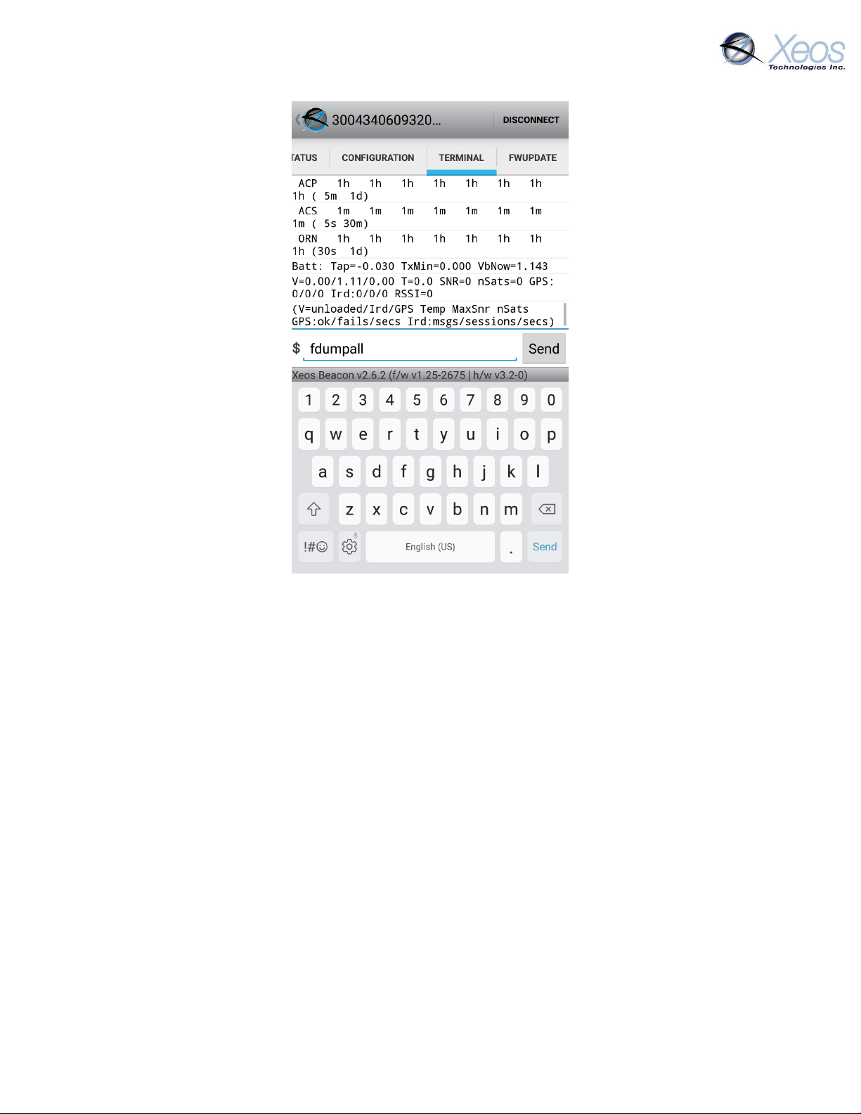
Use the terminal page to send the flash dump command: $fdumpall
The entire memory log of the device will begin outputting into the terminal tab. When
the output slows, the dump is complete.
Output from the Terminal page can be saved to your device in the form of a text file by
tapping the diagnostic output, and tapping Save Output.
The saved file will appear in the Android device’s Downloads directory.
Page 30
Deleting the Flash Memory
The Rover’s memory does not automatically erase. While the Rover can hold several thousand
GPS positions it is prudent to clear the flash memory after extended deployments.
To delete the flash records, send the command: $flasheraseuserdata
The deleting process can take up to 30 seconds, after which the device will reset. Current
settings in the Rover will not be changed by this process.
Erasing of the flash memory can be done over Iridium if necessary.
Rover User Manual Version 3.0 30
Page 31
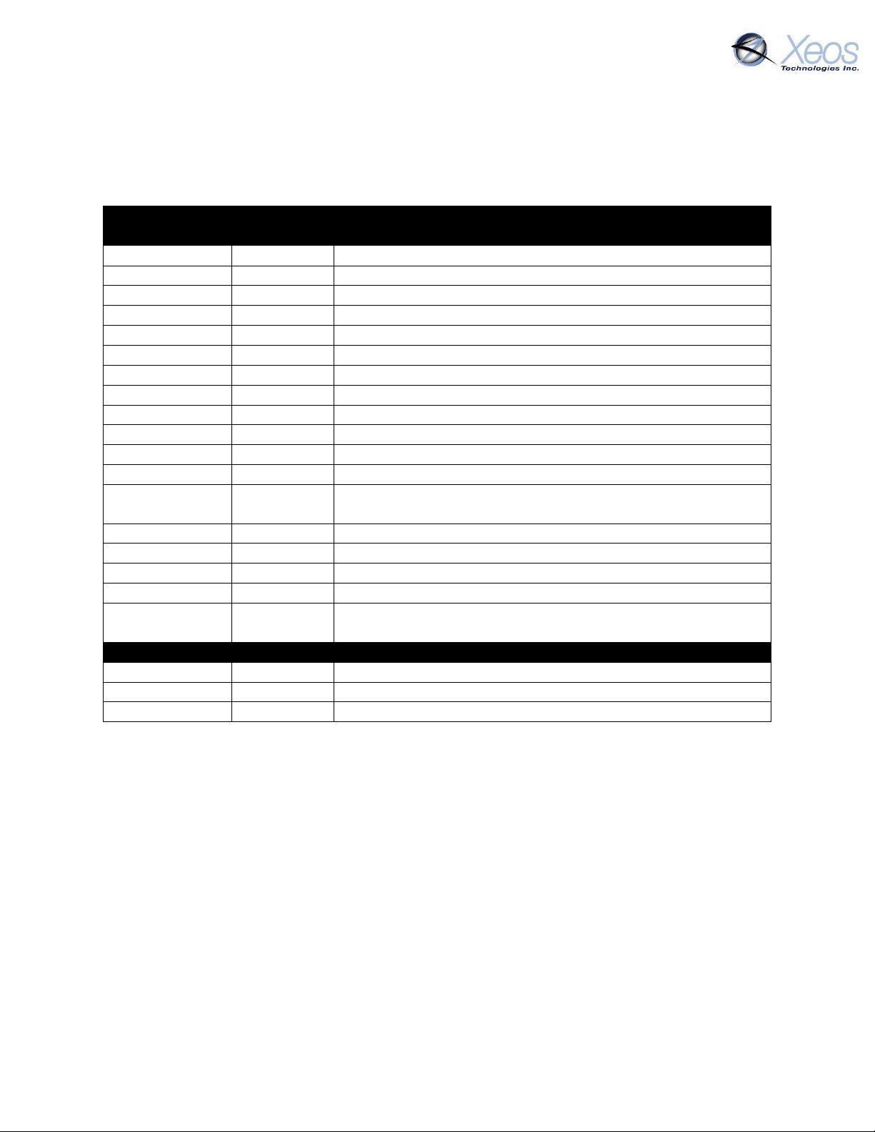
Iridium or Bluetooth
Command
Parameters
Description
ver
---
Show hardware and firmware versions (V-Type message)
Status
---
Show uptime/current timer mode/volts/orientation
startmsg
---
Combination Ver/Timer/Short Settings message
sysInf
---
GPS/Ird summary (I-Type message)
scm
---
Status Change Message (S-Type message)
FactoryDefaults
---
Set all configuration to defaults and reset device
btPwr
1/0
Bluetooth power On/Off
batt
---
Show battery status
settings
---
Show all settings
stats
---
Show statistics (since last powerup/reset)
statsL
---
Show Lifetime Statistics
switch
X 1/0
Switch component X On/Off. No parameter lists components
MsgEnable
timer#
m1,m2,etc
Set & Show which messages are enabled for each Timer
ReportHour
Hour (0 – 23)
Set/Show Daily Reporting Hour offset from UTC
RepMinute
X (Minutes)
Minutes offset past the hour for GPS/Iridium
WCEnable
1/0
Watch Circle Enable/Disable
WCInner
X
Watch Circle percent of radius for elevated GPS monitoring
ResetNow
---
Restarts the system. The effect is the same as restarting via the
magnet
Bluetooth
btpcycle
---
Power cycle Bluetooth
btName
Insert Name
Set Bluetooth name for the Rover, changes after $btpcycle
fdumpall
---
Print out Flash Memory of the Rover (Bluetooth Only)
Other Commands
Below is a list of other commands that can be sent via Iridium or Bluetooth to acquire additional
information, or configure the Rover. Remember to add the $ symbol ahead of any commands.
Rover User Manual Version 3.0 31
Page 32
Testing the Rover
Before testing
The following should be confirmed ahead of testing:
1) The Rover should be confirmed activated on the Iridium network to ensure that any
messages transmitted are able to be received, and directed to send messages to the
intended destinations.
2) Each battery used during the test should be examined with a voltmeter to ensure none of
the cells are defective or discharged. Individual cells with a voltage measuring less than
1.5 V should not be used, but new batteries should be used during deployments.
3) Xeos recommends the Energizer EN91 AA alkaline battery, or the Energizer L91 lithium
Battery. Duracell batteries should not be used as they are prone to leaking under some
conditions.
Testing
Power-up and Batteries
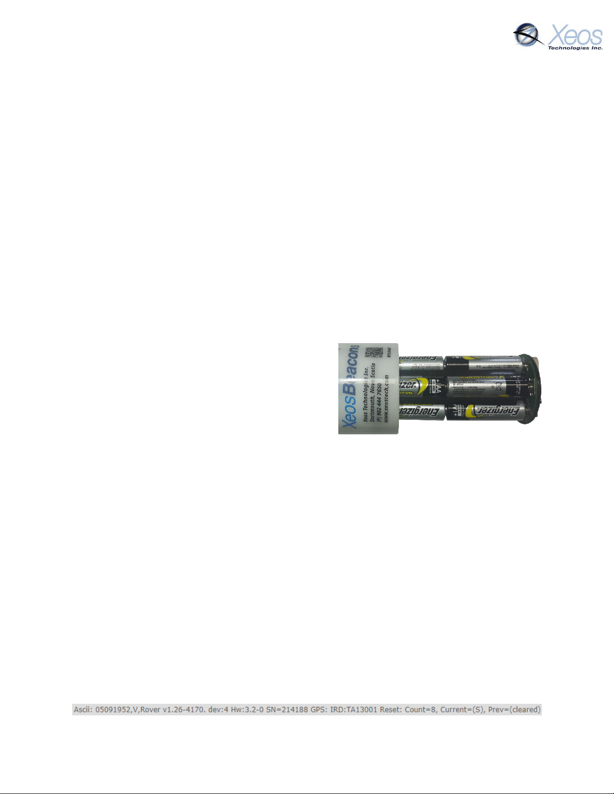
1) Insert the batteries into the device in the
proper orientation. Labels on the battery core
indicate the direction to add the cells.
2) As the last batteries are added, the Rover will
turn on automatically.
If there are still cells missing during
the battery self-test, the Rover will
beep and flash its red LED. This should cease when all batteries are added, so long
as they are of good health.
If the red LED continuously flashes, and/or beeping is heard when all batteries are
added, a self-test failure has occurred. Recheck the batteries and their orientation
first, and if this persists, contact Xeos.
3) Once all LED action has ceased, use a magnet to find the magnetic on/off switch on the
device (the green LED will illuminate on detection). Use this opportunity to turn the device
off by swiping the magnet repeatedly at this location (OFF is indicated by a solid RED LED)
to confirm proper operation of the magnetic switch. Use the same method to turn the
device on (ON is indicated by a solid GREEN LED).
Transmission
1) Place the device upright in a location outside that has as much of the sky visible as
possible; buildings and other tall objects can impede a beacon’s ability to transmit.
2) The following messages are to be expected from the Rover after turning on within five
minutes:
a. A power-up message displaying the firmware version and serial number:
Rover User Manual Version 3.0 32
Page 33
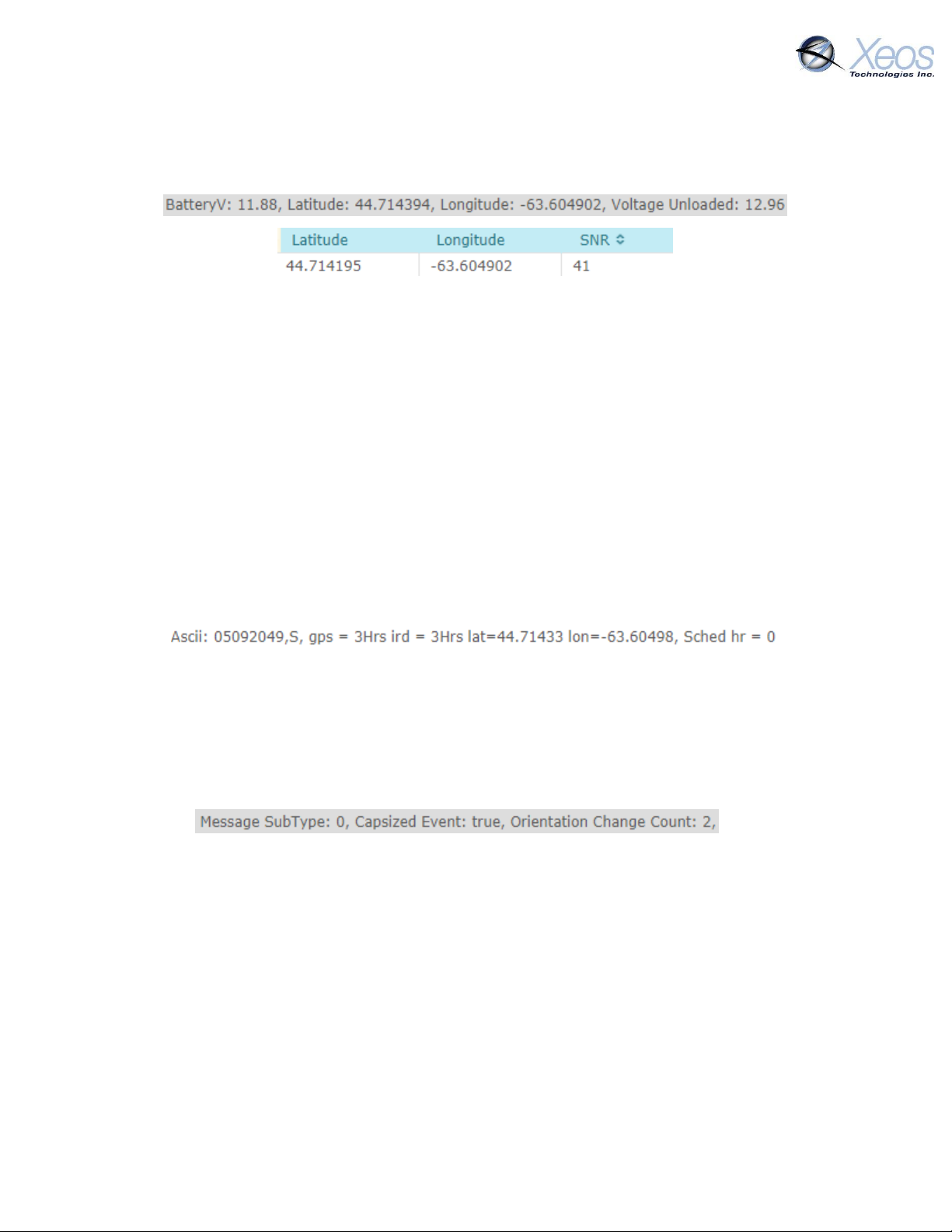
b. A GPS Position, the SNR strength of which should consistently be greater than or
equal to 40. The Position will appear in both the message and location logs, and
the SNR will appear in the location log only.
The device will then send one GPS message every 10 minutes until its start-up period has expired
(a period of one hour). The SNR value for each GPS position should be a value no less than 38.
After this point, transmission intervals are tied to the rates laid out by Timer Zero if upright, or
Timer Two if inverted.
Response to commands
During testing, commands can be sent to the device to change configuration or request statistics.
These commands are read in during Iridium sessions and prompt responses from the Rover,
confirming that said commands were acted upon.
1) Send the $scm command, which will prompt the Rover to report its current timer intervals
and last GPS fix. This message also is automatically sent when one Timer Mode takes over
for another (example: Start-up to Normal Mode after 1 hour of operation).
Response to $scm
Inverted Messaging
At any time while the device is on, invert the device to sit it on its top white section. On the next
GPS session, the Rover will begin utilizing its bottom antenna for GPS and Iridium sessions.
The Rover will send an Orientation Change Message (a variant of the Stats message) on the first
Iridium session after inversion. The beginning of this message is below:
etc…
The Rover should be left in this orientation to allow the Rover to send several GPS fixes with its
bottom antenna. The same expectations in quality should be expected from the bottom antenna
as with the top. If the Rover has been on for greater than one hour, inversion will trigger Timer
2.
Rover User Manual Version 3.0 33
Page 34
Example
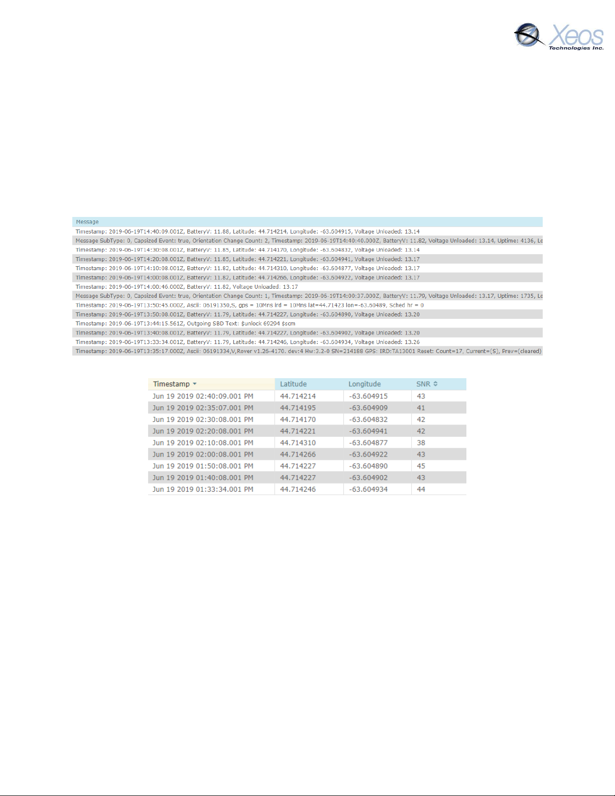
Below is XeosOnline output from a Rover that utilized its default timers and transmitted
appropriately. During the first hour of testing, the $scm command was sent, after which the
device was inverted. After inversion an Orientation Change message was sent on the next
transmission interval.
All GPS SNRs from the top and bottom of the Rover were at or above 38 as expected for successful
test in the Location Log.
Message Log
Location Log
Deployment of the Rover
Below are installation tips for the Rover:
Ensure that the Rover is moored with the white end of the enclosure facing up.
The top of the Rover must have as good a view of the full sky as possible.
o Alongside a wall or tall obstruction will cause coverage to suffer.
o For concealed deployment, the antenna surface must not be obstructed by metal
or wood. Thick amounts of other materials may also cause interference.
Rover should not be deployed near (less than 1 metre) other transmitters.
Rover User Manual Version 3.0 34
Page 35
Maintenance
Batteries
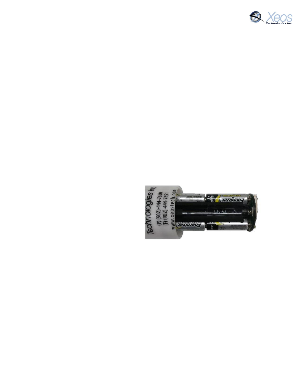
The internal battery pack in the Rover holds 18 AA batteries. There is no provision for external
power.
Choosing Batteries
While the battery pack can hold and operate with any AA battery, some battery models might
experience failure and are not recommended for use. Duracell batteries should not be used since
the seal is more apt to fail and cause leakage in higher temperature conditions.
1. Xeos recommends the Energizer EN91 AA alkaline battery, or the Energizer L91 Lithium
battery. Do not mix battery types.
2. All new batteries should be used for each new deployment.
3. Each battery should be tested with a battery tester or voltmeter to ensure none of the
cells are defective or discharged. Individual cells with a voltage measuring less than 1.5 V
should be discarded.
When not in use, the Rover should not have batteries installed.
Adding/Replacing Batteries
The batteries are configured in 6 columns of
3 batteries each.
Each column is labelled to show the correct
orientation the batteries should be installed.
Take care to orient the batteries the correct
way as the columns alternate direction.
Incorrect battery installation will activate
the self-test failure mechanism.
The battery pack column is magnetized to ensure the batteries stay in place properly.
To add/replace batteries:
Open the housing
Remove old batteries by pulling the bottom batteries from the springs, and sliding the
rest down with a single shake.
Slide the new batteries into each column with respect to its labelling for correct
orientation
The Rover may beep to indicate changes in the battery voltage as it can start as final batteries
are installed.
Once all the batteries have been replaced, the Rover will stop beeping. The enclosure pieces can
be reassembled, taking care to inspect and seat the O-Rings first.
Rover User Manual Version 3.0 35
Page 36
O-Rings
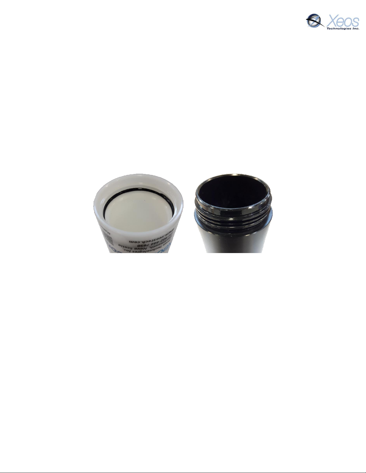
O-rings are critical to the waterproof nature of the Rover. O-rings should be visually inspected to
make sure they are properly seated in the groove and to ensure there is no visible damage to the
O-ring.
If the O-rings pass visual inspection and have been deployed for 2 months or less, the O-rings do
not need to be replaced.
If the O-rings fail visual inspection or have been deployed for longer than 2 months, the O-rings
should be replaced prior to re-deploying the Rover.
Inside the Rover’s acetyl housing, there are two (2) O-rings:
1) 568-138 90D DURO BUNA (Top, White Section)
2) 568-137 90D DURO BUNA (Bottom, Black Section)
To replace an O-Ring:
Remove the old O-ring using a soft tool (toothpick) to avoid scratching the o-ring groove.
Clean all dirt away from the threads and grooves where the old O-ring was seated using
a lint-free cloth, cleaning alcohol, and a soft brush.
Apply a thin layer of O-ring lubricant (Molykote 111 from Dow Corning) to the new O-ring
o For the outer ring, gently slide the new O-Ring down over the threads of the black
section of enclosure and into the O-ring groove, above the lip of the enclosure.
o For the inner ring, gently slide the new O-Ring down inside the white section of
enclosure until it is seated in the O-Ring groove.
Note: It is very important to be aware of where the O-ring is sitting in the two O-Ring locations.
If the O-ring is not sitting perfectly in its groove, there will not be a perfect seal and could cause
fatal damage to the unit.
Rover User Manual Version 3.0 36
Page 37
Removing the ROBY float
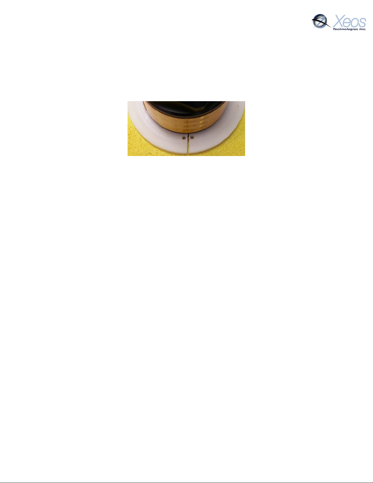
Xeos does not recommend removing the ROBY’s float unless it is necessary. The unit can be used
and disassembled while the float remains on.
1. Using a pair of internal snap ring pliers, stretch the top ABS brace until it can be slid off
the ROBY’s top cylinder.
2. Repeat step one for the bottom brace.
3. After both braces have been removed, the float can be slid off the ROBY.
Recovery and Storage
Once, the Rover is recovered, it is important that it be stored and maintained properly for future
deployments.
As soon as possible after the Rover is recovered, all batteries should be removed and discarded.
The Rover should be cleaned and inspected for corrosion or water ingress. O-rings should be
visually inspected. Any concerns should be discussed with Xeos support (+1-902-444-7650 or
[email protected]) prior to storage.
The Rover should be stored as follows:
Dry location
Assembled, without batteries but with O-rings in place
Ambient temperature of -40° C to +85° C
Either horizontal or vertical storage is permitted
Rover User Manual Version 3.0 37
Page 38

Source:
Repair or replacement must be done by Xeos Technologies Inc.
1-902-444-7650 or [email protected]
Only use new, approved batteries for deployments. In the event used
batteries are for short term testing, batteries must have equivalent
battery voltages to prevent reverse charge forming and subsequent
battery leakage.
Visual inspection of the battery compartment should be done after
each deployment to ensure there has been no leakage. Signs of
corrosion, leakage or water ingress should be reported to Xeos
immediately.
Part Number:
568-138 90D DURO BUNA (White Section)
568-137 90D DURO BUNA (Black Section)
Source:
O-rings may be purchased through Xeos Technologies Inc. or from a
variety of vendors. Please call for assistance if required.
Maintenance:
O-rings should be visually inspected prior to each deployment, no
matter how short. Any evidence of wear or stretching requires that
they be replaced.
O-rings should always be replaced after a deployment of 2 months or
more. O-rings should also be replaced after a series of short
deployments adding up to 2 months.
Part Number:
Molykote 111
Source:
Lubrication may be purchased through Xeos Technologies Inc. or
from a variety of vendors. Please call for assistance if required
Maintenance:
Lubrication should be used each time the O-Ring is removed and
reseated
Procedure:
Squeeze a thin layer of lube onto the O-Ring. Gently spread the lube
around the O-Ring until it is completely coated. Follow instructions
for seating the O-Ring
Appendix A: Part Sourcing Summary
Battery Compartment
O-Rings
Seal Lubrication
Rover User Manual Version 3.0 38
Page 39

Source:
Firmware updates are published to the Xeos Beacon Bluetooth App.
For backup USB, firmware is on the Xeos Firmware Repository.
Validated users may log in and download the most up to date
version as needed
Maintenance:
Prior to each deployment, the firmware version should be checked,
and updates applied, if needed. Email [email protected] if
you need assistance determining if you should apply a firmware
update.
Firmware updates can be uploaded via Bluetooth.
Alternative method using Micro-USB on device (requires
disassembly)
Procedure:
A detailed instruction and procedure will accompany each firmware
release.
NOTE: It is very important to be aware of where the O-ring is sitting in the two O-Ring locations.
If the O-ring is not sitting perfectly in its groove, there will not be a perfect seal and could cause
fatal damage to the unit.
Firmware Updates
Rover User Manual Version 3.0 39
Page 40
Mechanical
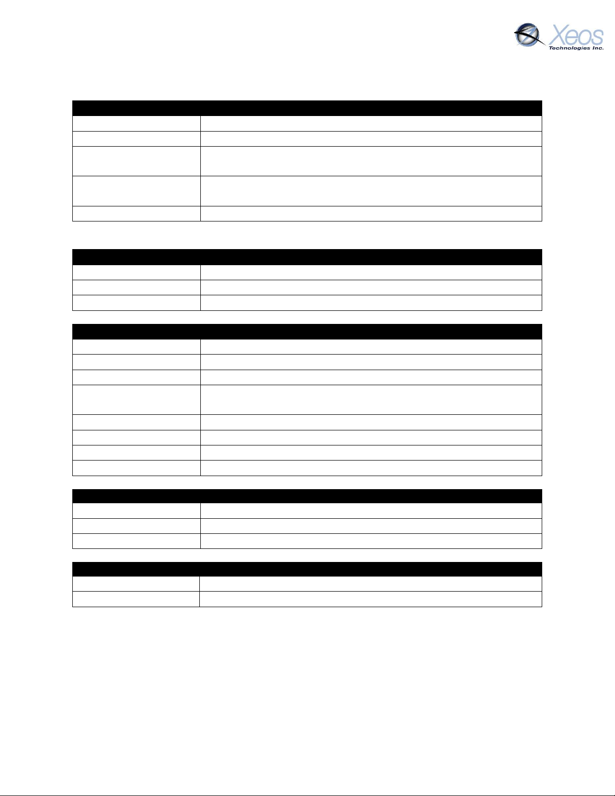
Material
Polyoxymethylene (Delrin)
Dimensions
21.41 cm L x 6.35 cm D (8.43” L x 2.5” D)
Mass (Alkaline)
1055g Out of Water
378g In Water
O-rings
568-138 90D DURO BUNA (Top, White Section)
568-137 90D DURO BUNA (Bottom, Black Section)
Seal Lubrication
Molykote 111
Electronics
Digital Controller
Xeos IRDC-3
GPS Receiver
48 Channel SiRFstarIV, GSD4e GPS chip
Iridium Hardware
9603 Modem
Electrical
Battery Compliment
18 AA batteries (Lithium or alkaline)
Operating Voltage
9 – 32V
Nominal Voltage
13.5V
Battery Capacity
3.0 Amp Hours (alkaline)
5.8 Amp Hours (Lithium)
Iridium Transmission
70mA
GPS Acquisition
13mA
Idle Current
100uA
Off Current
15uA
Electronics
Digital Controller
Xeos IRDC-3
GPS Receiver
48 Channel SiRFstarIV, GSD4e GPS chip
Iridium Hardware
9603 Modem
Environmental
Operating Temperature
-40° C to +60° C (-40° F to 140° F)
Storage Temperature
-40° C to +85° C (-40° F to +185° F)
Appendix B: Technical Specifications
*Specifications subject to change without notice.
Rover User Manual Version 3.0 40
Page 41
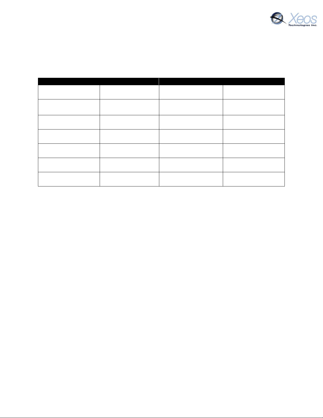
GPS Interval
Iridium Interval
EN91 Alkaline
L91 Lithium
10 min
10 min
38 days
1.24 mths
47 days
1.54 mths
30 min
30 min
110 days
3.61 mths
136 days
4.47 mths
1 hour
1 hour
207 days
6.8 mths
255 days
8.38 mths
3 hours (default)
3 hours (default)
498 days
1 year, 4.3 mths
612 days
1 year, 8.12 mths
6 hours
6 hours
767 days
2 years, 1.21 mths
942 days
2 years, 6.96 mths
12 hours
12 hours
1049 days
2 years 10.48 mths
1289 days
3 years, 6.37 mths
1 day
1 day
1287 days
3 years, 6.31 mths
1580 days
4 years, 3.94 mths
Appendix C: Sample Power Consumption Patterns
Note: These are calculated lifespans and not testing results; environmental factors including
temperature will affect these calculations.
Calculations subject to change without notice. Xeos conducts ongoing battery life and power
consumption tests to provide more accurate information to customers.
Rover User Manual Version 3.0 41
Page 42
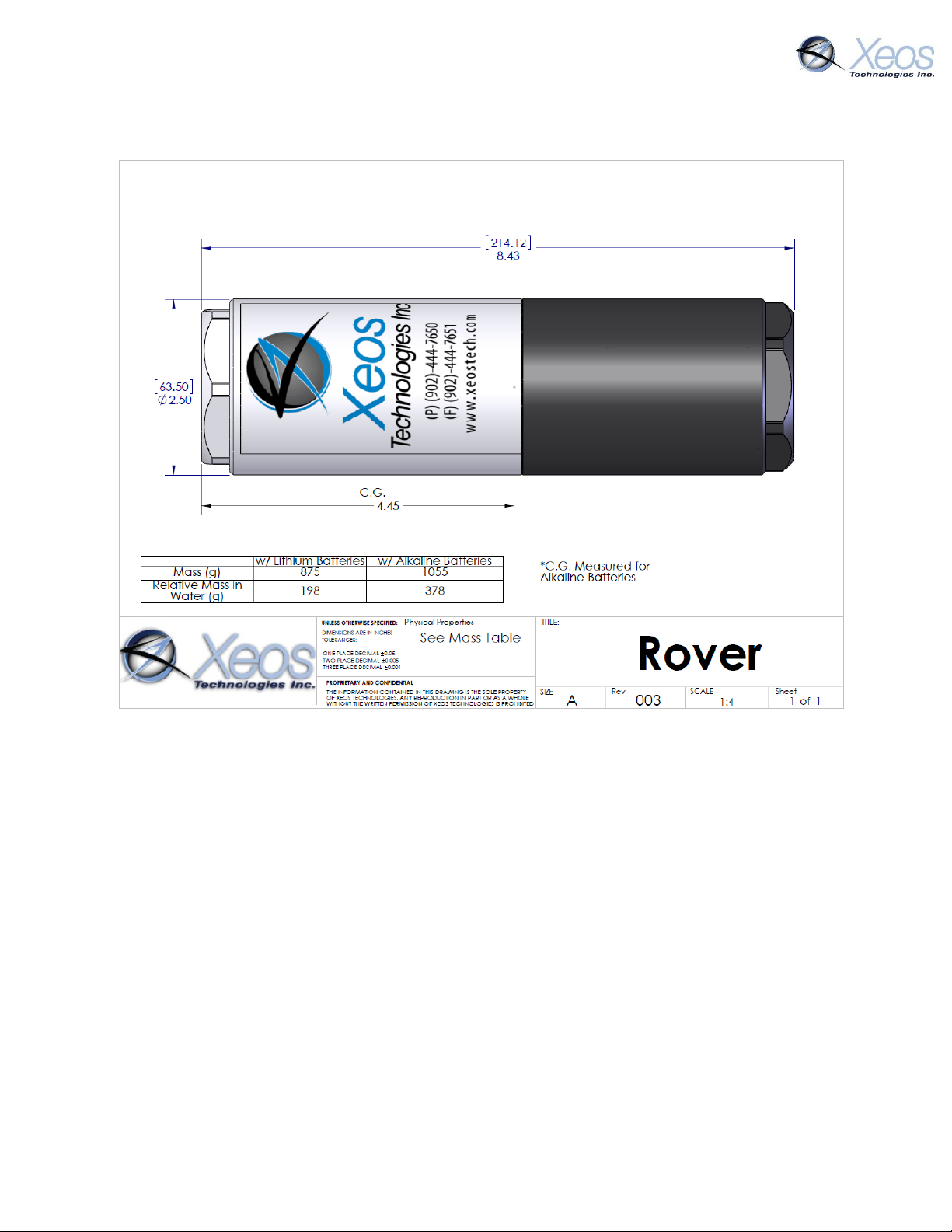
Appendix D: Engineering Diagram
Rover User Manual Version 3.0 42
Page 43
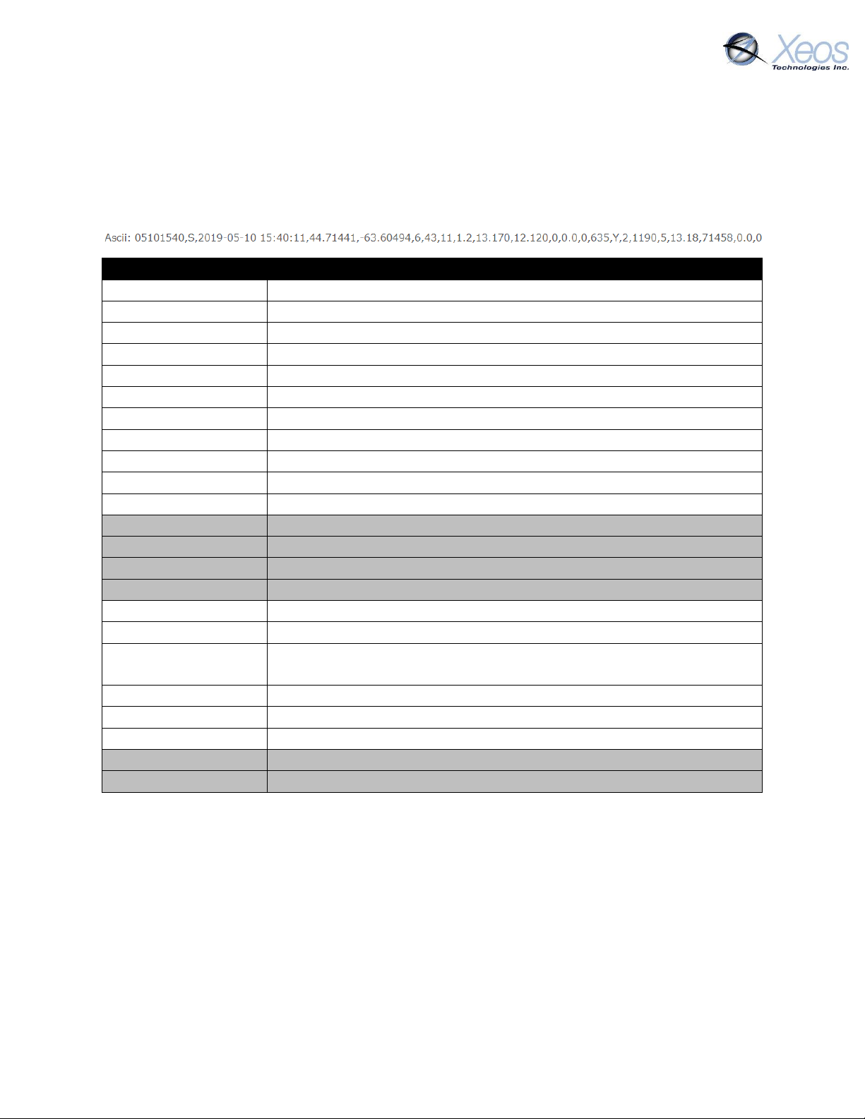
GPS Text Long Readout
05101540
Date and time, MMDDHHmm
S
Status type message
2019-05-10 15:40:11
Date and time, adds year and second of fix
44.71441
Latitude
-63.60494
Longitude
6
Number of satellites seen
43
Maximum SNR of fix
11
Time to fix
1.2
HDOP (Horizontal Dilution of Precision)
13.170
Loaded Voltage
12.120
Unloaded Voltage
0
Temperature
0.0
Speed
0
Heading
635
GPS Horizontal Error
Y
Watch circle set, Yes/No
2
Distance device is from centre of set circle (meters)
1190
Number of seconds device has been in this mode (In-circle or out of
circle, whatever the status is at this time)
5
RSSI (Iridium signal strength)
13018
Battery Voltage
71458
On-second, seconds since power-up/last reset
0.0
Temperature, Degrees C
0
Movement Counter
Appendix E: GPS Text Long
GPS Text Long (Type 1) messages allow for greater detail in ASCII format. These messages are
approximately 185 bytes in length.
Greyed out fields are unused.
Rover User Manual Version 3.0 43
Page 44

Warranty, Support and Limited Liability
Xeos Technologies Inc. warranties the Rover Beacon to be free of defects in material or
manufacturing for a period of one year following delivery. Liability is limited to repair or
replacement of the defective part and will be done free of charge.
LIMITED WARRANTY: Xeos Technologies Inc. warrants that the product will perform substantially
in accordance with the accompanying written materials for a period of one year from the date of
receipt.
CUSTOMER REMEDIES: Xeos Technologies Inc. entire liability and your exclusive remedy shall be
at Xeos Technologies Inc. option, either (a) return of the price paid or (b) repair or replacement
of the product that does not meet Xeos Technologies Inc. Limited Warranty and that is returned
to Xeos Technologies Inc. with a copy of your receipt. This Limited Warranty is void if failure of
the product has resulted from accident, abuse, or misapplication. Any replacement product will
be warranted for the remainder of the original warranty period or ninety (90) days, whichever is
longer.
NO OTHER WARRANTIES: Xeos Technologies Inc. disclaims all other warranties, either express or
implied, including but not limited to implied warranties of merchantability and fitness for a
purpose, with respect to the product or the accompanying written materials. This limited
warranty gives you specific legal rights. You may have others, which vary from state to state.
NO LIABILITY FOR CONSEQUENTIAL DAMAGES: In no event shall Xeos Technologies Inc. or its
suppliers be liable for any damages whatsoever (including, without limitation, damages for loss
of equipment, for loss of business profits, business interruption, loss of business information, or
other pecuniary loss) arising out of the use of or inability to use this Xeos Technologies Inc.
product, even if Xeos Technologies Inc. has been advised of the possibility of such damages.
Rover User Manual Version 3.0 44
 Loading...