

Page 1

OSKER User Manual
IRIDIUM/GPS SURFACE TRACKING SYSTEM
Version 3.0
March 2019
Page 2
OSKER User Manual Version 3.0 2
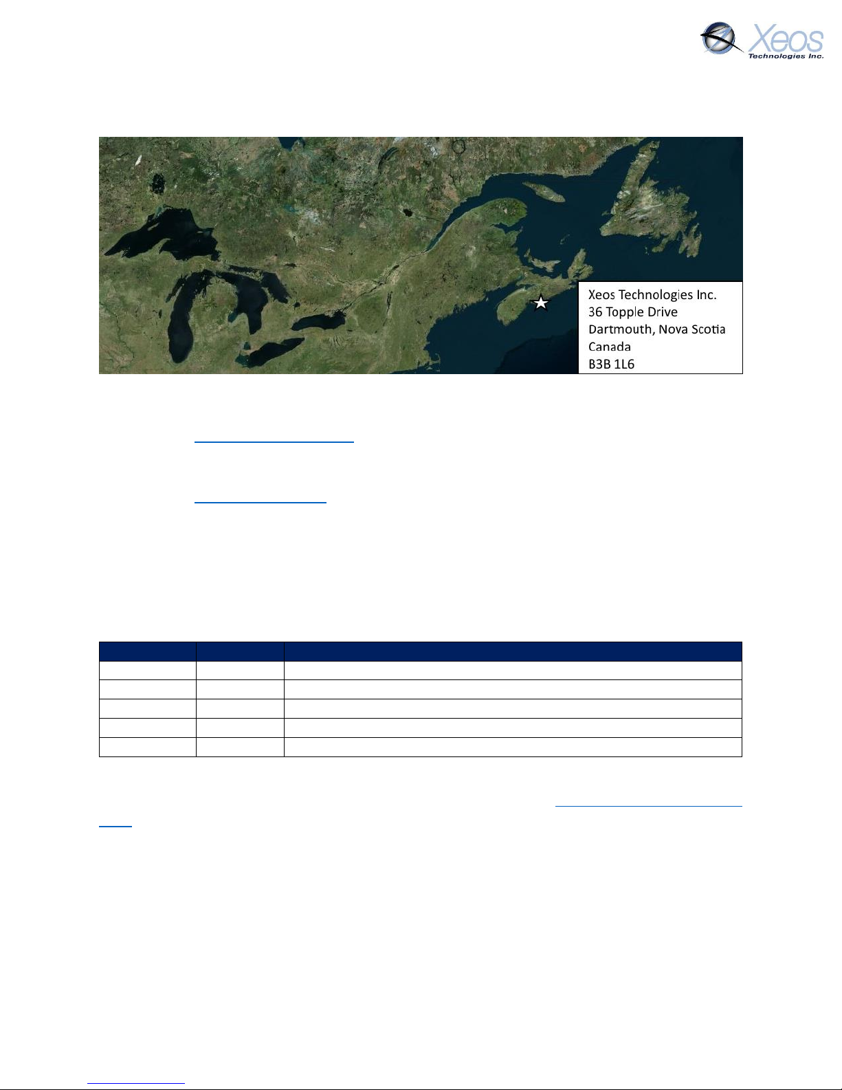
Shipped From
Contact Us
Email
Phone
(902) 444-7650
Fax
(902) 444-7651
Website
www.xeostech.com
Specifics
This manual version is written with respect to OSKER firmware build 5123. If you wish to acquire
the latest firmware for your device, contact [email protected]
Version History
Version No.
Date
Description
1.0
Nov 2015
Initial document
2.0
Jun 2017
Updated magnet switch details
2.1
Apr 2018
Re-formatting, standardized commands
2.2
Apr 2018
Rewrote Understanding Position Information Section
3.0
Mar 2019
Overhaul, expanded message formats
Regular checks for the latest manual are suggested. Be sure to check Xeos Technologies’ manuals
page to compare versions and download the latest version.
Page 3

OSKER User Manual Version 3.0 3
Table of Contents
Shipped From .................................................................................................................................. 2
Contact Us ....................................................................................................................................... 2
Specifics ........................................................................................................................................... 2
Version History ................................................................................................................................ 2
General Description ........................................................................................................................ 5
Preliminary Setup ............................................................................................................................ 5
Front Diagram ............................................................................................................................ 5
Setting up an Iridium Account .................................................................................................... 6
Understanding Position Information .............................................................................................. 7
Iridium Doppler position ............................................................................................................ 7
Global Positioning System .......................................................................................................... 8
OSKER Operation ............................................................................................................................ 9
Using the Magnets ..................................................................................................................... 9
Messages From the OSKER ........................................................................................................... 10
Version (Type V) ....................................................................................................................... 10
Position Message ..................................................................................................................... 10
Compressed Binary Position ................................................................................................ 10
ASCII Position (Type P) ......................................................................................................... 11
Status Change Message (Type S) .............................................................................................. 12
Information Message (Type I) .................................................................................................. 12
Communicating with the OSKER ................................................................................................... 13
Sending Commands via Email ....................................................................................................... 13
Command Format .................................................................................................................... 13
Command Structure ................................................................................................................. 13
The Unlock Code ...................................................................................................................... 14
Sending a Command ................................................................................................................ 14
Sending Commands Using XeosOnline ......................................................................................... 15
Setting up to Send .................................................................................................................... 15
Xeos Beacon Bluetooth App ......................................................................................................... 15
Messages to the OSKER ................................................................................................................ 16
Settings ..................................................................................................................................... 16
Page 4

OSKER User Manual Version 3.0 4
Lifetime Stats ............................................................................................................................ 17
Stats .......................................................................................................................................... 17
The OSKER’s Timers ...................................................................................................................... 18
Timer Types .............................................................................................................................. 18
SBD ....................................................................................................................................... 18
GPS ....................................................................................................................................... 18
OSKER Timer Modes ................................................................................................................. 18
Start-up Mode ..................................................................................................................... 18
Normal Mode ....................................................................................................................... 18
Alarm Mode ......................................................................................................................... 18
No-GPS-Fix Mode ................................................................................................................. 18
Default Settings ........................................................................................................................ 19
The Timer Command ................................................................................................................ 19
Changing the Timers ................................................................................................................. 20
Watch Circle .................................................................................................................................. 21
Enabling the Watch Circle ........................................................................................................ 21
Setting the Watch Circle ........................................................................................................... 21
Example: .............................................................................................................................. 21
Enable Inversion Events ................................................................................................................ 22
Message Enable ............................................................................................................................ 22
Other Commands .......................................................................................................................... 23
Installation and Maintenance ....................................................................................................... 24
Pre-deployment Storage .......................................................................................................... 24
Deployment .............................................................................................................................. 24
Recovery ................................................................................................................................... 24
Appendix A: Technical Specification ............................................................................................. 25
Appendix B: Engineering Diagrams ............................................................................................... 26
Appendix C: GPS Text Long ........................................................................................................... 27
Warranty, Support and Limited Liability ....................................................................................... 28
Page 5

OSKER User Manual Version 3.0 5
General Description
Reliable, continuous information from the ocean’s surface can be difficult to gather. The OSKER
(Oil Spill Kit Emergency Response) provides global communications via the Iridium satellite
system in a small, rugged package with sophisticated on-board programming.
The OSKER makes use of the bi-directional, global, real time Iridium Satellite Short Burst Data
(SBD) network in combination with GPS position location. Inside the OSKER is a 9603 Iridium
Satellite Short Burst Data core radio transceiver, a specialized low power Xeos digital controller
with GPS, and hard-wired battery package.
When deployed in a group, the OSKERs provide accurate real time tracking over an area of the
surface, mapping currents, oil spills, or other phenomenon. Users can set the Watch Circle with
a radius of up to 15km to get automatic notification if any of the units travel outside of a
designated area.
See www.xeostech.com for details or call (902) 444-7650.
Preliminary Setup
Front Diagram
The front of the OSKER has pertinent information beneficial not only to the user, but any
individual that may find the device after deployment.
FIGURE 1: TOP-DOWN DIAGRAM OF DATA DISPLAYED ON AN OSKER
1
View the Green LED on power-up or later to confirm that the device is on
2
Xeos Technologies will insert contact information of the customer’s choosing here.
Customers can also request Xeos Support be the contact information inserted.
3
The IMEI of the device as well as the production Serial Number (in smaller text) is here
4
The OSKER is capable of command and updates via the Xeos Bluetooth App
5
Scan the QR Code to receive the link to the Xeos Manuals page
Page 6

OSKER User Manual Version 3.0 6
Setting up an Iridium Account
OSKER makes use of the Iridium Satellite Systems’ Short Burst Data (SBD) service for the 9603
transceiver. This service is a global (including the Polar Regions), two-way, real-time and emailbased data delivery service with a maximum outbound (from beacon) message size of 340 bytes
and a maximum inbound (to beacon) message size of 270 bytes.
OSKER end users must set up an approved data delivery account with their preferred service
provider. This can only be done once Xeos has provided the user with an International Mobile
Equipment Identity (IMEI) number. Each 9603 modem has a unique IMEI that must be registered
with the preferred service provider. For a list of service providers in your area please contact
Iridium for recommendations. Xeos Technologies is also able to provide Iridium SBD data service
and accounts. Please contact [email protected] for more information.
Each IMEI number is capable of being associated with up to five (5) unique email addresses (this
may vary between service providers). When registering an IMEI number, please provide the
service provider with a temporary Xeos testing account email address.
This account is: [email protected]
This temporary email testing account can be deleted or replaced at any time after delivery of the
OSKER. Once the SBD account has been activated, please contact your Xeos representative and
confirm this.
OSKER makes use of a simple and robust binary email protocol as the default outgoing message
format. Any email application can be used to send and receive messages to or from the OSKER,
however, the messages from the OSKER in this format are not human-readable. XeosOnline is a
web-based monitoring system which allows users to view and manage information from the
OSKER on a mapping system, as well as view the messages in a human-readable format.
XeosOnline also allows for the creation of multiple kinds of message forwarders which can
forward certain (or all) messages to a group of email addresses in a human-readable form.
Sending messages and changing configuration can be completed through XeosOnline. See
www.xeostech.com or your account manager for more information.
Page 7
OSKER User Manual Version 3.0 7
Understanding Position Information
There are two types of position information which will be sent via the Iridium Gateway.
Iridium Doppler position
The Iridium Gateway calculates the Iridium transceivers’ position on earth when it receives a
transmission, using Doppler technology. As a result, it is often very inaccurate. This location is
only visible to users getting emails directly from the device, as opposed to emails forwarded by
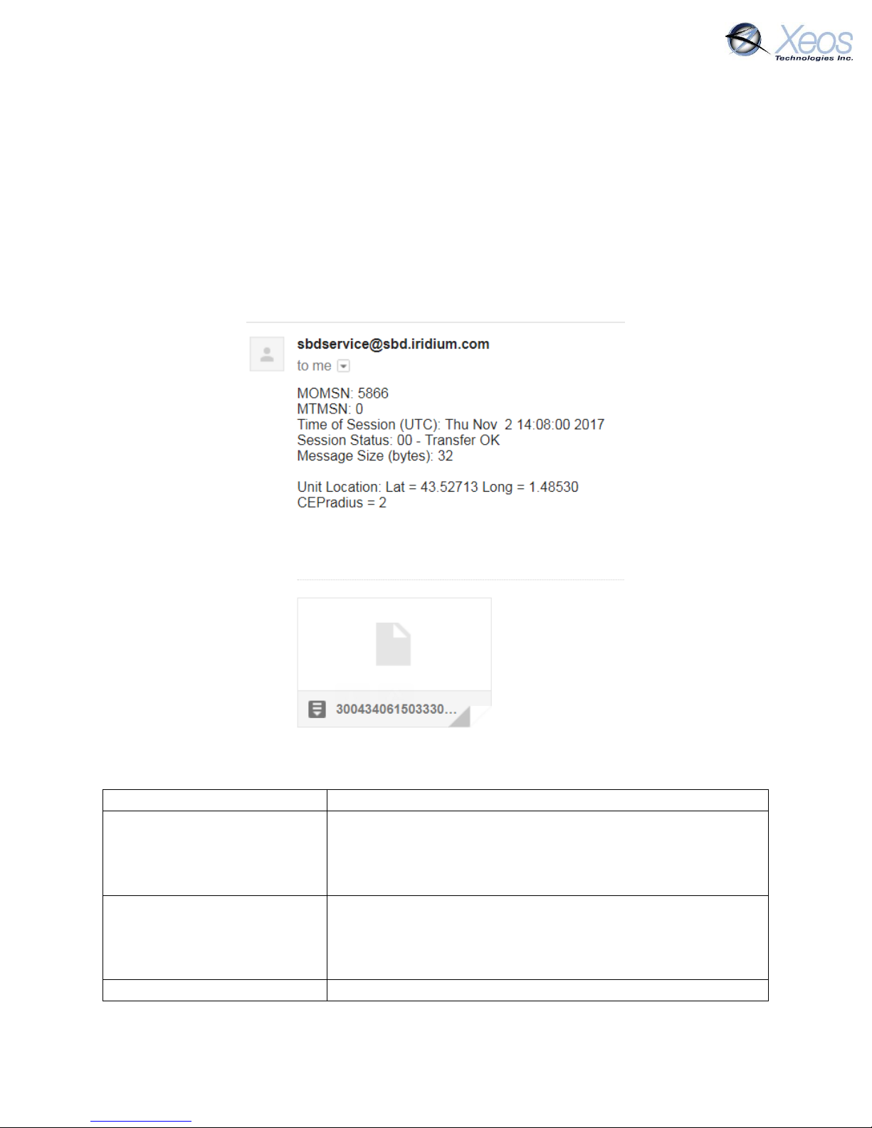
XeosOnline. An example of a “raw” Iridium message via email is below and will always have the
IMEI of the device in the subject line, regardless of its name on XeosOnline.
FIGURE 2: AN EXAMPLE OF A RAW IRIDIUM MESSAGE FROM A DEVICE VIA EMAIL
All messages from Iridium devices come from this address.
MOMSN: 5866
Mobile Originating Message Serial Number; each individual
message has its own incrementing serial number. A mobile
originating message is one that comes from the Iridium
device.
MTMSN: 0
Mobile Terminating Message Serial Number; like the MOMSN,
messages to Iridium devices (like commands) also have an
incrementing serial number. Since the message in the
example is from an Iridium device, the MT number is zero.
Time of Session (UTC)
The time the message arrived at the Iridium Gateway
Page 8

OSKER User Manual Version 3.0 8
Session Status
Each message will have a code determined by how well the
message was received; codes 00, 01 and 02 are acceptable
and will always have their code name (ex. Transfer OK) next to
this number.
Message Size (bytes)
The size of the actual message sent by the Iridium device,
which is in the attachment in the email.
*Unit Location
The Doppler position of the device as estimated by Iridium’s
network. It is NOT the GPS position measured by the device.
*CEPradius = 2
The numerical value of how accurate the above position is;
with a value of 2, This means that using the Lat/Long that the
body has supplied, Iridium is 80% confident (always 80%) that
the device sending the message is within a circle, 2 kilometers
in radius, with the Lat/Long given as the centre of that circle.
The higher the CEPradius value, the larger the circle and
therefore the less accurate that position.
* These items can be enabled/disabled by your Iridium provider if desired.
Global Positioning System
Location information generated by the device itself is embedded in the SBD attachment sent via
the Iridium Gateway and can only be seen through the XeosOnline system or situations where
the position information is sent in a plain-text format (XeosOnline message forwarder or using
the $msgenable command). This position information is accurate to within several feet of the
true position.
Page 9
OSKER User Manual Version 3.0 9
OSKER Operation
As a free-floating drifter, the OSKER is designed to regularly transmit its position despite its
orientation, while being easily deployed from the air or from a marine vessel on demand. If no
changes are made to operation, the OSKER will transmit one position every ten minutes until its
batteries are expended. While deployment life varies depending on the time it takes to transmit
information (quality of reception) the OSKER typically sends a minimum of 1500 messages to a
full deployment (battery depletion).
Using the Magnets
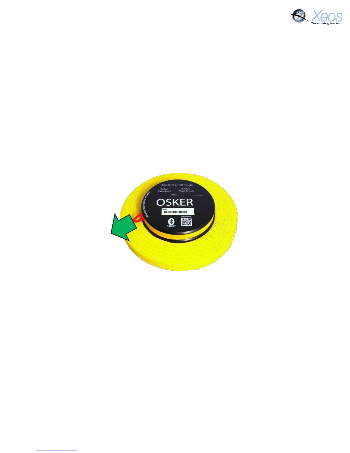
A magnetic tab embedded into the side of the OSKER’s enclosure keeps the device’s power
source disengaged from the electronics. Remove the breakaway tab to turn on the OSKER.
• A solid FLASHING GREEN LED indicates that the OSKER is powering on
To turn the OSKER off, return the magnet that was attached to the OSKER to its place along the
side of the enclosure.
Note: It is important to let all LEDs stop illuminating before initiating another action.
Note: Cycling power for any reason, for example by using the switch to turn OFF/ON, will
initiate Start-up Mode.
FIGURE 3: REMOVE THE MAGNETIC TAB TO TURN ON THE OSKER
Page 10
OSKER User Manual Version 3.0 10
Messages From the OSKER
There are several messages sent from the OSKER, depending on setup and conditions. Below are
examples of the most common Mobile Originating messages.
Version (Type V)
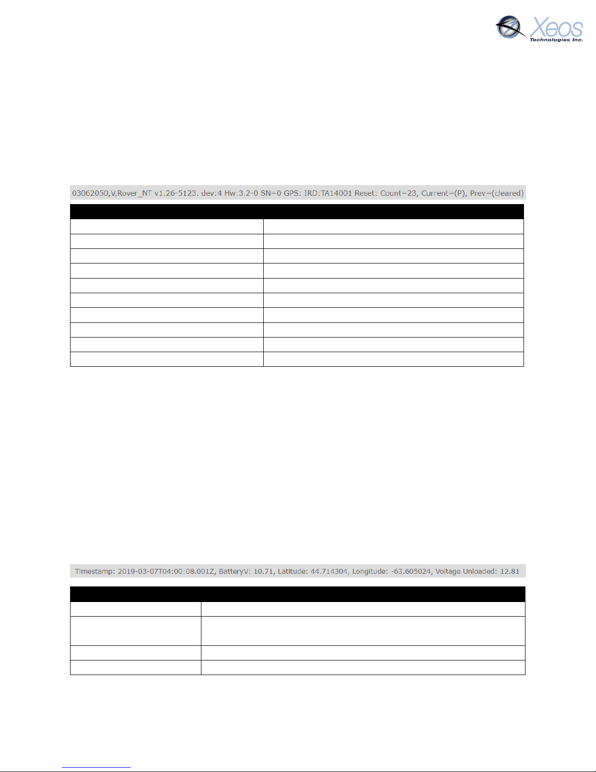
The Version message is sent upon start-up of the OSKER, from both hard and soft resets. It can
also be called upon using the $ver command.
Version Readout
03062050
Indicates the device has started a new power cycle
V
Identifier for the Version message
Rover_NT v1.26-5123 dev:4
Product; Major, minor, build of firmware
Hw: 3.2-0
Hardware revision, set during assembly
SN=0
The unit’s serial number
GPS
Firmware version of GPS chip
IRD
Firmware version of Iridium modem
Reset: Count=23
The number of resets since firmware was uploaded
Current=(P)
Cause of last power off
Previous=(cleared)
Cause of previous power off, not used in OSKER
Position Message
Typical position messages are sent in compressed binary format (Message Type 10) to save on
data usage and are parsed in XeosOnline. If XeosOnline is not used, GPS Text Short (Message
Type 0) can be used to read position messages as P-Type.
Compressed Binary Position
The default format for positions is compressed to save on Iridium data usage. This binary format
is parsed into a readable format by XeosOnline, placing its full contents in the Message and
Location Logs.
The binary format is stackable and can transmit more than one position per Iridium transmission.
In this situation, all recorded positions will be displayed in the Location Log, while the latest
position will be displayed in the Message Log.
Message Log Readout
Timestamp
Date and time in UTC of the latest position reading
BatteryV: 10.71
Loaded voltage of the power supply; minimum battery voltage
observed during the previous Iridium transmission
44.714304
Latitude of fix, decimal degrees
-63.605024
Longitude of fix, decimal degrees
Page 11
OSKER User Manual Version 3.0 11
Voltage Unloaded: 12.81
Unloaded voltage of power supply; battery voltage data from
measurement taken just prior to the turning on of the Iridium
modem
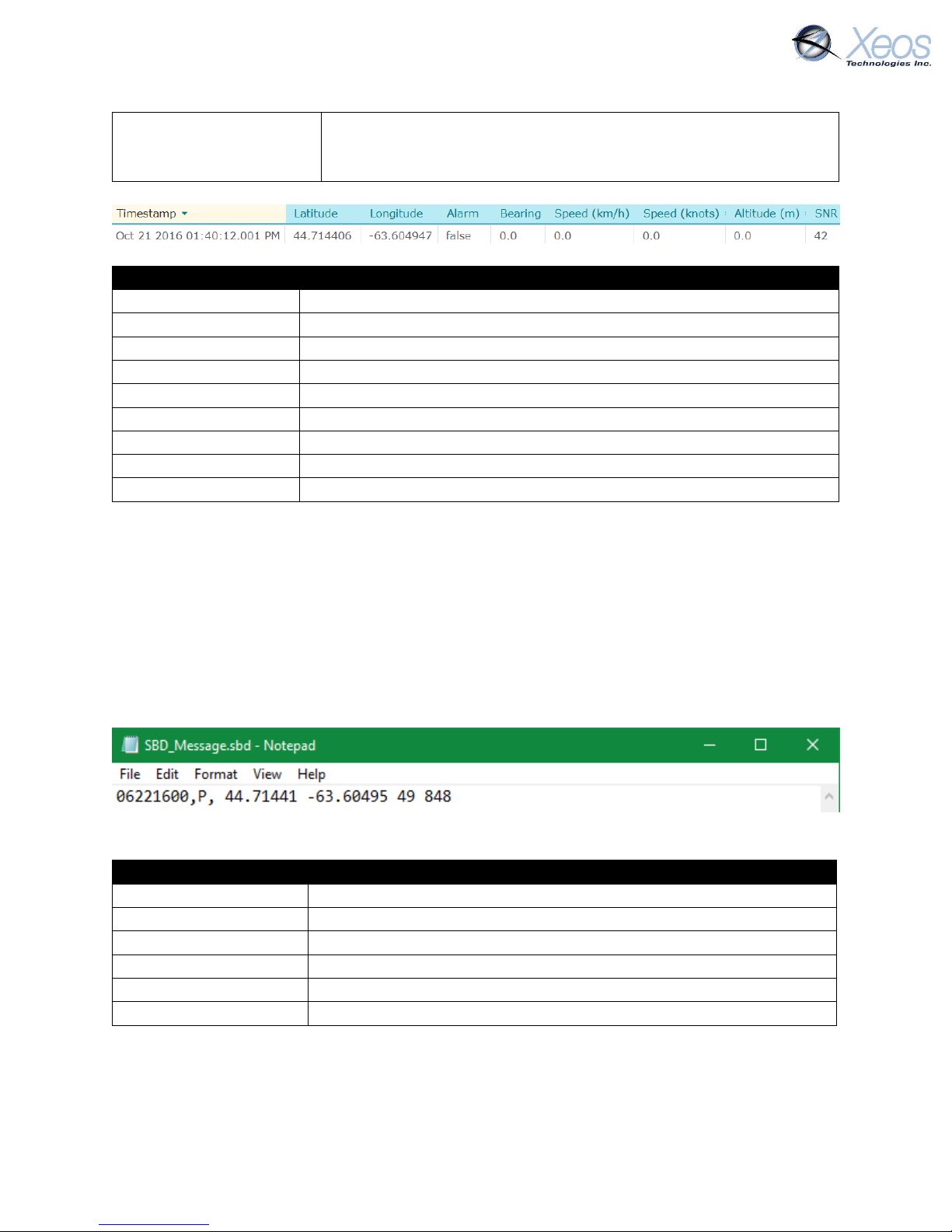
Location Log Readout
Timestamp
Date and time in UTC of this specific position reading
44.714406
Latitude of fix, decimal degrees
-63.604947
Longitude of fix, decimal degrees
Alarm: False
Indicates if the device has determined if it is in an alarm state
Bearing
Direction of movement determined by device
Speed (km/h)
Speed measurement in kilometers per hour
Speed (knots)
Speed measurement in knots
Altitude
Not used
SNR
SNR (Signal-to-noise ratio) of GPS Fix, higher is better (>37 is good)
Each compressed message is 26 bytes in size, with an additional 11 bytes added for each
additional “stacked” position.
ASCII Position (Type P)
In ASCII position format, only the most recent fix is sent at each interval, therefore it is most
efficient to have GPS and Iridium intervals equal. This message also appears as it is shown below
in XeosOnline.
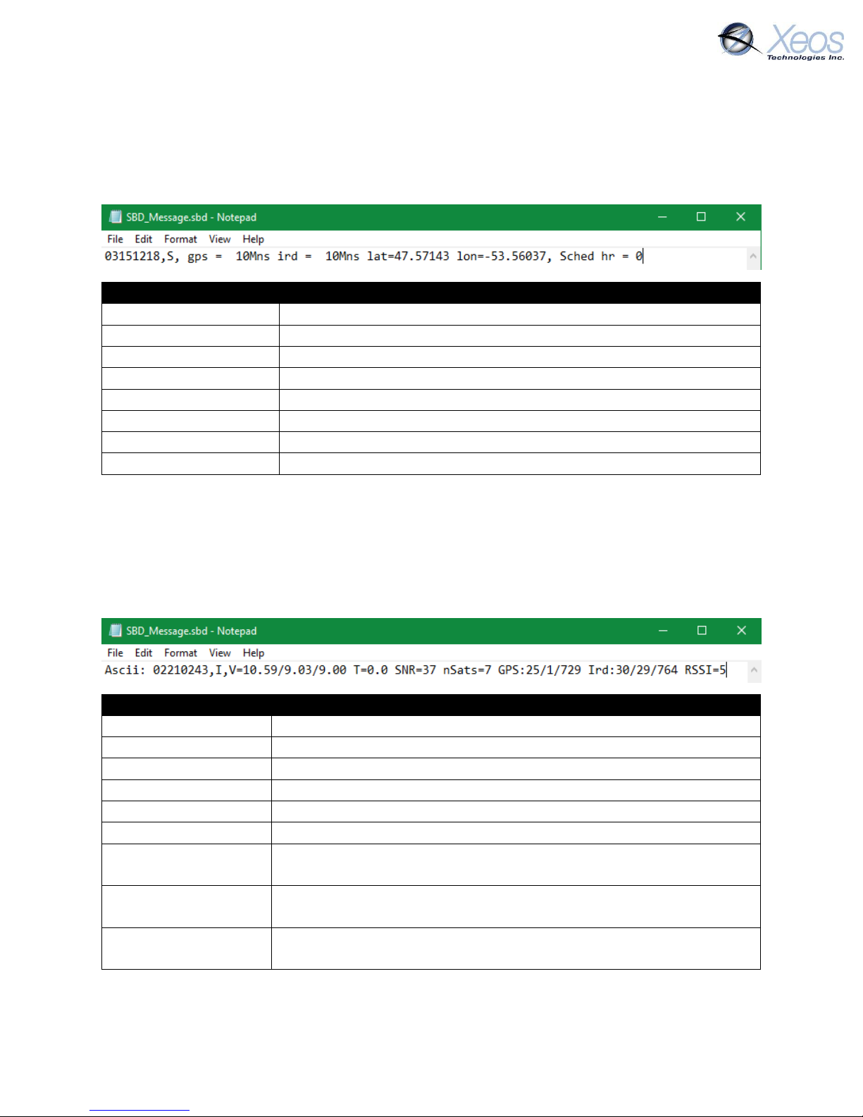
P-type messages are approximately 39 bytes, but can be larger if Watch Circle is enabled:
The message type used can be changed using the $msgenable command.
Position Readout
06221600
Timestamp in UTC (Month/Day/Hour)
P
Type of message (Position)
44.71441
Latitude of fix, decimal degrees
-63.60495
Longitude of fix, decimal degrees
49
SNR (Signal-to-noise ratio) of GPS Fix, higher is better (>37 is good)
848
Unloaded voltage of device at the time of GPS Fix in mV
Page 12
OSKER User Manual Version 3.0 12
Status Change Message (Type S)
Status messages are sent from the device when there has been a change to the operation of the
device, whether a timing change between modes (Start-up mode to Normal mode). This message
is always sent in ASCII format.
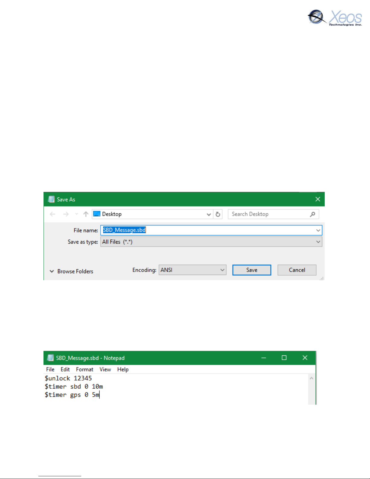
Status Readout
03151218
Timestamp in UTC (Month/Day/Hour)
S
Type of message (Status Change)
Status / Value Change
Indicates that a setting has been changed
gps = 10Mns
Currently used GPS repetition rate
ird = 10Mns
Currently used Iridium repetition rate
lat=47.57143
Latitude of latest fix
lon=-53.56037
Longitude of latest fix
Sched hr = 0
Timing offset of Iridium/GPS sessions from UTC, set via $reporthour
Information Message (Type I)
In situations where the device fails a GPS session through low SNR or other factor, the follow-up
Iridium session will send a synopsis of the latest statistics from the device. This message will
always be in ASCII format regardless of message format settings and approximately 80 bytes.
This message can be prompted using $sysinf
Information Readout
02210243
Timestamp in UTC (Month/Day/Hour)
I
Type of message (Information)
V=10.59/9.03/9.00
Battery voltages unloaded/after Iridium session/after GPS session
T=0.0
Most recent temperature measurement, not used in OSKER
SNR=37
MaxSNR (Signal-to-Noise ratio) of the last GPS attempt
nSats=7
Number of connected satellites during last GPS attempt
GPS:25/1/729
Quantity of good fixes since powerup, fails/Quantity of failed fixes/
Seconds total GPS has been powered on since power-up
Ird:30/29/764
Quantity of Iridium messages/Quantity of Iridium sessions/ Seconds
total on time for Iridium
RSSI=5
Value reported back from the modem. Always a number
between zero and five; five being the strongest signal.
Page 13
OSKER User Manual Version 3.0 13
Communicating with the OSKER
There are 3 ways to communicate with the OSKER:
1. Over-the-air with Email SBD messages
2. Over-the-air with XeosOnline
3. Locally with Bluetooth
Sending Commands via Email
To receive commands from the Iridium network, the device in use must have a clear view of the
sky. If the device is unable to communicate with the Iridium network, commands will remain
queued for five days.
Command Format
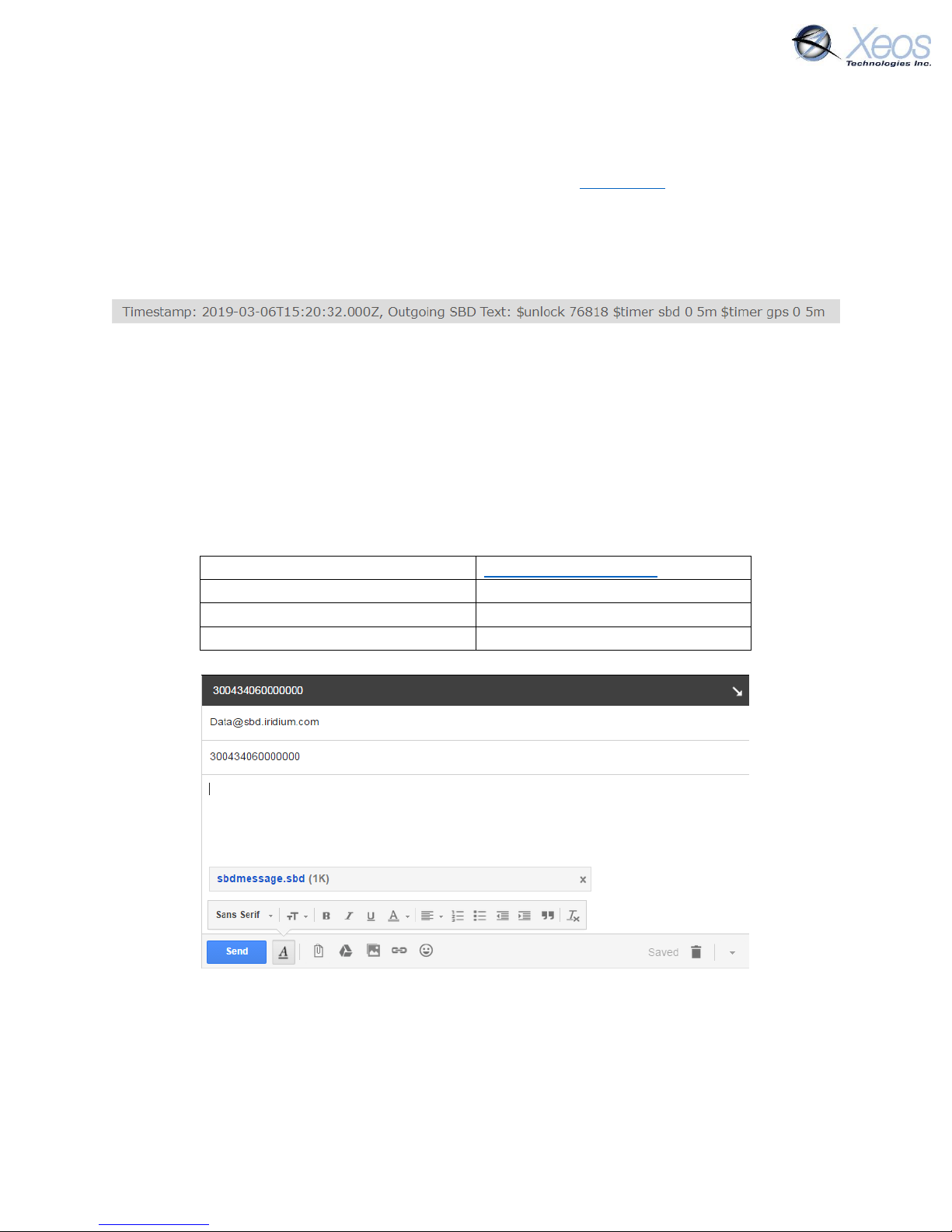
CREATING THE FILE
To create an SBD command, open a new file in a text editor (ex. Notepad) and save it using the
.sbd extension. Make sure the Save as type option is set to All Files to achieve this.
Command Structure
Commands must be structured in the following way:
1. Each command MUST have a dollar sign ($) before each command.
2. The device’s unlock code in the following format: $unlock XXXXX
where XXXXX is the unit’s five digit unlock code.
3. A list of commands, one command per line.
Page 14
OSKER User Manual Version 3.0 14
The Unlock Code
SBD commands without an unlock code will be ignored by devices that require it. The unlock code
is generated by the device itself and can be retrieved from XeosOnline, or can be queried by
sending $unlock to the device as a command. The device will respond by sharing the 5-digit code
with its provisioned destinations.
Navigate to your unit on XeosOnline and click on the Message Log Tab. You will see the unlock
code in the most recent outgoing messages.
Once XeosOnline has a device’s unlock code, all outgoing commands will have the code added at
the beginning of the message.
The unlock code will only be changed if the firmware is updated, or if commanded via:
$unlock XXXXX YYYYY
Where XXXXX is the current code, and YYYYY is the new code to be used in the future.
Sending a Command
To send your .sbd command, create a new email message with the following fields:
To
Subject
Your device’s IMEI
Body
Empty
Attachments
Your .sbd file
A confirmation will be immediately returned from the Iridium Gateway from the address
[email protected] indicating that your message is now in the message queue. It will
be delivered to the device during the device’s next Iridium check.
Commands can be sent from any email address, but responses will be returned only to email
addresses on the unit’s forwarding list.
Page 15
OSKER User Manual Version 3.0 15
Sending Commands Using XeosOnline
Before using XeosOnline make sure that your account has been set up and your device added to
your organization. Contact [email protected] for more information.
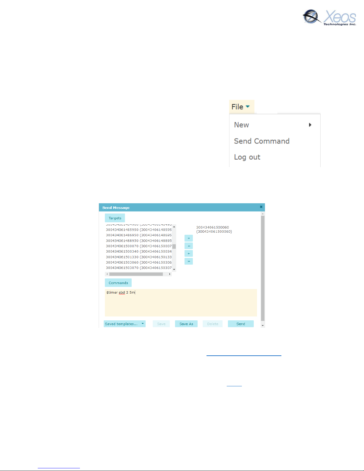
Setting up to Send
Navigate to the Send Command window.
From the Home Tab, choose
File > Send Command
Select the units you wish to target with commands and move
them over to the right-hand target list using the -> button. Type
your command(s) into the command box and press send.
Remember to include the dollar sign ($) ahead of each
command and enter each command on a separate line.
Outgoing messages will appear in the Message Log for the commanded device.
Xeos Beacon Bluetooth App
Select Xeos products can be configured locally using the Xeos Beacon Android App. This method
of communication requires no disassembly.
The Bluetooth app allows for communication, configuration, logging and firmware updates. A
detailed document on how to use the application can be found here.
Page 16
OSKER User Manual Version 3.0 16
Messages to the OSKER
Settings
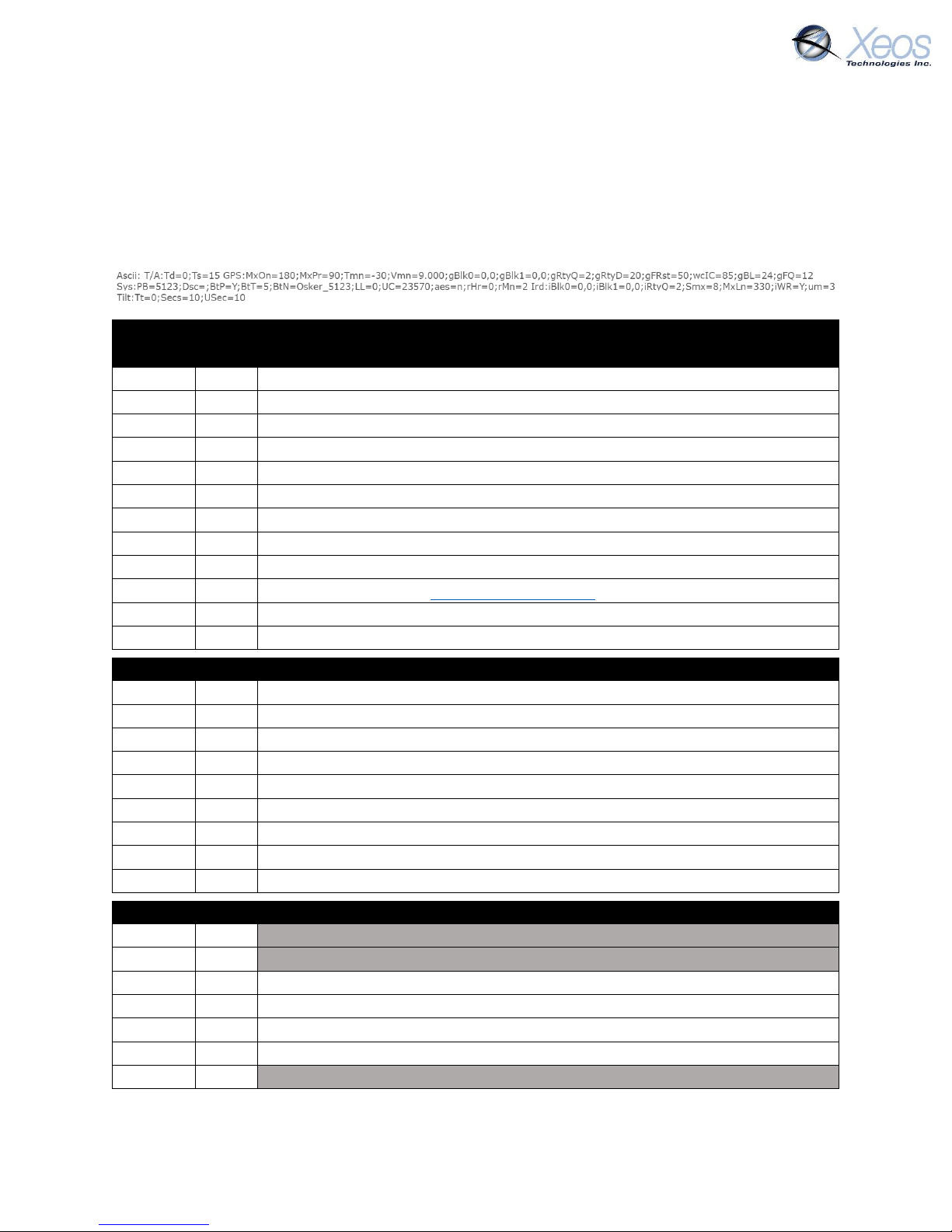
The $settings command will return a truncated list of important OSKER settings aside from
timers with their current values. Changing any of these values WILL impact performance.
Greyed out sections are unused by the OSKER.
Name Default Description
GPS Settings (GPS)
MxOn
180
Maximum GPS session length in seconds
MxPr
90
Maximum GPS session length in poor conditions
Tmn
-30
Temperature minimum
Vmn
9.000
Voltage minimum
gBlk0
0,0
GPS Blackout, unused
gBlk1
0,0
GPS Blackout, unused
gRtQ
2
GPS retry quantity
gRtyD
20
GPS retry delay in seconds
gFRst
50
Number of GPS failures for GPS reset
wcIC
85
WC Inner Percent for WC Warning message (Val = % of WC Radius)
gBL
24
Maximum saved GPS fixes
gFQ
12
Maximum GPS fixes per message
System Settings (Sys)
PB
Build
Firmware Build
BtP Y Bluetooth on or off
BtT 5 Bluetooth Timeout in minutes
BtN
Name
Bluetooth Name
LL 0 Diagnostic Log detail level
UC
Code
Unlock Code
aes N AES Encryption enabled yes/no
rHr
0
Hour on which timings are based (24h UTC)
rMn
2
SBD hour offset in minutes
Iridium Settings (Ird)
iBlk0
0,0
Iridium Blackout, unused
iBlk1
0,0
Iridium Blackout, unused
iRtyQ
2
SBD Retry Quantity
Smx
8
Maximum SBD attempts per Iridium session
MxLn
330
Maximum message length (bytes)
iWR
Y
Wait for registration with Iridium network to send data
um 3 Unsolicited messages
Page 17
OSKER User Manual Version 3.0 17
Tilt Settings (Tilt)
Tt 0 Tilt Threshold
Secs
10
Tilt Seconds
USec
10
Untilt Seconds
Lifetime Stats
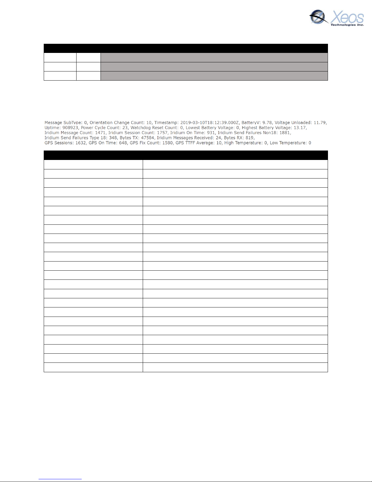
The $statsl command will return various performance statistics recorded since the last firmware
install, over all resets.
Lifetime Statistics Readout
Orientation Change Count
Number of OSKER flips registered
Timestamp
Date and time of message
BatteryV
Last measured loaded battery voltage
Voltage Unloaded
Last measured unloaded Voltage
Uptime
Total unit uptime in minutes
Power Cycle Count
Number of power cycles
Watchdog Reset Count
Number of errors
Lowest Battery Voltage
Lowest measured battery voltage
Highest Battery Voltage
Highest measured battery voltage
Iridium Message Count
The number of SBD messages queued for sending
Iridium Session Count
Total successful Iridium connections
Iridium On Time
Total successful Iridium connections on first try
Iridium Send Failures Non18
Iridium failures, excluding RF drop
Iridium Send Failures Type18
Iridium failures due to RF drop
Bytes TX
Sum of all data sent in Bytes
Iridium Messages Received
Successfully received SBD messages
Bytes RX
Sum of all data received in Bytes
GPS Sessions
Total GPS attempts
GPS On Time
Total successful GPS fixes on first try
GPS Fix Count
Successful GPS fix count
GPS TTFF Average
Average time to fix (Seconds)
High Temperature
Not used with the OSKER
Low Temperature
Not used by the OSKER
Stats
The $stats command will return performance statistics recorded since the last power up. The
statistics are those found in $statsl, but exclude Power Cycle Count and Watchdog Reset Count.
Page 18

OSKER User Manual Version 3.0 18
The OSKER’s Timers
Timer Types
SBD
The OSKER will communicate with the Iridium Gateway based on this interval. If the OSKER
successfully registers with the Iridium Satellite Constellation, it will send any messages queued
for transmission. Once this is finished and the queued outgoing messages have been
implemented, the OSKER will receive any queued commands from the Iridium Gateway.
GPS
The OSKER will communicate with the GPS network and get a location fix based on this interval.
Any successful GPS fixes will be queued for the next Iridium transmission. The OSKER’s real-time
clock will also be set and adjusted based on the GPS network. The GPS interval will execute before
the SBD interval if they are scheduled for the same time.
OSKER Timer Modes
Start-up Mode
Start-up mode (Timer 1) will begin when the OSKER is turned on via magnet removal, or if the
OSKER is reset by an SBD command. This mode will last for one hour, after which the OSKER will
enter Normal mode.
Normal Mode
Once Start-up mode has finished, the OSKER will enter Normal mode (Timer 0). This is the default
timer mode of the OSKER and will be used if no other modes apply. At default settings, the OSKER
will transmit 1 GPS fix every 10 minutes. If no other modes are engaged, the OSKER will continue
in normal mode until its batteries are depleted or the unit powered off.
Alarm Mode
If a watch circle has been set, the OSKER will enter Alarm Mode (Timer 2) when it exits the set
radius or when the device detects it has been inverted on its GPS interval (if enabled).
While in watch circle alarm mode, the OSKER will send information pertaining to the Watch Circle
with each message, such as distance from centre and the duration in minutes that the device has
been in that mode.
If the device enters Alarm Mode due to inversion, the device will send an Orientation Change
Message (see Stats message) at each point that it has changed its antenna used for transmission.
No-GPS-Fix Mode
If the OSKER is unable to get a GPS fix after repeated attempts, it will transmit a GPS Failure
message and move to this timer mode (Timer 4).
Page 19
OSKER User Manual Version 3.0 19
Default Settings
Timer
T0
<T1>
T2
T3
T4
Min-Max
SBD
10m
10m
10m
10m
10m
5m – 1d
GPS
10m
10m
5m
10m
10m
5m – 1d
Legend
SBD
SBD (Iridium) transmission interval
GPS
GPS acquisition interval
T0 – T7
Timer number
<T#>
Timer currently in use
#s/m/h/d
Interval in seconds/minutes/hours/days
Min
Minimum interval allowed for this timer
Max
Maximum interval allowed for this timer
Timers
Timer 0
Normal
Used if none of the following modes are triggered
Timer 1
Start-up
Used for the first hour after the unit is powered on or reset
Timer 2
Alarm
Used once the unit’s watch circle is triggered
Timer 4
No GPS Fix
Used when the GPS module consistently fails to acquire a fix
While the timers are able to be manipulated to the user’s liking, by default the OSKER is
programmed to transmit in a consistent manner no matter the case.
The Timer Command
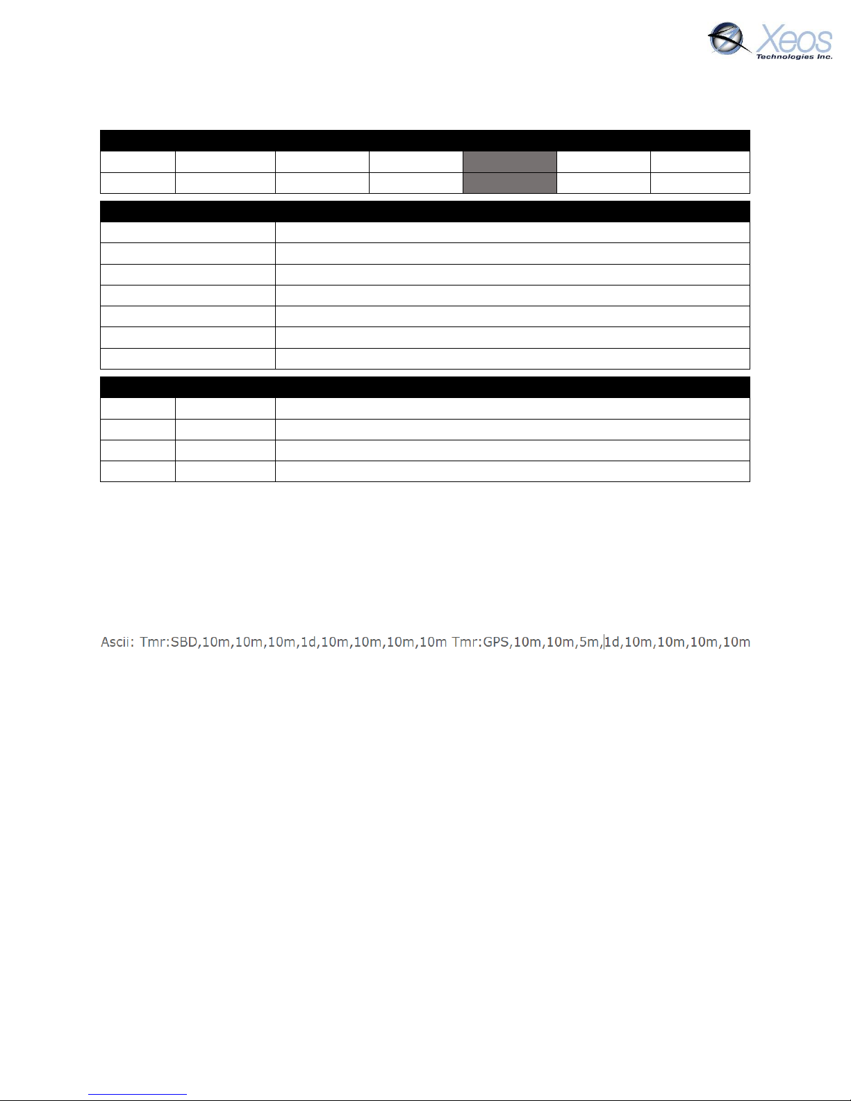
The $timer command will return the timer intervals of the current mode. This response will also
be returned when timers are changed.
The timer string returned includes a summary of GPS and SBD timers. The first five timers are
used by the OSKER:
Timer 0 (Normal mode)
Timer 1 (Start-up mode)
Timer 2 (Alarm mode)
Timer 4 (No-GPS-Fix mode)
The last 3 timers are unused by the OSKER and can be ignored.
Page 20
OSKER User Manual Version 3.0 20
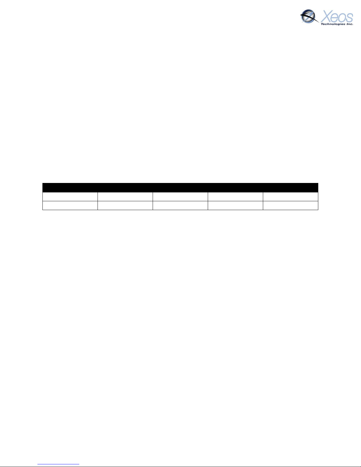
Changing the Timers
The length of the OSKER’s various modes cannot be altered. Start-up mode is fixed at 1 hour.
However, the Iridium and GPS intervals can be changed to suit the user’s requirements.
The GPS and Iridium interval timers can be set independently of each other, but there are several
things to keep in mind. The OSKER has a limit of 24 GPS fixes per Iridium message and will retain
a maximum of 40 unsent fixes. This puts a practical limit on the ratio of GPS fixes to Iridium
checks.
Regardless the method being used to communicate with the OSKER, timer commands are always
the same format:
$timer SYSTEM TIMER-MODE INTERVAL
Typed out as:
$timer SBD 0 2h
Command
Timer
Mode
Interval
Example 1
$timer
GPS
0
1h
Example 2
$timer
SBD
0
6h
Example 1 would change the GPS interval of Normal mode to every hour, while Example 2 would
change the SBD message interval to 6 hours. After sending the commands from both Example 1
and Example 2, the user would receive 1 message every 6 hours containing 6 GPS fixes. These
messages would be sent at approx. 00:00 UTC, 06:00 UTC, 12:00 UTC and 18:00 UTC.
Page 21

OSKER User Manual Version 3.0 21
Note:
If a watch circle is not set by command, but
functionality is enabled, the OSKER will average its
GPS location fixes for 48 hours, creating a Watch Circle
using the average position as its centre the default
radius of 100m.
Watch Circle
The watch circle functionality allows users to monitor the position of their mooring by receiving
alarm messages when it exits a user-defined circle. This feature aids in the recovery of moorings
that could break free from their planned position.
Recognition of a watch circle exit is tied to the GPS interval of the device in Normal Mode (Timer
0); once a GPS position is logged that shows the device is outside the circle, the device
immediately transitions to Alarm Mode (Timer 2) and transmits according to Alarm Mode timer
intervals.
Enabling the Watch Circle
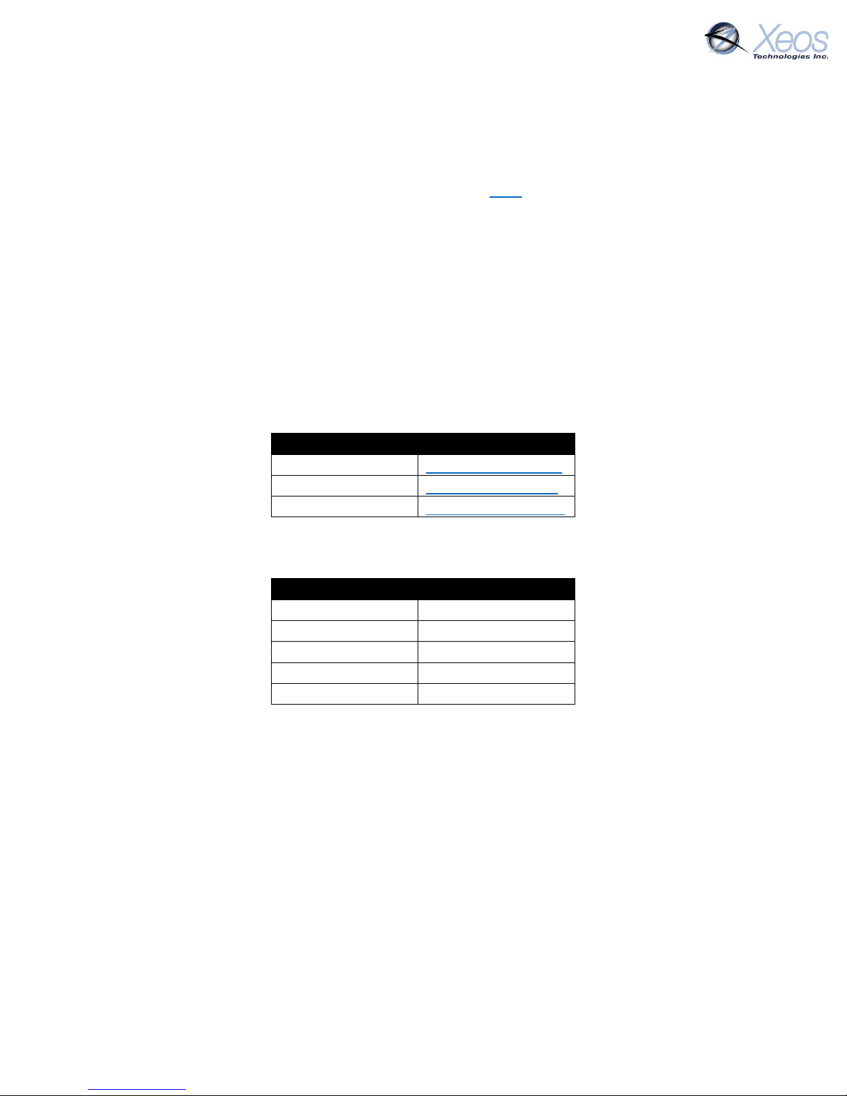
The watch circle is disabled by default, but can be enabled by the following command:
$WCenable 1
The OSKER will return this line, indicating Watch Circle (C) is enabled (Y)
Once functionality is enabled, the specifics of the user’s circle can be implemented.
Setting the Watch Circle
The watch circle parameters can be set by sending the $setcircle command using this format:
$setcircle Latitude Longitude Radius
The minimum Radius is 50 meters, while the maximum is 15000 meters.
Example:
$setcircle 47.56989 -53.55682 100
a) $setcircle is the command
b) Latitude is set to 47.56989
c) Longitude is set to -53.55682
d) Radius is set to 100 meters
Once the watch circle is set, the unit will operate normally until it approaches the watch circle
radius, at which point the device will send a warning message (distance based on the WCInner
value). Once the device exits the watch circle radius, it will begin sending alarm messages with
GPS coordinates every 10 minutes (Timer 2) until the unit re-enters the watch circle, the radius
is expanded via command, or is turned off.
Notes
• A maximum of 24 GPS positions can be included in a single SBD transmission. Unlike other
settings, the watch circle’s details are erased at each power up.
• Watch circle alert, WCInner and inverted mode (if applicable) use the same timer.
• You can adjust the Watch Circle’s radius alone by setting the latitude and longitude
parameters to 0, followed by the new radius.
Page 22
OSKER User Manual Version 3.0 22
Enable Inversion Events
As of 5123, the OSKER no longer transmits automatic Orientation Change messages. Orientation
change messages occur when the device uses a different antenna for GPS acquisition from the
previous acquisition. The message sent is in the form of a Stats message.
To enable this message, use the command:
$evtconfig 2 2 Y
Message Enable
The OSKER has several message types that can be enabled for GPS and event messages. At factory
defaults, the OSKER will send compressed binary GPS (not human readable) and plain text event
(surface and battery) messages. These message formats can be changed using the $msgenable
command.
The OSKER has the following message types available for use:
Message Number
Message Type
0
GPS Plain Text Short
1
GPS Plain Text Long
10
GPS Bin Compressed
At factory defaults, the following message types are enabled for each mode:
Timer Mode
Message Types
0
10 1 10 2 10 3 10 4 10
The $msgenable command must be applied to each timer. The command format must be as
follows:
$msgenable timer message types
To enable GPS plain text short (Type 0), GPS Text Long (Type 1) and GPS Binary Compressed (Type
10) on Timer 0 (Normal mode) you would send the following command:
$msgenable 0 0,1,10
Any number of message types can be enabled for each timer, but for each additional message
type the OSKER will use additional Iridium data.
Page 23

OSKER User Manual Version 3.0 23
Other Commands
Below is a list of other commands that can be sent via Iridium or Bluetooth to acquire additional
information, or configure the OSKER. Remember to add the $ symbol ahead of any commands.
Command
Parameters
Description
ver
---
Show hardware and firmware versions.
Status
---
Show operating status
sysInf
---
GPS/Ird summary
FactoryDefaults
---
Reset all to defaults and reset.
btPwr
1/0
Bluetooth power On/Off
btTOut
Insert Name
Bluetooth timeout (Minutes)
btName
X
Set Bluetooth name for the OSKER
btpcycle
---
Power cycle Bluetooth
batt
---
Show battery status
settings
---
Show all settings.
stats
---
Show statistics (since last powerup/reset)
statsL
---
Show Lifetime Statistics
switch
X 1/0
Switch component X On/Off. No parameter lists
components
MsgEnable
timer#
m1,m2,etc
Set & Show which messages are enabled for each Timer.
ReportHour
Hour (0 –
23)
Set/Show Daily Reporting Hour offset from UTC
RepMinute
X (Minutes)
Minutes offset past the hour for GPS/Iridium
WCEnable
1/0
Watch Circle Enable/Disable
WCInner
X
Watch Circle percent of radius for elevated GPS monitoring
fdumpall
---
Print out Flash Memory of the OSKER (Bluetooth Only)
ResetNow
---
Restarts the system. The effect is the same as restarting via
the magnet
Page 24

OSKER User Manual Version 3.0 24
Installation and Maintenance
Pre-deployment Storage
The OSKER is shipped in an off state with the magnet affixed to its space to preserve battery
power. The unit’s batteries cannot be changed by the user, so turning it off after any test is
necessary to preserve battery life.
Deployment
The intended use of the OSKER is a free-floating tracker, designed to follow the surface currents
of the body it is deployed in. As such it can be deployed quickly as a stand-alone unit without
supplementary equipment.
Additionally, turbulent seas cause the OSKER to flip frequently. The device has two GPS/Iridium
antenna assemblies for such events. Due to this the device can be deployed inverted as well as
label side up.
Finally, most use-cases will require deployment from the sea or air. The OSKER is able to be
deployed from oil rigs, boats and helicopters.
Recovery
Often, OSKERs are recovered from shorelines during or after their deployment life. A space on
the label for the OSKER is for a contact email or phone number if the user wishes to reacquire
the device directly. If the user does not specify contact information, Xeos supplies its own contact
information and will contact the deploying party.
Since the OSKER is not able to be opened, Xeos can, for a fee, refurbish the device with a new
enclosure and battery pack and retest the unit before returning to the customer for a new
deployment.
Page 25

OSKER User Manual Version 3.0 25
Appendix A: Technical Specification
Mechanical
Enclosure Material
Polyvinyl Chloride (PVC)
Dimensions
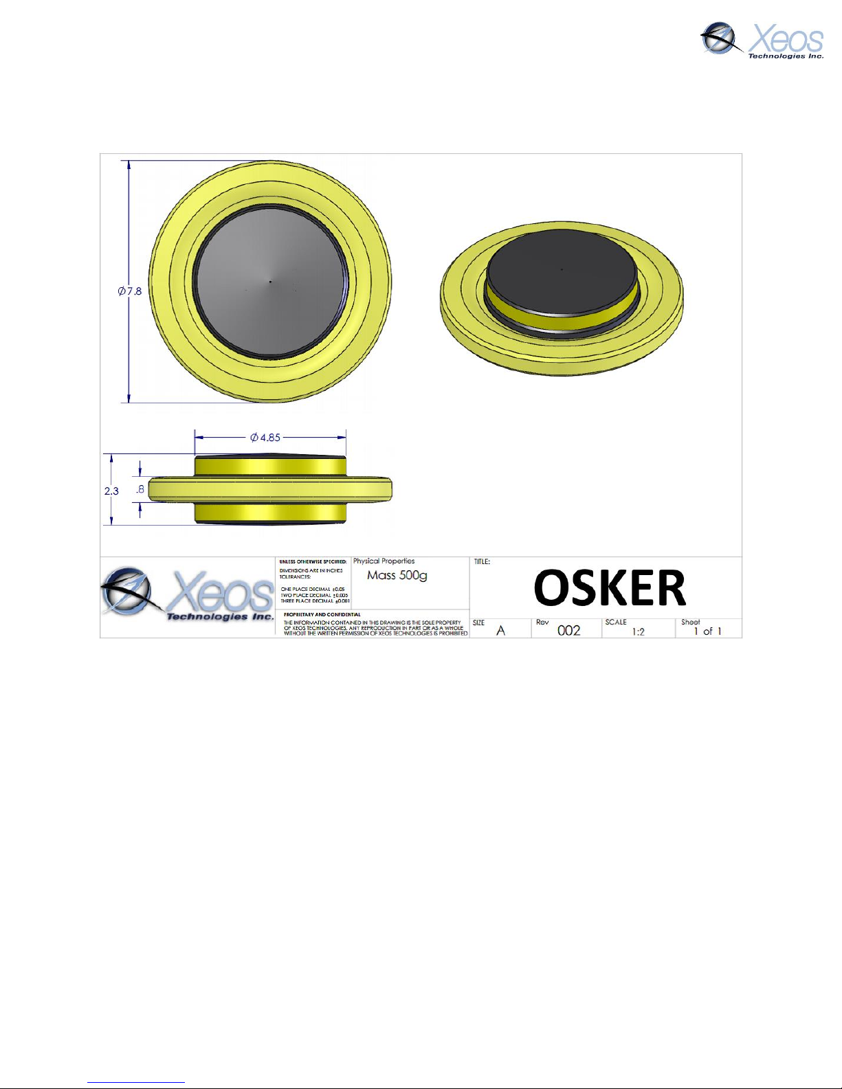
7.8” Diameter x 2.3” Height
Mass
500g – out of water
Electrical
Battery Compliment
8 AA Energizer Industrial EN91 Alkaline
Sleep Current
100uA (avg.)
Iridium Transmit
36mA (30s avg.)
GPS Acquisition
15 mA (30s avg.)
Voltage
12.0 Volts nominal
Capacity
2.4 Amp Hours
Electronics
Digital Controller
Xeos IRDC-3
GPS Receiver
48 channel SiRFstarIV GSD4e GPS chip
Iridium Hardware
9603 transceiver
Antenna
Xeos proprietary antenna for high pressure environments
Environmental
Operating Temperature
-40° C to +60° C (-40° F to 140° F)
Storage Temperature
-40° C to +85° C (-40° F to 185° F)
Page 26
OSKER User Manual Version 3.0 26
Appendix B: Engineering Diagrams
Page 27
OSKER User Manual Version 3.0 27
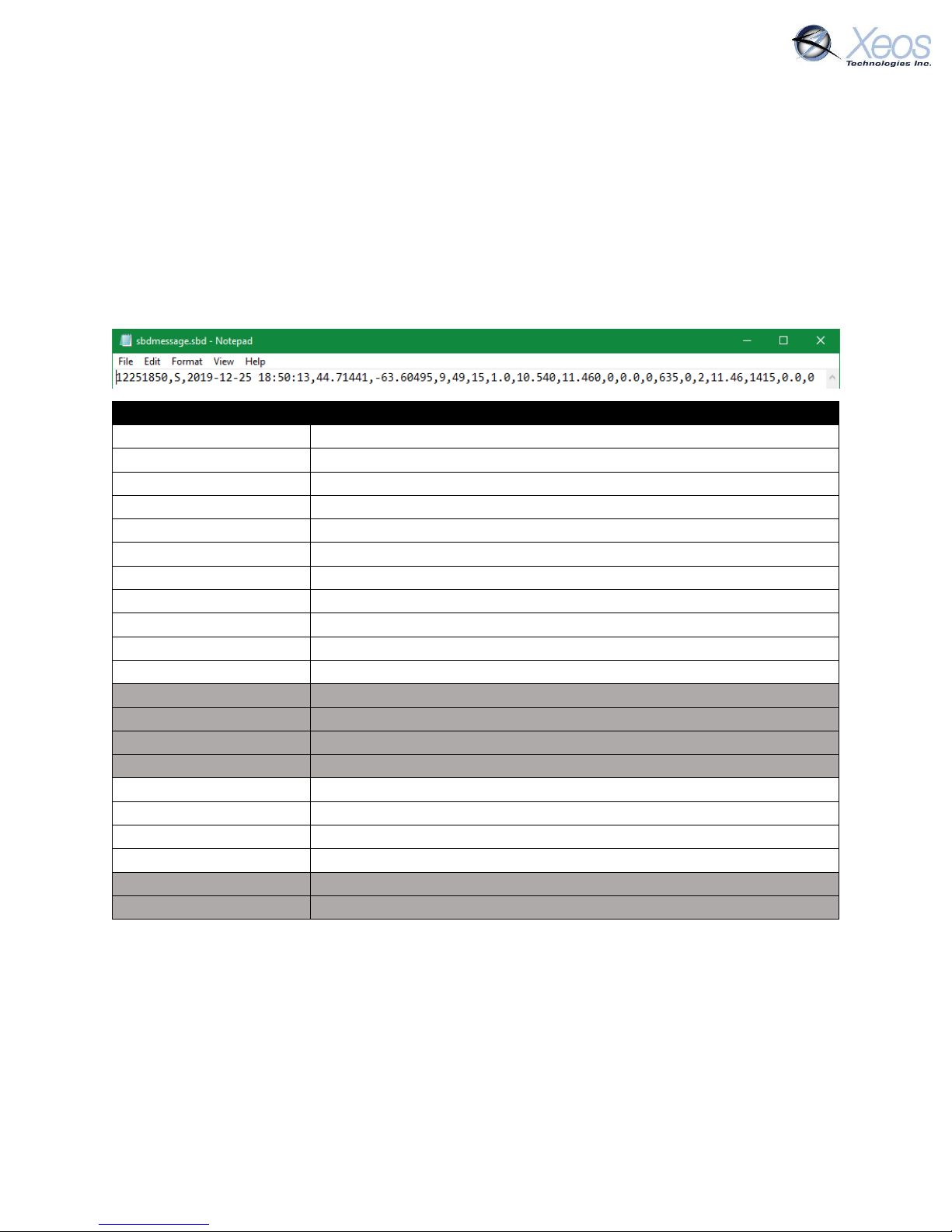
Appendix C: GPS Text Long
GPS Text Long can be used for a more detailed summary of GPS information. This form is only
presented in ASCII format and due to its length is a larger file, at around 110 bytes depending on
the information sent.
Like GPS Text Short, only the most recent GPS position is sent, therefore this message format
cannot be stacked.
Greyed out fields are not used in the OSKER.
GPS Text Long Readout
12251850
Date and Time, MMDDHHMM
S
Status Type message
2019-12-25 18:50:13
Date and time, adds year and second of fix
44.71441
Latitude
-63.60495
Longitude
9
Number of satellites seen
49
Maximum SNR of fix
15
Time to fix
1.0
HDOP (Horizontal Dilution of Precision)
10.540
Loaded Voltage
11.460
Unloaded Voltage
0
Temperature
0.0
Speed
0
Heading
635
GPS Horizontal Error
0
Watch Circle Set 1 (Yes) 0 (No)
2
RSSI (Iridium signal strength)
11.46
Battery Voltage
1415
On-seconds, seconds since power-up/last reset
0.0
Degrees Celcius
0
Movement counter
Page 28

OSKER User Manual Version 3.0 28
Warranty, Support and Limited Liability
Xeos Technologies Inc. warranties the OSKER Beacon to be free of defects in material or
manufacturing for a period of one year following delivery. Liability is limited to repair or
replacement of the defective part and will be done free of charge.
LIMITED WARRANTY: Xeos Technologies Inc. warrants that the product will perform substantially
in accordance with the accompanying written materials for a period of one year from the date of
receipt.
CUSTOMER REMEDIES: Xeos Technologies Inc. entire liability and your exclusive remedy shall be
at Xeos Technologies Inc. option, either (a) return of the price paid or (b) repair or replacement
of the product that does not meet Xeos Technologies Inc. Limited Warranty and that is returned
to Xeos Technologies Inc. with a copy of your receipt. This Limited Warranty is void if failure of
the product has resulted from accident, abuse, or misapplication. Any replacement product will
be warranted for the remainder of the original warranty period or ninety (90) days, whichever is
longer.
NO OTHER WARRANTIES: Xeos Technologies Inc. disclaims all other warranties, either express or
implied, including but not limited to implied warranties of merchantability and fitness for a
particular purpose, with respect to the product or the accompanying written materials. This
limited warranty gives you specific legal rights. You may have others, which vary from state to
state.
NO LIABILITY FOR CONSEQUENTIAL DAMAGES: In no event shall Xeos Technologies Inc. or its
suppliers be liable for any damages whatsoever (including, without limitation, damages for loss
of equipment, for loss of business profits, business interruption, loss of business information, or
other pecuniary loss) arising out of the use of or inability to use this Xeos Technologies Inc.
product, even if Xeos Technologies Inc. has been advised of the possibility of such damages.
 Loading...